Metal Expansion Joint and Flexible Metal Hose
|
|
|
- Ferdinand Stewart
- 6 years ago
- Views:
Transcription


1 KURO Metal Expansion Joint and Flexible Metal Hose l

2 Table of ontents Introduction to Kurbo 1 Metal Expansion Joints Kurbo ellows Type Metal Expansion Joint Typical omposition of Kurbo Metal Expansion Joint ccessories and Options Typical pplication of Expansion Joint in Piping System nchor, Guide and Support Installation and Handling Guide Types of Kurbo Metal Expansion Joints and pplication Single Expansion Joint Universal Expansion Joint Hinged Expansion Joint Gimbal Expansion Joint Externally Pressurized Expansion Joint Pressure alanced Expansion Joint Rectangular Expansion Joint Diesel Expansion Joint Heat Exchanger Expansion Joint Design Data for Standard Expansion Joint Flexible Metal Hose, Flexible Pump onnector Typical onstruction of Flexible Metal Hose Specification of Flexible Tube raided Pump onnector, Flexible Joint ellows Type Pump onnector Flexible Metal Hose onnection Motion of flexible metal hose Installation and Handling Precautions Reference Data ellows Material Selection Guide orrosion Resistance Guide Unit onversion Kurbo Metal Expansion Joint Specification Sheet omplete line of Kurbo Expansion Joint


3 INTRODUTION TO KURO Reborn ompany of Kurbo In 1996, Kurbo ompany Limited was established to design, manufacture and supply rubber expansion joints for a broad range of Industries and now it has been known as leading manufacturer in Korea and sia. Substantial exports have been delivered to over 20 countries. Since 2010, not a few our customers who have purchased our rubber expansion joints for over 10 years and have been very familiar with our service, quality and reliability have asked us to supply metal expansion joints and fabric expansion joints as well, in which we are encouraged to start manufacturing metal and fabric expansion joints and keep sailing around the world. Kurbo s skilled welder using modern TIG welding for bellows and weld end atttachment Manufacturing apability Now we design and manufacture a full range of expansion joints, including single and double unrestrained joints, tied single and double expansion joints, tied universal expansion joints, hinged expansion joints, gimbal expansion joints, pressure balanced expansion joints, externally pressurized expansion joints, heat exchanger expansion joints and rectangular type expansion joints. Mechanical roll forming of bellows ll these assemblies are available with flanged ends, weld ends, internal liners and covers. We have automatic longitudinal welder to weld the pipe/tube and also have hydraulic and mechanical roll forming machines to manufacture bellows which is formed from a thin walled stainless steel tube. With these machines, we manufacture wide variety of expansion joints and their assemblies from DN50 to DN5000. Longitudinal seam welding after rolling tube 1 KURO


4 Design and Engineering apability Our engineers main activity is to design metal expansion joints that can meet or exceed the specific requirements demanded by piping and ducting industry. We design all expansion joints in compliance with EJM latest edition. In addition to the EJM Standard, Kurbo s design also complies with SME Section VIII, SME Section IX, SME 31.1 and SME Kurbo s commitment to develop is reinforced through the use of 3D modeling computer design system technology and finite element analysis, which enables Kurbo to pinpoint potential critical areas and provide timely sound engineered solutions. Quality ssurance and Testing apability With full range of manufacturing, engineering and testing capabilities, Kurbo can provide full quality assurance that its products meet customers needs. ll aspects of manufacture are quality-assured with the plant being accredited to ISO 9001: Various types of testing to ensure quality of products in each stage are performed: These testing includes non-destructive test such as dye penetrant, magnetic particle, ultrasonic, radiography and other performance testing of finished products includes hydro testing, vacuum testing, spring rate testing. Kurbo s bellows design software developed to cater to the design and analysis of the expandable metal bellows Verifying bellows design through movement/spring rate testing Kurbo s 600mm diameter single expansion joint being hydrotested before painting and packaging 2 KURO

5 KURO ELLOWS TYPE METL EXPNSION JOINT Kurbo metallic expansion joints are device containing one or more bellows. They are installed in pipe work and duct systems to prevent damage caused by thermal growth, vibration, pressure thrust and other mechanical forces. Kurbo metallic expansion joints are available in many different designs, shapes and materials in order to absorb axial, lateral, angular movement and concurrent movements. Provided that they are corrected chosen and installed in a professional manner, Kurbo metallic expansion joints are: ellows Movements xial Movements The dimensional shortening or lengthening of an expansion joint along its longitudinal axis Lateral Movement The relative displacement of the two ends of expansion joint perpendicular to its longitudinal axis. Referred to as lateral offset, lateral deflection, parallel misalignment, transverse movement. xial Lateral ngular ngular Movement The displacement of longitudinal axis of expansion joint from its initial straight line position into a circular arc. Referred to as angular rotation, rotational movement Torsional Movement The twisting of one end of the expansion joint with respect to the other end about its longitudinal axis. Kurbo discourages any torsional rotation of metal bellows expansion joints. Torsion destabilizes an expansion joint reducing its ability to contain pressure and absorb movement Rated Movement The maximum amount of movement (axial compression, axial extension, lateral deflection, angular rotation, or any combination thereof) which an expansion joint is capable of absorbing 3 KURO
6 ellows Profile Kurbo manufactures single-wall, multi-wall, heavy-wall metal bellows in many materials and thickness. Single-wall bellows Multi-wall bellows Principle for operation of a bellows corrugation Heavy-wall bellows Toroidal Shape Materials of ellows The basic constituent element of expansion bellows can be specified, taking into consideration the movement, pressure, temperature, service life and corrosion rate required. Our standard material for the circular expansion bellows is austenitic steel like ISI 304, 316 and 321. In addition, other special Nickel based alloy material, like as Inconel, Incoloy, Monel and Hasteloy can be applied on the service of aggressive fluid. asically, austenitic steel is resistant to both high temperature and an aggressive media. It has good mechanical properties as well when it comes to the effect of continuous motion in axial, lateral and angular direction ellows Design The design of bellows is very complex. It involves an evaluation of pressure capability, both internal and external, stress due to deflection, fatigue life, spring forces and instability(squirm). The determination of an acceptable design is further complicated by the numerous variables involved such as diameter, convolution thickness, pitch, height, number of plies of material, method of reinforcement, manufacturing technique, material and heat treatment. ycle Life The cycle life of bellows is proportional to the sum of the meridional pressure stress(ejm stress S4) and total meridional deflection stress(ejm stress S6). The ability of bellows to carry pressure is limited by the S4. This is an important bending stress that is located in the side wall of the convolution running in the longitudinal direction. When a bellows deflects, the motion is absorbed by deformation of side walls of each convolution. The associated stress caused by this motion is the S6. This stress is the primary bending stress influencing fatigue life. It is important to specify realistic cycle life as a design consideration when ordering expansion joint. In many cases, design for application involves compromise of normally conflicting requirements: high pressure usually necessitates thick wall bellows, while low forces and high cyclic fatigue life require thin flexible bellows. 4 KURO
7 TYPIL OMPOSITION OF KURO METL EXPNSION JOINT 1 ellows The flexible element of an expansion joint, consisting of one or more convolutions. This part is the most important one of an expansion joint to absorb axial, lateral and angular movements. The number of convolutions depends on the amount of movement the bellows must accommodate or the force that must be used to accomplish this deflection. ellows is formed from a thin walled stainless steel tube by hydraulic forming or roll forming process. nnealing heat treatment and pickle cleaning are required to remove stress accumulated in bellows during the forming process. There are two types of bellows: Unreinforced bellows and Reinforced bellows 2 End Pipe Mostly made of steel pipes. End pipe is used to connect the bellows with a pipe or flanges. It is of the same quality and dimension as those used for piping. 3 Flange Expansion joint is fitted with cast iron, cast steel, forged steel, plate steel, forged alloy or alloy plate flanges. The choice of flanges is dependent on service conditions. KS and NSI flanges are standard specifications. Special facings and drilling are available to suit unusual service conditions and applications. 5 KURO
8 4 Guide Flange When used with tie rods, it restrain pressure thrust caused by internal pressure in order to prevent damages that may occur in bellows. 5 Internal Sleeve(Liner) It serves to minimize contact between the inner surface of the bellows of expansion joint and the fluid flowing through it and hold friction losses and provide smooth flow. 6 Reinforcing Ring/Equalizing Ring Devices used on expansion joints fitting snugly in the roots of the convolutions. The primary purpose of these devices is to reinforce the bellows against internal pressure. Equalizing rings are made of cast iron, steel, stainless steel or other alloy and are T shaped in cross section. Reinforcing rings are fabricated from tubing or solid round bars of carbon steel, stainless steel or other suitable alloys UNREINFORED ELLOWS 7 Tie Rod Devises, usually rods or assemblies made from rod and pipe whose primary function is to react the full pressure thrust at operating and test conditions, and to allow lateral offset. They can also function as limit stops to prevent over travel of the individual bellows elements of a universal expansion joint, and to stabilize the center spool of a universal expansion joint REINFORED ELLOWS 8 Set olt/shipping ar Shipping bar is installed on an expansion joint to maintain shipping length and give the expansion joint stability during transit and installation. These shipping devices in the form of rod, bar, angle should not be removed until the installation is complete. 6 KURO
9 ESSORIES ND OPTIONS Internal Sleeves/Liners Internal sleeve or liner should be specified for all expansion joint in the following cases: Where friction losses must be held to a minimum and smooth flow is desired Where flow velocities are high and produce resonant vibration. Internal sleeves are recommended when internal flows exceed the following: Typical Flanged Expansion Joint with Liner ir, steam and other gases 1) Up to 6 diameter 4 ft/sec. per inch of diameter 2) Over 6 diameter 25 ft/sec. Water and other liquids 1) Up to 6 diameter 1 2/3 ft/sec. per inch of diameter 2) Over 6 diameter 10 ft/sec. Typical Vanstone Expansion Joint with Liner When turbulent flow is generated upstream of the expansion joint, heavy gauge sleeves are required. Where there is a possibility of erosion, such as in lines carrying catalyst or other abrasive media, heavy gauge sleeves should be used. Where there is a reverse flow, heavy gauge sleeves should be used. When extremely high t emperatures are present, internal sleeves produce an air barrier which will decrease the operating temperature of the bellows. Internal sleeve should not be used where high viscosity fluids are transmitted due to the packing up of fluid. overs/shrouds Kurbo s cover or shroud is used to protect the bellows externally from foreign objects or mechanical damage. It should be specified when the following conditions prevail. Where there is a possibility of accidental damage to the bellows element during shipment, installation or while in service When welding is going to be done in the immediate vicinity of the bellows and there is a possibility of weld splatter or arc strikes hitting the bellows element. When the expansion joint is going to be externally insulated. Note : one end of the cover must be left free to permit movement of the bellows, and the insulation used should be free from any substance which could prove harmful to the bellows material in the event of leaching. Typical Flanged Expansion Joint with over Typical Weld End Expansion Joint with over In the case of Kurbo s externally pressurized expansion joint, the cover is provided as an integral part of the expansion joint and serves as a protection for personnel in the event of a bellows failure. 7 KURO


10 Purge onnections Purge connections are used in conjunction with internal sleeves/liners to: prevent packing or collection of solids in the area between the liner and the bellows. lower skin temperature of the bellows in high temperature applications such as catalytic cracking unit ir Purge Under ellows Tie Rods Tie rods are devises, usually rods or assemblies made from rod and pipe whose primary function is to restrain the full bellows pressure thrust during normal operation while permitting lateral offset. ngular rotation can be accommodated only if two tie rods are used and located 90opposed to the direction of rotation Tie Rod Installed Limit Rods Limit rods are used to restrict the bellows movement range axially, laterally and angularly during normal operation. In the event of anchor failure, the limit rods function as a tie rods and prevent bellows over-extension and over-compression while restraining full pressure loading and dynamic forces generated by anchor failure. This safety device prevent damage to piping, equipment and personnel. Limit Rod Installed ontrol Rods ontrol rods are used to distribute the movement between bellows of a universal expansion joint. These rods are not designed to restrain bellows pressure thrust ontrol Rod Installed 8 KURO

11 TYPIL PPLITION OF EXPNSION JOINTS IN PIPING SYSTEM In selecting proper Kurbo metal expansion joint to satisfy system requirements, it is essential that all the operating parameters be fully considered. The following section is presented as a guide for the piping system designer in evaluating the most significant operating requirements and how to apply them in selecting Kurbo metallic expansion joints. Single expansion joint with flanged end xial Movement pplication Figure through D represents good practice in the use of metallic expansion joint to absorb axial pipeline expansion. Note the relative positions of expansion joints, anchors and guides to achieve proper control of operating conditions. θ θ Figure : Single Expansion Joint pplication between Main nchors Figure : Double Expansion Joint pplication between Intermediate anchor 9 KURO

12 Figure : xial Expansion Joint pplication in a Pipeline with a ranch onnection Figure D : xial Expansion Joint pplication in a Pipeline ontaining a Reducer Lateral Deflection pplication Figure E shows typical arrangement in which the expansion joint is installed in the short piping leg and the principal expansion is absorbed as lateral deflection. The longer piping leg is free of compressive pressure loading and requires only an intermediate anchor and directional guiding Figure E 10 KURO


13 Figure F shows a tied universal expansion joint to absorb lateral deflection in a single plane Z bend. The tie rods absorbing pressure thrust allow the use of intermediate anchors. Where dimensionally feasible, the expansion joint should be designed to fill the entire offset leg so that its expansion is absorbed within the tie rods as axial movement. ny thermal expansion of the offset leg external to the tie rods must be absorbed by bending of the horizontal pipe legs Figure F ngular Deflection pplication Figure G shows a typical arrangement in which Kurbo s three hinged expansion joints are installed in a single plane Z bend. The thermal expansion of offset piping section is absorbed by the action of expansion joints 2 and 3. Note that thrust absorbing Hinges eliminate the need for main anchors and that Kurbo s expansion joint 2 must be capable of absorbing the total of the rotation of expansion joints 1 and 3. Usually center expansion joint contains a greater number of convolutions than those at either end. Just as Kurbo s hinged expansion joints may offer advantages in single plane applications. Kurbo s gimble expansion joints are designed to offer similar advantages in multi plane systems. The advantages of using Kurbo gimble expansion joint systems are similar to those mentioned for systems containing hinged expansion joints. Great flexibility of usage is possible since gimble expansion joints are not restricted to single plane systems. Figure G 11 KURO
14 Typical Forces/Loads in Piping Systems The following formulas are presented so that the load imposed on specific anchor can be calculated. Main anchor loads at straight pipe sections (see Fig. ) FM = FS + FM + FG Main anchor loads at pipe section with reducer (see Fig. D) FM = (FSX- FSY) + (FMX- FMY) + (FGX- FGY) Main anchor loads at pipe bends and elbows (see Fig. ) FM(FLOW) = 2 2pv θ g sin 2 Intermediate anchor loads acting on I (see Fig. ) Notation FM = Force acting on main anchor (kg) FI = Force acting on intermediate anchor (kg) FS = Static thrust due to internal pressure (kg) FM = Force due to expansion joint deflection (kg) FG = Force due to friction in pipe support and guide (kg) = Expansion joint effective area (cm²) ρ = Density of fluid (kg/cm³) v = Velocity of fluid (cm/sec) g = cceleration due to gravity (980 cm/sec²) θ = ngle of pipe bend (degree) M = Main nchor I = Intermediate nchor FI = FM + FG n intermediate anchor is designed to absorb forces due to expansion joint deflection and friction only. It is generally considered as good practice to design the intermediate anchor to resist the forces exerted by large pipe section For lateral and rotational deflection requirements, it is necessary to consider lateral force and bending moments imposed on connection pipe and or equipment (See Figure E, F and G) 12 KURO
15 NHOR, GUIDE ND SUPPORT nchors Pipe anchor divides a pipe line into individual expanding sections that can be considered more easily. The force generated by expansion joint must be absorbed by anchors adequate to take the anticipated loads. The various types of anchor are as follows: Main nchors Main anchors are designed to absorb the full range of loadings and to prevent movement of the pipeline in any direction. Main anchors must be installed at any of the following locations: at a change in direction of flow between two expansion joints of different sizes installed in the same straight run at a entrance of side branch containing unrestrained expansion joint into the main line where shut-off valve or pressure relief valve is installed in a pipe run between two expansion joints at a blind end of a pipe Intermediate nchors Intermediate anchors must be designed to withstand forces and moments imposed upon them which include: force to deflect expansion joint the full rated movements frictional forces due to pipe guides, directional anchors and supports lthough intermediate anchors are not intended to absorb pressure thrust, they must absorb all other forces generated in the system. This force is absorbed by other anchors or by other devices such as tie rods, hinge, gimbal etc. The intermediate anchor is normally an anchor between a double expansion joint where the pressure thrust forces are balanced. Main nchor Intermediate nchor Pipe Guides orrect alignment of the adjoining pipe is of vital importance in the proper functioning of Kurbo s expansion joint system. lthough Kurbo expansion joints are designed and built for long and satisfactory life, maximum service will be obtained only when the pipeline has the recommended number of guides and is anchored and supported in accordance with good engineering practice. Pipe guides are necessary to insure proper application of movement to Kurbo's expansion joint and to prevent buckling of the line. uckling may be caused by a combination of two things: a) flexibility of Kurbo's expansion joint b) internal pressure loading on the pipe Pipe Guide Pipe alignment guides are primarily designed for applications involving only axial extension and compression and have a sleeve or other framework rigidly mounted to positively restrict pipeline movement to compression and extension only. Planar Guide Planar guides are used to restrict movement in one plane and permit movement in another plane. Such restraint is a criterion for stability of most single and universal tied joints when subject to internal pressure. 13 KURO
16 Guide Designs Proper design of both pipe alignment guides and planar pipe guides should allow sufficient clearance between the fixed and moving parts of the alignment guide to insure proper guiding without introducing excessive frictional forces. The first two alignment guides immediately adjacent to each side of Kurbo's expansion joint should be circumferential to the pipe. Planar pipe guides must be designed with additional clearance in one direction to permit the intended lateral deflection and/or bending of the pipe to take place. s in the case of pipe anchors, alignment guides can be subjected to lateral forces as high as 15% of the total axial force, and the system designer must assure himself that the guide, guide attachment and the structure to which it is attached are all designed to conservative stress levels. The design of the total guiding system must assure that no relative shifting of alignment guides and Kurbo expansion joint will occur from ground settlement or other environmental conditions. Kurbo expansion joints that do not include internal guides require an alignment guide to be located 4 pipe diameters from the face of the expansion joint, and second guide 14 diameters from the first guide. typical application for pipe guiding is shown in Figure H on the next page. The remaining guides should be positioned according to pressure and pipe diameter as shown in the Kurbo Guide Spacing Graph on page 15. Maximum intermediate guide spacing for any pipe material or thickness may be calculated using the following formula: L=0.131 EI P+F ex Where L= maximum intermediate guide spacing 2 E = modulus of elasticity of pipe material (kg/mm ) 4 I = moment of inertia of pipe (mm ) 2 P = design pressure (kg/mm ) 2 = bellows effective area (mm ) F = bellows spring rate per convolution (kg/mm/conv.) ex = axial stroke of bellows per convolution (mm/conv.) Notes: 1 When bellows is compressed in operation, use (+) Fex; when extended, use (-) Fex 2 Dead weight of the pipe should also be considered for guide spacing Pipe lignment Guides Pipe Support pipe support permits free movement of the piping and supports only the weight of pipe and fluid. Pipe rings, U-bolts, spring hangers and rollers are examples of pipe supports. However these devices cannot control direction of pipeline movement as does a pipe alignment guide or a planar guide. 14 KURO


17 Recommended Maximum Intermediate Guide Spacing Intermediate Guide Spacing (L)-meter Pressure-bar Figure H : Typical pplication of pipe Guiding 15 KURO
18 16 KURO PIPE THERML EXPNSION TLE Temperature Thermal expansion from 21 to the noted temperature (mm / meter) arbon Steel arbon-moly 3r-Mo lloy Steel 5 r-mo to 9 r-mo ustenitic Stainless Steel 18 r-8 Ni Ferritic Stainless Steel 12 to 27 r Monel 400 opper F

19 INSTLLTION ND HNDLING GUIDE General Proper storage, handling and installation in approved manner are very critical factors so that Kurbo expansion joints can fulfill their function perfectly. Maximum service life can only be obtained by paying attention during handling, storage and installation. If properly installed, expansion joints will need almost no maintenance. Proper installation of your expansion joints is key to increasing the service life and maintaining reliability. This guide is a guideline for general applications. For detailed information, please contact Kurbo directly and inquire about your specific installation Storage, Transportation and Handling Expansion joints should be stored in a dry and clean area. Keep them away from moisture, oil, sand and chemicals. s bellows are made of thin wall plate, they are extremely susceptible to damage. Dents, scratches, arc strikes, weld spatter, and other damage can cause the joint to fail. Our expansion joints are packaged on skids or crated for transportation. The bellows element of the expansion joint is easily damaged and cannot usually be repaired. Do not remove the units from packaging until you are ready to install. Unpack the units carefully. Immediately after unpacking, inspection of the expansion joints has to be done by the customer. ny damage, introduced after this point, will cause the guarantee to void. Installation Kurbo expansion joints being packaged for safe shipment Expansion joints should be installed in the exact position of the pipeline for which they were designed. If not, the cycle life of the expansion joint will reduce considerably and it could even lead to damage of the installation. ll anchors, guides, and supports must be installed according to engineering drawings and specifications. The expansion joint will not be subjected to any torsion. The installation gap is in accordance with the design specifications. Use only designated lifting lugs. Do not lift the expansion joint by the shipping bars. Lift at the lift points provided. If the lift point clevis pins are not apparent, use correct industry practice to lift and position the joint safely. Please be aware bellows can be damaged easily with chains and improper procedures. Make sure that mating flanges are correctly aligned. Do not try to compensate for flange or pipe misalignment by putting any torsional, compressive, extensive, or offset loads on the expansion joint. It is good practice to leave one flange unwelded until the expansion joint has been bolted in position. When bolting the joint, care should be taken not to damage the outside diameter of the end convolutions which may be very close to the flange. Tighten the bolts of the flanges in a crosswise sequence Movement limiting devices such as tie rods, hinges and gimbal can never be removed 17 KURO


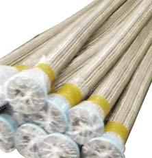
20 s the movement of expansion joint with hinges or gimbals under specific design are limited to certain directions, hinge pins should be in a correct plane to ensure that the expansion joint move and function as intended. The orientation of the hinges is of the utmost importance. Install the hinge pins normal to direction of movement. When internal liners are used, flow direction should be marked. The open end of liner should be towards the downstream side. Flow arrows are shown on the exterior of the unit. Occasionally, the liner may be marked with the flow direction as shown on the right.. Some expansion joints are fitted with permanent covers. If removal of the covers is necessary, they will have to be refitted as quickly as possible. Protect the bellows element from weld spatter and arc strikes. over the bellows with suitable high temperature cloth or insulation. Seal off the open end of liner using duct tape or other suitable material. fter welding inside the unit, remove all pieces of weld rod and spatter which could penetrate the bellows during operation Remove any foreign materials that may have become lodged between convolutions. Remove shipping bars after installation, but prior to system start up/hydro testing. ll shipping bars will be marked with yellow paint with removal information on them. Normally removal information indicates Remove after installation but prior to system start up/hydro testing The expansion joint should not be used for field alignment. ny field alteration to the expansion joint will void the warranty. If an expansion joint has been designed for field alignment it will be stipulated on the drawing. Periodic hecks Visually check the movements absorbed by the expansion joint during working conditions. heck for leaks, mechanical damage, corrosion, unexpected vibrations, etc. ontrol whether any dirt, debris or particles are accumulating between the convolutions of the expansion joints. This could lead to movement restriction and might decrease the life span of the expansion joint Note ll installation procedures should conform to EJM Safety Recommendation in Section. 18 KURO

21 TYPES OF KURO METL EXPNSION JOINT ND PPLITION Single Expansion Joint Single expansion joint is the simplest form manufactured from single and multi-ply elements. It consists of bellows element with end connections. It is used for axial movement only in pipe configurations. However, it can also absorb small amounts of other two types of basic movements-lateral and angular. This type of expansion joint provides most economical solution in an installation where proper anchoring and guiding is feasible. Features bsorbs all three types of movement Deflects in any direction No change in direction of flow Minimum installation space and easy to install The least expensive type of expansion joint Strong anchors require to control pressure thrust Untied Single Expansion Joint This type of expansion joint, without any restraints or guides, cannot resist deflections other than those due to spring rate of the bellow elements. The piping should be adequately guided and anchored to avoid unexpected movements and proper functioning of the expansion joint. Typical application of a single expansion joint is to absorb axial movements of straight pipe between main anchors. When axial movement of the piping run exceeds the capability of single expansion joint, double expansion joint with intermediate anchor welded to a center spool may be used. SEJ Tied Single Expansion Joint It has all the characteristics of the untied expansion joint with addition of tie rods to restrain the pressure thrust and to restrict the movement of expansion joint TSEJ 19 KURO

22 Universal Expansion Joint Universal expansion joint consists of two bellows elements joined together by a piece of pipe(center spool) and fitted with either pipe ends or flanges. This type of expansion joint is usually furnished with control rods to distribute the movement between two bellows of the expansion joint and stabilize the center spool. When large amount of lateral deflection is required, universal expansion joint is used. For a given bellows element, the amount of lateral deflection capability can be increased or decreased by simply changing the length of the center spool. In addition to this, these assembly can also compensate other two types of movements: axial and angular, but is limited to low pressure applications because of center spool instability. This type of expansion joint also will result in lower forces on the anchors. Only light fixed points are required to absorb lateral movement and friction forces. Untied Universal Expansion Joint Untied universal expansion joints can absorb large amount of lateral deflections in addition to axial and angular movements. Usually these type of expansion joints are provided with control rods to distribute the movement equally between the two bellows. ontrol rods are not designed to withstand pressure thrust. Kurbo s engineers are checking bellows quality of tied universal expansion joint Features bsorbs large amounts of lateral deflection Simple and robust construction Eliminates pressure thrust load Low maintenance Tied Universal Expansion Joint It is same as untied universal expansion joints, but with addition of tie rods. These tie rods are designed to withstand the pressure thrust and so the external movement of the expansion joint is constrained even if the pressure thrust is increased. ngular movement can be accommodated only if two tie rods are provided 180 degree apart. To restrict this angular movement, four tie rods are provided at interval of 90 degrees, around the circumference of the expansion joint. lthough an axial expansion joint itself is less expensive than a tied universal expansion joint, when the anchoring and guiding costs are taken into consideration, there is no contest. The tied universal expansion joint has a much lower installed cost. UEJ TUEJ 20 KURO

23 Hinged Expansion Joint Hinged expansion joint is designed to permit angular rotation in one plane only by the use of a pair of pins through hinge plates attached to the expansion joint ends. The hinge and hinge pin is designed to restrain the pressure thrust loads and other external loads such as dead weight and wind. Slotted hinges assembly can also be provided to allow some amount of axial deflection. These slotted hinge types will not resist pressure thrust forces, and anchoring must be provided. If the full axial restraint of the hinged type is desired, the piping designer should understand that there is no allowance in the expansion joint for any axial travel, including none for any installation misalignment Features Permits angular rotation in one plane. Eliminates pressure thrust forces No main anchors required Transmits loads, so low forces on the pipe anchors Prevents torsion or twisting of the expansion joint. an also absorb axial deflection, if designed. Internal flow liners for eliminating velocity problem nchors only required to absorb spring forces Hinged expansion joints can be fitted with either pipe ends or flanges and are used in sets of two or three to function properly Two Hinge System Three Hinged Expansion Joint Double Hinged Expansion Joint Double hinged expansion joint consist of a two bellows with two pairs of hinges. This type of expansion joint is used to accommodate large amount of lateral deflection in one plane. y providing a special arrangement of hinge box, the universal hinge expansion joint can also accommodate angular movement and lateral deflection in more than one plane. 21 KURO

24 Gimble Expansion Joint Gimbal expansion joint is designed to permit angular rotation in any plane by the use of two pairs of hinges affixed to common floating gimbal ring. This expansion joint can consist of a single bellow, where there is no lateral deflection, or two bellows connected by a common connector/pipe spool where it can permit a lateral deflection also. The gimbal ring, hinges and pins must be designed to restrain the pressure thrust loads and other external loads such as dead weight and wind Features Permits angular movement in any plane Eliminates pressure thrust forces No main anchors required Transmits loads, so low forces on the pipe anchors Prevents torsion or twisting of the expansion joint. Internal flow liners for eliminating velocity problem nchors only required to absorb spring forces Typical gimbal systems consist of two gimbal expansion joints or two gimbal and one hinged expansion joint s hinged expansion joints may offer great advantages in one plane applications, gimbal type offer similar advantages in multi-plane systems. The ability of gimbal expansion joint to absorb angular rotation in any plane is most frequently applied by utilizing two such units to absorb lateral deflection. In a two gimbal system, the thermal growth of vertical pipe leg must be absorbed by bending of long horizontal piping and gimbal units absorb the thermal expansion from the two horizontal piping legs. Typical application is shown below. Where it is impossible or undesirable for the piping to absorb the growth of the offset leg, a system consisting of two gimbal and one hinged expansion joints are to be used as shown below. The gimbal expansion joints function in unison to absorb the combined movements of the upper and lower legs while the hinged expansion joint and the upper gimbal expansion joint act in combination to absorb deflection of the offset leg. Since the expansion of offset leg takes place in one plane only, the use of simpler hinged expansion joint is justified. 22 KURO

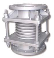
25 Externally Pressurized Expansion Joint Externally pressurized expansion joints are alternative for standard axial expansion joints. This type of expansion joint is designed so that the pressure is external to the bellows for maximum stability. This unique design makes it possible to allow large amount of axial movements while containing high pressure and high temperature. Kurbo offers 100mm, 150mm and 200mm axial travels with single expansion joint. For larger movement up to 400mm axial travel, dual configuration can be designed.. pplications Replace costly equalizing expansion joint system Replace space confining pipe loop Replace maintenance required slip joints Ideal for long pipe run steam lining that require high pressure/temperature containment with lots of axial movement Features bsorb large amount of axial movements Pressure thrust will be transmitted onto the pipeline ellows element is externally pressurized Totally enclosed for maximum safety orrect anchoring and guiding must be used Drains naturally due to gravity vailable with optional drain port Leak-proof and no packing Pressure is external to bellows for safety dvantages Safety The outer cover contains the full line pressure of the system, thus in the event of bellows failure, the media could not escape radially outward and harm personnel in the area. No dditional Liner Smooth flow eliminates the need for liners Self Draining Kurbo standard type of externally pressurized expansion joints come with drain port. The sediment or residue collects at the bottom of the casing for easy venting, thus reducing the corrosion problems. Maintenance Free/ Improvement over Slip Type This type of expansion joint does not require maintenance or need lubrication or repacking, therefore making it ideal in areas where accessibility is limited. This is a distinct improvement over the slip type. When a pipeline expands, expansion joint compresses, but it stretches the bellows. ellows remains stable due to external pressure 23 KURO

26 Pressure alanced Expansion Joint One of the main problems when installing high pressure bellows particularly with large diameters is that these units must be properly anchored and guided. There are certain installations where this is not practical, nor economical. These types of expansion joints are used in application where main anchoring is not practical and in piping system where pressure loads are critical, and where complex axial and lateral movements are involved with limited space and also seen in piping connecting two load sensitive equipments Features bsorb axial and small amounts of lateral movement Eliminate pressure thrust Reduce piping costs Eliminate main anchors No volume change Stable at high pressures Simple to manufacture Solution to Many Excessive Loading Problems on Piping and Equipment Elbow Pressure alanced Expansion Joint Elbow pressure balanced expansion joint is designed to restrain and balance the pressure thrust so that main anchor of the pipe or adjacent equipment is not required. This type of expansion joint consists of one or two flow bellows and one balancing bellows. The pressure is balanced by allowing the pressure to pass through a hole in the back of the bend into a sealed bellows having the same effective area. When large amounts of lateral movement are required, we would prefer the use of double pressure balanced joint. In this design two bellows are used in the flow line end of the expansion joint and a single bellows in the balancing end. The balancing bellows is subjected to axial deflection only, while the flow bellows absorbs lateral and/or axial deflections. These bellows can be also used at the bends of the piping or change in direction of piping, where adequate support or main anchors is not possible. Elbow Pressure alanced Expansion Joint In-Line Pressure alanced Expansion Joint Inline pressure balanced expansion joint is designed to absorb axial, lateral and angular deflection while restraining the pressure thrust by use of tie rods, without a change of direction in a piping run. This type of expansion joint consists of two flow bellows and one balancing bellow. The effective area of the balancing bellow is twice that of the flow bellow. When flow bellows are compressed by thermal expansion, the balancing bellows extend an equal amount due to tie rod arrangement. s no volume change occurs, the pressure forces remain in balance. So the forces exerted on the pipe anchors or the adjacent equipments is eliminated. In-Line Pressure alanced Expansion Joint 24 KURO


 No.")
27 Rectangular Expansion Joints Rectangular type expansion joints are mostly used in low pressure ducting systems including gas turbine exhaust systems, turbine/condenser connections, boiler breaching, flue gas ducts, regenerators, precipitators. Kurbo also designs and manufactures a wide range of rectangular type metal expansion joints to compensate for axial, lateral and angular movements and any combination of these. Rectangular and square type expansion joints are designed to suit each customer s individual requirements. Please contact one of our sales engineers for any assistance. These rectangular type joints are available with a large range of options including liners, covers, tie rods, hinges, internal packing, purge and drain points. Rectangular double expansion joint with round corners Design Standard ellows Type Max. Working Pressure (bar) No. of onvolution xial Movement Overall Length L50 L65 L75 L100 Spring Rate (kg/mm) Miter & Round orner amera orner Rectangular joint with single miter V profile Kurbo s inspector performing hydrostatic test 25 KURO
28 orner onfiguration and onvolution Profile Rectangular type expansion joints are available in four different corner configurations and two convolution profiles. The application and operating conditions will dictate the correct choice of convolution shape and corner configuration. Typical convolution geometry and corner construction details are shown below. orner onfiguration Single Miter orner This is the most common and economical type used to compensate for thermal expansion, and can readily be bolted or welded into the connecting duct work. These are preferred in low cycle and vibrationfree applications. Single Miter orner Double Miter orner This type is slightly more expensive to manufacture than the single miter design. However, they do provide a greater cycle life under the same set of operating conditions. Rounded orner This type is used in applications where vibration and cycle life are important factors. Rounded corners are the most costly to manufacture though, it has advantage of lowering corner stress. amera orner This type is used mainly on lowpressure applications. They have good cycle life characteristics and are less costly than the double miter corner design. amera corners have disadvantage of reduction in movement because convolutions are overlapped at the corner. Kurbo does not recommend this type of joint. Double Miter orner Rounded orner amera orner onvolution Profile There are two types of convolution: V-shaped and U-shaped. "V profile is used for low pressure applications and "U" profile is preferred for higher pressure applications up to 2bars. The "V" convolution profile will be supplied with single miter corners, unless otherwise specified. Round corner bellows will always be constructed using the "U" convolution profile. Setback U Profile V Profile 26 KURO


29 Other Types of Expansion Joint Diesel (Engine) Expansion Joint This type of exhaust expansion joints are installed very close to the engines and are subjected to severe conditions of temperature, movements and vibrations. The design of this type of expansion joints requires a thorough expertise due to the challenging demands on them like: High temperatures in manifold area, more than 400 deg bsorption of high thermal expansion and severe vibrations, thereby resulting in stress relief Temperature peaks according to engine output. ompact overall dimensions due to space restrictions Easy and quick dismantling and assembly to avoid engine down-time These expansion joints can be supplied with the required end connections matching to adjacent pipe. lso one flange can be supplied in rotary condition to properly align the flange holes with the mating flange at site of installation Heat Exchanger Expansion Joint The expansion joints used as an integral part of heat exchanger are designed to provide flexibility for thermal expansion and also to function as a pressure containing element. The bellows consist of formed flexible elements with multiple or single convolutions and will be of the unreinforced or reinforced type depending upon operating pressure. ellows are fabricated of austenitic stainless steel, Hastelloy, Inconel etc. Design of this type of expansion joint complies with the standards of both SME Section and EJM latest edition. 27 KURO
30 STNDRD EXPNSION JOINT DESIGN DT Single ellows Unit Double ellows Unit Externally Pressurized Unit This data sheets list only Kurbo standard metal expansion joints. For a design not included in this catalogue, please contact Kurbo at kurbo@kurbo.co.kr or at The specifications in this data sheets are subject to change for product improvement 28 KURO


 OL WW WT (kg) OL FF WT (kg) 50 2 65 2.")
31 SINGLE ELLOWS UNIT (SEJ, TSEJ, HEJ, GEJ) Types of Expansion Joints SEJ TSEJ HEJ GEJ End onnections Weld End Flange Van Stone Flange Flange / Weld End Van Stone / Weld End Van Stone / Flange WW FF VV FW VW VF Pressure: 75 PSI / 5 ar Nominal Size mm inch Non-oncurrent Movement Spring Rate Overall Length and Weight xial Lateral ngular (deg.) xial (kg/mm) Lateral (kg/mm) ngular (kg m/deg.) OL WW WT (kg) OL FF WT (kg) KURO
32 Nominal Size mm inch Non-oncurrent Movement Spring Rate Overall Length and Weight xial Lateral ngular (deg.) xial (kg/mm) Lateral (kg/mm) ngular (kg m/deg.) OL WW WT (kg) OL FF WT (kg) Part Numbering System Example : 150 ND/DN SEJ TYPE WW END 5 PRESS L LINER Notes 1. Rated cycle life is 5000 cycles for any one movement tabulated per EJM. 2. To obtain greater movement or cycle life, contact Kurbo 3. Maximum axial extension movement is half of tabulated axial value 4. Standard materials for flange, pipe and attachment are carbon steel 5. Standard bellows materials in SS 304,316 and For higher pressure, temperature, movement and cycle ratings, contact Kurbo. 7. orrect anchoring and guiding must be used. 8. Multi ply, Toroidal bellow are also available. 30 KURO
 xial (kg/mm) Lateral (kg/mm) ngular (kg m/deg.")
33 SINGLE ELLOWS UNIT (SEJ, TSEJ, HEJ, GEJ) Types of Expansion Joints SEJ TSEJ HEJ GEJ End onnections Weld End Flange Van Stone Flange Flange / Weld End Van Stone / Weld End Van Stone / Flange WW FF VV FW VW VF Pressure: 150 PSI / 10 ar Nominal Size mm inch Non-oncurrent Movement Spring Rate Overall Length and Weight xial Lateral ngular (deg.) xial (kg/mm) Lateral (kg/mm) ngular (kg m/deg.) OL WW FF ftq WT (kg) OL WT (kg) KURO
34 Nominal Size mm inch Non-oncurrent Movement Spring Rate Overall Length and Weight xial Lateral ngular (deg.) xial (kg/mm) Lateral (kg/mm) ngular (kg m/deg.) OL WW FF ftq WT (kg) OL WT (kg) Part Numbering System Example : 150 ND/DN SEJ TYPE WW END 10 PRESS L LINER Notes 1. Rated cycle life is 5000 cycles for any one movement tabulated per EJM. 2. To obtain greater movement or cycle life, contact Kurbo 3. Maximum axial extension movement is half of tabulated axial value 4. Standard materials for flange, pipe and attachment are carbon steel 5. Standard bellows materials in SS 304,316 and For higher pressure, temperature, movement and cycle ratings, contact Kurbo. 7. orrect anchoring and guiding must be used. 8. Multi ply, Toroidal bellow are also available. 32 KURO
35 SINGLE ELLOWS UNIT (SEJ, TSEJ, HEJ, GEJ) Types of Expansion Joints SEJ TSEJ HEJ GEJ End onnections Weld End Flange Van Stone Flange Flange / Weld End Van Stone / Weld End Van Stone / Flange WW FF VV FW VW VF Pressure: 300 PSI / 20 ar Nominal Size mm inch Non-oncurrent Movement Spring Rate Overall Length and Weight xial Lateral ngular (deg.) xial (kg/mm) Lateral (kg/mm) ngular (kg m/deg.) OL WW FF ftq WT (kg) OL WT (kg) KURO
 OL WW FF ftq WT (kg) OL WT (kg) 500 20 550 22 600 24 Part Numbering System Example : 150 ND/DN SEJ TYPE WW END 20 PRESS L LINER Notes 1.")
36 Nominal Size mm inch Non-oncurrent Movement Spring Rate Overall Length and Weight xial Lateral ngular (deg.) xial (kg/mm) Lateral (kg/mm) ngular (kg m/deg.) OL WW FF ftq WT (kg) OL WT (kg) Part Numbering System Example : 150 ND/DN SEJ TYPE WW END 20 PRESS L LINER Notes 1. Rated cycle life is 5000 cycles for any one movement tabulated per EJM. 2. To obtain greater movement or cycle life, contact Kurbo 3. Maximum axial extension movement is half of tabulated axial value 4. Standard materials for flange, pipe and attachment are carbon steel 5. Standard bellows materials in SS 304,316 and For higher pressure, temperature, movement and cycle ratings, contact Kurbo. 7. orrect anchoring and guiding must be used. 8. Multi ply, Toroidal bellow are also available. 34 KURO
37 DOULE ELLOWS UNIT (UEJ, TUEJ, DHEJ, DGEJ) Types of Expansion Joints UEJ TUEJ DHEJ DGEJ Pressure: 75 PSI / 5 ar Nominal Size mm inch Movement Spring Rate Overall Length and Weight xial Lateral xial (kg/mm) Lateral (kg/mm) OL WW WT (kg) OL FF WT (kg) Notes 1. Rated cycle life is 5000 cycles for any one movement tabulated per EJM. 2. To obtain greater movement or cycle life, contact Kurbo 3. Maximum axial extension movement is half of tabulated axial value 4. Standard materials for flange, pipe and attachment are carbon steel 5. Standard bellows materials in SS 304,316 and For higher pressure, temperature, movement and cycle ratings, contact Kurbo. 7. orrect anchoring and guiding must be used. 8. Multi ply, Toroidal bellow are also available. 35 KURO
38 DOULE ELLOWS UNIT (UEJ, TUEJ, DHEJ, DGEJ) Types of Expansion Joints UEJ TUEJ DHEJ DGEJ Pressure: 150 PSI / 10 ar ftq Nominal Size mm inch xial Movement Spring Rate Overall Length and Weight Lateral xial (kg/mm) Lateral (kg/mm) WW OL WT (kg) OL FF WT (kg) ftq Notes 1. Rated cycle life is 5000 cycles for any one movement tabulated per EJM. 2. To obtain greater movement or cycle life, contact Kurbo 3. Maximum axial extension movement is half of tabulated axial value 4. Standard materials for flange, pipe and attachment are carbon steel 5. Standard bellows materials in SS 304,316 and For higher pressure, temperature, movement and cycle ratings, contact Kurbo. 7. orrect anchoring and guiding must be used. 8. Multi ply, Toroidal bellow are also available. 36 KURO
 Lateral (kg/mm) OL WW WT (kg) OL FF WT")
39 DOULE ELLOWS UNIT (UEJ, TUEJ, DHEJ, DGEJ) Types of Expansion Joints UEJ TUEJ DHEJ DGEJ Pressure: 300 PSI / 20 ar Nominal Size mm inch Movement Spring Rate Overall Length and Weight xial Lateral xial (kg/mm) Lateral (kg/mm) OL WW WT (kg) OL FF WT (kg) f Part Numbering System Example : 200 ND/DN UEJ TYPE FF END 20 PRESS L LINER Notes 1. Rated cycle life is 5000 cycles for any one movement tabulated per EJM. 2. To obtain greater movement or cycle life, contact Kurbo 3. Maximum axial extension movement is half of tabulated axial value 4. Standard materials for flange, pipe and attachment are carbon steel 5. Standard bellows materials in SS 304,316 and For higher pressure, temperature, movement and cycle ratings, contact Kurbo. 7. orrect anchoring and guiding must be used. 8. Multi ply, Toroidal bellow are also available. 37 KURO
40 38 KURO q SXP DXP mm inch Nominal Size Type xial Movement Length FF & WW Pressure Thrust (kg) EXTERNLLY PRESSURIZED EXPNSION JOINT Pressure: 150 PSI / 10 ar ftq mm inch Nominal Size Type xial Movement Length FF & WW Pressure Thrust (kg) Pressure: 300 PSI / 20 ar
 200 8 200 8 250 10 250 10 Part Numbering System Example : 150-SXP-WW-10-100-D 150 ND SXP TYPE WW END 10 PRESS 100 MOVT D OPTION D: Drain connection P: Purge connection q Notes 1.")
41 Pressure: 150 PSI / 10 ar Pressure: 300 PSI / 20 ar Nominal Size xial Type Movement mm inch Length FF & WW Pressure Thrust (kg) Nominal Size xial Type Movement mm inch Length FF & WW Pressure Thrust (kg) Part Numbering System Example : 150-SXP-WW D 150 ND SXP TYPE WW END 10 PRESS 100 MOVT D OPTION D: Drain connection P: Purge connection q Notes 1. Rated cycle life is 5000 cycles for non-concurrent movement tabulated per EJM. 2. Maximum test pressure is 1.5 times the rated pressure 3. For special component, please specify and contact Kurbo 39 KURO
42 40 KURO


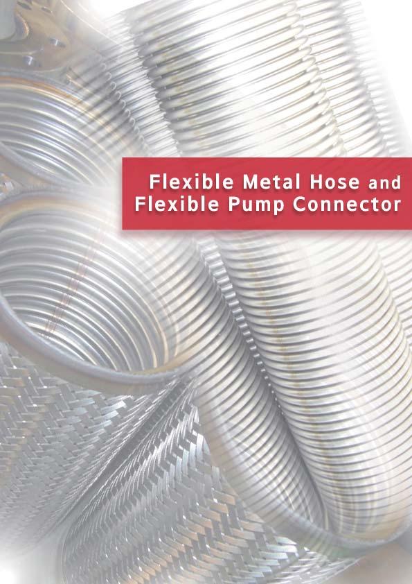
43 FLEXILE METL HOSE Flexible metal hoses are widely used in systems like water, steam, hot oil and gas with their resistance to pressure and excellent flexibility: To absorb heat or pressure-induced expansion of piping system To correct problems of misalignment. To provide flexibility in manual handling operations. To compensate for regular or constant movement. To absorb vibration and noise. Typical onstruction of Flexible Metal Hose Flexible metal hose is generally fabricated of three parts: flexible tube, braid and end fittings such as flanges, unions, nipples, sockets Flexible Tube flexible metal tube, made of stainless steel thin wall pipe, has a good flexibility, high strength, heat resistance and pressure containment. There are two types of flexible tubes-spiral type and nnular type. Spiral type flexible tube is a helically corrugated hose and is usually used in medium and low pressure application. nnular type flexible tube has annular corrugation so that it does not tend to be twisted when subjected to elongation and contraction. onsequently it is suitable for use in high pressure application. End Fitting raid raid flexible wire sheath surrounding a metal hose that prevents the hose from elongation due to internal pressure. raid is composed of a number of wires wrapped helically around the hose while at the same time going under and over each other in a basket weave fashion. End Fitting Extensive range of end fitting is available. End fitting may have male or female threads. In addition to conventional flanges, unions, nipples, special designs or custom connectors are available. The attachment method: welding, soldering, silver brazing or mechanical, is determined by the appropriate type of hose, alloy and temperature. ontact Kurbo for custom fitting information Flexible Tube 41 KURO
 ID OD Thick.")
44 Specification of Flexible Tube Spiral Tube Spirally corrugated tube, fabricated of stainless steel type 304, 316L, 321 and other alloys. Nominal Size DN Inch 8 1/4 10 3/8 15 1/2 20 3/ / / / Dimension end Redius Weight(kg/m) ID OD Thick. Tube raid urst Pressure (bar) Note : urst pressure is based on braided tube nnular Tube nnularly corrugated tube, fabricated of stainless steel type 304, 316L, 321 and other alloys Nominal Size DN Inch / / / Dimension end Redius Weight(kg/m) ID OD Thick. Tube raid urst Pressure (bar) Note : urst pressure is based on braided tube 42 KURO

45 FLEXILE PUMP ONNETOR Kurbo flexible pump connectors are primarily used to absorb noise and vibration transmitted by mechanical equipments like pumps and compressors. The flexible metal pump connectors are of all steel construction, thus they permit high pressure and high temperature service while isolating mechanical vibration and reducing system noise to provide perfect pump vibration isolation. Kurbo flexible metal pump connectors are available in two (2) types: raided pump connector (known as flexible joint) and ellows type pump connector. raided Pump onnector onstruction onstructed of stainless steel hose and braid, carbon steel flat faced plate flanges as a standard. Features bsorbs mechanical equipment vibrations in the connected piping Noise associated with the vibration is eliminated Lowers overall operating costs ompensates for minor misalignment, resulting in less stresses llows operation at elevated temperature. Nominal Size Length Max. Working Pressure(bar) raid DN Inch (L) Single raided Double raided pprox. Weight(kg) / / / an be manufactured in different lengths 43 KURO

46 ellows Type Pump onnector In addition to the benefit and advantage of the braided pump connector, the bellows pump connectors provide the ultimate flexibility combined with low spring rate and internal dampening of vibration which results in pump vibration isolation and high service life without compromising pressure resistance strength. This type offers ideal solution to vibration and motion isolation when space is at a premium onstruction onstructed of multiple layers of stainless steel bellows, carbon steel flat faced flanges. Isolation of the carbon steel flanges from the flow media can be achieved by the use of vanstone flanges. Tie rods are designed to absorb the full pressure thrust load generated by the internal pressure. Features bsorbs thermal growth motion bsorbs mechanical equipment vibrations in the connected piping Eliminates noise associated with the vibration Provides high flexibility and longer service life due to multiply construction of bellows ompensates for minor misalignment, resulting in less stresses llows operation at elevated temperature. Nominal Size Overall Length Maximum Movement pprox. Weight DN Inch KS / JIS 10K 25 1 KS / JIS 20K xial omp. xial Ext. Lateral KS / JIS 10K KS / JIS 20K an be manufactured in different lengths and different flange 2. Movement are non concurrent movements 44 KURO
47 FLEXILE METL HOSE ONNETION WLF-1 WFF-1 Loose Flange / S Fixed Flange / S Stub End / S or SS304 raid and / SS304 Flexible Tube / SS304 Flexible Tube / SS304 raid / SS304 raid / SS304 DN Inch I Flange DN Inch I Flange Flange dimensions Flange dimensions to the standards to the standards such as KS, JIS, NSI, such as KS, JIS, NSI, WW, S, DIN etc. WW, S, DIN etc. WLF-2 WFF-2 Loose Flange / S Fixed Flange / S Stub End / S or SS304 End Pipe / S or SS304 Neck Ring / S or SS304 Neck Ring / S or SS304 raid and / SS304 raid and / SS304 Flexible Tube / SS304 Flexible Tube / SS304 raid / SS304 raid / SS304 DN Inch I Flange DN Inch I Flange Flange dimensions Flange dimensions to the standards to the standards such as KS, JIS, NSI, such as KS, JIS, NSI, WW, S, DIN etc. WW, S, DIN etc. Note: Specifications subject to change without notice 45 KURO
48 WLF-3 WFF-3 Loose Flange / S Fixed Flange / S Stub End / S or SS304 End Pipe / S or SS304 raid and / SS304 raid and / SS304 Flexible Tube / SS304 Flexible Tube / SS304 raid / SS304 raid / SS304 Nominal Size DN Inch I Flange Nominal Size DN Inch I Flange Flange dimensions to the standards such as KS, JIS, NSI, WW, S, DIN etc. Flange dimensions to the standards such as KS, JIS, NSI, WW, S, DIN etc. WNP WSK Nipple / M Socket / S raid and / SS304 raid and / SS304 Flexible Tube / SS304 Flexible Tube / SS304 raid / SS304 raid / SS304 Nominal Size DN Inch T d I H Nominal Size DN Inch T d I H Note: Specifications subject to change without notice 46 KURO
49 WUN WHU Union / M Packing / PTFE or Non-Metal Packing Flexible Tube / SS304 raid / SS304 HU Fitting / S Packing / PTFE or Non-Metal Packing Flexible Tube / SS304 raid / SS304 Nominal Size DN Inch T I H Nominal Size DN Inch T d I H WSN-M WSN-F Nipple / S SN-M Fitting / S raid and / SS304 Flexible Tube / SS304 raid / SS304 Swivel Nut / S SN-F Fitting / S raid and / SS304 Flexible Tube / SS304 raid / SS304 Nominal Size DN Inch Nominal Size T d I H T d I H DN Inch Note : Specifications subject to change without notice 47 KURO


50 WP WQ oupler Nipple / S raid and / SS304 Flexible Tube / SS304 raid / SS304 Quick oupling Nipple / S raid and / SS304 Flexible Tube / SS304 raid / SS304 Nominal Size DN Inch T d I I Nominal Size DN Inch T d I I Note: Specifications subject to change without notice 48 KURO
51 MOTION OF FLEXILE METL HOSE Offset Motion This type of motion occurs when one end of the hose is deflected in a plane perpendicular to its longitudinal axis with the ends remaining parallel. In offset motion application, the offset should never exceed 25 percent of the centerline bend radius R LP L R Y L= 6YR + Y Lp= L - Y Vertical Motion T/2 T/2 Vertical motion occurs when the center line of a hose assembly is bent in a circular arc and moves in a vertical direction. K 2R L=4R+T/2 K=1.43R+T/2 K Support 2R Horizontal Motion Horizontal motion occurs when the center line of a hose assembly is bent in a circular arc and moves in a horizontal direction K1 L=4R+1.57T K1=1.43R+0.785T K2=1.43R+T/2 K1 Support ngular Motion ngular Motion occurs when one end of a hose assembly is deflected in a simple bend with the ends not remaining parallel. R L θ L= θ 180 xial Motion xial motion means dimension variation of a flexible hose along its longitudinal axis. raided hose or helically corrugated hose should not be subjected to axial motion. This mode of motion is restricted to unbraided corrugated hose only and is accommodated by travelling loops Notation: L = Live hose length Lp = Projected live hose length R = end radius from center line Y = Offset motion to one side of center line T = Total travel K = Loop length θ = ngle of end (degrees) 49 KURO
52 INSTLLTION ND HNDLING PREUTIONS Proper installation in an approved manner are very critical factors so that Kurbo flexible metal hose can fulfill its function perfectly. Kurbo flexible metal hose is engineered to provide maximum service life when properly installed. Improper installation, incorrect flexing or careless handling in an application will reduce the effective service life of the hose and cause premature failure of an assembly. The following installation and handling precautions should be observed to achieve optimum performance from your hose assemblies. ORRET WRONG Do Not Torque Do not twist hose when aligning bolt Motion Motion holes in a flange or when making up pipe threads. To minimize possible Motion Motion torque damage to flexible hose, the use of loose flange or union will help. lways install flexible hose so that flexing takes place in one plane only. ORRET WRONG Motion Motion Motion Motion void Over ending ORRET WRONG Do not over bend a flexible hose. Pre-flexing of flexible hose to limber WRONG up should be avoided. Over-bending could cause damage and result in ORRET premature failure void Sharp end s a result of improper installation, WRONG flexible hose can be subjected to recurring sharp bend. void sharp ORRET bends, especially near the end fittings of the hose R Provide Support When installed in a horizontal loop, ORRET WRONG No Support Sagging and sharp bends provide support to prevent hose from sagging/drooping. Support 50 KURO
53 Reference Data ontents ellows Material Selection Guide page 53 orrosion Resistance Guide 54 Unit onversion 57 Metal Expansion Joint Specification Sheet 59
54 ELLOWS MTERIL SELETION GUIDE Material SS 304 General Properties and Manufacturing vailability Standard material for manufacture of bellows. Usually this grade is used in water or steam applications. For operating temperatures to 450 SS 304L ellows can be supplied in this material when required, subject to availability of sheet of the required gauge SS 316 Improved corrosion resistance as compared to the 321, especially with regard to pitting corrosion. Typical uses include high sulphur crude oils, brackish waters, flue gases, food processing and numerous applications in chemical and petrochemical processing. SS 321 dequate corrosion resistance and mechanical properties at ambient and elevated temperatures, 450 to 815. SS 310 This grade is sometimes requested for special purposes. ecause of difficulty in obtaining material suitable for bellows manufacture, we usually offer Incoloy 800 as a superior alternative material where necessary. Incoloy 800 ellows can be supplied in this material when its good corrosion resistance and high temperature properties are required to meet service conditions. Inconel 600 ellows can be manufactured from this material when required. The alloy combines good general corrosion resistance with virtual immunity to chloride stress corrosion and also has good high temperature strength and oxidation resistance. Inconel 625 One of the more recent nickel-chrome molybdenum alloys combining good high temperature properties with good resistance to chloride stress corrosion and a variety of corrosive environments. Monel 400 This nickel-copper alloy finds limited use for bellows manufacture in some specialized applications such as chlorine service. However the manufacture of small diameter bellows would be uneconomic, and we advise that an alternative material should be used where the service conditions permit. Hastelloy 276 nickel-chrome molybdenum alloy having outstanding resistance to a wide variety of severely corrosive chemical process environments including: wet chlorine, hypochlorites, chlorine dioxide solutions, hot contaminated mineral acids and acetic acid, sea water and brine. ellows can be supplied when required, subject to the availability of sheet material. 53 KURO
55 ORROSION RESISTNE GUIDE This "orrosion Resistance Guide" is to be used only as a guide in selecting the most satisfactory material for resistance to various chemical solutions. If in question, contact Kurbo with application details ompatibility Rating - Suitable for continuous service - Usually suitable for limited service - Not recommended Notes 1 - Susceptible to intergranular corrosion 2 - May cause explosive reaction 3 - Susceptible to stress corrosion cracking 4 - Susceptible to pitting type corrosion Flowing Media/hemical UPRO NIKEL 706 MONEL 400 INONEL 625 SS 321 SS 316 Flowing Media/hemical STINLESS STEEL 316 UPRO NIKEL 706 MONEL 400 INONEL 625 SS 321 SS 316 cetaldehyde cetanilide cetic cid cetic nhydride cetone cetophenone cetylene crylates crylic acid crylonitrile lcohols lum lumina luminum cetate luminum hloride(dry) luminum hloride(moist) luminum Fluoride luminum Hydroxide luminum Sulfate mmonia (dry) mmonia (moist) mmonium cetate mmonium romide mmonium hloride(dry) mmonium hloride(moist) mmonium Hydroxide mmonium Nitrate mmonium Sulfate myl cetate myl lcohol myl hloride(dry) myl hloride(moist) niline niline Dyes sphalt tmosphere(industrial) tmosphere(marine) tmosphere(rural) 2 1 3,4 1,3 4 3, , arium arbonate arium hloride(dry) arium hloride(moist) arium Hydroxide arium Sulfate arium Sulfide eer eet Sugar Liquors enzaldehyde enzene(benzol) enzoic cid enzylamine enzyl hloride(dry) enzyl hloride(moist) lack Liquor leaching Powder(dry) leaching Powder(moist) orax ordeaux Mixture oric cid oron trichloride(dry) oron trichloride(moist) oron trifluoride(dry) rine romic acid romine(dry) romine(moist) utadiene utane utanol(butyl alcohol) utyl phenols utyl mine utyric cid admium chloride(dry) admium chloride(moist) admium sulfate alcium isulfite alcium romide alcium hloride(dry) alcium hloride(moist) 3,4 3,4 1,3,4 3,4 3,4 3, , , KURO
56 Flowing Media/hemical UPRO NIKEL 706 MONEL 400 INONEL 625 SS 321 SS 316 Flowing Media/hemical UPRO NIKEL 706 MONEL 400 INONEL 625 SS 321 SS 316 alcium Fluoride alcium Hydroxide alcium Hypochlorite(dry) alcium Hypochlorite(moist) alcium Nitrate alcium Oxide ane Sugar syrups arbolic cid(phenol) arbon Dioxide(Dry) arbon Dioxide(moist) arbonated water arbon Disulfide arbon Tetrachloride(dry) arbon Tetrachloride(moist) astor Oil hloric acid hlorine (dry) hlorine (moist) hloroacetic cid hlorine dioxide(dry) hlorine dioxide(moist) hloroform(dry) hloroform(moist) hromic cid hromic fluoride hromic hydroxide hromium Sulfate ider itric cid offee opper hloride(dry) opper hloride(moist) opper Nitrate opper Sulfate orn Oil ottonseed Oil reosote rude Oil yclohexane D.D.T. Dichloroethane(dry) Dichloroethane(moist) Dichloroethylene(dry) Dichloroethylene(moist) Dichlorophenol Dimethyl Sulfate Disocyanate Epichlorohydrine(dry) Epichlorohydrine(moist) Ethane Ether Ethyl cetate Ethyl lcohol Ethyl enzene Ethyl hloride(dry) Ethyl hloride(moist) Ethylene Ethylene chlorohydrin(dry) 4 3,4 1 3,4 3 3,4 3,4 3,4 3,4 1,4 3, ,4 3 3,4 3, Ethylene chlorohydrin(moist) Ethylene Diamine Ethylene Glycol Ethylene Oxide Fatty cids Ferric hloride(dry) Ferric hloride(moist) Ferric Nitrate Ferric Sulfate Ferrous hloride(dry) Ferrous hloride(moist) Ferrous Sulfate Fluorine (dry) Fluorine (moist) Formaldehyde Formic cid (Formylic cid) Freon Fruit Juice Fuel Oil Furfural (Furfurol) Gasoline Gelatine Glucose Glue Glutamic acid Glycerin Glycerol Heptane Hexachloroethane(dry) Hexachloroethane(moist) Hydrazine Hydrobromic cid Hydrocarbons (pure) Hydrochloric cid Hydrocyanic cid Hydrofluoric cid Hydrofluorsilicic cid Hydrogen Hydrogen hloride(dry) Hydrogen hloride(moist) Hydrogen Peroxide Hydrogen Sulfide (dry) Hydrogen Sulfide (moist) Hydroquinone Kerosene (Kerosine) Lacquers Lacquer Solvents Lactic cid Lime Lime Sulfur Linseed Oil Lithum chloride(dry) Lithum chloride(moist) Lithum hydroxide Magnesium hloride(dry) Magnesium hloride(moist) Magnesium Hydroxide Magnesium Sulfate 5 4 1,4 1,3,4 1 3, , , ,4 3,4 3,4 4 3,4 3 3, Suitable for continuous service -Usually Suitable for limited service -Not recommended 55 KURO
57 Flowing Media/hemical UPRO NIKEL 706 MONEL 400 INONEL 625 SS 321 SS 316 Flowing Media/hemical UPRO NIKEL 706 MONEL 400 INONEL 625 SS 321 SS 316 Maleic cid Mercuric hloride(dry) Mercuric hloride(moist) Mercurous Nitrate Mercury Methane Methyl lcohol Methyl hloride(dry) Methyl hloride(moist) Methyl Ethyl Ketone Milk Mineral water Naphthalene (Naphthaline) Natural Gas Nickel hloride(dry) Nickel hloride(moist) Nitric cid Nitrotoluene Nitrogen Oleic cid Oleum(fuming H2 SO 4) Oxalic cid Oxygen Palmitic cid paraffins Pentane Phosphoric cid Phthalic acid Picric cid Potassium romide Potassium arbonate Potassium hloride(dry) Potassium hloride(moist) Potassium hromate Potassium yanide Potassium Dichromate Potassium fluoride Potassium Hydroxide Potassium Nitrate Potassium Permanganate Potassium Sulfate Propane Propylene Propylene Dichloride(dry) Propylene Dichloride(moist) Pyridine Pyrrolidine Quinine Rosin Sea Water Sewage Silver salts Silver Nitrate Soap Solutions Sodium Sodium cetate Sodium icarbonate Sodium isulfate Sodium isulfite Sodium romides Sodium arbonate Sodium hlorate(dry) ,4 3,4 3, , ,4 4 1, Sodium hlorate(moist) Sodium hloride(dry) Sodium hloride(moist) Sodium hloromate Sodium itrate Sodium yanide Sodium Dichromate Sodium Fluoride Sodium Hydroxide Sodium Hypochlorite(dry) Sodium Hypochlorite(moist) Sodium Metasilicate Sodium Nitrate Sodium Nitrite Sodium Peroxide Sodium Phosphates Sodium Silicates Sodium Sulfates Sodium Sulfide Sodium Sulfites Sodium Thiosulfate Stannic hloride(dry) Stannic hloride(moist) Stannous hloride(dry) Stannous hloride(moist) Steam Stearic cid Strontium nitrate Sulfate black liquor Sulfate green liquor Sugar solution Sulfur(dry) Sulfur(molten) Sulfur hloride(dry) Sulfur hloride(moist) Sulfur Dioxide(dry) Sulfur Dioxide(moist) Sulfur Trioxide (Dry) Sulfuric cid, % Sulfuric cid, 80-95% Sulfuric cid, 40-80% Sulfuric cid, 40% Sulfurous cid Tall Oil Tannic cid Tar Tartaric cid Tetraphosphoric acid Toluene Trichloroacetic cid Trichloroethane(dry) Trichloroethane(moist) Trichloroethylene(dry) Trichloroethylene(moist) Turpentine Varnish Vinegar Water(portable) Xylene Zinc hloride(dry) Zinc hloride(moist) Zinc Sulfate ,4 3, , ,4 3,4 3 3, ,4 3, , , KURO
58 UNIT ONVERSION Pressure Metric to PSI 57 KURO
59 58 KURO
60 OMMENTS OTHERS MTERIL MEDIUM MOVEMENT/ SPRING RTE TEMP. PRESS. ENDS SIZE YOUR OMPNY ompany Name Mailing ddress Name of Person Nominal Diameter Overall Length (maximum or required) Type of Expansion Joint (Single, Universal, Hinge, Gimbal etc.) End onnection (WW,FF,VV, FW,VW etc. See catalog page 29) Weld End Preparation (bevel/angle or square cut) Design Pressure (external or internal) Operating Pressure Test Pressure Maximum Temperature Minimum Temperature Installation Temperature Design ycle Life xial Movement Lateral Deflection ngular Rotation in degrees xial Spring Rate Lateral Spring Rate ngular Spring Rate Flowing Medium Flow Velocity Flow Direction ellows Material Pipe Specification and Pipe Material Flange Specification and Flange Material Internal Liner Material External over Material Tie Rods Material, if required Maximum Outside Diameter KURO METL EXPNSION JOINT SPEIFITION SHEET Installation Position (horizontal, vertical) Hydrostatic Test of Expansion Joint Required NDE Required (PT, RT, UT, MT etc) YOUR USTOMER Date Page of Project Name Delivery Required Item / Tag No. Item / Tag No. Item / Tag No. Q'ty Required Q'ty Required Q'ty Required mm mm mm mm mm mm bar bar bar bar bar bar bar bar bar mm mm mm mm mm mm kg/mm kg/mm kg/mm kg/mm kg/mm kg/mm kg m/deg kg m/deg kg m/deg m/sec m/sec m/sec mm mm mm yes or no yes or no yes or no 59 KURO


61 omplete Line of Kurbo Expansion Joints Rubber Expansion Joint Metal Expansion Joint Fabric Expansion Joint PTFE Lined Expansion Joint PTFE Expansion Joint Flexible Joint Flexible Metal Hose 60 KURO
62 61 KURO Memo
63 Memo 62 KURO
64 63 KURO Memo


65 KURO Rubber Expansion Joint and Rubber Expansion Flexible Pipe Joint onnector and Flexible Pipe onnector KURO Metal Expansion Joint and Flexible Metal Hose KURO Fabric Expansion Joint l l KURO Specialist of Rubber Expansion Joint, Metal Expansion Joint, Fabric Expansion Joint, PTFE Expansion Joint, Flexible Metal Hose and other flexible products Kurbo ompany Limited Songjeong-dong, Gangseo-gu, usan , Korea Tel / Fax kurbo@kurbo.co.kr MEJ E
Expansion & contraction
 Expansion & contraction All materials expand & contract with thermal change & pressure change. In case of piping systems, this dimension change can produce excessive stresses throughout the piping system
EXPANSION JOINT SELECTION GUIDE
 EXPANSION JOINT SELECTION GUIDE The proper selection and application of an expansion joint is the determining factor in its operation and life. Improper selection and application will lead to problems
- METALLIC EXPANSION JOINTS
 EXPANSION JOINTS FOR PIPING SYSTEM - METALLIC EXPANSION JOINTS - NON METALLIC EXPANSION JOINTS EXPANSION JOINTS FOR PIPING SYSTEM - METALLIC EXPANSION JOINTS - NON METALLIC EXPANSION JOINTS - EXPANSION
PRODUCT CATALOGUE. PisaFlex is Mexico s premier manufacturer of metallic expansion joints and braided hose assemblies.
 PRODUCT CATALOGUE PisaFlex is Mexico s premier manufacturer of metallic expansion joints and braided hose assemblies. PisaFlex is qualified to Manufacture product to ASME U Stamp. PISAFLEX / PRODUCT CATALOGUE
DESIGN CONSIDERATIONS
 PRESSURE THRUST DESIGN CONSIDERATIONS APPLICATIONS Intermediate Anchor An intermediate anchor is one which divides a pipeline into individual expanding pipe sections containing multiple expansion devices
A LAYMAN S GUIDE TO BELLOWS AND EXPANSION JOINTS
 A LAYMAN S GUIDE TO BELLOWS AND EXPANSION JOINTS Why use them? Bellows and expansion joints are used in a wide variety of applications to absorb vibration and thermal movement in pipework, pumps, turbines,
Introduction to Bellows Why bellows are used in Piping System?
 Introduction to BELLOWS http://www.sigmaflexeng.com http://www.sigmaflexeng.com Manufacturers of Expansion Joints & Flexible Metal Hose Assemblies Reg. Office & Factory: 865/2 GIDC INDUSTRIAL ESTATE, MAKARPURA,
Flexider FLUID CATALYTIC CRACKING UNIT EXPANSION JOINTS INDUSTRIAL. An IMCI Company
 FLUID CATALYTIC CRACKING UNIT EXPANSION JOINTS An IMCI Company CALL TOLL FREE: 1-888-979-FLEX Design and Engineering specializes in the custom design and engineering of FCCU expansion joints. These items
A joint reliance. SJT series METAL EXPANSION JOINT SJT-0107
 A joint reliance SJT series METAL EXPANSION JOINT S J T SJT-0107 SJT series METAL EXPANSION JOINT FEATURES Bellow Expansion Joints are employed in piping systems to absorb differential thermal expansion
T!"#!$ %#&'#& ( T )*"+),&$ -.)/0 "12
*+),&$ -.)/0 12") www.karasus.com The elastic metal bellowed parts absorbing the heat induced expansion or changes in ambient temperatures are called expansion joints. If no measures are taken against changes in size of
www.karasus.com The elastic metal bellowed parts absorbing the heat induced expansion or changes in ambient temperatures are called expansion joints. If no measures are taken against changes in size of
expansion joints metal bellows Traditions Will Never Mean Limits. Form and Function. Anything Worth Doing is Worth Doing Right.
 Flexcomp Flexpress Bellowsflex Pumpflex BellowsXhaust Guideline Traditions Will Never Mean Limits. We understand that no customer s requirements are exactly the same. That our audience is targeted to engineers/designers
Pre-Engineered Expansion Joint Products. Ordering Guide for. 15, 50, 150 & 300 psi
 Pre-Engineered Expansion Joint Products Ordering Guide for Pre-Engineered Expansion Joint Products 15, 50, 150 & 300 psi H o s e M a s t e r I n c. Our Company Hose Master Inc. is the premier manufacturer
Expansion Joint. Ball Joint Flexible Joint
 Ball Joint Flexible Joint 255 Selection Ball Joint Selection Flexible Joint Selection 0.98 1.0 2.0 274 274 276 276 275 275 EB-1J EB-2J ES-10 ES-11 EB-11 EB-12 Type Bellows Sleeve Max. Pressure (MPa) 10
ENGINEERED SOLUTIONS For Industrial & HVAC Applications
 ENGINEERED SOLUTIONS For Industrial & HVAC Applications www.flexonics.com Contents Introduction... 1 Engineering Information... 2 Expansion Joint Design Basics... 3 Applications Engineering... 6 Standard
Expansion Joint Presentation
 Expansion Joint Presentation American BOA-Industrial Division Mailing Address: P.O. Box 1301, Cumming, GA 30028 Phone: 770.889.9400 Fax: 770.781.3968 Website: www.americanboa.com E-mail: sales@boa-us.com
Expansion Joints Guide Module 2a - Axial Expansion Joints General - Standard Program (EFB) - Installation Instructions
 - Installation Instructions") Expansion Joints Guide Module 2a - Axial Expansion Joints General - Standard Program (EFB) - Installation Instructions BOA Expansion Joints Guide Expansion Joints Guide Summary Module 2a 1 AXIAL EXPANSION
Expansion Joints Guide Module 2a - Axial Expansion Joints General - Standard Program (EFB) - Installation Instructions BOA Expansion Joints Guide Expansion Joints Guide Summary Module 2a 1 AXIAL EXPANSION
FUNDAMENTAL SAFETY OVERVIEW VOLUME 2: DESIGN AND SAFETY CHAPTER E: THE REACTOR COOLANT SYSTEM AND RELATED SYSTEMS
 PAGE : 1 / 13 4. PRESSURISER 4.1. DESCRIPTION The pressuriser (PZR) is a pressurised vessel forming part of the reactor coolant pressure boundary (CPP) [RCPB]. It comprises a vertical cylindrical shell,
Flanged. Standard Single Hinge. Product Nº : SHF/16/001. For more information please call our sales engineers on
 Product Nº : SHF/16/001 Standard Single Hinge Flanged Design ConDitions Max. Design Pressure 16 Bar Max. Design Temperature 300ºC Test Pressure Bellow Options End Fittings and Brackets Options Optional
PIPINGSOLUTIONS, INC.
 Piping Stress Analysis Where do I start? The following information will take you step-by-step through the logic of the data collection effort that should occur prior to beginning to model a piping system
Expansion Joint Ball Joint Flexible Joint
 Ball Joint Flexible Joint -1 Step 0 Type/Structure/Features Please refer to this for structure and feature of Expansion Joint, Ball Joint, and Flexible Joint. Step 1 Selection Please look at the ID chart
Series 3500 Externally Pressurized Expansion Joints Catalog 574 H
 Series 3500 Externally Pressurized Expansion Joints Catalog 57 H 500 Laminated Bellows Expansion J Series 3500 on Joints Externally Pressurized Expansion Joints Standard Designs Sizes " through ", 50 &
Pumpsaver. Form Follows Function. W A R R A N T Y. Standard Sizes
 NEW! Pumpsaver Form Follows Function. Many believe that all braided pump connectors are the same, until you go to pick up the Pumpsaver. The Pumpsaver is manufactured with closed pitch hose making it an
Inner block. Grease nipple. Fig.1 Structure of LM Guide Actuator Model KR
 LM Guide ctuator Model LM Guide + all Screw = Integral-structure ctuator Stopper Housing all screw Inner block Grease nipple Outer rail earing (supported side) Housing Stopper Double-row ball circuit earing
Style 233-L & 234-L Rubber Joints
 Style 33-L & 3-L Rubber Joints Style 33-L Rubber s are designed for piping systems that experience large lateral offsets due to settlement. The Style 33-L is a low profile triple arch design with a built-in
Excellence in Metal Expansion Joints
 Excellence in Metal Expansion Joints 1 The Experience that counts! Established in 1963, KE-Burgmann s first export order in 1969 set the grounds for continuous growth and internationalization of the company.
CYLINDRICAL ROLLER BEARING CATALOG TIMKEN THRUST AND PLAIN BEARINGS CATALOG
 CYLINDRICL ROLLER BERING CTLOG TIMKEN THRUST ND PLIN BERINGS CTLOG Spherical Plain Bearings SPHERICL PLIN Overview: Timken s spherical plain bearings consist of a spherically ground inner ring housed in
Section 3. Stainless Steel Series. Shurjoint Stainless Steel Piping Series Grooved Mechanical Couplings. Cast Grooved Fittings.
 Section 3 Stainless Steel Series Shurjoint Stainless Steel Piping Series... 84 Grooved Mechanical ouplings SS-5 Rigid oupling... 85 SS-7 Rigid oupling... 86 SS-7X Rigid oupling... 87 SS-8 Flexible oupling...
Bearings. Rolling-contact Bearings
 Bearings A bearing is a mechanical element that limits relative motion to only the desired motion and at the same time it reduces the frictional resistance to the desired motion. Depending on the design
Installation, Operation & Maintenance Manual
 Installation, Operation & Maintenance Manual Style 240/242 Date: 2431 North Wigwam Dr. Stockton, CA 95205 Phone: 800-344-3246 Fax: 209-943-0242 Email: sales@procoproducts.com Table of Contents 1.0 Introduction:
NECO Pumping Systems
 INSTALLATION OPERATION & MAINTENANCE INSTRUCTIONS For Your NECO Pumping Systems PACKAGED CIRCULATING SYSTEM THIS COMPLETELY ASSEMBLED, TESTED, PACKAGED CIRCULATING SYSTEM IS OF THE HIGHEST QUALITY AND
FLANGE. Flanges used for
 FLANGE FLANGE Flanges with rating class designations 150, 300, 400, 600, 900, 1500, and 2500 in sizes NPS 1 2 through NPS 24 ASME B16.5: Pipe Flanges and Flanged Fittings (NPS 24 ) ASME B16.47: NPS 26
mechanical coupling system
 mechanical coupling system R Since 1981 Depend-O-Lok has offered engineers, contractors, OEM s and system owners an improved pipeline coupling system. Depend-O-Lok products offer strength, longterm reliability,
Operating manual Separator
 Operating manual Separator Sheet no. AS/4.1.141.1.1 issue 20.08.2014 Contents Section Title Page 0 Introduction... 1 1 Intended use......1 2 Marking of the fitting... 1 3 Safety instructions... 2 4 Transport
LESSON Transmission of Power Introduction
 LESSON 3 3.0 Transmission of Power 3.0.1 Introduction Earlier in our previous course units in Agricultural and Biosystems Engineering, we introduced ourselves to the concept of support and process systems
expansion joints rubber bellows hoses stress analysis
 expansion joints rubber bellows hoses stress analysis expansion joints rubber bellows hoses stress analysis Contents EXPANSION JOINTS UNRESTRAINED EXPANSION JOINTS Introduction 3 Axial Expansion Joint
Installation, operation & maintenance manual Integral Tie Rod Design
 Installation, operation & maintenance manual Integral Tie Rod Design Date: 2431 North Wigwam Dr. Stockton, CA 95205 Phone: 800-344-3246 Fax: 209-943-0242 Email: sales@procoproducts.com Table of Contents
EMC-HD. C 01_2 Subheadline_15pt/7.2mm
 C Electromechanical 01_1 Headline_36pt/14.4mm Cylinder EMC-HD C 01_2 Subheadline_15pt/7.2mm 2 Elektromechanischer Zylinder EMC-HD Short product name Example: EMC 085 HD 1 System = ElectroMechanical Cylinder
Submitted by: Sr. Engineer. Sr. Product Engineer. Product Engineer. Director Power Market Sales. Approved by: Director of Engineering
 Modeling Victaulic Couplings in Piping System Stress Analysis Programs By David Hudson, BSME Gary Trinker, BSME Osama AlMasri, BSME Dan Christian, BSMC Victaulic Engineering Services Department May 2012
Standard Metal Expansion Joints
 Standard Metal Expansion Joints MULTI-PLY CONSTRUCTION PROVIDES LONGER CYCLE LIFE SERIES-1 Triad Bellows Series-1 expansion joints are manufactured with multiple layers of heavier gauge T-321 s/s material
Proco Series 300 Flagged Rubber Pipe Connectors
 Proco Series 0 Flagged Rubber Pipe Connectors PROCO Series 0 Rubber Pipe is designed for tough demanding industrial and commercial applications as found in: Chemical-Petrochemical and Industrial Process
Dispositivos Flexibles S.A. de C.V. Metallic Expansion Joints
 Dispositivos Flexibles S.A. de C.V. Metallic Expansion Joints 1 Dispositivos Flexibles S.A. de C.V. Product Catalog Index Expansion Joint. What is an expansion joint? Types of Movement. Metallic Expansion
Ball. Ball cage. Fig.1 Structure of Caged Ball LM Guide Actuator Model SKR
 Caged all LM Guide Actuator Model Inner block all screw shaft Grease nipple Outer rail all cage all Structure and Features Fig.1 Structure of Caged all LM Guide Actuator Model Caged all LM Guide Actuator
PRECISION BELLOWS COUPLINGS
 PRECISION BELLOWS COUPLINGS Bellows couplings are used where precise rotation, high speeds, and dynamic motion must be transmitted. They exhibit zero backlash and a high level of torsional stiffness, offering
Six keys to achieving better precision in linear motion control applications
 profile Drive & Control Six keys to achieving better precision in linear motion control applications Achieving precise linear motion Consider these factors when specifying linear motion systems: Equipped
UNIVERSAL TYPE EXPANSION JOINT-UN TIED (MUN)
") SINGLE TYPE EXPANSION JOINT-UN TIED (MSN) The simplest form of expansion joint, of single bellows construction, designed to absorb all of the movements of the pipe section in which it is installed. According
SINGLE TYPE EXPANSION JOINT-UN TIED (MSN) The simplest form of expansion joint, of single bellows construction, designed to absorb all of the movements of the pipe section in which it is installed. According
AGN 076 Alternator Bearings
 Application Guidance Notes: Technical Information from Cummins Generator Technologies AGN 076 Alternator Bearings BEARING TYPES In the design of STAMFORD and AvK alternators, the expected types of rotor
506E. LM Guide Actuator General Catalog
 LM Guide Actuator General Catalog A LM Guide Actuator General Catalog A Product Descriptions 506E Caged Ball LM Guide Actuator Model SKR.. A2-4 Structure and Features... A2-4 Caged Ball Technology... A2-6
CLASSIFICATION OF ROLLING-ELEMENT BEARINGS
 CLASSIFICATION OF ROLLING-ELEMENT BEARINGS Ball bearings can operate at higher speed in comparison to roller bearings because they have lower friction. In particular, the balls have less viscous resistance
accqpulse Velocity Profiler Sensor Installation Guide
 accqpulse Velocity Profiler Sensor Installation Guide Instruction Sheet #69-7403-012 Released May 2016 Overview This instruction guide is for the installation of the accqpulse shallow water and deep water
BULLETIN August 2009 PERMASEAL PLUG VALVE. ISO 9001:2008 Certified QMS. SMG Valves A Unit of Southern Manufacturing Group, Inc.
 BULLETIN 13.01-01 August 2009 PERMASEAL ISO 9001:2008 Certified QMS SMG Valves A Unit of Southern Manufacturing Group, Inc. Design and Construction Permaseal Plug Valves are designed for on-off and diverting
Masoneilan * Lo-dB Cartridges and Expansion Plates
 GE Oil & Gas Technical Specifications 05/2013 Masoneilan * Lo-dB Cartridges and Expansion Plates Table of Contents Introduction...3 Application...3 Lo-dB Cartridges...4 Principle of Operation...4 Installation...4
Keystone Series GR resilient seated butterfly valves GRW/GRL Installation and operation manual
 Before installation these instructions must be fully read and understood Important Before valves are installed or used the following actions are recommended. 1. Valves/parts have to be inspected and thoroughly
Installation, operation & maintenance manual
 Installation, operation & maintenance manual 2431 North Wigwam Dr. Stockton, CA 95205 Phone: 800-344-3246 Fax: 209-943-0242 Email: sales@procoproducts.com Table of Contents 1.0 Introduction 2 2.0 Storage
Ford Fabricated Steel Products
 Ford Fabricated Steel Products Section N2 12/2000 The Ford Meter Box Co., Inc. 775 Manchester Avenue, P.O. Box 443, Wabash, Indiana, USA 46992-0443 Telephone: 219/563-3171 FAX: 1-800-826-3487 Overseas
Apollo Standard Port, Full Port & One Piece Flanged Ball Valves Installation, Operation, & Maintenance Guide
 I854000.F M16005 Apollo Standard Port, Full Port & One Piece Flanged Ball Valves Introduction This manual presents guidelines for the Installation, Operation and Maintenance of manual and automated Apollo
Bellows. GT Exhaust Accessories Installation and Operation Manual. Rev. B. (c) Copyright 2012, GT Exhaust, Inc. All Rights Reserved
 Copyright 2012, GT Exhaust, Inc. All Rights Reserved") Bellows GT Exhaust Accessories Installation and Operation Manual Rev. B (c) Copyright 2012, GT Exhaust, Inc. All Rights Reserved Published: October 4, 2012 NOTICE The instructions herein must be expressly
Bellows GT Exhaust Accessories Installation and Operation Manual Rev. B (c) Copyright 2012, GT Exhaust, Inc. All Rights Reserved Published: October 4, 2012 NOTICE The instructions herein must be expressly
Copper Axial Expansion Joint
 For Technical Assistance and Sales Contact: FlexEJ Ltd Tel: +44 (0) 1384 881188 Email: sales@flexej.co.uk Fax: +44 (0) 1384 896875 Web: www.flexej.co.uk Section 4 Copper Axial Expansion Joint FlexEJ Small
Platinum Series FEATURES: Up to 16 Stainless Steel Plies
 Maximum Vibration Absorption Longest Cycle Life Soft Spring Rate = Ease of Installation Maximum Safety Platinum Series Series 151-1215 Welded Fixed Flange Series 150-TR-2115 Van Stone Floating Flange Keflex
Heavy-Duty Rod Ends - Male with integral spherical plain bearing
 Heavy-Duty Rod Ends - Male with integral spherical plain bearing 65700 Order No. Thread (hand) d 1 l 1 d 2 d 3 d 4 l 2 l 3 X g H7 65700.W0005 Right 5 33 M 5 11,11 18 20 9 14 65700.W0006 Right 6 36 M 6
Simulating Rotary Draw Bending and Tube Hydroforming
 Abstract: Simulating Rotary Draw Bending and Tube Hydroforming Dilip K Mahanty, Narendran M. Balan Engineering Services Group, Tata Consultancy Services Tube hydroforming is currently an active area of
Clarifying Drives. How to Design and Manufacture the Perfect Sedimentation Drive A GLV COMPANY
 Clarifying Drives How to Design and Manufacture the Perfect Sedimentation Drive A GLV COMPANY Introduction to Sedimentation Drives The manufacture of sedimentation drives for water and wastewater treatment
The gear boxes can be run at the same speeds as the actuator models. Do not exceed torque ratings.
 1. What is the lifting torque required? The lifting torque for a single actuator depends on the load, the worm gear ratio, type of screw (machine cut or ball screw) and the pitch of the lifting screw.
Comflex Metallic Expansion Joints Engineering Guide
 Comflex Metallic Expansion Joints Engineering Guide High Performance Expansion Joints Comflex Metallic Expansion Joints Engineering Guide Contents 1. Introduction 3 2. Manufacturing methods 4 3. Glossary
TRANSLATION (OR LINEAR)
") 5) Load Bearing Mechanisms Load bearing mechanisms are the structural backbone of any linear / rotary motion system, and are a critical consideration. This section will introduce most of the more common
5) Load Bearing Mechanisms Load bearing mechanisms are the structural backbone of any linear / rotary motion system, and are a critical consideration. This section will introduce most of the more common
TITAN FLOW CONTROL, INC.
 PREFACE: This manual contains information concerning the installation, operation, and maintenance of Titan Flow Control (Titan FCI) Wafer Style, Dual Plate Check Valves. To ensure efficient and safe operation
Exercise 4-1. Flowmeters EXERCISE OBJECTIVE DISCUSSION OUTLINE DISCUSSION. Rotameters. How do rotameter tubes work?
 Exercise 4-1 Flowmeters EXERCISE OBJECTIVE Learn the basics of differential pressure flowmeters via the use of a Venturi tube and learn how to safely connect (and disconnect) a differential pressure flowmeter
Linear Shaft Motors in Parallel Applications
 Linear Shaft Motors in Parallel Applications Nippon Pulse s Linear Shaft Motor (LSM) has been successfully used in parallel motor applications. Parallel applications are ones in which there are two or
VENT SILENCER PRODUCT GUIDE
 VENT SILENCER Copyright 200 by PULSCO Incorporated. All rights reserved. Reproduction without permission is prohibited. PRODUCT GUIDE PULSCO VENT SILENCER TABLE OF CONTENTS DESCRIPTION PAGE PULSCO VENT
Factors to consider when selecting a diverter valve
 Factors to consider when selecting a diverter valve Selecting a diverter valve for your pneumatic conveying system can be a tough job, especially when you consider how many diverter valves are on the market.
The Use of Conduction Tracers Vs Bare Tracers Metric Version
 The Use of Conduction Tracers Vs Bare Tracers Metric Version CONDUCTION TRACER BARE TRACERS The term conduction tracing refers to steam tracing systems utilizing a heat transfer compound to thermally bond
Installation Procedures
 For the precision ball and roller bearings supplied by MRC Bearings, skill and cleanliness while handling, mounting and dismounting are necessary to ensure satisfactory bearing performance. As precision
Modulating Water Valves and Bulb Wells
 Modulating Water Valves and ulb Wells PPLITION: These modulating valves regulate the flow of water to the heat exchanger to maintain a desired exiting oil temperature. They open automatically when temperature
Wye Connector. GT Exhaust Accessories Installation and Operation Manual. Rev. A. (c) Copyright 2012, GT Exhaust, Inc. All Rights Reserved
 Copyright 2012, GT Exhaust, Inc. All Rights Reserved") Wye Connector GT Exhaust Accessories Installation and Operation Manual Rev. A (c) Copyright 2012, GT Exhaust, Inc. All Rights Reserved Published: April 30, 2012 NOTICE The instructions herein must be expressly
Wye Connector GT Exhaust Accessories Installation and Operation Manual Rev. A (c) Copyright 2012, GT Exhaust, Inc. All Rights Reserved Published: April 30, 2012 NOTICE The instructions herein must be expressly
Metal Bellows Design Guide
 The following definitions are provided to assist in part selection and customization to meet engineering design requirements and objectives. The definitions in this design guide are related to columns
Instruction Manual for HSPA Take-Up Units
 Installation Instruction Manual for HSPA Take-Up Units Warning: To ensure the drive is not unexpectedly started, turn off and lockout the power source before proceeding. Failure to observe these precautions
M-18 Controllable-Pitch Propeller
 Guideline No.M-18(201510) M-18 Controllable-Pitch Propeller Issued date: 20 th October, 2015 China Classification Society Foreword This Guideline is a part of CCS Rules, which contains technical requirements,
YARWAY BLOW-OFF VALVES SEATLESS, HARDSEAT AND UNIT TANDEM
 YRWY LOW-OFF VLVS STLSS, HRDST ND UNIT TNDM Designed for blow-off service in boiler systems with pressures of 36 psig. FTURS GNRL LICTION low-off service in boiler systems to remove dirt, sediment and
MAIN SHAFT SUPPORT FOR WIND TURBINE WITH A FIXED AND FLOATING BEARING CONFIGURATION
 Technical Paper MAIN SHAFT SUPPORT FOR WIND TURBINE WITH A FIXED AND FLOATING BEARING CONFIGURATION Tapered Double Inner Row Bearing Vs. Spherical Roller Bearing On The Fixed Position Laurentiu Ionescu,
Plate Girder and Stiffener
 Plate Girder and Stiffener (Gelagar Pelat dan Pengaku) Dr. AZ Department of Civil Engineering Brawijaya University Introduction These girders are usually fabricated from welded plates and thus are called
Installation, Operation & Maintenance Manual RC/RE Series
 Document Title Installation, Operation & Maintenance Manual RC/RE Series Date: 2431 North Wigwam Dr. Stockton, CA 95205 Phone: 800-344-3246 Fax: 209-943-0242 Email: sales@procoproducts.com Table of Contents
DESIGN CONSIDERATIONS FOR ROTATING UNIONS SEALING TECHNOLOGIES
 DESIGN CONSIDERATIONS FOR ROTATING UNIONS SEALING TECHNOLOGIES Rotating unions convey fluid from a stationary supply line to equipment or a rotating tool. They are critical elements in a variety of applications
...our linkages, your solution. Rod Ends
 ...our linkages, your solution Technical Information Introduction All of our rod ends incorporate either a plain spherical bearing, ball bearing, or roller bearing. Below is an overview of each type. Plain
NSK Linear Guides. Roller Guide RA Series. Extended series
 NSK Linear Guides A roller guide series employing advanced analysis technology offers super-high load capacity and rigidity. The RA series includes a complete lineup to handle a wide range of applications.
Q&A Session for Advanced Linear Bearings and Guides 201 : Troubleshooting for Design Engineers
 Q&A Session for Advanced Linear Bearings and Guides 201 : Troubleshooting for Design Engineers Date: April 22, 2009 Q: We are currently looking into using Self Lubricating Bushings in a high-load Off-
V-Rings around the clock... around the clock...
 Description V-rings are rotary seals that can perform numerous jobs in their function of sealing rotating shafts: sealing against the penetration of dirt, dust, water or watery pollutants, combination
CompoSeal butterfly valves, wafer style Installation & Maintenance Instructions
 Please read these instructions carefully This symbol indicates important messages and safety instructions. Intended valve use The valve is intended to be used only in applications within the pressure/temperature
Installation, Operation, and Maintenance Manual
 Intelligent Flow Measurement Your Sole Source for Badger Differential Producers Worldwide 6 Blackstone Valley Place, Lincoln RI 02865-1162 Ph: 401 334 1170 Fx: 401 334 1173 Em: solutions@wyattflow. Installation,
BEARINGS The lower bearing assemble is constructed to allow continuous operation when fully submerged in wastewater.
 GENERAL SPECIFICATION INTENT The equipment to be supplied by manufacturer includes the screw pumps, support for the drive unit, profile plates, motors, gearboxes, couplings, guards, upper and lower bearing
Group 078
 1-078-080111 Group 078 EUROTEC TIRE COUPLINGS American Metric s eurotec tire couplings provide all the desirable features of an ideal flexible coupling, including Taper Lock installation. The eurotec tire
DOUBLE GIMBAL EXPANSION JOINTS
 DOUE GIM EXPNSION JOINS Scan thi QR 64 NSI DIN EN +600 C Gimbal type expanion joint are deigned to permit angular rotation in any plane by the ue of two pair of hinge affixed to a common floating gimbal
Aerospace Fluid Conveyance
 Aerospace Aeroquip Brand Bleed Air Ducting Components Capabilities Eaton Aerospace products are designed, engineered and manufactured to the strictest quality standards in the industry... our own. Computer
Medium and high pressure pumps
 Screw pumps Medium and high pressure pumps Installation and Start-up Instruction This instruction is valid for all standard high pressure pumps: E4, D4 and D6 Contents Page Pump identification 2 Installation
LEAD SCREW LINEAR ACTUATORS: WHEN TO APPLY EXTERNAL, NON-CAPTIVE AND CAPTIVE STEP MOTOR ACTUATORS
 LEAD SCREW LINEAR ACTUATORS: WHEN TO APPLY EXTERNAL, NON-CAPTIVE AND CAPTIVE STEP MOTOR ACTUATORS Authored By: Frank Morton and Engineering Team Members Haydon Kerk Motion Solutions A common way to generate
DIN EN : (E)
") DIN EN 13480-3:2017-12 (E) Metallic industrial piping - Part 3: Design and calculation Contents Page European foreword... 10 1 Scope... 12 2 Normative references... 12 3 Terms, definitions, symbols and
DIN EN 13480-3:2017-12 (E) Metallic industrial piping - Part 3: Design and calculation Contents Page European foreword... 10 1 Scope... 12 2 Normative references... 12 3 Terms, definitions, symbols and
Article on Sheath materials, Thermowells, Fittings, and Terminations
 Article on Sheath materials, Thermowells, Fittings, and Terminations 1. INTRODUCTION Temperature sensor element for laboratory and industrial use should normally be protected by some form of sheath or
Comflex Metallic Expansion Joints
 Comflex Metallic Expansion Joints High Performance Expansion Joint Technology Comflex Metallic Expansion Joints Introduction Metallic expansion joints are installed in piping systems to absorb differential
RE / STAR Tolerance Rings STAR Ball Knobs, Knob and Lever Type Handles
 RE 2 970/.99 STAR Tolerance Rings STAR Ball Knobs, Knob and Lever Type Handles STAR Tolerance Rings Product Overview Tolerance rings are made of hard, embossed spring steel strip and belong to the class
SCOPE OF WORK WASTEWATER TREATMENT PLANT THE WORLD LEADER IN PIPE JOINING SOLUTIONS
 SCOPE OF WORK WASTEWATER TREATMENT PLANT THE WORLD LEADER IN PIPE JOINING SOLUTIONS THE VICTAULIC DIFFERENCE HOUSING GROOVE GASKET BOLT/NUT GROOVE GROOVED PIPE JOINING TECHNOLOGY How does it work? The
Disc Couplings 101. Ameridrives. Bauer Gear Motor. Bibby Turboflex. Boston Gear. Delroyd Worm Gear. Formsprag Clutch. Guardian Couplings.
 l t r a I n d u s t r i a l M o t i o n meridrives Bauer Gear Motor Bibby Turboflex Boston Gear Disc Couplings 101 Delroyd Worm Gear Formsprag Clutch Guardian Couplings Huco Industrial Clutch Inertia Dynamics
Model DW Series Positive Pressure Guidelines for Engine Exhaust Systems
 1 Model DW Series Positive Pressure Guidelines for Engine Exhaust Systems UL Listed under Standard 103 for Flue Gas Temperatures up to 1400 F (759 C) Venting System for Factory-Built Chimneys For Building