Style 233-L & 234-L Rubber Joints
|
|
|
- Maud Ward
- 5 years ago
- Views:
Transcription

1

2 Style 33-L & 3-L Rubber Joints Style 33-L Rubber s are designed for piping systems that experience large lateral offsets due to settlement. The Style 33-L is a low profile triple arch design with a built-in reinforcing ring at the top of the arch to provide extra stability for lateral movements up to. Style FA33-L Rubber s are designed for piping systems carrying heavy solids that experience large lateral offsets due to settlement. The Style FA33-L is a low profile triple filled arch design with a built-in reinforcing ring at the top of the arch to provide extra stability for lateral movements up to. Style 3-L Rubber s are designed for piping systems that experience large lateral offsets due to settlement. The Style 3-L is a low profile quadruple arch design with a built-in reinforcing ring at the top of the arch to provide extra stability for lateral movements up to. Style FA3-L Rubber s are designed for piping systems carrying heavy solids that experience large lateral offsets due to settlement. The Style FA3-L is a low profile quadruple filled arch design with a built-in reinforcing ring at the top of the arch to provide extra stability for lateral movements up to. Features and Benefits: Absorbs Directional Movement Thermal movements appear in any rigid pipe system due to temperature changes. The Style 33-L and 3-L low profile arch allows for axial compression or axial extension, lateral deflection as well as angular and torsional movements. (Note: Rated movements in this publication are based on one plane movements. Multiple movement conditions are based on a multiple movement calculation. Contact us for information when designing multiple pipe movements.) Absorbs Vibration, Noise and Shock The Style 33-L and 3-L expansion joints are manufactured with the integral rubber flange joining the body at a true 90º angle. This ensures the product will install snug against the mating pipe flange free of voids creating less turbulence in the pipe system. Compensates for Misalignment The Style 33-L and 3-L expansion joints are designed for large lateral movements due to long term settlement. Wide Service Range and Less Weight Engineered to operate up to PSIG (nominal size dependent) or up to 50ºF (elastomer dependent), the Series 33-L and 3-L can be specified for a wide range of piping system requirements. The Series 33-L and 3-L rubber expansion joints are constructed in various elastomers with rubber impregnated polyester tire cord and a reinforcing ring at the top of the arch to provide stability in large lateral offset conditions. Material Identification All 33-L and 3-L expansion joints are strip branded with cure dates and elastomer designations. Table 1: Available Materials * Temperatures Protecting Piping and Equipment Systems from Stress/Motion Cover 1 Elastomer Tube Elastomer Maximum Operating Temp. ºF (ºC) Branding Label Color F.S.A. Material Class Chlorobutyl Chlorobutyl 50º (11º) Black STD. III EPDM EPDM 50º (11º) Red STD. III EPDM FDA-EPDM 50º (11º) Red STD. II Neoprene CSM 1º (100º) Green STD. II Neoprene Neoprene 5º (107º) Blue STD. II Neoprene FDA-Neoprene 5º (107º) Blue STD. II Neoprene Nitrile 1º (100º) Yellow STD. II Neoprene Natural Rubber 10º (º) White STD. I 1 Information subject to change without notice. Notes: All Products are reinforced with Polyester Tire Cord 1. Cover can be coated with CSM UV Resistant Coating.. Branding Label will be marked as Food Grade. 3. All elastomers above are not intended for steam service.
3 Style 33-L Style FA33-L Style 3-L Style FA3-L
4 Style 33-L Performance Data Table : Sizes Movements Design Pressures Weights Size Nom. I.D. Neutral Length Axial Compression 33-L Movement Capability: 1 From Neutral Position (Non-Concurrent) Axial Extension Lateral Deflection Angular Deflection Torsional Rotation 5 Operating Conditions Thrust Factor 6 In / (cm) Positive PSIG (Bar) Vacuum Inches of Hg / (mm of Hg) 7 Weights Ibs / (kgs) 3 Retaining Ring Set 1.36 (0) 57.6º º (6) 5.0 (.3).0 (1.).5 (65) 1.36 (0) 51.6º º 13.0 () 6.0 (.).5 (.0) 3 (0) 1.36 (0) 6.º º 16. (106) 9.0 (.1) 5.5 (.5) 1.36 (0) 3.º º.1 (157) (5.3).0 (3.6) 5 (15) 1.36 (0) 3.º º (19) (6.5).5 (3.9) 6 (150) 0.36 (0) 7.7º º 5.06 (90).0 (11.6) 9.5 (.3) (00) 0.36 (0) 1.5º º 7.00 (69) 3.0 (15.) 1.5 (6.6) 10 (50) 0.36 (0) 17.5º º 105. (67).0 (19.6) 17.0 (7.7) 1 (0).36 (0) 1.7º º (9) 56.0 (5.).5 (33.5) º º 00.7 (19) 69.0 (31.) 7.0 (1.) 16 (00) º º 53.5 (1636).0 (37.1) 33.5 (15.) º º (00) 90.0 (0.) 3.0 (15.) º º (5.9) 3.0 (17.) º º 56.5 (367) 109 (7.5) (67.7).0 (1.).75.0º º 7.93 (793) 109 (7.5) 17.0 (9.3) 55.0 (.9) See Notes Page 3

5 Table : Sizes Movements Design Pressures Weights Size Nom. I.D. Neutral Length Axial Compression 33-L Movement Capability: 1 From Neutral Position (Non-Concurrent) Axial Extension Lateral Deflection Angular Deflection Torsional Rotation 5 Operating Conditions Thrust Factor 6 In / (cm) Positive PSIG (Bar) Vacuum Inches of Hg / (mm of Hg) 7 Weights Ibs / (kgs) 3 Retaining Ring Set 36 (900) (1050) (100) 5 (1350) 60 (1500) º º 6.º º 5.º º.7º º.º º 3.º º.69 (536) (7610) 15. (1019) (153) 60. (157) (195) 3.0 (105.) 7.0 (1.0) (179.).0 (193.9) 5.0 (.5) (.7) NOTES: 1. Concurrent Movements - Concurrent movements are developed when two or more movements in a pipe system occur at the same time. If multiple movements exceed single arch design there may be a need for additional arches. To perform calculation for concurrent movement when a pipe system design has more than one movement, please use the following formula: Actual Axial Compression + Actual Axial Extension + Actual Lateral (X) + Actual Lateral (Y) Rated Axial Compression + Rated Axial Extension + Rated Lateral (X) + Rated Lateral (Y) = / <1 Calculation must be equal to or less than 1 for expansion joint to operate within concurrent movement capability.. Pressure rating is based on 170 F operating temperature with a :1 safety factor. At higher temperatures, the pressure rating is reduced slightly. Hydrostatic testing at 1.5 times rated maximum catalog pressure or design working pressure of pipe system for 10 minutes is available upon request. 3. Weights are approximate.. The degree of angular movement is based on the maximum rated extension. 5. Torsional movement is expressed when the expansion joint is at neutral length. 6. Calculation of Thrust (Thrust Factor). When expansion joints are installed in the pipeline, the static portion of the thrust is calculated as a product of the area of the I.D. of the arch of the expansion joint times the maximum pressure (design, test or surge) that will occur in the line. The result is a force expressed in pounds. Take Design, surge or test pressure X thrust factor to calculate end thrust. Effective Area Thrust Factor= 63.0 (.6) 76.0 (3.5) (5.) 13.0 (59.9) (6.0) 00.0 (90.7) 7. Parts listed at Hg / 660 mm Hg vacuum have a design rating of Hg / 76 mm Hg (full vacuum). Vacuum rating is based on neutral installed length, without external load. Products should not be installed extended on vacuum applications.
6 Style FA33-L Performance Data Table 3: Sizes Movements Design Pressures Weights Size Nom. I.D. Neutral Length Axial Compression FA33-L Movement Capability: 1 From Neutral Position (Non-Concurrent) Axial Extension Lateral Deflection Angular Deflection Torsional Rotation 5 Operating Conditions Thrust Factor 6 In / (cm) Positive PSIG (Bar) Vacuum Inches of Hg / (mm of Hg) 7 Weights Ibs / (kgs) 3 Retaining Ring Set (0).º 1º 3.1 (0) 6.0 (.9).0 (1.).5 (65) (0) 5.º 1º.91 (31).0 (3.5).5 (.0) 3 (0) (0) 3.º 1º (5.1) 5.5 (.5) (0) 19.1º 1º (1) 15.0 (6.6).0 (3.6) 5 (15) (0) 16.1º 1º 19.6 (1) (.1).5 (3.9) 6 (150) (0) 13.º 1º.7 (1) 33.0 (1.5) 9.5 (.3) (00) (0) 10.º 1º 50.7 (3) 3.0 (19.0) 1.5 (6.6) 10 (50) (0).º 1º 7.5 (506) 53.0 (.5) 17.0 (7.7) 1 (0) (0) 7.3º 1º (79) 70.0 (31.).5 (11.1) º 1º (993) 6.0 (39.0) 7.0 (1.) 16 (00) º 1º 06 (197) (6.) 33.5 (15.) º 1º 5.7 (161) (5) 3.0 (15.) º 1º (0) (65.9) 3.0 (17.) 1.3.6º 1º 5.39 (91) 109 (7.5) (.6).0 (1.) 1.3.0º 1º (397) 109 (7.5) 7 (1.9) 55.0 (.9) See Notes Page 5
7 Table 3: Sizes Movements Design Pressures Weights Size Nom. I.D. Neutral Length Axial Compression FA33-L Movement Capability: 1 From Neutral Position (Non-Concurrent) Axial Extension Lateral Deflection Angular Deflection Torsional Rotation 5 Operating Conditions Thrust Factor 6 In / (cm) Positive PSIG (Bar) Vacuum Inches of Hg / (mm of Hg) 7 Weights Ibs / (kgs) 3 Retaining Ring Set 36 (900) (1050) (100) 5 (1350) 60 (1500) º 1º 3.1º 1º.7º 1º.º 1º.1º 1º 1.9º 1º (560) (6566) 135. (93) (1167) 90. (1775) 7.3 (11) 90.0 (131.) (16.5) 95.0 (.) (.) 65.0 (310.6) 33.0 (37.) NOTES: 1. Concurrent Movements - Concurrent movements are developed when two or more movements in a pipe system occur at the same time. If multiple movements exceed single arch design there may be a need for additional arches. To perform calculation for concurrent movement when a pipe system design has more than one movement, please use the following formula: Actual Axial Compression + Actual Axial Extension + Actual Lateral (X) + Actual Lateral (Y) Rated Axial Compression + Rated Axial Extension + Rated Lateral (X) + Rated Lateral (Y) = / <1 Calculation must be equal to or less than 1 for expansion joint to operate within concurrent movement capability.. Pressure rating is based on 170 F operating temperature with a :1 safety factor. At higher temperatures, the pressure rating is reduced slightly. Hydrostatic testing at 1.5 times rated maximum catalog pressure or design working pressure of pipe system for 10 minutes is available upon request. 3. Weights are approximate.. The degree of angular movement is based on the maximum rated extension. 5. Torsional movement is expressed when the expansion joint is at neutral length. 6. Calculation of Thrust (Thrust Factor). When expansion joints are installed in the pipeline, the static portion of the thrust is calculated as a product of the area of the I.D. of the arch of the expansion joint times the maximum pressure (design, test or surge) that will occur in the line. The result is a force expressed in pounds. Take Design, surge or test pressure X thrust factor to calculate end thrust. Effective Area Thrust Factor= 63.0 (.6) 76.0 (3.5) (5.) 13.0 (59.9) (6.0) 00.0 (90.7) 7. Parts listed at Hg / 660 mm Hg vacuum have a design rating of Hg / 76 mm Hg (full vacuum). Vacuum rating is based on neutral installed length, without external load. Products should not be installed extended on vacuum applications. 6
8 Style 3-L Performance Data Table : Sizes Movements Design Pressures Weights Size Nom. I.D. Neutral Length Axial Compression 3-L Movement Capability: 1 From Neutral Position (Non-Concurrent) Axial Extension Lateral Deflection Angular Deflection Torsional Rotation 5 Operating Conditions Thrust Factor 6 In / (cm) Positive PSIG (Bar) Vacuum Inches of Hg / (mm of Hg) 7 Weights Ibs / (kgs) 3 Retaining Ring Set 1.75 (00) 63.1º º (6) 6.0 (.).0 (1.).5 (65) 1.75 (00) 57.6º º 13.0 () 7.0 (3.).5 (.0) 3 (0) 1.75 (00) 5.7º º 16. (106) 1 (5.1) 5.5 (.5) 1.75 (00).5º º.1 (157) 15.0 (6.6).0 (3.6) 5 (15) 1.75 (00) 3.º º (19) (.1).5 (3.9) 6 (150).75 (00) 33.3º º 5.06 (90) 3 (1.1) 9.5 (.3) (00).75 (00).º º 7.00 (69) (1.) 1.5 (6.6) 10 (50).75 (00) 1.5º º 105. (67) 50.0 (.6) 17.0 (7.7) 1 (0).75 (00) 1.º º (9) 66.0 (.0).5 (33.5) 1 (0).36 (00) 1.6º º 00.7 (19).0 (37.3) 7.0 (1.) 16 (00) (0).36 (00) 16.5º º 53.5 (1636) 97.0 (.1) 33.5 (15.) 1 (0).36 (00) 1.7º º (00) (.7) 3.0 (15.) 0 (0).36 (00) 13.3º º (63.) 3.0 (17.) (0).36 (00) 11.1º º 56.5 (367) 109 (7.5) 10.0 (1.).0 (1.) (0).36 (00) 9.6º º 7.93 (793) 109 (7.5) 0.0 (117.9) 55.0 (.9) See Notes Page 7
9 Table : Sizes Movements Design Pressures Weights Size Nom. I.D. Neutral Length Axial Compression 3-L Movement Capability: 1 From Neutral Position (Non-Concurrent) Axial Extension Lateral Deflection Angular Deflection Torsional Rotation 5 Operating Conditions Thrust Factor 6 In / (cm) Positive PSIG (Bar) Vacuum Inches of Hg / (mm of Hg) 7 Weights Ibs / (kgs) 3 Retaining Ring Set 36 (900) (1050) (100) 5 (1350) 60 (1500) 3 (00) 3 (00) 3 (00) 3 (950) (0) (0) (0) (0) (0) (0) (00) (00) (00) (00) (00) (00).9º º 7.5º º 6.º º 5.6º º 5.0º º.5º º.69 (536) (7610) 15. (1019) (153) 60. (157) (195) 7.0 (1.3) 3 (15.6) 6.0 (1.3) (57.3) 66.0 (93.) 3.0 (37.5) NOTES: 1. Concurrent Movements - Concurrent movements are developed when two or more movements in a pipe system occur at the same time. If multiple movements exceed single arch design there may be a need for additional arches. To perform calculation for concurrent movement when a pipe system design has more than one movement, please use the following formula: Actual Axial Compression + Actual Axial Extension + Actual Lateral (X) + Actual Lateral (Y) Rated Axial Compression + Rated Axial Extension + Rated Lateral (X) + Rated Lateral (Y) = / <1 Calculation must be equal to or less than 1 for expansion joint to operate within concurrent movement capability.. Pressure rating is based on 170 F operating temperature with a :1 safety factor. At higher temperatures, the pressure rating is reduced slightly. Hydrostatic testing at 1.5 times rated maximum catalog pressure or design working pressure of pipe system for 10 minutes is available upon request. 3. Weights are approximate.. The degree of angular movement is based on the maximum rated extension. 5. Torsional movement is expressed when the expansion joint is at neutral length. 6. Calculation of Thrust (Thrust Factor). When expansion joints are installed in the pipeline, the static portion of the thrust is calculated as a product of the area of the I.D. of the arch of the expansion joint times the maximum pressure (design, test or surge) that will occur in the line. The result is a force expressed in pounds. Take Design, surge or test pressure X thrust factor to calculate end thrust. Effective Area Thrust Factor= 63.0 (.6) 76.0 (3.5) (5.) 13.0 (59.9) (6.0) 00.0 (90.7) 7. Parts listed at Hg / 660 mm Hg vacuum have a design rating of Hg / 76 mm Hg (full vacuum). Vacuum rating is based on neutral installed length, without external load. Products should not be installed extended on vacuum applications.
10 Style FA3-L Performance Data Table 5: Sizes Movements Design Pressures Weights Size Nom. I.D. Neutral Length Axial Compression FA3-L Movement Capability: 1 From Neutral Position (Non-Concurrent) Axial Extension Lateral Deflection Angular Deflection Torsional Rotation 5 Operating Conditions Thrust Factor 6 In / (cm) Positive PSIG (Bar) Vacuum Inches of Hg / (mm of Hg) 7 Weights Ibs / (kgs) 3 Retaining Ring Set º 1º 3.1 (0).0 (3.5).0 (1.).5 (65) º 1º.91 (31) 10.0 (.3).5 (.0) 3 (0) º 1º 7.07 (6.) 5.5 (.5) º 1º (1) (.3).0 (3.6) 5 (15) º 1º 19.6 (1).0 (10.1).5 (3.9) 6 (150) º 1º.7 (1) 39.0 (17.6) 9.5 (.3) (00) º 1º 50.7 (3) 5 (3.0) 1.5 (6.6) 10 (50) º 1º 7.5 (506) 6.0 (.3) 17.0 (7.7) 1 (0) º 1º (79) 3.0 (37.5).5 (11.1) 1 (0) º 1º (993) (6.6) 7.0 (1.) 16 (00) (0) 1.1.º 1º 06 (197) 1 (55.1) 33.5 (15.) 1 (0) º 1º 5.7 (161) 13.0 (60.9) 3.0 (15.) 0 (0) º 1º (0) (79.) 3.0 (17.) (0) º 1º 5.39 (91) 109 (7.5).0 (101.).0 (1.) (0) 1.1.º 1º (397) 109 (7.5) 35.0 (17.) 55.0 (.9) See Notes Page 9
11 Table 5: Sizes Movements Design Pressures Weights Size Nom. I.D. Neutral Length Axial Compression FA3-L Movement Capability: 1 From Neutral Position (Non-Concurrent) Axial Extension Lateral Deflection Angular Deflection Torsional Rotation 5 Operating Conditions Thrust Factor 6 In / (cm) Positive PSIG (Bar) Vacuum Inches of Hg / (mm of Hg) 7 Weights Ibs / (kgs) 3 Retaining Ring Set 36 (900) (1050) (100) 5 (1350) 60 (1500) 3 (00) 3 (00) 3 (00) 3 (950) (0) (0) (0) (0) (0) (0) º 1º 3.7º 1º 3.º 1º.º 1º.5º 1º.º 1º (560) (6566) 135. (93) (1167) 90. (1775) 7.3 (11) 3.0 (157.9).0 (193.3) 55.0 (5.) (31.6) 07.0 (366.5) (.1) NOTES: 1. Concurrent Movements - Concurrent movements are developed when two or more movements in a pipe system occur at the same time. If multiple movements exceed single arch design there may be a need for additional arches. To perform calculation for concurrent movement when a pipe system design has more than one movement, please use the following formula: Actual Axial Compression + Actual Axial Extension + Actual Lateral (X) + Actual Lateral (Y) Rated Axial Compression + Rated Axial Extension + Rated Lateral (X) + Rated Lateral (Y) = / <1 Calculation must be equal to or less than 1 for expansion joint to operate within concurrent movement capability.. Pressure rating is based on 170 F operating temperature with a :1 safety factor. At higher temperatures, the pressure rating is reduced slightly. Hydrostatic testing at 1.5 times rated maximum catalog pressure or design working pressure of pipe system for 10 minutes is available upon request. 3. Weights are approximate.. The degree of angular movement is based on the maximum rated extension. 5. Torsional movement is expressed when the expansion joint is at neutral length. 6. Calculation of Thrust (Thrust Factor). When expansion joints are installed in the pipeline, the static portion of the thrust is calculated as a product of the area of the I.D. of the arch of the expansion joint times the maximum pressure (design, test or surge) that will occur in the line. The result is a force expressed in pounds. Take Design, surge or test pressure X thrust factor to calculate end thrust. Effective Area Thrust Factor= 63.0 (.6) 76.0 (3.5) (5.) 13.0 (59.9) (6.0) 00.0 (90.7) 7. Parts listed at Hg / 660 mm Hg vacuum have a design rating of Hg / 76 mm Hg (full vacuum). Vacuum rating is based on neutral installed length, without external load. Products should not be installed extended on vacuum applications. 10
12 Style 33-L & 3-L Drilling Chart Table 6 Standard Drilling for Rubber s Thickness of Materials for Rubber s Nominal Pipe Size Expansion Joint I.D. Inch /(mm) Flange O.D. Flange Dimensions Bolt Circle Number Of Holes Size Of Holes Material Thickness for Bolt Length Requirements Retaining Rings Thickness Rubber Flange Thickness 6.00 (15.0).75 (10.65) (19.05) (9.53) 0.7 (11.99) Adjacent Mating Flange Thickness.5 (65) 7.00 (177.0) 5.50 (139.70) (19.05) (9.53) 0.7 (11.99) 3 (0) 7.50 (190.50) 6.00 (15.0) (19.05) (9.53) 0.7 (11.99) 9.00 (.60) 7.50 (190.50) (19.05) (9.53) 0.7 (11.99) 5 (15) (5.00).50 (15.90) 0.75 (.3) (9.53) (0) 6 (150) 10 (79.0) 9.50 (1.) 0.75 (.3) (9.53) (0) (00) (3.90) (9.5) 0.75 (.3) (9.53) 0.6 (16.00) 10 (50) (06.0) 1.5 (361.95) 1 00 (5.0) (9.53) 0.6 (16.00) 1 (0) (.60) (3) 1 00 (5.0) (9.53) 0.7 (19.00) 1 0 (533.0) 1.75 (76.5) (.5) (9.53) 0.66 (.00) 16 (00) 3.50 (596.90) 1.5 (539.75) (.5) (9.53) 0.66 (.00) (635.00).75 (577.5) (31.75) (9.53) 0.66 (.00) (69.50) 5.00 (635.00) (31.75) (9.53) 0.9 (.99) 9.50 (79.) 7.5 (69.15) (3.93) (9.53) 0.9 (.99) 3.00 () 9.50 (79.) (3.93) (9.53) 0.9 (.99) 3.5 (69.95) (06.3) (3.93) (9.53) 0.9 (.99) (97.10) 3.00 (63.60) (3.93) (9.53) 0.9 (.99) 3.75 (9.5) (9) (3.93) (9.53) 0.9 (.99) 36 (900) 6.00 (116.0).75 (105.5) (1.) (9.53) 0.9 (.99) (1050) (136.0) 9.50 (157.) (1.) (9.53) 1.11 (.00) (100) (1511.) () 1.65 (1.) (9.53) 1.11 (.00) 5 (1350) 66.5 (16.75) 6.75 (1593.5).000 (50.0) (9.53) 1.11 (.00) 60 (1500).00 (15.0) 69.5 (175.95) (50.0) (9.53) 1.11 (.00) C U S T O M E R T O S P E C I F Y M A T I N G F L A N G E T H I C K N E S S Metric Conversion Formula: Nominal I.D.: in. x 5 = mm; Dimensions/Thickness : in. x 5. = mm. Notes: Flange Dimensions shown are in accordance with ANSI B16.1 and ANSI B16.5 Class 15/150, AWWA C-07-07, Tbl and 3 - Class D, Table - Class E. Hole size shown is 1/ larger than AWWA Standard. 11


13 Limit Rods Upon Request A - Retaining Ring Thickness. B - Rubber Flange Thickness. C - Adjacent Mating Flange Thickness (By Others). D - Control Unit Plate Thickness. E - Double Nut Thickness is determined by Control Rod Diameter. F - Control Rod Bolt Length is determined by A through E + OAL 1. G - Control Rod Plate O.D. H - Maximum Rod Diameter 33-L 3-L 1
14 Installation Instructions for Non-Metallic s 1. Service Conditions: Make sure the expansion joint rating for temperature, pressure, vacuum and movements match the system requirements. Contact the manufacturer for advice if the system requirements exceed those of the expansion joint selected. Check to make sure the elastomer selected is chemically compatible with the process fluid or gas.. Alignment: Expansion joints are normally not designed to make up for piping misalignment errors. Piping should be lined up within 1/. Misalignment reduces the rated movements of the expansion joint and can induce severe stress and reduce service life. Pipe guides should be installed to keep the pipe aligned and to prevent undue displacement. 3. Anchoring: Solid anchoring is required wherever the pipeline changes direction and expansion joints should be located as close as possible to anchor points. If piping is not adequately anchored, control rods should be used. If anchors are not used, pressure thrust may cause excessive movement damaging the expansion joint.. Pipe Support: Piping must be supported by hangers or anchors so expansion joints do not carry any pipe weight. 5. Mating Flanges: Install the expansion joint against the mating pipe flanges and install bolts so that the bolt head and washer are against the retaining rings. If washers are not used, flange leakage can result particularly at the split in the retaining rings. Flange-to-flange dimension of the expansion joint must match the breech opening. Make sure the mating flanges are clean and are flat faced type or no more than 1/16 raised face type. Never install expansion joints that utilize split retaining rings next to wafer type check or butterfly valves. Serious damage can result to a rubber joint of this type unless installed against full face flanges. 6. Bolting Torque: Table 7 shows the recommended torque ranges for non-metallic expansion joints with full-faced rubber flanges: Torque specifications are approximate. Tighten bolts in stages using cross-bolt tightening pattern. If the joint has integral fabric and rubber flanges, the bolts should be tight enough to make the rubber flange OD bulge between the retaining rings and the mating flange. After installation, the system should be pressurized and examined to confirm a proper seal. Torque bolts sufficiently to assure leak-free operation at hydrostatic test pressure. Note: Torque values are approximate due to mating flange surfaces, installation offsets, operating pressures and environmental conditions. 7. Storage: Ideal storage is in a warehouse with a relatively dry, cool location. Store flanges face down on a pallet or wooden platform. Do not store other heavy items on top of expansion joints. Ten year shelf life can be expected with ideal conditions. If storage must be outdoors, place on wooden platform and joints should not be in contact with the ground. Cover with a tarpaulin. Table 7 Approximate Size Torque Values 1 THRU 0-0 ft/lbs.5 THRU ft/lbs 6 THRU ft/lbs 1 THRU ft/lbs 0 THRU ft/lbs THRU ft/lbs THRU ft/lbs. Large Joint Handling: Do not lift with ropes or bars through the bolt holes. If lifting through the bore, use padding or a saddle to distribute the weight. Make sure cables or forklift tines do not contact the rubber. Do not let expansion joints sit vertically on the edges of the flanges for any period of time. 9. Additional Tips: A. Do not insulate over a non-metallic expansion joint; however, if insulation is required, it should be made removable to permit easy access to the flanges. This facilitates periodic inspection of the tightness of the joint bolting. B. It is acceptable (but not necessary) to lubricate the expansion joint flanges with a thin film of graphite dispersed in glycerin or water to ease disassembly at a later time. C. Do not weld in the near vicinity of a non-metallic joint. D. If expansion joints are to be installed underground, or will be submerged in water, contact manufacturer for specific recommendations. E. If the expansion joint will be installed outdoors, make sure the cover material will withstand ozone, sunlight, etc. F. Check the tightness of lead-free flanges two or three weeks after installation and retighten if necessary. Warning: Expansion joints may operate in pipelines or equipment carrying fluids and/or gasses at elevated temperature and pressures and may transport hazardous materials. Precautions should be taken to protect personnel in the event of leakage or splash. Rubber joints should not be installed in areas where inspection is impossible. Make sure proper drainage is available in the event of leakage when operating personnel are not available. 13
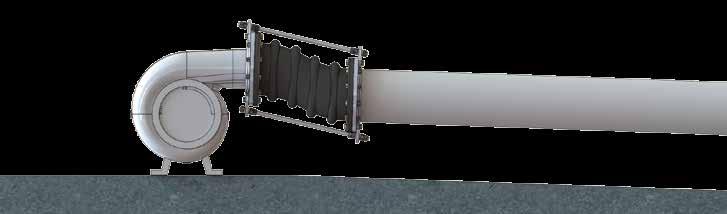

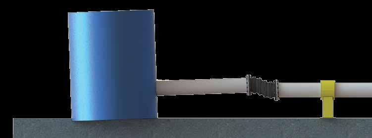

15 Settlement Layout Examples Tank Settlement Anchor Pump System Settlement 1


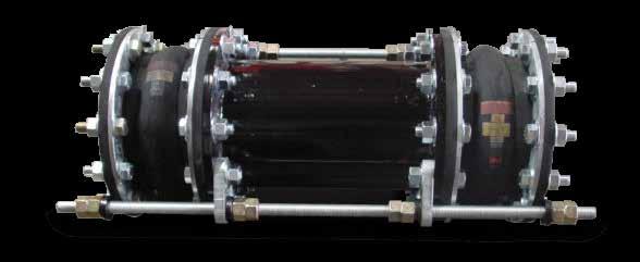

16 ALSO AVAILABLE Hinged Assembly Tied Rod Assembly
Series 230 Rubber Joints
 Series 230 Rubber Joints Series 230 Rubber Expansion Joints are designed for piping systems to absorb pipe movements, relieve stress, reduce system noise/vibration, compensate for misalignment/offset and
Proco Series 230 Rubber Joints
 Proco Series 230 Rubber Joints Proco Series 230 Rubber Expansion Joints are designed for piping systems to absorb pipe movements, relieve stress, reduce system noise/vibration, compensate for misalignment/offset
Proco s Headquarters. Largest Inventory of Expansion Joints and Check Valves
 Proco s Headquarters Largest Inventory of xpansion Joints and Check Valves 1 Proco Style RC & R Rubber Joints Proco Style RC & R Rubber xpansion Joints are designed for piping systems to absorb pipe movements,
Proco Style 240/242 Molded Spherical Joints
 Proco Style /22 Molded Spherical Joints Proco Style /22 Spherical Molded Expansion Joints are designed for piping systems to absorb pipe movements, relieve stress, reduce system noise/vibration, compensate
Proco Style 240 Molded Spherical Joints
 Proco Style Molded Spherical Joints Proco Style Spherical Molded Expansion Joints are designed for piping systems to absorb pipe movements, relieve stress, reduce system noise/ vibration, compensate for
Proco Style 240/242 Molded Spherical Joints
 Proco Style /22 Molded Spherical Joints Proco Style /22 Spherical Molded Expansion Joints are designed for piping systems to absorb pipe movements, relieve stress, reduce system noise/vibration, compensate
Proco Style 242 Molded Spherical Joints
 Proco Style 22 Molded Spherical Joints Proco Style 22 Spherical Molded Expansion Joints are designed for piping systems to absorb pipe movements, relieve stress, reduce system noise/ vibration, compensate
Proco Series 260R Molded Wide Arch Expansion Joints
 Proco eries 260R Molded Wide Arch Expansion Joints Proco eries 260R Molded Wide Arch Expansion Joints are specifically designed for use with Plastic or FRP Piping ystems. An option for the standard spool-type
Installation, operation & maintenance manual Integral Tie Rod Design
 Installation, operation & maintenance manual Integral Tie Rod Design Date: 2431 North Wigwam Dr. Stockton, CA 95205 Phone: 800-344-3246 Fax: 209-943-0242 Email: sales@procoproducts.com Table of Contents
Installation, Operation & Maintenance Manual RC/RE Series
 Document Title Installation, Operation & Maintenance Manual RC/RE Series Date: 2431 North Wigwam Dr. Stockton, CA 95205 Phone: 800-344-3246 Fax: 209-943-0242 Email: sales@procoproducts.com Table of Contents
Installation, operation & maintenance manual
 Installation, operation & maintenance manual 2431 North Wigwam Dr. Stockton, CA 95205 Phone: 800-344-3246 Fax: 209-943-0242 Email: sales@procoproducts.com Table of Contents 1.0 Introduction 2 2.0 Storage
SERIES ASM NEOPRENE/EPMD FLANGED SINGLE SPHERE CONNECTOR CONNECTORS. Pressures to 225 PSIG (15.51 barg) Temperatures to 230ºF (110ºC)
 Temperatures to 230ºF (110ºC)") CONNECTORS APPLICATIONS Process Industry Weak Acids Alkalies Compressed Air Pulp & Paper MODELS ASM - Flanged Connection OPTIONS Control Rods Oil & Gas Water & Waste Pump suction & discharge Sea water
CONNECTORS APPLICATIONS Process Industry Weak Acids Alkalies Compressed Air Pulp & Paper MODELS ASM - Flanged Connection OPTIONS Control Rods Oil & Gas Water & Waste Pump suction & discharge Sea water
Installation, Operation & Maintenance Manual
 Installation, Operation & Maintenance Manual Style 240/242 Date: 2431 North Wigwam Dr. Stockton, CA 95205 Phone: 800-344-3246 Fax: 209-943-0242 Email: sales@procoproducts.com Table of Contents 1.0 Introduction:
Proco Series 300 Flagged Rubber Pipe Connectors
 Proco Series 0 Flagged Rubber Pipe Connectors PROCO Series 0 Rubber Pipe is designed for tough demanding industrial and commercial applications as found in: Chemical-Petrochemical and Industrial Process
EXPANSION JOINT SELECTION GUIDE
 EXPANSION JOINT SELECTION GUIDE The proper selection and application of an expansion joint is the determining factor in its operation and life. Improper selection and application will lead to problems
SERIES ASM NEOPRENE/EPMD FLANGED SINGLE SPHERE CONNECTOR CONNECTORS. Pressures to 225 PSIG (15.51 barg) Temperatures to 230ºF (110ºC)
 Temperatures to 230ºF (110ºC)") CONNECTORS APPLICATIONS Process Industry Weak Acids Alkalies Compressed Air Pulp & Paper MODELS ASM - Flanged Connection OPTIONS Control Rods Oil & Gas Water & Waste Pump suction & discharge Sea water
CONNECTORS APPLICATIONS Process Industry Weak Acids Alkalies Compressed Air Pulp & Paper MODELS ASM - Flanged Connection OPTIONS Control Rods Oil & Gas Water & Waste Pump suction & discharge Sea water
- METALLIC EXPANSION JOINTS
 EXPANSION JOINTS FOR PIPING SYSTEM - METALLIC EXPANSION JOINTS - NON METALLIC EXPANSION JOINTS EXPANSION JOINTS FOR PIPING SYSTEM - METALLIC EXPANSION JOINTS - NON METALLIC EXPANSION JOINTS - EXPANSION
FAX: SPECIAL APPLICATION HOSES, METAL & TEFLON HOSES
 Large Bore Teflon Fittings Selection Pipe Thread (NPT) Style 03 Flanges Lap Joint Flange Style 12 Shown with epoxy coated steel flange Cam and Groove Female Swivel Type Style 16 Also available Teflon Encapsulated
TO BE FUNISHED WITH CONTROL UNITS YES NO MOVEMENT CAPABILITY AND FORCES. Elong. (in) Approx Force (Lbs)
 Approx Force (Lbs)") This flexible joint should be installed the length shown on drawing. Piping and equipment connected by this flexible joint must be anchored and guided. If not, control units must be used to prevent movement
This flexible joint should be installed the length shown on drawing. Piping and equipment connected by this flexible joint must be anchored and guided. If not, control units must be used to prevent movement
Rubber Expansion Joints
 Rubber Expansion Joints ENGINEERED EXPANSION JOINTS Rubber Expansion Joints MACOGA has more than 40 years of experience in expansion joints and offers the most complete range ever concerning sizes, material,
DESIGN CONSIDERATIONS
 PRESSURE THRUST DESIGN CONSIDERATIONS APPLICATIONS Intermediate Anchor An intermediate anchor is one which divides a pipeline into individual expanding pipe sections containing multiple expansion devices
Platinum Series FEATURES: Up to 16 Stainless Steel Plies
 Maximum Vibration Absorption Longest Cycle Life Soft Spring Rate = Ease of Installation Maximum Safety Platinum Series Series 151-1215 Welded Fixed Flange Series 150-TR-2115 Van Stone Floating Flange Keflex
CPF INSTALLATION, OPERATION, AND MAINTENANCE MANUAL FLANGED SERIES CHECK VALVE *
 CPF INSTALLATION, OPERATION, AND MAINTENANCE MANUAL FLANGED SERIES CHECK VALVE * Elasto-Valve s CPF Series is a flanged, bolt-on duckbill Check Valve manufactured with top quality elastomeric materials.
Style 234 Restrained Flexible Single-Gasket Coupling. System No. Submitted By Spec Sect Para Location Date Approved Date
 Victaulic Bolted Split-Sleeve Products (VBSP) Style 234 carbon steel couplings (formerly Depend-O-Lok Air/FluidMaster) are single-arch couplings that are commonly used in buried or exposed steel pipe applications
Series 3500 Externally Pressurized Expansion Joints Catalog 574 H
 Series 3500 Externally Pressurized Expansion Joints Catalog 57 H 500 Laminated Bellows Expansion J Series 3500 on Joints Externally Pressurized Expansion Joints Standard Designs Sizes " through ", 50 &
FIG Gruvlok Flanges
 Gruvlok Flanges The Gruvlok Fig. 7012 Flange allows direct connection of Class 125 or Class 150 flanged components to a grooved piping system. The two interlocking halves of the 2" thru 12" sizes of the
A joint reliance. SJT series METAL EXPANSION JOINT SJT-0107
 A joint reliance SJT series METAL EXPANSION JOINT S J T SJT-0107 SJT series METAL EXPANSION JOINT FEATURES Bellow Expansion Joints are employed in piping systems to absorb differential thermal expansion
Type B (Extruded Branch) Sizes 4 through 30
 Sizes 4 through 30") STOPPLE Fittings & Reduced Branch Split Tees, Sizes 4-inch and Larger Bulletin No: 1100.001.05 Date: July 2008 Cross Indexing No: n/a Supersedes: 1100.001.04 (07/06) Typical Tapping Setup For Plugging
STOPPLE Fittings & Reduced Branch Split Tees, Sizes 4-inch and Larger Bulletin No: 1100.001.05 Date: July 2008 Cross Indexing No: n/a Supersedes: 1100.001.04 (07/06) Typical Tapping Setup For Plugging
SCOPE OF WORK WASTEWATER TREATMENT PLANT THE WORLD LEADER IN PIPE JOINING SOLUTIONS
 SCOPE OF WORK WASTEWATER TREATMENT PLANT THE WORLD LEADER IN PIPE JOINING SOLUTIONS THE VICTAULIC DIFFERENCE HOUSING GROOVE GASKET BOLT/NUT GROOVE GROOVED PIPE JOINING TECHNOLOGY How does it work? The
MCF BALL VALVES OVERVIEW
 MCF BALL VALVES OVERVIEW ISSUED JULY 2014 MCF BALL VALVES OVERVIEW THE CENTER OF MCF MODULAR THREE-PIECE VALVE CONSTRUCTION, ISO 5211 TYPE BODY CONFIGURATION, ACCOMMODATES A WIDE CHOICE OF SEATS, SEALS,
Innerlynx Type UL Fire Rated 3Hour Fire Stop ADVANCE PRODUCTS & SYSTEMS, INC. ISO-9001 CERTIFIED COMPANY - FM
 Innerlynx Type UL Fire Rated 3Hour Fire Stop ADVANCE PRODUCTS & SYSTEMS, INC. ISO-9001 CERTIFIED COMPANY - FM53705 www.apsonline.com Why choose Innerlynx? offer 21 different sizes for all pipe diameters
RUBBER BELLOWS general
 RUBBER BELLOWS general Our rubber compensators are made from various elastomers and provide the flexible element in pipework that is indispensable in todays technically advanced plant and machinery installations.
Expansion & contraction
 Expansion & contraction All materials expand & contract with thermal change & pressure change. In case of piping systems, this dimension change can produce excessive stresses throughout the piping system
F low L ine 72/73 Wafer & Lug Style Sizes 2-24
 F low L ine 72/73 Wafer & Lug Style Sizes 2-24 Cartridge Seated Butterfly Valves KEY FEATURES Body One piece wafer and lugged body for strength and stability in extreme environments Wafer bodies have a
KEYSTONE SERIES 320 BUTTERFLY VALVES INSTALLATION AND MAINTENANCE INSTRUCTIONS
 Before installation these instructions must be fully read and understood HAZARD POTENTIALS disregarding of instructions improper use of product insufficiently qualified personnel Valve application to be
Keystone Series GR resilient seated butterfly valves GRW/GRL Installation and operation manual
 Before installation these instructions must be fully read and understood Important Before valves are installed or used the following actions are recommended. 1. Valves/parts have to be inspected and thoroughly
CompoSeal butterfly valves, wafer style Installation & Maintenance Instructions
 Please read these instructions carefully This symbol indicates important messages and safety instructions. Intended valve use The valve is intended to be used only in applications within the pressure/temperature
5. STRAUB-FLEX / STRAUB-REP
 5. STRAUB-FLEX / 5.1 STRAUB-FLEX For gas and water supply, sewage treatment, industrial plants, power plants and shipbuilding: STRAUB- FLEX is the optimal pipe joint. Suitable for suction or pressure lines,
Copper Axial Expansion Joint
 For Technical Assistance and Sales Contact: FlexEJ Ltd Tel: +44 (0) 1384 881188 Email: sales@flexej.co.uk Fax: +44 (0) 1384 896875 Web: www.flexej.co.uk Section 4 Copper Axial Expansion Joint FlexEJ Small
411 Steel Couplings Material Specifications
 411 Steel Couplings Material Specifications Gasket Material Specifications STANDARD: Nitrile (Buna-N)-NSF 61 Compounded to produce superior storage and performance characteristics while resisting water,
Installation Operation Maintenance
 Installation Operation Maintenance www.challengervalves.com.au 1 QAD#IM1015 REVC 3.10.15 Index 1. INTRODUCTION 3 1.1 Design Features 1.2 Flange and Pipe Compatibility 3 1.3 Operating Pressures and Temperatures
Flanged. Standard Single Hinge. Product Nº : SHF/16/001. For more information please call our sales engineers on
 Product Nº : SHF/16/001 Standard Single Hinge Flanged Design ConDitions Max. Design Pressure 16 Bar Max. Design Temperature 300ºC Test Pressure Bellow Options End Fittings and Brackets Options Optional
RANGER FLANGE ADAPTORS
 RANGER ADAPTORS RANGER products, in the form of wide range couplings and flange adaptors, are designed to join pipes of various outside diameters with the same or different nominal bore. Because of the
KEYSTONE OPTISEAL F14/16-15/17 AND BREWSEAL BUTTERFLY VALVES INSTALLATION AND MAINTENANCE INSTRUCTIONS
 Before installation these instructions must be fully read and understood 4. Ozone: storage rooms should not contain any equipment generating ozone. E.g. lamps, electric motors. IMPORTANT Before valves
QuickFit. Simple. Couplings & Flange Adaptors. Pioneers in pipe solutions. Close Tolerance Preassembled Fittings
 Simple QuickFit Couplings & Flange Adaptors Close Tolerance Preassembled Fittings Pioneers in pipe solutions QuickFit Overview Dedicated Couplings & Flange Adaptors The QuickFit coupling range is designed
FIG Gruvlok Flange Adapter
 FIG. 88 Gruvlok Adapter The Gruvlok Fig. 88 Adapter allows for direct connection of Class 125 or Class 150 flanged components to a grooved piping system. The Gruvlok Adapter provides an alternative method
STOPPLE Plus Fittings
 STOPPLE Plus Fittings Sizes: 4- Through 36-inch Bulletin No: 1100.007.02 Version: 08.2014 Cross Indexing No: n/a Supercedes: 1100.007.01 (06.2014) Offset in closeup Options Description STOPPLE Plus fittings
THOMAS. Unifit Premier Series. Couplings & Flange Adaptors Non Restrained Products PIPE PRODUCTS
 THOMAS Couplings & Flange Adaptors Non Restrained Products PIPE PRODUCTS Unifit Premier Series Universal Pipe Couplings and Flange Adaptors for all Rigid Pipe J1 Unifit Premier Series Application Locally
High Performance Butterfly Valves
 Tech Bulletin Page 500-11 MAX SEAL HP SERIES High Performance Butterfly Valves Available with Soft and Metal Seating MODEL BL630 Size Range 2 thru 24, optional thru 120 ANSI Class 150//600/900 20 Lug 6
Expansion Joint. Ball Joint Flexible Joint
 Ball Joint Flexible Joint 255 Selection Ball Joint Selection Flexible Joint Selection 0.98 1.0 2.0 274 274 276 276 275 275 EB-1J EB-2J ES-10 ES-11 EB-11 EB-12 Type Bellows Sleeve Max. Pressure (MPa) 10
BUTTERFLY VALVES. An industry leader in underground and in-plant applications. STYLE STYLE Consult factory for sizes
 An industry leader in underground and in-plant applications. BUTTERFLY VALVES STYLE 4500 3 24 STYLE 1450 30 54 Consult factory for sizes 60 120 C504 Class 150B & 250B M&H Valve is a division of McWane,
PVC & CPVC Copper Tubing. Insulated Pipe Steel Conduit. Plastic Conduit SDR-35. Dual Containment Glass Pipe
 Why choose Innerlynx? Innerlynx offer 21 different sizes for all pipe diameters ranging from 1. Innerlynx are made from synthetic rubbers with industrial strength UV and ozone resistant plastic or all
RESILIENT SEATED BUTTERFLY VALVES
 DESIGN FEATURES APPLICATIONS: HVAC Chemical/Petrochemical Processing Food and Beverage Industry Power and Utilities Pulp and Paper Industry Stem Configuration: Gives positive attachment for handles or
TEL: Version: KW2
 WWW.KLAMBON.COM 1 Page Klambon Water is a wholly owned subsidiary of West Rand Engineering (WRE), we are suppliers of valves, fittings and related products to all industries and our service extends to
KEYSTONE. Butterfly valves Figure 9 Installation & Maintenance Instructions. Please read these instructions carefully
 KEYSTONE Please read these instructions carefully This symbol indicates important messages and safety instructions. Hazard potentials: disregarding of instructions improper use of product insufficiently
PRODUCT CATALOGUE. PisaFlex is Mexico s premier manufacturer of metallic expansion joints and braided hose assemblies.
 PRODUCT CATALOGUE PisaFlex is Mexico s premier manufacturer of metallic expansion joints and braided hose assemblies. PisaFlex is qualified to Manufacture product to ASME U Stamp. PISAFLEX / PRODUCT CATALOGUE
Vickers 45. VMQ Series 30 Vane Pumps. Fixed Displacement, For Industrial and Mobile Applications (4.188)
") [ (4.188) 49,4 (1.94) /21,8 /.86) 174,7/172,3 (6.88/6.78) 332,9/33,5 (13.11/13.1) "M" is marked if metric port threads No marking if inch port threads AS-568-152 O-ring Vickers 45 65,3 (2.57) 13 (5.1 VMQ
[ (4.188) 49,4 (1.94) /21,8 /.86) 174,7/172,3 (6.88/6.78) 332,9/33,5 (13.11/13.1) "M" is marked if metric port threads No marking if inch port threads AS-568-152 O-ring Vickers 45 65,3 (2.57) 13 (5.1 VMQ
BEARINGS The lower bearing assemble is constructed to allow continuous operation when fully submerged in wastewater.
 GENERAL SPECIFICATION INTENT The equipment to be supplied by manufacturer includes the screw pumps, support for the drive unit, profile plates, motors, gearboxes, couplings, guards, upper and lower bearing
Butterfly valves Figure 56 Installation & Maintenance Instructions
 KEYSTONE Please read these instructions carefully This symbol indicates important messages and safety instructions. Hazard potentials: disregarding of instructions improper use of product insufficiently
VSI, LLC SERIES 2100 RESILIENT SEATED BUTTERFLY VALVES INSTALLATION, OPERATION AND MAINTENANCE MANUAL
 VSI SERIES 2100 RESILIENT SEATED BUTTERFLY VALVES VSI, LLC. 2-0 SERIES 2100 RESILIENT SEATED BUTTERFLY VALVES INSTALLATION, OPERATION AND MAINTENANCE MANUAL Publication: V2100- August 2016 TABLE OF CONTENTS
310 Wafer high performance butterfly valve 312 Lugged high performance butterfly valve
 310 Wafer high performance butterfly valve 312 Lugged high performance butterfly valve Features and Benefits Uninterrupted gasket surfaces help eliminate problems associated with seat retaining screws
Keystone Figures 310/312 K-LOK Butterfly Valves
 310 - Wafer high performance butterfly valve 312 - Lugged high performance butterfly valve Features General Application High performance applications such as steam, chill water, water, utility lines, gasoline,
CLARKSON URETHANE KNIFE GATE VALVES FIGURE SU10R
 CLARKSON URETHANE KNIFE GATE VALVES Installation and maintenance instructions for field replaceable urethane lined knife gate valves GENERAL INFORMATION The Clarkson SU10R knife gate valve offers bi-directional
Installation Operation Maintenance. LSSN Butterfly Valve AGA Approved 50MM - 150MM. QAD#IM6055.REVA
 LSSN Butterfly Valve Installation Operation Maintenance Licence Number: 5326 www.challengervalves.com.au 1 Index 1. INTRODUCTION 1.1 Design Features 3 1.2 Flange and Pipe Compatibility 4 1.3 Operating
McCannalok HIGH PERFORMANCE BUTTERFLY VALVE OPERATION AND MAINTENANCE MANUAL. The High Performance Company
 McCannalok HIGH PERFORMANCE BUTTERFLY VALVE OPERATION AND MAINTENANCE MANUAL The High Performance Company Table of Contents Safety Information - Definition of Terms... 1 Introduction... 1 Installation...
KEYSTONE FIGURES 310/312 K-LOK BUTTERFLY VALVES
 310 - Wafer high performance butterfly valve 312 - Lugged high performance butterfly valve FEATURES GENERAL APPLICATION High performance applications such as steam, chill water, water, utility lines, gasoline,
Keystone Butterfly valves ParaSeal Installation and maintenance instructions
 Before installation these instructions must be fully read and understood Please read these instructions carefully Hazard potentials: disregarding of instructions improper use of product insufficiently
PRODUCT CATALOG TPS UNI-COUPLING. Your repair is our care
 PRODUCT CATALOG TPS Your repair is our care UNI-COUPLING HIGH FLEXIBILITY AND SAFETY MARGINS DETERMINE THE BASIC PRINCIPLE OF UNI-COUPLING Two types of UNI-Coupling UNI-Coupling applies one unique technical
ONYX VALVE CO MODEL GSF AND GSD Installation & Maintenance
 ONYX VALVE CO MODEL GSF AND GSD Installation & Maintenance Operation: (04-2011) The Onyx Series GSF and GSD valves operate very simply. Injecting compressed air into the iron housing collapses the rubber
argco.com
 800-854-1015 argco.com STRUT SUPORT SYSTEM STRUT SUPPORT CHANNEL US Strut Support Channel Quick, strong attachment of single or multiple pipes horizontally or vertically Unlimited applications - range
Wafer Silent Check Valves
 Applications Liquid Service Metals & Mining Process Industry Water & Waste Water Power Industry Pulp & Paper Chemical Industry Oil & Gas Wafer Silent Check Valves Pressures to 740 PSIG Temperatures to
PROJ. NO SECTION HYDRONIC PUMPS
 SECTION 23 21 23 HYDRONIC PUMPS PART 1 - GENERAL 1.1 RELATED DOCUMENTS A. Drawings and general provisions of the Contract, including General and Supplementary Conditions and Division 01 Specification Sections,
Bray/Mckannalok Butterfly Valve Series 40/41/42/43/44/45 Installation Manual Technical Bulletin No Date: May 2004/Page 1 of 6
 Date: May 2004/Page 1 of 6 Bray/McCannalok Butterfly Valves Installation and Maintenance Instructions ANSI Classes 150 and 300 - Sizes 2-1/2 through 24 ANSI Classes 600 - Sizes 3 through 16 Bidirectional
310 Wafer high performance butterfly valve 312 Lugged high performance butterfly valve
 310 Wafer high performance butterfly valve 312 Lugged high performance butterfly valve Features and Benefits Uninterrupted gasket surfaces help eliminate problems associated with seat retaining screws
Keystone Figure 85/86 Check valves Installation and Maintenance Instructions
 Please read these instructions carefully 1.3 Handling 1.3.1 Packed valves Lifting and handling of the packed valves in crates should be carried out by appropriate lifting equipment. If a fork lift truck
Manually Operated Diaphragm Valves
 Manually Operated Diaphragm Valves Page 1 of 7 OPERATING PRESSURE AND TEMPERATURE Non-shock pressure at temperature range Non-shock pressure at max. temperature ½ -2 (DN15-DN50) 230 psig from 0ºF to 100ºF
COB ADVANTAGES Quality, lightweight, durable nylon. 20% lighter than metal. Tough/shatter-proof and easily cleaned and maintained,
 LOW PRESSURE NYLON EXPANSION PLUGS 0.5 to 6 CAST ALUMINUM EXPANSION PLUGS 1 1/2 TO 36 These superior, versatile, expandable plugs are used to accommodate a wide variety of industrial applications where
Ford Fabricated Steel Products
 Ford Fabricated Steel Products Section N2 12/2000 The Ford Meter Box Co., Inc. 775 Manchester Avenue, P.O. Box 443, Wabash, Indiana, USA 46992-0443 Telephone: 219/563-3171 FAX: 1-800-826-3487 Overseas
Expansion Joints Guide Module 2a - Axial Expansion Joints General - Standard Program (EFB) - Installation Instructions
 - Installation Instructions") Expansion Joints Guide Module 2a - Axial Expansion Joints General - Standard Program (EFB) - Installation Instructions BOA Expansion Joints Guide Expansion Joints Guide Summary Module 2a 1 AXIAL EXPANSION
Expansion Joints Guide Module 2a - Axial Expansion Joints General - Standard Program (EFB) - Installation Instructions BOA Expansion Joints Guide Expansion Joints Guide Summary Module 2a 1 AXIAL EXPANSION
expansion joints metal bellows Traditions Will Never Mean Limits. Form and Function. Anything Worth Doing is Worth Doing Right.
 Flexcomp Flexpress Bellowsflex Pumpflex BellowsXhaust Guideline Traditions Will Never Mean Limits. We understand that no customer s requirements are exactly the same. That our audience is targeted to engineers/designers
Recommended BFV Installation, Maintenance & Repair Procedures Ultraflo 300 & 400 Series Valves
 I. Introduction Recommended BFV Installation, Maintenance & Repair Procedures Ultraflo 300 & 400 Series Valves A. Butterfly Valve Seat / Disc Function The seat in most resilient-seated butterfly valves
INSTALLATION, OPERATION AND MAINTENANCE FOR SERIES 500 K-FLO BUTTERFLY VALVES
 INSTALLATION, OPERATION AND MAINTENANCE FOR SERIES 500 K-FLO BUTTERFLY VALVES PO Box 411 Berwick PA 18603 800-247-VALV www.crispinvalve.com Product Introduction -- K-FLO Series 500: 3 --20 Introduction
MK Series - High Performance Butterfly Valves Operation and Maintenance Instructions
 COMMERCIAL Bray Controls Commercial Division 13788 West Road, Suite 200A Houston, Texas 77041 BCDSales@Bray.com Phone: 1-888-412-2729 Fax: 1-888-412-2720 www.braycommercialdivision.com MK Series - High
Flexider FLUID CATALYTIC CRACKING UNIT EXPANSION JOINTS INDUSTRIAL. An IMCI Company
 FLUID CATALYTIC CRACKING UNIT EXPANSION JOINTS An IMCI Company CALL TOLL FREE: 1-888-979-FLEX Design and Engineering specializes in the custom design and engineering of FCCU expansion joints. These items
KEYSTONE. Check valves Figure 85/86 Installation & Maintenance Instructions. Figure 85. Figure 86.
 KEYSTONE Please read these instructions carefully. This symbol indicates important messages and safety instructions. Hazard potentials: disregarding of instructions improper use of product insufficiently
mechanical coupling system
 mechanical coupling system R Since 1981 Depend-O-Lok has offered engineers, contractors, OEM s and system owners an improved pipeline coupling system. Depend-O-Lok products offer strength, longterm reliability,
Teguflex. Expansion joints TEGUFLEX. Expansion joints. TRELLEBORG FLUID HANDLING SOLUTIONS
 Teguflex Expansion joints TEGUFLEX Expansion joints www.trelleborg.com/fr/expansion-joints TRELLEBORG FLUID HALING SOLUTIONS Expansion joints Teguflex Functions and advantages Compensate for thermal elongation.
UNIVERSAL TIED EXPANSION JOINTS
 UNIVERSA TIED EXPANSION JOINTS Scan this QR 64 ANSI DIN EN +600 C The movements occured in two directions can only be absorbed by using Epansion Joints. Universal tied expansion joints are made up of two
Scope. Applicability. Caution. I & M CV3000 Series. Storage. Installation & Maintenance Instructions for Marwin CV3000 Series Three Piece Ball Valves
 I & M CV3000 Series 3170 Wasson Road Cincinnati, OH 45209 USA Phone 513-533-5600 Fax 513-871-0105 marwin@richardsind.com www.marwinvalve.com Installation & Maintenance Instructions for Marwin CV3000 Series
Series. Molded PTFE Expansion Joints
 Series 0 Molded PTFE Expansion Joints PROCO PRODUCTS, INC. The Expansion Joint People PROCO Products, Inc. is the leading manufacturer of rubber, TEFLON, metal, and fabric connectors and expansion joints
expansion joints rubber bellows hoses stress analysis
 expansion joints rubber bellows hoses stress analysis expansion joints rubber bellows hoses stress analysis Contents EXPANSION JOINTS UNRESTRAINED EXPANSION JOINTS Introduction 3 Axial Expansion Joint
Smith-Blair OMNI Coupling System Advantages:
 OMNI Coupling System SmithBlair s OMNI Coupling System utilizes the tremendous tensile strength of ductile iron to your best advantage. Applying the principles of space age technology to engineer the OMNI
SV SERIES. Metal Seated Ball Valves
 SV SERIES Metal Seated Ball Valves 1/2 THRU 12 ANSI 150# THRU ANSI 1500# FULL PORT AND REDUCED PORT UNI-DIRECTIONAL AND BI-DIRECTIONAL 316SS OR CARBON STEEL BODY LIVE LOADED STEM PACKING HIGH QUALITY CASTINGS
Flexible Couplings. Large Diameter Coupling. Global leaders in flexible couplings, drainage & plumbing systems. Benefits
 Flexible Couplings Large Diameter Coupling Flexseal can provide Large Diameter Couplings that are manufactured to order, thereby meeting the specific contractor and site requirements. Large Diameter Couplings
THOMAS. Unifit Series. Couplings & Flange Adaptors Non Restrained Products PIPE PRODUCTS
 THOMAS Couplings & Flange Adaptors Non Restrained Products PIPE PRODUCTS Unifit Series Universal Pipe Couplings and Flange Adaptors for all Rigid Pipe H1 COUPLINGS & FLANGE ADAPTORS - NON RESTRAINED BELLVILLE
Advantages of Grooved Fittings
 Grooved Fittings Advantages of Grooved Fittings Comparative Advantages Allows angular deflection-misalignment Expansion, contraction or, no need for expansion joint Reclaimable, no need for union Allows
Introduction to Bellows Why bellows are used in Piping System?
 Introduction to BELLOWS http://www.sigmaflexeng.com http://www.sigmaflexeng.com Manufacturers of Expansion Joints & Flexible Metal Hose Assemblies Reg. Office & Factory: 865/2 GIDC INDUSTRIAL ESTATE, MAKARPURA,
Mechanical MATERIAL SPECIFICATIONS. Stainless Steel Housing Specifications. Gasket Specifications. Bolt / Nut Specifications
 82 COUPLINGS SYSTEM The Grinnell Stainless Steel System is designed for joining 2" to 12" (54,0mm to 206,4mm) stainless steel piping, schedules 5, 10, and 40. The Figure 472 coupling patented Universal
SERIES. Table 1: Available Materials Temperatures
 PROCO 700 SERIES 1 The PROCO Series 700 ProFlex Rubber Check Valves are a cost effective way to control back pressures from sewage treatment plants, outfalls and tidal operations. They are a fully passive
Installation & Operation Manual
 Installation & Operation Manual Thank you for purchasing our AS4795.1 Butterfly Valve. Before installing or operating, please carefully read this manual to know thoroughly how to install or operate. The