FLANGE. Flanges used for
|
|
|
- Marsha Anthony
- 6 years ago
- Views:
Transcription
1 FLANGE
2 FLANGE Flanges with rating class designations 150, 300, 400, 600, 900, 1500, and 2500 in sizes NPS 1 2 through NPS 24 ASME B16.5: Pipe Flanges and Flanged Fittings (NPS 24 ) ASME B16.47: NPS 26 < Pipe Size < NPS 60
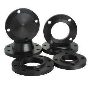
3 Flanges used for FLANGE Mate to equipment, vessels, valve, The component or pipe section must be frequently removed for service (periodic cleaning) Flanges are normally used for pipe sizes above NPS 1½. The components cannot be serviced in line. The components being joined are not capable of being welded. Quick field assembly is required.
4 Marking on Flanges: The manufacturer s name or trademark shall be applied. Materials marked with the ASTM specification grade identification symbol (letters and numbers) Pressure rating class designation (i.e., 150, 300, 400, 600, 900, 1500, or 2500). Conformance standard designation B16 or B16.5 The NPS designation Facing of Flange Heat Number FLANGE
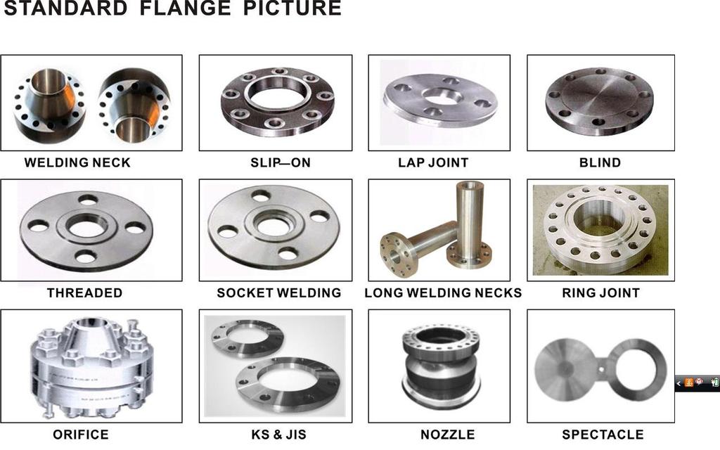
5 FLANGE Type of Flanges: The most used flange types according to ASME B16.5 are: Welding Neck flange Slip On flange Socket Weld flange Lap Joint flange Threaded flange Blind flange.

6 Type of Flanges: FLANGE
7 FLANGE Weld Neck Flange
8 FLANGE Weld Neck Flange Welding neck flanges are easy to recognize at the long tapered hub, that goes gradually over to the wall thickness from a pipe or fitting. The long tapered hub provides an important reinforcement for use in several applications involving high pressure, sub-zero and / or elevated temperatures. The smooth transition from flange thickness to pipe or fitting wall thickness effected by the taper is extremely beneficial, under conditions of repeated bending, caused by line expansion or other variable forces. This flange type will be welded to a pipe or fitting with a single full penetration, V weld (Butt weld). Continued...

9 FLANGE Weld Neck Flange Long tapered butt weld hub and the inside diameter of flange matches the inside diameter of the pipe used Preferred in an environment with extreme temperature conditions Used where we need 100% RT inspection, since joint is butt weld Continued...
10 FLANGE Weld Neck Flange
11 FLANGE Slip-On Flange Continued...
12 The connection with the pipe is done with 2 fillet welds, as well at the outside as also at the inside of the flange. Advantage: FLANGE Slip-On Flange Most commonly stocked flange due to the fact that one size fits all pipe schedules. Fabricators can more easily cut pipe to length for slipon flanges and their smaller thickness allows for easier alignment of bolting holes Continued...
13 Disadvantage: FLANGE Slip-On Flange Internal welds is slightly more subject to corrosion than the butt-weld (0 1/16 ) Strength under internal pressure is 1/3 of corresponding welding neck flange Poor resistance to shock and vibration A combination of flange and elbow or flange and tee is not possible, because named fittings have not a straight end, that complete slid in the Slip On flange. Continued...
14 FLANGE Slip-On Flange The X measure on the image, are approximately: Wall thickness of pipe + 3 mm.


15 FLANGE Slip-On Flange ASME B16.5 code limits their usage for 1500#-2500# (lbs.) applications and they are generally not preferred for high pressure temperature environments.
16 FLANGE Socket Welding Flange


17 FLANGE Socket Welding Flange The connection with the pipe is done with 1 fillet weld, at the outside of the flange. But before welding, a space must be created between flange or fitting and pipe. Socket Weld flanges were initially developed for use on small-size high pressure piping. Continued...
18 FLANGE Socket Welding Flange Advantage: These flanges fit up easily and they do not have alignment problems. This makes them widely usable for moderate services. The recess on the inside diameter allows for a good fit of the pipe allowing for a smooth flow of liquid Work well for smaller sizes and higher pressure temperature conditions. Continued...
19 FLANGE Socket Welding Flange Disadvantage: The disadvantage of this flange is the right gap, that must be made. Continued...
20 FLANGE Socket Welding Flange In assembly of the joint before welding, the pipe or tube shall be inserted into the socket to the maximum depth and then withdrawn approximately 1/16" (1.6 mm) away from contact between the end of the pipe and the shoulder of the socket. (ASME B ) The purpose for the bottoming clearance in a Socket Weld is usually to reduce the residual stress at the root of the weld that could occur during solidification of the weld metal.


21 FLANGE Socket Welding Flange

22 FLANGE Socket Welding Flange
23 FLANGE Lapped Flanges
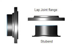
24 FLANGE Lapped Flanges Lap joint flanges have all the same common dimensions as other flanges, however it does not have a raised face, they are used in conjunction with a "Lap Joint Stub End". These flanges are nearly identical to a Slip On flange with the exception of Radius at the intersection of the flange face Bore to accommodate the flanged portion of the Stub End. Used with a matching stub-end insert Continued...
25 FLANGE Lapped Flanges These flanges slip over the pipe, and are not welded or otherwise fastened to it. Bolting pressure is transmitted to the gasket by the pressure of the flange against the back of the pipe lap (Stub End). Advantage: Recommended in applications that require frequent dismantling of the flanges and pipe Continued...
26 Disadvantage: FLANGE Lapped Flanges Not recommended in extreme pressure temperature applications Freedom to swivel around the pipe facilitates the lining up of opposing flange bolt holes. Lack of contact with the fluid in the pipe often permits the use of inexpensive carbon steel flanges with corrosion resistant pipe. In systems which erode or corrode quickly, the flanges may be recovered for re-use. Continued...

27 FLANGE Lapped Flanges Serrated Surface Finish Continued...
28 FLANGE Stub End A Stub End always will be used with a Lap Joint flange, as a backing flange. This flange connections are applied, in low-pressure and non critical applications, and is a cheap method of flanging. In a stainless steel pipe system, for example, a carbon steel flange can be applied, because they are not come in contact with the product in the pipe. Stub Ends are available in almost all pipe diameters. Dimensions and dimensional tolerances are defined in the ASME B.16.9 standard.

29 FLANGE Stub End
30 FLANGE Threaded Flange

31 FLANGE Threaded Flange
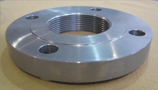
32 FLANGE Threaded Flange Can be attached to the pipe without welding Sometimes a seal weld is also used in conjunction with the threaded connection. The pipes to be attached are completely recovered during the process of dismantling. Ideal for higher pressure and temperature applications for small pipe sizes Not recommended for larger loads, especially when subjected to higher torque Continued...
33 A threaded flange or fitting is not suitable for a pipe system with thin wall thickness, because cutting thread on a pipe is not possible. Thus, thicker wall thickness must be chosen What is thicker? FLANGE Threaded Flange ASME B31.3 Piping Guide says: Where steel pipe is threaded and used for steam service above 250 psi or for water service above 100 psi with water temperatures above 220 F, the pipe shall be seamless and have a thickness at least equal to schedule 80 of ASME B Continued...

34 FLANGE Threaded Flange

35 FLANGE Threaded Flange

36 FLANGE Blind Flange

37 FLANGE Blind Flange
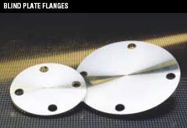
38 FLANGE Blind Flange Blind Flanges are manufactured without a bore and used to blank off the ends of piping, Valves and pressure vessel openings. Suitable for a wide variety of pressure temperature environments Continued...

39 FLANGE Blind Flange Blind Flange with Opening for Flow Out
40 Special Flanges are basically identical to standard flanges, but have a number of special features. Other Special Types: Split Flange Reducing Flange Long Welding Neck flange Orifice Flange Weldoflange / Nipoflange Expander Flange Jack Screw Flange Flangeolet Spectacle Blind SPECIAL FLANGES Continued...

41 SPECIAL FLANGE Split Flange Continued...
42 Split Flange SPECIAL FLANGE Split Flange Used for reinforcing the weak areas of the piping system. They consist of two interlocked parts that contributes to the secure and easy installation of these split flanges on pre existing pipelines. Continued...


43 SPECIAL FLANGE Split Flange Continued...

44 SPECIAL FLANGE Reducing Flange
45 SPECIAL FLANGE Reducing Flange Reducing Flanges are suitable for changing line size A reducing flange consists of a flange with one specified diameter having a bore of a different and smaller, diameter. Except for the bore and hub dimensions, the flange will have dimensions of the larger pipe size.
46 SPECIAL FLANGE Reducing Flange Specify by size of smaller pipe and outside diameter of flange to be mate» RED FLG 4 11 Should not be used if abrupt transition of size would create undesirable turbulence as at pump

47 SPECIAL FLANGE Long Welding Neck flange
48 SPECIAL FLANGE Long Welding Neck flange Long Neck Welding (abbreviated LWN) flanges are similar to a standard Welding Neck flange, but the "Neck" is considerably longer. This type is often used as a nozzle for a barrel or column.

49 SPECIAL FLANGE Long Welding Neck flange

50 SPECIAL FLANGE Orifice Flange Provision for outlet
51 SPECIAL FLANGE Orifice Flange Orifice Flanges are used with orifice meters for the purpose of measuring the flow rate of either liquids or gases in the respective pipeline. Available with raised face or RTJ face Same as weld neck and slip-on flanges with extra machining. The additional bolts act as a jack to allow the separation of the two flanges to change the orifice plate or for other inspection services. Continued...

52 SPECIAL FLANGE Orifice Flange Orifice
53 SPECIAL FLANGE Orifice Flange Continued...

54 SPECIAL FLANGE Weldoflange / Nipoflange
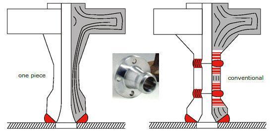
55 SPECIAL FLANGE Weldoflange / Nipoflange The Weldoflange and Nipoflange is a combination of a Welding Neck flange and a supposedly Weldolet or Nipolet. The 2 components are manufactured in one piece, and not welded. These flanges are primarily in Branch connections.

56 SPECIAL FLANGE Expander Flange
57 SPECIAL FLANGE Expander Flange Reducer + welding neck flange Expander Flanges is a Welding Neck pipe flange where the nominal size of the non-flanged end is larger than the nominal size of the flanged end. They can be used to change the size of a pipe run. These are usually used to increase the line

58 SPECIAL FLANGE Expander Flange This is an alternative to using a separate reducer and weld neck flange combination. The expander flange can be used to connect pipe to pumps, compressors and Valves.
59 SPECIAL FLANGE Jack Screw Flange Flange with jack screw

60 Flageolet SPECIAL FLANGE Flageolet

61 FLANGE Spectacle Blind Continued...
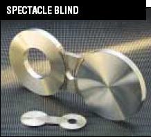
62 FLANGE Spectacle Blind Also known as a figure-8 blind Spectacle Blinds are generally applied to permanently separating pipes systems, or just to connect with each other. A Spectacle Blind is a steel plate cut into two discs of a certain thickness. The two discs are attached to each other by section of steel similar to the nose piece of a pair of glasses. One of the discs is a solid plate, and the other is a ring, whose inside diameter is equal to that of a flange. Continued...
63 FLANGE Spectacle Blind Fit between two pipe flanges and usually sandwiched between two gaskets One end of the blind will have an opening to allow flow through the pipe during operation and the other end is solid to block flow during maintenance Equipment is properly and securely blanked off with no possibility of any flow or leakage through a valve during maintenance (Positive Isolation) Continued...


64 SPECIAL FLANGE Spectacle Blind

65 SPECIAL FLANGE Spade

66 SPECIAL FLANGE Spacer
67 SPECIAL FLANGE Spade / Spacer Spades and Ring Spacers are basically the same as Spectacle Blinds, except that both are not attached to each other. So as for the Spectacle Blind already described, maintenance on a pipesystem can be a reason to temporarily replace a Ring Spacer for a Spade. By loosening of all bolts, and half of the bolts temporarily remove, the Spade or Spacer can be placed. After replacing the gaskets (new gaskets are to recommend), the bolts can be re-assembled and tightened.


68 SPECIAL FLANGE Spade/ Spacer Handle is solid for Spade and hole will be there in handle for Spacer for easy identification while in service

69 Flange Facing Types Flat Face Raised Face Ring Joint Male-Female Tongue and Groove Groove to Flat FLANGE Facing

70 FLANGE FACING Flat
71 Flat Face FLANGE FACING Flat Mating faces of both flanges are flat Gasket may be ring type, or full face, which covers the entire face both inside and outside the bolts

72 FLANGE FACING Raised
 (Fig 1) In Pressure Classes 400, 600, 900, 1500 & 2500 Lbs, the height of raised face is approximately 6.")
73 FLANGE FACING Raised In Pressure Classes 150 and 300 Lbs, the height of raised face is approximately 1.6 mm (1/16 inch) (Fig 1) In Pressure Classes 400, 600, 900, 1500 & 2500 Lbs, the height of raised face is approximately 6.4 mm (1/4 inch) (Fig 2)

74 Raised Face FLANGE FACING Raised Mating face is flat, but the area inside the bolt holes is raised 1/16" or 1/4" Gasket is usually ring type, entirely within bolts

75 FLANGE FACING Ring Joint

76 FLANGE FACING Ring Joint Both flange faces have matching flat-bottomed grooves with sides tapered from the vertical at 23º Gasket seats on flat section of flange between bore and ring joint groove Garlock spiral wound gaskets can replace solid metal ring gaskets

77 FLANGE FACING Tongue and Groove
78 FLANGE FACING Tongue and Groove Tongue and Groove Facing Groove depth is equal to or less than tongue height Groove usually not over 1/16" wider than tongue Gasket dimensions will match tongue dimensions
79 FLANGE FACING Male-Female Facing Male-Female Facing Depth of female (recessed) face normally equal to or less than height of male (raised) face, to prevent metal-to-metal contact during gasket compression Recessed O.D. normally is not more than 1/16" larger than the O.D. of the male face
80 FLANGE FACING M&F and T&G Advantages and disadvantages of Tongue & Groove and Male & Female flange faces Advantages: Better sealing properties Disadvantages: Commercial availability and cost.

81 FLANGE FACING Groove to Flat Groove to Flat Facing One flange face is flat, the other is recessed For applications requiring accurate control of gasket compression Only resilient gaskets are recommended spiral wound, hollow metal O-ring, pressure-actuated, and metal-jacketed gaskets

82 FLANGE FACING Finishing A serrated finish, either concentric or spiral, is required with 30 to 55 grooves per inch and a resultant roughness between 125 and 500 micro inches. This allows for various grades of surface finish to be made available by flange manufactures for the gasket contact surface of metal flanges.

83 FLANGE FACING Finishing The most used Surfaces


84 FLANGE BOLT HOLES For a vertical flange face (the flange face in the vertical and the line is horizontal) the bolt holes want to be orientated to straddle the vertical and horizontal centre lines.


85 FLANGE BOLT HOLES For a horizontal flange face (the flange face is horizontal and the line is vertical above or vertical down) the bolt holes want to be orientated to straddle the Plant North centre lines.
86 FLANGE Dimensions
87 FLANGE Dimensions From ASME B16.5
88 FLANGE Dimensions
89 PRESSURE TEMPERATURE RATING Flange Rating Class: Pressure/Temperature combinations Normally used classes (150, 300, 400, 600, 900, 1500, 2500) Flange strength increases with class number The material specifications are grouped within Material Group Numbers. Continued...
90 PRESSURE TEMPERATURE RATING For remaining group of material, Refer ASME B16.5 Continued...

91 PRESSURE TEMPERATURE RATING Continued...

92 PRESSURE TEMPERATURE RATING Continued...

93 PRESSURE TEMPERATURE RATING
94 FLANGE Equipment Nozzle
95 FLANGES
96 FLANGED FITTINGS
97 FLANGED FITTINGS


98 BOLT Bolt type: Stud Bolt Easily remove if corroded Material can be readily made Machine bolt Has to be strong enough to seat the gasket
99 BOLT
100 BOLT

101 BOLT - Grade

102 BOLT For Flange (ASME Class 150)
103 BOLT For Flange (ASME Class 300)

104 BOLT For Flange (ASME Class 600)
105 BOLT For Flange (ASME Class 900)
106 BOLT For Flange (ASME Class 1500)
107 TORQUE TIGHTENING
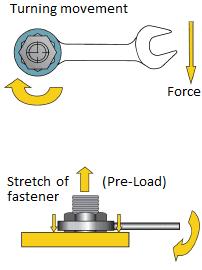
108 TORQUE TIGHTENING
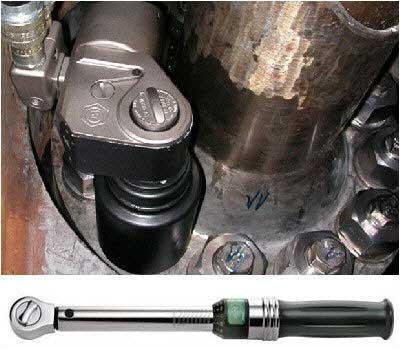
109 TORQUE TIGHTENING

110 IMPROPER BOLT LENGTH Improper flange connections - the bolts are too short
Buttweld. Pipe Fittings NOTE: ANSI B16.9, MSS-SP-43
 Buttweld Pipe Fittings NOTE: ANSI B16.9, MSS-SP-43 Buttweld fittings in duplex and other special alloys are available from stock and throughout our worldwide network of suppliers. and eccentric reducers,
FLANGES PRODUCT: STANDARD FLANGE CLASSIFICATION: PRESSURE CLASS CLASIFICATION:
 FLANGES Gestión de Compras manufactures and supplies flanges according to standards ANSI, BS, DIN, JIS and ISO as well as according to customer specifications. PRODUCT: Flanges are a pipe fitting which
Class 300, Welding Neck, Slip-On and Threaded B16.47, Ser. A. ASME B16.5 Flanges
 Class 300,, Slip-On and Threaded B16.47, Ser. A ASME B16.5 Flanges Weld, Slip-On, Socket Weld, Threaded, Lap Joint, Blind. 1/2" - 24" Class 150, 300, 400, 600, 900, 1500 and 2500 NOTE: Reducing flanges
Long Welding Neck Flanges Catalogue
 Hydraulic & Offshore Supplies Long Welding Neck Flanges Catalogue YOUR GATEWAY TO GLOBAL SUPPLY HOSE ASSEMBLIES PRESSURE TESTING WALFORM EQUIPMENT PACKAGES FLANGES PIPE & TUBE LONG WELDING NECK FLANGES
ELITE FLANGES STEEL FLANGES INDEX
 STEEL S INDEX S LASS 50 (PN20) to LASS 2500 (PN 420) Welding Neck, Slip-on, Threaded, Socket Welding Lap Joint, Blind...Page 35 REDUING S Welding Neck, Threaded, Slip-on...Page 7 ORIFIE S LASS 300-500
Osakue. a) Seamless b) Rolled c) Spiral-welded. Fig. 1: Pipe manufacturing methods
 Seamless b) Rolled c) Spiral-welded. Fig. 1: Pipe manufacturing methods") Piping Lines and Fittings Introduction Fluids are transported under pressure through hollow materials called lines. The common three types of fluid lines are pipes, tubes, and hoses. These lines must provide
Piping Lines and Fittings Introduction Fluids are transported under pressure through hollow materials called lines. The common three types of fluid lines are pipes, tubes, and hoses. These lines must provide
flowconme Types of Fittings Available Wall Thickness Sch 5 - Sch 160 (Sch 5s - Sch 160s) Others available upon special request
 Others available upon special request") FITTINGS Overview Types of Fittings Available 45, 9 Elbows, 18 Returns (Short & Long Radius) Tees & Crosses (equal & reducing), Reducers (concentric & eccentric), Caps, Stud Ends, Weldolets, Outlets, Laterals
FITTINGS Overview Types of Fittings Available 45, 9 Elbows, 18 Returns (Short & Long Radius) Tees & Crosses (equal & reducing), Reducers (concentric & eccentric), Caps, Stud Ends, Weldolets, Outlets, Laterals
Forged Steel Fittings CLASS 3000 THREADED
 Forged Steel Fittings CLASS 3000 THREADED NPS 1/8 1/4 3/8 1/2 3/4 1 1 1/4 1 1/2 2 2 1/2 3 4 DN 6 8 10 15 20 25 32 40 50 65 80 100 90 0 ELBOWS A in 0.97* 0.97 1.12 1.31 1.50 1.75 2.00 2.38 2.50 3.25 3.75
MAE 322 Machine Design Shafts -3. Dr. Hodge Jenkins Mercer University
 MAE 322 Machine Design Shafts -3 Dr. Hodge Jenkins Mercer University Setscrews Setscrews resist axial and rotational motion They apply a compressive force to create friction The tip of the set screw may
Engineering Data. Assembly Length. How to Determine Correct Assembly Length
 Assembly Length How to Determine Correct Assembly Length For most assemblies, the correct assembly length may be determined by direct measurement of the equipment or a drawing. Minimum bend radii as shown
Section 7. Socket Weld and Threaded Fittings. Socket Weld and Threaded Fittings 7-1
 Section 7 Socket Weld and Threaded Fittings This Section contains dimension and tolerance information extracted from American and British specifications applicable to socket weld and threaded fittings.
ORIFICE PLATE flow meters
 ORIFICE PLATE flow meters 1 Differential pressure and pressure loss When a throttle element is interposed in a closed passage of fluid in piping, a difference is produced between the pressure upstream
Bore (B) Pitch Diam. Drilling Template Flanges (1) Diam of Diam of. Groove. Neck D X G A Raised Face Raised Face P Raised face
 Pitch Diam. Drilling Template Flanges (1) Diam of Diam of. Groove. Neck D X G A Raised Face Raised Face P Raised face") Class 300 Orifice s Pipe size Thickness of Depth of jack Jack screw s (1) screw slot size & of and raised face Hub Bevel threaded Length of of Stud stud bolts Face face face bolt circle Bolts Bolts Bolt
Class 300 Orifice s Pipe size Thickness of Depth of jack Jack screw s (1) screw slot size & of and raised face Hub Bevel threaded Length of of Stud stud bolts Face face face bolt circle Bolts Bolts Bolt
Copper-Nickel Alloy for Seawater Piping Systems (CuNi 90/10)
") Offshore OSNA -10 Copper-Nickel Alloy for Seawater Piping Systems (CuNi 90/10) KME Germany GmbH & Co. KG Offshore OSNA -10 [GB] Content KME - The Company 1 The Material 2 Offshore Product Range 3 Pipes
Offshore OSNA -10 Copper-Nickel Alloy for Seawater Piping Systems (CuNi 90/10) KME Germany GmbH & Co. KG Offshore OSNA -10 [GB] Content KME - The Company 1 The Material 2 Offshore Product Range 3 Pipes
10.3 Flanged Connections acc. to EN 1092
 10.3 Flanged Connections acc. to EN 1092 EN 1092 is split into two sections: - EN 1092-1 edition 09-2008 for steel flanges - EN 1092-2 edition 06-1997 for cast iron flanges EN 1092 contains dimensions
NYL Resilient Seated Butterfly Valves Operation and Maintenance Instructions
 COMMERCIAL Bray Controls Commercial Division 13788 West Road, Suite 200A Houston, Texas 77041 BCDSales@Bray.com Phone: 1-888-412-2729 Fax: 1-888-412-2720 www.braycommercialdivision.com NYL Resilient Seated
Recommended BFV Installation, Maintenance & Repair Procedures Ultraflo 300 & 400 Series Valves
 I. Introduction Recommended BFV Installation, Maintenance & Repair Procedures Ultraflo 300 & 400 Series Valves A. Butterfly Valve Seat / Disc Function The seat in most resilient-seated butterfly valves
10.1 Introduction Connections Overview
 Content 10.1 Introduction...10.1-1 10.2 Connections Overview...10.2-1 10.2.1 Pressure/Temperature Rating of Connection versus Safety Valve...10.2-1 10.2.2 Flanged Connections...10.2-1 10.2.3 Threaded Connections...10.2-2
Section 2. Shurjoint Grooved Fittings Flow Data / Friction Resistance Ductile Iron Grooved Fittings. Wrought Grooved Fittings
 Section 2 Cast & Wrought Grooved Fittings Shurjoint Grooved Fittings... 56 Flow Data / Friction Resistance... 56 Ductile Iron Grooved Fittings 7110 / 7111 / 7112 / 7113 Elbows... 57 7120 / 7135 / 7130
Chapter 11. Keys, Couplings and Seals. Keys. Parallel Keys
 Chapter 11 Keys, Couplings and Seals Material taken for Keys A key is a machinery component that provides a torque transmitting link between two power-transmitting elements. The most common types of keys
McCannalok HIGH PERFORMANCE BUTTERFLY VALVE OPERATION AND MAINTENANCE MANUAL. The High Performance Company
 McCannalok HIGH PERFORMANCE BUTTERFLY VALVE OPERATION AND MAINTENANCE MANUAL The High Performance Company Table of Contents Safety Information - Definition of Terms... 1 Introduction... 1 Installation...
PPF PIPE FITTINGS (PAHANG) BUTTWELD FITTINGS
 BUTTWELD FITTINGS") PPF PIPE FITTINGS (PAHANG) BUTTWELD FITTINGS 1 Pahang Pipe Fittings PPF is one of the leading manufacturers of Buttweld fittings and flanges. Our highly specialized product range is capable of catering
PPF PIPE FITTINGS (PAHANG) BUTTWELD FITTINGS 1 Pahang Pipe Fittings PPF is one of the leading manufacturers of Buttweld fittings and flanges. Our highly specialized product range is capable of catering
Weld-Ring Gaskets. Weld-Ring Gaskets. Absolutely leak proof gasketing. Characteristics and Advantages Page 1. Hollow Lip Weld-Ring Gaskets Page 2
 Absolutely leak proof ing Characteristics and Advantages Page 1 Hollow Lip Page 2 Page 3 Membrane Page 4 Common Materials Page 4 Dimensions Profile A21, page 5 Profile A24, page 5 Profiles A22 and A23,
Integrated Process Solutions
 Integrated Process Solutions w w w. m k s i n s t. c o m Series 76 ISO-Universal fittings Sizes to 0 (2½'' to 25'') Series 76 ISO-Universal components are a vacuum flanging system for 63 mm to 1000 mm
MK Series - High Performance Butterfly Valves Operation and Maintenance Instructions
 COMMERCIAL Bray Controls Commercial Division 13788 West Road, Suite 200A Houston, Texas 77041 BCDSales@Bray.com Phone: 1-888-412-2729 Fax: 1-888-412-2720 www.braycommercialdivision.com MK Series - High
Line Blank Specification
 1.0 Purpose Line Blank Specification Page 1 of 14 1.1 This document provides specifications for line blanks (a.k.a. slip blanks, pancakes, paddle blanks) NPS 1/2 through NPS 24 up through Class 1500 and
Founded in 1941 The World s Largest Manufacturer and Supplier of Piping Components for the Pneumatic Conveying Industry.
 Founded in 1941 The World s Largest Manufacturer and Supplier of Piping Components for the Pneumatic Conveying Industry. COUPLING PRODUCTS Compression Couplings Side-Band Couplings Quickon II Couplers
Bolted Bonnet Valves. (BL Series) Cast Steel. Cast Steel Bolted Bonnet Valves - BL Series
 Cast Steel. Cast Steel Bolted Bonnet Valves - BL Series") Cast Steel Bolted Bonnet Valves (BL Series) Gate Valve - BL5 Series Gate Valve Features Globe Valve - BL6 Series Globe Valve Features Swing Check Valve - BL7 Series Optional Features Model Numbers GATE
Cast Steel Bolted Bonnet Valves (BL Series) Gate Valve - BL5 Series Gate Valve Features Globe Valve - BL6 Series Globe Valve Features Swing Check Valve - BL7 Series Optional Features Model Numbers GATE
FLEXWOUND METALLIC AND SEMI METALLIC GASKETS
 FLEXWOUND METALLIC AND SEMI METALLIC GASKETS PRODUCT DESCRIPTION FMI metallic gaskets are specifically designed to withstand extreme temperatures and pressures, combined with chemical exposure. Available
Datasheet Rev.3 Feb 2015 Venturi tube
 Datasheet Rev.3 Feb 2015 Venturi tube Venturi tube design based on IS5167, ASME.MFC.3M and IS TR15377 :2007 industry standards No need for calibration standardised principle Accuracy, repeatability and
Profile Gaskets. Profile Gaskets with Covering Layers. Grooved Gaskets with Standard Profile. Grooved Gaskets with Convex Profile.
 Gaskets with Covering Layers Grooved Gaskets with Standard Gaskets Grooved Gaskets with Convex CONVEX Gaskets EN ISO 900 Gaskets Gaskets Gasket Types Page 3 Construction Materials Page 3 Grooved Gaskets
Integrated Process Solutions. Series 88. CF Component Ultra high vacuum fittings Sizes 1 1/3'' to 4 5/8''
 Integrated Process Solutions w w w. m k s i n s t. c o m Series 88 CF Component Ultra high vacuum fittings Sizes '' to '' Manufactured by MKS to industry standards, Series 88 components are a full line
FLUID POWER FLUID POWER EQUIPMENT TUTORIAL PIPE WORK. This work covers part of outcome 2 of the Edexcel standard module:
 FLUID POWER FLUID POWER EQUIPMENT TUTORIAL PIPE WORK This work covers part of outcome 2 of the Edexcel standard module: UNIT 21746P APPLIED PNEUMATICS AND HYDRAULICS The material needed for outcome 2 is
Copper-Nickel Seawater Piping Systems Offshore product range: Pipes, fittings and flanges of OSNA 10
 Copper-Nickel Seawater Piping Systems Offshore product range: Pipes, fittings and flanges of OSNA 10 KME Germany AG & Co. KG OSNA 10 [GB] Member of the KME Group Contents Your Partner KME The Material
OPERATION AND MAINTENANCE INSTRUCTIONS
 OPERATION AND MAINTENANCE INSTRUCTIONS 334 SERIES THREE-PIECE BALL VALVES 1/4 to 2-1/2 Installation and Operation Always install your valve according to accepted industry standards and practices and operate
Ford Fabricated Steel Products
 Ford Fabricated Steel Products Section N2 12/2000 The Ford Meter Box Co., Inc. 775 Manchester Avenue, P.O. Box 443, Wabash, Indiana, USA 46992-0443 Telephone: 219/563-3171 FAX: 1-800-826-3487 Overseas
Basket Strainers. Applications. Pressures to 3705 PSIG. Temperatures to 800ºF FEATURES MATERIALS OF CONSTRUCTION END CONNECTIONS SIZES RATINGS
 Applications Process Industry Metals and Mining Power Industry Water & Waste Water Chemical Industry Pulp and Paper Oil and Gas Basket Strainers Pressures to 3705 PSIG FEATURES Temperatures to 800ºF Fabricated
HANCOCK GATE, GLOBE AND CHECK VALVES CAST STEEL
 ANCOCK GATE, GOBE AND CECK VAVES CAST STEE A range of ASME Class 150, 300 and 600 bolted bonnet cast steel valves, with metal-to-metal seating in flanged or butt weld ends FEATURES Gate valves Internal
Type 431, 433. Facts. Flanged Safety Relief Valves spring loaded. The-Safety-Valve.com. Metric Units LWN E
 Type 431, 433 Metric Units Flanged Safety Relief Valves spring loaded Facts The-Safety-Valve.com LWN 465.01-E 40 Cap H2 18 Adjusting screw with bushing 19 Lock nut 16 Upper spring plate 12 Spindle 9 Bonnet
C&N Industrial Group Limited. Better Pipeline, Better Connection.
 C&N Industrial Group Limited Better Pipeline, Better Connection. About C&N Flange & Fitting producing Steel pipe expand & Welding Pipe accessories(jiangsu) Pipeline technology consult Incorporate on C&N
Yarway Narvik Model 37 and 47 Cryogenic injector
 Cryogenic injector for LNG applications Features Fabricated construction High quality stuffing box with PTFE Chevron rings Variable nozzle type Wide range of K v (C v ) available Special nozzle combinations
Series Direct contact, metal-to-metal seating, make the globe valve ideal for most shut-off applications. Features
 Direct contact, metal-to-metal seating, make the globe valve ideal for most shut-off applications. Features General application Designed for ASME boiler and pressure vessel code, section I applications
User Guide IM/TORBAR-EN Rev. D. Averaging pitot tubes
 User Guide IM/TORBAR-EN Rev. D Torbar The Company We are an established world force in the design and manufacture of measurement products for industrial process control, flow measurement, gas and liquid
Piping Material Specification - Piping class : CS101
 Piping Material Specification - Piping class : CS101 SERVICE PROCESS (NG) BASIC MATERIAL CARBON STEEL RATING CLASS 150#, ASME B 16.5 DESIGN CODE ASME B 31.3 DESIGN TEMPERATURE NOMINAL CORROSION ALLOWANCE
Product Catalog. Fittings ½ AIR PIPE FITTINGS Fitting, 1/2 Air Pipe End Cap Coupler, with Tank Valve
 To complement our extensive line of cable pressurization products, System Studies also sells a variety of air pipe and pressure tube fittings. This section of the catalog describes these commonly used
Large Capacity Aluminum Piping System
 Large Capacity Aluminum Piping System High Quality Aluminum Piping Systems Simply stated there is no equal. Elevation from Applied System Technologies (AST), has taken large diameter piping systems to
Bray/McCannalok High Performance Butterfly Valve Operation and Maintenance Manual
 Bray/McCannalok High Performance Butterfly Valve Operation and Maintenance Manual Table of Contents Definition of Terms 1 Introduction 1 Installation 1 Maintenance 2 Stem Seal Replacement 4 Seat Replacement
Iron Check Valves Illustrated Index
 Iron Check Valves Illustrated Index Iron Body Swing Check Valve Bronze Mounted or All Iron 125 lb. SWP 200 lb. CWP Iron Body Swing Check Valve Bronze Mounted 250 lb. SWP 500 lb. CWP Iron Body Silent Check
Mechanical MATERIAL SPECIFICATIONS. Stainless Steel Housing Specifications. Gasket Specifications. Bolt / Nut Specifications
 82 COUPLINGS SYSTEM The Grinnell Stainless Steel System is designed for joining 2" to 12" (54,0mm to 206,4mm) stainless steel piping, schedules 5, 10, and 40. The Figure 472 coupling patented Universal
Type B (Extruded Branch) Sizes 4 through 30
 Sizes 4 through 30") STOPPLE Fittings & Reduced Branch Split Tees, Sizes 4-inch and Larger Bulletin No: 1100.001.05 Date: July 2008 Cross Indexing No: n/a Supersedes: 1100.001.04 (07/06) Typical Tapping Setup For Plugging
STOPPLE Fittings & Reduced Branch Split Tees, Sizes 4-inch and Larger Bulletin No: 1100.001.05 Date: July 2008 Cross Indexing No: n/a Supersedes: 1100.001.04 (07/06) Typical Tapping Setup For Plugging
HPS SERIES. Steam Joints DEUBLIN COMPANY Norman Drive, West Waukegan, IL USA Phone: 847/ Fax: 847/ Rev.
 Steam Joints DEUBLIN COMPANY 2050 Norman Drive, West Waukegan, IL USA 60085-6747 Phone: 847/689-8600 Fax: 847/689-8690 Rev. 8/27/03 TABLE OF CONTENTS 1. HPS Series Steam Joint Product Data Sheet 2. HPS
CONTROLS RESILIENT SEATED BUTTERFLY VALVES 20/21, 22/23, 30/31, 3A/3AH, 31H, 31U, 32/33, 35/36, 36H. The High Performance Company
 CONTROLS R OPERATION AND MAINTENANCE MANUAL RESILIENT SEATED BUTTERFLY VALVES 20/21, 22/23, 30/31, 3A/3AH, 31H, 31U, 32/33, 35/36, 36H The High Performance Company Table Of Contents: page Safety Instructions:
ASME 350 BAR SAE 690 BAR
 GENERAL HYDRAULIC PIPES 10-40 BAR SAE 50 BAR SAE 3000 PSI SAE 6000 PSI DIN 350-400 BAR SCHEDULE SERIE SAE 3000 PSI 1 SAE 6000 PSI ASME 350 BAR Product Page GS-ASME s 350 bar 203 SAE 690 bar - Grooving
CLARKSON URETHANE KNIFE GATE VALVES FIGURE SU10R
 CLARKSON URETHANE KNIFE GATE VALVES Installation and maintenance instructions for field replaceable urethane lined knife gate valves GENERAL INFORMATION The Clarkson SU10R knife gate valve offers bi-directional
PISTON DIVERTER VALVES
 DP Series DIVERTER VALVES PISTON DIVERTER VALVES PROCESS VALVES STRAHMAN DEAD SPACE FREE DIVERTER VALVES Piston Diverter Valves Code: DPS4 Standard branch angles: 45 o and 90 o 60 o and specific angles
Tool-less Hinged Closure Installation, Operation, & Maintenance
 2612 Howard Street Louisville, KY 40211 USA Phone 502-774-6011 Fax 502-774-6300 Website: www.tubeturns.com For genuine Tube Turns Closure parts please contact factory: ttaftermarket@sypris.com Bulletin
Type 431, 433. Facts. Flanged Safety Relief Valves spring loaded. The-Safety-Valve.com. Metric Units LWN E
 Type 431, 433 Metric Units Flanged Safety Relief Valves spring loaded Facts The-Safety-Valve.com LWN 465.01-E Conventional design 40 Cap H2 18 Adjusting screw with bushing 19 Lock nut 16 Upper spring plate
Series Direct contact and metal-to-metal seating makes the T-pattern globe stop valve ideal for most shut-off applications.
 7 YARWAY Hancock T-Pattern Globe valves Direct contact and metal-to-metal seating makes the T-pattern globe stop valve ideal for most shut-off applications Features Heavy integral stellite hardfacing on
Fisher HP Series Control Valves
 Product Bulletin D0635X0 Fisher HP Series Control s HP (Globe ) HPA (Angle ) Balanced High-Temperature Trim Balanced Tight Shutoff Trim Unbalanced Trim Fisher HP Series control valves (figure ) are single-port,
YOUR GLOBAL FLOW CONTROL PARTNER. BRAY/MCCANNALOK EN High Performance Butterfly Valve Operation and Maintenance Manual
 YOUR GLOBAL FLOW CONTROL PARTNER BRAY/MCCANNALOK EN High Performance Butterfly Valve TABLE OF CONTENTS 1.0 Definition of Terms....................................... 2 2.0 Introduction...........................................
IFOA Integral Flow Orifice Assembly
 Instruction MI 022-333 July 2007 Introduction IFOA Integral Flow Orifice Assembly The IFOA integral flow orifice assembly is used in conjunction with a Foxboro electronic or pneumatic differential pressure
Installation, Operation and Maintenance Manual
 Installation, Operation and Maintenance Manual for the MOGAS Improved RSVP Metal Seated Ball Valve How to Install the valve properly Stress relieve welds according to ASME B31.1 ASME 1500 CLASS Maintain
Flow Control. Before installation or maintenance, these instructions must be fully read and understood.
 Before installation or maintenance, these instructions must be fully read and understood. Please read these instructions carefully. This symbol indicates important messages and safety instructions. Potentially
Article on Sheath materials, Thermowells, Fittings, and Terminations
 Article on Sheath materials, Thermowells, Fittings, and Terminations 1. INTRODUCTION Temperature sensor element for laboratory and industrial use should normally be protected by some form of sheath or
PIP PN01CA1S01 Piping Material Specification 1CA1S01 Class 150, Impact Tested Carbon Steel, Socket Weld, 0.063" C.A., Process
 December 2017 Piping Piping Material Specification 1CA1S01 Class 150, Impact Tested Carbon Steel, Socket Weld, 0.063" C.A., Process PURPOSE AND USE OF PROCESS INDUSTRY PRACTICES In an effort to minimize
INSTALLATION - MAINTENANCE MANUAL Severe Service Series M4 Ball Valve
 INSTALLATION - MAINTENANCE MANUAL Severe Service Series M4 Ball Valve Date: May 2016/ Page 2 of 12 Table of Contents 1. Safety Information - Definition of Terms..........................2 2. Bill of Materials....................................
COMPLETE REVISION December Piping
 December 2015 Piping PIP PN01SA0J01 Piping Material Specification 1SA0J01 Class 150, 304/304L Stainless Steel, Jacketed Construction, 0.000 C.A. Core: Process Jacket: Steam PURPOSE AND USE OF PROCESS INDUSTRY
Fabricated Tee Strainers Style T & TQ; 150#, 300# and 600# Flanged or Butt Weld Connections...6 Technical Data...7
 07/1 Fabricated Strainers Fabricated Y Strainers Style FSA & FSSA; 10#, 00# and 600# Flanged or Butt Weld Connections... Technical Data... Style FSA & FSSA; 900#, 100# and 00# Flanged or Butt Weld Connections...*
TYPE E Main Valve Sizes 3 /8 through 12
 Technical Data SD 3001E PRINTED IN U.S.A. SD 3001E/9709 SPENCE ENGINEERING COMPANY, INC. 150 COLDENHAM ROAD, WALDEN, NY 12586-2035 A B TYPE E MAIN VALVE FACE TO FACE DIMENSIONS C D E DIMENSIONS (inches)
WEDGE & SLAB GATE VALVES
 GW & GS Series GATE VALVES WEDGE & SLAB GATE VALVES PROCESS VALVES WEDGE GATE AND SLAB GATE VALVES FOR SPECIAL APPLICATIONS Wedge gate Valves Code: GW2M Hand wheel for small sizes Large size valves have
Hole-cutting. cutting a hole. After the hole has been cut all rough edges must be removed and the area within 5/8 (16mm) of the hole
 of the hole") Mechanical Tees Hole-cutting Shurjoint mechanical tees provide a fast and easy mid-point branch outlet, eliminating the need for welding or the use of multiple fittings. The Model M21 features a female
Mechanical Tees Hole-cutting Shurjoint mechanical tees provide a fast and easy mid-point branch outlet, eliminating the need for welding or the use of multiple fittings. The Model M21 features a female
Distributed By: M&M Control Service, Inc
 Fabricated Strainers Fabricated Y Strainers Style FSA & FSSA; 150#, 300# and 600# Flanged or Butt Weld Connections...2 Technical Data...3 Style FSA & FSSA; 900#, 1500# and 2500# Flanged or Butt Weld Connections...*
VD SERIES VESSEL & REACTOR VALVES DISC VALVES
 VD SERIES VESSEL & REACTOR VALVES DISC VALVES FULL FLOW BOTTOM OUTLET VALVES TANK BOTTOM DISC VALVE CODE: VD4R-VD6R M Ring for high temperature and vacuum. Other sealing systems are available Optional
LB-04 HAMER LINE BLIND VALVES
 LB-04 HAMER LINE BLIND VALVES INTRODUCTION AND TABLE OF CONTENTS Line Blinding: An Introduction Line blinding is the use of a solid flat plate to obtain absolute shutoff of flow. Whether used with liquids,
Baumann 24000CVF Carbon & 24000SVF Stainless Steel Flanged Valve Instructions
 Instruction Manual D103360X012 24000CVF/SVF Control Valve Baumann 24000CVF Carbon & 24000SVF Stainless Steel Flanged Valve Instructions CONTENTS Introduction...1 Scope of Manual...1 Safety Precautions...1-2
FUNDAMENTALS OF ORIFICE METERING Ken Embry FMC Measurement Solutions
 FUNDAMENTALS OF ORIFICE METERING Ken Embry FMC Measurement Solutions 6677 N. Gessner, Houston, Texas 77040 Throughout the oil and gas industry, there stems the need for accurate, economical measurement
IN-LINE DISC & PISTON VALVES
 ID & IP Series IN-LINE DISC & PISTON VALVES PROCESS VALVES IN-LINE DISC & PISTON VALVES M Seal In-Line Piston Valve Code: IPYM Large valves utilize a non-rising stem to minimize overall length Live loaded
ENGINEERING & SERVICES PVT LTD
 ENGINEERING & SERVICES PVT LTD www.sankalpenggservices.com CERTIFICATIONS About Sankalp Incorporated in 1996, Sankalp focused in Oil & Gas Field Components, primarily OCTG, Well Head, Drilling and Down
Type 427, 429. Facts. Flanged Safety Relief Valves spring loaded. The-Safety-Valve.com. Metric Units LWN E
 Type 427, 429 Metric Units Flanged Safety Relief Valves spring loaded Facts The-Safety-Valve.com LWN 465.05-E Conventional design 40 Cap H2 18 Adjusting screw with bushing 19 Lock nut 16 Upper spring plate
Carbon or stainless Steel
 For Technical Assistance and Sales Contact: FlexEJ Ltd Tel: +44 (0) 1384 881188 Email: sales@flexej.co.uk Fax: +44 (0) 1384 896875 Web: www.flexej.co.uk Section 6 FLEXIBLE HOSES TYPE FSH SERIES METALLIC
Chapter 7. Shafts and Shaft Components
 Chapter 7 Shafts and Shaft Components 2 Chapter Outline Introduction Shaft Materials Shaft Layout Shaft Design for Stress Deflection Considerations Critical Speeds for Shafts Miscellaneous Shaft Components
Standard Duty A.T.S.A. - Temp Desuperheater Model 24 / 34
 Narvik-Yarway covers requirements for desuperheaters, pneumatic actuators, strainers with a wide range of models, sizes and materials to satisfy all the specifications of the power, pulp & paper industry
Section 8 AMERICAN. Flanged Pipe
 Section 8 AMERICAN Flanged Pipe The principal standards covering Flanged Pipe are ANSI/AWWA C115/A21.15 and ANSI/AWWA C110/A21.10. These and other standards are referenced throughout this Section either
Sub Section Title Page No.
 Sub Section Title Page No. 1 Introduction 3 2 Routine Maintenance 3 3 Disassembly 4 3.1 Disassembly of Double Crank Design 4 3.2 Disassembly of Scotch Yoke Design 5 3.3 Disassembly of Actuator Cylinder
Baumann 24000C Carbon Steel Little Scotty Control Valve Instructions
 Instruction Manual D103356X012 24000C Control Valve Baumann 24000C Carbon Steel Little Scotty Control Valve Instructions CONTENTS Introduction...1 Scope...1 Safety Precautions...1 Maintenance...2 Flow
B U I L D I N G C O N N E C T I O N S T H AT L A S T
 B U I L D I N G C O N N E C T I O N S T H AT L A S T pipe to pipe and people to people. We pride ourselves in providing the finest-quality pipe products and services with integrity and dedication to superior
Camprofile Gasket CALVOSEALING DESCRIPTION CHARACTERISTICS. Temperature resistant up to 1000 ºC (1832 ºF), depending the coating material.
, depending the coating material.") CALVOSEALING Camprofile Gasket DESCRIPTION Camprofile Gasket consist of a metal core serrated on both sides, generally made from stainless steel. Is covered with a soft conforming sealing material that
CALVOSEALING Camprofile Gasket DESCRIPTION Camprofile Gasket consist of a metal core serrated on both sides, generally made from stainless steel. Is covered with a soft conforming sealing material that
Installation, Operation and Maintenance Manual
 Installation, Operation and Maintenance Manual for the MOGAS ISOLATOR 2.0 Floating Ball Valve 1, 1.5, 2, 3 and 4 inch PREPARE THE VALVE FOR INSTALLATION INSTALL THE VALVE PROPERLY MAINTAIN THE VALVE FOR
Sealing Technologies & Solutions
 Sealing Technologies & Solutions Save weight, space, time and money! High Integrity Sealing Vector Techlok Clamp Connector A radially-bolted mechanical pipe connection which allows quick make-up and break-out
Hi-T Pigalert TM INSTRUCTION MANUAL INSTALLATION, OPERATION AND MAINTENANCE MANUAL
 INSTRUCTION MANUAL Hi-T Pigalert TM INSTALLATION, OPERATION AND MAINTENANCE MANUAL REVISION: 07/2013 READ AND UNDERSTAND THIS MANUAL PRIOR TO OPERATING OR SERVICING THIS PRODUCT. Page 2 of 17 CONTENTS
Triple Offset Valves
 Triple Offset Valves FLOWSEAL MS Value Statement For the harsh conditions of critical process applications, steam isolation, high cycle frequency, and temperature extremes, the Flowseal MS triple-offset
STOPPLE Plus Fittings
 STOPPLE Plus Fittings Sizes: 4- Through 36-inch Bulletin No: 1100.007.02 Version: 08.2014 Cross Indexing No: n/a Supercedes: 1100.007.01 (06.2014) Offset in closeup Options Description STOPPLE Plus fittings
Masoneilan * Pressure Regulators Steam, Gas or Liquid Service Models 525 and 526
 GE Oil & Gas Technical Specifications 05/2013 Masoneilan * Pressure Regulators Steam, Gas or Liquid Service Models 525 and 526 Pressure Reducing, Back Pressure and Differential Pressure Control 2 GE Oil
Advantages of Grooved Fittings
 Grooved Fittings Advantages of Grooved Fittings Comparative Advantages Allows angular deflection-misalignment Expansion, contraction or, no need for expansion joint Reclaimable, no need for union Allows
ID & IP SERIES IN-LINE DISC AND PISTON VALVES
 ID & IP SERIES IN-LINE DISC AND PISTON VALVES IN-LINE DISC AND PISTON VALVES M SEAL IN-LINE PISTON VALVE CODE: IPYM Large valves utilize a non-rising stem to minimize overall length Live loaded packing
FRP Ball Valves INSTALLATION & MAINTENANCE MANUAL
 FRP Ball Valves INSTALLATION & MAINTENANCE MANUAL FRP BALL VALVES TABLE OF CONTENTS MAINTENANCE AND INSTALLATION INSTRUCTIONS 1. 2. 2.1 2.2 2.3 2.4 GENERAL...Page 1 HANDLING...1 Receiving and Storing...1
UNITED BRAND FITTINGS
 FLANGE DETAILS Class 5 S ize O.D. B.C. T Bolt Hole Bolt Dia. & of Dia. Length Bolts 4.75 5/ 8 4 x 4 50 4 x 4 3 4 4 x 4 4 00 5/ 4 x 3 8 5.00 50 5/ 7/ 8 4 x 3 8 6.00 50 7/ 8 4 x 3 8 8 3.50.75 8 7/ 8 4 x
Fisher Z500 Severe Service Ball Valves
 Z500 Ball Valves D099X0 Product Bulletin 5.:Z500 April 06 Fisher Z500 Severe Service Ball Valves This bulletin covers Fisher NPS / 6 Z500 Severe Service Ball Valves. The Z500 severe service ball valve
Rosemount 1195 Integral Orifice Primary Element
 September 2014 Rosemount DP Flow Rosemount 1195 Integral Orifice Primary Element Rosemount 1195 Integral Orifice Primary Element utilizes a self centering orifice plate design to eliminate installation
Compac-Noz Valves High Performance Non-Slam Check Valves
 Compac-Noz Valves High Performance Non-Slam Check Valves Compac-Noz Non-Slam Check Valves Scope of Line and Features Sizes 12" - 60" ASME B16.34 & API 6D, pressure classes 150-4500 API 6A pressure classes