DAF SCR testing module
|
|
|
- Lester Matthews
- 5 years ago
- Views:
Transcription

1 DAF SCR testing module Brief module description We design this module to test the DAF SCR system (subsequently SCR) and its components. Using this module, you can test different SCR components, such as the NOX sensor or the SCR ECU itself. It also saves time and space, as you no longer have to store various sensors and ECU s for testing. PLEASE NOTE! We design this module purely for testing the SCR system. Although prolonged use of this module has no negative effect on your vehicle. Be advised that in some countries law might prohibit the misuse and/or prolonged use of this module. The buyer carries full responsibility for the use of this product. Testing module, general view Setting up and using the testing module Each model has 5 different colour wires, which have to be connected according to this table. Testing module Vehicle Value Red Red (not always) Power supply that is on after switching the ignition on. Voltage is about 20-30V Brown White Ground Yellow Yellow CAN-L (twisted wires) Blue Red CAN-H (twisted wires) Green Determines the mode of the testing module.
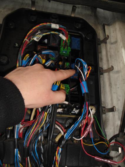
2 This module can be connected anywhere in the vehicle near the SCR CAN data cables and power supply cables, positive and negatives wires will also be required. These wires can be located in the cabin s fuse box. Top row, green connector. The NOX sensor ant the SCR ECU has its own specifically codes for each vehicle. The testing module is equipped with a coding function and has to be adapted to every vehicle individually. Adapting the testing module These testing modules are equipped with an automatic adaptation function. Although MAXI models have an additional coding device, which is crucial when diagnosing serious malfunctions, such as complete failure of the NOX sensor and/or the SCR ECU. Carrying out the automatic adaptation In order to carry out the automatic adaptation you must connect the following wires: red, brown, yellow, blue. You must connect all those wires only then, when the ignition is off. The automatic adaptation function will start when the green wire (which determines the modules function) you will connect to the vehicles positive cable. When you will connect everything according this manual, switch the ignition on. Do not disconnect the NOX sensor and the SCR ECU! You can watch over the adaptation process using the bi-coloured LED indicator, which is located on the module. Step 1: Red indicator light is on for about 2 onds. This is handshaking time to engage various processes in the vehicle and in the module. Step 2: Indicator light flashes continuously with 0.2. intervals. NOX sensor and SCR ECU initialization has begun. This lasts for about 3-4 onds. If this continues for 10-20, either this indicates a complete failure of the NOX sensor and/or the SCR ECU, or an unforeseen problem occurred. To ensure that no errors occurred while connecting the wires, the connections have to checked or redone. If the outcome is the same then you should contact a consultant. Step 3: The indicator light flashes green continuously with 0.2 intervals. This indicates a successful NOX sensor and SCR ECU initialization. Data transfer will start it lasts up to 30. If it last longer than 1-2 minutes, either this means a complete failure of the NOX sensor and/or the SCR ECU, or an unforeseen problem occurred. To ensure that no errors occurred while connecting the wires, the connections have to checked or redone. If the outcome is the same then you should contact a consultant. Step 4: A green LED light indicates a successful coding procedure. Switch the ignition off, disconnect the green wire form the positive wire, and connect it to the negative. This means that you switch the module from adaptation mode to working mode. NOTE! Never leave the green wire disconnected. The device will still work, but due to some circumstances, it might become unstable. You must connect the green wire at all times either to the positive or to the negative wire, depending on the selected mode. During the adaptation to the positive cable, during normal working mode to the negative cable. Step 5: When you will connect the green wire to the negative cable, the device automatically will switch into normal working mode. The device indicates working mode by the LED light, which flashes green every ond. Green light indicates that the module has been successfully coded and in working mode. If the LED flashes red light with 1. intervals this indicates that the coding
3 was, either not successful or not carried out at all. This means that you must repeat everything from step 1. Step 6: Now you can carry out maintenance work and various tests; the initialization of the testing module is complete. You can also disconnect the NOX sensor and/or the SCR ECU by simply disconnecting fuses no.6 and no. 357 from the fuse block. Note: do not leave the testing module and the original components connected for a long time. Flashing interval Colour Description Result Constantly on Red Lights up for <2. after Normal function. switching the ignition on. Various processes engaged. Red Testing module and vehicle s initialization processes is on before <10. normal; >30. repeat the adaptation. everything from step 1 Green Data transfer is in progress <30. normal >2 min repeat everything from step 1 Constantly on Green Adaptation complete Disconnect the green wire from the positive lead and connect it to the negative lead. Flashes for 1 Red Device is in working mode. Adaptation process not carried out or carried out not fully. Repeat everything from step 1 Flashes for 1 Green Device in working mode, Normal process adaptation complete Red/green No communication with CAN Check connections

4


5 Setup no.1 Setup no.2
Volvo SCR testing module
 Volvo SCR testing module Brief module description We design this module to test the Volvo SCR system (subsequently SCR) and its components. Using this module, you can test different SCR components, such
AddBlueOff Auto Pass V2. Installation guide. AUTO Pass. by ADDBlueOFF.net. Version 2
 Installation guide AUTO Pass by ADDBlueOFF.net Version 2 1 Contents Module description...... 2 MAN install recommendation... 8 Modules Inputs / Outputs.... 2 Pin assignments.... 3 Module modes..... 3 Module
The installation instructions for an intake manifold flap control motor (Inlet Port Shut Off Valve) testing device of Mercedes Benz OM642 engine
 testing device of Mercedes Benz OM642 engine") The installation instructions for an intake manifold flap control motor (Inlet Port Shut Off Valve) testing device of Mercedes Benz OM642 engine 1. A brief description of the testing device. The testing
The installation instructions for an intake manifold flap control motor (Inlet Port Shut Off Valve) testing device of Mercedes Benz OM642 engine 1. A brief description of the testing device. The testing
UNISTEER Performance Products UNIVERSAL HOT ROD ELECTRA-STEER KIT
 UNISTEER Performance Products UNIVERSAL HOT ROD ELECTRA-STEER KIT 8051500 BEFORE YOU START PLEASE READ! Designing steering systems requires an understanding of steering function and design. If you are
Preparing and programming of ESGI 2 LPG supply system manual
 Preparing and programming of ESGI 2 LPG supply system manual Part II Instruction of preparing and programming the ESGI system 1 Technical data of the central unit Vs Power supply voltage 0...16V V i_an
12 Volt 1500 Amp Intelli-Start LITHIUM JUMPSTARTER
 12 Volt 1500 Amp Intelli-Start LITHIUM JUMPSTARTER P/No. IS1500 IMPORTANT SAFETY INFORMATION Please read this manual thoroughly before use and store in a safe place for future reference. WARNINGS Do not
DIGITAL GEAR INDICATOR
 DIGITAL GEAR INDICATOR USER GUIDE AND INSTRUCTIONS JULY 2016 CONTENTS INTRODUCTION PAGE 1 INSTALLATION PAGE 2 ENTER MODE PAGE 3 SHIFT LIGHTS - SET LOWER RPM PAGE 4 SHIFT LIGHTS - SET HIGHER RPM PAGE 5
SEAS - INSTRUCTIONS - MERCEDES -
 SEAS - INSTRUCTIONS - MERCEDES - Please read the complete document before starting the installation Brand assignment SEAS add-on module is delivered NOT PROGRAMMED, therefore a brand (Mercedes in this
Emulator AUTOPASS V2
 Emulator AUTOPASS V2 Installation guide Module description The CAN bus interface module (Emulator) Auto Pass V2, (referred to as Module in these instruction) is used to simulate a fully working exhaust
Operating Manual OBD Link Connector
 Operating Manual OBD Link Connector OBD Link Connector (OLC) provides the following functions when it is plugged into the car or truck Diagnostic Link Connector (DLC) port: 1. TEST OBD2 PORT BEFORE PLUG
Fault Code 34 - Weak Battery Voltage Supply
 Fault Code 34 - Weak Battery Voltage Supply Fault Isolation Procedures TRTS0930 Fault Code 34 - Weak Battery Voltage Supply J1587: MID 130 PID 168 FMI 14 J1939: SA 3 SPN 168 FMI 14 Overview This fault
CAPACITOR ACTUATED PORTABLE STARTER CAPS USER GUIDE. INST048 Doc 3.01
 CAPACITOR ACTUATED PORTABLE STARTER CAPS USER GUIDE INST048 Doc 3.01 CONTENTS General Information...2 Charts...3 Before First Use...4 Safety Requirements...5 What to Expect from the CAPS...5 CAPS Diagram...6
User s Manual. Automatic Switch-Mode Battery Charger
 User s Manual Automatic Switch-Mode Battery Charger IMPORTANT Read, understand, and follow these safety rules and operating instructions before using this battery charger. Only authorized and trained service
English. Fitting Instructions: Trophy and Trophy SE A of 12. Parts Supplied:
 English Fitting Instructions: Trophy and Trophy SE A9808015 Thank you for choosing this Triumph genuine accessory kit. This accessory kit is the product of Triumph's use of proven engineering, exhaustive
Fitting Instructions: Street Triple from VIN and Street Triple R from VIN A
 English Fitting Instructions: Street Triple from VIN 560477 and Street Triple R from VIN 560477 A9808113 Thank you for choosing this Triumph genuine accessory kit. This accessory kit is the product of
Installation and Operation Guide
 Bus-Scan 500 RF Installation and Operation Guide All Content and Information are Copyright 2018-2019 Robotics Technologies, Inc. Features and Information are subject to change without notice. All Rights
NOTES: 1489 N THESTA FRESNO, CA PHONE (559) FAX (559)
 FAX (559)") NOTES: 1489 N THESTA FRESNO, CA. 93703 PHONE (559)486-5444 FAX (559)486-5155 Contents: REMOTE X 2 THIS IS ONLY A GUIDE!!! BUTTON X 16 THE APPLICATIONS SHOWN ARE GENERAL GUIDE LINES OF POSSIBLE APPLICATIONS.
NOTES: 1489 N THESTA FRESNO, CA. 93703 PHONE (559)486-5444 FAX (559)486-5155 Contents: REMOTE X 2 THIS IS ONLY A GUIDE!!! BUTTON X 16 THE APPLICATIONS SHOWN ARE GENERAL GUIDE LINES OF POSSIBLE APPLICATIONS.
Introduction. Drenth Motorsport Gearboxes Fleuweweg AG Enter The Netherlands Phone: +31 (0) Fax: +31 (0)
 Fax: +31 (0)") 25.03.0023 Introduction The display unit comes with a software application. With the software application information shown on the display can be adjusted. There are different modes to adjust: the shape
25.03.0023 Introduction The display unit comes with a software application. With the software application information shown on the display can be adjusted. There are different modes to adjust: the shape
Installation Tips for your RS-1 + Honda-SL3 (1.b) Remote starter Honda: ( FIT), ( Pilot), ( Ridgeline) Acura: ( MDX)
 Remote starter Honda: ( FIT), ( Pilot), ( Ridgeline) Acura: ( MDX)") Installation Tips for your RS-1 + Honda-SL3 (1.b) Remote starter Honda: ( 06-08 FIT), ( 05-08 Pilot), ( 06-13 Ridgeline) Acura: ( 03-06 MDX) TIP SHEET T0777 Thank you for purchasing your remote start from
Installation Tips for your RS-1 + Honda-SL3 (1.b) Remote starter Honda: ( 06-08 FIT), ( 05-08 Pilot), ( 06-13 Ridgeline) Acura: ( 03-06 MDX) TIP SHEET T0777 Thank you for purchasing your remote start from
Installation and Operation Guide
 Bus-Scan CR2 RF Installation and Operation Guide All Content and Information are Copyright 2018 Robotics Technologies, Inc. Features and Information are subject to change without notice. All Rights Reserved.
THREE PHASE RECHARGING SYSTEM DIAGNOSIS
 THREE PHASE RECHARGING SYSTEM DIAGNOSIS INDEX 1. Foreword 2. Battery Voltage 3. Recharging System Connections 4. Stator Three Phase Continuity 5. Alternator Phase Insulation 6. Checking Absorption with
MODULE TEST UNIT. Part No: MTU-12 V2.1
 MODULE TEST UNIT Part No: MTU-12 WHITE YEL ORANGE VEHICLE RED 150 Fused + 12 Volt BLACK 150 RED + 12 Volt Out BLACK Out WHITE Pulse ( adjustable by pot) Left High LED will light over 4.5 V Left Low LED
BE 1 BODY ELECTRICAL SYSTEM
 BE1 BE2 GENERAL INFORMATION Wiring color code Wire colors are indicated by an alphabetical code. B = Black L = Blue R = Red BR = Brown LG = Light Green V = Violet G = Green O = Orange W = White GR = Gray
Service Bulletin Trucks
 Volvo Trucks North America, Inc. Greensboro, NC USA Service Bulletin Trucks Date Group No. Page 9.2003 300 004 1(10) General Safety Practices Electrical and Electronics VN, VHD General Safety Practices
CANBUS Translator. Overview - Installation and Operating Instructions
 CANBUS Translator Overview - Installation and Operating Instructions Contents Overview... 1 Installation... 3 Basic Install... 3 GM to Subaru BRZ/Toyota 86 Install... 4 Subaru Legacy Gen4/Gen3 Impreza
CHECKLIST & COMPONENTS
 Eclipse Compact www.rollershuttercompany.com Tel 0800 6444121 55mm Roller Garage Doors CHECKLIST & COMPONENTS EQUIPMENT REQUIRED 2 x Step ladders or hop ups Spirit level Tape measure Power drill 10mm A/F
PLATINUM SERIES. Haltech. High Power Igniter Module QUICK START GUIDE. 4 Channel - # HT Channel - # HT Channel - # HT020040
 PLATINUM SERIES Haltech High Power Igniter Module QUICK START GUIDE 4 Channel - # HT020032 6 Channel - # HT020036 8 Channel - # HT020040 HALTECH HEAD OFFICE: PH: +612 9729 0999 FAX: +612 9729 0900 EMAIL:
MAKE OF AUTOMOBILE: TYPE: V 70 PISTON DISPLACEMENT: 2521 NUMBER OF VALVES:
 MAKE OF AUTOMOBILE: TYPE: V 70 PISTON DISPLACEMENT: 2521 NUMBER OF VALVES: 20V ENGINE NUMBER: B5254T TRANSMISSION TYPE ( MT / AT ) AT VEHICLE CATEGORIES M or N PASSENGER CAR ( M ) TYPE VSI INJECTOR (COLOUR
UNIVERSAL ELECTRA-STEER FOR 2 COLUMN 220w Plain w Polished w Plain w Polished
 UNIVERSAL ELECTRA-STEER FOR 2 COLUMN 220w Plain 8052810 220w Polished 8052610 360w Plain 8052780 360w Polished 8052760 Full refund will NOT be granted to any kits that are damaged, scratched, or altered
Installation Guide Rollerdor RD55 Econ Roller Garage Door
 Installation Guide Rollerdor RD55 Econ Roller Garage Door 1 Finished door Rollerdor RD55 Econ Roller Garage Door CHECKLIST & COMPONENTS EQUIPMENT REQUIRED 2 x Step ladders or hop ups Spirit level Tape
1999 Toyota RAV ACCESSORIES & EQUIPMENT Cruise Control Systems - RAV4
 1999 ACCESSORIES & EQUIPMENT Cruise Control Systems - RAV4 DESCRIPTION WARNING: Deactivate air bag system before performing any service operation. See AIR BAG RESTRAINT SYSTEMS article. DO NOT apply electrical
INSTALLATION MANUAL STEP SLIDER BD-SS-200-JK4. Made in the USA. Front Bracket Middle Bracket Rear Bracket. Tools Required
 Made in the USA INSTALLATION MANUAL STEP SLIDER BD-SS-200-JK4 Description Quantity Electric Step Slider (Pair) 2 Front Bracket Middle Bracket Rear Bracket Bump stop plate with VHB backing 2 Wiring harness
Headlight Removal & Installation: VW Jetta Mk.4 / Bora
 Headlight Removal & Installation: 99-04 VW Jetta Mk.4 / Bora Disclaimer: Buyer assumes any and all risk and liability from the installation and use of this product. Seller, author, or any of their affiliates
MODEL YEAR: 2009 SYSTEM APPROVAL NUMBER ( R115 ) R ENGINE SET NUMBER 350/
 R ENGINE SET NUMBER 350/") MAKE OF AUTOMOBILE: TYPE: PRIORA 2170 / 2172 PISTON DISPLACEMENT: 1600 NUMBER OF VALVES: 16 ENGINE NUMBER: 21126 TRANSMISSION TYPE ( MT / AT ) MT VEHICLE CATEGORIES M or N M TYPE VSI INJECTOR (COLOR )
MAKE OF AUTOMOBILE: TYPE: PRIORA 2170 / 2172 PISTON DISPLACEMENT: 1600 NUMBER OF VALVES: 16 ENGINE NUMBER: 21126 TRANSMISSION TYPE ( MT / AT ) MT VEHICLE CATEGORIES M or N M TYPE VSI INJECTOR (COLOR )
TIP SHEET. Installation Tips for your RS IB-MUX / PKUMUX (D) + SPDT T1205 v1.2 4/3/14. 1 P a g e
 + SPDT T1205 v1.2 4/3/14. 1 P a g e") Installation Tips for your RS-150 + IB-MUX / PKUMUX (D) + SPDT T1205 v1.2 4/3/14 TIP SHEET Thank you for purchasing your remote start from MyPushcart.com - an industry leader in providing remote starts
Installation Tips for your RS-150 + IB-MUX / PKUMUX (D) + SPDT T1205 v1.2 4/3/14 TIP SHEET Thank you for purchasing your remote start from MyPushcart.com - an industry leader in providing remote starts
Cruise Control designed. The only. and developed in Australia CRUISE CONTROL OPERATING INSTRUCTIONS. PROFESSIONAL SERIES and DRIVE by WIRE
 The only Cruise Control designed and developed in Australia CRUISE CONTROL OPERATING INSTRUCTIONS PROFESSIONAL SERIES and DRIVE by WIRE CONGRATULATIONS! You have purchased one of the most advanced cruise
Instruction Manual. Instruction Manual LIFETIME PLU Manufactured and packaged for SRGS PTY LTD ABN CONDITIONAL
 12V 3300mAh MINI JUMP START 12V 3300mAh MINI JUMP START Instruction Manual Instruction Manual LIFETIME Manufactured and packaged for SRGS PTY LTD ABN 23 113 230 050 751and Gympie Road, Queensland 4501,
Gobius 1, Level Switch for Water, Fuel and Fluid Tanks, new version 5.0. Installation Guide. Before you begin
 Document release, 5.12, July 2017 Gobius 1, Level Switch for Water, Fuel and Fluid Tanks, new version 5.0 Installation Guide Before you begin 1. Please make sure that no part is missing. 1 sensor, 1 panel,
XIAOMI-MI.COM. Xiaomi Yunbike C 1. Accessories XIAOMI-MI.COM. Battery Charging device Pedals х 2 Hex wrench Keys х 2 Wrench
 Xiaomi Yunbike C 1 Accessories Battery Charging device Pedals х 2 Hex wrench Keys х 2 Wrench 1. Wheel 2. Front sleeve 3. Fork 4. Front brake 5. Brake System 6. Headlights 7. Front steering cup 8. Wheel
TV-Free TF-NTG5. compatible with Mercedes Benz Comand Online NTG5 / NTG5.1 navigation systems
 TV-Free Video-in-motion Interface compatible with Mercedes Benz Comand Online NTG5 / NTG5.1 navigation systems Legal Information By law, watching moving pictures while driving is prohibited, the driver
TV-Free TF-LR. compatible with Land Rover touch-screen navigation systems
 TV-Free Video-in-motion Interface compatible with Land Rover touch-screen navigation systems Legal Information By law, watching moving pictures while driving is prohibited, the driver must not be distracted.
Congratulations. You ve just purchased the most advanced flasher available on the market today. This
 Congratulations. You ve just purchased the most advanced flasher available on the market today. This relay-isolated, solid-state module is designed to be installed into vehicles with a positive switched
Quick-Kill Installation Manual V1.0 (Universal Motorcycle Application)
") Quick-Kill Installation Manual V1.0 (Universal Motorcycle Application) THIS INSTALLATION MANUAL IS FOR UNIVERSAL FUEL INJECTED MOTORCYCLE APPLICATIONS (NON PLUG AND PLAY), WITH OR WITHOUT A GEAR POSITION
Quick-Kill Installation Manual V1.0 (Universal Motorcycle Application) THIS INSTALLATION MANUAL IS FOR UNIVERSAL FUEL INJECTED MOTORCYCLE APPLICATIONS (NON PLUG AND PLAY), WITH OR WITHOUT A GEAR POSITION
Function description
 Function description The Display unit, which Drenth can supply, has the following options: Gearindication: The gear indicator displays the selected gear by measuring the position of the selector barrel
INSTALL GUIDE FLCI-IDS(RS)-BZ4-[FLRSBZ4]-EN
![INSTALL GUIDE FLCI-IDS(RS)-BZ4-[FLRSBZ4]-EN](/thumbs/95/126494956.jpg "INSTALL GUIDE FLCI-IDS(RS)-BZ4-[FLRSBZ4]-EN") INSTALL GUIDE DOCUMENT NUMBER 58247 REVISION DATE 20190116 FIRMWARE FLCI-IDS(RS)-BZ4-[FLRSBZ4] HARDWARE FLRSBZ4 ACCESSORIES FLPROG (REQUIRED) FLRF1/2/4 (OPTIONAL) MYCAR (OPTIONAL) TERMS OF USE: Automotive
INSTALL GUIDE DOCUMENT NUMBER 58247 REVISION DATE 20190116 FIRMWARE FLCI-IDS(RS)-BZ4-[FLRSBZ4] HARDWARE FLRSBZ4 ACCESSORIES FLPROG (REQUIRED) FLRF1/2/4 (OPTIONAL) MYCAR (OPTIONAL) TERMS OF USE: Automotive
AUTOMATIC LEVELING SYSTEM OPERATION & MAINTENANCE
 WARNING For maximum stability during use of the PowerPlus Leveling Systems, all levelers and wheels must be in contact with the ground. NEVER use levelers to change tires or to perform under chassis work
User Manual WT Combi-S Pure Sinus Wave Inverter
 User Manual WT Combi-S Pure Sinus Wave Inverter Contents 1. Important Safety information 1.1. Safety Information part 1 1.2. Safety information part 2 2. General Features 2.1. Product overview 3. Connection
12/24 Volt Trailer, Caravan Electrical Tow Plug And Light Tester Basic
 12/24 Volt Trailer, Caravan Electrical Tow Plug And Light Tester Basic User Manual 1 12/24 Volt Trailer, Caravan Electrical Tow Plug And Light Tester INDEX 12/24 Volt Trailer, Caravan Electrical Tow Plug
Gobius 4 for Waste Holding Tanks, new version 5.0
 Document release 5.12, July 2017 Gobius 4 for Waste Holding Tanks, new version 5.0 Installation Guide Before you begin 1. Please make sure that no part is missing. 3 sensors, 1 panel, 1 control unit, 1
REPAIR MANUAL ZT2452A
 REPAIR MANUAL ZT2452A Swisher Mower Co Warrensburg, MO Table of Contents Belt Routing.. 4 Wiring Diagram.. 4 Diagnosing Starting Problems..... 5 Diagnosing PTO Clutch Problems....6 Engine Running in Normal
Allows 2 relays to be activated. based on RPM and throttle. This guide will give you a general overview to the use of the HUB
 Options Pressure input Map Switch Output Gear/Speed Input Allows the map to be trimmed Allows the user to change Allows 2 relays to be activated Allows the map to be trimmed based on pressure/boost input
BODY ELECTRICAL SYSTEM
 BODY ELECTRICAL SYSTEM 8-1 SECTION 8 BODY ELECTRICAL SYSTEM WARNING: For vehicles equipped with Supplemental Restraint (Air Bag) System: Service on and around the air bag system components or wiring must
O2 Sensor Testing. If your engine has unexpectedly started to run poorly, an O2 Sensor Test should be performed.
 O2 Sensor Testing If your engine has unexpectedly started to run poorly, an O2 Sensor Test should be performed. IMPORTANT: Testing the O2 sensors using the procedures below REQUIRES that the engine will
APOLLO Model # - F-12013, F-22013, D-50115, D-50215, D-50415, D-50615, D-50815, D Apollo Series- Instruction Manual V.3
 Apollo Series- Instruction Manual V.3 APOLLO Model # - F-12013, F-22013, D-50115, D-50215, D-50415, D-50615, D-50815, D-51015 This instruction manual serves as a guide for the Apollo Series. IMPORTANT!
DL 38 DOOR LOCK WIRELESS DOOR LOCK CONTROL SYSTEM REGISTRATION
 38 DOOR WIRELESS DOOR CTROL SYSTEM REGISTRATI 1. REGISTER RECOGNITI CODES Recognition code registration is necessary when the door control transmitter or the door control receiver is replaced with a new
ROCKLEA TRUCK ELECTRICAL. Sleeper Air NXT. Owner s Manual. Revision th March 2013
 ROCKLEA TRUCK ELECTRICAL Sleeper Air NT Owner s Manual Revision 230 24 th March 2013 Rocklea Truck Electrical Rocklea Truck Electrical is Brisbane's premier truck lighting and custom accessory manufacturer
Please Read this manual before operating your UltraRide Suspension, and keep it for future reference.
 OWNER S MANUAL Model # 800M1300 Lot/Serial # Questions? Contact this Professional Installer : Company : Phone : ELECTRONIC AIR CONTROL KIT Installer : Date : MN-769 80003011 MAR 20, 2013 Please Read this
Installation and Users Guide. Plain-Talk. MINI Bluetooth kit with Steering Wheel Controls. Version 2.1
 Installation and Users Guide MINI Bluetooth kit with Steering Wheel Controls Version 2.1 Plain-Talk This product covers all Mini Cooper vehicles as follows: 03/2002-2006 Model Year Mini Cooper and Cooper
ARC4000e 4 wheel compressor system w / 4 way Ride Pro controller
 350 S. St. Charles St. Jasper, In. 47546 Ph. 812.482.2932 Fax 812.634.6632 on the internet: www.ridetech.com ARC4000e 4 wheel compressor system w / 4 way Ride Pro controller 1 ARC5001 Compressor 1 CON6000
Power Inverter 400 MW Owner s Manual
 Power Inverter 400 MW 1204 Owner s Manual For safe and optimum performance, the Power Inverter must be used properly. Carefully read and follow all instructions and guidelines in this manual and give special
Installation Instructions
 This product has been designed and manufactured to work correctly with installation as described in these instructions. Failure to follow these instructions could result in damage to property, damage to
LPG STARTBOX. Instruction Manual. Rempel Power Systems GmbH
 LPG STARTBOX Rempel Power Systems GmbH 2014-10-24 Content Installation Guidelines... 2 Layout... 2 Getting started (Learning mode)... 3 Operating mode... 5 Switch positions... 6 Programming mode (Firmware
CLIFFORD CONCEPT 300 Wiring Instructions Re-compiled and illustrated by Ray Heffer (www.rayheffer.com)
") CLIFFORD CONCEPT 300 Wiring Instructions Re-compiled and illustrated by Ray Heffer (www.rayheffer.com) Wiring Description for the 9-Pin Connector Pin Label Connects to Inputs Outputs 1 Ground (-) Ground
CLIFFORD CONCEPT 300 Wiring Instructions Re-compiled and illustrated by Ray Heffer (www.rayheffer.com) Wiring Description for the 9-Pin Connector Pin Label Connects to Inputs Outputs 1 Ground (-) Ground
Nissan GTR Alpha Fuel System
 Nissan GTR Alpha Fuel System Instructions V5 The goal of AMS is to provide the highest quality, best performing products available. By utilizing research and development, and rigorous testing programs
INSTALLATION GUIDE Six Gauge Universal Digital Dash Panel Part Number: DP10002
 Made in America Lifetime Guarantee Thank you for purchasing this digital dash panel from Intellitronix. We value our customers! INSTALLATION GUIDE Six Gauge Universal Digital Dash Panel Part Number: DP10002
MAKE OF AUTOMOBILE: MODEL YEAR: 2007 SYSTEM APPROVAL NUMBER ( R115 ) VSI-LPG 10 ENGINE SET NUMBER 364/
 VSI-LPG 10 ENGINE SET NUMBER 364/") MAKE OF AUTOMOBILE: TYPE: FABIA PISTON DISPLACEMENT: 1400 NUMBER OF VALVES: 16 ENGINE NUMBER: BUD TRANSMISSION TYPE ( MT / AT ) MT VEHICLE CATEGORIES M or N M TYPE VSI INJECTOR ( NUMBER + COLOR ) 180/30410
MAKE OF AUTOMOBILE: TYPE: FABIA PISTON DISPLACEMENT: 1400 NUMBER OF VALVES: 16 ENGINE NUMBER: BUD TRANSMISSION TYPE ( MT / AT ) MT VEHICLE CATEGORIES M or N M TYPE VSI INJECTOR ( NUMBER + COLOR ) 180/30410
English. Fitting Instructions: Thunderbird Commander and Thunderbird LT A of 7. Parts Supplied:
 English Fitting Instructions: Thunderbird Commander and Thunderbird LT A968089 Thank you for choosing this Triumph genuine accessory kit. This accessory kit is the product of Triumph's use of proven engineering,
SE AS - INSTRUCTIONS - Volvo -
 SE AS - INSTRUCTIONS - Volvo - Please read the complete document before starting the installation Brand assignment SEAS add-on module is delivered NOT PROGRAMMED, therefore a brand (Volvo in this case)
Installation instruction BMW E36 Convertible remote roof module
 Installation instruction BMW E36 Convertible remote roof module Before the Installation: Please read this guide carefully and take your time with the installation. Incorrect installation of this module
Livewire TS User Guide
 Livewire TS User Guide Introduction: - This guide will provide a brief overview of how to use the Livewire TS device. Please be sure you have the Livewire TS with the vehicle before continuing. Loading
Installation Tips - (Crimestopper RS1/RS2) & (Fortin EVO-ALL 5): *regular key & automatic transmission only*
 & (Fortin EVO-ALL 5): *regular key & automatic transmission only*") Installation Tips - (Crimestopper RS1/RS2) & (Fortin EVO-ALL 5): TIP SHEET T3385f, T3413f *regular key & automatic transmission only* Thank you for purchasing your remote start from MyPushcart.com - an
Installation Tips - (Crimestopper RS1/RS2) & (Fortin EVO-ALL 5): TIP SHEET T3385f, T3413f *regular key & automatic transmission only* Thank you for purchasing your remote start from MyPushcart.com - an
LED Flasher. R1 R2 100 F + C1 100 F +
 LED Flasher. Specification Operates from a 6-12V supply. Alternately flashes two LEDs. Flash rate adjustable by changing the capacitor values and the 10k resistor values. Circuit Diagram 9V LED1 470 TR1
THE JING ORB. Augmented Therapy System for Rapid Recovery. user manual
 THE JING ORB Augmented Therapy System for Rapid Recovery user manual New and Improved This ORB contains our new and greatly improved centerpiece which provides a 50% increase in the field produced. Unlike
RS4-7/PS4-7 + (2) + SPDT T3015, T3053
 + SPDT T3015, T3053") TIP SHEET Installation Tips for your RS4-7/PS4-7 + Honda-SL3 (2) + SPDT T3015, T3053 v1.3 4/25/14 Honda: ( 98-02 Accord), ( 98-01 CRV), ( 98-04 Odyssey), ( 03-04 Pilot) Acura: ( 98-99 EL), ( 98-03 CL),
TIP SHEET Installation Tips for your RS4-7/PS4-7 + Honda-SL3 (2) + SPDT T3015, T3053 v1.3 4/25/14 Honda: ( 98-02 Accord), ( 98-01 CRV), ( 98-04 Odyssey), ( 03-04 Pilot) Acura: ( 98-99 EL), ( 98-03 CL),
RAD Sportz Electric Air Pump & Gauge INSTRUCTION MANUAL
 RAD Sportz Electric Air Pump & Gauge INSTRUCTION MANUAL R A D S P O R T Z 1 2 V O L T A I R P U M P Durable Steel Components Ultimate in Portability; Keep in Trunk RV, Camper 3 Adapters: Use for Autos,
TIP SHEET T2352, T3396. Installation Tips for RS1 + EVO-ALL 1-BUTTON REMOTE STARTER FOR: Acura RDX PUSH-TO-START / AUTOMATIC
 Installation Tips for RS1 + EVO-ALL 1-BUTTON REMOTE STARTER FOR: Acura RDX 2013-2015 PUSH-TO-START / AUTOMATIC TIP SHEET T2352, T3396 Thank you for purchasing your remote start from MyPushcart.com - an
In-Tank Fuel Pump. Technical Spec ECOTRONS LLC COPY RIGHTS ECOTRONS ALL RIGHTS RESERVED
 In-Tank Fuel Pump Technical Spec ECOTRONS LLC COPY RIGHTS ECOTRONS ALL RIGHTS RESERVED Note: If you have problems or need more detail, please contact us at info@ecotrons.com. Product: Part#: Comment: In-Tank
Automotive Data Solutions Inc. AVAILABLE FOR : ADS-BLADE AL. Rev. Date: December 27, 2017 Doc. No.: ##46762##
 Automotive Data Solutions Inc. INSTALL GUIDE BLADE-AL(DL)-HA2-EN AVAILABLE FOR : ADS-BLADE AL Rev. Date: December 27, 2017 Doc. No.: ##46762## HA2 U.S. PATENT NO. 8,856,780 PLEASE VISIT WWW.IDATALINK.COM
Wiring Main Power connector constant 12V power
 DHC-2000 Digital Height Control System Introduction This control system can be connected to a display module and height sensors or pressure senders to allow monitoring and control of all four corners and
SUPPLEMENTAL RESTRAINT SYSTEM (SRS)
") GROUP 52B SUPPLEMENTAL RESTRAINT SYSTEM (SRS) CONTENTS GENERAL INFORMATION........ 52B-3 SERVICE PRES......... 52B-5 SPECIAL TOOLS................ 52B-8 TEST EQUIPMENTS............. 52B-9............ 52B-10
GROUP 52B SUPPLEMENTAL RESTRAINT SYSTEM (SRS) CONTENTS GENERAL INFORMATION........ 52B-3 SERVICE PRES......... 52B-5 SPECIAL TOOLS................ 52B-8 TEST EQUIPMENTS............. 52B-9............ 52B-10
Installation Tips for your Crimestopper/ProStart Remote Start system (add-on for GM vehicles) v1.02 updated 1/16/2013
 v1.02 updated 1/16/2013") Installation Tips for your Crimestopper/ProStart Remote Start system (add-on for GM vehicles) v1.02 updated 1/16/2013 Thank you for purchasing your remote start from MyPushcart.com - an industry leader
Installation Tips for your Crimestopper/ProStart Remote Start system (add-on for GM vehicles) v1.02 updated 1/16/2013 Thank you for purchasing your remote start from MyPushcart.com - an industry leader
UNIVERSAL GAUGE WIRE HARNESS
 2650-1797-00 UNIVERSAL GAUGE WIRE HARNESS For Installing Auto Meter Electric Speedometer, Tachometer, And Short Sweep Electric Oil Pressure, Water Temperature, Fuel Level, and Volt Meter Gauges. This harness
ATD-5598 Self-Powered Inductive Clamp Timing Light
 ATD-5598 Self-Powered Inductive Clamp Timing Light The original battery powered timing light, built with quality to last. There's no need to connect to a 12V battery for power. Unit is powered by (2) D
Installation Guide. RunLock
 Installation Guide RunLock Seat Leon III (2012-), Ateca (2016-) Skoda Fabia III (2014-), Octavia III (2012-), Superb (2015-) VW Touran (2015-), Tiguan (II. Gen; 2016-), Golf VII (2012-), Golf Sportsvan
Smile 11 RA/-B Smile 12 RF/-G Reset button
 Original Instructions Smile 11 RA/-B Smile 12 RF/-G Reset button ABB Jokab Safety Varlabergsvägen 11, SE-434 39 Kungsbacka, Sweden www.abb.com/jokabsafety Read and understand this User Manual Please read
SRS AIRBAG CONTROL SYSTEM
 RESTRAINTS SECTION SRC A SRS AIRBAG CONTROL SYSTEM B C D CONTENTS E BASIC INSPECTION... 3 DIAGNOSIS AND REPAIR WORK FLOW... 3 Work Flow...3 INTERMITTENT INCIDENT... 5 Inspection Procedure...5 Trouble Diagnosis
CRUISE CONTROL SPEED LIMITER Rev. 4.0
 INSTALLATION f MANUAL CRUISE CONTROL & SPEED LIMITER AP900Series SL900Series 231.0004530 Rev. 4.0 1 2 CONTENTS: Chapters 1 Kit contents. 3 2 Tools required 4 3 Electronics module location... 5 4 Input
240V UPS Typical Installation Guide
 240V UPS Typical Installation Guide Warning!!! High Battery DC Voltages can Cause Serious Injury or Death. Installation should only be done by suitable qualified personal. Aug, 2016 1 www.balancell.com
Ground Control TT Leveling System OWNER'S MANUAL
 Ground Control TT Leveling System OWNER'S MNUL TBLE OF CONTENTS System Information 2 Features 2 Safety Information 2 Touch Pad Diagram 3 Operation 4 Basic Jack Operation 4 Unhitching From Tow Vehicle 4
U S A 1 WAY. User's Guide E P
 1 WAY User's Guide E P 400 www.easycar-usa.com We Promise to offer you the highest quality products. We sincerely appreciate you purchasing our Push Button Start System. Our Push Button Start System is
MAKE OF AUTOMOBILE: PISTON DISPLACEMENT: 1300
 MAKE OF AUTOMOBILE: TYPE: YARIS PISTON DISPLACEMENT: 1300 NUMBER OF VALVES: 16 VVT-I ENGINE NUMBER: 2SZ-FE TRANSMISSION TYPE ( MT / AT ) AT VEHICLE CATEGORIES M or N M TYPE VSI INJECTOR ( NUMBER + COLOR
MAKE OF AUTOMOBILE: PISTON DISPLACEMENT: 8300 NUMBER OF VALVES: 20 TRANSMISSION TYPE ( MT / AT ) TYPE VSI INJECTOR (COLOR ) VERSION ( LPG / CNG )
 TYPE VSI INJECTOR (COLOR ) VERSION ( LPG / CNG )") MAKE OF AUTOMOBILE: TYPE: PISTON DISPLACEMENT: 8300 NUMBER OF VALVES: 20 ENGINE NUMBER: SRT V10 Viper TRANSMISSION TYPE ( MT / AT ) AT TYPE VSI INJECTOR (COLOR ) YELLOW VERSION ( LPG / CNG ) LPG INJECTION
MAKE OF AUTOMOBILE: TYPE: PISTON DISPLACEMENT: 8300 NUMBER OF VALVES: 20 ENGINE NUMBER: SRT V10 Viper TRANSMISSION TYPE ( MT / AT ) AT TYPE VSI INJECTOR (COLOR ) YELLOW VERSION ( LPG / CNG ) LPG INJECTION
MAKE OF AUTOMOBILE: 316 / 318i E46 NUMBER OF VALVES:
 MAKE OF AUTOMOBILE: TYPE: 316 / 318i E46 PISTON DISPLACEMENT: 1800 2000 cc NUMBER OF VALVES: 16V ENGINE NUMBER: N42B18A / N42B20A TRANSMISSION TYPE ( MT / AT ) MT VEHICLE CATEGORIES M or N M TYPE VSI INJECTOR
Kwikee IMGL Step Control Testing Procedure #82-ST0500
 Kwikee IMGL Step Control Testing Procedure #82-ST0500 TABLE OF CONTENTS Introduction 2 Resources Required 2 General Service Notes 3 Preparation 5 Troubleshooting and Test Procedures 5 Testing the Step
MODEL YEAR: SYSTEM APPROVAL NUMBER ( R115 ) R ENGINE SET NUMBER 354/
 R ENGINE SET NUMBER 354/") MAKE OF AUTOMOBILE: MERECEDES TYPE: E200 W211 PISTON DISPLACEMENT: 1796 NUMBER OF VALVES: 16 ENGINE NUMBER: M271 TRANSMISSION TYPE ( MT / AT ) AT VEHICLE CATEGORIES M or N M TYPE VSI INJECTOR ( NUMBER
MAKE OF AUTOMOBILE: MERECEDES TYPE: E200 W211 PISTON DISPLACEMENT: 1796 NUMBER OF VALVES: 16 ENGINE NUMBER: M271 TRANSMISSION TYPE ( MT / AT ) AT VEHICLE CATEGORIES M or N M TYPE VSI INJECTOR ( NUMBER
1968 PLYMOUTH ROAD RUNNER
 Sequential LED Tail Light Kit Installation Guide 1968 PLYMOUTH ROAD RUNNER PN 1200568 Please refer to Invoice for full warranty information DIGI-TAILS is not a licensed MOPAR product Note The LED boards
KOSO RX1N / PGO Gauge Cluster
 KOSO RX1N / PGO Gauge Cluster Thank you for the purchase of this wonderful gauge! Here is some background information about the PGO gauge. When manufactured by Koso, it was called the RX1N. Recently, Koso
5th Wheel Electric Leveling System
 LEVELING SYSTEM MADE IN USA MADE IN U.S.A. R V PR ODUC T S NORCO INDUSTRIES, INC. 5th Wheel Electric Leveling System 20300513 TABLE OF CONTENTS...2 STANDARD PROCEDURES & AUTOMATED FUNCTIONS...3 UNIT DETACHMENT
INDEX. 1.Safety Precautions and Warnings...3
 INDEX 1.Safety Precautions and Warnings...3 2. General Information...5 2.1 On-Board Diagnostics (OBD) II... 5 2.2 Diagnostic Trouble Codes (DTCs)... 6 2.3 Location of the Data Link Connector (DLC)...7
BMW-Motorrad Installing LED auxiliary headlights Preparatory work. Core activity
 77 51 001 Installing LED auxiliary headlights + 77 51 502 Equipment trim-level variant: LED auxiliary headlights Note Not all the components contained in the installation kit are necessary for installing