REPAIR MANUAL ZT2452A
|
|
|
- Peregrine Reynolds
- 5 years ago
- Views:
Transcription


1 REPAIR MANUAL ZT2452A Swisher Mower Co Warrensburg, MO
2
3 Table of Contents Belt Routing.. 4 Wiring Diagram.. 4 Diagnosing Starting Problems Diagnosing PTO Clutch Problems....6 Engine Running in Normal Mode..7 Battery Charging System.8 Seat Switch Ignition Kill Circuit.. 8 Wiring Harness to Engine Plug Connection. 9 Drive Control Handle Adjustment.. 10 Parking Brake Adjustment Deck Repairs.. 11 Replacement Parts Quick Reference


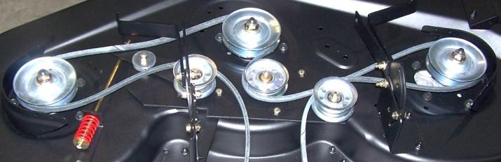
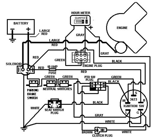
4 BELT ROUTING Deck belt Part# 3816 Transmission Belt# 4220 WIRING DIAGRAM 4


5 DIAGNOSING STARTING PROBLEMS You will notice that each position on the ignition switch sets up a certain section of the total wiring diagram. This section is energized by turning the ignition switch to the start position. The final purpose is to start the engine. The main components are the battery and the starter; the other components are sub-switches to allow the current to get from the battery to the starter. The solenoid is a heavy duty switch, designed to handle the large amount of current needed to crank the engine. That s why the cables are so big; to handle that current. The other switches are for safety purposes to keep the mower from moving; or the blades from turning; until the engine is running and ready to safely start the mowing process. The current needed to energize the solenoid is picked up at one of the large terminals on the solenoid where the positive battery cable is connected. The current travels to the ignition switch by going through the fuse. The B and S contacts are connected inside the switch only when the switch is turned to the crank position. In order to close the contacts inside, the PTO switch has to be turned off; the steering control arms must be pushed outward to close both of the neutral switches; and the parking brake must be engaged to close the brake switch. The current can then energize the coil inside the solenoid to engage the contacts that short against the backside of the two large terminals on the solenoid. This then passes the current from the battery to the starter. Diagnosing a problem then involves making sure that the fuse is good, that all the wires are connected and all switches are activated and making connection to pass the current. STARTER SOLENOID PARKING BRAKE SWITCH NEUTRAL SWITCH ON CONTROL ARM The gray wire connected to the L terminal on the ignition switch is also connected to the B terminal when the switch is turned to the crank position. This wire supplies current to the engine plug where it is sent to the fuel solenoid on the carburetor. This allow fuel to be pulled into the engine. 5

6 DIAGNOSING PTO CLUTCH PROBLEMS The electric clutch can be activated when the ignition switch is in the run position. For the purpose of checking out a problem with the circuit; the engine doesn t have to be running; the switch just needs to be in the run position. First the battery has to have a full charge. Current will flow from the battery to the connecting point at the solenoid. From there it flows through the red wire, through the fuse and onto the ignition switch. If the switch is in the run position, current will flow on to PTO switch. When the PTO switch is pulled on; a connection is made to pass the current to the clutch. For the current to continue on; there must be a good ground connection for the white wire. Checking the circuit is done by following the circuit from the battery to the ground; making sure that all wiring has good connectors and switches are making connection. A voltage meter is a good tool to check for voltage at each connection and each switch. If there is voltage on the brown wire at the clutch, but it still won t engage, you probably have a defective clutch. Make sure it has a good ground on the white wire before you replace it. Apply a negative ground to this terminal Apply 12 volts to this terminal. Clutch should activate, if it doesn t, clutch is defective. 6


7 ENGINE IN NORMAL RUNNING MODE Voltage Regulator First the battery was used to start the engine; and later it will be used to engage the PTO; but with the ignition switch in the run position, and the engine running, the battery is involved in three other function. The red wire coming from the engine plug to the terminal on the solenoid is used by the engine s alternator to charge the battery. The gray wire coming from the L terminal on the ignition switch to the hour meter will drive the meter; but first the green wire has to be grounded. This is done by the pressure switch in the engine; next to the oil filter. When the oil pressure is created by the oil pump; this switch closes and makes a connection to ground for the green wire. Only then does the meter begin to run. Also attached to the gray wire at the hour meter is another gray wire going to the engine plug. It will connect to a gray wire going to the rear of the engine, to the carburetor. It powers the solenoid that opens the carburetor jet. The black wire gives the circuit a ground. 7


8 BATTERY CHARGING SYSTEM Voltage Regulator Red wire goes to the engine plug and then on to the positive terminal of the solenoid to keep the battery charged. Easiest way to check if charging is taking place is to measure the DC voltage of the battery before you start the engine. Then start the engine. Measure the voltage at the battery with the engine running. The voltage should be at least one volt higher right after the engine is started. This voltage will drop a little as the battery gets recharged. To test alternator before it goes to the regulator, unplug the yellow connector and measure the AC voltage across the two gray wires inside this connecter. There should be at least 20 volts AC while the engine is running. SEAT SWITCH IGNITION KILL CIRCUIT The seat switch is designed to kill the ignition on the engine, if the operator leaves the seat, with the PTO engaged. The black wire at the engine plug is connected to the kill wire that goes to the ignition module. Since the M terminal on the ignition switch is also used to kill the engine when the switch is turned off; the seat switch circuit is also connected there. When the PTO is on, a connection is made at that switch to join the M terminal to the seat switch. Now if he leaves the seat, the circuit is completed to ground the ignition module; and the engine shuts down. Whether the operator is on the seat or not, the engine won t start if the seat plug is not completely inserted. The small trigger in the center must be flush with the end of the plug; or the plug itself will cause a short to ground to kill the ignition. PTO SWITCH 8


9 WIRING HARNESS TO ENGINE PLUG CONNECTION Gray wire goes to carburetor fuel solenoid Green wire goes to oil pressure switch Black wire goes to engine ignition module Red wire goes to engine charging system Green wire goes to hour meter Red wire goes to terminal on solenoid with the positive battery cable. Black wire goes to the ignition switch Gray wire goes to hour meter WIRING HARNESS PLUG TO ENGINE Gray wire goes to hour meter Red wire goes to terminal on solenoid with the positive battery cable. Green wire goes to hour meter Black wire goes to the ignition switch. 9


10 DRIVE CONTROL HANDLE ADJUSTMENT Before any adjustments are made to the drive control arms; put an equal amount of air pressure in both rear wheel. If you push both handles forward as far as they will go and they are straight across from each other; but one side is traveling faster than the other; shorten the linkage on the side that is going the fastest. If when you push both handles forward as far as they will go and the traveling speed is the same on both sides so that you are going in a straight line; but one handle is further forward than the other; shorten the linkage on the handle that is further ahead. The adjustment linkage is between the bottom of the control arm and the hydro. There is one on each side of the mower. To adjust, remove the hair pin at the bottom of the control arm. Loosen the jam nut and turn the threads in to shorten the linkage. Reconnect the rod and hair pin and tighten the jam nut. Test drive, and further adjust if needed. PARKING BRAKE ADJUSTMENT The parking brake is a positive lock on the transaxle to keep the mower stable when parked. It is not designed to be used to stop the moving mower. Compare it to the Park position on an automatic transmission in a car or pickup. If it is used to stop the mower while in motion, the cog system will be damaged. It is replaceable; but not a part that will be covered under warranty. It does need to be adjusted periodically. To adjust; jack up one of the rear wheel. Disengage the hydro by pulling back on the yellow handle down below the rear of the engine mounting plate. With the parking brake off; make sure the tooth arm and the cog wheel are close to each other without touching. Adjust the nut on the rod to achieve the clearance. Turn the wheel by hand to see that there is no contact. Now engage the parking brake to see if the two mate to keep the wheel from turning. When adjustment is done; engage the hydro and lower the jack. Repeat the adjustment for the opposite side. Order new parts if tooth arm or cog wheel are damaged. 10


11 DECK REPAIRS A properly adjusted deck should have the blades about 3/8 lower in the front compared to the rear. This adjustment can be made by parking your mower on a level surface and measuring the distance from the blade s cutting edge to the ground. To adjust, loosen the nuts on these bolts. One is located on each of the left and right deck brackets. Position the rear of the deck to achieve the desired 3/8 difference and then retighten the nuts. The deck can be removed by unhooking these bars from the rear deck brackets. By putting the bolts back only into the bars, you can raise the deck lift handle and get these bars out of the way. Also remove this pin from the front of the deck. Unhook the belt from the engine pulley and you can now slide the deck out from under the mower for repairs. If the pulley nut is removed for replacement of the blade spindle assembly; the nut should be re-torque to 60 ft/lbs. Each of the blade spindle assemblies has a grease fitting; they should be greased about every 10 hours of use. When blades are removed for sharpening or replacement; the bottom nut should be torque to 60 ft/lbs. This spring, visible from in front and above the deck, can be tightened to make the deck lift easier. Don t tighten too much or the deck will tend to bounce when mowing rough ground. 11

12 REPLACEMENT PARTS QUICK REFERENCE For additional assistance on service Contact Swisher Mower Co., Inc. Phone Fax
ELECTRICAL. Contents - Wiring Diagrams
 Contents - Wiring Diagrams T-Bar (Floating Deck - Hydro)............................................ 8-16 T-Bar (Fixed Deck - Gear)............................................... 8-17 T-Bar (Fixed Deck
Agri-Fab OWNERS MANUAL. Model No " ROUGH CUT TRAILMOWER. CAUTION: Read Rules for Safe Operation and Instructions Carefully
 Agri-Fab OWNERS MANUAL Model No. 45-0362 CAUTION: Read Rules for Safe Operation and Instructions Carefully Safety Assembly Operation Maintenance Parts 42" ROUGH CUT TRAILMOWER NOTE: Your mower deck will
XL HYDROSTATIC TRANSAXLES
 Purging Procedures Due the effects air has on efficiency in hydrostatic drive applications, it is critical that it be purged from the system. These purge procedures should be implemented any time a hydrostatic
Service Manual. White Outdoor ZT 17. MTD Products LLC - Product Training and Education Department FORM NUMBER /2004
 Service Manual White Outdoor ZT 17 MTD Products LLC - Product Training and Education Department FORM NUMBER 769-01421 9/2004 TABLE OF CONTENTS General Information... 1 Deck Leveling... 1 PTO/Deck Belt
VAGABOND S HANDBOOK TRANSMISSION
 03/24/07 TRANSMISSION Transmission won t engage into Gear This is caused usually by too low a Voltage to get into the ECM. This unit requires a minimum of 9VDC in order to operate at all. Almost all erratic
Service Manual. RZT Zero Turn Rider
 Service Manual RZT Zero Turn Rider NOTE: These materials are prepared for use by trained technicians who are experienced in the service and repair of equipment of the kind described in this publication,
518xi, 520xi & 522xi GARDEN TRACTOR
 FORM NO. 96 58xi, 50xi & 5xi GARDEN TRACTOR MODEL NO. 77 990000 & UP MODEL NO. 75 990000 & UP MODEL NO. 756 990000 & UP SET UP INSTRUCTIONS Loose Parts Use the chart below to identify parts for assembly.
HYDRO-GEAR TRANSAXLE. Hydro-Gear Hydrostatic Transaxle. Transaxle Removal
 Hydro-Gear Hydrostatic Transaxle Internal Service 3. Disconnect the free wheeling valve I rod and the vent hose clamp (Figure 118). Internal service information is contained in the Hydro- Gear Transaxle
Series 1000 and Figure NOTE: The top terminals are showing normally closed at rest and the middle terminals are normally
 38.18.The red wire on the OCR plug carries battery voltage. Behavior: D.C. battery voltage should show-up on a volt meter when the red probe is touched to this terminal and the black probe is grounded,
MODEL x692A REPAIR PARTS HOOD & GRILL
 MODEL 0xA HOOD & GRILL 0 0 0 0 0 0 0 0 MODEL 0xA Screw x0 Dash 00 Trim. 00 Cable Hood Assemnly 00E00 Screw x Lens & Reflector Assembly Cap, Pivot 0 Bolt, Shoulder x 0 Base, Pivot 0 Brace, Right Grille
LAWN & GARDEN PRODUCT ELECTRICAL SYSTEM INFORMATION FOR S 1612
 LAWN & GARDEN PRODUCT ELECTRICAL ELECTRICAL SYSTEM INFORMATION FOR LAWN & GARDEN PRODUCT 106 ELECTRICAL LAWN & GARDEN PRODUCT 20 & 22 BATTERY INFORMATION GENERAL INFORMATION (COURTESY OF HAWKER ENERGY
ATTACHMENTS COMPONENT LOCATION
 42-Inch Mower Deck ATTACHMENTS COMPONENT LOCATION C D E F G H I H G M A B J O K L N M J A - Gage Wheel (Left Front) B - Belt Cover C - Primary Drive Belt D - Flat Idler (fixed) E - Gage Wheel (Right Front)
42B350Z PARTS MANUAL
 4 2 B 3 5 0 Z PARTS MANUAL 64 56 68 2 48 45 30 47 62 26 38 7 35 33 65 43 42 6 16 26 40 31 1 23 14 5 16 19 36 21 20 27 28 24 26 66 22 44 28 29 28 68 34 30 29 32 39 13 17 14 15 12 5 3 4 57 55 54 61 59 60
WARM ENGINE STARTING PROCEDURE
 saw starting COLD ENGINE STARTING PROCEDURE 1. Pull the choke lever out. 2. Lock the throttle in the start position by depressing and holding the throttle lock button (C) while releasing the trigger (A)
Agri-Fab OWNERS MANUAL. Model No " FINISH CUT TRAILMOWER. CAUTION: Read Rules for Safe Operation and Instructions Carefully
 Agri-Fab OWNERS MANUAL Model No. 45-0305 63" FINISH CUT TRAILMOWER CAUTION: Read Rules for Safe Operation and Instructions Carefully NOTE: Your mower deck will require a 12 volt battery to operate. This
521613x89A Garden Tractor (2001) Page 1 of 24 Blade Drive
 Page 1 of 24 Blade Drive") 521613x89A Garden Tractor (2001) Page 1 of 24 Blade Drive 521613x89A Garden Tractor (2001) Page 2 of 24 Blade Drive Ref # Part Number Qty Description 1 094607E701 Cover, Right Pulley 2 26X250 Screw 3 015X84
521613x89A Garden Tractor (2001) Page 1 of 24 Blade Drive 521613x89A Garden Tractor (2001) Page 2 of 24 Blade Drive Ref # Part Number Qty Description 1 094607E701 Cover, Right Pulley 2 26X250 Screw 3 015X84
G3 UHT TRANSMISSION. G3 UHT Transmission Replacement. G3 UHT Transmission Removal
 G3 UHT Transmission Replacement The following procedures cover replacing the left hand UHT Transmission. The same procedures can be followed to remove the right hand UHT Transmission. 5. Raise the seat
Wheel Horse. 52 Mowers. Model No & Up Model No & Up. Operator s Manual
 FORM NO. 9-567 Wheel Horse 5 Mowers for Lawn & Garden Tractors Model No. 7880 890000 & Up Model No. 7885 890000 & Up Operator s Manual IMPORTANT: Read this manual carefully. It contains information about
MODEL 40507x8C REPAIR PARTS CHASSIS & HOOD
 MODEL 007xC CHASSIS & HOOD 2 3 7 9 2 9 2 2 2 27 2 29 32 3 3 37 3 0 39 2 3 7 3 MODEL 007xC CHASSIS & HOOD Seat 90 2 Cap, Push 0n 2x 3 Spring 907 Screw 2x9 Bolt, Wing 0 Washer x7 7 Bolt, Shoulder 9x Support,
HANDLEBAR AND CONSOLE ASSEMBLY
 Section 6 Parts List HANDLEBAR AND CONSOLE ASSEMBLY 4 33 47 4 49 7 3 78 4 97 46 44 37 38 37 48 39 35 36 34 7 3 4 5 45 4 3 4 0 33 9 96 80 6 300 84 9 5 30 4 9 30 4 3 43 97 0 43 3 68 9 9 Models 753B, F753B
Riding Mowers. Z44 and Z52 Accu-Z Razor (S/N and above) SM Service Manual Printed 9/24/09
 SM Service Manual Printed 9/24/09") Riding Mowers Z44 and Z52 Accu-Z Razor (S/N 472620 and above) 23802 357-044SM Service Manual 2006 Printed 9/24/09 Copyright 2006 All rights Reserved Land Pride provides this publication as is without warranty
Riding Mowers Z44 and Z52 Accu-Z Razor (S/N 472620 and above) 23802 357-044SM Service Manual 2006 Printed 9/24/09 Copyright 2006 All rights Reserved Land Pride provides this publication as is without warranty
MODEL 38516x52A REPAIR PARTS CHASSIS & HOOD
 MODEL xa CHASSIS & HOOD 0 MODEL xa Seat Cap, Push 0n x Spring 0 Screw x Bolt, Wing 0 Washer x Z Bolt, Shoulder x Support, Seat E00 Rod, Pivot Z Bracket, Pivot E00 Bolt x Nut x Bolt, Shoulder x Washer Z
Series 1000 and Cutout
 17.15.Remove the belt from the tractor. NOTE: There were a small number of tractors made using a CVT drive and a 2-speed (L-H-N-R) GT transaxle. The belt must pass over the center mounted gear selector
Wheel Horse. 42 Mower. for Lawn and Garden Tractors. Model No & Up. Operator s Manual
 FORM NO. 9 559 Rev A Wheel Horse 4 Mower for Lawn and Garden Tractors Model No. 78 890000 & Up Operator s Manual IMPORTANT: Read this manual carefully. It contains information about your safety and the
MODEL NO & UP
 FORM NO. 97 50xi GARDEN TRACTOR MODEL NO. 7570 990000 & UP SET UP INSTRUCTIONS Loose Parts Use the chart below to identify parts for assembly. DESCRIPTION QTY. USE Rear Wheel Wheel Bolt R.H. Wheel Spindle
MODEL x99A REPAIR PARTS SEAT DECK
 MODEL 0xA F 00L SEAT DECK 0 0 0 0 MODEL 0xA 0 Seat 0E0 Support, Seat 0x Push On Cap 0x Z Washer 000 Bolt, Wing 00x Bolt 00E0 Bracket, Pivot 0X Nut x Screw 0 00 Spring, Leaf x Spring 0 Z Washer, Cup 00x
TimeCutter ZS 5000 Riding Mower
 Form No. 3409-408 Rev A TimeCutter ZS 5000 Riding Mower Model No. 74661 Serial No. 400000000 and Up Register at www.toro.com. Original Instructions (EN) *3409-408* A Ordering Replacement Parts To order
34 DECK ASSEMBLY A. SEE THE DECAL LIST SECTION FOR ALL DECALS /8 STD. FLAT WASHER TENSIONER w/ BUSHING
 3 4 B 1 8 Z PARTS MANUAL 20 21 21 24 24 25 25 26 26 33 34 41 38 39 51 38 37 72 36 43 47 48 44 60 80 35 33 40 50 42 34 30 65 32 66 59 58 57 58 59 18 52 29 49 83 83 17 17 6 7 9 79 50 50 63 72 72 80 64 64
Parts Manual / ZEKH / ZEKH / ZEKH52240
 Parts Manual 99999 / ZEKH00 99999 / ZEKH0 999970 / ZEKH50 MODEL NUMBER SERIAL NUMBER DATE PURCHASED DEALER ADDRESS NOTES: 00 Yazoo/Kees Power Equipment All rights reserved. Beatrice, NE. Printed in U.S.A.
SET-UP INSTRUCTION & PRE-OPERATION CHECKLIST SNAPPER 21" STEEL DECK COMMERCIAL WALK BEHIND MOWERS
 SET-UP INSTRUCTION & PRE-OPERATION CHECKLIST SNAPPER 21" STEEL DECK COMMERCIAL WALK BEHIND MOWERS INTRODUCTION: The SNAPPER Walk Behind Mowers are shipped almost fully assembled and require minimal set-up.
MODEL 40508x92D REPAIR PARTS CHASSIS & HOOD
 MODEL 00x9D CHASSIS & HOOD 9 9 9 9 0 MODEL 00x9D CHASSIS & HOOD Seat 90 Cap, Push 0n x Spring 90 Screw x9 Bolt, Wing 90 Washer xz Bolt, Shoulder 9x Support, Seat 9E00 9 Rod, Pivot 9 Z Bracket, Pivot 9E00
Table of Contents QUICK REFERENCE GUIDE FOR 52B25X...A - 1 DECK COMPONENTS...B - 1 DECK LIFT COMPONENTS... C - 1 FRAME COMPONENTS...
 B X PARTS MANUAL Table of Contents QUICK REFERENCE GUIDE FOR BX...A - DECK COMPONENTS...B - DECK LIFT COMPONENTS... C - FRAME COMPONENTS... D - DRIVE COMPONENTS...E - CONTROL COMPONENTS LINKAGE PARTS...F
ASSEMBLY INSTRUCTIONS
 ASSEMBLY INSTRUCTIONS Read the complete assembly instructions before starting the assembly. You should have: - one mower deck assembly - two carrier arm assemblies - two rear tire assemblies - one ATV
Table of Contents QUICK REFERENCE GUIDE FOR 60K25X...A - 1 DECK COMPONENTS...B - 1 DECK LIFT COMPONENTS... C - 1 FRAME COMPONENTS...
 0 K X PARTS MANUAL Table of Contents QUICK REFERENCE GUIDE FOR 0KX...A - DECK COMPONENTS...B - DECK LIFT COMPONENTS... C - FRAME COMPONENTS... D - DRIVE COMPONENTS...E - CONTROL COMPONENTS LINKAGE PARTS...F
Table of Contents QUICK REFERENCE GUIDE FOR 52K21Z...A - 1 DECK COMPONENTS...B - 1 DECK LIFT COMPONENTS...C - 1 FRAME COMPONENTS...
 5 2 K 2 1 Z PARTS MANUAL Table of Contents QUICK REFERENCE GUIDE FOR 52K21Z...A - 1 DECK COMPONENTS...B - 1 DECK LIFT COMPONENTS...C - 1 FRAME COMPONENTS... D - 1 DRIVE COMPONENTS...E - 1 CONTROL COMPONENTS
42515x92A Lawn Tractor (2000) Page 1 of 17 Chassis & Hood
 Page 1 of 17 Chassis & Hood") 42515x92A Lawn Tractor (2000) Page 1 of 17 Chassis & Hood 42515x92A Lawn Tractor (2000) Page 2 of 17 Chassis & Hood 1 094163 Seat 2 028X23MA Cap, Push On 3 094057MA Spring 4 26X229MA Screw 5 094160 Bolt,
42515x92A Lawn Tractor (2000) Page 1 of 17 Chassis & Hood 42515x92A Lawn Tractor (2000) Page 2 of 17 Chassis & Hood 1 094163 Seat 2 028X23MA Cap, Push On 3 094057MA Spring 4 26X229MA Screw 5 094160 Bolt,
TUFF TORQ TRANSAXLE. Tuff Torq Hydrostatic Transaxle. Transaxle Removal Tuff Torq
 Tuff Torq Hydrostatic Transaxle Internal Service 3. Disconnect the cotter pin and the washer to the brake rod (Figure 63). Internal service information is contained in the Tuff Torq KGIA Transaxle Service
57 ROUGH CUT WITH ELECTRIC CLUTCH BLADE ENGAGEMENT OWNER S MANUAL. With Assembly Instructions For Model: MR55KE
 57 ROUGH CUT WITH ELECTRIC CLUTCH BLADE ENGAGEMENT OWNER S MANUAL With Assembly Instructions For Model: MR55KE KUNZ ENGINEERING, INC. / MENDOTA, IL 61342 / PH (815) 539-6954 01/05 ASSEMBLY INSTRUCTIONS
62 Deck Idler Kit High Speed
 Part No. 00 FORM NO. -899 6 Deck Idler Kit High Speed For Model 70 Serial No. 99000 to 99000 For Model 7 Serial No. 9900 to 99000 INSTALLATION INSTRUCTIONS Loose Parts Note: Use the chart below to identify
WHEEL HORSE LAWN TRACTOR
 FORM NO. 897 WHEEL HORSE LAWN TRACTOR FOR AND 8 MOWERS SET-UP INSTRUCTIONS Loose Parts Note: Use the chart below to verify all parts have been shipped. DESCRIPTION QTY. USE Front Wheel Shim Washer (as
TECHNICAL DATA BROCHURE ZTR 308/3II
 Date 8/84 Page 1 of 6 TECHNICAL DATA BROCHURE ZTR 308/3II IMPORTANT - READ OPERATOR'S MANUAL BEFORE OPERATION OR MAKING ADJUSTMENTS. ' Seat Adjustment Loosen bolts on sliding brackets under each side of
F L CHASSIS & HOOD
 MODEL 3004x2A 102 CHASSIS & HOOD 13 1 2 3 4 6 7 9 10 12 1 1 21 2 27 2 29 32 34 3 37 3 1 40 42 43 44 4 46 47 20 49 70 39 41 0 2 MODEL 3004x2A CHASSIS & HOOD 1 69066 Seat 2 02x Cap, Push 0n 3 09407 Spring
TO THE OWNER ASSEMBLY
 TO THE OWNER This is an operational and general maintenance manual only and does not cover repair. All repair work must be performed by an authorized BOLENS DEALER or the factory warranty is void. Bolens
48 Side Discharge Mower
 FORM NO. 9 7GB Wheel Horse 48 Side Discharge Mower for Lawn & Garden Tractors Model No. 7868 790000 & Up Operator s Manual IMPORTANT: Read this manual carefully. It contains information about your safety
465606x692A Lawn Tractor (2001) Page 1 of 25 Drive Assembly
 Page 1 of 25 Drive Assembly") 465606x692A Lawn Tractor (2001) Page 1 of 25 Drive Assembly 465606x692A Lawn Tractor (2001) Page 2 of 25 Drive Assembly 1 26X249 Screw 2 095315 Knob, Parking Brake 3 711691 Nut, Push 4 1001217 Z Rod, Parking
465606x692A Lawn Tractor (2001) Page 1 of 25 Drive Assembly 465606x692A Lawn Tractor (2001) Page 2 of 25 Drive Assembly 1 26X249 Screw 2 095315 Knob, Parking Brake 3 711691 Nut, Push 4 1001217 Z Rod, Parking
Section 2 - SAFETY MESSAGES AND SYMBOLS
 Section 2 - SAFETY MESSAGES AND SYMBOLS CHOKE "ON" "FAST" RABBIT I CHOKE ] I ENGINE SPEED I CHOKE "OFF" TURTLE "SLOW" 7 Section 2 - SAFETY MESSAGES AND SYMBOLS "START" I BLAOBSENGAGBO"ON" I BLAOBS DISENGAGED
RZT TWIN STICK HYDRO DRIVE 250 Z 44" & 50" SERIES 0
 Parts Manual for RZT TWIN STICK HYDRO DRIVE 250 Z 44" & 50" SERIES 0 MODEL ERZT185440BVE RZT22500BVE2 McDonough, GA, 30253 U.S.A. COPYRIGHT 2006 SNAPPER PRODUCTS, INC. ALL RIGHTS RESERVED. Revision 1,
F L CHASSIS & HOOD
 MODEL 40607x2A 06 CHASSIS & HOOD 3 2 3 4 6 7 8 9 0 2 4 8 9 2 26 27 28 29 3 3 34 3 37 38 40 42 43 44 4 46 47 49 70 2 MODEL 40607x2A CHASSIS & HOOD 69066 Seat 2 028x Cap, Push 0n 3 09407 Spring 4 26x9 Screw
MOWER HOUSING SUSPENSION
 MODEL 000xA MOWER HOUSING SUSPENSION 0 0 0 0 F 00L MODEL 000xA MOWER HOUSING SUSPENSION Knob 00 Washer 0x Pad, Friction 0 Pin, Hanger 0 Link, Lift 00E00 Nut, Flange 0x Bolt, Shoulder 00x Bracket, Rear
57 ROUGH CUT OWNER S MANUAL. With Assembly Instructions For Models: MR55T, MR55B & MR55K
 57 ROUGH CUT MR55K MR55B OWNER S MANUAL With Assembly Instructions For Models: MR55T, MR55B & MR55K KUNZ ENGINEERING, INC. / MENDOTA, IL 61342 / PH (815) 539-6954 1/05 ASSEMBLY INSTRUCTIONS Read the complete
Retro it Steering Column
 Retro it Steering Column INSTALLATION INSTRUCTIONS for 1970-74 Cuda/Challenger FOR PART NUMBER S: 1620810010, 1620810020, 1620810051, 1620820010, 1620820020, 1620820051 S I NCE 1986 Instruction # 8000000005
Safety Instructions & Operators Manual
 Safety Instructions & Operators Manual Congratulations for buying a Country Clipper product. Your Country Clipper Zero Turning Radius Riding Mower was designed and built to provide long and trouble free
HYDRAULIC ASSEMBLY (TL)
") HYDRAULIC ASSEMBLY (TL) REF. REF. 2 3 6 7 0 2 3 7 20 2 22 23 2 2 26 27 2 30 3 32 33 3 3 36 37 3 3 0 2 3 6 3 2 6 2 6 23 6 2 23 HYDRAULIC ASSEMBLY (TL)... 3 076...2... PULLEY 2... 3 077...2... KEY, MM SQ
HYDRAULIC ASSEMBLY (TL) REF. REF. 2 3 6 7 0 2 3 7 20 2 22 23 2 2 26 27 2 30 3 32 33 3 3 36 37 3 3 0 2 3 6 3 2 6 2 6 23 6 2 23 HYDRAULIC ASSEMBLY (TL)... 3 076...2... PULLEY 2... 3 077...2... KEY, MM SQ
52100x92A Garden Tractor (1999) Page 1 of 25 Blade Drive
 Page 1 of 25 Blade Drive") 52100x92A Garden Tractor (1999) Page 1 of 25 Blade Drive 52100x92A Garden Tractor (1999) Page 2 of 25 Blade Drive 1 094607E700 Cover, Right Pulley 2 26X250MA Screw 3 015X84MA Nut 4 037X92MA Belt, Secondary
52100x92A Garden Tractor (1999) Page 1 of 25 Blade Drive 52100x92A Garden Tractor (1999) Page 2 of 25 Blade Drive 1 094607E700 Cover, Right Pulley 2 26X250MA Screw 3 015X84MA Nut 4 037X92MA Belt, Secondary
TimeCutter SS 4225 Riding Mower
 Form No. 3417-390 Rev D TimeCutter SS 4225 Riding Mower Model No. 74726 Serial No. 400000000 and Up Register at www.toro.com. Original Instructions (EN) *3417-390* D Ordering Replacement Parts To order
Table of Contents QUICK REFERENCE GUIDE FOR 48K19X...A - 1 DECK COMPONENTS...B - 1 DECK LIFT COMPONENTS... C - 1 FRAME COMPONENTS...
 4 8 K 9 X PARTS MANUAL Table of Contents QUICK REFERENCE GUIDE FOR 48K9X...A - DECK COMPONENTS...B - DECK LIFT COMPONENTS... C - FRAME COMPONENTS... D - DRIVE COMPONENTS...E - CONTROL COMPONENTS LINKAGE
Table of Contents QUICK REFERENCE GUIDE FOR 42K17Z...A - 1 DECK COMPONENTS... B - 1 DECK LIFT COMPONENTS... C - 1 FRAME COMPONENTS...
 4 2 K 1 Z PARTS MANUAL Table of Contents QUICK REFERENCE GUIDE FOR 42K1Z...A - 1 DECK COMPONENTS... B - 1 DECK LIFT COMPONENTS... C - 1 FRAME COMPONENTS... D - 1 DRIVE COMPONENTS... E - 1 CONTROL COMPONENTS
Auto-Level Troubleshooting (Old Platform) Electronic Control- Prior to 2009, Pressure Switch Control panel #s 2057, 2058, 2795, 2795B
 Electronic Control- Prior to 2009, Pressure Switch Control panel #s 2057, 2058, 2795, 2795B") Auto-Level Troubleshooting (Old Platform) Electronic Control- Prior to 2009, Pressure Switch Control panel #s 2057, 2058, 2795, 2795B This guide addresses the troubleshooting of electronic controls used
Auto-Level Troubleshooting (Old Platform) Electronic Control- Prior to 2009, Pressure Switch Control panel #s 2057, 2058, 2795, 2795B This guide addresses the troubleshooting of electronic controls used
Innovative Racing Electronics
 MPS Fast FI Mixture Control Installation Instructions The MPS Fast FI Mixture Control P/N 1-0337 is a simple means to adjust the fuel curves on your fuel-injected motorcycle. This allows for tuning after
750 Paso Wiring Upgrade
 750 Paso Wiring Upgrade Supplies required: 2 Bosch 30A/12V Relays # #0 332 209 150 (with mounting tab) 1 30 Amp fuse holder 1 10 Amp fuse holder 12 inches of brown 12 gauge wire 60 inches of red 14 gauge
Table of Contents QUICK REFERENCE GUIDE FOR 48K19Z...A - 1 DECK COMPONENTS...B - 1 DECK LIFT COMPONENTS...C - 1 FRAME COMPONENTS...
 4 8 K 1 9 Z PARTS MANUAL Table of Contents QUICK REFERENCE GUIDE FOR 48K19Z...A - 1 DECK COMPONENTS...B - 1 DECK LIFT COMPONENTS...C - 1 FRAME COMPONENTS... D - 1 DRIVE COMPONENTS...E - 1 CONTROL COMPONENTS
INSTRUCTIONS. 20 Circuit Wiring Kit Instructions October 2009, Speedway Motors, Inc.
 1 MAIN FUSE PANEL The main fuse panel harness s designed to be mounted under the dash a the firewall in an area close to the steering column. The enclosed representation of the main dash harness shows
2001 Honda Civic EX ACCESSORIES & EQUIPMENT' 'Cruise Control Systems - Civic & CR-V 2001 ACCESSORIES & EQUIPMENT
 DESCRIPTION 2001 ACCESSORIES & EQUIPMENT Cruise Control Systems - Civic & CR-V Cruise control system uses mechanical and electrically operated devices to maintain vehicle speed settings greater than 25
42516x92B Lawn Tractor (2002) Page 1 of 17 Chassis & Hood
 Page 1 of 17 Chassis & Hood") 42516x92B Lawn Tractor (2002) Page 1 of 17 Chassis & Hood 42516x92B Lawn Tractor (2002) Page 2 of 17 Chassis & Hood 1 094163 1 Seat 2 028X23MA 1 Cap, Push On 3 094057MA 1 4 26X229MA 1 5 094160 1 Bolt,
42516x92B Lawn Tractor (2002) Page 1 of 17 Chassis & Hood 42516x92B Lawn Tractor (2002) Page 2 of 17 Chassis & Hood 1 094163 1 Seat 2 028X23MA 1 Cap, Push On 3 094057MA 1 4 26X229MA 1 5 094160 1 Bolt,
4.0L CEC SYSTEM Jeep Cherokee DESCRIPTION OPERATION FUEL CONTROL DATA SENSORS & SWITCHES
 4.0L CEC SYSTEM 1988 Jeep Cherokee 1988 COMPUTERIZED ENGINE Controls ENGINE CONTROL SYSTEM JEEP 4.0L MPFI 6-CYLINDER Cherokee, Comanche & Wagoneer DESCRIPTION The 4.0L engine control system controls engine
FUEL INJECTION SYSTEM - MULTI-POINT
 FUEL INJECTION SYSTEM - MULTI-POINT 1988 Jeep Cherokee 1988 Electronic Fuel Injection JEEP MULTI-POINT 4.0L Cherokee, Comanche, Wagoneer DESCRIPTION The Multi-Point Electronic Fuel Injection (EFI) system
57 ROUGH CUT OWNER S MANUAL. With Assembly Instructions. For Models: MR55T, MR55B-17.5HP, MR55B-22HP & MR55K
 57 ROUGH CUT MR55K MR55B OWNER S MANUAL With Assembly Instructions For Models: MR55T, MR55B-17.5HP, MR55B-22HP & MR55K KUNZ ENGINEERING, INC. / MENDOTA, IL 61342 / PH (815) 539-6954 1/07 ASSEMBLY INSTRUCTIONS
Parts Manual ZMKW 5222 / ZMKW 6124 /
 Parts Manual ZMKW 222 / 6647801 ZMKW 6124 / 664701 Please read the operator s manual carefully and make sure you understand the instructions before using the machine. MODEL When you need spare parts or
Finishing Mower Estate 72
 Finishing Mower Estate 72 Owners/Operators Manual & Spare Parts List Issue Date: October 2011 1 Introduction Your FIELDMASTER Estate 72 Finishing Mower has been designed to do a range of work to your satisfaction.
Parts Manual. Models: ZCBI48180 MANUAL NO REV. IR (12/01/03)
") Parts Manual Models: ZCBI880 MANUAL NO. 0989 REV. IR (/0/0) INDEX MAIN FRAME ASSEMBLY... - CONSOLE ASSEMBLY... 8 CASTER ASSEMBLY... 9 MOTION CONTROL ASSEMBLY... 0- MOTION CONTROL LEVERS... - DECK LIFT
Parts Manual Models: ZCBI880 MANUAL NO. 0989 REV. IR (/0/0) INDEX MAIN FRAME ASSEMBLY... - CONSOLE ASSEMBLY... 8 CASTER ASSEMBLY... 9 MOTION CONTROL ASSEMBLY... 0- MOTION CONTROL LEVERS... - DECK LIFT
REPAIR PARTS. MODEL x98A CHASSIS & HOOD
 CHASSIS & HOOD 3 9 0 3 9 0 3 9 0 3 3 3 3 3 3 3 3 39 0 3 3 9 CHASSIS & HOOD Seat 90 Cap, Push 0n 0x3 3 Spring 090 Screw x9 Bolt, Wing 000 Washer 0x Z Bolt, Shoulder 009x Support, Seat 09E00 9 Rod, Pivot
Wheel Horse. 44 Snowthrower. for 5xi Lawn and Garden Tractors. Model No & Up. Operator s Manual
 FORM NO. 8 Rev A Wheel Horse Snowthrower for 5xi Lawn and Garden Tractors Model No. 7966 890050 & Up Operator s Manual IMPORTANT: Read this manual, and your tractor manual, carefully. They contain information
1984 Jeep CJ7. IGNITION SYSTEM - SOLID STATE' 'Distributors & Ignition Systems MOTORCRAFT SOLID STATE IGNITION (SSI)
") TESTING SECONDARY CIRCUIT CHECK CAUTION: When checking secondary voltage, do not remove spark plug wires from spark plugs No. 3 on 4-cylinder, No. 1 or 5 on 6-cylinder and No. 3 or 4 on V8 Engines. 1.
TESTING SECONDARY CIRCUIT CHECK CAUTION: When checking secondary voltage, do not remove spark plug wires from spark plugs No. 3 on 4-cylinder, No. 1 or 5 on 6-cylinder and No. 3 or 4 on V8 Engines. 1.
48K19X OPERATORS MANUAL
 4 8 K 1 9 X OPERATORS MANUAL Your mower is only as safe as the operator! Operator carelessness or error may result in serious bodily injury. Improper maintenance of the machine may also result in injury.
57 ROUGH CUT OWNER S MANUAL. With Assembly Instructions For Model: MR55H KUNZ ENGINEERING, INC. / MENDOTA, IL / PH (815) /07
 /07") 57 ROUGH CUT OWNER S MANUAL With Assembly Instructions For Model: MR55H KUNZ ENGINEERING, INC. / MENDOTA, IL 61342 / PH (815) 539-6954 1/07 ASSEMBLY INSTRUCTIONS Read the complete assembly instructions
57 ROUGH CUT OWNER S MANUAL With Assembly Instructions For Model: MR55H KUNZ ENGINEERING, INC. / MENDOTA, IL 61342 / PH (815) 539-6954 1/07 ASSEMBLY INSTRUCTIONS Read the complete assembly instructions
Agri-Fab OWNERS MANUAL. Model No " ROUGH CUT TRAILMOWER. CAUTION: Read Rules for Safe Operation and Instructions Carefully
 Agri-Fab OWNERS MANUAL Model No. 45-03071 45-0361 CAUTION: Read Rules for Safe Operation and Instructions Carefully Safety Assembly Operation Maintenance Parts 42" ROUGH CUT TRAILMOWER the fastest way
TimeCutter SS 4200 Riding Mower
 Form No. 3409-413 Rev A TimeCutter SS 4200 Riding Mower Model No. 74720 Serial No. 400000000 and Up Register at www.toro.com. Original Instructions (EN) *3409-413* A Ordering Replacement Parts To order
CHASSIS & HOOD F L Ihr Ersatzteilspezialist im Internet
 MODEL 000x0A CHASSIS & HOOD 0 0 MODEL 000x0A CHASSIS & HOOD 0 Seat E Hood 0x Washer 0 Bolt, Wing 00x Bolt, Carriage E0 Bracket, Hinge 00x Bolt, Shoulder 00x Bolt, Shoulder Rod, Battery 0x Nut, Flange E0
Installing the PAMCO CB750, CB550, CB500 Four, CB400F and CB350F Ignitions
 Installing the PAMCO CB750, CB550, CB500 Four, CB400F and CB350F Ignitions Section A Removing the Existing Points Plate a1. Remove the points plate and advance mechanism. Follow the instructions in your
Installing Ignition Coil relay
 Installing Ignition Coil relay Above is a schematic diagram of the coil relay modification. All it really does is, it uses the existing 12 Volt positive that normally powers the coils, to power a relay,
Symptom Possible Cause Corrective Action. * Make sure brake isn t stuck in on position. Remove brake parts as necessary to test.
 Troubleshooting Chart for the Hydro-Gear Transaxle Symptom Possible Cause Corrective Action Operates in one direction Inspect control linkage Inspect drive belt and pulleys Unit is Noisy Check oil level
Worldlawn Power Equipment, Inc. Industrial Park 2415 Ashland Ave. Beatrice, NE Toll Free Number:
 Parts Catalog R WYRZ46S/50U/60U Residential Zero Turn Mower Worldlawn Power Equipment, Inc. Industrial Park 2415 Ashland Ave. Beatrice, NE 68310 Toll Free Number: 1-800-267-4255 Table of Contents Table
Table of Contents. Safety symbols... 3 Assembly 6. Operation Maintenance Troubleshooting 11. Storage. 12. Notes. 13
 Table of Contents Safety symbols... 3 Assembly 6 Operation... 8 Maintenance... 10 Troubleshooting 11 Storage. 12 Notes. 13 2 Safety Information Attention; this machine can be dangerous! All operators should
DIAGNOSTIC TROUBLESHOOTING INDEX
 DIAGNOSTIC TROUBLESHOOTING INDEX Curtis Industries, LLC. 111 Higgins Street Worcester, MA 01606 Telephone: (508) 853-2200 Fax: (800) 876-9104 www.snoproplows.com TROUBLESHOOTING INDEX - BY PROBLEM Section
Safety First. Please remember to always use SAFE shop practices when performing all service procedures.
 Safety First Please remember to always use SAFE shop practices when performing all service procedures. 2006 Update Manual January 2006 Country Clipper 2006 Update Manual Index Joystick Kill Switch Oil
CREATIVE EQUIPMENT CC 18 Main Road, Fishers Hill, Germiston, 1401 Tel: Fax:
 FRAME & DRIVE IDLER ASSEMBLY REF # PART # DESCRIPTION 1 MTD603-04680A FRAME ASSY 2 MTD703-05829 DRIVE IDLER ARM 3 MTD710-0520 HEX SCREW, 3/8-16 x 1.5 4 MTD710-3005 HEX SCREW, 3/8-16 x 1.25 5 MTD712-04065
5 Large spring 1. Key Start Kit Workman MDX Utility Vehicle. Preparing the Machine. Loose Parts. No Parts Required. Procedure
 Key Start Kit Workman MDX Utility Vehicle Model No. 119-9534 Form No. 3366-100 Rev B Installation Instructions Note: Determine the left and right sides of the machine from the normal operating position.
Operator s Manual for: MODELS:
 Operator s Manual for: MODELS: ZKWQL42171 ZKWQL48171 ZKWQL48191 ZKWQL42172 ZKWQL42182 ZKWQL48172 ZKWQL48182 ZKWQL48192 ZKWQL48212 ZBIQL48182 Professional Quality Lawn Care Equipment since 1945 Thank you
CHASSIS / FRAME REAR OF MOWER
 CHASSIS / FRAME 23 23 3 2 2 22 2 2 2 2 REAR OF MOWER 20 2 2 2 2 3 CHASSIS / FRAME... 3... 3... PAD-ABRASIVE 2... 3...... FRAME W/DECALS 3... 3 3...... FOOT PLATE W/DECALS...3... 2... KNOB W/STUD... 3 202......
Worldlawn Power Equipment, Inc. Industrial Park 2415 Ashland Ave. Beatrice, NE Toll Free Number:
 Parts Catalog R WYRZ46S/50U/60U Residential Zero Turn Mower Worldlawn Power Equipment, Inc. Industrial Park 2415 Ashland Ave. Beatrice, NE 68310 Toll Free Number: 1-800-267-4255 Table of Contents Table
Z253 Z Master with 62in SFS Side Discharge Mower
 Form No. REV A Z Z Master with 6in SFS Side Discharge Mower Model No. 00000 and Up Parts Catalog Ordering Replacement Parts To order replacement parts, please supply: the part number, the quantity, and
ADD-ON REMOTE STARTER TO AFTERMARKET SYSTEM
 MEGATRONIX RS 110 ADD-ON REMOTE STARTER TO AFTERMARKET SYSTEM Installation and Operation Manual MEGATRONIX CHATSWORTH, CA U.S.A. RS110 ADD-ON REMOTE CAR STARTER For Vehicles Equipped With Automatic Transmission
Wired Real Time GPS Installation Instructions
 Wired Real Time GPS Installation Instructions This page intentionally left blank. TABLE OF CONTENTS 1. Introduction 2 2. Selecting the Mounting Location for the Device. 3 3. Mounting the Device 5 4. Optional
1999 Toyota RAV ACCESSORIES & EQUIPMENT Cruise Control Systems - RAV4
 1999 ACCESSORIES & EQUIPMENT Cruise Control Systems - RAV4 DESCRIPTION WARNING: Deactivate air bag system before performing any service operation. See AIR BAG RESTRAINT SYSTEMS article. DO NOT apply electrical
Wheel Horse. 48 Mower. for Lawn and Garden Tractors. Model No & Up. Operator s Manual
 FORM NO. 5 Wheel Horse 48 Mower for Lawn and Garden Tractors Model No. 786 990000 & Up Operator s Manual IMPORTANT: Read this manual carefully. It contains information about your safety and the safety
A/C PRESSURE MONITOR INSTALLATION INSTRUCTIONS SYSTEM OPERATION GREEN INDICATOR LIGHT
 A/C PRESSURE MONITOR INSTALLATION INSTRUCTIONS Do not attempt to clean or inspect anything while the engine is running. Cleaning and inspection must be done by a certified mechanic. All A/C service must
MSD Kawasaki Jet Ski 750 Enhancer CD Ignition PN 4251
 MSD Kawasaki Jet Ski 750 Enhancer CD Ignition PN 4251 Parts Included: 1 - MSD Enhancer CD Ignition 2-6mm Stainless Steel Flatwashers 2 - Zip Ties Supplies Required For Installation 1 Tube of Blue Loctite
Printed from CyberCat-STIGA Section: GARDEN ELECTRICAL SYSTEM
 Section: GARDEN ELECTRICAL SYSTEM Section: GARDEN ELECTRICAL SYSTEM 2312 2333 1 1 1134-3625-01 Harness 2 1 1134-3623-02.Interlock module 4 2 9849-8013-16 Screw 5 2 1134-3132-01 Cable holder 6 2 1134-3204-01
30500x92A Lawn Tractor (1998) Page 1 of 13 Body Chassis
 Page 1 of 13 Body Chassis") 30500x92A Lawn Tractor (1998) Page 1 of 13 Body Chassis 30500x92A Lawn Tractor (1998) Page 2 of 13 Body Chassis 1 092387 Seat 2 056516E700 Hinge, Seat 3 028X64 Retainer 4 018X16 Lockwasher 5 001X45 Bolt,
30500x92A Lawn Tractor (1998) Page 1 of 13 Body Chassis 30500x92A Lawn Tractor (1998) Page 2 of 13 Body Chassis 1 092387 Seat 2 056516E700 Hinge, Seat 3 028X64 Retainer 4 018X16 Lockwasher 5 001X45 Bolt,
Z Master. 62 Mower. for Z Master Z 255 Traction Unit. Model No & UP. Operator s Manual
 FORM NO. 9 88 Z Master 6 Mower for Z Master Z 55 Traction Unit Model No. 7408 89000 & UP Operator s Manual IMPORTANT: Read this manual carefully. It contains information about your safety and the safety