Snowmobiles PARTS TO BE INSTALLED
|
|
|
- Adelia Norman
- 5 years ago
- Views:
Transcription
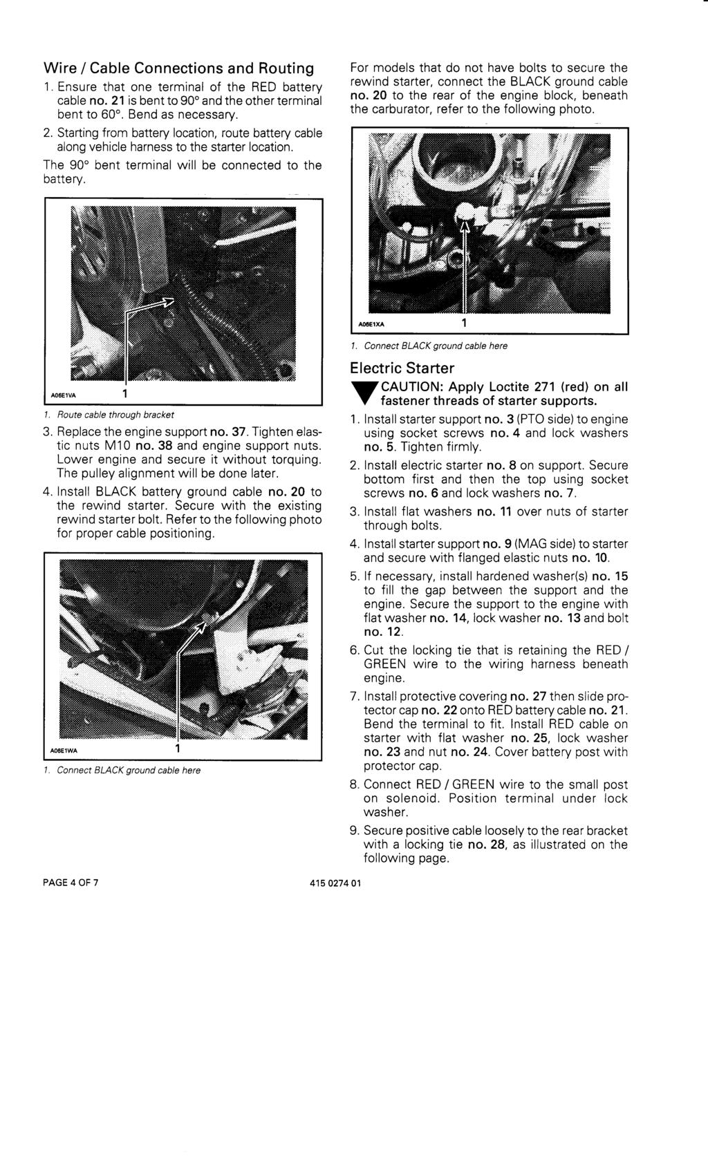
1 TOP ; Snowmobiles WARNING : For safety reasons, this kit must be installed by an authorized Bombardier Ski- Doosnowmobile dealer. Should removal of a locking device be required when undergoing disassembly/assembly, always replace with a new one. This instruction sheet should be given to the purchaser after modification. This kit is designed for specific applicable models only. It is not recommended for snowmobiles other than those for which it was sold. NOTE : Installation time is approximately 3.5 hours. ' PARTS TO BE INSTALLED ELECTRIC STARTER KIT (P/N ) N m (8 lbf ft) N m (35 lbf ft) N m (28 lbf ft) 26 A06EZS Litho d in Canada (MSI9648PRM) *Trademarks of Bombardier Inc. All rights reserved Bombardier Inc PAGE OF 7
. Flat Washer (2) 2. Bolt M8 X 20 3. Lock Washer 4. Flat Washer 5. Hardened Washer (2) 6. Ring Gear 7. Self-Tapping Bolt M6 X 6 (6) 8. Battery Seat 9.")
2 . Regulator/Rectifier 2. Self-Tapping Bolt M6 X 20 (2) 3. Starter Support PTO 4. Socket Screw M8 X 20 (2) 5. Lock Washer (2) 6. Socket Screw M8 X 25 (2) 7. Lock Washer (2) 8. Starter 9. Starter Support MAG 0. Flanged Elastic Nut M5 (2). Flat Washer (2) 2. Bolt M8 X Lock Washer 4. Flat Washer 5. Hardened Washer (2) 6. Ring Gear 7. Self-Tapping Bolt M6 X 6 (6) 8. Battery Seat 9. Pop-Rivet (6) 20. Battery Ground Cable (BLACK) 2. Battery Positive Cable (RED) 22. Protector Cap 23. Lock Washer 24. Nut M8 25. Flat Washer 26. Fuse Holder 27. Protective Covering 28. Locking Tie (7) 29. Battery 30. Battery Cover 3. Battery Strap 32. Battery Strap 33. Machine Screw M5 X Flanged Elastic Nut M5 35. Locking Tie 36. Bolt M8 37. Engine Support 38. Elastic Nut M0 (4) 39. Spacer 40. Carburetor Adapter (2) 4. Pre-formed Heat Shield Deacal VEHICLE PREPARATION Battery ' NOTE : Refer to the Ski-Doo Shop Manual or proper battery removal/installation procedure. Battery must be charged prior to installing this electric starter kit. WARNING : Never charge or boost battery while connected or installed in vehi- ; cle. Vehicle Close fuel shut off valve, if equipped. Remove tuned pipes, muffler, belt guard, drive belt, air intake silencer and carburetors. Loosen drive pulley retaining screw and remove drive pulley from machine. Remove engine support bolts from chassis. Lift engine high enough to ease regulator/rectifier removal. Support the engine using a wooden block. INSTALLATION Regulator/Rectifier. Replace original regulator/rectifier, located along RH side member of frame. Secure the regulator/rectifier no. on both sides using self tapping bolts no. 2 as well as connecting the ground wire from regulator/rectifier. 2 A06ETA. Regulator/Rectifier 2. Connect ground wire here PAGE 2 OF

3 2 2. Apply silicone dielectric grease (P/N ) in the regulator/rectifier connector as well as the vehicle harness connector and plug them together, see following illustration. Ignition Switch. Cut locking tie and unplug connector from ignition switch. Insert the shortest wire of the fuse holder no. 26 inside connector boot. Connect the terminal in position number 7 on the connector A06E05C 2. Regulator/Rectifier ' NOTE : Ensure wire colors are matched asfollows. REGULATOR/ RECTIFIER WIRES RED YELLOW GREEN BLACK VEHICLE WIRES RED / BLUE YELLOW YELLOW / BLACK BLACK A00E4HA. RED/GREEN wire to solenoid 2. BLACK/YELLOW 3. RED wire with fuse to battery 4. BLACK 5. RED/BLUE Replug connector to ignition switch and secure wires with a locking tie no. 28 as illustrated. 5 Ring Gear. Secure ring gear no. 6 on inner half using 6 self tapping bolts no. 7. Apply Loctite 27 (red) on bolt threads. Use Loctite sparringly. CAUTION : Loctite 27 (red) must beap- to properly assemble the ring gear. -plied 2. Torque bolts to N m (97 lbf in) in a crisscross sequence. 3. Do not reinstall drive pulley at this time. A06EUA. Locking tie PAGE 3 OF 7
4
5 0.Pull excess amount of cable from underneath engine..using long locking tie no. 35, secure harnesss to torsion bar under central steering tie-rod as illustrated below. A06I0DA. Tie loosely TOP VIEW A06I0EU PAGE 5 OF 7
6
7 All Models Drive Pulley Refer to the Ski-Doo Shop Manual for proper reinstallation procedure.. Reinstall drive pulley. 2. Check pulley alignment. WARNING : Drive pulley alignment mustalways be checked whenever pulleys ; have been removed, replaced or disassembled. 3. Reinstall remaining removed parts Heat Shield Apply the pre-formed heat shield no. 4 over the existing foam shield on the hood of the vehicle s right hand side. NOTE : Apply Dow Corning sealer no. 736 ' RTV on exhaust manifold ball joint. 4. Test electrical starting and ignition cut-out systems as per normal starting procedure for electric starter models PAGE 7 OF 7
8 Regulator / Rectifier Régulateur / redresseur Self-Tapping Bolt M6 X 20 (2) Boulon autotaraudeur M6 X 20 (2) Starter Support PTO Support de démarreur (côté PDM) Socket Screw M8 X 20 (2) Vis à tête creuse M8 X 20 (2) Lock Washer (2) Rondelle-frein (2) Socket Screw M8 X 25 (2) Vis à tête creuse M8 X 25 (2) Lock Washer (2) Rondelle-frein (2) Starter Démarreur Starter Support MAG Support de démarreur (côté MAG) Flanged Elastic Nut M5 (2) Écrou d arrêt élastique à épaulementm5 (2) Flat Washer (2) Rondelle plate (2) Bolt M8 X 20 Boulon M8 X Lock Washer Rondelle-frein Flat Washer Rondelle plate Hardened Washer (2) Rondelle trempée (2) Ring Gear Couronne de lancement Self-Tapping Bolt M6 X 6 (6) Boulon autotaraudeur M6 X 6 (6) Battery Seat Support de batterie Pop-Rivet (6) Rivet (6) Battery Ground Cable (BLACK) Câble de masse de la batterie (NOIR) Battery Positive Cable (RED) Câble positif de la batterie (ROUGE) Protector Cap Capuchon de protection Lock Washer Rondelle-frein Nut M8 Écrou M Flat Washer Rondelle plate Fuse Holder Porte-fusible Protective Covering Gaine de protection Locking Tie (7) Attache (7) Battery Batterie Battery Cover Couvercle de batterie Battery Strap Bande de batterie Battery Strap Bande de batterie Machine Screw M5 X 20 Vis à métaux M5 X Flanged Elastic Nut M5 Écrou d'arrêt élastique à épaulementm Locking Tie Attache
9 Hex Bolt M8 Boulon hexagonal M Engine Support Support de moteur Elastic Nut M0 (4) Écrou d'arrêt élastique M0 (4) Spacer Entretoise Carburetor Adapter (2) Adaptateur de carburateur (2) Pre-formed Heat Shield Decal Autocollant à écran thermique préformé
BOMBARDIER. ONOTE : Installation time is approximately 3.5 hours. snowmobiles PARTS TO BE INSTALLED
 BOMBARDIER snowmobiles ELECTRIC STARTER KIT (P / N 86 508 00) WARNING : For safety reasons, this kit must be installed by an authorized Bombardier Ski-Doo snowmobile dealer. Should removal of a locking
FOR APPROVAL ONLY. Snowmobiles WARNING PARTS TO BE INSTALLED
 FOR APPROVAL ONLY Snowmobiles For safety reasons, this kit must be installed by an authorized Bombardier snowmobile dealer. Should removal of a locking device be required when undergoing disassembly/assembly,
FOR APPROVAL ONLY. Snowmobiles WARNING PARTS TO BE INSTALLED
 Snowmobiles ELECTRIC STARTER KIT (P/N 86 50 00) FOR APPROVAL ONLY For safety reasons, this kit must be installed by an authorized Bombardier snowmobile dealer. Should removal of a locking device be required
FOR APPROVAL ONLY. Snowmobiles WARNING PARTS TO BE INSTALLED
 Snowmobiles ELECTRIC STARTER KIT (P/N 86 504 00) FOR APPROVAL ONLY For safety reasons, this kit must be installed by an authorized Bombardier snowmobile dealer. Should removal of a locking device be required
FOR APPROVAL ONLY. Snowmobiles WARNING PARTS TO BE INSTALLED
 Snowmobiles REVERSE TRANSMISSION KIT (P/N 860 43 00) FOR APPROVAL ONLY WARNING For safety reasons, this kit must be installed by an authorized Bombardier Ski-Doo snowmobile dealer. Should removal of a
FOR APPROVAL ONLY ; WARNING PARTS TO BE INSTALLED
 FOR APPROVAL ONLY REVERSE TRANSMISSION KIT (P/N 860 43 600) ; WARNING For safety reasons, this kit must be installed by an authorized Bombardier snowmobile dealer. Should removal of a locking device be
Snowmobiles WARNING PARTS TO BE INSTALLED
 Snowmobiles REVERSE TRANSMISSION KIT (P/N 860 433 00). WARNING For safety reasons, this kit must be installed by an authorized Bombardier snowmobile dealer. Should removal of a locking device be required
Snowmobiles PARTS TO BE INSTALLED
 Snowmobiles WARNING :For safety reasons, this kit must be installed by an authorized Bombardier Ski-Doo snowmobile dealer. Should removal of a locking device be required when undergoing disassembly / assembly,
Snowmobiles REVERSE TRANSMISSION KIT (P / N ) Loctite. Original bolt from vehicle. Loctite. Loctite PAGE 1 OF 6
 Loctite. Original bolt from vehicle. Loctite. Loctite PAGE 1 OF 6") Snowmobiles REVERSE TRANSMISSION KIT (P / N 860 48 00) WARNING : For safety reasons, this kit must be installed by an authorized Bombardier snowmobile dealer. Should removal of a locking device be required
Snowmobiles REVERSE TRANSMISSION KIT (P / N 860 48 00) WARNING : For safety reasons, this kit must be installed by an authorized Bombardier snowmobile dealer. Should removal of a locking device be required
FOR APPROVAL ONLY. Snowmobiles WARNING PARTS TO BE INSTALLED
 Snowmobiles EXTENSION KIT (SC-0) (P/N 86 759 00) FOR APPROVAL ONLY WARNING For safety reasons, this kit must be installed by an authorized Bombardier Ski-Doo snowmobile dealer. Should removal of a locking
Snowmobiles WARNING. NOTE: Installation time is approximately 2.2 hours. REVERSE TRANSMISSION KIT (P/N ) PAGE 1 OF 5
 PAGE 1 OF 5") Snowmobiles REVERSE TRANSMISSION KIT (P/N 860 43 500). WARNING For safety reasons, this kit must be installed by an authorized Bombardier snowmobile dealer. Should removal of a locking device be required
Snowmobiles REVERSE TRANSMISSION KIT (P/N 860 43 500). WARNING For safety reasons, this kit must be installed by an authorized Bombardier snowmobile dealer. Should removal of a locking device be required
FOR APPROVAL ONLY. Snowmobiles ; WARNING PARTS TO BE INSTALLED
 FOR APPROVAL ONLY Snowmobiles ; WARNING For safety reasons, this kit must be installed by an authorized Bombardier snowmobile dealer. Should removal of a locking device be required when undergoing disassembly/assembly,
Snowmobiles ; WARNING PARTS TO BE INSTALLED
 Snowmobiles REAR SUSPENSION QUICK ADJUSTMENT KIT 86 7655 00 ; WARNING For safety reasons, this kit must be installed by an authorized Bombardier snowmobile dealer. Should removal of a locking device be
WARNING. Indicates a hazardous situation which, if not avoided, could result in death or serious injury. WARNING
 Floating QRS Short Shaft Conversion (Kit P/N 860 200 832) The following symbols may be used in this document: WARNING Indicates a hazardous situation which, if not avoided, could result in death or serious
Figure A ALSAGROUPE A01 126A0119 Moteur ENGINE
 ALSAGROUPE 7500 Figure A A01 126A0119 Moteur ENGINE A02 126A0120 Bobine START SOLENOID A03 126A0121 Démarreur STARTER A04 126A0122 Rondelle SPRING WASHER A05 126A0123 Vis SOCKET BOLT A06 126A0124 Rondelle
WARNING. Indicates a hazardous situation which, if not avoided, could result in death or serious injury. WARNING
 CVT Cooling System (Kit P/N 860 200 883) The following symbols may be used in this document: WARNING Indicates a hazardous situation which, if not avoided, could result in death or serious injury. CAUTION
Illustrated Parts Manual. ZR 120 Model Number S2005ZRAAAUSG Model Number S2005ZRAAAUSR
 Illustrated Parts Manual ZR 120 Model Number S2005ZRAAAUSG Model Number S2005ZRAAAUSR 2 00 5 TABLE OF CONTENTS 2005 ZR 120 (Model No. S2005ZRAAAUSG) (Model No. S2005ZRAAAUSR) SKI AND SPINDLE ASSEMBLY.................................................
Engine/Moteur 1P70FUA
 Engine/Moteur 1P70FUA 29 21 9 8 15 1 7 2 19 18 1 24 10 28 6 5 4 14 27 16 2 Ref. No./ Réf. Part No./ No. de pièce Description Désignation 1. 951-1068 Fuel Tank Réservoir d essence 2. 951-1069 Flywheel Shroud
AC 120 MODEL NUMBER S2008ACAAAUSG MODEL NUMBER S2008ACAAAUSP
 2008 AC 120 Illustrated Parts Manual MODEL NUMBER S2008ACAAAUSG MODEL NUMBER S2008ACAAAUSP TABLE OF CONTENTS (Model No. S2008ACAAAUSG) (Model No. S2008ACAAAUSP) SKI AND SPINDLE ASSEMBLY... 1 A-ARM ASSEMBLY...
ZR 120 Model NumberS2003ZRAAAUSG
 ARCTIC CAT ZR 120 Model NumberS2003ZRAAAUSG TABLE OF CONTENTS 2003 ZR 120 - Revised (Model No. S2003ZRAAAUSG) SKI AND SPINDLE ASSEMBLY................................................. 1 A-ARM ASSEMBLY..........................................................
Model No. S2002ZRAAAUSG ILLUSTRATED PARTS MANUAL
 A RC TI C C A T 2002 ZR 120 Model No. S2002ZRAAAUSG ILLUSTRATED PARTS MANUAL TABLE OF CONTENTS 2002 ZR 120 (Model No. S2002ZRAAAUSG) SKI AND SPINDLE ASSEMBLY.................................................
Illustrated Parts Manual
 ARCTIC CAT SHARE OUR PASSION. TM Illustrated Parts Manual AC 120 Model Number S2007ACAAAUSG Model Number S2007ACAAAUSO 2007 TABLE OF CONTENTS 2007 AC 120 (Model No. S2007ACAAAUSG) (Model No. S2007ACAAAUSO)
Sno Pro 120. Model Number S2012ACAAAUSG SHARE OUR PASSION.
 2012Snowmobile Illustrated Parts Manual Sno Pro 120 Model Number S2012ACAAAUSG TM SHARE OUR PASSION. TABLE OF CONTENTS 2012 Sno Pro 120 (Model No. S2012ACAAAUSG) SKI AND SPINDLE ASSEMBLY... 1 A-ARM ASSEMBLY...
STX-26 Stump Grinder
 Form No. 3365-311 Rev B STX-26 Stump Grinder Model No. 23210 Serial No. 310000001 and Up Model No. 23210G Serial No. 310000001 and Up Register at www.toro.com. Original Instructions (EN) *3365-311* B Ordering
Use Genuine Spare Parts specified in the parts list for repair and/or replacement. The contents described in the parts list may change due to
 Use Genuine Spare Parts specified in the parts list for repair and/or replacement. The contents described in the parts list may change due to improvement. The drawings of the spare parts are only indicative
CS340ES. Property of - Not for Resale A1
 A1 CYLINDER HEAD - CYLINDER 1 8G8-11111-00-00 HEAD, CYLINDER 1......... 1 2 8G8-11121-00-00 HEAD, CYLINDER 2......... 1 3 NGK-BR9ES-00-00 PLUG, SPARK............. 2 4 8G8-11181-01-00 GASKET, CYLINDER HEAD
Illustrated Parts Manual
 2010 Illustrated Parts Manual 120 Sno Pro Model Number S2010ACAAAUSG SHARE OUR PASSION ṬM TABLE OF CONTENTS 2010 120 Sno Pro (Model No. S2010ACAAAUSG) SKI AND SPINDLE ASSEMBLY... 1 A-ARM ASSEMBLY... 2
XF 800 Sno Pro SHARE OUR PASSION.
 2012Snowmobile Illustrated Parts Manual XF 800 Sno Pro Model Number S2012XFHSPUSG Model Number S2012XFHSPUSO Model Nubmer S2012XFHSPOSG - International Model Number S2012XFHSPOSO - International TM SHARE
71253, XL 440H Lawn Tractor, 2008 (SN ) : BLOWER HOUSING ASSEMBLY BRIGGS AND STRATTON MODEL 31P E1 [1/
 : BLOWER HOUSING ASSEMBLY BRIGGS AND STRATTON MODEL 31P E1 [1/") 71253, XL 440H Lawn Tractor, 2008 (SN 280000001-280999999) : BLOWER HOUSING ASSEMBLY BRIGGS AND STRATTON MODEL 31P777-0133-E1 [1/ Page 1 of 50 71253, XL 440H Lawn Tractor, 2008 (SN 280000001-280999999)
71253, XL 440H Lawn Tractor, 2008 (SN 280000001-280999999) : BLOWER HOUSING ASSEMBLY BRIGGS AND STRATTON MODEL 31P777-0133-E1 [1/ Page 1 of 50 71253, XL 440H Lawn Tractor, 2008 (SN 280000001-280999999)
WARNING. Indicates a hazardous situation which, if not avoided, could result in death or serious injury.
 The following symbols may be used in this document: Supercharger Repair Kit 185 Engine (Kit P/N 420 881 151) 215/255/260 Engines (Kit P/N 420 881 102) WARNING Indicates a hazardous situation which, if
Mid Size Traction Unit
 FORM NO. 3318 701 ProLine Mid Size Traction Unit 18 H.P. Kohler Gear Drive Model No. 30183 790001 & Up Parts Catalog 3318 701 ORDERING REPLACEMENT PARTS To order replacement parts, please supply: the part
STX-26 Stump Grinder
 Form No. 3383-656 Rev B STX-26 Stump Grinder Model No. 23208 Serial No. 314000001 and Up Model No. 23208G Serial No. 314000001 and Up Register at www.toro.com. Original Instructions (EN) *3383-656* B Ordering
INSTALLATION INSTRUCTIONS
 Accessory Application Publication No. INSTALLATION INSTRUCTIONS HORN MOUNT P/N 08Z77-HL4-A00 SXS1000M3/M3P/M5D/M5P Honda Dealer: Please give a copy of these instructions to your customer. MII 15262 Issue
PROCEDURE. Required tools. Drive Pulley Sliding Sheave Removal. No Subject:REV-XP, REV-XR & REV-XU Engine Alignment
 December 22, 2008 Subject:REV-XP, REV-XR & REV-XU Engine Alignment No. 2009-12 YEAR MODEL MODEL NUMBER SERIAL NUMBER 2008 REV-XP All All 2009 REV-XP / REV-XR / REV-XU PROCEDURE Required tools ALIGNMENT
ELECTRIC START KIT KIT P/N
 ELECTRIC START KIT KIT P/N 2873876 Application 2002 Polaris EDGE Models with 500-600 Domestic Engines Before you begin, read these instructions and check to be sure all parts and tools are accounted for.
PARTS CATALOG ODYSSEY INCLUDES MOWER
 PARTS CATALOG 8-3350 ODYSSEY INCLUDES MOWER INDEX PAINT ENGINES GENERAL INFO PRODUCT IDENTIFICATION NUMBERS (P.I.N.) OR SERIAL NUMBERS (S/N) ENGINE MODEL, SERIAL AND SPECIFICATION NUMBERS TRACTOR MODEL
Retriever 5800G/P/D. revised 2/01 Form Number
 Retriever 5800G/P/D PARTS LIST Advance MODELS 56482005, 56482010, 56482015 This parts list is for machines after serial number 221134 All models covered in this manual are OBSOLETE revised 2/01 Form Number
RZT TWIN STICK HYDRO DRIVE 250 Z 44" & 50" SERIES 0
 Parts Manual for RZT TWIN STICK HYDRO DRIVE 250 Z 44" & 50" SERIES 0 MODEL ERZT185440BVE RZT22500BVE2 McDonough, GA, 30253 U.S.A. COPYRIGHT 2006 SNAPPER PRODUCTS, INC. ALL RIGHTS RESERVED. Revision 1,
290 Chain Saw UT A Page 1 of 14 Accessories & Tools
 290 Chain Saw UT-10661-A Page 1 of 14 Accessories & Tools 290 Chain Saw UT-10661-A Page 2 of 14 Accessories & Tools Ref # Part Number Qty S/P/F Description 98293 1 BUMPER SPIKE 98488 1 ROTOR REMOVAL TOOL
1438HXL LAWN TRACTOR
 FORM NO. 3318 846 1438HXL LAWN TRACTOR Model No. 71215 7900001 & Up Parts Catalog 3318 846 ORDERING REPLACEMENT PARTS To order replacement parts, please supply: the part number, the quantity, and the description
EDR-260 Engine Drill EDR-260 Drill moteur
 Accessories for ECHO products can be found at: Pour obtenir des accessoires pour les produits ECHO, consulter notre catalogue d'accessoires à: http://www.echo.ca/products/catalogs PARTS CATALOG NOMENCLATURE
easymotoculture ILLUSTRATED PARTS LIST
 ILLUSTRATED PARTS LIST Use Genuine Spare Parts specified in the parts list for repair and/or replacement. The contents described in the parts list may change due to improvement. The drawings of the spare
17-44HXLE Lawn Tractor
 Form Number 3350-107 17-44HXLE Lawn Tractor Model No. 71283-240000001 and up. Parts Catalog Ordering Replacement Parts To order replacement parts, please supply: the part number, the quantity, and the
FIGURE A R
 FIGURE A 8 7 78 7 8 0 9 7 70 7 8 78 78 9 0 8 7 0 9 7 8 8 9 8 7 0 9 7 0 7 0 9 8 9 7 7 7 7 77 R007 PARTS LIST FOR FIGURE A KEY P/N DESCRIPTION QTY KEY P/N DESCRIPTION QTY 0800090079 Miter Guide Assembly
FORM NO XLE LAWN TRACTOR. Model No & Up. Parts Catalog
 FORM NO. 3319 769 1232XLE LAWN TRACTOR Model No. 71201 8900001 & Up Parts Catalog 3319 769 ORDERING REPLACEMENT PARTS To order replacement parts, please supply: the part number, the quantity, and the description
SOLUTION Depending on the part to be replaced, carefully apply and follow the appropriate procedure. Subject: REV Front End Frame Rebuild Procedure
 Date: February, 2004 Subject: REV Front End Frame Rebuild Procedure No. 2004-0 YEAR MODEL PACKAGE MODEL NUMBER SERIAL NUMBER 2004 All models equipped with REV chassis All All All PROBLEM When the front
Illustrated Parts List to
 Illustrated Parts List Vanguard Model Series 161400 to 161499 TYPE NUMBERS 0010 through 0036, 0040, 0041, 0047, 0049, 0051, 0070, 0073, 0079 through 0085, 0090, 0101, 0110 through 0135, 0199. FORM MS 9877
Illustrated Parts List
 FORM MS 0420 08/11/2004 REPLACES FORM MS 0420 5C 11/2002 FILE IN SECT. 2 OF SERVICE MANUAL 196400 Illustrated Parts List Model Series 196400 TYPE NUMBERS 0004 through 1247. TABLE OF CONTENTS Air Cleaner
Page 1 of HP B&S Vanguard Engine
 1405 Page 1 of 41 14 HP B&S Vanguard Engine 1405 Page 2 of 41 14 HP B&S Vanguard Engine Ref # Part Number Qty S/P/F Description BS-28Q777-0647-E1 1 14 HP B&S Vanguard Engine 1 BS-496412 1 Cylinder Assembly
STX-38 EFI Stump Grinder with Intelli-Sweep
 Form No. 3421-244 Rev A STX-38 EFI Stump Grinder with Intelli-Sweep Model No. 23214 Serial No. 402000000 and Up Register at www.toro.com. Original Instructions (EN) *3421-244* A Ordering Replacement Parts
TECHNICAL DATA BROCHURE ZTR 308/3II
 Date 8/84 Page 1 of 6 TECHNICAL DATA BROCHURE ZTR 308/3II IMPORTANT - READ OPERATOR'S MANUAL BEFORE OPERATION OR MAKING ADJUSTMENTS. ' Seat Adjustment Loosen bolts on sliding brackets under each side of
DVX 90 MODEL NUMBER A2008KSB2BUSD (BLACK-RED) MODEL NUMBER A2008KSB2BUSE (BLACK-CAT GREEN) MORE TO GO ON. TM
 MODEL NUMBER A2008KSB2BUSE (BLACK-CAT GREEN) MORE TO GO ON. TM") 2008 DVX 90 Illustrated Parts Manual MODEL NUMBER A2008KSB2BUSD (BLACK-RED) MODEL NUMBER A2008KSB2BUSE (BLACK-CAT GREEN) MORE TO GO ON. TM TABLE OF CONTENTS Black-Red (Model No. A2008KSB2BUSD) Black-Cat
2008 DVX 90 Illustrated Parts Manual MODEL NUMBER A2008KSB2BUSD (BLACK-RED) MODEL NUMBER A2008KSB2BUSE (BLACK-CAT GREEN) MORE TO GO ON. TM TABLE OF CONTENTS Black-Red (Model No. A2008KSB2BUSD) Black-Cat
rev 6_09/23/14 EK7651H EK7651HD
 D , D 1 Fuel Tank, Handle 258 3 4 7 6 5 2 1 8 9 10 11 13 15 14 12 26 25 27 23 24 20 19 18 17 16 39 38 28 29 22 21 259 41 40 37 36 35 270 32 31 30 34 33 44 46 45 43 48 47 42 50 49 52 51 2 , D 1 Fuel Tank,
TRX-26 Trencher. Model No Serial No and Up * * B. Register at Original Instructions (EN)
") Form No. 3414-278 Rev B TRX-26 Trencher Model No. 22974 Serial No. 400000000 and Up Register at www.toro.com. Original Instructions (EN) *3414-278* B Ordering Replacement Parts To order replacement parts,
Form No. 3414-278 Rev B TRX-26 Trencher Model No. 22974 Serial No. 400000000 and Up Register at www.toro.com. Original Instructions (EN) *3414-278* B Ordering Replacement Parts To order replacement parts,
TECHNICAL DATA BROCHURE ZTR 426
 TECHNICAL DATA BROCHURE ZTR 426 Date 8/84 IMPORTANT - READ OPERATOR'S MANUAL BEFORE OPERATION. Page 1 of 6 Seat Adjustment Loosen bolts on sliding bracket under each side of seat, slide seat forward or
CRAFTSMAN ROTARY LAWN MOWER- - MODEL NUMBER
 CRAFTSMAN ROTARY LAWN MOWER- - MODEL NUMBER 917.376661 59 27 25 19 56 52 \ Co OO 26 14 12 17 / 53 48 50 56 15 25 27 34 35 40 42 51 28!9 30 CRAFTSMAN ROTARY LAWN MOWER- - MODEL NUMBER 917.376661 _0 KEY
ELECTRIC CLUTCH HYDRO DRIVE RMO TRACTORS LT-200 SERIES
 Parts Manual for ELECTRIC CLUTCH HYDRO DRIVE RMO TRACTORS LT-200 SERIES MODEL ELT18538 (2690497) ELT2044 (2690498) LT18538 (2690440) LT18500 (2690518) LT2042 (2690441) LT2044 (2690442) LT22500 (2690443)
ILLUSTRATED PARTS MANUAL/ MANUEL DE PIÈCES DÉTACHÉES
 ILLUSTRATED PARTS MANUAL/ MANUEL DE PIÈCES DÉTACHÉES 277cc ZS 78-SU Horizontal Shaft OHV Snow Engine Moteurs de 277 cm3 ZS 78-SU à arbre horizontal et soupapes en tête MTD Products Ltd., P. O. Box 1386,
MODEL S-32, 3200, ALL AMERICAN
 MODEL S-32, 3200, ALL AMERICAN 1. 1 3201-7001 Chassis Weldment 2. 1 3204-7010 Bell Crank Weld 3. 1 3204-7009 Seconday Lift Weld 4. 1 3204-2018 Primary Lift Arm 6. 1 340-3025-S0 Seat Spring 6. 3 847-2803
Illustrated Parts List
 Illustrated Parts List Hydrostatic Lawn Tractor IMPORTANT: Read safety rules and instructions carefully before operating equipment. Warning: This unit is equipped with an internal combustion engine and
Vacuum Cleaners Vacuum Manuals ASSEMBLY SCHEMATIC MODEL NO. C1810 FOR VACUUM CLEANER PARTS PLEASE CALL
 ASSEMBLY SCHEMATIC 1 39467069 HANDLE N.L.A. 48631149 HANDLE ASSEMBLY COMPLETE 32.39 36222014 WEAR STRIP - LEFT 2.11 2 39454060 HANDLE GRIP 4.48 3 39442017 CORD HOOK 4.31 4 013730-- LOCK RING.38 5 21631301
05-08 GT. Hellion Power Systems Mustang Kit Instructions
 Hellion Power Systems 05-08 Mustang Kit Instructions 1. Disconnect Battery 2. Drain Radiator, keep fluid for re-installation. 3. Remove air box and inlethoses. 6. Next, underneath, punch oil pan for turbo
CYLINDER HEAD - CYLINDER
 A1 CYLINDER HEAD - CYLINDER 1 8AY-11111-00-00 HEAD, CYLINDER 1......... 1 2 8A7-12499-00-00 JOINT................... 1 3 NGK-BR9ES-00-00 PLUG, SPARK............. 2 4 8AY-11181-00-00 GASKET, CYLINDER HEAD
Mid Size Traction Unit
 FORM NO. 3319 398 ProLine Mid Size Traction Unit 14 H.P. Kohler Gear Drive Model No. 30177 695101 Thru 696000 Parts Catalog 3319 398 ORDERING REPLACEMENT PARTS To order replacement parts, please supply:
Edelbrock Victor II Intake Manifold. For Chrysler 5.7L (Eagle) and 6.1L Gen III HEMI Engines Part #7179
 and 6.1L Gen III HEMI Engines Part #7179") For Chrysler 5.7L (Eagle) and 6.1L Gen III HEMI Engines PLEASE study these instructions carefully before beginning this installation. You should be familiar with and comfortable working on your vehicle.
For Chrysler 5.7L (Eagle) and 6.1L Gen III HEMI Engines PLEASE study these instructions carefully before beginning this installation. You should be familiar with and comfortable working on your vehicle.
PARTS LIST WARHORSE 27 & 27 VAC-TRAC
 PARTS LIST WARHORSE 27 & 27 VAC-TRAC PERFORMER WIRING DIAGRAM 248 PERFORMER SERVICE PARTS NSS NO. ONAN NO. DESCRIPTION 6590941 110-3709 GASKET - VALVE COVER 6590951 154-2495 GASKET - INTAKE MANIFOLD 6590961
RMK HANDLEBAR KIT P/N ; ; APPLICATION BEFORE YOU BEGIN KIT CONTENTS. Verify accessory fitment at Polaris.com.
 RMK HANDLEBAR KIT P/N 2883835; 2883836; 2883837 APPLICATION Verify accessory fitment at Polaris.com. BEFORE YOU BEGIN Read these instructions and check to be sure all parts and tools are accounted for.
Mid-Engine Rider. Parts Manual Model Revision 00 TP LT-L
 Mid-Engine Rider Parts Manual Model 7800337 1741802 Revision 00 Rev. Date 05/2008 Table Of Contents PRODUCT COMPONENTS PAGES Steering... 4 Motion Drive... 6 Electrical System... 10 Chassis & Hood... 12
62 Deck Idler Kit High Speed
 Part No. 00 FORM NO. -899 6 Deck Idler Kit High Speed For Model 70 Serial No. 99000 to 99000 For Model 7 Serial No. 9900 to 99000 INSTALLATION INSTRUCTIONS Loose Parts Note: Use the chart below to identify
ILLUSTRATED PARTS MANUAL/ MANUEL DE PIÈCES DÉTACHÉES
 ILLUSTRATED PARTS MANUAL/ MANUEL DE PIÈCES DÉTACHÉES 140 cc 5T65RU OHV Vertical Shaft Engine Moteurs de 140 cm3 5T65RU à arbre vertical MTD Products Ltd., P. O. Box 1386, KITCHENER, ONT. N2G 4J1 PRINTED
SilverPro Series. Lawnmower. Parts Catalog. Form Number Model No and up.
 Form Number 3350-622 SilverPro Series Lawnmower Model No. 10323-240000001 and up. Parts Catalog Ordering Replacement Parts To order replacement parts, please supply the part number, the quantity, and the
MODEL x692A REPAIR PARTS HOOD & GRILL
 MODEL 0xA HOOD & GRILL 0 0 0 0 0 0 0 0 MODEL 0xA Screw x0 Dash 00 Trim. 00 Cable Hood Assemnly 00E00 Screw x Lens & Reflector Assembly Cap, Pivot 0 Bolt, Shoulder x 0 Base, Pivot 0 Brace, Right Grille
7-0 ENGINE REMOVAL 7. ENGINE REMOVAL/INSTALLATION MXU 500
 7 ENGINE REMOVAL SERVICE INFORMATION------------------------------------------------ 7-1 ENGINE REMOVAL ------------------------------------------------------- 7-2 ENGINE INSTALLATION ------------------------------------------------
C PRO MAC /84 to 02/91 IPL R1 Page 1 of 15 Tools And Accessories
 11-400034C PRO MAC 390 06/84 to 02/91 IPL 218037-R1 Page 1 of 15 Tools And Accessories 11-400034C PRO MAC 390 06/84 to 02/91 IPL 218037-R1 Page 2 of 15 Tools And Accessories 214220 Scrench 93797 Wrench
Carburettor. Cylinder. Frame. Engine Brake System. PTO (Power Take-Off) Electrical System. Steering. Seat. Lifting Device.
 Electrical System. Steering. Seat. Lifting Device.") Documents Carburettor Cylinder Frame Engine Brake System Technical information Article number 13-1318-13 Season 1990-1991 Brand Code Stiga Product Name PARK 12HST SubCategory Park Compact Type Machine
Documents Carburettor Cylinder Frame Engine Brake System Technical information Article number 13-1318-13 Season 1990-1991 Brand Code Stiga Product Name PARK 12HST SubCategory Park Compact Type Machine
Illustrated Parts List I Walk Mower Repair Parts Manual
 Illustrated Parts List 2006-01 I0602027 Walk Mower 917.375820. Repair Parts Manual HUSQVARNA ROTARY LAWN MOWER - - MODEL NUMBER 917.375820 REPAIR PARTS 36 37 1 196403 Upper Handle Assembly (Includes Foam
Printed from CyberCat-STIGA Section: GARDEN ELECTRICAL SYSTEM
 Section: GARDEN ELECTRICAL SYSTEM Section: GARDEN ELECTRICAL SYSTEM 2312 2333 1 1 1134-3625-01 Harness 2 1 1134-3623-02.Interlock module 4 2 9849-8013-16 Screw 5 2 1134-3132-01 Cable holder 6 2 1134-3204-01
rev 1_ MH-246.4DS
 rev 1_02-10-15 MH-246.4DS 1 Shaft, Handle, Cutting Attachment 16 9 7 1 8 6 38 11 15 10 3 2 218 4 37 2 1 Shaft, Handle, Cutting Attachment 1 1 660195626 LOOP HANDLE SET POIGNÉE CPL. 1 INC. 6-9,16 1 2 326036-4
SPARE PARTS LIST BRUSHCUTTERS/CLEARING SAWS BC2145,
 SPARE PARTS LIST BRUSHCUTTERS/CLEARING SAWS BC2145, 2008-05 ACCESSORIES BC2145, 2008-05 ACCESSORIES BC2145, 2008-05 Ref Part No Description Remark QTY KIT 1 502 21 60-13 ACCESSORY BAG 1 2 501 60 02-03
ELECTRIC CLUTCH HYDRO DRIVE RMO TRACTORS LT-200 SERIES
 Parts Manual for ELECTRIC CLUTCH HYDRO DRIVE RMO TRACTORS LT-200 SERIES MODEL ELT18538 (2690497) ELT18538 (2690796) ELT18540 (2690781) ELT2044 (2690498) LT18538 (2690440) LT18500 (2690518) LT2042 (2690441)
120 XC SP Model #S01WB1AS Rev. 01. E 2000 Polaris Sales Inc. PARTS MANUAL PN and MICROFICHE PN /00
 0 XC SP Model #S0WBAS Rev. 0 E 000 Polaris Sales Inc. PARTS MANUAL PN and MICROFICHE PN 0/00 C CARBURETOR... B CLUTCH... A CRANKCASE... B D DECALS... A DRIVE TRAIN... A E ELECTRIC DEVICE... B ELECTRICAL
INSTRUCTION, HALDEX PUMP LVS KIT P/N
 LIFT CORPORATION Sht. 1 of 11 DSG# M-06-33 Rev. - Date: 12/17/07 INSTRUCTION, HALDEX PUMP LVS KIT P/N 267923-01 MALE BULLET LVS WIRE HARNESS P/N 267924-01 QTY. 1 LOW VOLTAGE SWITCH (LVS MODULE) P/N 906530-01
REAR ENGINE RIDER 42 MOWER SERIES 22
 Parts Manual for REAR ENGINE RIDER MOWER SERIES MODELS 1BVE CONTENTS DESCRIPTION PAGE(S) DESCRIPTION PAGE(S) WHEELS- TIRES... - FRONT END, STEERING.... - MAIN CASE... - DIFFERENTIAL, R. H. FENDER... 8-9
330 Chain Saw UT Page 1 of 17 Chain Brake and Chain Stop
 330 Chain Saw UT-10609 Page 1 of 17 Chain Brake and Chain Stop 330 Chain Saw UT-10609 Page 2 of 17 Chain Brake and Chain Stop 1 80983 3 SCREW- (8-32 x 1/2) 2 70705 1 STOP- Chain 3 88048 1 SCREW- (10-24
99-04 GT. Hellion Power Systems Mustang GT Kit Instructions
 Hellion Power Systems 99-04 Mustang GT Kit Instructions Part 1 Hellion recommends that the front suspension system be installed either by trained professionals or by 5.Remove rack bolts K-Member Installation
120 XC SP Model #S03WB1AS Rev. 01. E 2002 Polaris Sales Inc. PARTS MANUAL PN and MICROFICHE PN /03
 0 XC SP Model #S0WBAS Rev. 0 E 00 Polaris Sales Inc. PARTS MANUAL PN and MICROFICHE PN /0 This page left blank intentionally. B BLOWER HOUSING... B C CARBURETOR... B CLUTCH... A CONSOLE... A CONTROLS...
Part s Catalog. LX500 Lawn Tractor. Model No. 13AP60RP744. Original Instructions (EN) (01/31/06)
 (01/31/06)") Part s Catalog For Parts Call 0-- or 0-- LX00 Lawn Tractor Model No. AP0RP Original Instructions (EN) -0 (0//0) For Parts Call 0-- or 0-- Model P0RP NUMBER --00 Turf Tire, 0 x 0.0 x -000-00 Rim,.0 x.0-0-0
Part s Catalog For Parts Call 0-- or 0-- LX00 Lawn Tractor Model No. AP0RP Original Instructions (EN) -0 (0//0) For Parts Call 0-- or 0-- Model P0RP NUMBER --00 Turf Tire, 0 x 0.0 x -000-00 Rim,.0 x.0-0-0
Super Recycler Lawn Mower
 Form Number Super Recycler Lawn Mower Model No. 20058-250000001 and up. Parts Catalog Ordering Replacement Parts To order replacement parts, please supply the part number, the quantity, and the description
EUROPEAN REAR ENGINE RIDER SERIES 20
 Parts Manual for EUROPEAN REAR ENGINE RIDER SERIES 20 MODEL E281320BE E331520KVE McDonough, GA, 30253 U.S.A. Briggs & Startton Yard Power Products Group Copyright 2006 Briggs & Startton Corporation Milwaukee,
2017+ L5P Duramax 3 ½ Down Pipe & EGR Fix Kit
 2017+ L5P Duramax 3 ½ Down Pipe & EGR Fix Kit Covers installation of PN s: WCF100630, WCF100829 Note: This Kit is for off road competition use only! Off Road Competition Use Tuning & Exhaust System is
90 Utility Model Number A2013KUB2BUSZ SHARE OUR PASSION.
 2013 90 Utility Model Number A2013KUB2BUSZ TM SHARE OUR PASSION. TABLE OF CONTENTS 2013 ATV 90 (Model No. A2013KUB2BUSZ) BODY PANEL AND HEADLIGHT ASSEMBLY... 1 FRONT AND REAR RACK ASSEMBLY... 2 FRAME AND
TECHNICAL DATA BROCHURE - ZTR 424 & 427 DATE 8/85 PAGE 1 OF 8
 TECHNICAL DATA BROCHURE - ZTR 424 & 427 DATE 8/85 PAGE 1 OF 8 IMPORTANT - READ OPERATOR'S MANUAL BEFORE OPERATION OR MAKING ADJUSTMENTS Deluxe Seat Adjustment Easy hand lever action allows forward and
REAR ENGINE RIDER EUROPEAN SERIES 22
 Parts Manual for REAR ENGINE RIDER EUROPEAN SERIES 22 MODELS E2822BE E2822BE E1522KVE CONTENTS DESCRIPTION PAGE(S) DESCRIPTION PAGE(S) WHEELS, TIRES...2, DRIVE DISC ASSEMBLY... 22 FRONT END, STEERING...4,
Bearcat Z1 XT GS. Model Number S2012BCNWGUSO Model Number S2012BCNWGOSO - International SHARE OUR PASSION.
 2012Snowmobile Illustrated Parts Manual Bearcat Z1 XT GS Model Number S2012BCNWGUSO Model Number S2012BCNWGOSO - International TM SHARE OUR PASSION. TABLE OF CONTENTS 2012 Bearcat Z1 XT GS (Model No. S2012BCNWGUSO)
PROBLEM Timing chain may break causing engine damages. SOLUTION Replace timing chain.
 Campaign no.: 2011 0004 August 9 th, 2011 Subject:Timing Chain Replacement No. 2011-4 YEAR MODEL MODEL NUMBER PARTS GROUP SERIAL NUMBER GTS 130 25BA, 43BA, 43BB 3 GTI 130 23BA, 23BB 3 GTI SE 130 24BA,
PARTS REQUIRED. Engine Mount. Engine Mount Special Tool. Flywheel Bolts
 Campaign no.: 2008 0009 December 5, 2008 Subject:Flywheel Bolts & Engine Mount. No. 2008-6 YEAR MODEL MODEL NUMBER SERIAL NUMBER 2008 DS 450 DS 450 X All See attached list NOTE: Repair all vehicles in
Edelbrock Victor II Intake Manifold. For Chrysler 5.7L (Eagle), 6.1L and 6.4L Gen III HEMI Engines Part #7179
, 6.1L and 6.4L Gen III HEMI Engines Part #7179") For Chrysler 5.7L (Eagle), 6.1L and 6.4L Gen III HEMI Engines PLEASE study these instructions carefully before beginning this installation. You should be familiar with and comfortable working on your
For Chrysler 5.7L (Eagle), 6.1L and 6.4L Gen III HEMI Engines PLEASE study these instructions carefully before beginning this installation. You should be familiar with and comfortable working on your
Z253 Z Master with 62in SFS Side Discharge Mower
 Form No. REV A Z Z Master with 6in SFS Side Discharge Mower Model No. 00000 and Up Parts Catalog Ordering Replacement Parts To order replacement parts, please supply: the part number, the quantity, and
... TX-L MODEL NUMBER CONTENTS 2-3 BODY. 4-6 HOOD ASSEMBLY IGNITION ASSEMBLY. 8-9 SEAT ASSEMBLY STEERING ASSEMBLY.
 .. ~ : l~ :;~, ~ 0 J-I-'olaris I I '. ... TX-L MODEL NUMBER 080639 CONTENTS BODY. HOOD ASSEMBLY IGNITION ASSEMBLY. SEAT ASSEMBLY... STEERING ASSEMBLY. CHAINCASE ASSEMBLY. DRIVE CLUTCH. DRIVEN CLUTCH. DRIVE
INSTALLATION INSTRUCTIONS
 Accessory Application Publication No. INSTALLATION INSTRUCTIONS LED HEADLIGHT P/N 08V71-HL4-A00 SXS1000M3/M3P/M5P Honda Dealer: Please give a copy of these instructions to your customer. MII 15262 Issue