Arrow Shark 2016 M8 II Sterndrive - Collector Edition Owner Manual. M8 II weight: 925 grams Dimensions
|
|
|
- Alexandrina Poole
- 5 years ago
- Views:
Transcription


1 Arrow Shark 2016 M8 II Sterndrive - Collector Edition Owner Manual M8 II weight: 925 grams Dimensions


2 Parts List

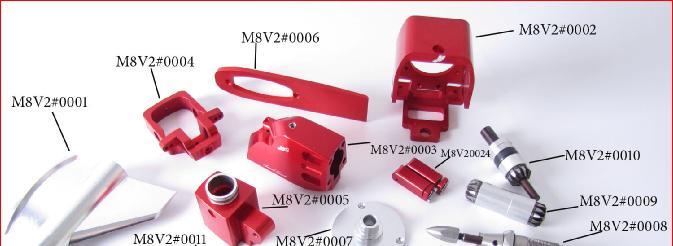
3 M8V2#0001 Billet Lower Unit M8V2#0013 Steering Cable Assembly M8V2#0002 Steering Arm Housing M8V2#0014 M4x8 Bolts x 2 M8V2#0003 Billet Top Unit M8V2#0015 M4x12 Bolts x 8 M8V2#0004 Billet Steering Arm M8V2#0016 M3x16 Bolts x 2 M8V2#0005 Upper Front Unit M8V2#0017 M4x16 & Nut x 1 M8V2#0006 Billet Riding Plate M8V2#0018 M3x20 Bolts x 2 M8V2#0007 Rubber Seal Cover Plate M8V2#0019 M5x25 Bolt x 1 M8V2#0008 Prop Shaft Assembly M8V2#0020 M5x30 Bolt x 1 M8V2#0009 Middle Gear Assembly M8V2#0021 Copper Bush x 4 M8V2#0010 Top Gear Assembly M8V2#0022 M3x8 Bolt x 3 M8V2#0011 Pushrod Cable Sleeve M8V2#0023 Drilling Template M8V2#0012 Rubber Seal M8V2#0024 Pushrod Sleeve Assembly of the M8 II Tools Required #1 Gear Oil #6 3mm Socket Hex Wrench #2 Loctite #7 2mm Socket Hex Wrench #3 21mm Wrench #8 Screw Driver #4 5mm Socket Hex Wrench #9 5mm Short Head Wrench #5 4mm Socket Hex Wrench #10 Pieces of Gas Tube Note: All bolts in the following installation must be applied with loctite.


4 Prop-Shaft Housing Assembly Diagram Top Gear Assembly Diagram


5 Middle Gear Assembly Diagram Step #1: Lower Unit Assembly Prepare the prop-shaft assembly and screw it into the lower unit in left hand direction. Note that when the prop-shaft housing reaches about 15mm from the end, it might stop because - The thread on the lower unit is designed with two levels; the first 15mm of thread has a loose fit while the remainder is a tight fit. So the prop-shaft housing might tighten up at some point between the first and second levels of thread. When that happens, simply rotate the prop-shaft housing left or right a bit until the thread on the housing engages into the second level of thread on the lower unit. Note: Do NOT force the prop-shaft in when you feel it tighten up as that could damage the thread on the lower unit.


.")

6 Apply some loctite on the last 10-15mm thread on the prop-shaft housing; this is a very important step to keep the prop-shaft housing in place, especially for counter-rotation. Note: Before trying to screw the prop-shaft housing out for maintenance, heat the loctite area from outside in order to soften the loctite. Do NOT force it out with a wrench if you feel that it is hard to unscrew. Use a 21mm wrench to tighten the prop-shaft housing into place. Step #2: Top Unit Assembly Apply some gear oil into the lower unit as shown in the picture above (any 2- or 4-stroke oil will work). Place the middle gear assembly into the center hole in the lower unit. Place the riding plate and top unit onto the lower unit; both the top of the lower unit and the bottom of the top unit are installed with seal rings, therefore there is no need for sealant at this time.


7 Place the M5x30 bolt into the back screw hole on the top unit, but do not tighten it at this time. Place the M5x25 bolt into the front hole on the top unit and tighten it with a 5mm hex nut wrench; place the gas tube into the drive in order to avoid any scratch on the part as shown in above picture. And use a short-head 5mm hex nut wrench to tighten both the front and back bolts. Step #3: Front Unit Assembly Push the top gear assembly into the top unit hole. Note: The diameter on the rubber seal is only slightly bigger than the hole in order to prevent oil leakage; therefore, it may need a little force to push it in, or you can try applying a little oil around the rubber seal to make it easier to push in. Connect the front unit to the top unit. Install a piece of gas tube onto the 4mm hex nut wrench to avoid scratching the top unit; use four 4mmx12 bolts to connect the top unit and front unit together.


8 You can use a short-head 4mm hex nut wrench to tighten the bolts. Step #4: Steering Arm Assembly Screw the M4x20 bolt with nut onto the front thread hole on the steering arm as pictured above. Install one of the copper bushes to each side of the steering arm and tighten it with two M4x12 bolts. * Install two M4x8 bolts on each side of the thrust angle adjusting slot as pictured above, but do not tighten it at this time. Step #5: Steering Arm Housing Assembly Install the rubber seal on front unit. Install the steering arm housing onto the steering arm as shown in above picture.


9 Insert a copper bush onto the top of the steering arm housing and tighten it with an M4x8 bolt. Insert another copper bush onto the bottom of the steering arm housing and push the thrust angle adjusting slot to the end as pictured above in order to allow the 4mm hex nut wrench to reach the bolt. Thrust Angle Adjustment After the steering arm housing is installed, adjust the thrust angle to your preferred position, then tighten the Bolt#1 in both sides, and use a 7mm open wrench to tighten the Bolt#2 and nut through the bottom open area shown in the left picture. That is how the thrust angle position is adjusted at anytime during the operation. Step #6: Steering Cable Assembly


10 Match the holes on the pushrod sleeve with the holes on the bottom of the steering arm housing, use a M3x20 bolt to connect them together, making sure the sleeve is moving left and right freely after tightening the bolt; do the same on both sides. Using an M3x16 bolt, connect the steering rod onto the steering arm as pictured above. Do the same on both sides. Step #7: Final Assembly Apply the M3x8mm bolts into the cover in order to tighter it into the steering arm housing. There is an oil inlet on the top unit which seals with an M5 hex nut; screw out the hex nut with a M4 hex wrench when you are ready for an oil refill. Congratulations! Your Installation Is Completed!


11 Drilling the holes on the transom The M8 II comes with a laser-cut wooden template for accurate and easy drilling of the holes on your transom. The holes on the template will match the installation holes on the base of the drive, so all you need do is attach the wooden template to the right position on your transom and drill the installation holes with a 4mm drill. It is recommended that the space between the bottom of the template to the bottom of the keel should be about 25mm, or the prop shaft centerline should be approximately 5 to 8mm above the bottom of the keel, or above the level of the sponsons on a cat. As the M8 II will usually be connected to powerful engines, it is also recommended that the Drive be offset to the right by about 5mm from the keel centerline on the transom to counter the torque from such engines. Higher torque tends to deflect the boat to the right when running, and offsetting the Drive reduces or eliminates this effect, although it is also impacted by the choice of hull and propeller.


12 Twin M8 II Set-Up It is recommended that the spacing for two Drives in a twin M8 II set-up would be 85mm between the two centers of the tie-bar holes as shown in the picture above. With this set-up, you can use up to 80mm diameter props for your boat. We offer a color-matched tie-bar from our website. Steering Cable & Servo Box Set-Up


13 Suggested Servo Box Set-Up Arrow Shark is working on a new version servo box which is specially designed for a twin M8 II set-up. Of course, it will also work for any other RC boat project. The main purpose of the new design is to hold two ¼-scale servos plus one standard servo in the box for a twin M8 installation; most versions of servo box available in the market can hold only up to two ¼-scale servos. This new servo box will be available soon, please check our website for it as a new product update. Below is the suggested servo set-up for a twin M8 application; if you have a similar size servo box, you can try this way but, of course, you can always do it your way - whichever you think would work better! Set-Up #1: Transom Fitting The M8 II comes with flexible steering cables and sleeves with CNC covers on each side of the sleeve. For either single or twin M8 II set-ups, just drill two 5.5mm holes to hold the CNC cable sleeve cover as pictured above, and use some sealant around the hole to prevent water leaking into hull. Set-Up #2: Servo Box Adaptor You will need to custom machine two or four adaptors for the servo box side to hold the other end of the CNC sleeve cover in place for smooth steering operation; below is the suggested dimensions for the adaptor:


; the steel rod must be bent to the correct angle so it connects with the soft cable as straight as")
14 Set-Up #3: ¼-Scale Servo Arm Set-Up We recommend one ¼-scale servo (30 kg with metal gears) for each M8 II steering set up. Both steering cables must be connected to the servo arm as pictured above in order to achieve smooth movement. The plastic servo arm needs to be shortened to the proper length in order to avoid touching the bottom of the servo box. The ¼-scale servo and servo arm adaptor can be ordered from the Arrow Shark website. Set-Up #4: Steering Pushrod Set-Up The pushrod on the M8 II steering set-up must be combined with a steel rod and flexible cable (as shown in above picture); the steel rod must be bent to the correct angle so it connects with the soft cable as straight as possible. The length of the flexible cable should be no more than 10mm from the end point of

15 the cable sleeve adaptor; if the flexible cable is too long, it will cause issues during steering operation. Set-Up #5: Transmitter Set-Up If your RC boat has a single M8 II drive, then you can use any type of 2- or 3-channel RC system for your project. However, for a twin M8 II project, then you should use a 6-Channel stick-type RC system with a Mix Program function. When you install two ¼-scale servos in your servo box side-by-side, the movement of each servo will turn different ways. Therefore, you cannot use a Y type wire adaptor to connect both servos together and plug them both into the 2 nd Channel in your receiver. A 6-Channel receiver with a Mix Program function

16 will allow you to connect one servo to the 2 nd Channel and one servo to the 5 th or 6 th Channel before programming the Mix Function as pictured below: The Mix program set-up could vary on different brands of RC system, but it should be similar to the above. You can test it until you get the proper steering result for the twin M8 movement on both left and right turning. Lower Bearing The bearing in the M8 II lower unit (shown in the picture above) is designed to be a loose fit so that it can be easily removed when you need to replace it. It is held in place by some loctite; therefore every time you change the gear oil and re install the prop shaft housing assembly, make sure this bearing is not loose and is still in place. Make sure there is enough gear oil in the lower every time you use the drive. Thank you! Enjoy your M8 II Sterndrive!
Arrow Shark 2013 Outboard Dragon Drive Owner Manual. Introduction
 Arrow Shark 2013 Outboard Dragon Drive Owner Manual Introduction Our purpose in designing the Dragon Drive is to offer a high quality, sleek looking and durable outboard drive for the growing RC F1 (Formula
Arrow Shark TS760-Marine Onboard E-Starter. Owner Manual
 Arrow Shark TS760-Marine Onboard E-Starter Owner Manual The TS760-Marine Onboard E-Starter has concluded years of experience Arrow Shark has on RC boat onboard E-Starter, it will work for about all brands
Arrow Shark 2015 E-Starter V4 Owner Manual
 Arrow Shark 2015 E-Starter V4 Owner Manual The Arrow Shark E-Starter V3 has successfully been available in the market for over three years now. During that time, we have never stopped seeking ways to improve
Arrow Shark TS 760A E Starter for Gas Cars. Owner s Manual
 Arrow Shark TS 760A E Starter for Gas Cars Starting a Gas Engine Has Never Been So Easy! Owner s Manual The TS 760A is heavy duty equipment with most main components being CNC billet finished and anodized
Thompson Automotive Products
 Installation instructions for Quick-Change Oil Filter relocator for NB (1999+) Miatas (MX-5) Before beginning, get your car up where you have access to the undercarriage (Rhino Ramps work well). Tools
Owner s Manual And Guide To Installation
 Owner s Manual And Guide To Installation < # > TABLE OF CONTENTS 1 How to Use...3 1.1 Control Keypad...3 1.2 Mounting Hardware...4 1.3 Auto Launch Details...5 1.4 Trailering with the SWITCHBLADE...6 1.5
Geared Drives 200Z PSRU Zero Offset Gearbox with Centrifugal Clutch Assembly
 Instructions for Removing and replacing Gen X Gearbox with Geared Drives 200Z Prior to your gear box arriving: Using a strap or chain and an engine hoist to hold your engine up in the mount, remove your
TABLE OF CONTENTS. 1 How to Use Control gauge and Rocker Switch Mounting Hardware... 3
 1 TABLE OF CONTENTS 1 How to Use.... 3 1.1 Control gauge and Rocker Switch... 3 1.2 Mounting Hardware.... 3 1.3Trailering with the SWITCHBLADE... 4 1.4 Maintaining your SWITCHBLADE... 4 2 INSTALLATION
Subaru 5-Speed Double Adjustable Short Throw Shifter
 Subaru 5-Speed Double Adjustable Short Throw Shifter 1999+ Subaru Impreza 5-Speed 2004-2005 Subaru Forester XT 5-Speed Congratulations on your purchase of the COBB Tuning Double Adjustable Short Throw
Installationn Instruction Manual
 Table of Contents Supplied Kit Parts.Page 2 Required Tool List Page 2 Step by Step Installation Instructions Pages 3-6 Battery Requirements.Page 6 Operation Page 7 Maintenance Page 7 Wiring Diagrams..Page
Global West Suspension 655 South Lincoln Ave San Bernardino Ca Phone Fax Web address globalwest.
 Global West Suspension 655 South Lincoln Ave San Bernardino Ca. 92408 Phone 877-470-2975 Fax 909-890-0703 Web address globalwest.net Mustang coilover instruction sheets for 64-66 Kit includes the following
DrVanos.com Stage II Installation Instructions. Tool rental is available with the purchase of a vanos kit *See website for more info*
 DrVanos.com Stage II Installation Instructions Special Tools Needed: Camshaft locking tool TDC Crank pin Sprocket turning tool Tool rental is available with the purchase of a vanos kit *See website for
10A 10F 10B 10E 10A 10D 10B. Mr. T 10C Q R
 Q R 2 0 23 30 12 18 17 16 15 14 37 39 38 3 7 6 5 20 26 21 22 40 13 4 2 25 24 8 1 28 27 11 31 19 10A 10D 10B 10C 10 29 10A 10F 10B 10E 10 9 32 36 33 34 35 178 15 GENERAL 82 80 Ø28.6 ±0.1 Ø30 +0.05 0 348
Jr. T GENERAL. BAM: Bomber Aerospace Material. Special alloy extracted from aerospace material. Ø TRAVEL ±
 175 15 GENERAL The double clamp fork is specifically designed for Downhill use. The fork is sprung by a mechanical spring and uses hydraulic rebound damping. Spring pre-load adjustment controlled via external
OIL COOLER KIT INSTALLATION INSTRUCTIONS PART NUMBER D E92 335is (N54 engine) with BMW M-Technic bumper and with stock oil cooler
 with BMW M-Technic bumper and with stock oil cooler") OIL COOLER KIT INSTALLATION INSTRUCTIONS PART NUMBER D570-0923 APPLICATION: 2011 E92 335is (N54 engine) with BMW M-Technic bumper and with stock oil cooler Congratulations for being selective enough to
OIL COOLER KIT INSTALLATION INSTRUCTIONS PART NUMBER D570-0923 APPLICATION: 2011 E92 335is (N54 engine) with BMW M-Technic bumper and with stock oil cooler Congratulations for being selective enough to
Installation Instructions COMPETITION/PLUS SHIFTER Ford Mustang MT82 6-Speed Manual Transmission Catalog#
 Installation Instructions COMPETITION/PLUS SHIFTER 2015-2017 Ford Mustang MT82 6-Speed Manual Transmission Catalog# 3916037 Rev. 00 WORK SAFELY! For maximum safety, perform this installation on a clean,
3 October 2016 PN# V Dodge Twin Turbo Kit (I-00274) ½ D o d g e 2 4 v I S B
 ½ D o d g e 2 4 v I S B") 3 October 2016 PN#1045320 24V Dodge Twin Turbo Kit (I-00274) 1 DOWNLOAD ENHANCED INSTALL MANUALS AT dieselperformance.com BD Twin Turbo Kit 1998½- 2 0 0 2 D o d g e 2 4 v I S B Part# 1045320 PLEASE READ
3 October 2016 PN#1045320 24V Dodge Twin Turbo Kit (I-00274) 1 DOWNLOAD ENHANCED INSTALL MANUALS AT dieselperformance.com BD Twin Turbo Kit 1998½- 2 0 0 2 D o d g e 2 4 v I S B Part# 1045320 PLEASE READ
Owner s Manual Electric Swivel
 12-225- 11/6/17 1 of 22 Owner s Manual Electric Swivel Onboard Systems International 13915 NW 3rd Court Vancouver, WA 98685 United States of America Cage Code: 1Y921 Toll Free Phone: (8) 275-883 Phone:
MTMANUAL TRANSMISSION GENERAL 1. SPECIFICATIONS. 1) General Specifications. 2) Tightening Torque MANUAL TRANSMISSION
 General Specifications. 2) Tightening Torque MANUAL TRANSMISSION") 03-3 MT GENERAL 1. SPECIFICATIONS 1) General Specifications 2) Tightening Torque 03-4 OVERVIEW AND OPERATION PROCESS 1. OVERVIEW 4WD Features 1. All gears use the helical type and high strength materials.
03-3 MT GENERAL 1. SPECIFICATIONS 1) General Specifications 2) Tightening Torque 03-4 OVERVIEW AND OPERATION PROCESS 1. OVERVIEW 4WD Features 1. All gears use the helical type and high strength materials.
PIRANHA I & 2 INSTALL GUIDE
 TOP Use 5/32" drill bit DO NOT LET DEADRISE INTERSECT THIS LINE PLACE EITHER CORNER ON DEADRISE ANGLE PIRANHA I & 2 INSTALL GUIDE Two components need to be installed on the boat: the transducer and the
OIL COOLER KIT INSTALLATION INSTRUCTIONS PART NUMBER D
 OIL COOLER KIT INSTALLATION INSTRUCTIONS PART NUMBER D570-0904 APPLICATION: 2011-2012 E90 335i/xi (N55 engine) with BMW standard bumper and with stock oil cooler Congratulations for being selective enough
Super T QR20 INSTRUCTIONS GENERAL RULES
 INSTRUCTIONS GENERAL RULES 1. Where specified, assemble and disassemble the shock absorption system using the MARZOCCHI special tools only. 2. On reassembling the suspension system, always use new seals.
Jass.Performance Low Profiles Installation Manual
 Jass.Performance Low Profiles Installation Manual The Jass.Performance Low Profiles are featuring: Fully reversible upgrade of the stock headlight bodies. Premium branded E-signed, TÜV aprooved Hella Headlights
S197 MUSTANG WATTS LINK INFORMATION and INSTALLATION INSTRUCTIONS
 S197 MUSTANG WATTS LINK INFORMATION and INSTALLATION INSTRUCTIONS Watts Link installation instructions for S197 Mustangs. Watts Link for S197 Mustang applications OWNER S INFORMATION and INSTALLATION INSTRUCTIONS
INSTALLATION INSTRUCTIONS FULL HYDRAULIC INSIDE COMPONENTS
 11 Industry Drive Palm Coast, FL 32137 Phone 877.900.7278 Fax 386.445.1122 INSTALLATION INSTRUCTIONS FULL HYDRAULIC INSIDE COMPONENTS 1. Helm and steering column installation (reference. assembly print
UNDERDOG RACING DEVELOPMENT URD Traction Bar Installation
 URD Traction Bar Installation Introduction: UNDERDOG RACING DEVELOPMENT Thank you for choosing the URD Traction Bar for two wheel drive street trucks. More models coming soon! This bar is a true bolt on
VW & Audi TDI CR140 ECO KIT Installation Guide
 VW & Audi TDI CR140 ECO KIT Installation Guide This guide is to help you install your new Rawtek DPF, EGR & Adblue Delete Exhaust ECO Kit on your (2009-2014) VW / Audi with 2.0l CR140 Diesel Engine. Note:
Truckmount Repairs Cat 290 Pump Repair
 Cat 290 Pump Repair COMMON STOCKED PARTS 3 PST101802 Cylinder CAT 290 3 PST26112 Cylinder CAT 280 1 PHY027-004 Oil Filler Cap Black (old 280 & 290 s) 1 PST43211 Oil Filler Cap - Red 1 PST14177 O-ring Oil
PIRANHA 5 INSTALLATION GUIDE
 PIRANHA 5 INSTALLATION GUIDE Two components need to be installed on the boat: the transducer and the control head. The control head displays sonar information, the transducer sends and receives sonar signals
Part # GM G Body Air Suspension System
 350 S. St. Charles St. Jasper, In. 47546 Ph. 812.482.2932 Fax 812.634.6632 www.ridetech.com Part # 11320298 78-88 GM G Body Air Suspension System Front Components: 1 11323001 HQ Series Front Shockwaves
2103 NITRO RAIL DRAGSTER KIT
 203 NITRO RAIL DRAGSTER KIT THANKS FOR BUYING RJ SPEED S NITRO DRAG KIT. IT IS A LITEWEIGHT CAR MADE FOR STRAIGHT LINE DRAG RACING AND CAN BE BROKEN IF RUN INTO SOLID OBJECTS AT HIGH SPEED. YOU WILL NEED
Part # Mustang Complete HQ Series Coil-Over Kit
 350 S. St. Charles St. Jasper, In. 47546 Ph. 812.482.2932 Fax 812.634.6632 www.ridetech.com Front Components: Part # 12090210 64-66 Mustang Complete HQ Series Coil-Over Kit 1 12093509 HQ Series Front Coil-Overs
PIRANHA I & 2 INSTALL GUIDE
 PIRANHA I & 2 INSTALL GUIDE Two components need to be installed on the boat: the transducer and the control head. The control head displays sonar information, the transducer sends and receives sonar signals
Installation Manual TWM Performance Short Shifter Cobalt SS/SC, SS/TC, HHR SS, Ion Redline and Saab 9-3
 Page 1 Installation Manual TWM Performance Short Shifter Cobalt SS/SC, SS/TC, HHR SS, Ion Redline and Saab 9-3 Please Note: It is preferable to park on a flat surface, as you will have to engage and disengage
Adjusting the PRS Z-Axis Bearings
 888-680-4466 ShopBotTools.com Adjusting the PRS Z-Axis Bearings Copyright 2016 ShopBot Tools, Inc. page 1 Copyright 2016 ShopBot Tools, Inc. page 2 Introduction This document describes how to adjust the
Part # Mustang Coil-Over System
 350 S. St. Charles St. Jasper, In. 47546 Ph. 812.482.2932 Fax 812.634.6632 www.ridetech.com Front Components: 1 12093509 HQ Series Front Coil-Overs Part # 12090201 64-66 Mustang Coil-Over System 1 12099599
RJS2021 LTO SPORT OVAL RACER LESS ELECTRICS
 RJS2021 LTO SPORT OVAL RACER LESS ELECTRICS THANKS FOR BUYING THE RJ SPEED 1/10 LTO SPORT KIT FOR OVAL RACING. THE ASSEMBLY WILL NOT BE DIFFICULT IF YOU READ THE TEXT, LOOK AT THE PICTURES, AND THE EXPLODED
GM B-Body Street Grip
 Part # 11015010/11015110-1955-1957 GM B-Body StreetGrip Front Components 11019590 Delrin Control Arm Bushings 90003041 Tall Upper Balljoint 11012350/11012351 Front Dual Rate CoilSprings 22159847 Front
Tools, Equipment and Supplies Needed:
 153-162 DISC BRAKE/DUAL MASTER CYLINDER CONVERSION Please take the time to read the enclosed instructions carefully. If you have any questions, call our Product Assistance personnel for clarifi cation.
RZR Lift Kit. Polaris RZR Part #: Rev
 RZR 570 2 Lift Kit Polaris RZR 570 2012+ Part #: 5101204 Rev. 081916 491 W. Garfield Ave., Coldwater, MI 49036. Phone: 517-278-7768 E-mail: sales-rtpro@sporttruckusainc.com SAFETY WARNING RT Pro UTV recommends
INSTALLATION INSTRUCTIONS
 INSTALLATION INSTRUCTIONS HeliBars Tour Performance Adjustable Handlebar Bridge 2006-2013 Yamaha FJR1300 US & European P/N: HR09079 IMPORTANT: PLEASE GIVE CUSTOMER ENCLOSED INFORMATION! Thank you for your
3M Overhaul Service Kit
 SERVICE INSTRUCTIONS FOR 3M 12,000 RPM 5 in. (127 mm) and 6 in. (150 mm) RANDOM ORBITAL SANDERS 3M Overhaul Service Kit The part number 20347, 3M Overhaul Service Kit, contains all the replacement parts
USE THE PARTS LIST BELOW TO MAKE SURE YOUR KIT IS COMPLETE BEFORE INSTALLATION. IF ANY PIECES ARE MISSING, PLEASE CONTACT:
 1962-1967 Chevy Nova Pro-Touring Front Suspension Installation Instructions Tech line: 1-855-693-1259 www.totalcostinvolved.com Read and understand these instructions before starting any work! USE THE
Air Compressor/Water Pump III - Making the Steam Valves
 Page 1 of 14 Air Compressor/Water Pump Part III Making the Steam Valves Nelson Riedel Nelson@NelsonsLocomotive.com Initial: 1/09/04 Last Revised: 0 The cylinders pistons and water valves were completed
F3P Instruction Manual
 Before use, please read the explanations carefully! F3P Instruction Manual Specifications Fuselage length: 884mm ( 34. Bin ) Wingspan : 845mm ( 33. 2in) Flying Weight : 135-160g (with battery) Additional
COLD AIR INTAKE INSTALLATION INSTRUCTIONS PART NUMBER D A. APPLICATION: E36/7 M-Roadster or M-Coupe 3.
 COLD AIR INTAKE INSTALLATION INSTRUCTIONS PART NUMBER D760-0323A APPLICATION: 1998-00 E36/7 M-Roadster or M-Coupe 3.2 Liter PARTS LIST Air Filter Assembly 3 1/2" Tube Intake Shield Silicone Hose Airflow
LONGTRAVEL SUSPENSION FOR CLUB CAR Model
 INSTALLATION INSTRUCTIONS LONGTRAVEL SUSPENSION FOR CLUB CAR 1980 2003 Model C-7-06 TABLE OF CONTENTS Progressive Suspension Kit... 2 Kit Contents...3-6 Disassembly...7-17 Assembly...18-29 Rack & Pinion
INSTALLATION INSTRUCTIONS
 INSTALLATION INSTRUCTIONS Horizon ST Patented Multi Axis Adjustable Handlebar System for 2012-2015 BMW K1600GTL P/N: HST05078 IMPORTANT: PLEASE GIVE CUSTOMER ENCLOSED INFORMATION! Patent No: US 8,230,758
DISC BRAKE/DUAL MASTER CYLINDER CONVERSION. Tools, Equipment and Supplies Needed:
 Please take the time to read the enclosed instructions carefully. If you have any questions, call our Product Assistance personnel for clarification. It is important to note that these instructions contain
Installation Instructions INDY SHIFTER Fits: Mustang Fastback & Convertible with MT-82 Transmission Catalog #
 Installation Instructions INDY SHIFTER Fits: 2015-2018 Mustang Fastback & Convertible with MT-82 Transmission Catalog # 3916036 Watch our installation video on YouTube WORK SAFELY! For maximum safety,
Pitch Stop Mount Support for WRX/STI
 Pitch Stop Mount Support for 2015+ WRX/STI 2017-02-06 Thank you for purchasing this PERRIN product for your car! Installation of this product should only be performed by persons experienced with installation
INSTALLATION INSTRUCTIONS
 INSTALLATION INSTRUCTIONS 2004-2008 Ducati ST3/ST4 HeliBars Replacement Handlebar Risers P/N: HB2405 IMPORTANT: PLEASE GIVE CUSTOMER ENCLOSED INFORMATION! Thank you for your purchase of our HeliBars. They
928 Specialists Rear Sway Bar Installation
 928 Specialists Rear Sway Bar Installation This document is also available for download on our website (www.928gt.com/rearswaybarinstall.htm). Any new revisions to these original instructions can be found
RJS2020 SPORT 3.2 1/10 PAN CAR KIT LESS ELECTRICS
 RJS2020 SPORT 3.2 1/10 PAN CAR KIT LESS ELECTRICS THANKS FOR BUYING THE RJ SPEED 1/10 SPORT 3.2 KIT. THE ASSEMBLY WILL NOT BE DIFFICULT IF YOU READ THE TEXT, LOOK AT THE PICTURES, AND THE EXPLODED VIEW
J & D Machine / Hyperdrive / MSA 3711 Moon Bend Rd. Chapel Hill, TN 37034
 J & D Machine / Hyperdrive / MSA 3711 Moon Bend Rd. Chapel Hill, TN 37034 www.hyperdriveracing.com 1 You now own a state of the art 1/10 scale oval race car. The Hyperdrive Assault has gone through months
Hand Pallet Truck NC. Operation Manual
 Hand Pallet Truck -------NC Operation Manual Operation Manual 1 Application Range This product is suitable for using in rated load of up to 5500lbs. This PL5500HD is the perfect jack for handling palletized
Instruction Manual. Specifications are subjected to change without notice due to product continuous improvements.
 Instruction Manual Specifications are subjected to change without notice due to product continuous improvements. 1 The Wargo Signature Yak 55 is the realization of my goal to have the perfect 3D and aerobatic
Bearing and Seal Installation Tool T1 Clutch Assembly Stand X X X X Shift Handle Tool X X T Bearing Cup Driver X X
 Bravo Sterndrive Bravo Sterndrive Tool Application Chart Part No. Description Bravo One Bravo Two Bravo Three Blackhawk 11 24156 Hex Nut 12 34961 Washer 91 12427 Shift Cable Adjustment Tool 91 17256 Bearing
Version 1.4 Operating instructions Czech Republic
 Version 1.4 Operating instructions Czech Republic Please check updates of operating instructions at www.rotomotor.cz, that your engine has still the best care. (can happen important changes that will lead
Part # Chevy Level 2 CoilOver Suspension Package Two Piece Frame
 350 S. St. Charles St. Jasper, In. 47546 Ph. 812.482.2932 Fax 812.634.6632 www.ridetech.com Part # 11030210 55-57 Chevy Level 2 CoilOver Suspension Package Two Piece Frame Front Components: 1 11013510
INSTALLATION GUIDE. Doc ID: C Doc Rev:
 REKLUSE MOTOR SPORTS The Rekluse Core EXP Kit INSTALLATION GUIDE Doc ID: 191-7700C Doc Rev: 012213 2012 Rekluse Motor Sports Rekluse Motor Sports, Inc. 12000 W Franklin Rd Boise, Idaho 83709 208-426-0659
PYRTE. Building The Front Axle, Fork and Steering
 PYRTE Building The Front Axle, Fork and Steering The front axle on this traction engine is a very simple affair, in that it is a rectangular steel rod, sat on edge, with a pivot in the centre, which is
RZR 900S/4, 1000S 1.5 Lift Kit
 RZR 900S/4, 1000S 1.5 Lift Kit Polaris RZR 900S/4, 1000S 2015+ Part #: 5101255 Rev. 082316 491 W. Garfield Ave., Coldwater, MI 49036. Phone: 517-278-7768 E-mail: sales-rtpro@sporttruckusainc.com SAFETY
Please take to time to read the provided manufacturers literature for the cordless drill and Masterflex EasyLoad 3 pump head.
 MHEproducts.com DrillPump3 Instruction Manual Ver. 1.00, July, 3 2018 DRAFT Congratulations! We hope that you enjoy your new DrillPump Model 3, and that it will assist you with your field work for many
INSTALLATION INSTRUCTIONS ADD ON INSIDE COMPONENTS USING SAGINAW SHUTTLE VALVE
 11 Industry Drive Palm Coast, FL 32137 Phone 877.900.7278 Fax 386.445.1122 INSTALLATION INSTRUCTIONS ADD ON INSIDE COMPONENTS USING SAGINAW SHUTTLE VALVE 1. Modifying Mercury shuttle valve Located at the
Shown with optional GFR-1017R Body Posts. J & D Machine / Hyperdrive / MSA 3711 Moon Bend Rd. Chapel Hill, TN
 Shown with optional GFR-1017R Body Posts J & D Machine / Hyperdrive / MSA 3711 Moon Bend Rd. Chapel Hill, TN 37034 www.hyperdriveracing.com 1 You now own a state of the art 1/10 scale oval race car. The
Shotgun Single Barrel HPFP install guide
 Shotgun Single Barrel HPFP install guide Thank you for your purchase of the VTT Shotgun Single Barrel HPFP upgrade! First thing to do when you open your box is to make sure all parts are in their respective
BBK LONG TUBE HEADERS (99-04 GT, Mach 1, Bullitt)
") BBK LONG TUBE HEADERS (99-04 GT, Mach 1, Bullitt) Install Time: Approx. 8-10 hrs Parts Needed: BBK Long Tube Headers Shorty mid pipe X/H O2 wiring harness extensions Hi-temp thread locker Tools Required:
BBK LONG TUBE HEADERS (99-04 GT, Mach 1, Bullitt) Install Time: Approx. 8-10 hrs Parts Needed: BBK Long Tube Headers Shorty mid pipe X/H O2 wiring harness extensions Hi-temp thread locker Tools Required:
Gearbox assembly manual
 There are no propellor forces (axial load) allowed to the output shafts, more informations at the end of this manual Gearbox assembly manual Dear friend of fast boats, you have bought a gearbox kit. With
Ford E350/E450 Super Duty (2004-present) Part #SSR ~ SSR ~ SSR Installation Instructions
 Part #SSR ~ SSR ~ SSR Installation Instructions") Ford E350/E450 Super Duty (2004-present) Part #SSR-106-40-1 ~ SSR-106-47-1 ~ SSR-106-54-1 Installation Instructions Drivers side (Passenger s side similar) Parts List Item Part # Description Qty. A 512067/8
Ford E350/E450 Super Duty (2004-present) Part #SSR-106-40-1 ~ SSR-106-47-1 ~ SSR-106-54-1 Installation Instructions Drivers side (Passenger s side similar) Parts List Item Part # Description Qty. A 512067/8
SE206 Installation & Removal Guide
 SE206 Installation & Removal Guide Tools Needed: Sockets 5/8" socket 9/16" socket 1/2 socket 18mm 3/8 socket 1-1/16 socket Wrenches 5/8" wrench 1/2" wrench Sealers/ Lubricants Grease Silicone sealant Gear
OIL COOLER KIT INSTALLATION INSTRUCTIONS PART NUMBER D E92 335i/xi (N55 engine) with BMW Standard bumper and with stock oil cooler
 with BMW Standard bumper and with stock oil cooler") OIL COOLER KIT INSTALLATION INSTRUCTIONS PART NUMBER D570-0924 APPLICATION: 2011-12 E92 335i/xi (N55 engine) with BMW Standard bumper and with stock oil cooler Congratulations for being selective enough
OIL COOLER KIT INSTALLATION INSTRUCTIONS PART NUMBER D570-0924 APPLICATION: 2011-12 E92 335i/xi (N55 engine) with BMW Standard bumper and with stock oil cooler Congratulations for being selective enough
Sisu S-Cam Drum Brakes
 Sisu S-Cam Drum Brakes (For hub reduction rear axles since 1992) Maintenance Manual Sisu Axles, Inc. Autotehtaantie 1 P.O. Box 189 FIN-13101 Hämeenlinna Finland Phone int + 358 204 55 2999 Fax int + 358
Camaro Torque Arm Install Instructions
 1967-1969 Camaro Torque Arm Install Instructions 1-800-984-6259 www.totalcostinvolved.com 67 [429-4202-00] OR 68-69 [429-4202-00] REAR BRACKETS BARS Shocks Includes: Includes: Includes: Includes: 1 REAR
INSTALLATION GUIDE DYNAMIC TRIM CONTROL SYSTEM SERIES S
 INSTALLATION GUIDE DYNAMIC TRIM CONTROL SYSTEM SERIES S TOOLS Power drill Drill bits Hole saw Screw bits Ø 2.5 mm (3/32 ) Ø 3 mm (1/8 ) Ø 3.5 mm (9/64 ) Ø 4 mm (5/32 ) Ø 5 mm (3/16 ) Sealant Ø 19 mm (3/4
AKRAPOVIC RACING & EVOLUTION EXHAUST SYSTEM for the Kawasaki Ninja ZX-6R Kawasaki 636 Ninja ZX-6R
 Installation instructions: *502181* AKRAPOVIC RACING & EVOLUTION EXHAUST SYSTEM for the Kawasaki Ninja ZX-6R Kawasaki 636 Ninja ZX-6R Congratulations on purchasing an Akrapovic exhaust system. Please read
Assembly and Operating Manual
 Dear customer, Assembly and Operating Manual The radio control system Glued joints, suitable adhesives Congratulations on your choice of a factory-assembled model aircraft from the SKYANGEL Hummingbird
Installation Manual TWM Performance Short Shift Kit Stage 1 and Stage 2 MazdaSpeed 6
 Page 1 Installation Manual TWM Performance Short Shift Kit Stage 1 and Stage 2 MazdaSpeed 6 Please Note: It is preferable to park on a flat surface, as you will have to engage and disengage the hand brake
RS-2 SINGLE ACTION REAR BUMPER WITH TIRE CARRIER INSTALL MANUAL FOR JEEP WRANGLER ALL MODELS.
 RS-2 SINGLE ACTION REAR BUMPER WITH TIRE CARRIER INSTALL MANUAL FOR 2007-2016 JEEP WRANGLER ALL MODELS. Rear Bumper Installation Instructions 1) Remove factory rear bumper, (this includes all tow hitch
In summary, the procedures includes removal of the belly pans, draining of the engine block, draining of the radiator, coolant mixing and refilling.
 COOLANT DRAIN AND CHANGE PROCEDURE Recently, there was a request for a picture guide for draining/changing coolant (Robot808 and James-man) and since I was going to do this operation on Idaho (88), I took
2017 Current Ford SuperDuty Adaptive Cruise Control Relocation Bracket Installation Instructions
 2017 Current Ford SuperDuty Adaptive Cruise Control Relocation Bracket Installation Instructions PREPARATION 1. Disconnect the negative terminal on the battery. Park the vehicle on level ground and set
GP1-R FULL EXHAUST SUZUKI GSX-R600 / GSX-R
 THIS EXHAUST SYSTEM IS DESIGNED FOR USE IN CLOSED COURSE RACING ONLY, AND IS NOT INTENDED FOR PUBLIC HIGHWAY USE. IN THE STATE OF CALIFORNIA, IT IS ILLEGAL TO MODIFY THE EMISSION CONTROL SYSTEM ON ANY
Service Manual Blue Giant
 R 2000 Service Manual Blue Giant Models PT-50 and PT-55 Developed by Super Stores Service This manual is intended for basic service and maintenance of the Blue Giant pallet jack. The pallet jacks you are
Single Barrel Shotgun HPFP Install Guide
 Single Barrel Shotgun HPFP Install Guide Thank you for purchasing the VTT Single Barrel Shotgun HPFP upgrade kit! PLEASE READ THE ENTIRE GUIDE BEFORE BEGINNING INSTALLATION! The first thing you should
IMCO SCX SERIES INFORMATION, OPERATION & MAINTAINANCE
 IMCO SCX SERIES INFORMATION, OPERATION & MAINTAINANCE Warning! Warning! Warning! Danger! Warning! 1. SCX & SCX4 Drives will not fit on a standard gimbal helmet, IMCO HELMET: #05-8025 Black or #05-8027
James Barone Racing Aftermarket Parts and Accessories
 Page1 James Barone Racing Aftermarket Parts and Accessories What you will need: Jack and Jack Stands Drill 1/8 and 1/4 drill bits Ratchet wrench 11mm socket Philips head screw driver Flat head screw driver
Installation instruction do88 Performance Radiator for Volvo S60 V70 XC70 S
 Installation instruction do88 Performance Radiator for Volvo S60 V70 XC70 S80 00-09 1. This instruction shows how to replace the OEM radiator with do88 performance radiator. At this type of installation
Chevy Nova Pro-Touring Front Suspension Installation Instructions
 1962-1967 Chevy Nova Pro-Touring Front Suspension Installation Instructions 1-800-984-6259 www.totalcostinvolved.com 1 Pro-Touring Clip A-Arm Assembly Sway Bar Assembly Fender Panel Kit 8 7/16-20 * 1 ¼
Introduction Warning Suggested Field Equipment and Supplies Contents of Kit Section 1: Building the Boat Stand...
 TM INSTRUCTION MANUAL Overall Length...................... 61 1 /2" Hull Length......................... 55" Beam............................ 14 3 /4" Weight.......................... 14.5 lb Speed..........................
Note: Replace the washer and the spacer above the turgo or the shaft adapter with the spacer above the washer as shown in the following pictures.
 BEARINGS, SERVICE & ASSEMBLY IMPORTANT Bearing maintenance is important. You should replace bearings ONCE PER YEAR or as soon as you notice any looseness from wear. If they are too loose, severe damage
Kodak 750H Carousel Projector Repair
 Kodak 750H Carousel Projector Repair An AT YOUR OWN RISK PROJECT by Klaus Wolter, Rev B, 3-26-2016 Here I documen the repair of my 750H carousel. A common problem with this projector, and all of the projectors
Subaru Front Mount Intercooler Kit STI Subaru Front Mount Intercooler Kit STI
 Subaru Front Mount Intercooler Kit STI 2008-2014 715500 Subaru Front Mount Intercooler Kit STI 2008-2014 Congratulations on your purchase of the Subaru Front Mount Intercooler Kit STI 2008-2014. The following
RADIO CONTROL MODEL ASSEMBLY INSTRUCTIONS. Wasp
 RADIO CONTROL MODEL ASSEMBLY INSTRUCTIONS Wasp TRAINER Almost ready-to-fly Wingspan 1520mm Fuselage length 1105mm Engine: 40-46 2T / 52-60 4T Electric Motor: 600-700W Radio: 5 channel / 4-5 servo RC Functions:
The Life of a Lifter, Part 2
 Basics Series: The Life of a Lifter, Part 2 -Greg McConiga Last time we looked at some complicated dynamics and compared flats to rollers. Now for the hands-on. 6 FEATURE This off-the-shelf hydraulic lifter
Part # Mustang Tru-Turn Suspension Package
 350 S. St. Charles St. Jasper, In. 47546 Ph. 812.482.2932 Fax 812.634.6632 www.ridetech.com Part # 12099599 64-66 Mustang Tru-Turn Suspension Package Front Components: 1 12093699 Upper Strong Arms 1 12092899
Installation instructions
 Installation instructions Akrapovič Exhaust System: Evolution for the Ducati 1199 Panigale Ducati 1199 Panigale S Ducati 1199 Panigale R *503760* www.akrapovic.com www.akrapovic.com Congratulations on
Z5 Coil (80) GENERAL. BAM: Bomber Aerospace Material. Special alloy developed from aerospace material. Ø TRAVEL 80 55
 GENERAL. BAM: Bomber Aerospace Material. Special alloy developed from aerospace material. Ø TRAVEL 80 55") (8) 175 8 Ø3 +.5 L.MAX=461 L.L.=451 L.MIN=371 ±2 396 ±2 TRAVEL 8 55 18 Ø3 15 2 -.1 +1 248.5 GENERAL The fork is sprung by a mechanical coil system and uses hydraulic rebound damping. Spring pre-load adjustment
(8) 175 8 Ø3 +.5 L.MAX=461 L.L.=451 L.MIN=371 ±2 396 ±2 TRAVEL 8 55 18 Ø3 15 2 -.1 +1 248.5 GENERAL The fork is sprung by a mechanical coil system and uses hydraulic rebound damping. Spring pre-load adjustment
M52tu-M54 VANOS Assembly & Timing Using G.A.S. Professional Cam Tool Kit
 Home BMW Solutions Porsche Solutions DIY Tech Engine Services Dyno Services Machining About Contact Store Tool Rental M52tu-M54 VANOS Assembly & Timing Using G.A.S. Professional Cam Tool Kit This procedure
Installation Instructions Mustang Air Suspension. Part # Mustang Air Suspension System.
 Part # 12120298-1979-1989 Mustang Air Suspension System Recommended Tools Front Components: 12122401 Front ShockWave Strut Rear Components: 12125401 RearShockWave 12125899 Rear Lower StrongArms 12126699
installation manual 123\TUNE+-2CV
 installation manual 123\TUNE+-2CV Installation Instructions The 123\TUNE+-2CV is designed for the stock (BLACK) 2CV-coil STEP 1 Turn the ignition off. Remove the engine fan use a long 14 mm socket or