INSTALLATION INSTRUCTIONS
|
|
|
- Leo Phillip Bond
- 5 years ago
- Views:
Transcription
1 INSTALLATION INSTRUCTIONS HeliBars Tour Performance Adjustable Handlebar Bridge Yamaha FJR1300 US & European P/N: HR09079 IMPORTANT: PLEASE GIVE CUSTOMER ENCLOSED INFORMATION!
2 Thank you for your purchase of our HeliBars. They are designed to increase your long distance comfort and improve the handling of your sport motorcycle, and we feel confident you will enjoy them. Your HeliBars are designed to fit your motorcycle with little to no modifications needed to your stock cables and hydraulic lines. In order to achieve this fit, we do not simply increase the height at the fork tube/triple clamp area. If we were to mirror the angle of your stock handlebars, the HeliBars would not fit and clear your stock equipment, and lock to lock steering clearance would be impossible. If you hold up the HeliBars and compare it to your stock handlebar, the difference may not be readily evident. One test we can suggest is to take your stock handlebar, and the corresponding HeliBars, and set them both on a flat surface. You can see the angle difference. Then install the left HeliBars, following the instructions. Walk around the front of your bike and look through the windshield. You should see a noticeable difference between your stock handlebar and the HeliBars. Finish the installation, and try them out. We think you ll like them! HeliBars INSTALLATION IMPROPER INSTALLATION COULD RESULT IN SERIOUS INJURY OR DEATH. HAVE A QUALIFIED MECHANIC INSTALL YOUR HeliBars. IF WE HAVE NOT INCLUDED SPECIFIC INSTRUCTIONS FOR YOUR MOTOR- CYCLE, THEN THE INSTALLATION IS SIMPLY A REVERSAL OF THE DISASSEM- BLY PROCESS. **NOTE THE LOCATION OF LINES AND CABLES. BE SURE TO CLEAN THE FORK TUBES BEFORE INSTALLATION!!!! CAUTION!! MAKE SURE THE HeliBars ARE FULLY SEATED. TIGHTEN BAR END DAMPER WEIGHTS FIRMLY. AFTER INSTALLATION, MOVE BARS LOCK TO LOCK AND CHECK CLEARANCE OF: 1.CABLES 2. HYDRAULIC LINES 3.WIRES 4.FAIRING 5.FUEL TANK. TORQUE ALL HARDWARE TO MANUFAC- TURER S SPECIFICATIONS. IF YOU HAVE INSTALLATION QUESTIONS, PLEASE CALL HELI MODIFIED, INC. ASSUMES NO LIABILITY FOR ANY INJURY OR LOSS OF PROPERTY WHICH MAY RESULT FROM IMPROPER INSTALLATION OR USE OF ANY HeliBars. Page 2
3 WARRANTY / RETURN POLICY We make every effort to build a quality product so you can fully enjoy your riding experience. Thank you for your order. HeliBars may be returned for defects in materials and workmanship within one year from the date of shipment to the original purchaser, in which event the purchaser may receive a replacement set of Heli- Bars. If within thirty (30) days of the shipping date you are not satisfied for any reason, you can return the HeliBars. Return policy is valid for original purchaser only. If HeliBars are purchased from a vendor other than Heli Modified, Inc., customer must contact vendor where purchased regarding returns. Refund will be extended to original purchaser only. There are no other warranties which extend beyond this. Conditions of this 30 day return policy: 1. Bars must not be used as a tie down point. (See attached Trailering Instructions ). 2. Bars cannot be damaged, dented, or altered in any way. 3. Bars cannot be overtorqued. 4. Refund will be for product purchase price only, and credited to original purchaser only. 5. Product must be returned with all original equipment, documents and in original packaging. There must be no physical damage caused by the customer or by carrier. 6. A Return Authorization Number must be obtained from us before you return the product. We reserve the right to charge a re-stocking fee of up to 25% if the above criteria are not met. THERE ARE NO FURTHER EXPRESS OR IMPLIED WARRANTIES INCLUDING, BUT NOT LIMITED TO, IMPLIED WARRANTIES OF MERCHANTABILITY OR FITNESS FOR A PARTICULAR PURPOSE. By accepting this product, the consumer agrees to arbitrate and litigate any controversy in the State of Maine, and under the laws of the State of Maine. HELI MODIFIED INC. ASSUMES NO LIABILITY FOR ANY INJURY OR LOSS OF PROPERTY WHICH RESULT FROM IMPROPER INSTALLATION OR USE OF ANY HELI BARS. ALL HELI MODIFIED, INC. PRODUCTS SHOULD BE INSTALLED BY A QUALIFIED MECHANIC. IMPROPER INSTALLATION MAY CAUSE DEATH OR INJURY. Ride Safe and Enjoy! Page 3

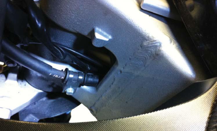
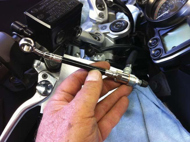
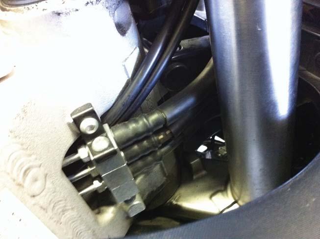
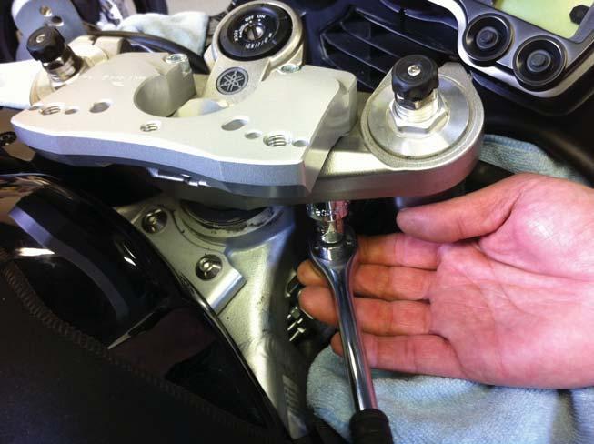
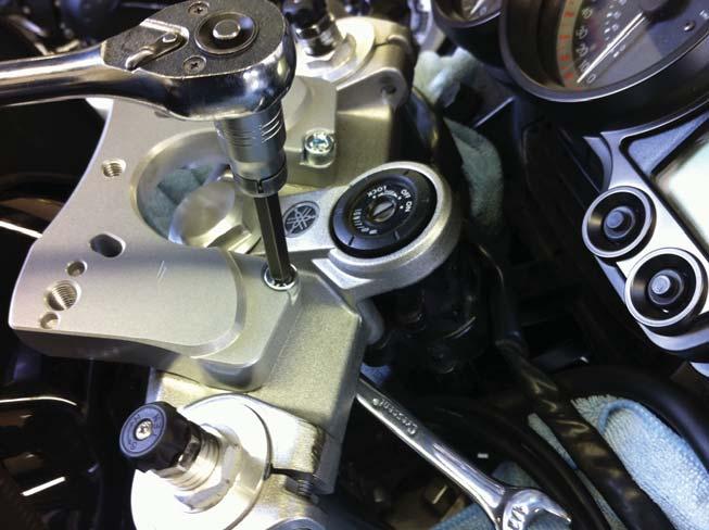
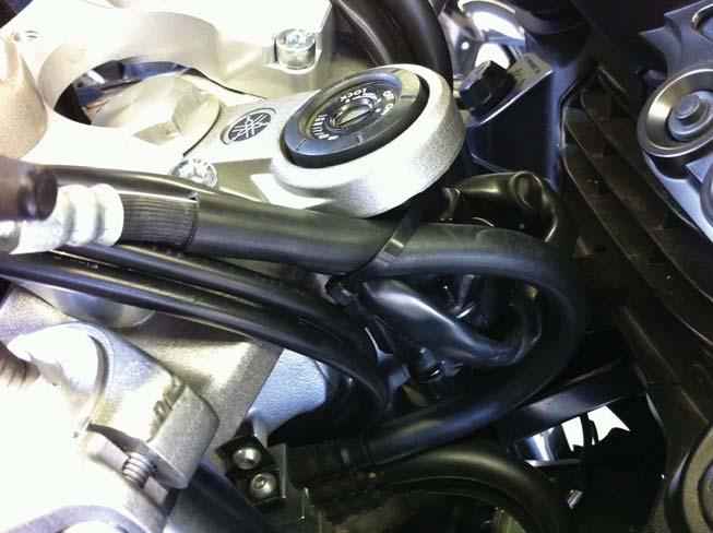
4 HeliBars Tour Performance Adjustable Handlebar Bridge Yamaha FJR1300 US & European Installation Instructions 1 Taller ~ 1 1/2-3 Rear Offset ~ 0-3 Wider IMPROPER INSTALLATION COULD RESULT IN SERIOUS INJURY OR DEATH. HAVE A QUALIFIED MECHANIC INSTALL YOUR HELIBARS. The Tour Performance adjustable handlebar bridge is intended to fit between the stock handlebars and the stock top triple clamp on all 2006 to 2013 FJR models. No additional aftermarket riser should be installed with the handlebar bridge as there will be no additional slack available in any of the cables and hydraulic line. Doing so could adversely effect it s safety and performance. The installation of the Tour Performance bridge requires several alterations to be performed prior to removing the handlebars from the stock triple clamp. 1.) Remove wire looms, cables and hydraulic lines from the metal stay in front of the top triple clamp. a. Cut the left and right side and remove cables, hydraulic lines and wire loom. ( Photo #1 & #2) b. Carefully cut the cable tie that gathers the right control housing wire loom with the ignition cable at the base of the ignition switch. Pull out the slack. (Photo #3) c. Remove the screw (8mm Head) that holds the clutch hydraulic line to the left side of the steering head, pry apart the P clip and remove from the line. (Photo #4 & #5) 2.) Install front brake hydraulic line extension. Leave reservoir cover on. a. Place shop rags on top of fuel tank and fairing top sides. b. Place a rag directly under the master cylinder. c. Loosen and remove hydraulic line banjo bolt from master cylinder. ( Photo #6 & #7) d. Place the bleeder banjo bolt provided into the banjo fitting of the stock line with a copper washer (supplied) on either side of the fitting as shown. (Photo #8) e. Hold the hydraulic extension as shown in ( Photo #9) with the banjo fitting angle facing up (on the left) and screw the bleeder banjo bolt into the AN3 fitting. Tighten. f. Fit the stock (black) banjo bolt through the line extension upper banjo fitting with a copper washer on either side and re-attach to the master cylinder. Tighten. (Photo #10) Tighten the lower AN3 fitting to the stock line with 14mm & 12mm wrenches firmly. Lightly tighten the bleeder fitting with an 8mm wrench. Page 4
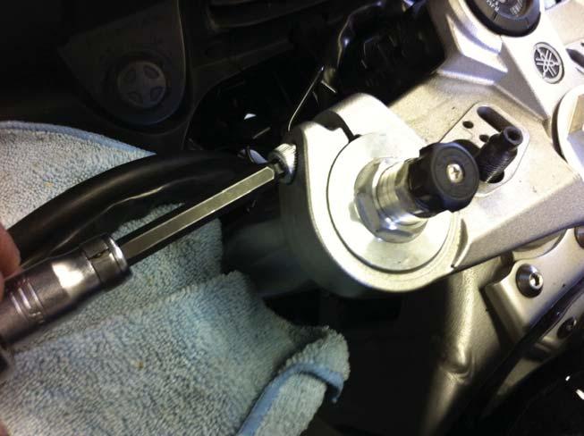
5 g. Remove the reservoir cover and bleed the master cylinder of air through the bleeder valve at the AN3 fitting. Lightly but quickly tap the brake lever to dislodge trapped air bubbles. Adjust fluid level by adding DOT 4 brake fluid if needed. Re-install the cover and wipe away brake fluid from master cylinder and fittings. Tighten bleeder and install black rubber cover. 3.) Reposition throttle cables to the inside of the hydraulic lines. a. Loosen and push the rubber boot down the throttle cables. ( Photo #11) b. Loosen and remove the two screws holding the two halves of the throttle housing together. ( Photo #12). Free the pull and push cables from the throttle sleeve, wind the cables down behind the fairing and bring them up the inside of the hydraulic lines. (Photo #13) Bring the cables up in front of the top triple clamp and re-assemble throttle housing. 4.) Gain additional slack from the left control housing wire loom. a. Locate the forward plastic cable strap and pop it out of it s mounting hole on the fairing frame. (Photo #15) DO NOT remove the rear most plastic strap from it s mount. Reach to the bottom of the rear strap, pull the small tab out while pushing up on the excess strap to loosen the pressure on the wire loom and pull the loom back towards the rider. 5.) Remove the stock handle bar mounting plate/cable guide. a. Remove the small cap head screws and covers at the stock handle bar base. ( Photo #15) b. Loosen and remove the L & R side M8 screws (6mm hex head). c. Loosen and remove the 17mm hex head nuts. Set the handlebars on rags on the sides of the fairing. d. Use a breaker bar and a 36mm socket to loosen the steering stem nut and remove it. NOTE: place a post-it over the stem nut before sliding the socket into place. This will eliminate scuffing and scratching the aluminum stem nut due to the high force required to loosen the nut. (Photo #16) e. Loosen the L & Right fork tube pinch bolts but do not remove. ( Photo #17) f. Remove the top triple clamp. Stand in front of the fairing. Put your thigh against the front wheel and push back, reach around the fairing and grab the triple clamp and push back and the clamp will slide off because you ve removed the bind that the machines weight puts on the steering stem. (Photo #18) Remove the factory bar mounting system. g. Re-install the triple clamp the same way you just removed it. Re-install the steering stem nut and lightly tighten. Torque the two fork tube pinch bolts to 14 ft. lbs. Now torque the steering stem nut to 85 ft. lbs. 6.) Install the Tour Performance adjustable handlebar bridge a. Hold the adapter as shown in ( Photo #19) and start on the M12 standard bolts with washer into it s threaded mounting hole through the bottom of the top triple clamp. Leave loose and install the second standard bolt with washer. Leave loose. b. Install both M8 x 35 socket head cap screws through the forward holes. ( Photo #20) Install the M8 washer and the nylon lock nuts and torque to 14 ft. lbs. (Photo #21) c. Torque 12mm bolts to 28 ft. lbs. (Photo #22) Page 5
6 7.) Re-install the handlebars onto the Tour Performance handlebar bridge adapter. ( Photo #23) a. Place the right side handlebar on the adapter and engage the two dowels into their receiving slots and start one of the M12 bolts (with threaded riser) with an M12 washer through the bar and thread it down but do not fully tighten. Leave it loose for now. Repeat this step on the left side. b. Install the two remaining M8 x 30 socket head caps and the standard nuts into position. ( Photo #24 & #25 for clarity) 8.) Adjust bars to a comfortable angle. There are two small index marks at the base of each handlebar where it mounts onto the adapter. They are located in front and will help mirror left and right side adjustments. After settling on an angle. Torque the two small handlebar mount M8 screws to 14 ft. lbs. Torque the two M12 bolts to 28 ft. lbs. a. Replace the handlebar hardware covers, install small button head cap screws and tighten. 9.) Cable tie wire looms and front brake hydraulic line a. On the right side of the machine put one of the cable ties provided around the front brake line, the right control housing wire loom and attach them to the right side of the ignition switch mount. (Photo #26) b. On the left side of the machine, use the 2nd cable tie to re-attach the right side control housing wire loom back to the ignition wire loom. Tighten tie and cut off excess. (Photo #27) 10.) Double check all work performed. Start machine outside, leave it in neutral and turn the handlebars all the way to the right steering stop then back all the way to the left steering stop. Make sure the machine remains at an idle. If the idle increases, re-adjust how the cables are positioned and refer to the photos.!! CAUTION!! BARS MUST BE TORQUED TO SPECIFIED VALUES. THEY MUST NOT BE OVERTORQUED. OVERTIGHTENED HARDWARE CAN LOSE INTEGRITY. For questions regarding installation please call HELI MODIFIED, INC ASSUMES NO LIABILITY FOR ANY INJURY OR LOSS OF PROPERTY WHICH MAY RESULT FROM IMPROPER INSTALLATION OR USE OF ANY HELIBARS. Page 6
7 Page 7


8 Photo # 1 Photo # 2 Photo # 3 Photo # 4 Page 8


9 Photo # 5 Photo # 6 Photo # 7 Photo # 8 Page 9


10 Photo # 9 Photo # 11 Photo # 10 Photo # 12 Page 10


11 Photo # 13 Photo # 15 Photo # 14 Photo # 16 Page 11


12 Photo # 17 Photo # 19 Photo # 18 Photo # 20 Page 12


13 Photo # 21 Photo # 23 Photo # 22 Photo # 24 Page 13


14 Photo # 25 Photo # 27 Photo # 26 Page 14
15 IMPORTANT INFORMATION ABOUT POWDER COATED HELIBARS HeliBars are finished with a polyester powder coating. The polyester is recommended for outdoor use because of it s excellent UV resistant quality; if we were to use an epoxy it would tend to fade and chalk pretty quickly when exposed to sunlight and UV rays. Care must be taken during installation because the finish can be scratched by the sharp surfaces of the controls and master cylinder clamps. When mounting the master cylinders to bars, do not let them move around the bars with the caps loose. Mount them in the proper position and hand tighten the screws until final adjustments are made; in this way you will lessen the possibility of scratching. NOTE: Powder coat finish is not indestructible, there are chemicals which may react negatively when applied to finish. Brake fluid may cause deterioration of the finish. We do not recommend the use of acetone or similar chemicals for cleaning purposes. We would recommend the use of an over-the-counter adhesive remover (such as Goo Gone) for the removal of any extraneous material. Please read labels directions for any cleaning/polishing product before use. If you have any questions regarding the use of any over-counter-products with the Heli- Bars, please call us before applying them to the powder coated finish. If care is taken during installation, your HeliBars will continue to look as good as when they were new. They will look great for years to come with a bit of wax and careful cleaning. Thank you for your purchase, ride safe and enjoy! Sincerely, Harry Eddy, President
16 Trailering with HeliBars HeliBars clip ons and handlebars must not be used as the primary holding points for tie downs while trailering. As with your stock bars applying extreme force to the ends of the bars can bend the bars or rotate them on their mounts. Use a wheel chock and pull the machine down and forward using soft ties or similar, attached to the lower triple clamp. Bars should only be used as secondary attachment points to steady the motorcycle from lateral sway. Failure to follow these guidelines can cause damage to the bars and the motorcycle, and may also void our warranty. Page 16
INSTALLATION INSTRUCTIONS
 INSTALLATION INSTRUCTIONS 2013-2014 Honda CBR500R/RA Tour Performance Handlebar Risers P/N: HR01087 IMPORTANT: PLEASE GIVE CUSTOMER ENCLOSED INFORMATION! Thank you for your purchase of our HeliBars. They
INSTALLATION INSTRUCTIONS
 INSTALLATION INSTRUCTIONS 2008-2013 Suzuki GSX1300R Hayabusa TracStar Replacment Handlebars P/N: TS03000 IMPORTANT: PLEASE GIVE CUSTOMER ENCLOSED INFORMATION! Thank you for your purchase of our HeliBars.
INSTALLATION INSTRUCTIONS
 INSTALLATION INSTRUCTIONS 2006-2008 BMW K1200R TracStar Handlebars P/N: TS05028 IMPORTANT: PLEASE GIVE CUSTOMER ENCLOSED INFORMATION! Thank you for your purchase of our HeliBars. They are designed to increase
INSTALLATION INSTRUCTIONS
 INSTALLATION INSTRUCTIONS 2004-2008 Ducati ST3/ST4 HeliBars Replacement Handlebar Risers P/N: HB2405 IMPORTANT: PLEASE GIVE CUSTOMER ENCLOSED INFORMATION! Thank you for your purchase of our HeliBars. They
INSTALLATION INSTRUCTIONS
 INSTALLATION INSTRUCTIONS BMW K1600GT/GTL 2011+ HeliBars Handlebar Relocation Adapters Part # HR05108 IMPORTANT: PLEASE GIVE CUSTOMER ENCLOSED INFORMATION! Thank you for your purchase of our HeliBars.
INSTALLATION INSTRUCTIONS
 INSTALLATION INSTRUCTIONS HeliBars Tour Performance Handlebar Riser 2014+ Yamaha Super Tenere P/N: HR09109 IMPORTANT: PLEASE GIVE CUSTOMER ENCLOSED INFORMATION! Thank you for your purchase of our HeliBars.
INSTALLATION INSTRUCTIONS
 INSTALLATION INSTRUCTIONS 1998-2008 R1 & 2008-2013 R6 TracStar Replacment Handlebars P/N: TS09073 IMPORTANT: PLEASE GIVE CUSTOMER ENCLOSED INFORMATION! Thank you for your purchase of our HeliBars. They
INSTALLATION INSTRUCTIONS. KAWASAKI Concours Handlebar Risers for ABS & Non-ABS Part # HR04042 & HR04042-NABS
 INSTALLATION INSTRUCTIONS KAWASAKI Concours14 2008-2015 Handlebar Risers for ABS & Non-ABS Part # HR04042 & HR04042-NABS IMPORTANT: PLEASE GIVE CUSTOMER ENCLOSED INFORMATION! Thank you for your purchase
INSTALLATION INSTRUCTIONS
 INSTALLATION INSTRUCTIONS BMW S1000RR 2015+ TracStar Replacement Handlebars P/N: TS05099 IMPORTANT: PLEASE GIVE CUSTOMER ENCLOSED INFORMATION! Thank you for your purchase of our HeliBars. They are designed
INSTALLATION INSTRUCTIONS
 INSTALLATION INSTRUCTIONS Horizon ST Patented Multi Axis Adjustable Handlebar System for 2012-2015 BMW K1600GTL P/N: HST05078 IMPORTANT: PLEASE GIVE CUSTOMER ENCLOSED INFORMATION! Patent No: US 8,230,758
INSTALLATION INSTRUCTIONS
 INSTALLATION INSTRUCTIONS 2005-2008 BMW K1200S TracStar Replacment Handlebars P/N: TS05027 IMPORTANT: PLEASE GIVE CUSTOMER ENCLOSED INFORMATION! Thank you for your purchase of our HeliBars. They are designed
INSTALLATION INSTRUCTIONS
 INSTALLATION INSTRUCTIONS 2006-2010 Kawasaki ZX10R TracStar Replacment Handlebars P/N: TS04072-KA 2011-2012 Kawasaki ZX10R TracStar Replacment Handlebars P/N: TS04072-KB IMPORTANT: PLEASE GIVE CUSTOMER
INSTALLATION INSTRUCTIONS
 INSTALLATION INSTRUCTIONS Ducati 749/999 TracStar TM HeliBars Replacement Handlebars P/N: TS07059 IMPORTANT: PLEASE GIVE CUSTOMER ENCLOSED INFORMATION! Thank you for your purchase of our HeliBars. They
INSTALLATION INSTRUCTIONS HONDA CBR250R P/N: HB01075
 INSTALLATION INSTRUCTIONS HONDA CBR250R P/N: HB01075 IMPORTANT: PLEASE GIVE CUSTOMER ENCLOSED INFORMATION! Thank you for your purchase of our HeliBars. They are designed to increase your long distance
INSTALLATION INSTRUCTIONS
 INSTALLATION INSTRUCTIONS 2017+ BMW R9T Racer HeliBars Replacement Triple Clamp w/built in Risers Part # HRT05126 IMPORTANT: PLEASE GIVE CUSTOMER ENCLOSED INFORMATION! Thank you for your purchase of our
INSTALLATION INSTRUCTIONS Horizon CCR HZ13054
 INSTALLATION INSTRUCTIONS Horizon CCR HZ13054 IMPORTANT: PLEASE GIVE CUSTOMER ENCLOSED INFORMATION! Thank you for your purchase of our HeliBars. They are designed to increase your long distance comfort
INSTALLATION INSTRUCTIONS Horizon XP Performance Handlebar
 INSTALLATION INSTRUCTIONS Horizon XP Performance Handlebar HZ10090XP, HZ10090XP-BA (1 Mount) Gen 1 HZ10093XP, HZ10093XP-BA (1 1/4 Mount) Gen 1 HZ10096XP, HZ10096XP-BA ( 1 1/4 Mount) Gen 2 HZ10097XP, HZ10097XP-BA
Horizon LST Installation Photos Honda GL F6B Bagger P/N: LST01084
 Horizon LST Installation Photos 2001-2015 Honda GL1800 2013-2015 F6B Bagger P/N: LST01084 IMPORTANT: PLEASE GIVE CUSTOMER ENCLOSED INFORMATION! Thank you for your HeliBars purchase. HeliBars are designed
2010 BMW S1000RR TracStar HeliBars TS mm taller (1.7 ) ~ 20mm Rear Offset (.8 ) ~ Stock Width (25 ¼ )
 ~ 20mm Rear Offset (.8 ) ~ Stock Width (25 ¼ )") WARNING: IMPROPER INSTALLATION COULD RESULT IN SERIOUS INJURY OR DEATH. HAVE A QUALIFIED MECHANIC INSTALL YOUR HELIBARS. Right Side To protect your motorcycle during installation place clean shop rags
WARNING: IMPROPER INSTALLATION COULD RESULT IN SERIOUS INJURY OR DEATH. HAVE A QUALIFIED MECHANIC INSTALL YOUR HELIBARS. Right Side To protect your motorcycle during installation place clean shop rags
INSTALLATION INSTRUCTIONS FOR THE MOTOR TRIKE CROSS COUNTRY / CROSS ROADS / HARD BALL RAKE KIT
 INSTALLATION INSTRUCTIONS FOR THE MOTOR TRIKE CROSS COUNTRY / CROSS ROADS / HARD BALL RAKE KIT Thank you for choosing the Motor Trike Cross Country / Cross Roads / Hard Ball rake kit. We ask that you read
w w w. h d o n l i n e s h o p. d e STREET SLAMMER HANDLEBAR KIT GENERAL INSTALLATION -J03363 REV Kit Number Models Kit Contents
 -J06 REV. 006-06- GENERAL Kit Number 69-0 Models STREET SLAMMER HANDLEBAR KIT Ask a Harley-Davidson dealer or refer to the latest Harley- Davidson Genuine Motor Accessories and Genuine Motor Parts catalog
Superbike Kit
 Superbike Kit www.spieglerusa.com sales@spieglerusa.com Mounting Instructions & Safety Instructions for Honda CBR 1000 RR ABS model year 2017 - Attention Important Safety Instructions: Thank you for purchasing
Be sure to read and go over all pages before you start your installation
 Yamaha Gen-2 V-MaxV Holeshot Superbike Bars Installation Guide Pre-Installation Note Be sure to read and go over all pages before you start your installation Preparation for Installation A) It is recommended
Replacing a Brake Line by UCLA-Vstar, April 2007
 Replacing a Brake Line by UCLA-Vstar, April 2007 Replacing a brake line may seem intimidating if you ve never bled brakes before, and especially if you cannot find a stepby-step how-to. Here s a crude
w w w. h d o n l i n e s h o p. d e CRUISE CONTROL KIT GENERAL INSTALLATION -J04064 REV Kit Number Models Additional Parts Required
 -J006 REV. 006-08- CRUISE CONTROL KIT GENERAL Kit Number 7796-07 Models For the most up-to-date model fitment information, please see the product label or www.harley-davidson.com. Additional Parts Required.
INSTALLATION TURN SIGNAL MIRRORS 1432
 1432 PARTS INCLUDED 1 Left Side Turn Signal Mirror Assembly with Convex Glass 1 Right Side Turn Signal Mirror Assembly with Convex Glass 1 Hardware Kit, Including: 2 5/16-18 X 1-1/2 Socket Head Cap Screws
2. Remove front wheels.
 1 PARTS DIAGRAM 2 Installation Instructions: (PASSENGER SIDE) 1. Place jack under center of RUV front end and lift until front wheels clear the ground. Be careful to support the RUV properly so that it
INSTALLATION PROCESS: FK003D945-7 Complete Front, Rear, and Clutch A.B.S. KIT Harley Davidson FLH Touring Models
 INSTALLATION PROCESS: FK003D945-7 Complete Front, Rear, and Clutch A.B.S. KIT 2014-2017 Harley Davidson FLH Touring Models Parts List: 4 Lines 1 Brake Light Switch Adapter 7 Single banjo bolts 2 Caliper
Assembly Instructions
 www.rockymounts.com TandemMount R4 Installation Manual Guidelines/Restrictions: - This carrier is intended for Thule rectangular and Yakima round bars only. - Bicycles must be equipped with quick release
BrakeAway Products Inc. wishes you many years of cramp free cruising, ENJOY and ride SAFELY!!!
 Congratulations on the purchase of your new BrakeAway Motorcycle Cruise Control. At BrakeAway Products, we are committed to your complete satisfaction. With proper installation, use, and periodic maintenance,
w w w. h d o n l i n e s h o p. d e MODULAR DIAMONDBACK BRAKE LINE KITS GENERAL -J04284 REV Kit Number Models Tools and Supplies Required
 -J08 REV. 007-07-6 GENERAL MODULAR DIAMONDBACK BRAKE LINE KITS Table. Upper Brake Line s (Banjo Angle 0 - Straight) 7-07 77-07 79-07 8-07 87-07 9-07 8-07 8 inch 9 inch 0 inch inch inch inch inch 96-07
w w w. h d o n l i n e s h o p. d e ROAD KING FAT HANDLEBAR KIT GENERAL PREPARATION - ALL MODELS -J02375 REV Kit Number Models ABS Models
 -J02375 REV. 2008--9 GENERAL Kit Number 56675-05 Models For model fitment information, see the P&A Retail Catalog or the Parts and Accessories section of www.harley-davidson.com (English only). ABS Models
INSTALLATION GUIDE. RMS510, 511, 512, 513, 511MC 510-OR, 512-OR Manual Revision:
 REKLUSE MOTOR SPORTS z-start Dual-Actuated Brake Kit INSTALLATION GUIDE RMS510, 511, 512, 513, 511MC 510-OR, 512-OR 196-210 Manual Revision: 051309 2002-2009 Rekluse Motor Sports Rekluse Motor Sports,
P/N Instr Rev Page 1 of 11
 BRAKE AND CLUTCH KIT P/N 2883864 IMPORTANT Due to the technical nature of this kit, Indian Motorcycle insists this installation be performed by a certified Indian Motorcycle Technician. APPLICATION Verify
I N S TA L L AT I O N
 I N S TA L L AT I O N 5008 fits: H-D: '80-Up Electra glide, tour glide, road king, road glide or street glide PartS Included 1 Right Fork Mount Assembly 1 Left Fork Mount Assembly 2 H3 Driving Light Assemblies
Please contact BrakeAway Products tech support for additional (503) or
 or") Congratulations on the purchase of your new BrakeAway Motorcycle Cruise Control. At BrakeAway Products, we are committed to your complete satisfaction. With proper installation, use, and periodic maintenance,
Congratulations on the purchase of your new BrakeAway Motorcycle Cruise Control. At BrakeAway Products, we are committed to your complete satisfaction. With proper installation, use, and periodic maintenance,
Service & Bleed Guide
 Service & Bleed Guide Hayes Performance Systems 5800 W. Donges Bay Rd. Mequon, WI 53092 Tel: 888.686.3472 Email: techsupport@hayesbicycle.com Web: www.hayescomponents.com Hayes Components Europe Dirnismaning
INSTALLATION HYPERCHARGER AIR FILTER KIT 9754
 9754 PARTS INCLUDED 1 Chrome Hypercharger Assembly 1 Support Bracket 1 Breather Hardware Kit, including: 2 1-1/4 Breather Bolts 2 Breather Hoses 4 Shim Washers 1 Twin Cam Breather Kit, Including: 1 Breather
INSTALLATION HYPERCHARGER AIR FILTER KIT 9992
 9992 PARTS INCLUDED 1 Chrome Hypercharger Assembly with Chrome Blood Groove Trap Door and Chrome Butterflies 1 Support Bracket 1 Breather Hardware Kit, including: 2 1-1/4 Breather Bolts 2 Breather Hoses
INSTALLATION CONSTELLATION DRIVING LIGHTS 5009
 INSTALLATION CONSTELLATION DRIVING LIGHTS 5009 PARTS INCLUDED 1 Right Driving Light with Turn Signals 1 Left Driving Light with Turn Signals 1 Installation Component Kit Including: 8 Insulated Male Spades
DISC BRAKE/DUAL MASTER CYLINDER CONVERSION. Tools, Equipment and Supplies Needed:
 Please take the time to read the enclosed instructions carefully. If you have any questions, call our Product Assistance personnel for clarification. It is important to note that these instructions contain
INSTALLATION CONSTELLATION DRIVING LIGHTS 5009
 INSTALLATION CONSTELLATION DRIVING LIGHTS 5009 PARTS INCLUDED 1 Right Driving Light with Turn Signals 1 Left Driving Light with Turn Signals 1 Installation Component Kit Including: 8 Insulated Male Spades
w w w. h d o n l i n e s h o p. d e DETACHABLE WINDSHIELD AND DOCKING HARDWARE KIT GENERAL INSTALLATION -J00325 REV Kit Number Models
 -J00 REV. 00-- DETACHABLE WINDSHIELD AND DOCKING HARDWARE KIT GENERAL Kit Number -A, 0-, -, 0-, -, - 0, -0 Models These kits fit and later FXST, FXSTB, FXSTC, and and later FXDWG Harley-Davidson model
w w w. h d o n l i n e s h o p. d e CHROME FRONT BRAKE MASTER CYLINDER KIT GENERAL INSTALLATION -J03735 REV Kit Number Models
 -J05 REV. 005-06- GENERAL Kit Number 58-D, 58-D Models CHROME FRONT BRAKE MASTER CYLINDER KIT These Chrome Master Cylinder Kits are designed to replace the original equipment front brake master cylinder
VW/AUDI MK7 VEHICLES
 Installation Manual P/N 1-301-1708-01 (STAGE 2+ FUEL KIT) P/N 1-301-1708-02 (STAGE 3+ FUEL KIT) VW/AUDI MK7 VEHICLES Warning: This installation is not recommended for a novice or the new guy in the shop.
INSTALLATION GUIDE. RMS500, RMS501, RMS502, RMS503, RMS506, RMS507, RMS508, RMS509, -OR Manual Revision:
 REKLUSE MOTOR SPORTS z-start Brake Kit INSTALLATION GUIDE RMS500, RMS501, RMS502, RMS503, RMS506, RMS507, RMS508, RMS509, -OR 196-200 Manual Revision: 051309 2009 Rekluse Motor Sports Rekluse Motor Sports,
Multistrada (MTS) Tank Installation Notes. Tools Required. Phase 1: Remove Fairings. Phase 2: Remove Fuel Tank
 Tank Installation Notes. Tools Required. Phase 1: Remove Fairings. Phase 2: Remove Fuel Tank") The California Cycleworks MTS tank provides an aftermarket alternative to the OEM nylon fuel tanks as used on aircooled Desmodue Ducati Multistrada 1100, 1000, and 620 models. This fuel tank is NOT for
The California Cycleworks MTS tank provides an aftermarket alternative to the OEM nylon fuel tanks as used on aircooled Desmodue Ducati Multistrada 1100, 1000, and 620 models. This fuel tank is NOT for
INSTALLATION GUIDE DIRECT-REPLACEMENT
 DIRECT-REPLACEMENT INSTALLATION GUIDE TUNDRA (07+) 985-02-004: 2.0 Performacne Series Coil-over IFP 883-02-021: 2.5 Factory Series Coil-over IFP 880-02-367: 2.5 Factory Series Coil-over Reservoir 880-06-367:
INSTALLATION INSTRUCTIONS
 THANK YOU FOR CHOOSING KURYAKYN! Protect yourself and others from possible injury and property damage or loss. Pay close attention to all instructions, warnings, cautions, and notices regarding the installation,
Torque specifications Stainless steel ft. lbs Aluminum ft. lbs
 INSTALLATION PROCESS: FK003D738C Front and Rear Brake Line Kit 2009-2012 BMW S1000 RR ABS Torque specifications Stainless steel 15-17 ft. lbs Aluminum 12-15 ft. lbs Step 1: Identify the key components
INSTALLATION FORK MOUNTED DRIVING LIGHTS 5008
 5008 PARTS INCLUDED 1 Right Fork Mount Assembly 1 Left Fork Mount Assembly 2 H3 Driving Light Assemblies 1 12-Pin Wiring Adapter 1 Hardware Kit for Fork Mount Driving Lights, Including: 6 5/16-18 Nylock
INSTALLATION INSTRUCTION Rev A
 INSTALLATION INSTRUCTION 88587 Rev A FOR RANCHO SUSPENSION SYSTEM RS6587B: 2009 DODGE RAM 1500 READ ALL INSTRUCTIONS THOROUGHLY FROM START TO FINISH BEFORE BEGINNING INSTALLATION IMPORTANT NOTES! WARNING:
INSTALLATION. Note: Not all parts will be used in the installation of this product. -cont.-
 5005 Fits: 06-up FLHX, 04-up Screamin Eagle Ultra Classic Electra Glide & Screamin Eagle Electra Glide Classic, '97-up FLHT, FLHTC, FLHTCU, FLHR PartS Included 1 Right Driving Light Assembly 1 Left Driving
w w w. h d o n l i n e s h o p. d e CHROME 1.25 INCH (31.75 MM) DIAMETER HANDLEBAR KIT GENERAL INSTALLATION -J04405 REV Kit Number Models
 DIAMETER HANDLEBAR KIT GENERAL INSTALLATION -J04405 REV Kit Number Models") -J005 REV. 008-09-0 CHROME.5 INCH (.75 MM) DIAMETER HANDLEBAR KIT GENERAL Kit Number 560-08 Models For model fitment information, see the P&A retail catalog or the Parts and Accessories section of www.harley-davidson.com
-J005 REV. 008-09-0 CHROME.5 INCH (.75 MM) DIAMETER HANDLEBAR KIT GENERAL Kit Number 560-08 Models For model fitment information, see the P&A retail catalog or the Parts and Accessories section of www.harley-davidson.com
JEEP CHEROKEE (ZJ) 2 POLY SPACER KIT KIT# TM & TM
 2 POLY SPACER KIT KIT# TM & TM") 400 W. Artesia Blvd. Fax: (310) 747-3912 Compton, CA 90220 Ph: (877) 695-7812 www.trailmastersuspension.com JEEP CHEROKEE (ZJ) 2 POLY SPACER KIT 93-98 KIT# TM3820-40010 & TM3820-40013 Installation of a
400 W. Artesia Blvd. Fax: (310) 747-3912 Compton, CA 90220 Ph: (877) 695-7812 www.trailmastersuspension.com JEEP CHEROKEE (ZJ) 2 POLY SPACER KIT 93-98 KIT# TM3820-40010 & TM3820-40013 Installation of a
AmTryke Adult Recumbent Model JT2000 #50-FC-2000
 AmTryke Adult Recumbent Model JT2000 #50-FC-2000 TOOLS Needed for Assembly 5 mm Allen Wrench 8 mm Socket or Wrench 10 mm Socket or Wrench 14 mm Socket or Wrench 15 mm Socket or Wrench 22 mm Socket or Adjustable
CHAINGUARD REGAL ST COLOR
 DESOTO/ REGAL HAULER PARTS LIST Item Part # Description QTY Item Part # Description QTY 1 11871 REFLECTOR KIT TRIKE 1 32 11764 FENDER BRACE 24" MWT 1 2 12199 SCREW #14 x 3/4 4 33 12176 NUT5/16-24 HEX 2
RANGER WD/4WD KIT PACKING SLIP
 RANGER +2.5 2WD/4WD KIT PACKING SLIP DYNAMICS Thank you for puchasing our long travel kit. We pride ourselves on designing and fabricating our parts in our shop located in Las Vegas, Nevada. If you have
INSTALLATION & USER S GUIDE
 REKLUSE MOTOR SPORTS The Rekluse Core EXP Kit with Adjustable Slave Cylinder INSTALLATION & USER S GUIDE Doc ID: 191-7704A Doc Rev: 102915 OVERVIEW This kit replaces the OEM core clutch components including
Installation Manual TWM Performance Short Shifter Cobalt SS/SC, SS/TC, HHR SS, Ion Redline and Saab 9-3
 Page 1 Installation Manual TWM Performance Short Shifter Cobalt SS/SC, SS/TC, HHR SS, Ion Redline and Saab 9-3 Please Note: It is preferable to park on a flat surface, as you will have to engage and disengage
Installation manual. Toyota Tundra 4WD & 2WD. 2.5 Suspension kit. Part # Part # Important customer information:
 Installation manual 2007-2016 Toyota Tundra 4WD & 2WD 2.5 Suspension kit Part # 53070 sj11082011rev.03 Part # 53070 2007-2016 Toyota Tundra 4WD & 2WD 2.5 Suspension kit Part # Description Qty. 53070-01
INSTALLATION BLIND SPOT TURN SIGNAL MIRRORS 1457
 BLIND SPOT TURN SIGNAL MIRRORS 1457 PARTS INCLUDED 2 Blind Spot Turn Signal Mirror Assemblies 1 Wire Harness Kit Including: 2 Wiring Harness (four pin) 1 Adapter Harness (six pin) 2 3-Pin Female Connectors
V-Twin Forward Control Installation Instructions
 V-Twin Forward Control Installation Instructions Thank you for a choosing a Supreme Legends USA product. Supreme Legends forward controls are designed to add style and performance to your bike. Our extended
Yamaha Nytro Relocator Kit
 Included Parts: 1 Relocator bracket assembly 2 Upper assembly Oilite bushing halves 1 Lower steering block assembly 2 Lower assembly Oilite bushing halves 1 Tube of Loc-tite OFTRacing.com Email Scott Moto
CHAINGUARD REGAL ST COLOR
 DESOTO/ REGAL HAULER PARTS LIST Item Part # Description QTY Item Part # Description QTY 1 11871 REFLECTOR KIT TRIKE 1 32 11762 FENDER BRACE 20" MWT 1 2 12199 SCREW #14 x 3/4 4 11764 FENDER BRACE 24" MWT
Tools, Equipment and Supplies Needed:
 153-162 DISC BRAKE/DUAL MASTER CYLINDER CONVERSION Please take the time to read the enclosed instructions carefully. If you have any questions, call our Product Assistance personnel for clarifi cation.
INSTALLATION. led fairing lights for gl
 for gl1800 4627 Fits: 01-up GL1800 Parts Included 4 7-Color Lizard Lights 1 7-Color Controller/Switch 1 Hardware Kit including: 4 Replacement Adhesive Pads 4 18 Extensions 1 Double Male Lizard Light Connector
w w w. h d o n l i n e s h o p. d e HEATED HAND GRIP KITS GENERAL REMOVAL -J02983 REV Kit Number Models Kit numbers Service Parts
 -J098 REV. 007-0-0 GENERAL Kit Number 56047-0B, 5607-0B, 5674-0B, 5696-0B, 565-0B, 5669-0A, 56694-04A, 56750-04A, 5688-0A, 569-05, 5696-05, 56997-07 Models For model fitment information, please see the
w w w. h d o n l i n e s h o p. d e DETACHABLE WINDSHIELD KITS GENERAL INSTALLATION -J04501 REV Kit Number Models Kit Contents
 -J00 REV. 007-06-0 GENERAL Kit Number 88-08 and 788-08 Models For model fitment information, please see the P&A Retail Catalog or the Parts and Accessories section of www.harleydavidson.com (English only).
INSTALLATION INSTRUCTION 88581
 INSTALLATION INSTRUCTION 88581 FOR RANCHO SUSPENSION SYSTEM RS6581B: DODGE RAM READ ALL INSTRUCTIONS THOROUGHLY FROM START TO FINISH BEFORE BEGINNING INSTALLATION Rev C IMPORTANT NOTES! WARNING: This suspension
INSTALLATION CLAMP-ON FORK MOUNTED DRIVING LIGHTS 5015
 CLAMP-ON 5015 PARTS INCLUDED 2 Driving Lights 2 Side Mount Clamps-43mm/49mm 1 Hardware Kit Including: 2 49mm Spacers 4 43mm Spacers 2 Pivot Dome Washers 2 3/8-16 Serrated Hex Nut 1 Wiring Kit for Driving
SOS LOWERING KIT INSTALLATION MANUAL Leaf Spring Shackle and Hardware
 Page 12 PARTS INCLUDED IN KIT Front Coil Spring Perch, Sleeve and Bump Stops SOS LOWERING KIT INSTALLATION MANUAL Leaf Spring Shackle and Hardware SOS 2050 Axle Perches Bottom Plates APPLICATIONS 2007
04 & 14 F FRONT 1.0 REAR LEVELING KIT INSTALLATION
 INSTRUCTION PART NO 15312 KIT NO 3836 04 & 14 F-150 2.0 FRONT 1.0 REAR LEVELING KIT INSTALLATION READ INSTRUCTIONS COMPLETELY THROUGH BEFORE STARTING. FAILURE TO ADHERE TO THE INSTRUCTIONS WILL VOID ANY
Table of Contents Safety Warning Information
 SUSPENSION FORK INSTRUCTION MANUAL 2 Table of Contents 04... Safety Warning Information 05... Tools Needed 06... Fork Features Overview 07... Crown Race Installation/Steer Tube Cutting 08... Star Nut/Stem
INSTALLATION INSTRUCTIONS
 Equipped with AEM Dryflow Filter No Oil Required! INSTALLATION INSTRUCTIONS PART NUMBER AEM-21-805C (GUN METAL GRAY FINISH) 2016.5-19 CHEVROLET CRUZE 1.4T 1 ITEM NO. PART NUMBER DESCRIPTION QTY. 1 21-2038DK
DETACHABLE QUARTER FAIRING AND DOCKING HARDWARE KIT
 INSTRUCTIONS -J09 REV. 0--00 Kit Numbers 7070-98 (primed kit) DETACHABLE QUARTER FAIRING AND DOCKING HARDWARE KIT General This kit is for installation on 988 and later XL, FXR and FXD model motorcycles
INSTALLATION GUIDE DIRECT-REPLACEMENT
 DIRECT-REPLACEMENT INSTALLATION GUIDE TACOMA (05+) 880-06-376-2.5 Factory Series Coil-Over Reservoir - Adjustable 880-06-418-2.5 Factory Series Coil-Over Reservoir - Adjustable 880-02-376-2.5 Factory Series
w w w. h d o n l i n e s h o p. d e CHROME SWITCH HOUSING KIT GENERAL HANDLEBAR SWITCH REMOVAL/INSTALLATION FXDWGI AND FXDBI MODEL TURN SIGNAL REMOVAL
 -J00 REV. 00-07-9 GENERAL Kit Number 70-9B, 70-9B, 708-9C Models For the most up-to-date model fitment information, please see the product label or www.harley-davidson.com. See Table for items contained
Avoid damage to the motorcycle. Protect painted surfaces with a soft cloth or blanket.
 HOUSINGS 7808 Thank You For Choosing Küryakyn! Protect yourself and others from potential injury and property damage or loss. Pay close attention to all instructions, warnings, cautions, and notices regarding
Trike Conversion Installation Guide for Harley-Davidson Sportster Motorcycles 2004 & Up Revision 7
 Trike Conversion Installation Guide for Harley-Davidson Sportster Motorcycles 2004 & Up Revision 7 CAUTION : Failure to follow these instructions can lead to serious personal injury and/or property damage
JEEP WRANGLER 2 & 4 DOOR (JK) 2.5 SPACER KIT KIT# TM /TM
 2.5 SPACER KIT KIT# TM /TM") 400 W. Artesia Blvd. Fax: (310) 747-3912 Compton, CA 90220 Ph: (877) 695-7812 www.trailmastersuspension.com JEEP WRANGLER 2 & 4 DOOR (JK) 2.5 SPACER KIT 07-13 KIT# TM3325-40010/TM3325-40013 Installation
400 W. Artesia Blvd. Fax: (310) 747-3912 Compton, CA 90220 Ph: (877) 695-7812 www.trailmastersuspension.com JEEP WRANGLER 2 & 4 DOOR (JK) 2.5 SPACER KIT 07-13 KIT# TM3325-40010/TM3325-40013 Installation
CLASSIC WINDSHIELD SUPPLEMENTAL INSTRUCTIONS FOR HONDA VTX (2002- )
") http://www.rifle.com CLASSIC WINDSHIELD SUPPLEMENTAL INSTRUCTIONS FOR HONDA VTX (2002- ) 1.) Loosen turnsignals and slide them up forks to a position where center of turnsignal stem is approx. 3-1/2 above
http://www.rifle.com CLASSIC WINDSHIELD SUPPLEMENTAL INSTRUCTIONS FOR HONDA VTX (2002- ) 1.) Loosen turnsignals and slide them up forks to a position where center of turnsignal stem is approx. 3-1/2 above
INSTALLATION. DRIVING LIGHTS for FLHT/FLHX/FLHR 5005
 DRIVING LIGHTS for FLHT/FLHX/FLHR 5005 PARTS INCLUDED 1 Right Driving Light Assembly 1 Left Driving Light Assembly 1 Right Driving Light Bracket 1 Left Driving Light Bracket 4 Driving Light Bracket Plugs
INSTRUCTIONS. w w w. h d o n l i n e s h o p. d e SPRINGER AUXILIARY LAMP KIT 1WARNING -J03497 REV General.
 INSTRUCTIONS -J097 REV. 0-0-00 Kit Number 6986-0A General Auxiliary/fog lamps are not included in this kit. The lamps must be purchased separately. HDI (International) motorcycles should only use approved
SCION tc BIG BRAKE KIT Section I - Installation Preparation
 SCION tc 2005- BIG BRAKE KIT Section I - Installation Preparation Part Number: PTR09-21080 Kit Contents Item # Quantity Reqd. Description 1 1 Brake Rotor, LH Front 2 1 Brake Rotor, RH Front 3 1 Brake Caliper
Installation & Set-Up Instructions
 Installation & Set-Up Instructions Hayes Performance Systems 5800 W. Donges Bay Rd. Mequon, WI 53092 Tel: 888.686.3472 Email: techsupport@hayesbicycle.com Web: www.hayescomponents.com Hayes Components
Raider/Roadliner/Stratoliner Forward Control Installation Instructions
 Raider/Roadliner/Stratoliner Forward Control Installation Instructions Thank you for a choosing a Supreme Legends USA product. Supreme Legends adjustable forward controls are designed to give riders a
Installation manual. 2 Suspension System. Ford F150 4WD and 2WD. Part # Part # Ford F150 4WD and 2WD
 Installation manual 2 Suspension System 2009-2018 Ford F150 4WD and 2WD Part # 22929 sj12112013rev.03 Part # 22929 2009-2018 Ford F150 4WD and 2WD 2 Suspension System Part # Description Qty. 22909-01 Front
INSTALLATION GUIDE. Doc ID: A Doc Rev:
 REKLUSE MOTOR SPORTS EXP Kit for Harley-Davidson Big Twin Hydraulic-Actuated OVERVIEW INSTALLATION GUIDE Doc ID: 191-6200A Doc Rev: 061215 This kit replaces the OEM clutch pack (friction disks and drive
INSTALLATION AIRMASTER DELUXE FAIRING 1335
 AIRMASTER DELUXE FAIRING 1335 PARTS INCLUDED 1 Airmaster Fairing 1 Dragon Wing Spacer kit 1 Light Bar Relocation Hardware Kit 2 1/2" Spacers 2 1" Spacers 6 5/16"-24 x 1" Button Head Cap Screw, Chrome 4
INSTALLATION INSTRUCTIONS
 Equipped with AEM Dryflow Filter No Oil Required! INSTALLATION INSTRUCTIONS PART NUMBER: 21-8029 2011-2010 CHEVROLET Camaro V8-6.2L SEE * NOTE * NOTE: Legal in California only for racing vehicles which
INSTALLATION GUIDE CRF150R Manual Revision:
 REKLUSE MOTOR SPORTS The z-start Pro Clutch INSTALLATION GUIDE CRF150R 191-810 Manual Revision: 032508 2002 Rekluse Motor Sports Rekluse Motor Sports, Inc. 110 E. 43rd Street Boise, Idaho 83714 208-426-0659
INSTALLATION INSTRUCTIONS
 Equipped with AEM Dryflow Filter No Oil Required! INSTALLATION INSTRUCTIONS PART NUMBER: 21-8028 2010 CHEVROLET Camaro V6-3.6L SEE * NOTE * NOTE: Legal in California only for racing vehicles which may
12. FRONT WHEEL/FRONT BRAKE/
 12 4.5kgm 0.9kg-m 4.5kg-m 12-0 SERVICE INFORMATION... 12-1 HYDRAULIC BRAKE... 12-10 TROUBLESHOOTING... 12-2 FRONT SHOCK ABSORBER... 12-16 FRONT WHEEL... 12-3 STEERING HANDLEBAR... 12-19 FRONT BRAKE...
NOTE: IF RUNNING FACTORY RANGER ALUMINUM WHEELS OR AFTERMARKET ALUMINUM WHEELS THEN SPACERS ARE NOT REQUIRED.
 780 Professional Dr. North, Shreveport, LA. 318-524-2270 Polaris Ranger Lift Kit Installation Instructions PLK1000R-51 Read before Installation This product is designed for use on ATVs and/or RUVs to increase
 .1..2..3..4..5..6..7..8..9..10. MANITOU SUSPENSION FORKS CONGRATULATIONS ON CHOOSING A 2003 MANITOU SIX FORK. This Manitou SIX fork is fully assembled and ready to be installed onto your bicycle. It comes
INSTALLATION GUIDE DIRECT-REPLACEMENT
 DIRECT-REPLACEMENT INSTALLATION GUIDE FJ CRUISER (10+) 4RUNNER (10+) 883-06-111-2.5 Factory Series Coil-Over Reservoir - Adjustable 883-02-111-2.5 Factory Series Coil-Over Reservoir 880-02-361-2.5 Factory
Installation manual 3 suspension system Toyota Tacoma 4 x 4 & PreRunner Part # sj rev.03
 Part #: 52904 1995-2004 Toyota Tacoma 4 x 4 & PreRunner 3 suspension system Parts list: Part # Description Qty. 52904-01 Rear brake proportioning valve bracket 1 52907-02 Front pre load spacer 2 52904-03
Low Range HD 2 Inch Body Lift Kit (Sidekick, GV, Vitara, Tracker, X90) SKU# KSP-BL2
 SKU# KSP-BL2") Low Range HD 2 Inch Body Lift Kit (Sidekick, GV, Vitara, Tracker, X90) SKU# KSP-BL2 Installation Instructions Background: These instructions are designed for installing the 2 body lift. They can also be
Low Range HD 2 Inch Body Lift Kit (Sidekick, GV, Vitara, Tracker, X90) SKU# KSP-BL2 Installation Instructions Background: These instructions are designed for installing the 2 body lift. They can also be
Mopar 8 3/4 & 9 3/4 (Dana) Installation Instructions Rear Disc Conversion
 Installation Instructions Rear Disc Conversion") Mopar 8 3/4 & 9 3/4 (Dana) Installation Instructions Rear Disc Conversion This kit is for either Mopar 8 ¾ or Mopar 9 ¾ (Dana). This kit is designed to work with axles with either GM 5 x 4.75 Bolt Pattern
Mopar 8 3/4 & 9 3/4 (Dana) Installation Instructions Rear Disc Conversion This kit is for either Mopar 8 ¾ or Mopar 9 ¾ (Dana). This kit is designed to work with axles with either GM 5 x 4.75 Bolt Pattern