TR50/60/70/75-SR50/60/75. Repair Manual. General Pump is a member of the Interpump Group. Ref Rev.A 05-15
|
|
|
- Clare Burke
- 5 years ago
- Views:
Transcription


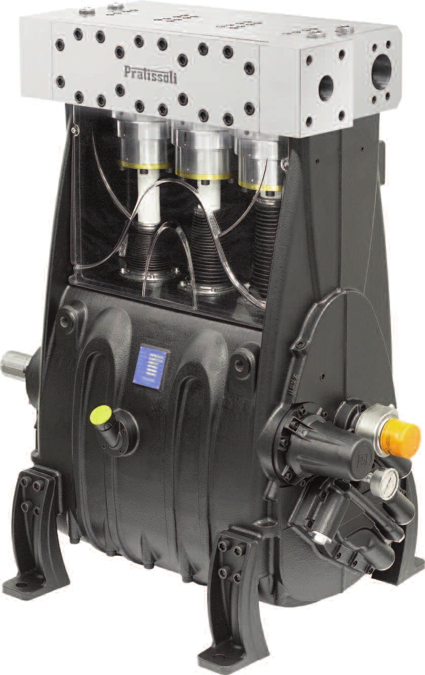

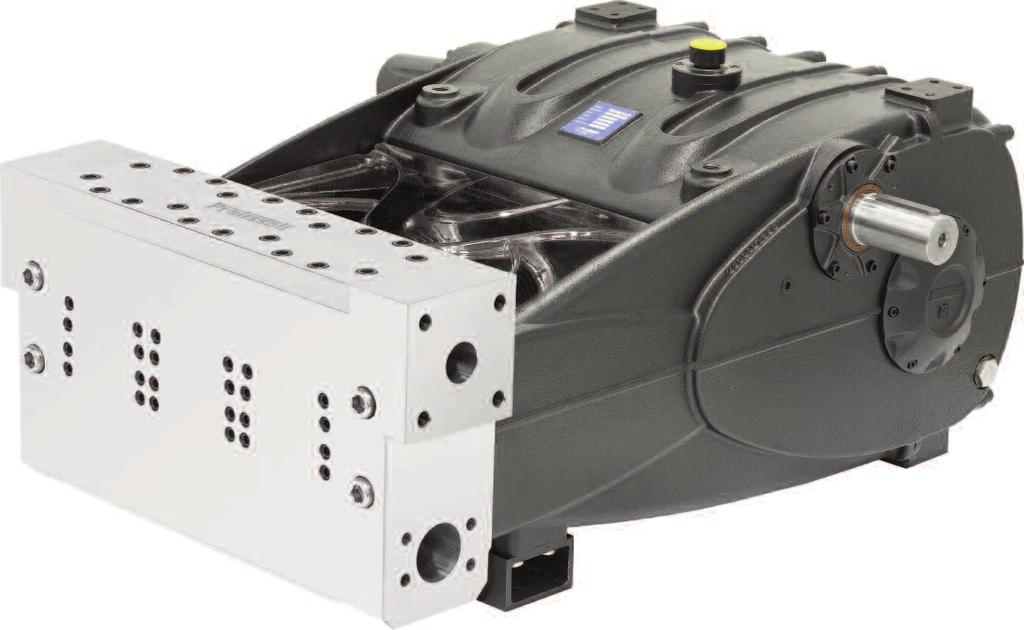
1 TR50/60/70/75-SR50/60/75 Repair Manual 8 General Pump is a member of the Interpump Group
2 GENERAL PUMP A member of the Interpump Group TR50/60/70/75-SR50/65/75 SERIES INDEX 1. INTRODUCTION Page 3 2. REPAIR INSTRUCTIONS Page Repairing Mechanical Parts Page Disassembly of Mechanical Parts Page Removing the lube pump page Reassembly of Mechanical Parts Page Fitting the lube pump page Removing the bellows - vertical versions page 26 Fitting the bellows - vertical versions page Oversize classes page Repairing Hydraulic Parts Page Dismantling the manifold in horizontal versions-valve inserts......page Assembling the manifold - valve inserts page Dismantling the piston unit - supports - seals page Assembling the piston unit - supports - seals page SCREW CALIBRATION Page REPAIR TOOLS Page REPLACING THE CON-ROD SMALL END BUSHING Page MAINTENANCE LOG Page 44 Page 2


 M6 fixing screws of the three oil seal covers (1, fig. 2)")
 and then the draining plug (2, fig. 1) on the rear side of the crankcase.")


3 1. INTRODUCTION This manual describes the instructions for repairing TR-SR Series pumps, and must be carefully read and understood before performing any repair intervention on the pump. Proper pump operation and longevity depend on the correct use and maintenance. General Pump declines any responsibility for damage caused by the misuse or the non-observance of the instructions described in this manual. 2. REPAIR INSTRUCTIONS Disassemble the manifold from the pump crankcase as indicated in point Remove the splashguards. Undo the (2) M6 fixing screws of the three oil seal covers (1, fig. 2). 2.1 Repairing Mechanical Parts Mechanical parts repair must be performed after removal of oil from the casing. To drain the oil, remove the oil dipstick, (1, fig. 1) and then the draining plug (2, fig. 1) on the rear side of the crankcase. Use the plug in pos. 2a on the vertical version. Screw a threaded bar or M6 screw, to function as an extractor, into the holes in the oil seal covers (1, fig. 3) and remove the covers from the pump unit (1, fig. 4). The oil must be placed in a suitable container and disposed of in special centers. It absolutely must not be discarded into the environment Disassembly of Mechanical Parts The correct sequence is as follows: Completely empty the pump of oil, as indicate in point 2.1. Remove the upper inspection cover by unscrewing the (4) M6 fixing screws as indicated in Remove the valve lifters from the manifold and undo the screws that secure the piston sleeve pack as indicated in point Move piston and sleeve pack backward and undo the screw securing the piston. Remove sleeve pack with piston and repeat the procedure for the other cylinders; this done, undo the M24 manifold fixing screws and disassemble the Page 3
 and the external o-ring (1, fig. 6).")
 and unscrew and remove the cover thus revealing the")

 and remove the cover.")
.")
4 Remove the radial oil seal (1, fig. 5) and the external o-ring (1, fig. 6). Undo the fixing screws of the shaft end cover (1, fig. 8) and unscrew and remove the cover thus revealing the PTO shaft. Remove all the o-rings and remove them if necessary. Undo the PTO pinion cover fixing screws (1, fig. 9) and remove the cover. Remove all the o-rings and replace them if necessary. Remove the key from the PTO shaft (1, fig. 7). To facilitate the disassembly procedure use two or three M10 screws (1, fig. 10) with the function of extractors; alternatively, use a slap hammer. Page 4

.")

.")
5 Remove the crankshaft cover by undoing the associated screws (1, fig. 11); remove the gasket and replace if necessary (1, fig. 12). Remove the sensor fittings, the pressure switch and the oil temperature probe (1 and 2, fig. 15). Remove the water-oil heat exchanger (1, fig. 16). Remove the oil filter cartridge (1, fig. 13). Unscrew and remove the pressure gauge (1, fig. 14). Page 5
.")
.")
 and remove the screws.")
. Undo the (4) M8 screws (1, fig.")

6 Remove the lube pump body by undoing the related screws (1, fig. 17). Remove the gasket and replace if necessary (1, fig. 18). Undo the M16 rear casing fixing screws (1, fig. 21) and remove the screws. Remove the key from the lube pump drive shaft (1, fig. 19). Undo the (4) M8 screws (1, fig. 20) and remove the lube pump drive shaft from the crankshaft. To remove the rear casing first remove the feet affixed to it and use (4) M16 threaded holes to fit the lifting eyebolts (1, fig. 22) Page 6

.")
.")
.")
7 GENERAL PUMP A member of the Interpump Group TR50/60/70/75-SR50/65/75 SERIES Keep the main bearing shells (1, fig. 23) in their seats in the rear casing to avoid the risk of inadvertently swapping the positions. To avoid possible errors, conrod caps and conrods are numbered on one side (1, fig. 26). In the event of disassembly, the main bearing shells must be refitted in exactly the same seats from which they were removed. Unscrew the conrod screws (1, fig. 24). Keep the conrod caps coupled to their bearing shells to avoid the risk of inadvertently swapping the positions (fig. 27). Remove the conrod caps with the bearing shells, taking special care to note the sequence in which they are removed. The conrod caps and their conrods must be reassembled in exactly the same order and pairing with which they were disassembled. Page 7


8 GENERAL PUMP A member of the Interpump Group TR50/60/70/75-SR50/65/75 SERIES Advance the three conrods as far as possible in the direction of the manifold. Remove the three upper bearing shells of the conrods (1, fig. 28). Remove all the o-rings from the seats on the front casing mating surface and replace them if necessary (1, fig. 31 and fig. 32). Remove the two crankshaft clearance half-rings (1, fig. 29 and fig. 30). Withdraw the crankshaft from the front casing (fig. 33) The clearance rings must be refitted in exactly the same direction from which they were removed. taking care to position the grooves towards the crankshaft shoulders. Page 8


9 Unscrew the fixing screws of the left and right PTO bearing covers (1, fig. 34) and withdraw two covers from the PTO shaft. To facilitate the disassembly procedure use three M10 screws (1, fig. 35) functioning as extractors; alternatively use a slap hammer. Keep the main bearing shells (1, fig. 38 and fig. 39) in their seats in the front casing to avoid the risk of inadvertently swapping their positions. Remove the radial seal ring (1, fig. 36) and the o-rings (1, fig. 37). Page 9


 and then extract the conrod-piston guide assemblies (1, fig.")
.")
10 GENERAL PUMP A member of the Interpump Group TR50/60/70/75-SR50/65/75 SERIES Extract the PTO shaft from either one of the two sides (1, fig. 40). Remove the two piston pin circlips using circlip pliers (1, fig. 44). Now remove the conrod from its cylinder (1, fig. 41) and then extract the conrod-piston guide assemblies (1, fig. 42). Couple the half-supports to the previously disassembled caps, referring to the numbering (1, fig. 43). Remove the piston pins (1, fig. 45) and extract the conrod (1, fig. 46). Page 10

 to gain access to the lube pump rotors, then remove the rotors (1, fig. 50).")
.")
11 GENERAL PUMP A member of the Interpump Group TR50/60/70/75-SR50/65/75 SERIES Removing the Lube Pump The correct removal procedure for the lube pump is described below. Remove the lube pump rear plate by undoing the (3) M6 screws (1, fig. 49) to gain access to the lube pump rotors, then remove the rotors (1, fig. 50). To separate the rod from the piston guide, unscrew the round hex head socket M6 screws with the specific wrench (1, fig. 47). Remove the (4) filter mesh fixing screws to access the lube pump suction cavity and check that the interior is clean (1, fig. 48). Remove the shaped o-ring and replace if necessary (1, fig. 51). Page 11
 and extract the pressure relief valve with related")
. 2.1.")


12 Undo the M14 plug (1, fig. 52) and extract the pressure relief valve with related spring (1, fig. 53) Assembly of the Mechanical Part Reassemble the unit following the procedure indicated in point 2.1.1, in reverse. The correct sequence is as follows: Preparation of front and rear crankcase halves: Fit the oilway closing grub screws in the threaded holes on the front and rear casings, first smearing them with LOX-EAL 5314 threadlocker or an equivalent product (fig. 56 and 1, fig. 57). Undo the (4) M40 plugs (1, fig. 54) and remove the complete directional control valve insert (1, fig. 55) Page 12
.")
. Assemble the rod to the piston guide.")

.")


13 Fit the locating brushes into the holes on the crankshaft main bearings (1, fig. 58). Fix the oil filter mesh on the rear casing using (4) M6 screws (1, fig. 59). Assemble the rod to the piston guide. Insert the piston guide rod into its seat on the piston guide (1, fig. 62) and fix the rod to the piston guide by means of the (4) M6x20 screws (1, fig. 63). Clamp the piston guide in a vice with the aid of a special tool and torque the screws with a torque wrench (1, fig. 64) as described in Section 3). Preparing the crankshaft: Fit the oilway closing grub screws in the two threaded holes n the crankshaft, after smearing them with LOX- EAL 5314 threadlocker or an equivalent product (fig 60 and 1, fig. 61). When torquing the piston guide rod screws take care not to damage the rod to avoid the risk of oil leaks from the radial oil seal. Page 13
.")


14 Insert the conrod into the piston guide (1, fig. 65) and then insert the piston pin (1, fig. 66). Fit the two circlips with circlip pliers (1, fig. 67). Separate the caps from the conrod shanks; correct pairing is guaranteed by the numbering on the side (1, fig. 68). After having checked perfect cleaning of the crankcase, proceed with assembly of conrod shank-piston guide unit inside crankcase cylinders (fig. 69). Insertion of the conrod shank-piston guide unit in the crankcase must be carried out orienting the conrods so that the numbering is visible from above. Insert the PTO shaft from either of the sides and position it in the center of the front casing (fig. 70 and fig. 71) The PTO shaft must be fitted before installing the crankshaft. Assembly has been carried out properly if the conrod small end, piston guide and piston pin rotate freely. Page 14


.")


15 Lower the crankshaft into position (fig. 74). Fit the bearing shells on the three conrods and on the main bearings of the front casing (1 and 2, fig. 72). Position the three assemblies with the big ends on the wall of the associated cylinders To avoid possible swapping of bearing shells adhere strictly to the above figure (fig. 72); specifically, the conrod bearing shells have no notch (1) while the main bearing shells have a notch and an oilway (2). Before fitting the crankshaft recheck the correct positions of the bearing shells. For correct assembly of the main bearing shells make sure the reference keys are positioned in their locations (1 and 2, fig 73). The crankshaft must be inserted into the crankcase so that the teeth on the ring gears are oriented as shown in fig. 75. The two helical directions defined by the ring gear teeth cross at the opposite side to the oil dipstick head. Insert the two crankshaft clearance half-rings (1, fig. 76 and fig. 77). Page 15
.")

.")

16 GENERAL PUMP A member of the Interpump Group TR50/60/70/75-SR50/65/75 SERIES Offer up the conrods to the crankshaft pins and fix the caps to the conrods using the M12x1.25 screws (1, fig. 80). Tighten the screws with a torque wrench as described in Section 3, ideally reaching the prescribed tightening torque on both screws simultaneously. The clearance rings must be fitted taking care to position the grooves facing the internal and external shoulders of the crankshaft (1, fig. 77 and fig. 78). After having completed the tightening procedure, check that the big ends have some clearance on both sides (fig. 80a). Fit the lower bearing shells o the conrod caps (1, fig. 79) ensuring that the shell reference keys are lodged in their location on the cap (2, fig. 79). Note the correct assembly direction of the caps. The numbers must face upward. Fit the o-ring in their locations on the front casing mating surface (1, fig. 81, fig. 82, fig. 83 and fig. 84). Make sure the conrod cap bearing shells feature an oilway groove. Page 16
 in their seats on the rear casing.")

.")


17 Fit the main bearing shells (1, fig. 85) in their seats on the rear casing. For correct assembly of the main bearing shells make sure the reference keys are seated in their locations (1, fig. 86). Also ensure that the bearing shells have the correct interference with the seat; the shells must protrude with respect to the crankcase surface before they are lodged fully home (1, fig. 86a). Page 17

.")

.")
 as shown in the diagram in fig. 89a.")
18 GENERAL PUMP A member of the Interpump Group TR50/60/70/75-SR50/65/75 SERIES Fit the rear casing (fig. 87) checking alignment on the front casing locating bushings (1, fig. 88). Use a craft knife and feeler gauge to cut the surplus portion of the o-rings protruding from the front and rear casing joint in correspondence with the crankshaft flange (1, fig. 90 and fig. 91). Fix the rear casing by means of the (22) M16 screws (1, fig. 89) as shown in the diagram in fig. 89a. Tighten the screws with a torque wrench as described in Section 3. Page 18


 over all the areas of protrusion of the o-rings in")

19 The o-rings should protrude by 2 mm (1, fig. 92). Before proceeding with the assembly of the radial seal ring, check the condition of the seal lip. If it is necessary to replace it, position the new ring as shown in fig. 96. If the PTO shaft shows diameter wear corresponding to the seal lip, then to avoid grinding you can position the ring as a second step as shown in fig. 96). Smear a silicone sealant such as MOTORSIL D (Arexons) over all the areas of protrusion of the o-rings in contact with the flat gaskets (1, fig. 93). Pre-assemble the left and right PTO bearing covers: fit the radial seal ring into the PTO bearing cover and fit the o-rings (1, fig 94 and fig. 95). Fit the PTO bearing covers on both sides and tighten the M10 fixing screws (1, fig. 97 and fig. 98). Tighten the screws with a torque wrench as described in Section 3. Ref RevA Page 19
 M8 screws")
 then tighten with a torque wrench to")


.")
20 Assemble the lube pump drive shaft to the crankshaft and fix with the (4) M8 screws (1, fig. 101) then tighten with a torque wrench to the valve as prescribed in Section 3. Fit the crankshaft cover with associate gasket (after smearing silicone sealant - see fig on the protruding o-rings, and then tighten the M8 fixing screws (1, fig. 99 and fig. 100). Fit the 2 lube pump body locating bushings (1, fig. 103). Tighten the screws with a torque wrench as described in Section 3. Page 20
 after smearing silicone sealant on the protruding o-ring (see fig. 93).")
. Fit the lube pump body (fig. 105). Fit the water-oil heat exchanger (1, fig.")
 as described in Section 3.")
21 Fit the gasket (1, fig. 104) after smearing silicone sealant on the protruding o-ring (see fig. 93). Check correct positioning of the seal on the water-oil heat exchanger (1, fig. 107). Fit the lube pump body (fig. 105). Fit the water-oil heat exchanger (1, fig. 108) and tighten the union with a torque wrench (1, fig. 109) as described in Section 3. Tighten the pump body by means of the M8 screws (1, fig. 106) and calibrate them with a torque wrench as described in Section 3. Page 21
, then assemble the fitting.")
 to the oil temperature probe.")
, then assemble the fitting.")
 using a drift or equivalent tool (special tool part #F27643500).")

22 Use LOZ-EAL union sealant or similar to smear on the Tee fitting and pressure switch fitting (1 and 2, fig. 110 ), then assemble the fitting. Fit the oil temperature probe (3, fig. 110). Attach the connector (1, fig. 113) to the oil temperature probe. Use LOZ-EAL union sealant or similar to smear on the pressure gauge fitting (1, fig. 111), then assemble the fitting. Mount the radial seal ring onto the oil seal cover (1, fig. 114) using a drift or equivalent tool (special tool part #F ). Fit the filter cartridge by screwing it on by hand (1, fig. 112). Fit the o-ring in the seat on the oil seal cover (1, fig. 115); insert the assembly into the front casing in the seat provided, making sure that the cover is completely pressed fully home in its seat (fig. 116). Page 22
 and manifold locating pins (1, fig.")
 using a torque wrench, calibrating")

 on the piston guide rod with the")
.")
 M10x20 screws")

23 Fit the oil drain plugs (1, fig. 120) and manifold locating pins (1, fig. 120a). Tighten the two M6 screws (1, fig. 117) using a torque wrench, calibrating them as described in Section 3. Fit the o-ring (1, fig. 118) and splashguard (1, fig. 119) on the piston guide rod with the groove facing the front of the casing (2, fig. 119). Mount the shaft end cover and affix it to the casing using (3) M10x20 screws (1, fig. 121). When assembling the SR pump in both the horizontal and vertical versions fit the piston spacer (1, fig. 119a) between splashguard and piston. Page 23
. Tighten the screws with a torque wrench as described in Section 3. 2.")

 using a torque wrench with the torque setting prescribed in Section 3. Fit the complete directional valve inserts (1, fig.")
24 Fit the key in the PTO shaft (1, fig. 122). Tighten the screws with a torque wrench as described in Section Fitting the Lube Pump Reassemble the unit following the procedure indicated in point in reverse. The correct sequence is as follows: Assembly the 4 directional valve inserts as shown in fig Insert the pressure relief valve with relate spring (1, fig. 126) and tighten the M14 plug (1, fig. 127) using a torque wrench with the torque setting prescribed in Section 3. Fit the complete directional valve inserts (1, fig. 124) and tighten the (4) M40 plugs (1, fig. 125) using a torque wrench with the torque setting prescribed in Section 3). NOTE: the inserts share the same torque setting so they can be fitted and torqued freely. Page 24
. Fit the lube pump rotors (1, fig.")
 Remove the outlet cartridge complete with")


 M6")
25 Insert the shaped o-ring in its seat on the lube pump body (1, fig. 128). Fit the lube pump rotors (1, fig. 129). For the first priming comply with the following procedure: 1) Remove the outlet cartridge complete with the valve indicated in the photo below and fill the oilways with lube oil using a syringe or alternative means. When assembling the lube pump rotors orient the markings on the two parts as shown (1, fig. 130). Fit the lube pump rear plate and tighten the (3) M6 screws (1, fig. 131) using a torque wrench with the torque setting prescribed in Section 3). Page 25


26 2) Refit the cartridge and tighten it with a torque wrench to 120 Nm then start the pump at the following minimum speeds: a. Pump with 1500 RPM pinion, start at 725 RPM. b. Pump with 1800 RPM pinion, start at 865 RPM. c. Pump with 220 RPM pinion, start at 1060 RPM Removing the Bellows - vertical versions The correct sequence is as follows:completely empty the pump of oil, as indicated in point 2.1. Remove the upper inspection cover by unscrewing the (4) M6 fixing screws as indicate in point Remove the valve lifters from the manifold and undo the screws that secure the piston sleeve pack as indicated in point Move piston and sleeve pack backward and undo the screw securing the piston. Remove sleeve pack with piston and repeat the procedure for the other cylinders; this done, undo the M24 manifold fixing screws and disassemble the manifold from the pump crankcase as indicated in point Loosen the clamps securing the bellows (1, fig. 132) before loosening the pistons and, after having removed the pistons, remove the bellows splashguard (fig. 133). Remove the bellows and undo the (4) M6 fixing screws of the three bellows flanges (1, fig. 134) Fitting the Bellows - Vertical Versions Fit the o-ring on the bellows flanges (1, fig. 135) and insert the flange into the front casing in the seat provided, making sure the flange is pressed fully in its seat (1, fig. 136). Page 26

.")
 OVERSIZES TABLE FOR CRANKSHAFT AND CONROD BEARING SHELLS Bearing shells kit p/n Upper bearing shell p/n Lower bearing shell p/n Crank pins")

27 Tighten the (4) M6 screws (1, fig. 137) using a torque wrench, calibrating as described in Section 3. The bellows must be refitted to the splashguard and the clamp securing the bellow to the splashguard must be tightened only after having mounted the manifold and secured the piston (1, fig. 140). Fit the bellows on the flange and secure it with th clamp (1, fig. 138), tightening the clamp with a torque screwdriver as described in Section 3. Now compress the bellows with your hand and fit the fellows splashguard with associated clamp, leaving it loose (1, fig. 139). Tighten the clamp with a torque screwdriver as described in Section 3) Oversize Classes Recovery classes (mm) OVERSIZES TABLE FOR CRANKSHAFT AND CONROD BEARING SHELLS Bearing shells kit p/n Upper bearing shell p/n Lower bearing shell p/n Crank pins regrinding (mm) 0.25 F F F Ø /-0.03 Ra 0.4 Rt F F F Ø /-0.03 Ra 0.4 Rt 3.5 Recovery classes (mm) OVERSIZES TABLE FOR CRANKSHAFT AND MAIN BEARING SHELLS Bearing shells kit p/n Upper bearing shell p/n Lower bearing shell p/n Crank pins regrinding (mm) 0.25 F F F Ø /-0.03 Ra 0.4 Rt F F F Ø /-0.03 Ra 0.4 Rt 3.5 Recovery classes (mm) OVERSIZES TABLE FOR PUMP CASING AND PISTON GUIDE Piston Guide P/N Pump casing seat regrinding (mm) 1.00 F Ø106 H /0 Ra Rt 6 Page 27


 and then undo the (4) M24 screws fixing the manifold to the front casing (1, fig. 145).")


28 2.2 REPAIR OF THE HYDRAULIC PART Dismantling the manifold in the horizontal version - valve inserts The manifold requires preventive maintenance as indicated in the use and maintenance manual. Operations are limited to inspection or replacement of valves, if necessary. Proceed as follows to extract the valve inserts: Unscrew the valve opening device using a 30 mm wrench (1, fig. 141). Fit two M24 eyebolts in the outlet flange fixing holes (1, fig. 144) and then undo the (4) M24 screws fixing the manifold to the front casing (1, fig. 145). In the vertical version the manifold is separated from the crankcase with the aid of (2) M24 eyebolts screwed into the holes on the front. Disassemble the piston-sleeve units as described in point Undo the M16 screws and remove the valves cover (1, fig. 142). Now extract the valve plugs with a slap hammer to be applied to the M10 hole of the valve plug (1, fig. 143). Take care not to damage the locating pins on the crankcase while removing the manifold. Remove the spring (1, fig. 146). Page 28


.")
. 2.")
29 Extract the outlet valve unit with a slap hammer to be applied to the M12 hole of the valve guide (1, fig. 147). If removing the suction valve insert proves to be particularly difficult (for example because of incrustations due to prolonged inactivity of the pump), us the extractor p/n F (fig. 150) and proceed as instructed. If removing the outlet valve insert proves to be particularly difficult (for example because of incrustations due to prolonged inactivity of the pump), use the extractor p/n F Take out the valve guide spacer using pliers or your hands (1, fig. 148). Disassemble the suction and outlet valve inserts by prising with a screwdriver between the valve guide and valve seat (1, fig. 151). Extract the suction valve insert with a slap hammer to be applied to the M12 hole of the valve guide (1, fig. 149) Assembling the Manifold Pay particular attention to the conditions of the various components and replace if necessary. At every valve inspection, replace all o-rings both in the valve inserts and in the valve plugs. Page 29
.")
. Insert the o-ring (1, fig. 157).")


 and use a slap hammer acting on the whole circumference.")
 and then the spacer (1, fig. 159).")
30 Before repositioning the valve inserts, thoroughly clean and dry the relative housings in the manifold as indicated by the arrows (fig. 152). The proper sequence of valve assembly in the manifold is as follows: Insert the back-up ring (1, fig. 156). Insert the o-ring (1, fig. 157). Proceed with reassembly following the dismantling procedure described in point in reverse. Assemble the suction and outlet valve units (fig. 153 and fig. 154) taking care not to invert the previously removed springs. To facilitate insertion of the valve guide in its housing, you can use a pipe resting on the horizontal guide plans (fig. 155) and use a slap hammer acting on the whole circumference. Ensure the o-ring and back-up ring are perfectly seated. Insert the suction valve insert (1, fig. 158) and then the spacer (1, fig. 159). Proceed to insert the valves (suction and outlet) into the manifold, taking care to follow the correct insertion sequence of o-rings and back-up rings. Page 30

. The complete valve insert must be lodged")
. Fit the o-rings (1, fig.")
 on the outlet valve housing.")
31 Insert the outlet valve unit (1, fig. 162). The valve unit must be fully inserted into the bottom and should appear as shown in (1, fig. 163). The complete valve insert must be lodged fully home and should appear as shown in (1, fig. 160). Fit the o-rings (1, fig. 161) and back-up rings (2, fig. 161) on the outlet valve housing. Insert the back-up ring (1, fig. 164). Page 31


 M24 eyebolts in the outlet flange fixing holes")
 an then refit the manifold to the front casing,")

32 Insert the o-ring (1, fig. 165). Pay special attention to fitting the o-ring shown in (1, fig. 166). Use special tool p/n F to prevent o-ring severing during the insertion procedure. Fit (2) M24 eyebolts in the outlet flange fixing holes (1, fig. 169) an then refit the manifold to the front casing, taking care not to damage the locating pins in the casing (1. fig. 170) and secure it with the (4) M24 screws. Tighten the M24 screws with a torque wrench as described in Section 3. Insert the valve seat ring (1, fig. 167) and the spring (1, fig. 168). Page 32


33 Fit the o-ring (1, fig. 171) and back-up ring (2, fig. 171) on the outlet valve plug. Insert the valve plugs complete with o-ring and back-up ring and fit the caves cover (1, fig. 172) then and screw in the (24) M16 screws (1, fig. 173). Tighten the M24 screws with a torque wrench as described in Section 3. Tighten the (24) M16 screws as shown in the diagram in fig Page 33


.")
34 Fit the valve lifters (1, fig. 175) and screw them in using a 30 mm wrench (1, fig. 176) Disassembly of piston unit - supports - seals The piston unit requires preventive checks as indicated in the preventive maintenance table in the use and maintenance manual. Maintenance is limited to a visual check for drainage from the hole in the base of the front casing sump. If abnormalities/fluctuations on the outlet pressure gauge or dripping from the drainage hole circuit are detected, the seal pack must be checked and replaced. Proceed as follows to extract piston units: To gain access to the piston unit undo the (4) M6 screws and remove the upper inspection cover (1, fig. 177 and fig. 178). Disassemble the piston unit by unscrewing the sleeve fixing screws (1, fig. 179), after fitting the special unit support tool (1, fig. 180) or special tool p/n F Page 34

 then undo the M10 piston fixing screw")

 After removing the piston (fig.")


35 Withdraw the sleeve support from the manifold by sliding it on the piston while supported at the eyebolt (1, fig. 181) then undo the M10 piston fixing screw thus freeing the entire assembly, which can now be removed from the front casing (1, fig. 182 and Fig. 183.) After removing the piston (fig. 184) from the sleeve support, sleeve and gasket support unit, remove the o-rings from the sleeve support and clamp the sleeve support in a vice (1, fig. 185); now remove the gasket support ring by undoing the (1) M12 screws (1, fig. 186) Page 35


36 Use the plastic special tool and a slap hammer to extract and remove the seals support (1, fig. 189 and 190). Disassemble the piston sleeve and remove the o-rings with which it is equipped (1, fig. 187 and fig. 188). Page 36
, the seal ring (1, fig. 104 and fig.")


 and the low pressure seal in the seal support (1, fig.")
37 Extract the following from the sleeve in sequence: the restop ring (1, fig. 193), the seal ring (1, fig. 104 and fig. 195) with the piston head ring, and separate them (1, fig. 196) Assembly of piston unit - supports - seals Proceed with reassembly following the dismantling procedure described in point in reverse. Replace the pressure seals moistening the lips with silicone grease (without spreading it), taking extra care not to damage them during sleeve insertion. After each disassembly replace all pressure seals and o-rings before reassembling. Insert the o-ring (1, fig. 197) and the low pressure seal in the seal support (1, fig. 198) paying attention to the mounting direction which requires that the sealing lip be set forward (towards the manifold). Page 37
, the high")
 and the restop ring")
 on the sleeve.")
, taking care")


1, fig. 205).")
 fit the")
38 Install the head ring (1, fig. 199), the high pressure seal (1, fig. 200) and the restop ring (1, fig. 201) on the sleeve. Fit the sleeve to the support (1, fig. 204), taking care to ensure the o-rings remain correctly seated and aligning the punch marks (2, fig. 206), then fit the support ring )1, fig. 205). Mount the seals support to the sleeve (1, fig. 202) fit the o-rings (1, fig. 203) to the sleeve mating surface. Page 38

 as indicated in Section 3).")
 and the o-rings on the support mating")
 then insert the piston fixing screw from")


39 After positioning the fixing screws of the seals support ring (1, fig. 206), tighten them using a torque wrench (1, fig. 207) as indicated in Section 3). Position the lifting accessory (1, fig. 210) and the o-rings on the support mating surface (2, fig. 210) then insert the piston fixing screw from the side opposite the seals support ring (1, fig. 211). Insert the piston, positioning the face that will come into contact with the splashguard aligned with the mating surface on the sleeve support (fig. 208) and place the washer on the piston fixing M10 screw (1, fig. 209). Page 39

, tightening the screw with a torque wrench as described in Section 3.")


 ad described in Section 3. Remove the lifting accessory (1, fig.")
40 Lift the complete support and insert it into the front casing behind the manifold, after positioning the piston guide rod at bottom dead center (fig. 212), then fix the piston to the ro (1, fig. 213), tightening the screw with a torque wrench as described in Section 3. Calibration of piston fixing screw tightening torque must be carried out using the following procedure: 1. Tighten the screw with a torque wrench as described in Section Back off the screw and then re-tighten it with a torque wrench as described in Section 3. Insert the M12 screws for fixing of the sleeve support in the related seats on the front of the manifold (1, fig. 216) and tighten them using a torque wrench (1, fig. 217) ad described in Section 3. Remove the lifting accessory (1, fig. 214) and fit an M12 screw or threaded bar in the threaded hole on the support (1, fig. 215) in order to aid orientation of the assembly when positioning it on the manifold. Page 40

; the remainder of the removal/installation procedure remains unchanged.")

41 In vertical SR-TR pumps the sole difference lies in the sleeve support lifting accessory that holds the assembly in the vertical position (fig. 218 and fig. 219); the remainder of the removal/installation procedure remains unchanged. Also in vertical versions you can use sleeves unit disassembly tool p/n F Now refit the upper inspection cover and secure it by carefully tightening the (4) M6 fixing screws (1, fig. 220 and fig. 221). Page 41
42 3. SCREW TIGHTENING TORQUE CALIBRATION Screw tightening must only be performed with a torque wrench. TR - SR HORIZONTAL VERSION DESCRIPTION EXPLODED DRAWING POSITION SR-TR TIGHTENING TORQUE (Ft.lbs.) TIGHTENING TORQUE (Nm) Screw, rear casing fixing, M16x Plug, 1 x17, rear side casing Plug, 3/4, rear casing Plug, front casing, M8, tapered Front and rear casing M20 tapered plug Screw, M8x Crankshaft screw, M12x (TR) (SR) Screw, conrod, M12x1.25x * Screw, piston guide, M6x Screw, PTO shaft cover, M10x Screw, piston guide oil seal cover, M6x Screw, piston guide rod, M6x Screw, lube pump body rear plate, M6x Screw, lube pump body, M8x Valve lifter 141 (TR) (SR) Plug, lube pump directional control valve, M Plug, lube pump pressure relief valve, M18x Screw, lube pump drive coupling, M8x Union, M-M, 1/4 NPT-1/4 BSP Union, T, FFF, 1/4 BSP Reducer nipple, M-F, 1/4 BSP Pressure gauge Union, M-F, 1/4 BSP, M10x N.O. pressure switch, 0.3, M10x Temperature indicator switch, M Union, oil filter exchanger Screw, oil filter mesh fixing, M6x Screw, upper cover fixing, M6x Screw, pump feet fixing, M16x Screw, coupling end cover, M10x (TR) (SR) Screw, piston fixing, M10x (TR) (SR) Screw, sleeve pack, M12x (TR) (SR) Screw, valve cover, M16x ** Screw, manifold fixing, M24x2x Screw, sleeve support, M12x * Reach the prescribed torque value by tightening screws at the same time ** Tighten the screws as shown in the diagram given in fig. 174 *** Tighten the screws as shown in the diagram given in fig. 89a TR - SR VERTICAL VERSION DESCRIPTION EXPLODED DRAWING POSITION SR-TR TIGHTENING TORQUE (Ft.lbs.) TIGHTENING TORQUE (Nm) Screw, vertical foot, M16x Clamps for bellows Ncm Page 42
43 4. REPAIR TOOLS Pump repairs can be facilitated by special tools. Part numbers are as follows: For assembly: Piston guide radial seal ring...f PTO shaft radial seal ring...f O-ring, outlet valve seat...f For disassembly: Inlet valve seat...f Outlet valve seat...f Sleeve pack...f REPLACING THE CONROD SMALL END END BRUSH Perform cold-driving of the bushing and the subsequent operations bearing in mind the dimensions and tolerance shown in Fig. 222 below. Page 43
44 6. MAINTENANCE LOG HOURS & DATE OIL CHANGE GREASE PACKING REPLACEMENT PLUNGER REPLACEMENT VALVE REPLACEMENT GP Companies, Inc Northland Drive Mendota Heights, MN Phone: Fax: Page 44
Repair Manual. General Pump is a member of the Interpump Group. Ref Rev.A 09-13
 Repair Manual General Pump is a member of the Interpump Group 8 INDEX 1. INTRODUCTION..................................................Page 3 2. REPAIR GUIDELINES..............................................Page
GENERAL PUMP A member of the Interpump Group KEZ SERIES
 KEZ Repair Manual INDEX 1. INTRODUCTION..................................................Page 3 2. REPAIR ISTRUCTIONS.............................................Page 3 2.1 Crank Mechanism Repair.........................................Page
REEDSTER 125cc. versions: F1 - F2 - F3 - F4 OVERHAULING MANUAL
 REEDSTER 125cc versions: F1 - F2 - F3 - F4 OVERHAULING MANUAL 07/11/07 21/01/2009 1 INDEX Page 1. - REEDSTER 125cc ENGINE DISASSEMBLY 1 2. - CRANKSHAFT DISASSEMBLY / ASSEMBLY 13 2.1 - CRANKSHAFT DISASSEMBLY
BOTTOM END SERVICE TOOLS SERVICE PRODUCTS ENGINE, CVT AND GEARBOX Subsection 10 (BOTTOM END)
") BOTTOM END SERVICE TOOLS Description Part Number Page CRANKCASE SUPPORT MAG/PTO... 529 036 031... 151 CRANKSHAFT LOCKING BOLT... 529 035 617... 154 DRIVE SHAFT OIL SEAL INSTALLER... 529 036 028... 143
BOTTOM END SERVICE TOOLS Description Part Number Page CRANKCASE SUPPORT MAG/PTO... 529 036 031... 151 CRANKSHAFT LOCKING BOLT... 529 035 617... 154 DRIVE SHAFT OIL SEAL INSTALLER... 529 036 028... 143
OVERHAUL MANUAL 28/09/05 mod. A 1 MAN-044 ING
 OVERHAUL MANUAL 28/09/05 mod. A 1 INDEX Page 1. - PARILLA X30 125cc RL TaG ENGINE DISASSEMBY 1 2. - CRANKSHAFT DISASSEMBLY/ ASSEMBLY 10 2.1- CRANKSHAFT DISASSEMBLY 10 2.2- CRANKSHAFT ASSEMBLY 12 3. - PARILLA
Servicing the Tool. Service Kit SERVICE KIT. For all servicing we recommend the use of the service kit (part number (S)).
).") Servicing the Tool Service Kit For all servicing we recommend the use of the service kit (part number 07900-04750(S)). SERVICE KIT ITEM PART Nº DESCRIPTION Nº OFF ITEM PART Nº DESCRIPTION Nº OFF 07900-00002
Servicing the Tool Service Kit For all servicing we recommend the use of the service kit (part number 07900-04750(S)). SERVICE KIT ITEM PART Nº DESCRIPTION Nº OFF ITEM PART Nº DESCRIPTION Nº OFF 07900-00002
Engine Dismantle and Assemble ( )
") Engine Dismantle and Assemble (2 34 8) Special Tools 2-036A Remover for pilot bearing 2-37 Oil seal installer/aligner 237 2036A 2-044A Installer/Aligner, Pilot Bearing/Clutch Plate 244 2-44 Inlet manifold
Engine Dismantle and Assemble (2 34 8) Special Tools 2-036A Remover for pilot bearing 2-37 Oil seal installer/aligner 237 2036A 2-044A Installer/Aligner, Pilot Bearing/Clutch Plate 244 2-44 Inlet manifold
5-3. ENGINE BOTTOM END
 BOTTOM END ENGINE DRIVE SHAFT 5-3-1 CRANKCASE Remover: 560012 Installer: 560011 Remover: 560014 Installer: 560013 CRANKSHAFT 5-3-2 WATER PUMP, OIL PUMP Installer: 560025 Remover: 560024 Installer: 560003
Volkswagen New Beetle 2.0 Liter 4-cyl General, Engine (Engine Code AEG) 13 Engine-Crankshaft, Cylinder block (Page GR-13)
 13 Engine-Crankshaft, Cylinder block (Page GR-13)") 13 Engine-Crankshaft, Cylinder block (Page GR-13) Engine, disassembly and assembly 10-222 A/21 guide from 10-222 A support tool, modifying Ribbed belt, removing and installing Semi-automatic toothed belt
13 Engine-Crankshaft, Cylinder block (Page GR-13) Engine, disassembly and assembly 10-222 A/21 guide from 10-222 A support tool, modifying Ribbed belt, removing and installing Semi-automatic toothed belt
 Page 1 of 15 Transmission, Model S5-42 ZF Model S5-42 ZF Disassembly NOTE: For 4x4 and F-Super Duty vehicles, skip to Step 5. 1. Attach the transmission to the Bench Mounted Holding Fixture T57L-500-B
Triplex Plunger Pump, Total Start-Stop Feature
 GENERAL PUMP A member of the Interpump Group ET Series FEATURES Total start-stop feature allows flow to activate electric motor Built-in unloader Triplex Plunger Pump, TRIPLEX TRIPLEX Nickel-plated cast
MANUAL INDEX. Page 1. LEOPARD 125cc ENGINE DISASSEMBLY CRANKSHAFT DISASSEMBLY/ ASSEMBLY CRANKSHAFT DISASSEMBLY 8
 MANUAL INDEX Page 1. LEOPARD 125cc ENGINE DISASSEMBLY 1 2. - CRANKSHAFT DISASSEMBLY/ ASSEMBLY 8 2.1- CRANKSHAFT DISASSEMBLY 8 2.2- CRANKSHAFT ASSEMBLY 10 3. LEOPARD 125cc ASSEMBLY 13 4. - CHECK CYLINDER
Fig. 6: Assembling Piston & Rod. NOTE: Notch must face forward Toyota Starlet CRANKSHAFT MAIN BEARINGS
 connecting rods are marked for reassembly. 3. Thoroughly clean and inspect all components. Coat pin with engine oil and heat piston to 158-176 F (70-80 C). Pin should push fit with thumb pressure through
HKS 700E. Service Manual June Ver. 2.04
 HKS 700E Service Manual 009 June Ver..04 HKS CO.,LTD 78 KITAYAMA FUJINOMIYA SHIZUOKA JAPAN 48-09 TEL +8(0)544-54-78 FAX +8(0)544-54-40 hks_aviation@hks-power.co.jp http://www.hks-power.co.jp/hks_aviation/
2.2L 4-CYL - VIN [S]
![2.2L 4-CYL - VIN [S]](/thumbs/72/67564355.jpg "2.2L 4-CYL - VIN [S]") 2.2L 4-CYL - VIN [S] 1994 Toyota Celica 1994 ENGINES Toyota 2.2L 4-Cylinder Celica NOTE: For repair procedures not covered in this article, see ENGINE OVERHAUL PROCEDURES - GENERAL INFORMATION article
2.2L 4-CYL - VIN [S] 1994 Toyota Celica 1994 ENGINES Toyota 2.2L 4-Cylinder Celica NOTE: For repair procedures not covered in this article, see ENGINE OVERHAUL PROCEDURES - GENERAL INFORMATION article
SALES DIVISION NETWORK TECHNICAL INFORMATION WORKSHOP MANUAL MOTOR ENGINE
 SALES DIVISION NETWORK TECHNICAL INFORMATION WORKSHOP MANUAL MOTOR ENGINE CONTENTS CHARACTERISTICS... 5 Engine markings... 5 TIGHTENING TORQUES... 5 SPECIAL TOOLS... 6 IDENTIFICATION... 7 Differences between
SERVICING INSTRUCTIONS
 TSP Series 66 Triplex Plunger Pump SERVICING INSTRUCTIONS TRIPLEX TRIPLEX SERVICING PUMP PROCEDURES Valve Replacement: All inlet and discharge valves can be serviced without disrupting the inlet or discharge
INSTRUCTION MANUAL FOR ASSEMBLING/DISASSEMBLING
 INSTRUCTION MANUAL FOR ASSEMBLING/DISASSEMBLING BLUE SERIES PUMPS INDEX Disassembling Blue90 pump Hydraulic section... 3 Opening the oil sump... 6 Removing the mechanical seals... 8 Removing ball bearings...
Maintenance Information
 04581245 Edition 2 May 2014 Air Grinder, Die Grinder and Sander Series G2 (Angle) Maintenance Information Save These Instructions Product Safety Information WARNING Failure to observe the following warnings,
1998 Saab 900 SE ENGINES Saab 2.0L & 2.3L 4-Cylinder
 Removal & Installation See VALVE SPRINGS under CYLINDER HEAD under OVERHAUL. CAMSHAFT Removal 1. Rotate crankshaft until "0" mark on flywheel aligns with timing mark on flywheel cover. Remove inspection
1.6L 4-CYL - VIN [E]
![1.6L 4-CYL - VIN [E]](/thumbs/81/84172348.jpg "1.6L 4-CYL - VIN [E]") 1.6L 4-CYL - VIN [E] 1993 Nissan Sentra 1993 NISSAN ENGINES 1.6L 4-Cylinder NX, Sentra * PLEASE READ THIS FIRST * NOTE: For engine repair procedures not covered in this article, see ENGINE OVERHAUL PROCEDURES
1.6L 4-CYL - VIN [E] 1993 Nissan Sentra 1993 NISSAN ENGINES 1.6L 4-Cylinder NX, Sentra * PLEASE READ THIS FIRST * NOTE: For engine repair procedures not covered in this article, see ENGINE OVERHAUL PROCEDURES
Maintenance Information
 45528270 Edition 1 June 2007 Barring Motor T480 Series Maintenance Information Save These Instructions WARNING Always wear eye protection when operating or performing maintenance on this Barring Motor.
Volkswagen New Beetle 1.8 Liter 4-Cyl. 5V Turbo OBD II Engine Mechanical 17 Engine-Lubrication system (Page GR-17)
") 17 Engine-Lubrication system (Page GR-17) Lubrication system components, removing and installing Oil pressure and oil pressure switch, checking Sump, removing and installing Valve gear, servicing (Page
17 Engine-Lubrication system (Page GR-17) Lubrication system components, removing and installing Oil pressure and oil pressure switch, checking Sump, removing and installing Valve gear, servicing (Page
SISU DP-330 DRIVE GEAR. Maintenance Manual
 SISU DP-330 DRIVE GEAR Maintenance Manual Sisu Axles, Inc. Autotehtaantie 1 PO Box 189 Fin-13101 Hameenlinna Finland Phone +358 204 55 2999 Fax +358 204 55 2900 DP330DG.PDF (3/2007) TABLE OF CONTENTS
I. TWO-STROKE MECHANICAL EN- GINE PARTS
 I. TWO-STROKE MECHANICAL EN- GINE PARTS 1. UNIBLOCK ENGINES (AV520-600-750-125) a) INTRODUCTION Fig. 1 shows the short block. Fig. 2 shows an exploded view of the engine. As may be seen the momoblock is
A member of the Interpump Group
 FEATURES Nickel-plated cast manifold manufactured like heavy-duty pump line Triplex Plunger Pump, Gas New generation seal package New dust protection chamber TRIPLEX TRIPLEX Solid ceramic plungers New
Valtek Auxiliary Handwheels and Limit Stops
 Valtek Auxiliary s and Limit Stops Table of Contents Page 1 General information 2 Installation 2 Side-mounted handwheels, size 25 and 50 (linear actuators) 3 Side-mounted handwheels, size 100 and 200 (linear
1.8L & 2.2L 4-CYL Article Text 1998 Subaru Impreza
 1.8L & 2.2L 4-CYL Article Text 1998 Subaru Impreza ARTICLE BEGINNING 1995-98 ENGINES Subaru - 1.8L & 2.2L 4-Cylinder 1995-97: Impreza (1.8L) 1995-98: Impreza (2.2L), Legacy (2.2L) * PLEASE READ THIS FIRST
Engine Dismantle and Assemble ( )
") Engine Dismantle and Assemble ( 34 8) Special Tools 5 053 Slide hammer 47 Vibration damper remover 47 5053 00 Splined head socket, cylinder head bolts 87 Mounting stand with geared drive 00 059C Installer
Engine Dismantle and Assemble ( 34 8) Special Tools 5 053 Slide hammer 47 Vibration damper remover 47 5053 00 Splined head socket, cylinder head bolts 87 Mounting stand with geared drive 00 059C Installer
20.Cylinder Block. Cylinder Block A: REMOVAL ME(H4DOTC)-63 ST CRANKSHAFT STOPPER
-63 ST CRANKSHAFT STOPPER") Cylinder Block MECHANICAL 20.Cylinder Block A: REMOVAL Before conducting this procedure, drain engine oil completely. 1) Remove the intake manifold. 2)
Cylinder Block MECHANICAL 20.Cylinder Block A: REMOVAL Before conducting this procedure, drain engine oil completely. 1) Remove the intake manifold. 2)
DRIVE AXLE - INTEGRAL HOUSING
 DRIVE AXLE - INTEGRAL HOUSING 1993 Toyota Celica 1993 DRIVE AXLES Toyota Differentials & Axle Shafts - Integral Housing Toyota; Celica All-Trac DESCRIPTION Drive axle assembly is a hypoid type with integral
Models GP8135 & GP8140
 Models GP8135 & GP8140 Triplex Ceramic Plunger Pump Operating Instructions Repair and Service Manual Contents: Installation/Operating Instructions: pages 2-3 Pump Specifications: pages 4-5 Exploded View:
6. Cylinder Block SERVICE PROCEDURE A: REMOVAL 1. RELATED PARTS
 SERVICE PROCEDURE [W6A1] 2-3a A: REMOVAL 1. RELATED PARTS 1) Remove timing belt, camshaft sprockets and related parts. 2) Remove cylinder heads. 3) Remove
Disassembly and Assembly
 SENR9973-01 September 2007 Disassembly and Assembly 400C Industrial Engine HB (Engine) HD (Engine) HH (Engine) HL (Engine) HM (Engine) HN (Engine) HP (Engine) HR (Engine) Important Safety Information Most
STEERING SYSTEM - MANUAL RACK & PINION
 STEERING SYSTEM - MANUAL RACK & PINION 1993 Nissan Sentra 1993 STEERING Nissan Manual Rack & Pinion NX, Sentra DESCRIPTION & OPERATION Steering gear assembly is a manual rack and pinion type. Unit is mounted
4 Stroke Diesel. Oil type SAE 15 W40/E 3
 MARCH 2006 TECHNICAL DATA 2.33 GENERAL SPECIFICATIONS Cycle Air supply Injection 4 Stroke Diesel naturally aspirated direct Number of cylinders 4 in line 6 in line Bore mm 104 Stroke mm 132 Total displacement
Pistons and Connecting Rods, Remove and Install
 Page 1 of 46 Pistons and Connecting Rods, Remove and Install Remove 1. Open the bonnet. 2. Disconnect the battery. 3. Open the engine cover (1). 4. Detach the engine cover. 6 bolts (2) and (3) 5. Release
WORKSHOP MANUAL TECHNICAL NETWORK LEADERSHIP WORKSHOP MANUAL 125 CC/150 CC 4-STROKE ENGINE
 WORKSHOP MANUAL TECHNICAL NETWORK LEADERSHIP WORKSHOP MANUAL - 5 CC/50 CC 4-STROKE ENGINE Workshop manual Technical network leadership TABLE OF CONTENTS TABLE OF CONTENTS TABLE OF CONTENTS... CHARACTERISTICS...
Owner s Manual. Installation Use Maintenance
 KF Owner s Manual Installation Use Maintenance INDEX 1. INTRODUCTION..................................................Page 3 2. SYMBOL DESCRIPTIONS..........................................Page 3 3. SAFETY.........................................................Page
Owner s Manual. Installation Use Maintenance
 KE Owner s Manual Installation Use Maintenance INDEX 1. INTRODUCTION..................................................Page 3 2. SYMBOL DESCRIPTIONS..........................................Page 3 3. SAFETY.........................................................Page
Model GP5128. Triplex Ceramic Plunger Pump Operating Instructions / Manual
 Model GP5128 Triplex Ceramic Plunger Pump Operating Instructions / Manual Updated 11/17 Contents: Installation Instructions: page 2 Pump Specifications: page 3 Exploded View: page 4 Parts List: page 5
Disassembly and Assembly
 K EN R 623 2-00 August 2006 Disassembly and Assembly 2506-15 Industrial Engine M G A (Engine) MGB (Engine) M G D (Engine) Important Safety Information Most accidents that involve product operation, maintenance
GENERAL PUMPA member of the Interpump Group
 FEATURES Innovative drive design eliminates need for auxiliary hydraulic drive HWB Series Hydraulic Drive - Triplex Plunger Pump HWB2512 & HWB2112 Forged brass manifold No scheduled maintenance required
Maintenance Information
 80234313 Edition 2 May 2014 Air Grinder, Die Grinder, Sander and Belt Sander Series G1 (Angle) Maintenance Information Save These Instructions Product Safety Information WARNING Failure to observe the
SERVICE MANUAL STEERING AND RIGID DRIVE AXLES SERIES 068. Date Revision Description Owner 06/10/ Document emission PM
 SERVICE MANUAL STEERING AND RIGID DRIVE AXLES SERIES 068 Date Revision Description Owner 06/10/09 1.0 Document emission PM COMER INDUSTRIES Axles & Wheel Drive Units Via Magellano, 37-42046 Reggiolo (RE)
Maintenance Information
 16575219 Edition 4 October 2013 Air Screwdrivers QP1P, QP1S and QP1T Series Maintenance Information Save These Instructions Product Safety Information WARNING Failure to observe the following warnings,
Model BP6150. Triplex Ceramic Plunger Pump Operating Instructions/ Manual
 Model BP6150 Triplex Ceramic Plunger Pump Operating Instructions/ Manual Contents: Installation Instructions: page 2 Pump Specs: page 3 Exploded View: page 4 Parts List / Kits Torque Specifications: page
13. CRANKCASE/CRANKSHAFT/BALANCER/PISTON/CYLINDER
 13. CRANKCASE/CRANKSHAFT/BALANCER/PISTON/CYLINDER COMPONENT LOCATION 13-2 SERVICE INFORMATION 13-3 TROUBLESHOOTING 13-4 CRANKCASE SEPARATION 13-5 CRANKSHAFT 13-7 MAIN JOURNAL BEARING 13-9 CRANKPIN BEARING
Disassembly. 1 Pull off the QUIK-LOK cable from the machine.
 Special Tools Require Important! Torx TX0 bit 0 0 Screwdriver Torx 0 0 0 Forcing Discs 0 Before beginning the maintenance work, perform an initial check with a high voltage test according to VDE (see chapter
SERVICE STATION MANUAL B043109
 SERVICE STATION MANUAL B043109 Engine V750 IE SERVICE STATION MANUAL Engine V750 IE THE VALUE OF SERVICE As a result of continuous updates and specific technical training programmes for Moto Guzzi products,
5. Cylinder Block. 2-3b [W5A1] SERVICE PROCEDURE A: REMOVAL 1. RELATED PARTS
![5. Cylinder Block. 2-3b [W5A1] SERVICE PROCEDURE A: REMOVAL 1. RELATED PARTS](/thumbs/82/85637729.jpg "5. Cylinder Block. 2-3b [W5A1] SERVICE PROCEDURE A: REMOVAL 1. RELATED PARTS") 2-3b [W5A1] SERVICE PROCEDURE A: REMOVAL 1. RELATED PARTS 1) Remove timing belt, camshaft sprockets and related parts. S2M0303 48 SERVICE PROCEDURE [W5A1] 2-3b 2) Remove rocker cover,
2-3b [W5A1] SERVICE PROCEDURE A: REMOVAL 1. RELATED PARTS 1) Remove timing belt, camshaft sprockets and related parts. S2M0303 48 SERVICE PROCEDURE [W5A1] 2-3b 2) Remove rocker cover,
SECTION H STEERING. Section Description Page No. H.1 GENERAL DESCRIPTION 3 H.2 STEERING WHEEL 3 H.3 INNER COLUMN 5 H.
 SECTION H STEERING Section Description Page No. H.1 GENERAL DESCRIPTION 3 H.2 STEERING WHEEL 3 H.3 INNER COLUMN 5 H.4 OUTER COLUMN 5 H.5 STEERING UNIT LOCK STOPS 6 H.6 STEERING UNIT 6 H.7 STEERING ARMS
Maintenance Information
 80234313 Edition 1 June 2006 Air Grinder, Die Grinder, Sander and Belt Sander Series G1 (Angle) Maintenance Information Save These Instructions WARNING Always wear eye protection when operating or performing
3.2 DRIVE TORQUE HUB. Roll, Leak and Brake Testing SECTION 3 - CHASSIS & TURNTABLE. 3-2 JLG Lift
 3.2 DRIVE TORQUE HUB Roll, Leak and Brake Testing 10 LUG PATTERN Torque-Hub units should always be roll and leak tested before disassembly and after assembly to make sure that the unit's gears, bearings
HYDRAULICS. TX420 & & lower. Hydraulic Tandem Pump Removal. 4. Remove the LH side panel (Fig. 0388).
.") TX420 & 425 240000299 & lower 4. Remove the LH side panel (Fig. 0388). Hydraulic Tandem Pump Removal Note: Cleanliness is a key factor in a successful repair of any hydraulic system. Thoroughly clean all
TX420 & 425 240000299 & lower 4. Remove the LH side panel (Fig. 0388). Hydraulic Tandem Pump Removal Note: Cleanliness is a key factor in a successful repair of any hydraulic system. Thoroughly clean all
Model GP5128HS. Hydraulic Drive Pump. Triplex Ceramic Plunger Pump Operating Instructions / Manual
 Model GP5128HS Hydraulic Drive Pump Triplex Ceramic Plunger Pump Operating Instructions / Manual Contents: Installation Instructions: page 2 Pump Specifications: page 3 Exploded View: page 4 Parts List:
STERNDRIVE UNIT 3 A DRIVE SHAFT HOUSING
 STERNDRIVE UNIT 3 A 23262 DRIVE SHAFT HOUSING Table of Contents Page Specifications............................ 3A-1 Torque Specifications.................. 3A-1 Upper Drive Shaft Bearing Preload.......
Model GP8035. Gearbox Version Shown. Triplex Ceramic Plunger Pump Models Manual
 Model GP8035 Triplex Ceramic Plunger Pump Models Manual Gearbox Version Shown Contents: Installation Instructions: page 2 Pump Specifications: page 3 Exploded View page 4 Parts List: page 5 Repair Kits/Tool
Energy Recovery Device isave Disassembling and assembling
 Service guide Energy Recovery Device isave 50-70 Disassembling and assembling hpp.danfoss.com Table of Contents Contents 1. Introduction... 2 2. Disconnect the isave from the electric motor... 3 3. Disassembling
MAINTENANCE DESCRIPTION. Specifications Information and Repair Parts Manual &
 Please read and save this Repair Parts Manual. Read this manual and the General Operating Instructions carefully before attempting to assemble, install, operate or maintain the product described. Protect
Install. (/qs3/pubsys2/xml/en/manual/ / titlepage.html) Immerse the piston in a container of clean 15W-40 oil.
 Immerse the piston in a container of clean 15W-40 oil.") 1 of 8 2/8/2018, 1:29 PM (/qs3/pubsys2/xml/en/manual/4022250/4022250-titlepage.html) Install Immerse the piston in a container of clean 15W-40 oil. Remove the piston from the container. Let the excess
1 of 8 2/8/2018, 1:29 PM (/qs3/pubsys2/xml/en/manual/4022250/4022250-titlepage.html) Install Immerse the piston in a container of clean 15W-40 oil. Remove the piston from the container. Let the excess
2.- HANDLING OF VALVES BEFORE ASSEMBLY 3.- FITTING THE VALVE TO THE REST OF THE ASSEMBLY 5.- PERIODICAL INSPECTION OF THE VALVE AND MAINTENANCE
 Page 1 of 16 CONTENTS 1.- INTRODUCTION 2.- HANDLING OF VALVES BEFORE ASSEMBLY 3.- FITTING THE VALVE TO THE REST OF THE ASSEMBLY 4.- OPERATION OF A BALL VALVE 5.- PERIODICAL INSPECTION OF THE VALVE AND
Maintenance Information
 16572679 Edition 2 May 2014 Air Drill QP Series Maintenance Information Save These Instructions Product Safety Information WARNING Failure to observe the following warnings, and to avoid these potentially
Sachs shock manual. ( ) 2 & 4 Stroke RR Enduro. ( ) RS Dual Sport
 2 & 4 Stroke RR Enduro. ( ) RS Dual Sport") Sachs shock manual (2013 2015) 2 & 4 Stroke RR Enduro (2014-2015) RS Dual Sport 1 Introduction The procedures in this manual must take place in a clean environment using professional tools and some specific,
Sachs shock manual (2013 2015) 2 & 4 Stroke RR Enduro (2014-2015) RS Dual Sport 1 Introduction The procedures in this manual must take place in a clean environment using professional tools and some specific,
SAI GM Series Piston Hydraulic Motor Crankshaft Design Radial Piston Motors
 SAI GM Series Piston Hydraulic Motor Crankshaft Design Radial Piston Motors www.chinawinches.cn (Dimension: inch) Brief Performance Table of Sai GM Series Piston Hydraulic Motor (Full range GM05- GM9 series)
351GF-15. Hydrant Coupler INSTALLATION / OPERATION / MAINTENANCE MODEL
 INSTALLATION / OPERATION / MAINTENANCE MODEL 351GF-15 Hydrant Coupler 351GF-15 Hydrant Coupler This installation/operation/maintenance guide is designed to provide instructions for the installation operation
2001 Dodge RAM 3500 PICKUP
 1 of 76 9/14/2012 7:02 PM 2001 Dodge RAM 3500 PICKUP Submodel: Engine Type: L6 Liters: 5.9 Fuel Delivery: FI Fuel: DIESEL Subarticles MANUAL- NV3500 - DISASSEMBLY MANUAL- NV3500 - DISASSEMBLY MANUAL -
KLINGER Piston Valves KVN DN PN 16 I/III with valve ring KX-GT Modul
 Page 1 Assembly Instructions and Handling Regulations for KLINGER Piston Valves KVN DN 65 150 PN 16 I/III with valve ring KX-GT Modul DN 125-150 1 Body 2 Bonnet 3 Hand wheel 4 Piston 5 Lantern bush 8 Threaded
Contents. 1.2 Cartridge maintenance Replacement of the cartridge gasket Piston segment replacement Piston replacement 20
 KAYABA SUSPENSION Contents KAYABA SUSPENSIONS General remarks 3 1- YOKE Exploded view 4 1.1 Maintenance of Gaskets and Rings 1.1.1 Disassembly 5 1.1.2 Assembly 8 1.2 Cartridge maintenance 1.2.1 Replacement
1 ½-Inch High Pressure Pumps Refer to pump manual for General Operating and Safety Instructions.
 Specifications Information and Repair Parts Manual 4783, 4787, 4788, and 4789 Please read and save this Repair Parts Manual. Read this manual and the General Operating Instructions carefully before attempting
DRIVE AXLE Nissan 240SX DESCRIPTION & OPERATION AXLE RATIO & IDENTIFICATION AXLE SHAFT & BEARING R & I DRIVE SHAFT R & I
 DRIVE AXLE 1990 Nissan 240SX 1990 DRIVE AXLES Rear Axle - R200 240SX, 300ZX DESCRIPTION & OPERATION The axle assembly is a hypoid type gear with integral carrier housing. The pinion bearing preload adjustment
1984 Dodge W250 PICKUP
 1984 Dodge W250 PICKUP Submodel: Engine Type: V8 Liters: 5.2 Fuel Delivery: CARB Fuel: GAS Dana 44 MODELS THROUGH 1984 2. Raise and safely support the vehicle, then remove the wheel hub and bearings as
Marzocchi Suspension MZ III MZ III. Technical instructions
 Technical instructions Exploded view - MZ III - 100 Rif. Code Quantity Spare part list - MZ III - 100 Rif. Code Description Q.ty in the model Technical characteristics: Technical characteristics Single-crown
A REPAIR KIT PART NUMBER IS AVAILABLE AND CONTAINS ALL THE PARTS NORMALLY REPLACED DURING A STANDARD MAINTENANCE REPAIR.
 AZ Pump Instructions PUMP NOT RUNNING PROPERLY: Check to be sure air pressure is reaching the pump, check to be sure air filter is not clogged; clean or replace as required. Check to be sure fluid filter
Maintenance Information
 16575243 Edition 2 October 2013 Air Screwdrivers 1R Series Maintenance Information Save These Instructions Product Safety Information WARNING Failure to observe the following warnings, and to avoid these
Maintenance Information
 16573321 Edition 3 February 2014 Air Grinder Series 61H Maintenance Information Save These Instructions Product Safety Information WARNING Failure to observe the following warnings, and to avoid these
Amarillo PUMP DRIVES (250 HP THROUGH 350 HP) INSTRUCTIONS FOR REPAIRING MODELS 250, 300, and 350
 INSTRUCTIONS FOR REPAIRING MODELS 250, 300, and 350") Amarillo PUMP DRIVES (250 HP THROUGH 350 HP) INSTRUCTIONS FOR REPAIRING MODELS 250, 300, and 350 Amarillo Right Angle Pump Drives, if properly installed and maintained, should provide years of service
Amarillo PUMP DRIVES (250 HP THROUGH 350 HP) INSTRUCTIONS FOR REPAIRING MODELS 250, 300, and 350 Amarillo Right Angle Pump Drives, if properly installed and maintained, should provide years of service
615 Service Manual SERVICE MANUAL. 615 Series Axle
 SERVICE MANUAL 615 Series Axle Issue 1 - February 2002 CONTENT: 1 INTRODUCTION... Page - 1-2 GENERAL DESCRIPTION... Page - 1-3 IDENTIFICATION... Page - 1-4 GENERAL SERVICE INFORMATION... 4.1 Routine Maintenance...
Marzocchi Suspension MZ I MZ I. Technical instructions
 Technical instructions Exploded view - MZ I - 100 Rif. Code Quantity Spare part list - MZ I - 100 Rif. Code Description Q.ty in the model Technical characteristics: Technical characteristics Single-crown
2005 Toyota RAV AUTOMATIC TRANSMISSIONS U240E & U241E Overhaul
 2001-05 AUTOMATIC TRANSMISSIONS U240E & U241E Overhaul APPLICATION CAUTION: Flush oil cooler and oil cooler lines prior to transaxle installation. Oil cooling system contamination may cause premature transaxle
DISASSEMBLY AND ASSEMBLY INSTRUCTIONS FOR LIQUID RING VACUUM PUMPS WITH MECHANICAL SEALS DELTA B75
 DISASSEMBLY AND ASSEMBLY INSTRUCTIONS FOR LIQUID RING VACUUM PUMPS WITH MECHANICAL SEALS DELTA B75 INTRODUCTION These instructions are for the maintenance staff in case of repair for the following pumps:
Valve gear, servicing
 Page 1 of 62 15-1 Valve gear, servicing WARNING! Do not re-use any fasteners that are worn or deformed in normal use. Some fasteners are designed to be used only once, and are unreliable and may fail if
01: Work Description - 9-series engine. program 96. Industrial and Marine engines. Part No Issue 2. Industrial & Marine Engines
 Issue 2 en Industrial & Marine Engines program 96 Work Description - 9-series engine Industrial and Marine engines Part No. 1 588 468 Scania CV AB 1997-05:2 Contents... Page...Page Cylinderhead... 3 Timinggear...44
SERVICE MANUAL. 915 Series Axle
 SERVICE MANUAL 915 Series Axle Issue 1 September 2003 CONTENT: 1 INTRODUCTION Page 3-2 GENERAL DESCRIPTION Page 3-3 IDENTIFICATION Page 3-4 GENERAL SERVICE INFORMATION Page 5 -.1 4.1 Routine Maintenance
1995 Aerostar/Ranger/Explorer
 Page 1 of 13 Section 03-01C: Engine, 4.0L V-6 DISASSEMBLY AND ASSEMBLY 1995 Aerostar/Ranger/Explorer Workshop Manual Engine Disassembly 1. NOTE: Before starting disassembly, remove all wiring harnesses,
Maintenance Information
 Form 16573321 Edition 1 July 2004 Air Grinder Series 61H Maintenance Information Save These Instructions Always wear eye protection when operating or performing maintenance on this tool. Always turn off
BRAKE SYSTEM Nissan 240SX DESCRIPTION BRAKE BLEEDING * PLEASE READ FIRST * BLEEDING PROCEDURES ADJUSTMENTS BRAKE PEDAL HEIGHT SPECS TABLE
 BRAKE SYSTEM 1990 Nissan 240SX 1990 BRAKE SYSTEMS Nissan Disc & Drum Axxess, Maxima, Pathfinder, Pickup, Pulsar NX, Sentra, Stanza, 240SX, 300ZX DESCRIPTION All brake systems are hydraulically operated
Input Adjusting Ring Leak Repair Procedure for Meritor MT-14X Series Forward Differential Carriers
 Revised 01-16 Technical Bulletin Input Adjusting Ring Leak Repair Procedure for Meritor MT-14X Series Forward Differential Carriers Revised 1 Technical 01- Bulletin 16 Hazard Alert Messages Read and observe
OPERATION AND PARTS MANUAL
 OPERATION AND PARTS MANUAL MODEL NUMBER : PART NUMBER : GTL 1110 1900-0510 SERIAL NUMBER : BAYNE MACHINE WORKS, INC. PHONE: (864) 288-3877 910 FORK SHOALS ROAD TOLL FREE: (800) 535-2671 GREENVILLE S.C.,
OVERHAUL 1. REMOVE OIL FILLER CAP SUB ASSY. 2. REMOVE CYLINDER HEAD COVER SUB ASSY (a) Remove the 10 bolts, 2 nuts, cylinder head cover and gasket.
 Remove the 10 bolts, 2 nuts, cylinder head cover and gasket.") 144 ENGINE MECHANICAL OVERHAUL 1. REMOVE OIL FILLER CAP SUBASSY 1410H01 2. REMOVE CYLINDER HEAD COVER SUBASSY (a) Remove the 10 bolts, 2 nuts, cylinder head cover and gasket. A11090 3. REMOVE CAMSHAFT
144 ENGINE MECHANICAL OVERHAUL 1. REMOVE OIL FILLER CAP SUBASSY 1410H01 2. REMOVE CYLINDER HEAD COVER SUBASSY (a) Remove the 10 bolts, 2 nuts, cylinder head cover and gasket. A11090 3. REMOVE CAMSHAFT
ENGINE OVERHAUL <2.4L ENGINE>
 11B-1 GROUP 11B ENGINE OVERHAUL CONTENTS SPECIAL TOOLS 11B-2 GENERATOR AND IGNITION SYSTEM 11B-6 REMOVAL AND INSTALLATION 11B-6 EXHAUST MANIFOLD 11B-9 REMOVAL AND INSTALLATION 11B-9 TIMING
Kimray reserves the right to modify or improve the designs or specifications of such products at any time without prior notice Kimray Inc.
 TREATER VALVE All Rights Reserved. All contents of this publication including illustrations are believed to be reliable. And while efforts have been made to ensure their accuracy, they are not to be construed
Marzocchi Suspension D-Street 24" D-Street 24" Technical instructions
 Technical instructions Exploded view - D-Street 24" 80 Rif. Code Quantity D-Street 24" 80 - Oil levels Position Oil type Quantity (cc) Right fork leg SAE 7,5-550013 185 Left fork leg SAE 7,5-550013 185
F-20/G-20 Maintenance
 F-20/G-20 Maintenance NOTE: The numbers in parentheses are the Ref. Nos. on the illustrations in the Parts Manual. Periodically Change the oil after the first 100 hours of operation, and every 1000 operating
SPX FLUID POWER RM410 GLOBE Radial Piston Air Motor Motor code : R43DXXAX0
 RM410 GLOBE Radial Piston Air Motor Motor code : R43DXXAX0 A 400 mm 342 mm 104175 mm mm 104 mm B Filler / Breather Inlet & Secondary Exhaust Adaptor Plate 2 Ports Tapped 1.25" BSP (deleted when using valve
AJV8 Engine Assembly. AJV8 Engine Assembly
 AJV8 Engine Assembly Contents Cylinder Block Dowels, Plugs and Pipes 2 4 Crankshaft Bearing and Cylinder Bore Dimensions 5 9 Bearing Measuring 6 Engine Dimensions and Codes 6 7 Main Bearing Selection Chart
CONTENTS. VIKING PUMP, INC. A Unit of IDEX Corporation Cedar Falls, IA USA SECTION TSM 710.1
 TECHNICAL SERVICE MANUAL industrial heavy duty motor speed pumps SERIES 4076 AND 4176 SIZES hle, ate and ale SECTION TSM 710.1 PAGE 1 of 8 ISSUE B CONTENTS Introduction....................... 1 Safety
Installation Manual For ISL98, ISL03, ISL07, ISC07
 Installation Manual For ISL98, ISL03, ISL07, ISC07 Table of Contents Section 1: Introduction... 3 Housing Identification... 3 Engine Identification... 3 Special Tools... 3 Automatic Transmissions... 3
1992 Toyota Cressida
 Monday, May 16, 2016 5:32:47 PM Page 13 2005 Mitchell Repair Information Company, LLC. Fig. 7: Exploded View Of Typical Cylinder Head & Components Fig. 8: Cylinder Head Bolt Removal Sequence Monday, May
SISU MP-330 DRIVE GEAR. Maintenance Manual
 SISU MP-330 DRIVE GEAR Maintenance Manual Sisu Axles, Inc. Autotehtaantie 1 PO Box 189 Fin-13101 Hameenlinna Finland Phone +358 204 55 2999 Fax +358 204 55 2900 MP330DG.PDF (4/2007) TABLE OF CONTENTS