Contents. 1.2 Cartridge maintenance Replacement of the cartridge gasket Piston segment replacement Piston replacement 20
|
|
|
- Basil Harmon
- 5 years ago
- Views:
Transcription
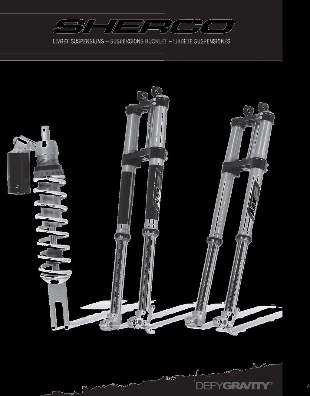

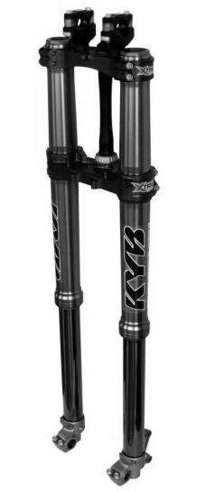
1 KAYABA SUSPENSION
2 Contents KAYABA SUSPENSIONS General remarks 3 1- YOKE Exploded view Maintenance of Gaskets and Rings Disassembly Assembly Cartridge maintenance Replacement of the cartridge gasket Piston segment replacement Piston replacement SHOCK ABSORBER Exploded view Replacement of the spring 23
3 Introduction Introduction General remarks: Pay close attention to the following advice when working on KAYABA products, in strict accordance with the present maintenance manual. Always use tools dedicated for professionals. In addition to a set of common tools, you regularly require KAYABA s special tooling. These individually numbered tools (available through SHERCO) enable you to avoid damaging the parts. Always use protective aluminum plates when clamping our products or our parts in a vice. Always replace damaged or worn parts. Clean all parts prior to their assembly.

4 1- Yoke Exploded view 1. Spy gasket 2. Dust cover 3. External Teflon Guide Ring 4. Internal Teflon Guide Ring 5. Yoke Spring 6. Upper Plug 7. Upper Plug O-Ring Gasket 8. Lower Plug O-Ring Gasket 9. Bleeder Screw 10. Bleeder Screw O-Ring Gasket 12. Counter Plug Spring Guide 16. Plug Nut 19. Cylinder Head 21. Hydraulic System Gasket 22. Hydraulic System Guidance 23. Hydraulic System Ring 24. Free Piston Spring 25. Counter Free Piston Spring Guide 26. Complete Free Piston 27. Free Piston Upper O-Ring Gasket 28. Free Piston Upper Ring 29. Free Piston Lower Ring 30. Free Piston Lower O-Ring Gasket 31. Free Piston Gasket 33. Compression Rod 34. Trigger Rod 36. Aluminum Compression Adjustment Tube 37. Aluminum Pressure Relief Adjustment Tube 42. Compression Adjustment O-Ring Gasket 43. Pressure Relief Adjustment O-Ring Gasket 44. Compression Adjustment Needle 45. Pressure Relief Adjustment Needle 49. Compression Plug 50. Pressure Relief Plug 51. Compression Lock Washer 52. Pressure Relief Lock Washer 53. Compression Distance Washer 54. Pressure Relief Distance Washer 55. Compression Valve Spring 56. Pressure Relief Valve Spring 57. Compression Valve 58. Pressure Relief Valve 59. Compression Piston 60. Pressure Relief Piston 61. Pressure Relief Piston Segment 62. Compression Piston O-Ring Gasket 63. Compression Washer 64. Pressure Relief Washer 65. Compression Nut 66. Pressure Relief Nut 67. Complete Cylinder 68. Washer placed in the Cylinder 73. Upper Spring Distance Cylinder 74. Lower Spring Distance Cylinder 75. Outer sleeve 77. Spy Gasket Washer 78. Gasket Clip 79. Lower Tube (R or L) 80. Base Valve O-Ring Gasket 81. Plug Copper Gasket 82. Counter-Adjustment Nut 83. Pressure Relief Adjustment

5 1.1 - Maintenance of Gaskets and Rings Disassembly Before getting started, it is always necessary to clean the yoke and remove accessories, like the holeshot kits and yoke protector. Check and record both the compression and pressure relief setting positions. Open the compression and pressure relief settings fully. Set the yoke into the vice. Unscrew the upper plug with the yoke plug wrench (ref ). Drain the oil from the sleeve.

6 1.1 - Maintenance of Gaskets and Rings Place the base of the yoke into the vice using aluminum flanges in order to avoid damage. Unscrew the lower pressure relief plug. Push on the upper plug in order for the rod to penetrate the yoke base. Block the pressure relief plug with the rod holder (ref ) Immobilize the nut on the rod using a 15-mm wrench and unscrew the pressure relief plug.

7 1.1 - Maintenance of Gaskets and Rings Remove the adjustment rod. Remove the rod holder (ref ) as well as both the cartridge and spring. Lower the dust cover and remove the clip with a screwdriver. Withdraw the outer sleeve in using a firm motion. Remove the rings, the washer, the spy gasket, the clip and the dust cover. Always replace the spy gaskets. Clean and check the other parts and replace as needed. Clean and verify whether the internal tube has been damaged (sharp teeth); replace it if necessary.
8 1.1 - Maintenance of Gaskets and Rings Assembly Place the internal tube into the vice using aluminum flanges in order to prevent damage. Implement the gasket assembly tool (ref ) on the internal tube. Apply KYB lubricant inside both the dust cover and spy gasket. Assemble: the dust cover the clip the spy gasket Remove the gasket assembly tool (ref ). Slide onto the internal tube: the washer the lower ring the upper ring Assemble the external tube.

9 1.1 - Maintenance of Gaskets and Rings Use the gasket hammer (ref ) to install the guide ring, the washer and the spy gasket in the external tube. Assemble the clip and the dust cover. Check the spring for damage and ensure that the length is correct. Assemble the spring in the internal tube. Place the cartridge in the internal tube. Push the cartridge through the yoke base. Block the pressure relief rod with the rod holder (ref ).
10 1.1 - Maintenance of Gaskets and Rings Assemble the adjustment rod. Verify that the locking nut on the rod is completely screwed. Reminder: When the plug is entirely screwed down, a space of approximately 1.5 mm remains between the plug and the locking nut. Tighten the pressure relief plug and locking nut to 29 Nm. Remove the rod holder (ref ) and screw the pressure relief plug into the base at 50 Nm. Pour the exact quantity of KYB 01M oil into the yoke using a graduated specimen (ref ). To know these exact quantities of oil, please consult Section 7.4.

11 1.1 - Maintenance of Gaskets and Rings Tighten the upper plug. Return both the compression and pressure relief settings to their original positions. Note: Always initiate the calculation from a completely clamped position.
12 1.2.1 Replacement of the cartridge gasket Cartridge maintenance Disassemble the cartridge as described in Section Remove the spring support. Set the cartridge into the vice with the cylinder flange (refs , ). Place the cylinder plug wrench (ref ) in the plug. Completely loosen the upper plug.
13 1.2 - Cartridge maintenance Push the pressure relief rod into the cartridge. ==> the compression plug will then be released. Pour the cartridge oil. Set the pressure relief rod into the vice with the rod flange (ref ). Loosen the locking nut at the bottom of the pressure relief rod. Remove the pressure relief rod by the top of the cylinder.
14 1.2 - Cartridge maintenance Set the cartridge into the vice with the cylinder flange (refs , ). Be sure to set it just above the cylinder head. Heat the cylinder head in order to burn off the loctite. Assemble the cylinder gasket wrench (ref ) in the cylinder head. Reminder: Kayaba Ind. Co. Japan and/or Technical Touch BVBA and their affiliated companies hereby decline all liability for damages (whether personal injury or property damage) caused due to improper assembly of the cartridge subsequent to discarding the cylinder head. Loosen and completely remove the cylinder head. Remove the gasket and backup ring, and then vigorously clean the threading.
15 1.2 - Cartridge maintenance Assemble a new gasket and backup ring. Be sure to respect the gasket direction. Apply the loctite (ex. nr. 243) onto the threading. Tighten the cylinder head to 45 Nm.

16 1.2.2 Piston segment replacement Cartridge maintenance Dismantle the pressure relief rod as explained in Section Set the rod into the vice with the rod flange (ref ). Cut the old segment with a cutter. Stretch a new segment and assemble it on the piston. Push the piston into the calibration tool (refs , ) in order to reduce it to the right measurement.
17 1.2 - Cartridge maintenance Assemble the pressure relief rod inside the cylinder by the top. Completely tighten the locking nut onto the rod. Pour the exact quantity of KYB 01M oil into the cartridge using a graduated specimen (ref ). To know these exact quantities of oil, please consult Section 7.4. Move the rod a few times up and down in order to bleed the cartridge. Set the cartridge into the vice with the cylinder flange (ref ). Carefully insert the compression plug into the cartridge.
18 1.2 - Cartridge maintenance Tighten the plug using the cylinder plug wrench (ref ) at 29 Nm. Maintain the cartridge diagonally with the compression part slightly higher. Push the rod completely into the cartridge for purposes of bleeding the cartridge. Be careful as the excess oil will be released! Assemble the spring support on the cartridge. Continue to assemble the cartridge as described in Section
19 1.2 - Cartridge maintenance Replacement of the free piston Remove the cartridge compression plug as described in Section Raise the cylinder plug wrench (tool ) into the screw. Place the compression system on the plug wrench. Unscrew the compression piston base with a 14- mm wrench. Remove the free piston and replace it by a new one.

20 1.2 - Cartridge maintenance Raise the entire compression piston base to 14 Nm. Assemble the compression system into the cartridge as described in Section

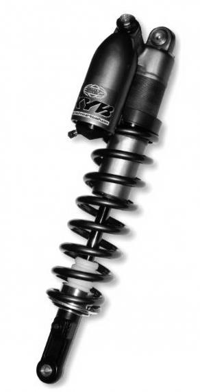
21 2 - Shock Absorber

22 2.1 - Replacement of the spring Place the shock absorber into the vice. Loosen the nuts positioned against the spring. Remove the aluminum washer. Remove the spring. As for the assembly, follow the same phases in the opposite order.
Sachs shock manual. ( ) 2 & 4 Stroke RR Enduro. ( ) RS Dual Sport
 2 & 4 Stroke RR Enduro. ( ) RS Dual Sport") Sachs shock manual (2013 2015) 2 & 4 Stroke RR Enduro (2014-2015) RS Dual Sport 1 Introduction The procedures in this manual must take place in a clean environment using professional tools and some specific,
Sachs shock manual (2013 2015) 2 & 4 Stroke RR Enduro (2014-2015) RS Dual Sport 1 Introduction The procedures in this manual must take place in a clean environment using professional tools and some specific,
Front Fork Disassembling and Assembling RM-Z250L6. KAYABA Pneumatic Spring Front Fork PSF2
 Front Fork Disassembling and Assembling RM-Z250L6 KAYABA Pneumatic Spring Front Fork PSF2 RM-Z250L6 Front Fork Disassembling 1. Release air Release the air pressure by pressing the air valve with a screwdriver.
Sachs 48mm Closed Cartridge fork Service Manual
 Sachs 48mm Closed Cartridge fork Service Manual 1 Fork seal driver 2 Special soft jaws 3 Fork cap wrench 4 Rebound rod holding tool 5 Compression assembly holding tool 6 Retaining clip tool Special Tools
4357 / 4860 MX Multi Adjuster
 12_234 Frontfork 4357 / 4860 MX Multi Adjuster Introduction 2 Exploded view 3 Disassembly forkleg 4 Disassembly screw-cap 15 Assembling screw-cap 17 Disassembly cartridge 18 Disassembly compression holder
Workshop manual 5018 PDS Product Exploded View Disassembly & Assembling. Shock absorber 5018 PDS OEM Shock absorber 5018 PDS /2002
 Shock absorber 5018 PDS OEM 2000 Introduction 2 Exploded view 3 Disassembly shock absorber 4 Disassembly piston-rod 11 Disassembly adaptor DU-bush 15 Assembling adaptor DU-bush 17 Assembling piston-rod
A REPAIR KIT PART NUMBER IS AVAILABLE AND CONTAINS ALL THE PARTS NORMALLY REPLACED DURING A STANDARD MAINTENANCE REPAIR.
 AZ Pump Instructions PUMP NOT RUNNING PROPERLY: Check to be sure air pressure is reaching the pump, check to be sure air filter is not clogged; clean or replace as required. Check to be sure fluid filter
X-Trainer 43mm fork service manual. Beta USA, Inc This work should be performed by a trained motorcycle technician.
 X-Trainer 43mm fork service manual Beta USA, Inc. 2016 This work should be performed by a trained motorcycle technician. Table of contents Page Introduction/special tools... 2 Fork exploded view... 3 Legend.
Marzocchi Suspension MZ I MZ I. Technical instructions
 Technical instructions Exploded view - MZ I - 100 Rif. Code Quantity Spare part list - MZ I - 100 Rif. Code Description Q.ty in the model Technical characteristics: Technical characteristics Single-crown
PS 37. POWER STEERING POWER STEERING LINK (for 4WD) REMOVAL
 REMOVAL") POWER STEERING POWER STEERING LINK (for 4WD) 37 REMOVAL 1. DISCONNECT CABLE FROM NEGATIVE BATTERY TERMINAL 2. PLACE FRONT WHEELS FACING STRAIGHT AHEAD 3. REMOVE FRONT WHEELS 4. REMOVE NO. 1 ENGINE UNDER
POWER STEERING POWER STEERING LINK (for 4WD) 37 REMOVAL 1. DISCONNECT CABLE FROM NEGATIVE BATTERY TERMINAL 2. PLACE FRONT WHEELS FACING STRAIGHT AHEAD 3. REMOVE FRONT WHEELS 4. REMOVE NO. 1 ENGINE UNDER
Servicing front brakes
 46-1 Servicing front brakes C54 brake caliper, servicing Special tools and workshop equipment required VAG 1331 Torque wrench (or equivalent) VAG 1410 Torque wrench (or equivalent) VAG 1869/2 Brake pedal
Marzocchi Suspension MZ III MZ III. Technical instructions
 Technical instructions Exploded view - MZ III - 100 Rif. Code Quantity Spare part list - MZ III - 100 Rif. Code Description Q.ty in the model Technical characteristics: Technical characteristics Single-crown
X-FLY (80) GENERAL. BAM: Bomber Aerospace Material. Special alloy developed from aerospace material. Ø TRAVEL Ø30
 GENERAL. BAM: Bomber Aerospace Material. Special alloy developed from aerospace material. Ø TRAVEL Ø30") (8) 175 8 Ø3 +.5 L.MAX=461 L.L.=451 L.MIN=371 ±2 396 ±2 TRAVEL 8 55 18 Ø3 15 2 -.1 +1 248.5 GENERAL Special air/oil damped cross-country fork: each leg uses pressurized air blown through a special valve
(8) 175 8 Ø3 +.5 L.MAX=461 L.L.=451 L.MIN=371 ±2 396 ±2 TRAVEL 8 55 18 Ø3 15 2 -.1 +1 248.5 GENERAL Special air/oil damped cross-country fork: each leg uses pressurized air blown through a special valve
Super T QR20 INSTRUCTIONS GENERAL RULES
 INSTRUCTIONS GENERAL RULES 1. Where specified, assemble and disassemble the shock absorption system using the MARZOCCHI special tools only. 2. On reassembling the suspension system, always use new seals.
Marzocchi Suspension D-Street 24" D-Street 24" Technical instructions
 Technical instructions Exploded view - D-Street 24" 80 Rif. Code Quantity D-Street 24" 80 - Oil levels Position Oil type Quantity (cc) Right fork leg SAE 7,5-550013 185 Left fork leg SAE 7,5-550013 185
Workshop manual 4618 BAVP 85 SX. Product Exploded View Disassembly & Assembling. Schok absorber 4618 BAVP 85 SX
 Schok absorber Introduction 2 Exploded view 3 Disassembly shock absorber 4 Disassembly piston rod 12 Assembling piston rod 23 Disassembly adaptor DU-bush 33 Assembling adaptor DU-bush 36 Disassembly tube
Char-Lynn Hydraulic Motor. Repair Information Series. April, 1997
 Char-Lynn Hydraulic Motor April, 1997 Repair Information Geroler Motors 002 00 004 Parts Drawing 1 See Note 2 Page 1 22 1 9 1-1/4 Split Flange Ports 8 7 6 5 B 1 See Note 2 Page 2 24 4 14 19 20 15 1 18
DUCATI MONSTER 696/796 CARTRIDGE KIT
 DUCATI MONSTER 696/796 CARTRIDGE KIT INSTALLATION OF THE KYB CARTRIDGE KIT Available for models Ducati Monster 696 and 796 from 2011 to 2014 This manual concerns the installation of the aftermarket KYB
10A 10F 10B 10E 10A 10D 10B. Mr. T 10C Q R
 Q R 2 0 23 30 12 18 17 16 15 14 37 39 38 3 7 6 5 20 26 21 22 40 13 4 2 25 24 8 1 28 27 11 31 19 10A 10D 10B 10C 10 29 10A 10F 10B 10E 10 9 32 36 33 34 35 178 15 GENERAL 82 80 Ø28.6 ±0.1 Ø30 +0.05 0 348
Steering Gearbox Disassembly
 Steering Gearbox Disassembly Steering Rack Disassembly 5. Unbend the lock washer. Before disassembling the gearbox, wash it off with solvent and a brush. Do not dip seals and O-rings in solvent. 1. Remove
TOPAZ Service Guide. Full Service
 TOPAZ Service Guide Full Service SERVICE OVERVIEW This manual will guide you step by step performing an air service to your Topaz. Please follow each instruction carefully to achieve the best and safest
Jr. T GENERAL. BAM: Bomber Aerospace Material. Special alloy extracted from aerospace material. Ø TRAVEL ±
 175 15 GENERAL The double clamp fork is specifically designed for Downhill use. The fork is sprung by a mechanical spring and uses hydraulic rebound damping. Spring pre-load adjustment controlled via external
OCTOPUS SERVICE PROCEDURE - SP007 REV NEW 15-FEB-2008
 OCTOPUS SERVICE PROCEDURE - SP007 REV NEW 15-FEB-2008 APPLICABLE MODELS a. Both styles of Octopus Hydraulic 38mm Bore Linear Drive. (LAM = Linear Actuator Mounted & LAR = Linear Actuator Remote) REQUIRED
Marzocchi Suspension Drop-Off SL Drop-Off SL. Technical instructions. Technical characteristics: Technical characteristics
 Technical instructions Technical characteristics: Technical characteristics Single-crown fork with ø 32mm legs. Available travels: 130mm, 150 mm. Right fork leg damping element: spring (air pre-load).
FRONT FORK 2.16 GENERAL REMOVAL HOME. 4. See Figure Loosen upper and lower fork clamp pinch fasteners (1, 4).
.") FRONT FORK.6 GENERAL The XRScg model utilizes a mm fork assembly while all other models have changed to the mm fork assembly. The front fork consists of two telescoping outer tube/inner slider assemblies.
FRONT FORK.6 GENERAL The XRScg model utilizes a mm fork assembly while all other models have changed to the mm fork assembly. The front fork consists of two telescoping outer tube/inner slider assemblies.
Cylinder Maintenance & Repair Instructions
 Cylinder Maintenance & Repair Instructions PENINSULAR CYLINDER CO. Model HP High Pressure Hydraulic Cylinders Proximity Switch & Non Proximity Switch Designs - High Pressure NFPA Hydraulic Cylinder ( 5,000
WARNING. Indicates a hazardous situation which, if not avoided, could result in death or serious injury. WARNING
 Floating QRS Short Shaft Conversion (Kit P/N 860 200 832) The following symbols may be used in this document: WARNING Indicates a hazardous situation which, if not avoided, could result in death or serious
TR50/60/70/75-SR50/60/75. Repair Manual. General Pump is a member of the Interpump Group. Ref Rev.A 05-15
 TR50/60/70/75-SR50/60/75 Repair Manual 8 General Pump is a member of the Interpump Group GENERAL PUMP A member of the Interpump Group TR50/60/70/75-SR50/65/75 SERIES INDEX 1. INTRODUCTION..................................................Page
Z1 Free Ride (110) GENERAL
 GENERAL") GENERAL (110) 175 80 Ø 30 +0.05 0 L.MAX=493 L.L.=483 ±2 L.MIN=373 426 ±2 57 CORSA 110 TRAVEL 110 18 Ø 30 15 20 0-0.1 +1 0 248.5 Special ride and Downhill fork whose legs are damped by a spiral springs
GENERAL (110) 175 80 Ø 30 +0.05 0 L.MAX=493 L.L.=483 ±2 L.MIN=373 426 ±2 57 CORSA 110 TRAVEL 110 18 Ø 30 15 20 0-0.1 +1 0 248.5 Special ride and Downhill fork whose legs are damped by a spiral springs
Disassembly. 1 Pull off the QUIK-LOK cable from the machine.
 Special Tools Require Important! Torx TX0 bit 0 0 Screwdriver Torx 0 0 0 Forcing Discs 0 Before beginning the maintenance work, perform an initial check with a high voltage test according to VDE (see chapter
This file is available for free download at
 This file is available for free download at http://www.iluvmyrx7.com This file is fully text-searchable select Edit and Find and type in what you re looking for. This file is intended more for online viewing
Features. Marathon SL TECHNICAL CHARACTERISTICS. Sliding bushes: made of friction free and wear free material.
 Features TECHNICAL CHARACTERISTICS Fork with Ø30 mm legs with "Double Air" damping system. Adjustment of the air preload (positive air) on both legs. Adjustment of the rebound damping (negative air) on
Workshop manual 3612 / 4681 BAVP. Product Exploded View Disassembly & Assembling. Shock absorber
 455 Shock absorber 3612/4681 BAVP 02/2002 Shock absorber Introduction 2 Exploded view 3 Adjustment 4 Disassembly shock absorber 5 Disassembly piston-rod 7 Disassembly adaptor DU-bush 15 Disassembly tube
Z1 Free Ride INSTRUCTIONS GENERAL RULES
 INSTRUCTIONS GENERAL RULES 1. Where specified, assemble and disassemble the shock absorption system using the MARZOCCHI special tools only, as shown in the table below. 2. On reassembling the suspension
M-2300-T 6-Piston Mustang Brake Kit INSTALLATION INSTRUCTIONS
 Please visit www.fordracingparts.com for the most current instruction information!!! PLEASE READ ALL OF THE FOLLOWING INSTRUCTIONS CAREFULLY PRIOR TO INSTALLATION. AT ANY TIME YOU DO NOT UNDERSTAND THE
Maintenance Information
 16606022 Edition 3 May 2014 Air Drill 728 Series Maintenance Information Save These Instructions Product Safety Information WARNING Failure to observe the following warnings, and to avoid these potentially
Overhaul Special Tools Required
 1 of 31 Overhaul - Special Tools Required - Cylinder end seal remover attachment, 07NAD-SR3020A - Pilot collar, 07GAF-PH70100 - Valve seal ring sizing tool, 07NAG-SR3090A - Ball joint boot clip guide,
INSTRUCTIONS FOR OVERHAUL OF RAMEY RE SERIES WINCH
 INSTRUCTIONS FOR OVERHAUL OF RAMEY RE 12000 SERIES WINCH DISASSEMBLY 1. Drain oil from gear housing by removing plug # from bottom of gear housing. Remove relief fitting # and reducer # from top of gear
Repair Manual and Spare Parts List
 Pneumatic Drive Unit Type Techn. Doc. No. 352 and Accessories for Pipe Cutting Machine Darstellung kann vom Original abweichen Repair Manual and 580027000_Inst_en_Version_02 Repair General In general,
REPAIRMANUAL
 REPAIRMANUAL2005-2008 WP FORK 4860 ROMA REPARATURANLEITUNG MANUALE DI RIPARAZIONE MANUEL DE RÉPARATION MANUAL DE REPARACIÓN ART.NR.: 3.211.214 1 SPECIAL TOOLS 2 GENERAL INFORMATION 3 DISMOUNTING/MOUNTING
Z5 Coil (80) GENERAL. BAM: Bomber Aerospace Material. Special alloy developed from aerospace material. Ø TRAVEL 80 55
 GENERAL. BAM: Bomber Aerospace Material. Special alloy developed from aerospace material. Ø TRAVEL 80 55") (8) 175 8 Ø3 +.5 L.MAX=461 L.L.=451 L.MIN=371 ±2 396 ±2 TRAVEL 8 55 18 Ø3 15 2 -.1 +1 248.5 GENERAL The fork is sprung by a mechanical coil system and uses hydraulic rebound damping. Spring pre-load adjustment
(8) 175 8 Ø3 +.5 L.MAX=461 L.L.=451 L.MIN=371 ±2 396 ±2 TRAVEL 8 55 18 Ø3 15 2 -.1 +1 248.5 GENERAL The fork is sprung by a mechanical coil system and uses hydraulic rebound damping. Spring pre-load adjustment
Maintenance Information
 16575243 Edition 2 October 2013 Air Screwdrivers 1R Series Maintenance Information Save These Instructions Product Safety Information WARNING Failure to observe the following warnings, and to avoid these
Marzocchi Suspension Drop-Off IV Drop-Off IV. Technical instructions
 Technical instructions Exploded view - Drop-Off IV - 110 Rif. Code Quantity Drop-Off IV - 110 - Oil levels Position Oil type Quantity (cc) Right fork leg SAE 7,5-550013 180 Left fork leg SAE 7,5-550013
DISC BRAKE/DUAL MASTER CYLINDER CONVERSION. Tools, Equipment and Supplies Needed:
 Please take the time to read the enclosed instructions carefully. If you have any questions, call our Product Assistance personnel for clarification. It is important to note that these instructions contain
Maintenance Information
 16573370 Edition 2 February 2014 Air Grinder 99V Series Maintenance Information Save These Instructions Product Safety Information WARNING Failure to observe the following warnings, and to avoid these
Disassembling and assembling transmission
 27-640 Disassembling and assembling transmission Preceding work: Removing and installing transmission with torque converter (27-600). Operation number of operation texts and operation values or standard
3.2 DRIVE TORQUE HUB. Roll, Leak and Brake Testing SECTION 3 - CHASSIS & TURNTABLE. 3-2 JLG Lift
 3.2 DRIVE TORQUE HUB Roll, Leak and Brake Testing 10 LUG PATTERN Torque-Hub units should always be roll and leak tested before disassembly and after assembly to make sure that the unit's gears, bearings
Telephone (925) Fax (925) Lawrence Drive, Livermore, CA 94551
 Fax (925) Lawrence Drive, Livermore, CA 94551") Telephone (95) 454-9500 Fax (95) 454-950 5 Lawrence Drive, Livermore, CA 9455 PARTS MANUAL INDEX STEERABLE DRIVE AXLE ASSEMBLY STEERABLE DRIVE END ASSEMBLY BRAKE CALIPER ASSEMBLY TO USE THIS BOOK:. Refer
Telephone (95) 454-9500 Fax (95) 454-950 5 Lawrence Drive, Livermore, CA 9455 PARTS MANUAL INDEX STEERABLE DRIVE AXLE ASSEMBLY STEERABLE DRIVE END ASSEMBLY BRAKE CALIPER ASSEMBLY TO USE THIS BOOK:. Refer
REMOVAL & INSTALLATION
 REMOVAL & INSTALLATION AXLE SHAFTS & BEARINGS Removal CAUTION: Failure to turn off air suspension power before raising vehicle may result in unexpected inflation or deflation of air springs. DO NOT reconnect
Junior T Ext. Reb. Adjustment
 Technical instructions Exploded view - Junior T Ext. Reb. Adjustment Rif. Code Quantity Junior T Ext. Reb. Adjustment - Oil levels Position Oil type Quantity (cc) Right fork leg SAE 7,5-550013 260 Left
Repair Manual and Spare Parts List
 Hydraulic Drive Unit Type Techn. Doc. No. 362 and Accessories for Pipe Cutting Machine Darstellung kann vom Original abweichen Repair Manual and 580067000_Inst_en_Version_03 Repair General In general,
KIT 8 9 9A Q R 15A 15B. yyy
 ,,,,, yy yyy 3 8 9 9A 6 7 6A 5 3 3 1 11 1 13 14 34 15A 15B 15 16 17 4 5 3 8 6 7 9 31 1 18 19 1 33 4 41 35 39 38 37 36 4 KIT 178 8 8 348 ± L.MAX=51.5 L.L.=5.5 L.MIN=37.5 ± 44 58.5 TAVEL 13 15 1 Ø3 43 48.5
MANUAL GEAR HOUSING (4WD)
") SR26 STEERING MANUAL GEAR HOUSING (4WD) REMOVAL AND INSTALLATION OF MANUAL GEAR HOUSING Remove and install the parts as shown. (MAIN POINTS OF REMOVAL AND INSTALLATION) 1. DISCONNECT UNIVERSAL JOINT (a)
SR26 STEERING MANUAL GEAR HOUSING (4WD) REMOVAL AND INSTALLATION OF MANUAL GEAR HOUSING Remove and install the parts as shown. (MAIN POINTS OF REMOVAL AND INSTALLATION) 1. DISCONNECT UNIVERSAL JOINT (a)
Monster T GENERAL. Travel 175
 Ø22 112.5 175 Ø20 358 L.MAX=728 L.L.=718 ±2 L.MIN=543 267 550.5 142.5 25 155.5 37 ±2 513.5 RAVEL 175 38 +0.5 0 27 ravel 175 17.4 192.5 GENERAL he double plate fork is specifically designed for Downhill
H Low Torque Impact Wrench
 SERVICE MANUAL H8508-3 Low Torque Impact Wrench Serial Code AKW Read and understand all of the instructions and safety information in this manual before operating or servicing this tool. Register this
REPAIR INSTRUCTIONS FIRST STAGE REDUCING VALVE
 REPAIR INSTRUCTIONS REDUCING VALVE EXPLODED VIEW Art. No. 2801, 2808, 2962, 3257, 3580, 3585 JETSTREAM - YOKE 5000 - YOKE ANTI-FREEZE CUP DIFFERENT CONNECTION SECONDARY PART PRIMARY PART BALANCING PART
REAR AXLE AND SUSPENSION RA 1
 REAR AXLE AND SUSPENSION RA1 RA2 REAR AXLE AND SUSPENSION Troubleshooting TROUBLESHOOTING Problem Possible cause Remedy Page Wanders/pulls Tires worn or improperly inflated Replace tires or inflate to
PROPELLER SHAFT PR 3 COMPONENTS
 PR3 COMPONENTS PR4 PR5 REMOVAL (2WD) 1. DISCONNECT FLANGE FROM COMPANION FLANGE ON DIFFERENTIAL (a) Put matchmarks on the flanges. (b) Remove the four and nuts. 2. REMOVE CENTER SUPPORT BEARING FROM FRAME
Zoom and Print Options
 Vehicle» Engine, Cooling and Exhaust» Engine» Timing Components» Service and Repair» Procedures» Timing Drive Components Timing Drive Components Special Tools And Equipment Special Tool(s) Material Material
Maintenance Information
 16605958 Edition 2 May 2014 Air Percussive Rivet Buster Models 9001 and 11001 Maintenance Information Save These Instructions Product Safety Information WARNING Failure to observe the following warnings,
Z3 Coil (80) GENERAL. BAM: Bomber Aerospace Material. Special alloy developed from aerospace material. Ø TRAVEL 80 55
 GENERAL. BAM: Bomber Aerospace Material. Special alloy developed from aerospace material. Ø TRAVEL 80 55") (8) 175 8 Ø3 +.5 L.MAX=461 L.L.=451 L.MIN=371 ±2 396 TRAVEL 8 55 18 Ø3 15 2 -.1 +1 248.5 GENERAL The fork is sprung by a mechanical coil system and uses hydraulic rebound damping. Spring pre-load adjustment
(8) 175 8 Ø3 +.5 L.MAX=461 L.L.=451 L.MIN=371 ±2 396 TRAVEL 8 55 18 Ø3 15 2 -.1 +1 248.5 GENERAL The fork is sprung by a mechanical coil system and uses hydraulic rebound damping. Spring pre-load adjustment
Marzocchi Suspension AM SL / TW AM SL / TW. Technical instructions
 Technical instructions Spare part list - AM SL / TW 130 Rif. Code Description Q.ty in the model Technical characteristics: Technical characteristics Single-crown fork with ø 32mm legs. Available travels:
FKR 105. Mounting Instructions. Cartridge kit for Kawasaki ZX-10R
 Kit Contents Description Part No Pcs Cartridge kit FKR 105 1 O-ring x 008-50 O-ring 0x.5 00576-0 Main spring 9.5 N/mm 07-95 Main spring 10.0 N/mm 07-10 Main spring 10.5 N/mm 07-05 Sticker 00191- Sticker
MASTER CYLINDER INSPECTION
 7-16 CHASSIS A-PDF Split DEMO : Purchase from www.a-pdf.com to remove the watermark Remove the piston assembly. MASTER CYLINDER INSPECTION MASTER CYLINDER Inspect the master cylinder bore for any scratches
Installation Instructions
 Installation Instructions Rear Disc Brake Conversion Kit Item # RC4001, RC4001X Applications: Mopar 7.25, 8.25, 9.25 Axles Thank you for choosing Leed Brakes for your automotive product needs. Before you
Pull out clutch E snap ring and withdraw complete clutch pack of clutch E. 6 HP 26 ZF Getriebe GmbH Saarbrücken CD
 Press down cup spring in the mandrel press with assembly bracket 5x46 002 566 and remove snap ring with suitable pliers. Take out planet carrier and cup spring. Take the O-ring seal off the planet carrier.
DRIVE AXLES. Differentials & Axle Shafts - Corvette
 DESCRIPTION & OPERATION 1998-99 DRIVE AXLES Differentials & Axle Shafts - Corvette A Getrag 625 model differential is used on both the automatic and manual transmissions. Differential carrier and case
Maintenance Information
 16573347 Edition 2 February 2014 Air Grinder Series 88H Maintenance Information Save These Instructions Product Safety Information WARNING Failure to observe the following warnings, and to avoid these
1988 Chevrolet Pickup V SUSPENSION - FRONT (4WD)' 'Front Suspension - "V" Series 1988 SUSPENSION - FRONT (4WD) Front Suspension - "V" Series
' 'Front Suspension - V Series 1988 SUSPENSION - FRONT (4WD) Front Suspension - V Series") 1988 SUSPENSION - FRONT (4WD) Front Suspension - "V" Series DESCRIPTION NOTE: Vehicle serial numbers used in this article has been abbreviated for common reference to Chevrolet and GMC models. Chevrolet
1988 SUSPENSION - FRONT (4WD) Front Suspension - "V" Series DESCRIPTION NOTE: Vehicle serial numbers used in this article has been abbreviated for common reference to Chevrolet and GMC models. Chevrolet
Cylinder and Valve: AirHawk II Air Mask
 Cylinder and Valve: AirHawk II Air Mask MAINTENANCE AND REPAIR MSA 011 (L) Rev. 0 MSA 2010 Prnt. Spec. 10000005389(I) Mat. 10104218 Doc. 10104218 Parts List Cylinder Replacement Kits Item P/N Description
REPAIR MANUAL. Version 02/11/01 CD ZF GETRIEBE GMBH SAARBRÜCKEN
 REPAIR MANUAL 6 HP-26 Version CD ZF GETRIEBE GMBH SAARBRÜCKEN subject to alterations Copyright 2002 all rights reserved and published by ZF Getriebe GmbH, Saarbrücken, Department MKTD No part of this manual
Transmission/Crankshaft/Crank Case
 R.Crank Case Crankshaft L.Crank Case 11-0 11. Transmission/Crankshaft/Crank Case Transmission/Crankshaft/Crank Case Service Information 11-1 Troubleshooting 11-2 Transmission 11-3 Crank Case Disassembly
FORK COMPRESSION AND REBOUND GOLD VALVE INSTALLATION - DIRT 35C/30R SFF
 1501 Pomona Rd, Corona, CA 92880 951.279.6655 racetech.com FORK COMPRESSION AND REBOUND GOLD VALVE INSTALLATION - DIRT 35C/30R SFF FK code 2 part LS FMGV 3521C P Thede 12.3.15 7 pgs
OTECO INC. 2 RESET RELIEF VALVE 2 L.P.T. INLET & OUTLET INSTALLATION & MAINTENANCE MANUAL PART NO
 Page 1 of 9 OTECO INC. 2 RESET RELIEF VALVE 2 L.P.T. INLET & OUTLET INSTALLATION & MAINTENANCE MANUAL PART NO. 130250 Page 2 of 9 TABLE OF CONTENTS 1. PERIODIC MAINTENANCE 2. SPARE PARTS LIST 3. PROCEDURES
5-3. ENGINE BOTTOM END
 BOTTOM END ENGINE DRIVE SHAFT 5-3-1 CRANKCASE Remover: 560012 Installer: 560011 Remover: 560014 Installer: 560013 CRANKSHAFT 5-3-2 WATER PUMP, OIL PUMP Installer: 560025 Remover: 560024 Installer: 560003
Servicing the Tool. Service Kit SERVICE KIT. For all servicing we recommend the use of the service kit (part number (S)).
).") Servicing the Tool Service Kit For all servicing we recommend the use of the service kit (part number 07900-04750(S)). SERVICE KIT ITEM PART Nº DESCRIPTION Nº OFF ITEM PART Nº DESCRIPTION Nº OFF 07900-00002
Servicing the Tool Service Kit For all servicing we recommend the use of the service kit (part number 07900-04750(S)). SERVICE KIT ITEM PART Nº DESCRIPTION Nº OFF ITEM PART Nº DESCRIPTION Nº OFF 07900-00002
SERIES1 NOZZLE CYLINDER REPAIR PROCEDURES
 THE FOLLOWING REPAIR PROCEDURE ENCOMPASSES THESE PHD ML UNITS : - ML309435, ML310142, ML310153, ML310254, ML310295, ML310427, 1) Refer to individual ML exploded view for actual part numbers. 2) Not all
CHAS FRONT FORK FRONT FORK LEGS 4-45 FRONT FORK. Order Job/Part Q ty Remarks
 EAS00647 FRONT FORK FRONT FORK LEGS 30 Nm (3.0 m kg, 22 ft lb) 6 Nm (0.6 m kg, 4.3 ft lb) 30 Nm (3.0 m kg, 22 ft lb) Order Job/Part Q ty Remarks 2 3 4 5 Removing the front fork legs Front wheel Front brake
Shock Absorber for Formula Student and Formula SAE TTX 25. Workshop Manual
 Shock Absorber for Formula Student and Formula SAE TTX 5 Workshop Manual SAFETY PRECAUTIONS General Warnings Note! The shock absorber is an important part of the vehicle and will affect the stability.
POWER STEERING TO INDEX POWER STEERING SYSTEM PRECAUTIONS... OPERATION CHECK... PROBLEM SYMPTOMS TABLE... VANE PUMP ASSEMBLY COMPONENTS...
 TO INDEX STEERING POWER STEERING POWER STEERING SYSTEM PRECAUTIONS.............................................. OPERATION CHECK......................................... PROBLEM SYMPTOMS TABLE.................................
Installation Guidelines
 JUSV4-K (metal lever handle) & GUSVR (rough) JUSV4-K (white porcelain lever handle) & GUSVR (rough) JUSV43-K (black porcelain lever handle-mto) & GUSVR (rough) 5 " Shower Outlet Tub Outlet 3 "± " IMPORTANT
Service Tools. Service and Repair Manual Model 900/950/990 ITEM PART NO. DESCRIPTION ITEM PART NO. DESCRIPTION ITEM PART NO.
 12 1 3 2 4 5 8 10 6 7 9 11 14 24 12 13 17 22 29 18 23 25 19 26 15 20 27 21 16 22 33 37 38 32 31 36 30 34 35 40 41 42 43 ITEM PART NO. DESCRIPTION 1 9170 0231 30 LONG ALLEN KEY 2 9170 0737 20 3/32 PIN PUNCH
REMOVAL & INSTALLATION
 REMOVAL & INSTALLATION REAR BRAKE CALIPER NOTE: For rear disc pad removal and installation, DO NOT disconnect brake hose from caliper (wire aside). Replace all pads on an axle if wear indicator on any
STEERING SYSTEM - MANUAL RACK & PINION
 STEERING SYSTEM - MANUAL RACK & PINION 1993 Nissan Sentra 1993 STEERING Nissan Manual Rack & Pinion NX, Sentra DESCRIPTION & OPERATION Steering gear assembly is a manual rack and pinion type. Unit is mounted
PARTSBOOK. Hall Manufacturing, Inc E. Washington Ave., P.O. Box Drawer 5638 North Little Rock, AR (501)
") 540 RPM 2 PARTSBOOK This part of the manual contains part numbers and illustrations based on the latest information available at the time of print. Hall Manufacturing, Inc. reserves the right to make changes
540 RPM 2 PARTSBOOK This part of the manual contains part numbers and illustrations based on the latest information available at the time of print. Hall Manufacturing, Inc. reserves the right to make changes
ONYX VALVE CO MODEL DAO-PFC Installation & Maintenance
 ONYX VALVE CO MODEL DAO-PFC Installation & Maintenance OPERATION: (4-2010) The Onyx DAO-PFC pinch valve is an open frame valve without housing enclosure and fails closed on loss of air. The actuator drives
INSTRUCTION MANUAL INSTALLING NEW GREASE IN UT SERIES PNEUMATIC ACTUATOR
 INSTRUCTION MANUAL INSTALLING NEW GREASE IN UT SERIES PNEUMATIC ACTUATOR This instruction manual explains the steps required to degrease and install new grease into the Max-Air UT series pneumatic actuator.
BETTIS ACTUATOR & CONTROLS SERVICE INSTRUCTIONS FIELD CONVERSION OF SPRING CARTRIDGE FAIL DIRECTION CLOCKWISE TO COUNTER-CLOCKWISE OR THE INVERSE
 BETTIS ACTUATOR & CONTROLS SERVICE INSTRUCTIONS FIELD CONVERSION OF SPRING CARTRIDGE FAIL DIRECTION CLOCKWISE TO COUNTER-CLOCKWISE OR THE INVERSE FOR THE FOLLOWING SERIES T3XX-SRX AND T4XX-SRX SPRING RETURN
POWER ASSISTED SYSTEM (POWER STEERING) PS
 PS") POWER ASSISTED SYSTEM (POWER STEERING) PS Page 1. General Description...2 2. Steering Wheel...23 3. Universal Joint...24 4. Tilt Steering Column...26 5. Steering Gearbox [LHD MODEL]...29 6. Steering Gearbox
POWER ASSISTED SYSTEM (POWER STEERING) PS Page 1. General Description...2 2. Steering Wheel...23 3. Universal Joint...24 4. Tilt Steering Column...26 5. Steering Gearbox [LHD MODEL]...29 6. Steering Gearbox
Z3 Air (80) GENERAL. BAM: Bomber Aerospace Material. Special alloy developed from aerospace material. Ø TRAVEL 80 L.MAX=461 L.L.=451 L.
 GENERAL. BAM: Bomber Aerospace Material. Special alloy developed from aerospace material. Ø TRAVEL 80 L.MAX=461 L.L.=451 L.") (80) 175 18 80 Ø30 +0.05 0 55 L.MAX=461 L.L.=451 L.MIN=371 396 ±0,1 TRAVEL 80 ±2 Ø30 15 20 0-0.1 +1 0 248 GENERAL Special air/oil damped cross-country fork: each leg uses pressurized air blown through
(80) 175 18 80 Ø30 +0.05 0 55 L.MAX=461 L.L.=451 L.MIN=371 396 ±0,1 TRAVEL 80 ±2 Ø30 15 20 0-0.1 +1 0 248 GENERAL Special air/oil damped cross-country fork: each leg uses pressurized air blown through
Model BP6150. Triplex Ceramic Plunger Pump Operating Instructions/ Manual
 Model BP6150 Triplex Ceramic Plunger Pump Operating Instructions/ Manual Contents: Installation Instructions: page 2 Pump Specs: page 3 Exploded View: page 4 Parts List / Kits Torque Specifications: page
ONYX VALVE CO MODEL CAR, CAP-PFO Installation & Maintenance
 ONYX VALVE CO MODEL CAR, CAP-PFO Installation & Maintenance OPERATION: (4-2010) The Onyx series CAR-PFO and CAP-PFO pinch valves fail open on loss of air. The simple spring and air bag arrangement drives
REMOVAL TF REMOVE TRANSFER INDICATOR SWITCH (a) Remove the switches and gaskets. HINT: Indicator switch:
 Remove the switches and gaskets. HINT: Indicator switch:") 20 NO. 1 NO. 2 F043499 REMOVAL 1. DISCONNECT CABLE FROM NEGATIVE BATTERY TERMINAL CAUTION: Wait at least 90 seconds after disconnecting the cable from the negative (-) battery terminal to prevent airbag
20 NO. 1 NO. 2 F043499 REMOVAL 1. DISCONNECT CABLE FROM NEGATIVE BATTERY TERMINAL CAUTION: Wait at least 90 seconds after disconnecting the cable from the negative (-) battery terminal to prevent airbag
MAINTENANCE PROCEDURE FOR MK18/MK16
 MAINTENANCE PROCEDURE FOR MK18/MK16 MK16/MK18-1/1- MAINTENANCE PROCEDURE FOR MK 16 / 18 1 ST STAGES WARNING: this maintenance procedure is only for appointed Scubapro technicians that followed a complete
ON VEHICLE REPAIR AT 27
 AUTOMATIC TRANSMISSION (A43D) Onvehicle Repair AT27 ONVEHICLE REPAIR Valve Body REMOVAL OF VALVE BODY 1. CLEAN TRANSMISSION EXTERIOR To prevent contamination, clean the exterior of the transmission. 2.
PS 23. POWER STEERING POWER STEERING LINK (for 2WD)
") 23 ZK08184E02 ZK08184E01 ZX09355E03 16. INSPECT TIE ROD END SUB-ASSEMBLY LH (a) Flip the ball joint stud back and forth 5 times as shown in the illustration, before installing the nut. (b) Using a torque
23 ZK08184E02 ZK08184E01 ZX09355E03 16. INSPECT TIE ROD END SUB-ASSEMBLY LH (a) Flip the ball joint stud back and forth 5 times as shown in the illustration, before installing the nut. (b) Using a torque
1992 Mitsubishi 3000GT VR-4
 TIMING BELT Removal (Diamante SOHC) 1. Remove left front and left side splash shields. Using engine hoist, lift engine just enough to remove weight from engine mounts. Remove drive belts. Remove A/C tensioner
SUSPENSION AND AXLE SA 1 SUSPENSION AND AXLE
 SA1 SA2 Troubleshooting TROUBLESHOOTING Problem Possible cause Remedy Front Page Rear Wanders/pulls Tires worn or improperly inflated Wheel alignment incorrect Hub bearing worn Front or rear suspension
Timing Belt: Service and Repair Installation NOTE: Check the water pump for water leakage and the oil seal for oil leakage.
 1991 Daihatsu Truck Rocky L4-1589cc 1.6L SOHC Page 1 Timing Belt: Service and Repair Installation NOTE: Check the water pump for water leakage and the oil seal for oil leakage. Repair any water leakage
Installation Instructions
 Preparing your vehicle to install your brake system upgrade 1. Rack the vehicle. 2. If you don t have a rack, then you must take extra safety precautions. 3. Choose a firmly packed and level ground to
Maintenance Information
 80234313 Edition 2 May 2014 Air Grinder, Die Grinder, Sander and Belt Sander Series G1 (Angle) Maintenance Information Save These Instructions Product Safety Information WARNING Failure to observe the