About the Instructions:
|
|
|
- Eustacia Hensley
- 5 years ago
- Views:
Transcription


1 About the Instructions: The Mass Air Modifier is very easy to install and configure. The print instructions and YouTube videos are very detailed on purpose. This detail is intended to provide you with the best possible visual technical product support. Off-Road Notice: Installation of this product signifies that you have read this document and agree to it s terms. This product is for Off-Road or Racing use only. It is up to the user to follow the instructions and to determine the compatibility of this product with the intended vehicle and/or other manufacturer s products. If installed or used improperly, catastrophic engine damage could occur and/or the JMS Mas Air Modifier might be damaged. JMS Chip and Performance LLC assumes no liability or responsibility for any damages incurred from the use of this product. Product Warnings: Suppression type spark plug wires must be used to avoid RFI/EMI issues. JMS Mass Air Modifier must be mounted inside the vehicle cabin or in the trunk. Install the unit so it does not come into contact with water or engine heat. The unit must be mounted away from ignition components or other EMI sources (ignition boxes, coil, spark plug wires). Take care to avoid hitting the Mass Air Modifier. The switches used to program the unit can be damaged. Switches that are broken due to neglect are not eligible to be covered under warranty. PERFORMANCE FUEL SYSTEM PARTS
2 Kit Contents: Ӻ Ӻ (1) JMS Mass Air Modifier part number 4001 or 4002 Ӻ Ӻ (1) Plug and Play Brand Specific Wire Harness (Ford/GM). Connects to your existing mass-air flow sensor. Ӻ Ӻ (1) Installation Parts Package (ring terminals, wire tap, self tapping screws, tie straps) Device Overview: The JMS Mass Air Modifier has been designed to accurately Scale and Filter a MAF signal. All adjustments can be made live on the fly. Once configured the MAF signal is shifted and filtered whenever the unit is ON. The Mass Air Modifier is ON whenever the ignition key is in the ON position (Green Power LED is ON). Configuration is simple, there is no need for a laptop, all you need is the enclosed screwdriver. Configuration Switch Overview: Turn Switch 1 (ON) - configure the Scale Amount or Percentage of MAF Signal Shift Up or Down. Ӻ Ӻ Turn Switch 2 (ON) - configure the amount of Mass Air Signal Filtering. Turn Switch 3 (ON) - configure the Filter Window. The Filter functions ONLY when the vehicle is operating within the Filter Window. The Filter Window can monitor the MAF Signal or an external 0-5v sensor either a - Pedal Position Sensor[PPS], Throttle Position Sensor [TPS] or Manifold Pressure Sensor [MAP]. Turn Switch 8 (ON) - Learn the MAF Signal or Monitored 0-5V value at Idle. Case Dimensions: Silver Aluminum Case with four mounting tabs. LENGTH: 3 3/4 WIDTH: 2 1/2 HEIGHT: 1 1/2 Operating Voltage Range: 9.5V - 20V DC Vehicle Compatibility: Compatible with all 12V or 16V battery systems pn: Digital Mass Air Sensor (Hz) pn: Analog Mass Air Sensor (0-5 Volts) Works with all Stock or Aftermarket Recalibrated Mass Air Sensors Device Inputs & Outputs: Mass Air Sensor: Plug and Play OEM Style Connectors. Plugs into MAF Sensor and the OEM vehicle harness. Six Pin Connector: Plugs directly into the Mass Air Modifier Unit External 0-5V Monitor: White Wire, Select Filter Window Input (exits harness near the MAF Connectors). White Wire Connected to Ground -> Filter Window Input = MAF Signal White Wire Connected to 0-5v DC Sensor Output -> Filter Window Input connected to an Electronic Throttle Body, PPS, TPS or other external sensor. Filter Disable: Yellow Wire, Enable/Disable Filter (exits harness near the SIX pin connector) If the Yellow Wire is connected to Ground, Manually disables Mass Air Signal Filtering (used in setup).
 Ӻ Configure the SCALE Rotary Switch Setting (use the instructions and video as a")
3 QuIcK start guide Ӻ Plug the Mass Air Modifier Harness into the MAF Sensor and the Vehicle Harness (use the video as a guide) Ӻ Route the cable into the vehicle cab and connect the Mass Air Modifier to the Six Pin Connector Ӻ Choose your Filter Window Input (either Ground the White Wire or connect to a 0-5v sensor) Ӻ Configure the SCALE Rotary Switch Setting (use the instructions and video as a guide) Ӻ Configure the FILTER Rotary Switch Setting (use the instructions and video as a guide) Ӻ Configure the FILTER Window Dip Switch Setting (use the instructions and video as a guide) Ӻ Modify your ECU calibration to match using the JMS Mass Air Modifier Spreadsheet Ӻ The MAM can be used to SCALE or FILTER the MAF OUTPUT or it can do both at the same time. Ӻ Use it to sort out COLD or HOT Start fuel problems (shift the MAF Rich or Lean to see what corrects the issue). JMS Mass Air Modifier Tuning Software Calibration Spreadsheet To generate new values Copy and paste MAF values from Tuning Software into the spreadsheet (green cells) Select the approprate MAF TAB (spreadsheet bottom) Enter the MAM Scale Switch value (light blue cell at top) Copy the Yellow Values into your Tuning Software (Spreadsheet Modified Values)

4 Mass Air Modifier Installation Diagram or
 & Pn:4002(AnAlog) Plug and Play Design Real Time On the")
")

5 mass AIr modifier overview & InstAll two mam versions - Pn: 4001(dIgItAl) & Pn:4002(AnAlog) Plug and Play Design Real Time On the Fly MAF Signal Changes High Precision, High Reliability First Product with a built in adjustable Filter PN Digital MAF (Frequency) PN Analog MAF (Voltage) Quality Shielded Cable Not made in China! What is the difference between MAM pn: 4001 (digital) & pn: 4002 (analog)?

6 What does the SCALE Feature do? What else can the Mass Air Modifier do? Filter - Electronic Air Flow Straightener (Laminar)
")

7 Filter Example 1) Digital MAM pn 4001 (2012 Ford Focus) Filter Example 2) Analog MAM pn 4002 (2000 Supercharged Mustang GT)


8 Filter Example 3) LS3 MAF Transition from Minimum to Maximum - pn Six Pin MAM Connector


9 View of the Six Pin Connector plugged into the side of the Mass Air Modifier Yellow Wire - Ground Yellow Wire to disable MAM Filter

")
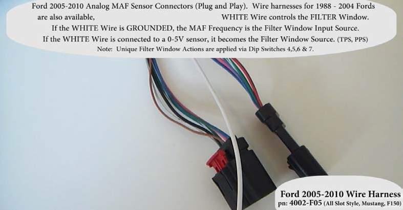
10 GM Plug and Play Wire Harness - pn 4001-GM1 or pn 4001-GM2 Ford Plug and Play Wire Harness (Digital MAF) pn: F11

11


12 Mass Air Modifier Kit Includes - MAM Unit, Install Kit & Wire Harness Ford Specific Install Step 1 - Route MAM Cable and Plug into MAF and Harness


13 Ford Specific Install Step 2 - Route MAM Cable into cab and plug 6 pin into MAM. GM Specific Install Step 1- Route MAM Cable and Plug into MAF and Harness


14 GM Specific Install Step 1a - Route MAM Cable and Plug into MAF and Harness GM Specific Install Step 2 - Route MAM Cable into cab and plug 6 pin into MAM


15 Ford & GM MAM Install Step 3 - Choose MAM Filter Input (Ground or connect to sensor)
 Set dip switches 4,5,6,7 & 8 OFF.")
16 Mass Air Modifier Configuration Instructions How to configure the Mass Air Modifier so it does NOT MODIFY the MAF Signal Step 1) Set dip switches 4,5,6,7 & 8 OFF. Set both rotary switches to position 1
17 Step 2) Set Dip Switches 1, 2 & 3 - ON (Programming Mode is entered after 2 seconds) Step 3) Set Dip Switches 1,2 & 3 - OFF (LED s Twinkle - Save Settings)

 to save")
18 Procedure to learn the IDLE Value of MAF Sensor or Monitored External Sensor Verify that the vehicle is at idle. Turn ONLY Dip SW 8 (ON) After 10 seconds the led s will flash in QUICK rotation sequence Turn Dip Switch 8 (OFF) to save learned idle value
.")
 Make your adjustment to the Scale switch.")
19 How to configure the SCALE rotary switch Step 1) Set Dip Switch 1 (ON). After 2 seconds the Scale LED will blink slowly Step 2) Make your adjustment to the Scale switch. Adjustments are Live On the Fly
20 Scale Rotary Switch Settings 1 = Stock No change 9 = 25% Less (Leaner) 2 = 1% Less (Leaner) 10 = 30% Less (Leaner) 3 = 2% Less (Leaner) 11 = 35% Less (Leaner) 4 = 3% Less (Leaner) 12 = 5% More (Richer) 5 = 4% Less (Leaner) 13 = 4% More (Richer) 6 = 10% Less (Leaner) 14 = 3% More (Richer) 7 = 15% Less (Leaner) 15 = 2% More (Richer) 8 = 20% Less (Leaner) 16 = 1% More (Richer) Note: The scale percentage values are the same for both the digital (period) and analog (voltage) MAM units. Step 3) Turn Dip Switch 1 (OFF) to save the Scale rotary switch setting
 Make your")

21 How to configure the Filter Rotary Switch Step 1) Set Dip Switch 2 (ON). After 2 seconds the FILTER LED will blink slowly Step 2) Make your adjustment to the filter switch. Filter adjustments are Live On the Fly Amount of filtering goes up with the filter switch values - 1 = Min Filter, 16 = Max Filter
 Digital MAM pn 4001 (2012 Ford")
22 Step 3) Turn Dip Switch 2 (OFF) to save the Filter rotary switch setting Filter Example 1) Digital MAM pn 4001 (2012 Ford Focus)
 Make your adjustment to the Filter Window Dip")
23 How to configure the Filter Window dip switches Step 1) Set Dip Switch 3 (ON). After 2 seconds the Power LED will blink slowly Step 2) Make your adjustment to the Filter Window Dip Switches (4,5,6) Adjustments are Live

 to save the Filter")
24 Step 3) If the White Wire is monitoring a 0-5V sensor input. To invert for 5-0v Signal switch 7 (ON) Step 4) Turn Dip Switch 3 (OFF) to save the Filter Window Settings (Power LED will Twinkle)
25 Filter Window Input Dip Switch Settings - Digital MAF Mass Air Modifier pn 4100 : White Wire Connected to Ground (Filter Window uses MAF Frequency as INPUT) Filter from IDLE to (IDLE+1500Hz) - (SW 4 - OFF)(SW 5 - OFF)(SW 6 - OFF) Filter from IDLE to (IDLE+1000Hz) - (SW 4 - ON)(SW 5 - OFF)(SW 6 - OFF) Filter from IDLE to (IDLE+500Hz) - (SW 4 - OFF)(SW 5 - ON)(SW 6 - OFF) Filter from (IDLE+640Hz) to (IDLE+1640Hz) - (SW 4 - ON)(SW 5 - ON)(SW 6 - OFF) Filter from (IDLE+1280Hz) to (IDLE+2280Hz) - (SW 4 - OFF)(SW 5 - OFF)(SW 6 - ON) Filter from (IDLE+1920Hz) to (IDLE+2920Hz) - (SW 4 - ON)(SW 5 - OFF)(SW 6 - ON) Filter from (IDLE+2560Hz) to (IDLE+3560Hz) - (SW 4 - OFF)(SW 5 - ON)(SW 6 - ON) Filter from (IDLE+3200Hz) to (IDLE+4200Hz) - (SW 4 - ON)(SW 5 - ON)(SW 6 - ON) White Wire Connected to 0-5 V Input(Filter Window uses External Sensor as INPUT) - [TPS, PPS, MAP]) Filter from IDLE to (IDLE+100 Counts[0.48v]) - (SW 4 - OFF)(SW 5 - OFF)(SW 6 - OFF) Filter from IDLE to (IDLE+40 Counts[0.19v] - (SW 4 - ON)(SW 5 - OFF)(SW 6 - OFF) Ӻ Ӻ Filter from (IDLE+30 Counts[0.14v]) to (IDLE+110 Counts[0.53v]) - (SW 4 - OFF)(SW 5 - ON)(SW 6 - OFF) Filter from (IDLE+60 Counts[0.29v]) to (IDLE+140 Counts[0.68v]) - (SW 4 - ON)(SW 5 - ON)(SW 6 - OFF) Filter from (IDLE+90 Counts[0.44v]) to (IDLE+170 Counts[0.83v]) - (SW 4 - OFF)(SW 5 - OFF)(SW 6 - ON) Filter from (IDLE+120 Counts[0.58v]) to (IDLE+200 Counts[0.97v]) - (SW 4 - ON)(SW 5 - OFF)(SW 6 - ON) Filter from (IDLE+150 Counts[0.73v]) to (IDLE+230 Counts[1.12v]) - (SW 4 - OFF)(SW 5 - ON)(SW 6 - ON) Filter from (IDLE+180 Counts[0.87v]) to (IDLE+260 Counts[1.27v]) - (SW 4 - ON)(SW 5 - ON)(SW 6 - ON)
26 Filter Window Input Dip Switch Settings - Analog MAF Mass Air Modifier pn 4200 : White Wire Connected to Ground (Filter Window uses MAF Voltage as INPUT) Filter from IDLE to (IDLE+350 Counts[1.71v]) - (SW 4 - OFF)(SW 5 - OFF)(SW 6 - OFF) Filter from IDLE to (IDLE+250 Counts[1.22v]) - (SW 4 - ON)(SW 5 - OFF)(SW 6 - OFF) Filter from IDLE to (IDLE+150 Counts[0.73v]) - (SW 4 - OFF)(SW 5 - ON)(SW 6 - OFF) Filter from (IDLE+50 Counts[0.24v]) to (IDLE+350 Counts[1.71v]) - (SW 4 - ON)(SW 5 - ON)(SW 6 - OFF) Filter from (IDLE+75 Counts[0.36v]) to (IDLE+375 Counts[1.83v]) - (SW 4 - OFF)(SW 5 - OFF)(SW 6 - ON) Filter from (IDLE+100 Counts[0.48v]) to (IDLE+400 Counts[1.95v]) - (SW 4 - ON)(SW 5 - OFF)(SW 6 - ON) Filter from (IDLE+150 Counts[0.73v]) to (IDLE+450 Counts[2.19v]) - (SW 4 - OFF)(SW 5 - ON)(SW 6 - ON) Filter from (IDLE+200 Counts[0.97v]) to (IDLE+500 Counts[2.44v]) - (SW 4 - ON)(SW 5 - ON)(SW 6 - ON) White Wire Connected to 0-5 V Input (Filter Window uses External Sensor as INPUT) - [TPS, PPS, MAP] Filter from IDLE to (IDLE+100 Counts[0.48v]) - (SW 4 - OFF)(SW 5 - OFF)(SW 6 - OFF) Filter from IDLE to (IDLE+40 Counts[0.19v]) - (SW 4 - ON)(SW 5 - OFF)(SW 6 - OFF) Ӻ Ӻ Filter from (IDLE+30 Counts[0.14v]) to (IDLE+110 Counts[0.53v]) - (SW 4 - OFF)(SW 5 - ON)(SW 6 - OFF) Filter from (IDLE+60 Counts[0.29v]) to (IDLE+140 Counts[0.68v]) - (SW 4 - ON)(SW 5 - ON)(SW 6 - OFF) Filter from (IDLE+90 Counts[0.44v]) to (IDLE+170 Counts[0.83v]) - (SW 4 - OFF)(SW 5 - OFF)(SW 6 - ON) Filter from (IDLE+120 Counts[0.58v]) to (IDLE+200 Counts[0.97v]) - (SW 4 - ON)(SW 5 - OFF)(SW 6 - ON) Filter from (IDLE+150 Counts[0.73v]) to (IDLE+230 Counts[1.12v]) - (SW 4 - OFF)(SW 5 - ON)(SW 6 - ON) Filter from (IDLE+180 Counts[0.87v]) to (IDLE+260 Counts[1.27v]) - (SW 4 - ON)(SW 5 - ON)(SW 6 - ON)
27 Led Details: Power green led - Six potential states: OFF = Unit is not powered. Vehicle is OFF or the MAM Unit is not plugged into 6 pin or MAF Vehicle Harness. ON Solid = MAM unit is powered and functioning. Slow Flash = Dip Switch 3 (ON) - Configuring Filter Window Range via Dip Switches 4-7. Twinkle = Dip Switch 3 (OFF) - Power LED Twinkles while saving the Filter Window Dip Switch Values (sw 4-7). Note: Fast and Slow Rotation Sequence = Learn Idle Values, LEDS Sequence ON/OFF from Bottom to Top Slow Rotation Sequence = Dip Switch 8 (ON) - Sampling the Idle MAF Value and 0-5V external sensor value Fast Rotation Sequence = Dip Switch 8 (ON) - Idle MAF and 0-5v external sensor values have been learned. Scale red led - Five potential states: OFF = Operate using Saved SCALE Rotary Switch Value from Memory Slow Flash = Dip Switch 1 (ON) - Configure SCALE Rotary Switch Setting: If you Adjust the SCALE Rotary Switch the MAF Signal is Modified Live, On the Fly. Twinkle = Dip Switch 1 (OFF) - Scale LED Twinkles while saving the SCALE Rotary Switch Value. Note: Fast and Slow Rotation Sequence = Learn Idle Values, LEDS Sequence ON/OFF from Bottom to Top Slow Rotation Sequence = Dip Switch 8 (ON) - Sampling the Idle MAF Value and 0-5V external sensor value Fast Rotation Sequence = Dip Switch 8 (ON) - Idle MAF and 0-5v external sensor values have been learned. Filter red led - Five potential states: OFF = Operate using Saved FILTER Rotary Switch Value from Memory Slow Flash = Dip Switch 2 (ON) - Configure FILTER Rotary Switch Setting: If you Adjust the FILTER Rotary Switch the MAF Signal is Filtered Live, On the Fly. Twinkle = Dip Switch 1 (OFF) - FILTER LED Twinkles while saving the FILTER Rotary Switch Value. Note: Fast and Slow Rotation Sequence = Learn Idle Values, LEDS Sequence ON/OFF from Bottom to Top Slow Rotation Sequence = Dip Switch 8 (ON) - Sampling the Idle MAF Value and 0-5V external sensor value Fast Rotation Sequence = Dip Switch 8 (ON) - Idle MAF and 0-5v external sensor values have been learned Wire Harness & Color Information: activation wires: White Wire (18 gauge) - This wire determines which Filter Input to use. If connected to GROUND the MAF Signal itself will be used as the Filter Input. If connected to monitor a 0-5V Signal the 0-5V signal will be used as the Filter Input (external sensor [Pedal Position or Throttle Position or Manifold Pressure]) Yellow Wire (18 gauge) - Grounded = Disable the Filter Not Connected = Filter is Operational six wire connector: Pin 1 Yellow - Enable Circuit 1 (ground enable) Pin 2 Black - Ground / Wire Shield Pin 3 Red - +12V Power Pin 4 Blue - Modified MAM Output to ECU Pin 5 Brown - Input from MAF Sensor Pin 6 White - Filter Input Select: Ground = Use MAF Signal as Filter input or connect to 0-5V ext sensor.
Thank you for your purchase Off-ROad NOtice: PROduct WaRNiNgs:
 Thank you for your purchase. Please, read the instructions and watch the video before installing the JMS Progressive N20 Controller. Configuration and installation videos are available online: www.jms-nos.com.
CAUTION: CAREFULLY READ INSTRUCTIONS BEFORE PROCEEDING
 Daytona Sensors LLC Engine Controls and Instrumentation Systems Installation Instructions for Wide-Band Exhaust Gas Oxygen Sensor Interface CAUTION: CAREFULLY READ INSTRUCTIONS BEFORE PROCEEDING OVERVIEW
Thank you for your purchase.
 Thank you for your purchase. Please read the complete installation instructions or view the video instructions on YouTube before attempting to install this product. If not installed properly, PowerMAX
CAUTION: CAREFULLY READ INSTRUCTIONS BEFORE PROCEEDING
 Daytona Sensors LLC Engine Controls and Instrumentation Systems Installation Instructions for WEGO II Wide-Band Exhaust Gas Oxygen Sensor Interface Methanol Version CAUTION: CAREFULLY READ INSTRUCTIONS
MALLORY FIRESTORM CD MULTI COIL HARDWARE INSTALLATION - PN 69050S / 69050R
 FORM 69050S/R MALLORY FIRESTORM CD MULTI COIL HARDWARE INSTALLATION - PN 69050S / 69050R To ensure you are using the most current instruction sheet, please visit www.malloryfirestorm.com. CAUTION! The
CAUTION: CAREFULLY READ INSTRUCTIONS BEFORE PROCEEDING
 Daytona Sensors LLC Engine Controls and Instrumentation Systems Installation Instructions for Wide-Band Exhaust Gas Oxygen Sensor Interface CAUTION: CAREFULLY READ INSTRUCTIONS BEFORE PROCEEDING OVERVIEW
MAF Translator / Translator Plus Installation/Description (Version 5.x)
") Installation The MAF Translator and Translator Plus are easy to install. The MAF Translator is a simple plug-in, while the Translator Plus requires connection of the Spark signals into the vehicle's electrical
Installation The MAF Translator and Translator Plus are easy to install. The MAF Translator is a simple plug-in, while the Translator Plus requires connection of the Spark signals into the vehicle's electrical
MALLORY FIRESTORM CD MULTI COIL HARDWARE INSTALLATION - PN 69150C / 69150R
 FORM 69150C/R MALLORY FIRESTORM CD MULTI COIL HARDWARE INSTALLATION - PN 69150C / 69150R To ensure you are using the most current instruction sheet, please visit www.malloryfirestorm.com. CAUTION! The
The kit comes with a 100 psi sensor, solenoids and harness.
 AMS-500 V2 Boost Controller Overview The AMS-500 V2 Boost Controller is a time based graph style controller. It has a launch input which is used by transbrake input or clutch input. Both the activation
Installation Instructions. Instinct Shock Controller. Part # Instinct Shock Controller. Installation Instructions
 Part # 82010013 - Instinct Shock Controller Instinct Shock Controller Installation Table of contents Page 2... Included components Page 3... ECU Installation Page 4... GSensor Installation Page 5... Sensors
2009 Yamaha Apex Snowmobile
 PARTS LIST 2009 Yamaha Apex Snowmobile Installation Instructions quantity description 1 power commander 1 USB cable 1 cd-rom 1 installation guide 2 power commander decals 2 dynojet decals 2 velcro strip
2011 Yamaha Apex Snowmobile
 PARTS LIST 2011 Yamaha Apex Snowmobile Installation Instructions quantity description 1 power commander 1 USB cable 1 cd-rom 1 installation guide 2 power commander decals 2 dynojet decals 2 velcro strip
Thank you for your purchase. Instructions support the following vehicles: Reasons to choose BoostMAX!
 Thank you for your purchase. Please read the complete installation instructions or view the video instructions on YouTube before attempting to install this product. If not installed properly, will not
JMS Technical Center Lucedale, MS
 Company Overview About JMS Chip & Performance For more than 22 years, JMS Chip & Performance has been an industry leader in late model domestic and import vehicle tuning. JMS brand electronics components
GENERAL MOTORS SERVICE PARTS OPERATION 6200 Grand Pointe Drive, Grand Blanc, MI 48439
 LS IGNITION CONTROLLER 19355418 Ignition Control for Carbureted LS Series Engines (24x Crankshaft Index/1x Camshaft Index, 58x Crankshaft Index/4x Camshaft Index) Parts Included Quantity Ignition Controller
EFI HARNESS KIT , & Kit Contents: Power Harness : All Kits
 EFI HARNESS KIT 558-500, 558-501 & 558-502 Kit Contents: Main Harness 558-102: Kits 558-500 558-103: Kits 558-501 & 502 Power Harness 558-308: All Kits Injector Harness 558-200: Kits 558-500 & 502 558-201:
Installation Instructions for: EMS P/N Ford Mustang 5.0L
 Installation Instructions for: EMS P/N 30-1401 1994-95 Ford Mustang 5.0L! WARNING: This installation is not for the tuning novice nor the PC illiterate! Use this system with EXTREME caution! The AEM EMS
Sea Doo 4-Tec Supercharged 1500cc Watercraft (Throttle By Wire models) Dynojet CMDM-6212
 Dynojet CMDM-6212") 2009-2012 Sea Doo 4-Tec Supercharged 1500cc Watercraft (Throttle By Wire models) Dynojet CMDM-6212 2012 Dynojet Research, Inc. All Rights Reserved. 2009-2012 Sea Doo 4-Tec Supercharged 1500cc Watercraft
2009-2012 Sea Doo 4-Tec Supercharged 1500cc Watercraft (Throttle By Wire models) Dynojet CMDM-6212 2012 Dynojet Research, Inc. All Rights Reserved. 2009-2012 Sea Doo 4-Tec Supercharged 1500cc Watercraft
ACCEL Distributor Model #A557
 FORM 1627 REV1 INSTALLATION INSTRUCTIONS ACCEL Distributor Model #A557 CAUTION: CAREFULLY READ INSTRUCTIONS BEFORE PROCEEDING. NOT LEGAL FOR USE OR SALE ON POLLUTION CONTROLLED VECHICLES OVERVIEW ACCEL
BigStuff3 - GEN3. 1st Gear Spark Retard with Spark Retard Traction Control System (SR 2 ) Rev
 Rev") BigStuff3 - GEN3 1st Gear Spark Retard with Spark Retard Traction Control System (SR 2 ) 12-09 System Description 1st Gear Spark Retard with Spark Retard Traction Control System (SR 2 ) - SR 2 uses two
BigStuff3 - GEN3 1st Gear Spark Retard with Spark Retard Traction Control System (SR 2 ) 12-09 System Description 1st Gear Spark Retard with Spark Retard Traction Control System (SR 2 ) - SR 2 uses two
SCHNITZ MOTORSPORTS USER MANUAL AND INSTALLATION GUIDE PRO-MOD BATTERY VOLTS DIAGNOSTICS NOS PULSE FREQUENCY NOS DELAY TIME IN SECONDS
 SCHNITZ MOTORSPORTS DSC-CS "PRO-MOD" IGNITION CONTROLLER USER MANUAL AND INSTALLATION GUIDE COIL, (OPTIONAL) GA YELLOW, COIL, NEGATIVE GA WHITE, GA BLACK, SHIFT LIGHT +V OUTPUT PAGE 0 NOS ACTIVATION INPUT
Greddy E-manage Installation and Tuning Information
 Greddy E-manage Installation and Tuning Information Overview The Emanage has a lot of functionality considering it is still a piggyback type engine management system and not a full standalone. By itself,
Innovative Racing Electronics
 MPS Fast FI Mixture Control Installation Instructions The MPS Fast FI Mixture Control P/N 1-0337 is a simple means to adjust the fuel curves on your fuel-injected motorcycle. This allows for tuning after
CAUTION: CAREFULLY READ INSTRUCTIONS BEFORE PROCEEDING
 Daytona Sensors LLC Engine Controls and Instrumentation Systems Installation Instructions for WEGO IIID Wide-Band Exhaust Gas Oxygen Sensor Interface (Automotive Version) CAUTION: CAREFULLY READ INSTRUCTIONS
TELORVEK EFI 5.0 Coyote Sequential Fuel Injection System Part # CY-11
 Page #1 TELORVEK EFI 5.0 Coyote Sequential Fuel Injection System Part # CY-11 WIRING INSTRUCTIONS Thank you for purchasing the absolute finest of wiring kits for the Ford Motor Co. Coyote modular engine.
CAUTION: CAREFULLY READ INSTRUCTIONS BEFORE PROCEEDING
 Twin Tec Installation Instructions for Wide-Band Exhaust Gas Oxygen Sensor System CAUTION: CAREFULLY READ INSTRUCTIONS BEFORE PROCEEDING OVERVIEW The is a complete air/fuel ratio (AFR) metering system
FUEL MOTO MICRO EFI TUNER POLARIS RZR800 / S / 4. 1 Micro Tuner Module 1 USB Cable 1 Alcohol swab. 1 Installation Guide 2 Velcro 2 Zip ties
 FUEL MOTO MICRO EFI TUNER INSTALLATION INSTRUCTIONS 2011-2014 POLARIS RZR800 / S / 4 PARTS LIST 1 Micro Tuner Module 1 USB Cable 1 Alcohol swab 1 Installation Guide 2 Velcro 2 Zip ties PLEASE READ ALL
PLEASE READ ALL DIRECTIONS BEFORE STARTING INSTALLATION
 PARTS LIST FUEL and IGNITION 2016-2018 Honda Pioneer 1000 Installation Instructions 1 Power Commander 1 USB Cable 1 Installation Guide 2 Power Commander Decals 2 Dynojet Decals 2 Velcro strips 1 Alcohol
PLEASE READ ALL DIRECTIONS BEFORE STARTING INSTALLATION
 Parts List 2006-2014 Yamaha Stratoliner/Roadliner 2008-2013 Yamaha Raider Installation Instructions 1 Power Commander FC 1 USB Cable 1 Installation Guide 2 Dynojet Decals 2 Velcro 1 Alcohol swab 1 O2 Optimizer
DFE PARTS LIST INSTALLATION INSTRUCTIONS PLEASE READ ALL DIRECTIONS BEFORE STARTING INSTALLATION
 1 Fusion Module 1 USB Cable 1 Installation Guide PARTS LIST INSTALLATION INSTRUCTIONS 2 Velcro Strips 1 Alcohol Swab 1 O2 Optimizer 2014 KAWASAKI TERYX 4 DFE-17-054 PLEASE READ ALL DIRECTIONS BEFORE STARTING
Thank you for your purchase.
 Thank you for your purchase. Please read the complete installation instructions or view the video instructions on YouTube before attempting to install this product. If not installed properly, PowerMAX
SCHNITZ MOTORSPORTS PNC-202, 2-STAGE PROGRESSIVE NITROUS CONTROLLER USER MANUAL AND INSTALLATION GUIDE NOS PULSE FREQUENCY
 SCHNITZ MOTORSPORTS PNC-202, 2-STAGE PROGRESSIVE NITROUS CONTROLLER USER MANUAL AND INSTALLATION GUIDE NOS #2, FUEL SOLENOID(GROUND) 1GA PURPLE, PAGE 14 NOS #2 NITROUS SOLENOID(GROUND) 1GA PURPLE, PAGE
Manual Version 1.02 MAF Translator Gen-II version 1.02
 Manual Version 1.02 version 1.02 Table of Contents Kit Contents:...- 3 - Available Accessories and Options:...- 3 - Introduction:...- 3 - Main Airflow Modes...- 4 - Installation Details...- 4 - Installation....-
Lingenfelter Launch Control Module
 Installation Instructions For Lingenfelter Launch Control Module Adjustable Launch Controller & RPM Limiter For GM LSx Series Engines NOW With Timing Retard Mode PN: L4615297 1557 Winchester Road Decatur,
INSTALLATION INSTRUCTIONS UNLEASH. THE SMARTEST PERFORMANCE TUNING TECHNOLOGY
 INSTALLATION INSTRUCTIONS R UNLEASH. THE SMARTEST PERFORMANCE TUNING TECHNOLOGY FUEL MANAGEMENT FUEL + QS + TRACTION CONTROL HONDA GROM 2014-2017 F393 T393 1>READ WARNINGS > INSTALLING We strongly suggest
PLEASE READ ALL DIRECTIONS BEFORE STARTING INSTALLATION
 PARTS LIST 2007-2013 Arctic Cat 800cc and 1000cc Snowmobiles Installation Instructions 1 Power Commander 1 USB Cable 1 CD-ROM 1 Installation Guide 2 Power Commander Decals 2 Dynojet Decals 2 Velcro Strips
OFF-ROAD ELECTRONIC IGNITION CONTROL
 INSTALLATION INSTRUCTIONS FORM 1678M 05/07 OFF-ROAD ELECTRONIC IGNITION CONTROL GENERAL INFORMATION This ignition includes a single stage RPM limiter. You can set various settings using the switches that
Innovative Racing Electronics
 FOR IMMEDIATE RELEASE Contact: Dan Rudd Phone: 407.330.9727 FAX: 407.322.8632 E-Mail: sales@mpsracing.com Web: www.mpsracing.com Holley Commander 950 Universal 4 Cylinder Fuel Injection Kit Sanford, Florida,
Ford Coyote Main Harness and Harness Kit PN , , and
 Ford Coyote Main Harness and Harness Kit PN 558-110, 550-619, and 550-625 This wiring harness interfaces a Holley EFI ECU to a Ford Coyote engine that has either had the cam VVT hardware locked out or
PSC1-003 Programmable Signal Calibrator
 PSC1-003 Programmable Signal Calibrator Description: The PSC1-003 Programmable Signal Calibrator provides precise calibration of fuel by adjusting fuel control signals. It can be used with naturally aspirated
QUICK START GUIDE 199R10546
 QUICK START GUIDE 199R10546 1.0 Overview This contains detailed information on how to use Holley EFI software and perform tuning that is included within the software itself. Once you load the software,
Throttle Sensitivity Booster
 U 1 New version allows for optional control switch. See page 4 for details. Throttle Sensitivity Booster Apps Booster 1057730 (Manual trans only) Vehicle / Year 1998.5-2003 Dodge Cummins DO NOT INSTALL
PLATINUM. Sport Haltech 13B Terminated Engine Harness QUICK START GUIDE
 PLATINUM Sport 1000 Haltech 13B Terminated Engine Harness QUICK START GUIDE HALTECH HEAD OFFICE: PH: +612 9729 0999 FAX: +612 9729 0900 EMAIL: sales@haltech.com HALTECH US OFFICE: EMAIL: usa@haltech.com
MSD LS-1/LS-6 Controller for Carbureted and EFI Gen III Engines PN 6010
 MSD LS-1/LS-6 Controller for Carbureted and EFI Gen III Engines PN 6010 Parts Included 1 Ignition Controller, PN 6010 1 Pro-Data+ Software CD 1 Harness 1 Parts Bag 6 Timing Modules Optional Accessories
GM LS3 Throttle Body and ECU Kit
 OMEX PERFORMANCE ELECTRONICS GM LS3 Throttle Body and ECU Kit An easy to install kit to convert the GM LS3 engine to a cable operated throttle and premapped user programmable ECU suitable for both IVA
DFS-1000 Wiring Diagrams and PC Software Installation.
 DFS-1000 Wiring Diagrams and PC Software Installation. For Technical Support Please contact your dealer or email seellc@mchsi.com 1 Important Information - When using a conventional style ignition coil
Arctic Cat M8, M1000, F8, and F1000 Snowmobiles
 PARTS LIST 2009-2010 Arctic Cat M8, M1000, F8, and F1000 Snowmobiles Installation Instructions quantity description 1 power commander 1 USB A to mini B cable 1 cd-rom 1 installation guide 2 power commander
Thank you for your purchase.
 Thank you for your purchase. Please read the complete installation instructions or view the video instructions on YouTube before attempting to install this product. If not installed properly, PowerMAX
MSD LS Ignition Control PN 6014/60143
 MSD LS Ignition Control PN 6014/60143 ONLINE PRODUCT REGISTRATION: Register your MSD product online. Registering your product will help if there is ever a warranty issue with your product and helps the
Lingenfelter ECSS-001 Ethanol Content Sensor Signal Simulator Installation & Operating Instructions
 Lingenfelter ECSS-001 Ethanol Content Sensor Signal Simulator Installation & Operating Instructions PN: L460350085 Revision - 1.6 Lingenfelter Performance Engineering 1557 Winchester Road Decatur, IN 46733
FAST XIM. XIM Unit Installation
 1 INSTRUCTIONS XIM Thank you for choosing products; we are proud to be your manufacturer of choice. Please read this instruction sheet carefully before beginning installation, and also take a moment to
Accel 300+ Ignition Control System (84-95) - Installation Instructions
 - Installation Instructions") Accel 300+ Ignition Control System (84-95) - Installation Instructions The below installation instructions work for the following products: Accel 300+ Ignition Control System (84-95) Please read through
Accel 300+ Ignition Control System (84-95) - Installation Instructions The below installation instructions work for the following products: Accel 300+ Ignition Control System (84-95) Please read through
MSD 6LS-2 Ignition Controller for Carbureted and EFI LS 2/LS 7 Engines PN 6012
 MSD 6LS-2 Ignition Controller for Carbureted and EFI LS 2/LS 7 Engines PN 6012 ONLINE PRODUCT REGISTRATION: Register your MSD product online. Registering your product will help if there is ever a warranty
for 86 and 87 Buick Turbo V6 and 89 Turbo Trans Am
 for 86 and 87 Buick Turbo V6 and 89 Turbo Trans Am Scanmaster Instructions Power Up On initial key-on, the right-most decimal point will flash quickly to indicate that data is being received. The Scanmaster
Ford Coyote Non-VVT Main Harness PN
 Ford Coyote Non-VVT Main Harness PN 558-114 This wiring harness interfaces a Holley EFI ECU to a Ford Coyote engine that has had the cam VVT hardware locked out. It is meant to be used in conjunction with
Direct Link Basic Tuning Guide (Delphi)
") Direct Link Basic Tuning Guide (Delphi) This Guide is intended to answer basic Direct Link tuning questions and to act as a Quick Start Guide. It is not intended to be the Gospel on the tuning process
Direct Link Basic Tuning Guide (Delphi) This Guide is intended to answer basic Direct Link tuning questions and to act as a Quick Start Guide. It is not intended to be the Gospel on the tuning process
Asynchronous Restriking CDI 2 channel
 Asynchronous Restriking CDI 2 channel Parts List ARC-2 module Decals Power Cable Fuse Specifications Operating Voltage: 8-20V Operating Current: Max Operating RPM: Ambient Temp range: Ignition inputs:
Speed Sentinel II Programmable Road Speed Limiter
 An ISO 9001:2008 Registered Company Speed Sentinel II Programmable Road Speed Limiter SS501-A, SS501-AX Ford E Series 2005-2008 Ford F250-F550 Series 2008-2010 Ford Crown Victoria 2005-2008 Contact InterMotive
PLEASE READ ALL DIRECTIONS BEFORE STARTING INSTALLATION
 Parts List 2008-2014 Honda CBR1000RR Installation Instructions 1 Power Commander FC 1 USB Cable 1 Installation Guide 2 Dynojet Decals 2 Velcro 1 Alcohol swab 1 O2 Optimizer THE IGNITION MUST BE TURNED
PLEASE READ ALL DIRECTIONS BEFORE STARTING INSTALLATION
 PARTS LIST 2006-2014 Suzuki M109R / C109R Installation Instructions 1 Power Commander 1 USB Cable 1 Installation Guide 2 Power Commander Decals 2 Dynojet Decals 2 Velcro strips 1 Alcohol swab 1 Zip tie
Installation Instructions for Lingenfelter Shift Light Controller with green LED
 Installation Instructions for Lingenfelter Shift Light Controller with green LED PN: L460080000 1557 Winchester Road Decatur, Indiana 46733 260 724 2552 phone 260 724 8761 fax www.lingenfelter.com Parts
Controller Ground (dual black 12awg) should be connected to chassis ground as close as possible to the battery.
 should be connected to chassis ground as close as possible to the battery.") 1. Overview The Maximizer 4 progressive nitrous controller operates one or two separate stages of nitrous based on either time, RPM, MPH, throttle percentage or boost pressure. Whether your engine is naturally
1. Overview The Maximizer 4 progressive nitrous controller operates one or two separate stages of nitrous based on either time, RPM, MPH, throttle percentage or boost pressure. Whether your engine is naturally
M-9424-M50CJ INTAKE MANIFOLD INSTALLATION INSTRUCTIONS
 Please visit www.fordracingparts.com for the most current instruction information!!! PLEASE READ ALL OF THE FOLLOWING INSTRUCTIONS CAREFULLY PRIOR TO INSTALLATION. AT ANY TIME YOU DO NOT UNDERSTAND THE
PLEASE READ ALL DIRECTIONS BEFORE STARTING INSTALLATION
 Parts List 2008-2011 Yamaha TMax 500 Installation Instructions 1 Power Commander FC 1 USB Cable 1 Installation Guide 2 Dynojet Decals 2 Velcro 1 Alcohol swab THE IGNITION MUST BE TURNED OFF BEFORE INSTALLATION!
PLEASE READ ALL DIRECTIONS BEFORE STARTING INSTALLATION
 Parts List 2004-2007 Honda CBR1000RR Installation Instructions 1 Power Commander FC 1 USB Cable 1 Installation Guide 2 Dynojet Decals 2 Velcro 1 Alcohol swab THE IGNITION MUST BE TURNED OFF BEFORE INSTALLATION!
PLEASE READ ALL DIRECTIONS BEFORE STARTING INSTALLATION
 Parts List 2013-2014 Honda CBR600RR Installation Instructions 1 Power Commander FC 1 USB Cable 1 Installation Guide 2 Dynojet Decals 2 Velcro 1 Alcohol swab 1 O2 Optimizer THE IGNITION MUST BE TURNED OFF
Mallory HyFire Electronic Ignition Control
 Mallory HyFire Electronic Ignition Control PN 690 Parts Included: 1 - Ignition 1 - Harness, Mag Pickup 1-18" Ground Wire 1-100V/1A Diode 4 - Mounting Screws WARNING: During installation, disconnect the
Using the Gratec Gasoline software
 Using the Gratec Gasoline software The Gratec Software is a sophisticated yet user friendly program in which configures the Gratec CNG or LPG system to perform with your vehicle. Software version 2.002
1. Index. LS Wiring Harness. 2. Presentation Warnings and Warranty Terms Overview Labels...7
 OWNER S MANUAL 1. Index 2. Presentation...4 3. Warnings and Warranty Terms...5 4. Overview...6 5. Labels...7 6. Diagrams...7 6.1 FT500/FT500 Aux - Inputs/outputs...7 6.2 Nano WB O2 #1...8 6.3 Nano WB
Harley Davidson V-Rod Models
 2801190 REV. 8-11-05 User Manual 2002-2005 Harley Davidson V-Rod Models Part Number DFCH-5 Congratulations on your purchase of this Dynatek product. Please take a moment to read these instructions completely
Installation Guide. Thank you for the purchase of our product. You have just unleashed infinite control, power and ability into your hands.
 Installation Guide Thank you for the purchase of our product. You have just unleashed infinite control, power and ability into your hands. This product is for race use only by experienced engine tuners.
ECO3-601/602 EcoStar III * Chevy Express/GMC Savana Contact Intermotive for additional vehicle applications
 An ISO 9001:2015 Registered Company ECO3-601/602 EcoStar III 2009-2019* Chevy Express/GMC Savana Contact Intermotive for additional vehicle applications * In 2017-2018, the ignition switches on Chevy Express
MODEL MVX-2011 TANK MOUNT SPEEDOMETER/TACHOMETER
 MODEL MVX-2011 TANK MOUNT SPEEDOMETER/TACHOMETER Wiring Diagram The MVX-2011 gauges will work on 2011-up Softail models with 5 gauges or 2012-up Dyna models with 5 gauges. It is a direct plug in on these
CAUTION: CAREFULLY READ INSTRUCTIONS BEFORE PROCEEDING.
 Twin Tec Installation Instructions for Ignition CAUTION: CAREFULLY READ INSTRUCTIONS BEFORE PROCEEDING. OVERVIEW Twin Tec ignition is states street legal (ARB E.O. No. D--) for use with the following Harley-Davidson
TABLE OF CONTENTS. If you have any questions during the installation of this product, please H&S Motorsports support at
 TROUBLESHOOTING: Note: You will have a check engine light and/or other problems unless using this product with a compatible ECM calibration. Contact your tuning supplier to learn whether or not aftermarket
advanced FLOW engineering Instruction Manual P/N: SCORCHER BLUE Bluetooth Power Module
 advanced FLOW engineering Instruction Manual P/N: 77-84009 SCORCHER BLUE Bluetooth Power Module Make: Chevrolet Model: Colorado Year: 2016-2019 Engine: I4-2.8L (td) Duramax (LWN) Make: GMC Model: Canyon
Installation Instructions for: EMS P/N Ford Mustang 5.0L
 Installation Instructions for: EMS P/N 30-1400 1986-93 Ford Mustang 5.0L! WARNING: This installation is not for the tuning novice nor the PC illiterate! Use this system with EXTREME caution! The AEM EMS
advanced FLOW engineering Instruction Manual P/N: Make: Ford Model: F-150 Raptor Year: Engine: V6-3.
 advanced FLOW engineering Instruction Manual P/N: 77-83023 Make: Ford Model: F-150 Raptor Year: 2017-2018 Engine: V6-3.5L (tt) EcoBoost Please read the entire instruction manual before proceeding. Ensure
Delphi / GM MEFI-4b (P/N ) ECUs to CD-7 Displays
 ECUs to CD-7 Displays") Revision Date Initial Release May 23, 2017 Delphi / GM MEFI-4b (P/N 12584052) ECUs to CD-7 Displays Supported Channels The CD-7 supports the following 59 data channels that could be transmitted by the
Revision Date Initial Release May 23, 2017 Delphi / GM MEFI-4b (P/N 12584052) ECUs to CD-7 Displays Supported Channels The CD-7 supports the following 59 data channels that could be transmitted by the
Honda VTX1800
 2801191 Rev 06-28-05 User Manual 2002-2005 Honda VTX1800 Part Number DFCM-1 Congratulations on your purchase of this Dynatek product. Please take a moment to read these instructions completely before installing
V8 Gen. V Ford Mustang 2010 Update
 V8 Gen. V Ford Mustang 2010 Update There were several updates to the Ford Mustang in the 2010 model year. This document outlines the differences between the installation steps necessary for the 2010 Mustang
MGL Avionics EFIS G2 and iefis
 MGL Avionics EFIS G2 and iefis Guide to using the MGL RDAC CAN interface with the LAD AERO Injection Kit on ROTAX 912-912S General... 3 Data connections... 3 LAD AERO ROTAX 912 engine data from ECU...
PLEASE READ ALL DIRECTIONS BEFORE STARTING INSTALLATION
 PARTS LIST FUEL AND IGNITION 2014-2015 Yamaha Bolt 950 Installation Instructions 1 Power Commander 1 USB Cable 1 Installation Guide 2 Power Commander Decals 2 Dynojet Decals 2 Velcro strips 1 Alcohol swab
HYFIRE 6AL2 ELECTRONIC IGNITION CONTROL
 INSTALLATION INSTRUCTIONS FORM 1643 HYFIRE 6AL2 ELECTRONIC IGNITION CONTROL PART NO 6861M PARTS INCLUDED: 1 HYFIRE 6AL2 Ignition Control 4 #10 Sheet Metal Screws 2 Wire Ties 2 Ring Terminals, Insulated
JB N20/N26 Stage 1 & JB4 Install Guide Last Updated: 10/31/2017
 JB N20/N26 Stage 1 & JB4 Install Guide Last Updated: 10/31/2017 Use subject to terms and conditions posted at http://www.burgertuning.com/terms.html THIS PART IS LEGAL FOR USE ONLY IN COMPETITION RACING
CAUTION: READ INSTRUCTIONS CAREFULLY BEFORE STARTING INSTALLATION
 V-Twin MFG. VT No. 32-9500 V-TECH 1 IGNITION KIT, SINGLE FIRE FITS EV SHOVEL, XL THRU 1997 VT No. 32-9503 V-TECH 1 IGNITION KIT, SINGLE FIRE FITS EV, SHOVEL, XL, WITH COIL AND WIRES This is a custom application
ELITE 1000/1500 Dodge SRT QUICK START GUIDE HT
 E N G I N E M A N A G E M E N T S Y S T E M S ELITE 1000/1500 Dodge SRT4 03-05 QUICK START GUIDE HT-140940 LIMITED WARRANTY Lockin Pty Ltd trading as Haltech warrants the HaltechTM Programmable Fuel Injection
Electronic Over-Boost Protection System With Vent-to-Atmosphere Valve Control And 4 Bar Map Sensor Output Installation and User Guide
 Stratified guardian angel v3 Electronic Over-Boost Protection System With Vent-to-Atmosphere Valve Control And 4 Bar Map Sensor Output Installation and User Guide Guardian Angel V3 Installation and User
Gen III HEMI Harness PN or
 Gen III HEMI Harness PN 558-106 or 558-107 This wiring harness interfaces a Holley EFI ECU to a Gen III HEMI engine. It is meant to be used in conjunction with an injector harness, a coil harness, and
Lingenfelter NCC-002 Nitrous Control Center Quick Setup Guide
 Introduction: Lingenfelter NCC-002 Nitrous Control Center Quick Setup Guide The NCC-002 is capable of controlling two stages of progressive nitrous and fuel. If the NCC-002 is configured only for nitrous,
TABLE OF CONTENTS PARTS LIST
 TROUBLESHOOTING: Note: You will have a check engine light and/or other problems unless using this product with a compatible ECM calibration. Contact your tuning supplier to learn whether or not aftermarket
DynoTune Wideband Gauge
 DISPLAY: RED GREEN BLUE DynoTune Wideband Gauge FACE: BLACK WHITE BEZEL: BLACK SILVER PACKAGE: ROUND SQUARE The DynoTune A/F Gauge will display the air/fuel ratio output from the LC-1 Wide-Band controller.
E-STREET 2 EFI IGNITION CONTROL KIT Part #3674, 3675, 3676, 3679, 3680 INSTALLATION INSTRUCTIONS
 E-STREET 2 EFI IGNITION CONTROL KIT Part #3674, 3675, 3676, 3679, 3680 INSTALLATION INSTRUCTIONS PLEASE study these instructions carefully before beginning this installation. Most installations can be
Cannondale Diagnostic Tool Manual
 Cannondale Diagnostic Tool Manual For vehicles (ATV & Motorcycles) equipped with the MC1000 Engine Management System Software CD P/N 971-5001983 Data Cable P/N 971-5001984 POTENTIAL HAZARD Running the
ARCTIC CAT M8, M1000, F8, AND F1000 SNOWMOBILES INSTALLATION INSTRUCTIONS
 2007-2009 ARCTIC CAT M8, M1000, F8, AND F1000 SNOWMOBILES INSTALLATION INSTRUCTIONS PARTS LIST quantity description button adjustment display 1 power commander 1 USB A to mini B cable 1 cd-rom 1 installation
PLEASE READ ALL DIRECTIONS BEFORE STARTING INSTALLATION
 PARTS LIST FUEL AND IGNITION 2014 Suzuki GW250 Installation Instructions 1 Power Commander 1 USB Cable 1 CD-ROM 1 Installation Guide 2 Power Commander Decals 2 Dynojet Decals 2 Velcro strips 1 Alcohol
Speed Sentinel Programmable Road Speed Limiter
 An ISO 9001:2008 Registered Company Speed Sentinel Programmable Road Speed Limiter SS531-A, SS531-AX, SS531-AND Ford E Series 2005-2012 Ford F Series 2008-2010 Ford Crown Victoria 2005-2008 Contact InterMotive
PLEASE READ ALL DIRECTIONS BEFORE STARTING INSTALLATION
 PARTS LIST 2017 Victory 106 Models Installation Instructions 1 Power Commander 1 USB Cable 1 Installation Guide 2 Power Commander Decals 2 Dynojet Decals 2 Velcro strips 1 Alcohol swab 2 O2 Optimizers
Throttle Sensitivity Booster
 U 21 March 2018 1057730-1057737 Throttle Sensitivity Booster (I-00358) 1 DOWNLOAD COLOR INSTALL MANUALS AT dieselperformance.com New version allows for optional control switch. See page 4 for details.
INSTALLATION INSTRUCTIONS
 INSTALLATION INSTRUCTIONS 275+ & 300+ STREET / STRIP DIGITAL MULTI-STRIKE CD IGNITION CONTROLLER GENERAL INFORMATION The features of the 275+ and 300+ Ignitions are the same, with one exception: the 300+