Installation Instructions. Instinct Shock Controller. Part # Instinct Shock Controller. Installation Instructions
|
|
|
- Caren Robinson
- 5 years ago
- Views:
Transcription

1 Part # Instinct Shock Controller Instinct Shock Controller Installation Table of contents Page 2... Included components Page 3... ECU Installation Page 4... GSensor Installation Page 5... Sensors Installation Page 5... Speed Sensor Calibration Page 6... Mode Switch Installation/Operation Page 7... Launch Control Mode Page 7... Set-Up Mode Pages Drive By Wire TPS Calibration
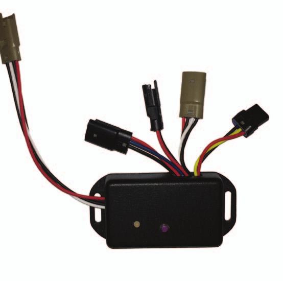


2 Major Components...In the box Installation Item # Part # Description QTY ECU Main Harness GSensor Mode Select Harness - Included in Main Harness 1 5 GSensor Extension Harness - Included in Main Harness Brake Pressure Sensor Harness Speed Sensor Harness Universal Throttle Position (TPS) Harness
 Communication to GSensor (brown, male, 4 wires) use supplied extension harness Green/Yellow Twisted = CAN NOT USED { Shock Connectors ECU Connector Brown")


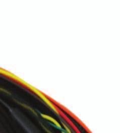
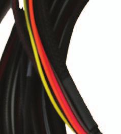
3 Instinct ECU Installation 8. Mode Selector Switch (brown, female, 4 wires) Communication to GSensor (brown, male, 4 wires) use supplied extension harness Green/Yellow Twisted = CAN NOT USED { Shock Connectors ECU Connector Brown and Black = Ground Red = +12V at Battery Orange = +12V at Battery Yellow = +12V Switched Ignition 1. First lay out the harness in the vehicle with the main ECU connector located at the rear, typically in the trunk on the seat back support or under the package tray. Ensuring there is enough wire length to adequately reach the shocks at each corner. 2. Locate a suitable location to mount the ECU. On the seat back support or under the package tray are popular options. 3. Mark and drill two holes and utilize the appropriate mounting hardware for your installation to secure the ECU enclosure. 4. Plug in the wire harness and begin routing wire through the vehicle. The shocks at each corner have a dedicated connector with a label. The GSensor communication wires should be run down the center of the vehicle. The Extension Harness supplied will plug into the GSensor and the Main Harness. The Mode Selector Switch plugs into the harness that runs with the Front Shock Harness. 3

4 GSensor Installation 5. The GSensor should be mounted low and as close to the center of the vehicle as possible. Typically this means on the transmission tunnel or center console, just under the dash area. This provides a secure location with easy access to the wiring. The sensor should be mounted as level with the ground as possible, with the mounting flanges on the bottom (like it was sitting on a table), with the wires protruding pointing to the rear of the vehicle. Programming Button LED Indicator Front of Vehicle Brake Pressure Sensor (black, male, 3 wires) (yellow wire) NOT USED (brown, female,4 wires) Throttle Position Sensor (black, female, 3 wires) (blue wire) Speed Sensor (black, female, 2 wires) Communication to ECU (long pigtail) (brown, female) (4 wires) Hook and Loop fastener (Velcro) is the preferred mounting method as it s quick, easy, removable, and the GSensor prefers slight vibration isolation from the vehicle. You will need to access the Programming Button on the GSensor when calibrating vehicle speed, so it needs to be accessible at least once after installation. (you can have it hidden, so long as you pull it out to learn vehicle speed, then hide it once again). Plug in each sensor as illustrated in the image above. 6. Install the Mode Selector Switch by locating a suitable mounting location, within the drivers reach while belted into the car. Drill a ½ hole and insert the Mode Selector Switch connector first into the hole. Route the Mode Selector Switch wire (Brown Female Plug, 4 wire) from the main harness to the Mode Selector and plug in. (see step #4) Mode Selector Switch Harness is located in the Main Harness with the front shock connectors. 4
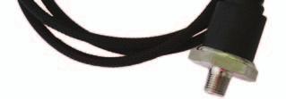
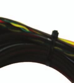
5 Instinct Sensor Installation 7. Install the Sensors: 7a. Brake Pressure Sensor (Black Male Plug - 3 wire - yellow wire - short pigtail) The Brake Pressure Sensor should be installed in the front brake circuit. Typically the easiest, most convenient location is directly off the master cylinder using a T fitting. Route the wire harness to the GSensor and plug it in as indicated in the image above. 7b. Throttle Position Sensor (Black Female Plug - 3 wire - blue wire - short pigtail) Installation of the TPS sensor depends on your application. If you are using a drive by wire GM LS Series or Ford Coyote it is as simple as unplugging the throttle pedal and plugging in the Ridetech TPS adapter harness. If you ordered a Engine Specific DBW Kit, the kit will include a Y Adapter Harness. If you are utilizing a different fuel injected motor you will need to utilize the Universal Ridetech TPS harness, connecting the black wire to the ground at the OE TPS sensor, and the red wire to the 0-5V signal wire of the OE TPS sensor. Please reference your particular applications wiring documentation for proper connections. If you are running a carburetor you will need to source a TPS kit that fits your particular carb, and utilize the Universal Ridetech TPS harness to plug it into the GSensor. Whichever option you have, route the wire harness to the GSensor and plug it in as indicated in the image above. 7c. Vehicle Speed Sensor (Black Female Plug - 2 wire - short pigtail) Connect the Ridetech Vehicle Speed Sensor harness to any pulse generating speed signal. This could be the OE sensor in the tail shaft of the transmission, or an aftermarket inductive sensor located on a wheel or driveshaft. Splice the 2 wires into the 2 wires for the Speed Sensor, polarity isn t critical. Whichever option you choose, route the wire harness to the GSensor and plug it in as indicated in the image above. Speed Sensor Calibration SETTING THE VEHICLE SPEED IS NECESSARY FOR PROPER OPERATION! Setting Vehicle Speed 1- Push and hold the purple Program button on the GSensor -the LED will turn orange 2- Push and hold the purple Program button on the GSensor again -the LED will flash with the speed of the vehicle (so if you are sitting still it WILL NOT flash until the vehicle starts moving!) 3- Once the vehicle is traveling 40mph, press the purple Programming button once more -the LED will turn solid orange, then turn off 4- Cycle the power, including the USB if you have it plugged in 5- You can now verify the speed sensor was learned correctly by checking your speed in the DSC software 5
6 Mode Switch Installation Install the Mode Selector Switch by locating a suitable mounting location, within the drivers reach while belted into the car. Drill a ½ hole and insert the Mode Selector Switch connector first into the hole. Route the Mode Selector Switch wire (Brown Female Plug, 4 wire) from the main harness to the Mode Selector and plug in. (see step #4) Mode Selector Switch Harness is located in the Main Harness with the front shock connectors. Mode Switch Operation The Mode Switch is used to turn the system on and is used to select which mode the system is in. The Mode Switch has a Green LED to help identify which mode the system is in. Initially the system is off, LED will be off. Each time you press the button it toggles to the next mode. -LED off - Normal Mode -One Press - LED Solid - Sport Mode -2nd Press - LED Flashing - Track Mode -Press again and the system turns off, returns to Street Mode Special Modes -Launch Control Mode: LED Flashes rapidly (only active when parameters listed in Launch Control Mode section are satisfied) -Set-Up Mode: LED Flashes rapidly 6
7 Launch Control Mode The Instinct system is equipped with an automated Launch Control feature which adjusts the shocks to provide maximum weight transfer and forward traction. Launch Control is activated when: -Brake Pressure >25 bar -G Sensor <=.30 positive Lng G -speed <= 5mph -Throttle >=TPS Rate from Acel Tab **When set LED blinks rapidly** To Trigger: -G Sensor >.30 positive Lng G To Exit Launch Mode: -trigger Launch Mode countdown, wait decay time, Launch Mode exits back to G Table -button push once to exit Launch Mode and return to previously selected Mode Set-Up Mode The Instinct system is equipped with a Set-Up feature that adjusts the shocks to full soft to aid in shock installation as well as chassis setup. To Activate Set-Up Mode: -turn on the vehicle ignition -press and hold the Mode Select Switch for 5 seconds **When set LED blinks rapidly** To Exit Set-Up Mode: -press and hold the Mode Select Switch for 5 seconds **The system will go back to the previously selected Mode, as indicted by the Mode Select Switch** IF YOU ARE USING A DRIVE BY WIRE ENGINE, THE SYSTEMS THROTTLE POSITION PARAMETERS MUST BE RECALIBRATED. PAGES 7-9 DEMONSTRATES THE PROPER PROCEDURE TO RECALI- BRATE THE THROTTLE POSITION SENSOR PARAMETERS. Visit to register and download the software. Follow the instructions for downloading and installing. 7

8 Drive By Wire Throttle Position Sensor Calibration If you are using a traditional TPS with a 0-5V reading, TPS calibration is NOT required as the unit comes configured for this sensor by default. If you are using the optional Ridetech Throttle Pedal Adapter Harness the TPS must be re-calibrated. Please follow the steps below to re-calibrate the TPS Once you have the DSC Tuner software open; Select the Tools dropdown from the top of the screen. 2. Select Test Serial Port. -The Serial Port Tester box appears Hit the Start button. -The Write Out box is now active With the throttle pedal in the idle position, type AB in the Write Out box. ***Must be capital letters*** 8

9 5. TPS Calibration 5. Hit Send or press the Enter button on your keyboard - AB *Throttle Closed?* Y N will be displayed in the Read In box to the right Type the letter Y ***Must be capital letters*** - Saved Throttle Closed setting will be displayed in the Read In box to the right with the value that has been saved Depress the throttle pedal to Wide Open Throttle (WOT). 8. While holding the pedal to the floor, type AC in the Write Out box. 9

10 9. TPS Calibration 9. Hit Send or press the Enter button on your keyboard. - AC *Throttle WOT?* Y N will be displayed in the Read In box to the right Type the letter Y ***Must be capital letters*** - Saved Throttle WOT will be displayed in the Read In box to the right with the value that has been saved You may now release the throttle pedal from the WOT position, returning back to the idle position. 12. Hit the Clear button to clear the Read In box. 13. Hit the Stop button to stop communicating with the ECU. 14. Hit the OK button to exit the Serial Port Tester box. -you will be returned to the main DSC Tuner software screen. 10
Lingenfelter Launch Control Module
 Installation Instructions For Lingenfelter Launch Control Module Adjustable Launch Controller & RPM Limiter For GM LSx Series Engines NOW With Timing Retard Mode PN: L4615297 1557 Winchester Road Decatur,
Overview of operation modes
 Overview of operation modes There are three main operation modes available. Any of the modes can be selected at any time. The three main modes are: manual, automatic and mappable modes 1 to 4. The MapDCCD
Idle Timer Controller - A-ITC520-A Ford E Series Ford F250 - F Ford F250 - F550 (*B-ITC520-A) F650/F750
 F650/F750") An ISO 9001:2008 Registered Company Idle Timer Controller - A-ITC520-A 2009-2018 Ford E Series 2008-2016 Ford F250 - F550 2017-2018 Ford F250 - F550 (*B-ITC520-A) 2016-2018 F650/F750 *Uses the Ford 24-Pin
An ISO 9001:2008 Registered Company Idle Timer Controller - A-ITC520-A 2009-2018 Ford E Series 2008-2016 Ford F250 - F550 2017-2018 Ford F250 - F550 (*B-ITC520-A) 2016-2018 F650/F750 *Uses the Ford 24-Pin
Idle Timer Controller - ITC515-A Ford Transit Contact InterMotive for additional vehicle applications
 An ISO 9001:2008 Registered Company Idle Timer Controller - ITC515-A 2015-2018 Ford Transit Contact InterMotive for additional vehicle applications Overview The ITC515-A system will shut off gas or diesel
Lingenfelter NCC-002 Nitrous Control Center Quick Setup Guide
 Introduction: Lingenfelter NCC-002 Nitrous Control Center Quick Setup Guide The NCC-002 is capable of controlling two stages of progressive nitrous and fuel. If the NCC-002 is configured only for nitrous,
Idle Timer Controller - A-ITC620-A Chevrolet Express/GMC Savana
 Introduction An ISO 9001:2015 Registered Company Idle Timer Controller - A-ITC620-A1 2009-2019 Chevrolet Express/GMC Savana Contact InterMotive for additional vehicle applications The A-ITC620-A1 is an
Idle Timer Controller - A-ITC620-A Chevrolet Express/GMC Savana
 An ISO 9001:2008 Registered Company Idle Timer Controller - A-ITC620-A1 2009-2018 Chevrolet Express/GMC Savana Contact InterMotive for additional vehicle applications Introduction The A-ITC620-A1 is an
WOT Box Installation Instructions VW / Audi
 Connector Pinout Pin Color AWG Name WOT Box Installation Instructions VW / Audi Description 1 Yellow 18 RPM Connect to Fuel Injector Drive Signal or Ignition Control Signal (varies by car model) 2 Black
INSTALLATION INSTRUCTIONS UNLEASH. THE SMARTEST PERFORMANCE TUNING TECHNOLOGY
 INSTALLATION INSTRUCTIONS R UNLEASH. THE SMARTEST PERFORMANCE TUNING TECHNOLOGY FUEL + QUICKSHIFT FUEL + QS + TRACTION CONTROL TRIUMPH DAYTONA 675 2013 S1540S, S1540R, T1540S, T1540R 1>READ WARNINGS >
PLEASE READ ALL DIRECTIONS BEFORE STARTING INSTALLATION
 PARTS LIST 2010 MV Agusta Brutale 1090 Installation Instructions 1 Power Commander 1 USB Cable 1 CD-ROM 1 Installation Guide 2 Power Commander Decals 2 Dynojet Decals 2 Velcro 1 Dual Velcro 1 Alcohol swab
PLEASE READ ALL DIRECTIONS BEFORE STARTING INSTALLATION
 PARTS LIST 2010-2012 MV Agusta Brutale 1090 Installation Instructions 1 Power Commander 1 USB Cable 1 Installation Guide 2 Power Commander Decals 2 Dynojet Decals 2 Velcro strips 1 Dual Lock strip 1 Alcohol
Optimized Idle Aftermarket Installation Kits On-Highway Truck Applications (P/N: )
") 18SP655 Optimized Idle Aftermarket Installation Kits On-Highway Truck Applications (P/N: 23538534) KIT DESCRIPTION The Optimized Idle Aftermarket Installation Kit provides the components necessary for
18SP655 Optimized Idle Aftermarket Installation Kits On-Highway Truck Applications (P/N: 23538534) KIT DESCRIPTION The Optimized Idle Aftermarket Installation Kit provides the components necessary for
About the Instructions:
 About the Instructions: The Mass Air Modifier is very easy to install and configure. The print instructions and YouTube videos are very detailed on purpose. This detail is intended to provide you with
INSTALLATION INSTRUCTIONS UNLEASH. THE SMARTEST PERFORMANCE TUNING TECHNOLOGY
 INSTALLATION INSTRUCTIONS R UNLEASH. THE SMARTEST PERFORMANCE TUNING TECHNOLOGY FUEL + QUICKSHIFT + TRACTION CONTROL MV AGUSTA F3 2013 BRUTALE 675 2013 T1641S, T1641R 1>READ WARNINGS > INSTALLING We strongly
SPEED SHIFT/TWO-STEP MODULE INSTALLATION MANUAL
 SPEED SHIFT/TWO-STEP MODULE INSTALLATION MANUAL ALTHOUGH THIS PRODUCT HAS BEEN THOROUGHLY TESTED KPIERSON TECHNOLOGIES ASSUMES NO RESPONSIBILITY FOR ANY DAMAGE THAT MAY RESULT BY THE INSTALLATION OF THIS
Speed-Pro EFI Installation Manual
 Speed-Pro EFI Installation Manual Speed-Pro Electronics Installation Manual Page The wiring harness is labeled on each of the connectors to simplify installation. Your application may not require the use
PLEASE READ ALL DIRECTIONS BEFORE STARTING INSTALLATION
 PARTS LIST 2015 Yamaha FJ-09 Installation Instructions 1 Power Commander 1 USB Cable 1 Installation Guide 2 Power Commander Decals 2 Dynojet Decals 3 Velcro strips 1 Alcohol swab 1 Posi-tap 1 O2 Optimizer
Speed Sentinel Programmable Road Speed Limiter
 An ISO 9001:2008 Registered Company Speed Sentinel Programmable Road Speed Limiter SS531-A, SS531-AX, SS531-AND Ford E Series 2005-2012 Ford F Series 2008-2010 Ford Crown Victoria 2005-2008 Contact InterMotive
DP10001 UNIVERSAL 5 GAUGE DIGITAL PANEL
 Nordskog Performance Products DP10001 UNIVERSAL 5 GAUGE DIGITAL PANEL **Before beginning the installation, read through these instructions thoroughly. Also, disconnect the positive battery cable to avoid
Idle Timer Controller - ITC Freightliner MT45 Contact InterMotive for additional vehicle applications
 An ISO 9001:2008 Registered Company System Operation Idle Timer Controller - ITC805 2013-2018 Freightliner MT45 Contact InterMotive for additional vehicle applications The ITC805 system shuts down idling
Stand Alone Kit Installation Instructions
 Before installation: Stand Alone Kit Installation Instructions Read all information in this manual carefully Check the product for all components before starting the installation Remove the negative battery
PLEASE READ ALL DIRECTIONS BEFORE STARTING INSTALLATION
 PARTS LIST 2007-2008 Suzuki GSXR1000 I n s t a l l a t i o n I n s t r u c t i o n s 1 Power Commander 1 USB Cable 1 CD-ROM 1 Installation Guide 2 Power Commander Decals 2 Dynojet Decals 2 Velcro 1 Alcohol
V8 Gen. V Ford Mustang 2010 Update
 V8 Gen. V Ford Mustang 2010 Update There were several updates to the Ford Mustang in the 2010 model year. This document outlines the differences between the installation steps necessary for the 2010 Mustang
SUZUKI SV
 SUZUKI SV650 2007-2011 Z-Fi QS (Quickshift) / Z-Fi TC (Traction Control) Installation Instructions Part # T640 May result in the activation of the FI light (indicating injector fault) but does NOT cause
ADD-ON REMOTE STARTER TO AFTERMARKET SYSTEM
 MEGATRONIX RS 110 ADD-ON REMOTE STARTER TO AFTERMARKET SYSTEM Installation and Operation Manual MEGATRONIX CHATSWORTH, CA U.S.A. RS110 ADD-ON REMOTE CAR STARTER For Vehicles Equipped With Automatic Transmission
PLEASE READ ALL DIRECTIONS BEFORE STARTING INSTALLATION
 PARTS LIST 2016-2017 Honda CRF1000L Installation Instructions 1 Power Commander 1 USB Cable 1 Installation Guide 2 Power Commander Decals 2 Dynojet Decals 2 Velcro strips 1 Alcohol Swab 2 Posi-taps 1 O2
PLEASE READ ALL DIRECTIONS BEFORE STARTING INSTALLATION
 PARTS LIST 2013 Honda CBR600RR Installation Instructions 1 Power Commander 1 USB Cable 1 CD-ROM 1 Installation Guide 2 Power Commander Decals 2 Dynojet Decals 2 Velcro 1 Alcohol swab 1 O2 Optimizer THE
INSTALLATION INSTRUCTIONS UNLEASH. THE SMARTEST PERFORMANCE TUNING TECHNOLOGY
 INSTALLATION INSTRUCTIONS R UNLEASH. THE SMARTEST PERFORMANCE TUNING TECHNOLOGY FUEL MANAGEMENT FUEL + QS + TRACTION CONTROL HONDA GROM 2014-2017 F393 T393 1>READ WARNINGS > INSTALLING We strongly suggest
Honda CBR600RR
 Parts List 2007-2012 Honda CBR600RR Installation Instructions 1 Power Commander 1 USB Cable 1 CD-ROM 1 Installation Guide 2 Power Commander Decals 2 Dynojet Decals 2 Velcro Strip 1 Alcohol Swab The ignition
CS-865RKE Series II REMOTE KEYLESS ENTRY SYSTEM
 INTRODUCTION: CS-865RKE Series II REMOTE KEYLESS ENTRY SYSTEM INSTALLATION & OPERATING INSTRUCTIONS CONGRATULATIONS on your choice of a Remote Keyless Entry System by Crimestopper Security Products Inc.
PLEASE READ ALL DIRECTIONS BEFORE STARTING INSTALLATION
 PARTS LIST 2012-2014 Honda CBR1000RR Installation Instructions 1 Power Commander 1 USB Cable 1 Installation Guide 2 Power Commander Decals 2 Dynojet Decals 2 Velcro strips 1 Alcohol swab 1 O2 Optimizer
Controller Ground (dual black 12awg) should be connected to chassis ground as close as possible to the battery.
 should be connected to chassis ground as close as possible to the battery.") 1. Overview The Maximizer 4 progressive nitrous controller operates one or two separate stages of nitrous based on either time, RPM, MPH, throttle percentage or boost pressure. Whether your engine is naturally
1. Overview The Maximizer 4 progressive nitrous controller operates one or two separate stages of nitrous based on either time, RPM, MPH, throttle percentage or boost pressure. Whether your engine is naturally
U L T I M A T E R A D A R / L A S E R D E F E N S E S Y S T E M
 S m a r t e r Q u i e t e r M o r e A c c u r a t e U L T I M A T E R A D A R / L A S E R D E F E N S E S Y S T E M Installation Manual PASSPORT 9500ci Comes Complete Front Radar Receiver Miniature weatherproof
GM ALLISON 6 SPEED LCT-1000/2000/2400 CO-PILOT Parts list
 2006-10 GM ALLISON 6 SPEED LCT-1000/2000/2400 CO-PILOT Parts list Co-Pilot Computer (1) 601-800-4308 Solenoid Block (1) 601-109-4308 External Wiring Harness (1) 601-011-4308 Internal Wiring Harness (1)
advanced FLOW engineering Instruction Manual P/N:
 advanced FLOW engineering Instruction Manual P/N: 77-84010 Make: Chevrolet Model: Silverado HD Year: 2017-2018 Engine: V8-6.6L (td) Duramax (L5P) Make: GMC Model: Sierra HD Year: 2017-2018 Engine: V8-6.6L
advanced FLOW engineering Instruction Manual P/N: SCORCHER BLUE Bluetooth Power Module
 advanced FLOW engineering Instruction Manual P/N: 77-84009 SCORCHER BLUE Bluetooth Power Module Make: Chevrolet Model: Colorado Year: 2016-2019 Engine: I4-2.8L (td) Duramax (LWN) Make: GMC Model: Canyon
PLEASE READ ALL DIRECTIONS BEFORE STARTING INSTALLATION
 2006-2011 Kawasaki EX650 / ER6n / Versys Installation Instructions PARTS LIST 1 Power Commander 1 USB Cable 1 Installation Guide 2 Power Commander Decals 2 Dynojet Decals 2 Velcro strips 1 Alcohol swab
Installation Manual v1.6: Dodge 68RFE Automatic Transmission. Please read all instructions before the installation of the ATS Co-Pilot
 Installation Manual v1.6: 2007.5-09 Dodge 68RFE Automatic Transmission Please read all instructions before the installation of the ATS Co-Pilot Thank you for purchasing the ATS Co-Pilot transmission management
DFS-1000 Wiring Diagrams and PC Software Installation.
 DFS-1000 Wiring Diagrams and PC Software Installation. For Technical Support Please contact your dealer or email seellc@mchsi.com 1 Important Information - When using a conventional style ignition coil
Aftermarket Interface Module
 An ISO 9001:2008 Registered Company Aftermarket Interface Module (2015-2018 Ford Transit) AIM514-B High Side Solenoid type Coolant Valve Control AIM515-B Motor Reversing type Coolant Valve Control Introduction
jegs.com
 Contents Wiring Harness w/ Fuse Panel Installation Instructions Turn Signal Plug w/ Terminals 2 Headlight Plugs 3/4 Grommet 10 ¼ Terminals 4 Ring Terminals 10 Wire Ties Fusible Link 2 Screws & Nuts 2 Plastic
advanced FLOW engineering Instruction Manual P/N: Make: Ford Model: F-150 Raptor Year: Engine: V6-3.
 advanced FLOW engineering Instruction Manual P/N: 77-83023 Make: Ford Model: F-150 Raptor Year: 2017-2018 Engine: V6-3.5L (tt) EcoBoost Please read the entire instruction manual before proceeding. Ensure
Items Supplied > Application(s) > Instruction Manual >
 > Instruction Manual >") Items Supplied > Application(s) > 1 Powrpro Black Fuel Injection Module 6 Zip Ties 8 2 Zip Ties 2 1 Velcro Stripe Vegas 8-Ball 2008-2014 Victory High Ball 2012-2014 Victory Judge 2013-2014 Hammer 8 Ball
Items Supplied > Application(s) > 1 Powrpro Black Fuel Injection Module 6 Zip Ties 8 2 Zip Ties 2 1 Velcro Stripe Vegas 8-Ball 2008-2014 Victory High Ball 2012-2014 Victory Judge 2013-2014 Hammer 8 Ball
COMMANDO REMOTE CONTROL ENGINE STARTER. Limited Warranty Statement MADE IN THE U.S.A. IMPORTANT KEEP YOUR INVOICE WITH THIS WARRANTY STATEMENT!
 Limited Warranty Statement GNU COMMANDO LINE WARRANTY STATEMENT GNU warrants this product to be free from defects in material and workmanship for a period of one (1) year from the date of sale to the original
C FORD F250 / F L POWERSTROKE DIESEL WITH AUTOMATIC TRANSMISSIONS ONLY
 EXHAUST BRAKES C40019 1999-2003 FORD F250 / F350 7.3L POWERSTROKE DIESEL WITH AUTOMATIC TRANSMISSIONS ONLY Getting Started Thank you and congratulations on your purchase of a Pacbrake exhaust retarder.
Installation Tips Crimestopper/ProStart Remote Start system + PLJX + DLRM + SPDT (for GM vehicles) T0760 v1.1 updated 2/5/14
 T0760 v1.1 updated 2/5/14") Installation Tips Crimestopper/ProStart Remote Start system + PLJX + DLRM + SPDT (for GM vehicles) T0760 v1.1 updated 2/5/14 Thank you for purchasing your remote start from MyPushcart.com - an industry
Installation Tips Crimestopper/ProStart Remote Start system + PLJX + DLRM + SPDT (for GM vehicles) T0760 v1.1 updated 2/5/14 Thank you for purchasing your remote start from MyPushcart.com - an industry
MapDCCD advanced WSS processor Installation and user guide
 MapDCCD advanced WSS processor Installation and user guide Features: Four wheel speed signal (WSS) inputs Highly accurate VSS signal output Optional VSS speed cut feature (limits speed signal output to
Instructions for 2-row monitoring only
 Installation Instructions for CaseIH cotton picker models: Instructions for 2-row monitoring only CAUTION: Ensure the model numbers shown above correspond to the machine model. If you receive the incorrect
Technical Service BULLETIN
 Technical Service BULLETIN November 20, 2002 Title: Models: 01 02 Prius EG021-02 ENGINE Introduction Under certain driving conditions, some Prius vehicles may exhibit a Master, Hybrid and M.I.L. Warning
INSTALLATION GUIDE Six Gauge Universal Digital Dash Panel Part Number: DP10002
 Made in America Lifetime Guarantee Thank you for purchasing this digital dash panel from Intellitronix. We value our customers! INSTALLATION GUIDE Six Gauge Universal Digital Dash Panel Part Number: DP10002
ICCU User Manual. Contents
 ICCU User Manual Contents Overview 3 Tools Needed 3 Board Layout and Connections 3 ICCU Display Mounting 4 Installation 5 Installing the ICCU Harness 5 Verifying Installation 5 Operation 6 Load/Save Screen
INSTALLATION GUIDE Chevrolet Digital Dash Panel Part Number: DP6002 YEAR SERIES:
 Intelligent Electronics INSTALLATION GUIDE Chevrolet Digital Dash Panel Part Number: DP6002 YEAR SERIES: 1964-1966 * Disconnect the battery before attempting any electrical work on your vehicle. * KIT
MegaSquirt III for LS Style Engines. Hardware Install. 1. Disconnect and remove the battery from the vehicle.
 MegaSquirt III for LS Style Engines MegaSquirt controllers are experimental devices intended for educational purposes. MegaSquirt controllers are not for sale or use on pollution controlled vehicles. Check
INSTALLATION INSTRUCTIONS UNLEASH. THE SMARTEST PERFORMANCE TUNING TECHNOLOGY FUEL + QUICKSHIFT + TRACTION CONTROL HONDA CBR600RR 2013 T347S, T347R
 INSTALLATION INSTRUCTIONS R UNLEASH. THE SMARTEST PERFORMANCE TUNING TECHNOLOGY FUEL + QUICKSHIFT + TRACTION CONTROL HONDA CBR600RR 2013 T347S, T347R 1>READ WARNINGS > INSTALLING We strongly suggest that
TL INSTALLATION MANUAL FOR TELMA AF50-90 with ROTARY FOOT SWITCH DESIGN 2 FORD F550 CAB CHASSIS FROM MODEL YEAR 2011
 INSTALLATION MANUAL FOR TELMA AF50-90 with ROTARY FOOT SWITCH DESIGN 2 FORD F550 CAB CHASSIS FROM MODEL YEAR 2011 1sep16jh TABLE OF CONTENTS 1 Preparation of the Chassis 1.1 Driveline 1.2 Exhaust 1.3 Fuel
PLEASE READ ALL DIRECTIONS BEFORE STARTING INSTALLATION
 PARTS LIST 2009-2011 Yamaha R1 Installation Instructions 1 Power Commander 1 USB Cable 1 Installation Guide 2 Power Commander Decals 2 Dynojet Decals 2 Velcro strips 1 Dual Lock strip 1 Alcohol swab 1
INSTALLATION GUIDE Chevrolet Digital Dash Panel Part Number: DP6004 Year Series:
 INSTALLATION GUIDE Chevrolet Digital Dash Panel Part Number: DP6004 Year Series: 1973-1987 * Disconnect the battery before attempting any electrical work on your vehicle. * KIT COMPONENTS Three (3) Digital
Installation Tips for your Crimestopper/ProStart Remote Start system (add-on for GM vehicles) v1.02 updated 1/16/2013
 v1.02 updated 1/16/2013") Installation Tips for your Crimestopper/ProStart Remote Start system (add-on for GM vehicles) v1.02 updated 1/16/2013 Thank you for purchasing your remote start from MyPushcart.com - an industry leader
Installation Tips for your Crimestopper/ProStart Remote Start system (add-on for GM vehicles) v1.02 updated 1/16/2013 Thank you for purchasing your remote start from MyPushcart.com - an industry leader
Read the entire installation manual. There are several safety tips there that you need to know before you start
 Installation Tips for RS4 + INTSL (2) TIP SHEET T0749 Buick Century: 2000-2005 Buick LeSabre: 2000-2005 Buick Park Avenue: 1999-2005 Buick Ranier: 2004-2007 Cadillac Escalade: 2003-2007 Chevrolet Avalanche:
PLEASE READ ALL DIRECTIONS BEFORE STARTING INSTALLATION
 PARTS LIST 2013-2014 Honda CB500 / CBR500R Installation Instructions 1 Power Commander 1 USB Cable 1 Installation Guide 2 Power Commander Decals 2 Dynojet Decals 2 Velcro strips 1 Alcohol swab 1 Posi-tap
MapDCCD Version 2 Installation and setup guide
 MapDCCD Version 2 Installation and setup guide Overview of operation modes There are three main operation modes available. Any of the modes can be selected at any time. The three main modes are: manual,
Adaptronic esel020 Select ECU for Nissan S13 240SX (KA24DE) / RNN14 GTiR / SR20VE
 / RNN14 GTiR / SR20VE") 1 P a g e Adaptronic esel020 Select ECU for Nissan S13 240SX (KA24DE) / RNN14 GTiR / SR20VE Applicable vehicles / engines: Nissan S13 KA24DE 240SX US Market Nissan N14 SR20DET / SR20VE - Pulsar GTi-R /
1 P a g e Adaptronic esel020 Select ECU for Nissan S13 240SX (KA24DE) / RNN14 GTiR / SR20VE Applicable vehicles / engines: Nissan S13 KA24DE 240SX US Market Nissan N14 SR20DET / SR20VE - Pulsar GTi-R /
PLEASE READ ALL DIRECTIONS BEFORE STARTING INSTALLATION
 PARTS LIST 2006-2014 Suzuki M109R / C109R Installation Instructions 1 Power Commander 1 USB Cable 1 Installation Guide 2 Power Commander Decals 2 Dynojet Decals 2 Velcro strips 1 Alcohol swab 1 Zip tie
INSTALLATION INSTRUCTIONS UNLEASH. THE SMARTEST PERFORMANCE TUNING TECHNOLOGY
 INSTALLATION INSTRUCTIONS R UNLEASH. THE SMARTEST PERFORMANCE TUNING TECHNOLOGY TRIUMPH DAYTONA 675 2013 F1540 FUEL CONTROL 1>READ WARNINGS > INSTALLING We strongly suggest that an experienced technician
Installation Instructions JMS PedalMAX Kit P/N PX GM GM Drive-By-Wire Electronic Throttle Enhancement Device
 Installation Instructions JMS PedalMAX Kit P/N PX-5000-1415GM 2013-2015 GM Drive-By-Wire Electronic Throttle Enhancement Device Included in the PedalMAX kit: (1) PedalMAX assembly (1) 4-pin RED de-sensitizing
INSTALLATION INSTRUCTIONS UNLEASH. THE SMARTEST PERFORMANCE TUNING TECHNOLOGY
 INSTALLATION INSTRUCTIONS R UNLEASH. THE SMARTEST PERFORMANCE TUNING TECHNOLOGY / KAWASAKI VN1700 2013-2014 F422 / T422 1>READ WARNINGS > INSTALLING We strongly suggest that an experienced technician install
KMS MD35 Communication protocol Release 1.02 KMS MD35 ECU.
 KMS MD35 ECU 1 INTRODUCTION AIM has developed special applications for many of the most popular ECUs: by special applications we mean user-friendly systems which allow to easily connect your ECU to our
Installation Instructions TRACKNET TN-4003/4004
 Installation Instructions TRACKNET TN-4003/4004 TABLE OF CONTENTS TABLE OF CONTENTS Introduction... 2 Installation Caution and Warnings... 3 Control Module and Components... 3-4 Mounting Location...4-5
QUICK START GUIDE 199R10546
 QUICK START GUIDE 199R10546 1.0 Overview This contains detailed information on how to use Holley EFI software and perform tuning that is included within the software itself. Once you load the software,
I. CONNECTING TO THE GCU
 I. CONNECTING TO THE GCU GCU7 and newer units use CAN BUS to connect to the computer so special interface is needed. GCU Interface uses FTDI drivers which are usually already installed by default. If you
CAUTION: CAREFULLY READ INSTRUCTIONS BEFORE PROCEEDING
 Daytona Sensors LLC Engine Controls and Instrumentation Systems Installation Instructions for Wide-Band Exhaust Gas Oxygen Sensor Interface CAUTION: CAREFULLY READ INSTRUCTIONS BEFORE PROCEEDING OVERVIEW
CONTROL BOX. Wiring the control box into the vehicle. +12V
 CONTROL BOX Once the display panel is in place, mount the control box within the connecting cable's distance (approximately 3 feet) and secure to the underside of the dashboard. This case does not have
Installation Guide. Installing and Configuring the Meritor WABCO Trailer RSS 2M with InfoLink Lift Axle Control Option. Hazard Alert Messages
 Installation Guide Revised 01-17 Installing and Configuring the Meritor WABCO Trailer RSS 2M with InfoLink Lift Axle Control Option Kits 400 850 845 0, 400 850 841 0 and 400 850 056 2. Must be used with
PLEASE READ ALL DIRECTIONS BEFORE STARTING INSTALLATION
 PARTS LIST 2012 Honda CBR1000RR Installation Instructions 1 Power Commander 1 USB Cable 1 CD-ROM 1 Installation Guide 2 Power Commander Decals 2 Dynojet Decals 2 Velcro 1 Alcohol swab 1 O2 Optimizer THE
Brake and Tail Light Kit Workman 1100/2100 and Twister Utility Vehicles
 Form No. 5-90 Brake and Tail Light Kit Workman 00/00 and Twister Utility Vehicles Part No. 0 6697 Installation Instructions Important Before installing this kit, you must have Wiring kit number 99 79 installed
SST-3 Start-Stop-Throttle
 SST-3 Start-Stop-Throttle Installation & Operation Guide Revision 1.1 Internet: www.wiredrite.com E-mail: info@wiredrite.com Page 1 CONTENTS Introduction 2 Hardware Mounting 2 Connections 2 Operation &
TIP SHEET T0937. Installation Tips For RS00/PS00 + ADS-TBSL-PL + SPDT
 Installation Tips For RS00/PS00 + ADS-TBSL-PL + SPDT TIP SHEET T0937 Thank you for purchasing your remote start from MyPushcart.com - an industry leader in providing remote starts to do-it-yourself installers
Table Of Contents TABLE OF CONTENTS INTRODUCTION INSTALLATION OPERATING INSTRUCTIONS APPENDIX ABOUT THE JUICE... 3 SAFETY TERMS...3 INTRODUCTION...
 Ford Juice installation Instructions **read important safety information in this manual** TABLE OF CONTENTS F o r d J u i c e Table Of Contents ABOUT THE JUICE... 3 SAFETY TERMS...3 INTRODUCTION... 3 PRODUCT
PLEASE READ ALL DIRECTIONS BEFORE STARTING INSTALLATION
 PARTS LIST FUEL and IGNITION 2016-2018 Honda Pioneer 1000 Installation Instructions 1 Power Commander 1 USB Cable 1 Installation Guide 2 Power Commander Decals 2 Dynojet Decals 2 Velcro strips 1 Alcohol
FM SECURITY AND REMOTE START SYSTEM
 FM SECURITY AND REMOTE START SYSTEM INSTALLATION MANUAL BEFORE INSTALLING THIS PRODUCT PLEASE READ THIS INSTALLATION MANUAL THOROUGHLY!! This system is intended for installation on vehicles equipped with
Thank you for your purchase Off-ROad NOtice: PROduct WaRNiNgs:
 Thank you for your purchase. Please, read the instructions and watch the video before installing the JMS Progressive N20 Controller. Configuration and installation videos are available online: www.jms-nos.com.
PLEASE READ ALL DIRECTIONS BEFORE STARTING INSTALLATION
 PARTS LIST 2009-2010 Suzuki M109R / C109R I n s t a l l a t i o n I n s t r u c t i o n s 1 Power Commander 1 USB Cable 1 CD-ROM 1 Installation Guide 2 Power Commander Decals 2 Dynojet Decals 2 Velcro
TL UNIVERSAL WIRING PROCEDURE
 UNIVERSAL WIRING PROCEDURE 3nov11jh TABLE OF CONTENTS 1 Control Kits 1.1. TIK10100 Universal Manual Hand Control 1.2. TIK10103 Universal Automatic Foot Control for Hydraulic Brakes 1.3. TIK10104 Universal
Instructions for 2-row monitoring only
 Installation Instructions for CaseIH cotton picker models: Instructions for 2-row monitoring only Ensure the model numbers shown above correspond to the machine model. If you receive the incorrect installation
Application(s) > Items Supplied > Instruction Manual >
 > Items Supplied > Instruction Manual >") 301 E. La Palma Ave., Yorba Linda, Ca 97 Ph. 714.69.10, Fax. 714.69.5016 Items Supplied > Application(s) > www.fi000r.com 1 Fi000R Fuel Injection Module Zip Ties 1 Velcro Strip Oxygen Sensor Eliminators
301 E. La Palma Ave., Yorba Linda, Ca 97 Ph. 714.69.10, Fax. 714.69.5016 Items Supplied > Application(s) > www.fi000r.com 1 Fi000R Fuel Injection Module Zip Ties 1 Velcro Strip Oxygen Sensor Eliminators
PLEASE READ ALL DIRECTIONS BEFORE STARTING INSTALLATION
 PARTS LIST 2015 Ducati Scrambler Installation Instructions 1 Power Commander 1 USB Cable 1 Installation Guide 2 Power Commander Decals 2 Dynojet Decals 2 Velcro strips 1 Alcohol swab 1 Posi-tap THE IGNITION
INSTALLATION GUIDE Chevrolet Digital Dash Panel Part Number: DP6002 Year Series:
 Made in America Lifetime Guarantee Thank you for purchasing this instrument panel from Intellitronix. We value our customers! INSTALLATION GUIDE Chevrolet Digital Dash Panel Part Number: DP6002 Year Series:
CAUTION: CAREFULLY READ INSTRUCTIONS BEFORE PROCEEDING
 Daytona Sensors LLC Engine Controls and Instrumentation Systems Installation Instructions for WEGO II Wide-Band Exhaust Gas Oxygen Sensor Interface Methanol Version CAUTION: CAREFULLY READ INSTRUCTIONS
TL INSTALLATION MANUAL FOR TELMA AF50-55 ON CHEVROLET G4500 CUTAWAY 6.0L GASOLINE and 6.6L DIESEL ENGINE
 INSTALLATION MANUAL FOR TELMA AF50-55 ON CHEVROLET G4500 CUTAWAY 6.0L GASOLINE and 6.6L DIESEL ENGINE 1apr17jh TABLE OF CONTENTS 1 Preparation of the Chassis 1.1 Driveline 1.2 Exhaust 1.3 Fuel Tank 2 Telma
Please read ALL directions before starting installation
 Parts List 2009 Honda CB1000R I n s t a l l a t i o n I n s t r u c t i o n s 1 Power Commander 1 USB Cable 1 CD-ROM 1 Installation Guide 2 Power Commander Decals 2 Dynojet Decals 2 Velcro 1 Alcohol swab
GM TRUCK BACKUP CAMERA INSTALLATION
 GM TRUCK 07-13 BACKUP CAMERA INSTALLATION Thank you for your purchase! These instructions are intended for the do-it-yourselfer who decides to install the camera without professional assistance. Keep in
Ducati Monster Ducati Monster 796 (Euro Spec Only) Z-Fi QS Installation Instructions P/N S192S, S192R
 Z-Fi QS Installation Instructions P/N S192S, S192R") 2009-2011 Ducati Monster 696 2010-2012 Ducati Monster 796 (Euro Spec Only) Z-Fi QS Installation Instructions P/N S192S, S192R WARNING! USE ONLY IN RACE OR OTHER CLOSED COURSE APPLICATIONS AND NEVER ON
2009-2011 Ducati Monster 696 2010-2012 Ducati Monster 796 (Euro Spec Only) Z-Fi QS Installation Instructions P/N S192S, S192R WARNING! USE ONLY IN RACE OR OTHER CLOSED COURSE APPLICATIONS AND NEVER ON
INSTALLATION GUIDE Multi-Gauge Set with sending units Part Number: M 9999
 Made in America Lifetime Guarantee Thank you for purchasing this instrument set from Intellitronix. We value our customers! INSTALLATION GUIDE Multi-Gauge Set with sending units Part Number: M 9999 * Always
PLEASE READ ALL DIRECTIONS BEFORE STARTING INSTALLATION
 PARTS LIST 2004-2007 Honda CBR1000RR I n s t a l l a t i o n I n s t r u c t i o n s 1 Power Commander 1 USB Cable 1 CD-ROM 1 Installation Guide 2 Power Commander Decals 2 Dynojet Decals 2 Velcro 1 Alcohol
Kawasaki Ninja 250R / 2013 Kawasaki Ninja 300 Z-Fi QS / TC Installation Instructions P/N T442S, T442R
 2011-2013 Kawasaki Ninja 250R / 2013 Kawasaki Ninja 300 Z-Fi QS / TC Installation Instructions P/N T442S, T442R WARNING! USE ONLY IN RACE OR OTHER CLOSED COURSE APPLICATIONS AND NEVER ON PUBLIC ROADS Z-Fi
PLEASE READ ALL DIRECTIONS BEFORE STARTING INSTALLATION
 PARTS LIST 2009-2011 Moto Guzzi Stelvio Installation Instructions 1 Power Commander 1 USB Cable 1 Installation Guide 2 Power Commander Decals 2 Dynojet Decals 1 O2 Optimizer 3 Velcro strips 1 Alcohol swab
SPD DEVICE USER MANUAL V1.2.
 USER MANUAL V1.2 contact@sedox.com www.sedox-performance.com 1. Introduction Congratulations! With your new Sedox SPD Device you can now easily reprogram your car in a few minutes. Sedox SPD Device is
Covers All 430, 440, 441 and CJ Series Advanced Security Systems.
 INSTALL GUIDE Covers All 430, 440, 441 and CJ Series Advanced Security Systems www.ultrastarters.com Technical Support: 866-698-5872 ext 0 support@ultrastarters.com FCC/ID Notice This device complies with
Allows 2 relays to be activated. based on RPM and throttle. This guide will give you a general overview to the use of the HUB
 Options Pressure input Map Switch Output Gear/Speed Input Allows the map to be trimmed Allows the user to change Allows 2 relays to be activated Allows the map to be trimmed based on pressure/boost input
INSTALLATION INSTRUCTION
 1551 S. Vineyard Avenue Ontario, CA 91761 (909) 923-1973 INSTALLATION INSTRUCTION Club Car Precedent Installation Notes CURTIS 1234, 1236 OR 1238 AC INDUCTION MOTOR/ CONTROLLER REVISION: B This kit is