Owner s Manual 6000W PROPANE GENERATOR. Please read and save these instructions.
|
|
|
- Martin Lester
- 5 years ago
- Views:
Transcription

1 Owner s Manual 6000W PROPANE GENERATOR Please read and save these instructions.
2 DANGER Carbon Monoxide Using a generator indoors WILL KILL YOU IN MINUTES. Carbon Monoxide Generator exhaust contains high levels of carbon monoxide (CO), a poisonous gas you cannot see or smell. If you can smell the generator exhaust, you are breathing CO. But even If you cannot smell the exhaust, you could be breathing CO. NEVER use a generator inside homes, garages, crawlspaces, or other partly enclosed areas. Deadly levels of carbon monoxide can build up in these areas. Using a fan or opening windows and doors does NOT supply enough fresh air. ONLY use a generator outdoors and far away from open windows, doors, and vents. These openings can pull in generator exhaust. Even when you use a generator correctly, CO may leak into the home. ALWAYS use a battery-powered or battery-backup CO alarm in the home. If you start to feel sick, dizzy, or weak after the generator has been running, move to fresh air RIGHT AWAY. See a doctor. You could have carbon monoxide poisoning.
3 6000W Propane Generator Topic Page Limited Warranty 3 Safety Guidelines 5 General Precautions 6 Assembly 15 Battery 17 Propane Connection 18 Operation/Starting Generator 19 Inspection, Cleaning and Maintenance 25 Installation 26 Compliance 28 Speci fications 29 Part Lists 30 WARNING! READ AND UNDERSTAND ALL SAFETY PRECAUTIONS IN THIS MANUAL BEFORE OPERATING. FAILURE TO COMPLY WITH INSTRUCTIONS IN THIS MANUAL COULD RESULT IN PERSONAL INJURY, PROPERTY DAMAGE, AND/ OR VOIDING OF YOUR WARRANTY. GENTRON WILL NOT BE LIABLE FOR ANY DAMAGE BECAUSE OF FAILURE TO FOLLOW THESE INSTRUCTIONS. 2
4 Owner s Manual Limited Warranty GENTRON warrants to the original purchaser who uses the product in a consumer application (personal, residential or household usage) that all products covered under this warranty are free from defects in material and workmanship for one year from the date of purchase. All products covered by this limited warranty which are used in commercial applications (i.e. income producing) are warranted to be free of defects in material and workmanship for 90 days from the date of original purchase. Products covered under this warranty include air compressors, air tools, service parts, pressure washers and generators. GENTRON will repair or replace, at GENTRON sole option, products or components which have failed within the warranty period. Service will be scheduled according to the normal work flow and business hours at the service center location, and the availability of replacement parts. All decisions of GENTRON with regard to this limited warranty shall be final. This warranty gives you specific legal rights, and you may also have other rights which vary from state to state. RESPONSIBILITY OF ORIGINAL PURCHASER (initial User): To process a warranty claim on this product, DO NOT return item to the retailer. The product must be evaluated by an Authorized Warranty Service Center. For the location of the nearest Authorized Warranty Service Center call toll free Retain original cash register sales receipt as proof of purchase for warranty to work. Use reasonable care in the operation and maintenance of the product as described in the Owner s Manual(s). Deliver or ship the product to the Authorized Warranty Service Center. Freight costs, if any must be paid by the purchaser. If the purchaser does not receive satisfactory results form the Authorized Warranty Service Center, the purchaser should contact GENTRON. 3
5 GENTRON, GENTRON,
6
7 6000W Propane Generator General Precautions Carbon Monoxide Fuel and Oil WARNING! FAILURE TO FOLLOW THESE INSTRUCTIONS CAN RESULT IN SEVERE INJURY OR DEATH. DANGER Carbon Monoxide Using a generator indoors WILL KILL YOU IN MINUTES. Generator exhaust contains high levels of carbon monoxide (CO), a poisonous gas you cannot see or smell. If you can smell the generator exhaust, you are breathing CO. But even If you cannot smell the exhaust, you could be breathing CO. NEVER use a generator inside homes, garages, crawlspaces, or other partly enclosed areas. Deadly levels of carbon monoxide can build up in these areas. Using a fan or opening windows and doors does NOT supply enough fresh air. ONLY use a generator outdoors and far away from open windows, doors, and vents. These openings can pull in generator exhaust. Even when you use a generator correctly, CO may leak into the home. ALWAYS use a battery-powered or battery-backup CO alarm in the home. If you start to feel sick, dizzy, or weak after the generator has been running, move to fresh air RIGHT AWAY. See a doctor. You could have carbon monoxide poisoning. This product requires oil and fuel. Attempting to start the engine without oil will ruin the engine and void the warranty. Work in well ventilated area. Keep cigarettes, flames or sparks away from the work area or where fuel is stored. WARNING! PROPANE IS EXTREMELY FLAMMABLE AND IS EXPLOSIVE UNDER CERTAIN CONDITIONS. KEEP OUT OF REACH OF CHILDREN. Propane fuel and fumes are flammable and potentially explosive. Use proper fuel storage and handling procedures. Always have multiple ABC class fire extinguishers nearby. Keep the generator and surrounding area clean at all times. Fuel or oil spills must be cleaned up immediately. Dispose of fluids and cleaning materials as per any local, state, or federal codes and regulations. Store oily rags in a covered metal container. Never store fuel or other flammable materials near the generator. 6
8 General Precautions (cont d) Fuel and Oil (cont d) Owner s Manual Do not smoke, or allow sparks, flames or other sources of ignition around the engine and fuel tank. Fuel vapors are explosive. Keep grounded conductive objects, such as tools, away from exposed, live electrical parts and connections to avoid sparking or arcing. These events could ignite fumes or vapors. Do not refill the fuel tank while the engine is running or while the engine is still hot. Do not operate the generator with known leaks in the fuel system Excessive buildup of unburned fuel gases in the exhaust system can create a potentially explosive condition. This buildup can occur after repeated failed start attempts, valve testing, or hot engine shutdown. If this occurs, open exhaust system drain plugs, if equipped, and allow the gases to dissipate before attempting to restart the generator. Use only engine manufacturer recommended fuel and oil. Hot Components WARNING! ENGINE AND EXHAUST SYSTEM PARTS BECOME VERY HOT AND REMAIN HOT FOR SOME TIME AFTER THE ENGINE IS RUN. WEAR INSULATED GLOVES OR WAIT UNTIL THE ENGINE AND EXHAUST SYSTEM HAVE COOLED BEFORE HANDLING THESE PARTS. Power Output This generator is not designed to power sensitive electronic equipment (including computers and medical devices) without the addition of an approved line conditioner, which is sold separately. CAUTION: ATTEMPTING TO POWER SENSITIVE ELECTRONIC EQUIPMENT WITHOUT THE USE OF AN APPROVED LINE CONDITIONER MAY CAUSE DAMAGE TO THE EQUIPMENT. GENTRON IS NOT RESPONSIBLE FOR ANY DIRECT OR INDIRECT DAMAGE CAUSED BY FAILURE TO USE AN APPROVED LINE CONDITIONER. 7
9 6000W Propane Generator General Precautions (cont d) Work Area Keep your work area clean and well lit. Cluttered benches and dark areas invite accidents. Do not operate power tools in explosive atmospheres, such as in the presence of flammable liquids, gases, or dust. Generators create sparks which may ignite the dust or fumes. Keep bystanders, children, and visitors away while operating a generator. Provide barriers or shields as needed. Electrical Safety Grounded tools must be plugged into an outlet properly installed and grounded in accordance with all codes and ordinances. Never remove the grounding prong or modify the plug in any way. Do not use any adapter plugs. Grounding provides a low-resistance path to carry electricity away from the user in the event of an electrical malfunction. Double insulated tools are equipped with a polarized plug where one blade is wider than the other. This plug fits in a polarized outlet only one way. If the plug does not fit fully in the outlet, reverse the plug. If it still does not fit, contact a qualified electrician to install a polarized outlet. Do not change the plug in any way. Double insulation eliminates the need for the three-wire grounded power cord and grounded power supply system. Avoid body contact with grounded surfaces such as pipes, radiators, ranges, and refrigerators. There is an increased risk of electric shock if your body is grounded. Do not expose generator to rain or wet conditions. Water entering a generator will increase the risk of electric shock. Do not abuse the power cord. Keep power cords away from heat, oil, sharp edges, or moving parts. Replace damaged power cords immediately. Damaged power cords increase the risk of electric shock. When operating a power tool outside, use an outdoor extension cord marked W-A or W. These extension cords are rated for outdoor use, and reduce the risk of electric shock. 8
10 General Precautions (cont d) Electrical Safety (cont d) Owner s Manual All connections and conduits from the generator to the load must only be installed by trained and licensed electricians, and in compliance with all relevant local, state, and federal electrical codes and standards, and other regulations where applicable. The generator must be earth-grounded for fixed installations in accordance with all relevant electrical codes and standards before operation. Do not attempt to connect or disconnect load connections while standing in water, or on wet or soggy ground. Do not touch electrically energized parts of the generator and interconnecting cables or conductors with any part of the body, or with any non-insulated conductive object. Connect the generator only to a load or electrical system (120 volt) that is compatible with the electrical characteristics and rated capacities of the generator. Before servicing equipment powered by the generator, disconnect the equipment from its power input. Keep all electrical equipment clean and dry. Replace any wiring where the insulation is cracked, cut abraded or otherwise degraded. Replace terminals that are worn, discolored, or corroded. Keep terminals clean and tight. Insulate all connections and disconnected wires. Guard against electric shock. Prevent body contact with grounded surfaces such as pipes, radiators, ranges, and refrigerator enclosures. Personal Safety Stay alert. Watch what you are doing, and use common sense when operating a generator. Do not use generator while tired or under the influence of drugs, alcohol, or medication. A moment of inattention while operating generators may result in serious personal injury. Dress properly. Do not wear loose clothing or jewelry. Contain long hair. Keep your hair, clothing, and gloves away from moving parts. Loose clothes, jewelry, or long hair can be caught in moving parts. 9
11 6000W Propane Generator General Precautions (cont d) Personal Safety (cont d) Avoid accidental starting. Make sure the power switch is in its OFF position, and disconnect the spark plug wire when not in use. Remove adjusting keys or wrenches before turning the generator on. A wrench or a key that is left attached to a rotating part of the generator may result in personal injury. Do not overreach. Keep proper footing and balance at all times. Use safety equipment. Always wear eye protection. Wear ANSI approved safety impact eye goggles. Dust mask, non-skid safety shoes, hard hat, or hearing protection must be used for appropriate conditions. Do not force the generator. Use the correct generator for your application. The correct generator will do the job better and safer at the rate for which it is designed. Do not use the generator if the power switch does not turn it on or off. Any generator that cannot be controlled with the power switch is dangerous and must be replaced. Generator Use and Care Make sure the power switch is in its OFF position and disconnect the spark plug wire before making any adjustment, changing accessories, or storing the generator. Such preventive safety measures reduce the risk of starting the generator accidentally. Store idle generators out of reach of children and other untrained persons. Generators are dangerous in the hands of untrained users. Maintain generators with care. Do not use damaged generator. Tag damaged generators Do not use until repaired. Check for misalignment or binding of moving parts, breakage of parts, and any other condition that may affect the generator s operation. If damaged, have the generator serviced before using. Many accidents are caused by poorly maintained generators. Use only accessories that are recommended by the manufacturer for your model. Accessories that may be suitable for one generator may become hazardous when used on another generator. 10
12 Owner s Manual General Precautions (cont d) Servicing Maintain labels and name plates on the generator and engine. These carry important information. If unreadable or missing, contact GENTRON immediately for a replacement. Generator service must be performed only qualified repair personnel. Service or maintenance performed by unqualified personnel could result in a risk of injury. When servicing a generator, use only identical replacement parts. Follow all appropriate instructions in this manual. Use of unauthorized parts or failure to follow maintenance instructions may create a risk of electric shock or injury. Heart Pacemakers Installation WARNING! PEOPLE WITH PACEMAKERS SHOULD CONSULT THEIR PHYSICIAN(S) BEFORE USING THIS PRODUCT. ELECTROMAGNETIC FIELDS IN CLOSE PROXIMITY TO A HEART PACEMAKER COULD CAUSE INTERFERENCE TO OR FAILURE OF THE PACEMAKER. Ensure installation meets all applicable safety, and local and national electrical codes. Have installation performed by a qualified, licensed electrician and building contractor. All electrical work, including the earth-ground connection, should be completed by a licensed electrician. Any separate fuel storage or generator supply facility must be built or installed in full compliance with all relevant local, state, and federal regulations. 11
13 6000W Propane Generator General Precautions (cont d) Installation (cont d) If the generator is installed outdoors, it must be weatherproofed and should be soundproofed. It should not be run outdoors without protection to the generator and wiring conduit. The generator weighs 201 lbs (approx). Two or more people should assist when moving or lifting this product. Never lift the generator using the engine or alternator lifting lugs. Connect lifting equipment to the frame of the generator Before lifting the generator, ensure the lift rigging and supporting structure are in good condition, and are rated to lift such a load. Keep all personnel away from the suspended generator during relocating. The supporting floor/ground surface should be level and strong enough to safely hold the weight of the generator. If the floor/grounded surface is not level, strong cross members should be placed under the full length of the generator frame at its low side. For trailer installation, the generator should be mounted on the center point of the trailer, over the wheels. The trailer must be capable of supporting the weight of the generator and all contents (tools, etc.) Install sound-and weather-proofing only when it is not raining or snowing to avoid trapping moisture within the generator s area. Mechanical Always make sure the power switch is in its OFF position. Disconnect the spark plug wire, and allow the engine to completely cool before carrying out maintenance. Check for damaged parts. Before using the generator, any part that appears damaged should be carefully checked to determine that it will operate properly and perform its intended function. Check for alignment and binding of moving parts, any broken parts or mounting fixtures, and any other condition that may affect proper operation technician. The generator is designed with guards for protection from moving parts. In any case, care must still be taken to protect personnel and equipment from other mechanical hazards when working around the generator. 12
14 General Precautions (cont d) Mechanical (cont d) Owner s Manual Do not operate the generator with safety guards removed. While the generator is running, do not attempt to reach around the safety guard for maintenance or any other reason. Keep hands, arms, long hair, loose clothing, and jewelry away from moving parts. Be aware that when engine parts are moving fast they cannot be seen clearly. Keep access doors on enclosures closed and locked when access is not required. When working on or around the generator always wear protective clothing including ANSI approved safety gloves, safety eye goggles, and safety hat. Do not alter or adjust any part of the generator that is assembled and supplied by the manufacturer. Always follow and complete scheduled engine and generator maintenance. Chemicals Avoid contact with hot fuel, oil, exhaust fumes, and hot solid surfaces. Avoid body contact with fuels, oils, and lubricants used in the generator. If swallowed, seek medical treatment immediately. Do not induce vomiting if fuel is swallowed. For skin contact, immediately wash with soap and water. For eye contact, immediately flush eyes with clean water and seek medical attention. Noise Prolonged exposure to noise levels above 68 DBA is hazardous to hearing. Always wear ANSI approved ear protection when operating or working around the generator when it is running. 13
15
 CONTENTS: Spark plug")

 Thread nut thru stand and frame of")
 Thread the nuts onto the bolts.")

16 Assembly Wheel and handle assembly: Ownerʼs Manual 1) CONTENTS: Spark plug Tool + Rod, 2 axles, 2 washers, 4 cotter pins, 2 wheels, Stand, 4 bolts 4 nuts, and Propane line. 2) Thread nut thru stand and frame of the generator. 3) Thread the nuts onto the bolts. 4) Install axle and push cotter pin thru hole in frame and axle. 5) Install wheel and washer. 6) Install cotter pins. 15
")

17 6000W Propane Generator Assembly Wheel and handle assembly: 7) Handles should be already installed. 8) Twist and pull out to use handles. 16
 Put the battery on the frame, have the battery assembled with the provided accessories as shown.")
18 Photos below demonstrate battery plate attachment. 1) Bolt on plate with M6X40 bolts as shown below. 2) Put the battery on the frame, have the battery assembled with the provided accessories as shown. Accessories

 Propane")


19 6000W Propane Generator Propane Connection Propane hose connection: Propane Cylinder (NOTE: This is your common propane BBQ cylinder) Propane Intake Valve Step 1 Step 2 Insert hose connection to generator and tighten. Insert other end of hose to the propane cylinder & tighten. Generator Propane Hose. (Included) 18

20 Operation Owner s Manual Purge button Circuit Breaker Hour Meter Outlets Voltage Meter Oil Fill Fuel Intake Valve Pull Start Key Start Key Start Circuit Breaker NOTE: THE PARTS LISTED ABOVE ARE HELPFUL FOR LOCATING THE CONTROLS MENTIONED BELOW. CAUTION: PRIOR TO FIRST USING THE GENERATOR, THE ENGINE MUST BE FILLED WITH OIL OF A HIGH QUALITY SAE 10W-30 GRADE ENGINE OIL. TO DO SO, UNSCREW AND REMOVE THE ENGINE S OIL DIPSTICK LOCATED AT THE BOTTOM OF THE ENGINE CRANKCASE. FILL THE ENGINE S CRANKCASE UNTIL THE OIL LEVEL IS LEVEL WITH THE UPPER MARKED LINE ON THE DIPSTICK. THEN SCREW THE DIPSTICK BACK INTO THE OIL FILL HOLE. Fuel Intake Valve: Propane hose connection. Pull Start: Manual start. Key Start: Key start Key Start Circuit Breaker: Circuit breaker for key start. Oil Fill: To check and fill oil. Voltage Meter: Measures voltage Outlets: Plugs for appliances, etc. Hour Meter: Measures generator usage. Circuit Breaker: Breaker for outlets incase of overloads. Purge Button: To fill the generators lines with propane when cold starting. 19
 RUN START Connect the")


21 6000W Propane Generator Operation (cont d) RUN START Connect the propane hose from the bottle to the machine Pull the choke lever to the "START" position Turn the fuel valve to the "START" position Turn the valve on the propane cylinder all the way open Press the "PURGE" button for 3 seconds 20


22 Owner s Manual Operation (cont d) Battery Start: If battery is installed, turn the key to the START position & allow the engine to crank. When engine starts, release the key back to the RUN position. Recoil Start: Turn the key to the RUN Position. Pull the recoil starter to start. START RUN Move the choke lever to the "RUN" position. Turn the fuel valve to the "RUN" position 21
23 6000W Propane Generator Operation (cont d) Powering 120 Volt AC Tools And Equipment: 1. Prior to powering tools and equipment, make sure the generator s rated voltage, and amperage capacity (120V 42 AMPs) is adequate to supply all electrical loads that the unit will power. If powering exceeds the generator s capacity, it may be necessary to group one or more of the tools and/or equipment for connection to a separate generator. CAUTION: ATTEMPTING TO POWER SENSITIVE ELECTRONIC EQUIPMENT WITHOUT THE USE OF AN APPROVED LINE CONDITIONER MAY CAUSE DAMAGE TO THE EQUIPMENT. GENTRON IS NOT RESPONSIBLE FOR ANY DIRECT OR INDIRECT DAMAGE CAUSED BY FAILURE TO USE AN APPROVED LINE CONDITIONER. 2. Once the generator is running, simply connect the power cords of 120 volt AC powered tools and equipment into the 120 volt AC dual outlets. NOTE: THE GENERATOR FEATURES AN AC NON-FUSE CIRCUIT BREAKER TO PROTECT THE AC CIRCUIT IN CASE OF AN OVERLOAD. SHOULD AN OVERLOAD OCCUR, THE BREAKER WILL TRIP TO ITS OFF POSITION. 3. Disconnect all electrical powered tools and equipment from the generator s 120 volt AC duel outlets. 4. After the engine and generator have completely cooled, store generator in a safe, clean, dry location (if not already installed). For 120/240V Output According to the diagram on the panel, you can adjust the wiring to have the output you need. 22
24 Powering 120/240 Volt AC Tools And Equipment: 1. Prior to powering tools and equipment, make sure the generator s rated voltage, and amperage capacity (120V/240 42/21 AMPs) is adequate to supply all electrical loads that the unit will power. If powering exceeds the generator s capacity, it may be necessary to group one or more of the tools and/or equipment for connection to a separate generator. CAUTION: ATTEMPTING TO POWER SENSITIVE ELECTRONIC EQUIPMENT WITHOUT THE USE OF AN APPROVED LINE CONDITIONER MAY CAUSE DAMAGE TO THE EQUIPMENT. GENTRON IS NOT RESPONSIBLE FOR ANY DIRECT OR INDIRECT DAMAGE CAUSED BY FAILURE TO USE AN APPROVED LINE CONDITIONER. 2. Once the generator is running, simply connect the power cords of 120/240 volt AC powered tools and equipment into the 120/240 volt AC dual outlets. NOTE: THE GENERATOR FEATURES AN AC NON-FUSE CIRCUIT BREAKER TO PROTECT THE AC CIRCUIT IN CASE OF AN OVERLOAD. SHOULD AN OVERLOAD OCCUR, THE BREAKER WILL TRIP TO ITS OFF POSITION. 3. Disconnect all electrical powered tools and equipment from the generator s 120/240 volt AC duel outlets. 4. After the engine and generator have completely cooled, store generator in a safe, clean, dry location (if not already installed).


25 1. Remove the spark plug cap. 2. Use a spark plug wrench to remove the spark plug. 3. Visually inspect the spark plug. Discard it if the insulator is cracked or chipped. Clean the spark plug with a wire brush if it is to be reused. 4. Measure the plug gap with a feeler gauge. 5. Check that the spark plug washer is in good condition. 6. After the spark plug is seated, tighten with a spark plug in by hand to prevent cross-threading. 7, After the spark plug is seated, tighten with a spark plug wrench to compress the washer. NOTE: THE SPARK PLUG MUST BE SECURELY TIGHTENED. AN IMPROPERLY TIGHTENED SPARK PLUG CAN BECOME VERY HOT AND COULD DAMAGE THE ENGINE. NEVER USE SPARK PLUGS WHICH HAVE AN IMPROPER HEAT RANGE. USE ONLY RECOMMENDED SPARK PLUGS OR EQUIVALENT.
26 Inspection, Cleaning, and Maintenance Owner s Manual WARNING! ALWAYS MAKE SURE THE ENGINE POWER SWITCH IS IN ITS OFF POSITION. DISCONNECT THE SPARK PLUG WIRE FROM THE ENGINE. AND ALLOW SUFFICIENT TIME FOR THE ENGINE AND GENERATOR TO COMPLETELY COOL BEFORE PERFORMING ANY INSPECTIONS, MAINTENANCE, OR CLEANING. Before each use, inspect the generator. Check for: - Loose screws - Misaligned or binding moving parts - Cracked or broken parts - Damaged electrical wiring - Any other condition that may affect safe operation. If an engine problem occurs, have it checked by a qualified service technician before further use. Do not use damaged equipment. Before each use, make sure the engine s oil and fuel levels are adequate. If necessary, fill the crankcase until the oil level is even with the oil hill hole and/or fill the fuel tank. Before each use, remove all debris with a soft brush, rag, or vacuum. Lubricate all moving parts using a premium quality, lightweight machine oil. OIL FILL Every 50 hours of use, drain the old engine oil and replace with a high quality SAE 10W-30 grade engine oil. Every 300 hours of use, have a qualified, certified technician perform thorough maintenance on the generator and engine. Upper Level 25
27 6000W Propane Generator Installation NOTE: PRIOR TO POWERING TOOLS AND EQUIPMENT MAKE SURE THE GENERATOR S RATED VOLTAGE, WATTAGE AND AMPERAGE CAPACITY IS ADEQUATE TO SUPPLY ALL ELECTRICAL LOADS THAT THE UNIT WILL POWER. IF POWERING EXCEEDS THE GENERATOR S CAPACITY, IT MAY BE NECCESSARY TO GROUP ONE OR MORE OF THE TOOLS AND/OR EQUIPMENT FOR CONNECTION TO A SEPERATE GENERATOR. Electrical and other permits may be required for the installation of emergency power systems. Investigate your local building and electrical codes before installing this unit. Installation must be completed by licensed contractors. General Location WARNING! THE GENERATOR WEIGHS APPROXIMATELY 201 POUNDS. USE CARE AND THE PROPER LIFTING OR HOISTING EQUIPMENT WHEN MOVING IT TO THE INSTALLATION LOCATION. ALWAYS CONNECT HOIST LINES TO THE FRAME OF THE GENERATOR. Make sure to locate and install the generator outdoors where cooling air is readily available. Install the generator so that the air inlets and outlets are not blocked by obstructions such as bushes, trees, or snow drifts. Locating it in the path of heavy winds or snowdrifts may require the placement of a barrier for protection. In normal weather conditions, the air vent should face the prevailing wind direction. Install the generator on a concrete slab or other area where rain drainage or flood waters can not reach it. Generator placement should allow four feet of access to all sides for maintenance. 26

28 Installation (cont d) Supporting and Mounting Mount the generator on a concrete slab capable of supporting the weight of the generator. The slab must extend on all sides beyond the frame by at least one foot. Contact a cement contractor for slab specifications if necessary. Attach the frame to the concrete slab using 3/8 diameter expansion anchor bolts (not supplied). Grounding Owner s Manual NOTE: IT IS RECOMMENDED THAT ONLY A TRAINED AND LICENSED ELECTRICIAN PERFORM THIS PROCEDURE Connect a #6 AWG grounding wire (not included) from the ground connector on the generator power panel (picture below) to a grounding rod (picture below). It must be driven at least 24 deep into the earth (Soil). The grounding rod must be an earth-driven copper or brass (electrode) which can adequately ground the generator. Brass Rod (electrode) Ground Connector 27
29
30 Specifications AC electrical Owner s Manual Current Output 120V/240V 42/21A 60Hz Continuous/Rated Wattage 5,000 Peak Wattage 6,000 Outlet Two 120V AC, 2 spring grounded One 120V twist-lock outlet One 120/240V AC twist-lock outlet Gasoline engine Fuel Weight Horsepower Type Displacement Oil capacity EPA approved Type Capacity Running time Fuel gauge Approximate weight 13 4-cycle OHV air-cooled recoil & electric start 389cc 1.16 quart (1.1 liter) yes Propane Fuel 5 hrs 1/2 load (approx.) on 5 gal./20lbs of fuel none 201 lbs. 29


31
32 Cylinder barrel (B) APA Parts No. Parts No. Description APG3560-B-01-JD JF340-B-01 FLANGE BOLT (M6 14) APG3560-B-02-JD JF240-B-02 OIL LEVEL SWITCH ASSY. APG3560-B-03-JD JF240-B-03 O-RING (14mm) APG3560-B-04-JD JF340-B-02 FLANGE NUT (M10) APG3560-B-05-JD JF390-B-03 CRANK CASE APG3560-B-06-JD JF340-B-04 BALL BEARING (6207) APG3560-B-07-JD JF340-B-05 WASHER ( ) APG3560-B-08-JD JF340-B-06 LOCK PIN (10 mm) APG3560-B-09-JD JF340-B-07 GOVERNOR ARM SHAFT APG3560-B-10-JD JF340-B-08 OIL SEAL ( ) APG3560-B-11-JD JF340-B-09 DRAIN PLUG WASHER (12 mm) APG3560-B-12-JD JF340-B-10 DRAIN PLUG BOLT APG3560-B-13-JD JF340-B-11 OIL SEAL ( ) APG3560-B-14-JD JF340-B-12 OIL PROTECTOR APG3560-B-15-JD JF340-B-13 BALL BEARING (6202)

33
34 Crankshaft system assy(d) APA Parts No. Parts No. Description APG3560-D-01-JD JF340-D-02 CRANKSHAFT COMP. APG3560-D-02-JD JF340-D-04 BALANCER WEIGHT
35 Piston and connecting (E) APA Parts No. Parts No. Description APG3560-E-01-JD JF390-E-01 COMPRESSION RING A APG3560-E-02-JD JF390-E-02 COMPRESSION RING B APG3560-E-03-JD JF390-E-03 OIL RING A APG3560-E-04-JD JF390-E-04 OIL RING B APG3560-E-05-JD JF240-E-05 PISTON PIN CLIP (20 mm) APG3560-E-06-JD JF390-E-05 PISTON APG3560-E-07-JD JF390-E-06 PISTON PIN APG3560-E-08-JD JF340-E-07 CONNECTING ROD APG3560-E-09-JD JF340-E-08 CONNECTING COVER APG3560-E-10-JD JF340-E-09 CONNECTING ROD BOLT
 PUSH ROD GUIDE PLATE ROD PUSH INTAKE VALVE EX VALVE")

36 APG3560-F-16-JD N/A PIVOT ADJUSTING NUT ROCKER ARM PIVOT ROCKER ARM PIVOT BOLT (M8) PUSH ROD GUIDE PLATE ROD PUSH INTAKE VALVE EX VALVE VALVE SPRING INTAKE VALVE SPRING RETAINER EX VALVE SPRING RETAINER EX VALVE HELMET PUSH ROD GUIDE PLATE ROCKER BOLT LOCK NUT ROCKER ARM ASSY.

37 Recoil starter system assy(g) APA Parts No. Parts No. Description APG3560-G-01-JD JF340-G-01 RECOIL STARTER ASSY. APG3560-G-02-JD JF340-G-02 SETTING SCREW APG3560-G-03-JD JF340-G-03 SPRING RETAINER APG3560-G-04-JD JF340-G-04 PLATEN SPRING APG3560-G-05-JD JF340-G-05 STARTER DETENT APG3560-G-06-JD JF340-G-06 DETENT SPRING APG3560-G-07-JD JF340-G-07 RECOIL STARTER REEL APG3560-G-08-JD JF340-G-08 START RETURN SPRING APG3560-G-09-JD JF340-G-09 RECOIL STARTER CASE COMP. APG3560-G-10-JD JF340-G-10 RECOIL STARTER ROPE APG3560-G-11-JD JF340-G-11 STARTER KNOB APG3560-G-12-JD JF340-G-12 FLANGE BOLT (M6 8)
38 Fan cover system assy(h) APA Parts No. Parts No. Description APG3560-H-01-JD JF340-H-01 SHROUD APG3560-H-02-JD JF340-H-02 FLANGE BOLT (M6 14) APG3560-H-03-JD JF340-H-03 FAN COVER COMP. APG3560-H-04-JD JF340-H-04 WIRE HARNESS CLIP
39
40 Flywheel system Assy(J) APA Parts No. Parts No. Description APG3560-J-01-JD JF340-J-01A FLYWHEEL APG3560-J-02-JD JF340-J-01B FLYWHEEL APG3560-J-03-JD JF340-J-02 SEMICIRCLE KEY APG3560-J-04-JD JF340-J-03 COOLING FAN APG3560-J-05-JD JF340-J-04 STARTER PULLEY APG3560-J-06-JD JF340-J-05 FLYWHEEL NUT (M16)
41 Ignition System Assy(K) APA Parts No. Parts No. Description APG3560-K-01-JD JF340-K-01 NOISE SUPPERSSOR CAP ASSY. APG3560-K-02-JD JF340-K-02 INGITION GOIL ASSY. APG3560-K-03-JD JF340-K-03 STOP SWITCH CORD APG3560-K-04-JD JF340-K-04 STOP SWITCH CORD HOLDER APG3560-K-05-JD JF340-K-05 FLANGE BOLT (M6 25) APG3560-K-06-JD JF340-K-06 CORD GROMMET APG3560-K-07-JD JF340-K-07 CHARGE COIL ASSY. APG3560-K-08-JD JF340-K-08 FLANGE BOLT (M6 40) APG3560-K-09-JD JF340-K-09 CORD CLAMPER APG3560-K-10-JD JF340-K-10 FLANGE BOLT (M6 20)

42 Starter motor System assy(l) APA Parts No. Parts No. Description APG3560-L-01-JD JF340-L-01 UNIT STARTER MOTOR APG3560-L-02-JD JF340-L-02 CONTACTOR ASSY. APG3560-L-03-JD JF340-L-03 FLANGE BOLT (M8 35)
43 Control System Assy(M) APA Parts No. Parts No. Description APG3560-M-01-JD JF340-M-01B CONTROL ASSY. APG3560-M-02-JD JF340-M-02B CONTROL BASE COMP. APG3560-M-03-JD JF340-M-03 CONTROL ADJUSTING SPRING APG3560-M-04-JD JF340-M-04 PAN SCREW (M5 34) APG3560-M-05-JD JF340-M-05 FLANGE BOLT (M6 14) APG3560-M-06-JD JF340-M-06 GOVERNOR SPRING APG3560-M-07-JD JF340-M-07 THROTTLE RETURN SPRING APG3560-M-08-JD JF340-M-08 GOVERNOR ROD APG3560-M-09-JD JF340-M-09 FLANGE NUT (M6) APG3560-M-10-JD JF340-M-10 GOVERNOR ARM BOLT (M6) APG3560-M-11-JD JF340-M-11 CONTROL ARM


44

45

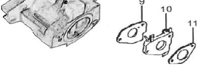
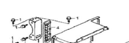
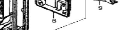
46 Ownerʼs Manual Control panel (P) 9 APA Parts No. Parts No. Description APG3560-P-01-JD JF200LPG-I-0 ELECTRO MAGNETIC VALVE SWITCH ASSY. APG3560-P-02-JD JD6500ELPG-A-01 ENGINE SWITCH ASSY. APG3560-P-03-JD JD6500BST-E-04 VOLT METER ASSY. APG3560-P-04-JD JD6500LPG-A-02 CIRCUIT BREAKER APG3560-P-05-JD JD6500BST-E V/240V RECEPTACLE (L14-30) APG3560-P-06-JD JD6500BST-E V RECEPTACLE (L5-30) APG3560-P-07-JD JD6500BST-E V RECEPTACLE (Ru-22) APG3560-P-08-JD JD6500LPG-A-03 TIME WATCH APG3560-P-09-JD JD6500BST-E-09 EARTH TERMINAL SET
 APG3560-Q-04-JD")
 APG3560-Q-07-JD JD6500LPG-B-03 COPING APG3560-Q-08-JD JD3500LPG-B-06 FIX")
47 6000W Propane Generator Frame(Q) APA Parts No. Parts No. Description APG3560-Q-01-JD JD6500ELPG-B-01 FRAME COMP. APG3560-Q-02-JD JD3800-F-05 BOTTOM RUBBER APG3560-Q-03-JD JD3800-F-04 FLANGE NUT (M8) APG3560-Q-04-JD JD6500LPG-B-02 ARC COVER APG3560-Q-05-JD JD3500LPG-C-03 FLANGE BOLT (M6X12) APG3560-Q-06-JD JD3500LPG-B-04 FLANGE NUT (M6) APG3560-Q-07-JD JD6500LPG-B-03 COPING APG3560-Q-08-JD JD3500LPG-B-06 FIX FRAME
48 Owner s Manual Rotor Stator APA Parts No. Parts No. Description APG3560-R-01-JD JD6500-D-01 STATOR COVER APG3560-R-02-JD JD6500-D-02 STATOR ASSY. APG3560-R-03-JD JD6500-G-03 COOLING FAN APG3560-R-04-JD JD3800-G-04 BRUSH ASSY. APG3560-R-05-JD JD3800-G-05 TAPPING SCREW (M5 14) APG3560-R-06-JD JD3800-G-06 RR HOUSING APG3560-R-07-JD JD3800-G-07 PAN SCREW (M5 12) APG3560-R-08-JD JD6500-G-08 FLANGE BOLT (M6x179) APG3560-R-09-JD JD6500-G-09 AUTOMATIC VOLTAGE REGULATOR ASSY. APG3560-R-10-JD JD3800-G-10 GENERATOR COVER APG3560-R-11-JD JD3800-G-11 CABLE TIE APG3560-R-12-JD JD3800-G-12 FLANGE BOLT (M5 12) APG3560-R-13-JD JD6500-D-03 ROTOR COMP. APG3560-R-14-JD JD3800-G-14 BEARING ASSY. APG3560-R-15-JD JD3800-G-15 PLAIN WASHER APG3560-R-16-JD JD6500-D-04 FLANGE BOLT (M10 265) APG3560-R-17-JD JD6500-D-05 FLANGE BOLT (M5 214) APG3560-R-18-JD JD3800-G-18 HEX.BOLT (M5 20) APG3560-R-19-JD JD3800-G-19 VOLT CHANGE TERMINAL BR-AC-W APG3560-R-20-JD JD3800-G-20 PLAIN WASHER (5mm) APG3560-R-21-JD JD3800-G-21 HEX. NUT (M5) APG3560-R-22-JD JD3800-G-22 SPRING WASHER (5mm) APG3560-R-23-JD JD3800-G-23 CRANK CASE GROMMET
Cylinder barrel (B) APA Parts No. Parts No. Description
 APA Parts No. Parts No. Description") Cylinder barrel (B) APG3560-B-01-JD JF340-B-01 FLANGE BOLT (M6 14) APG3560-B-02-JD JF240-B-02 OIL LEVEL SWITCH ASSY. APG3560-B-03-JD JF240-B-03 O-RING (14mm) APG3560-B-04-JD JF340-B-02 FLANGE NUT (M10)
Cylinder barrel (B) APG3560-B-01-JD JF340-B-01 FLANGE BOLT (M6 14) APG3560-B-02-JD JF240-B-02 OIL LEVEL SWITCH ASSY. APG3560-B-03-JD JF240-B-03 O-RING (14mm) APG3560-B-04-JD JF340-B-02 FLANGE NUT (M10)
Owner s Manual 1200 Watt Generator
 CIRCUIT BREAKER AC CIRCUIT BREAKER DC AC 120V RR7500 Owner s Manual 1200 Watt Generator PUSH TO RESET ON ENGINE SWITCH OFF PILOT Warning To Reduce The Risk Of Injury, User Must Read And Understand Instruction
GENERATOR 9 HP ROBIN RECOIL START
 Generators GENERATOR 9 HP ROBIN RECOIL START Model 90236 OPERATING INSTRUCTIONS 3491 Mission Oaks Blvd., Camarillo, CA 93011 Visit our Web site at: http://www.harborfreight.com Copyright 2003 by Harbor
GENERATOR SET 5.5 HP - RECOIL START W/2400W RATED
 Generators GENERATOR SET 5.5 HP - RECOIL START - 2200W/2400W RATED Model 91213 OPERATING INSTRUCTIONS 3491 Mission Oaks Blvd., Camarillo, CA 93011 Visit our Web site at http://www.harborfreight.com TO
10000W Generator W Generator. Battery 15. Assembly 16. Operation 17. Spark Plug Service 22. Inspection, Cleaning, Maintenance and Storage 23
 10000W Generator Topic Limited Warranty Safety Guidelines General Precautions Page 3 5 6 Battery 15 Assembly 16 Operation 17 Spark Plug Service 22 Inspection, Cleaning, Maintenance and Storage 23 Installation
Application/Equipment Rated Watts (Running) Maximum Watts (Starting) Light Bulb 75W Refrigerator/Freezer TOTALS
 Maximum Watts (Starting) Light Bulb 75W Refrigerator/Freezer TOTALS") Generator Selecting a Generator You must know the rated and maximum wattage for appliances to be used with a generator. Appliances with electric motors may require 2-3 times the rated power when starting
Generator Selecting a Generator You must know the rated and maximum wattage for appliances to be used with a generator. Appliances with electric motors may require 2-3 times the rated power when starting
OPERATING INSTRUCTIONS. Note: 6V Charging. Requires Manual Shut Off.
 Requires Manual Shut Off. 6 / 2 AMP,, DUAL RATE BATTER TTERY CHARGER 45005 OPERATING INSTRUCTIONS E224783 E224783 Note: 6V Charging Due to continuing improvements, actual product may differ slightly from
Owner s Manual Pro2 7500WATT GENERATOR
 Owner s Manual Pro2 7500WATT GENERATOR Please read and save these instructions. www.gentronusa.com Topic Page Limited Warranty 3 Safety Guidelines 5 General Precautions 6 Battery 15 Assembly 16 Operation
Limited Warranty 2. Safety Guidelines 4. General Precautions 5. Battery 11. Assembly 12. Operation 15. Inspection, Cleaning and Maintenance 19
 Table Of Contents Topic Page Limited Warranty 2 Safety Guidelines 4 General Precautions 5 Battery 11 Assembly 12 Operation 15 Inspection, Cleaning and Maintenance 19 Transporting/Storage 21 Installation
7500 Watt Generator. with Electric Start. SP-GG750E. Owner s Manual
 7500 Watt Generator with Electric Start SP-GG750E WARNING! To Reduce The Risk Of Injury, User Must Read And Understand Instruction Manual. www.steele-products.com Table Of Contents Topic Page Limited Warranty
GENERATOR SET 5.5 HP - RECOIL START W/2400W RATED. Model OPERATING INSTRUCTIONS
 GENERATOR SET 5.5 HP - RECOIL START - 2200W/2400W RATED Model 92455 OPERATING INSTRUCTIONS 3491 Mission Oaks Blvd., Camarillo, CA 93011 Visit our Web site at http://www.harborfreight.com To prevent serious
RMT1201. ORIGINAL INSTRUCTIONS Cordless Multi-Tool
 RMT1201 ORIGINAL INSTRUCTIONS Cordless Multi-Tool Important! It is essential that you read the instructions in this manual before operating this machine. Subject to technical modifications. Safety GENERAL
TWIN HALOGEN SHOP LIGHT
 TWIN HALOGEN SHOP LIGHT 36787 ASSEMBLY & OPERATING INSTRUCTIONS 3491 Mission Oaks Blvd., Camarillo, CA 93011 Visit our Web Site at www.harborfreight.com Copyright 2005 by Harbor Freight Tools. All rights
Owner s Manual ST-GP2300. WARNING! To Reduce Risk of Injury, User Must Read and Understand Owner s Manual Prior to Use.
 ST-GP2300 Owner s Manual WARNING! To Reduce Risk of Injury, User Must Read and Understand Owner s Manual Prior to Use. NOTE: Retain Original Sales Receipt as Proof of Purchase! ST-GP2300 2300W Generator
B
 5250 5250B 1-866-591-8921 5250W Generator Table of Contents Topic Page SafetyGuidelines General Gui Precautions d elines 4 General Parts Operation Inspection,CleaningandMaintenance Installation Troublesooting
4-VOLT LITHIUM-ION AUTO-LOAD SCREWDRIVER w/led WORKLIGHT
 SKU 241-1394 4-VOLT LITHIUM-ION AUTO-LOAD SCREWDRIVER w/led WORKLIGHT Operation Manual WARNING! Please read this manual before using this product. Failure to do so can result in serious injury. SAVE THIS
Hot-Shot Operating Instructions
 Hot-Shot Operating Instructions Model 400, 320, and 300 (For use with Copper and Iron Pipe) Your Hot-Shot is designed to give you years of trouble-free, profitable service. However, no machine is better
10000B
 10000 10000B 1-866-591-8921 10000W Generator Table of Contents Topic Safety Guidelines General Precautions General Parts Battery Operation Inspection, Cleaning and Maintenance Installation Troubleshooting
ECSS. Electric Chain Saw Chain Sharpener Assembly & Operating Instructions
 ECSS Electric Chain Saw Chain Sharpener Assembly & Operating Instructions READ ALL INSTRUCTIONS AND WARNINGS BEFORE USING THIS PRODUCT. SAVE THESE INSTRUCTIONS FOR FUTURE REFERENCE. This manual provides
FJC, Inc. Part # V BATTERY Charger/Maintainer INSTRUCTION MANUAL SAFETY WARNINGS AND PRECAUTION
 FJC, Inc. Part # 52020 12V BATTERY Charger/Maintainer INPUT: 110V AC 60Hz OUTPUT: 6/12V DC 2A INSTRUCTION MANUAL SAFETY WARNINGS AND PRECAUTION CAUTION: TO PREVENT BATTERY DAMAGE: DO NOT USE on gel batteries
EC DECLARATION OF CONFORMITY
 EC DECLARATION OF CONFORMITY 14 2500W INVERTER GENERATOR IM2500I CERTIFICATE OF GUARANTEE This product is guaranteed for a period of 1 Year, with effect from the date of purchase and applies only to the
4 in 1 POWER STATION Model: 7226
 Please carefully read and save these instructions before attempting to assemble, maintain, install, or operate this product. Observe all safety information to protect yourself and others. Failure to observe
ARTER AND DC POWER SOURCE
 JUMPSTAR ARTER AND DC POWER SOURCE 91045 ASSEMBLY AND OPERATING INSTRUCTIONS 3491 MISSION OAKS BLVD., CAMARILLO, CA 93011 VISIT OUR WEB SITE AT HTTP://WWW.HARBORFREIGHT.COM Copyright 2003 by Harbor Freight
original instructions 18V Torch RFP1801
 original instructions 18V Torch RFP1801 Important! It is essential that you read the instructions in this manual before operating this machine. Subject to technical modifications. Safety GENERAL POWER
APG3002. Owner s Manual 3500 WATT GENERATOR WITH MOBILITY KIT
 APG3002 TM Owner s Manual 3500 WATT GENERATOR WITH MOBILITY KIT Table of Contents 3.5KW GENERATOR Topic Page Safety Guidelines Definitions 3 General Precautions 3 Assembly 11 Specifications 13 General
Electric Chainsaw Sharpener With Bar Mount
 Electric Chainsaw Sharpener With Bar Mount Owner s Manual WARNING: Read carefully and understand all ASSEMBLY AND OPERATION INSTRUCTIONS before operating. Failure to follow the safety rules and other basic
6000W Generator. 6000W Generator. Battery 15. Assembly 16. Operation 17. Spark Plug Service 22. Inspection, Cleaning, Maintenance and Storage 23
 6000W Generator Topic Limited Warranty Safety Guidelines General Precautions Page 3 5 6 Battery 15 Assembly 16 Operation 17 Spark Plug Service 22 Inspection, Cleaning, Maintenance and Storage 23 Installation
9000W Generator. Cylinder head system assy.
 PARTS LISTING 34 Cylinder head system assy. APAPartNo. Description Part. No APG-3090-A-01-JD HEAD COVER COMP. BOLT JF340-A-01 APG-3090-A-02-JD HEAD COVER WASHER COMP. JF340-A-02 APG-3090-A-03-JD TUBE JF340-A-13
Pressure Washer Hose Reel
 Pressure Washer Hose Reel Owner s Manual WARNING: Read carefully and understand all ASSEMBLY AND OPERATION INSTRUCTIONS before operating. Failure to follow the safety rules and other basic safety precautions
1/2 HP SUMP PUMP OWNER'S MANUAL
 TM 1/2 HP SUMP PUMP OWNER'S MANUAL WARNING: Read carefully and understand all INSTRUCTIONS before operating. Failure to follow the safety rules and other basic safety precautions may result in serious
440/880LB ELECTRIC HOIST STF-4488EH
 ELECTRIC HOIST 440/880LB WARNING: Read carefully and understand all ASSEMBLY AND OPERATION INSTRUCTIONS before operating. Failure to follow the safety rules and other basic safety precautions may result
Owner s Manual PARTS LISTING
 Owner s Manual PARTS LISTING 35 Cylinder head system assy. SP-GG350-A-01-JD CYLINDER HEAD COMP. JF200-A-01 SP-GG350-A-02-JD EX. VALVE GUIDE JF168-A-02 SP-GG350-A-03-JD IN. VALVE GUIDE JF168-A-03 SP-GG350-A-04-JD
Hydraulic Bead Breaker Kit
 Hydraulic Bead Breaker Kit Owner s Manual WARNING: Read carefully and understand all ASSEMBLY AND OPERATION INSTRUCTIONS before operating. Failure to follow the safety rules and other basic safety precautions
POWER INVERTER 1,000 WATT / 2,000 WATT PEAK
 POWER INVERTER 1,000 WATT / 2,000 WATT PEAK 94009 ASSEMBLY AND OPERATING INSTRUCTIONS 3491 Mission Oaks Blvd., Camarillo, CA 93011 Visit our Web site at http://www.harborfreight.com TO PREVENT SERIOUS
POWER INVERTER 700 WATT / 1800 WATT PEAK
 POWER INVERTER 700 WATT / 1800 WATT PEAK 91848 ASSEMBLY AND OPERATING INSTRUCTIONS 3491 Mission Oaks Blvd., Camarillo, CA 93011 Visit our Web site at http://www.harborfreight.com TO PREVENT SERIOUS INJURY,
Large Hydraulic Bead Breaker
 Large Hydraulic Bead Breaker Owner s Manual WARNING: Read carefully and understand all ASSEMBLY AND OPERATION INSTRUCTIONS before operating. Failure to follow the safety rules and other basic safety precautions
E-DRIV MD-Series DC Torque Control System Calibration Procedure
 Revision: 1.1 July 05, 2017 E-DRIV MD-Series DC Torque Control System Calibration Procedure www.mountztorque.com 1080 N 11 th St - San Jose CA 95112-408.292.2214 1 GENERAL SAFETY RULES WARNING! Read and
60 Watt Industrial LED Low Bay Light
 60 Watt Industrial LED Low Bay Light Owner s Manual WARNING: Read carefully and understand all ASSEMBLY AND OPERATION INSTRUCTIONS before operating. Failure to follow the safety rules and other basic safety
Adjustable Steel Welding Table
 Adjustable Steel Welding Table Owner s Manual WARNING: Read carefully and understand all ASSEMBLY AND OPERATION INSTRUCTIONS before operating. Failure to follow the safety rules and other basic safety
Owner s Manual. Parts List. Cylinder Head assy. APA Part No. Description Part. No
 Cylinder Head assy. A SP-GG900E-A-01-JD HEAD COVER COMP. BOLT JF340-A-01 SP-GG900E-A-02-JD HEAD COVER WASHER COMP. JF340-A-02 SP-GG900E-A-03-JD TUBE JF340-A-13 SP-GG900E-A-04-JD HEAD COVER COMP. JF340-A-04
SeekTech Inductive Clamp
 Inductive Clamp Manual SeekTech Inductive Clamp! Read this Operator s Manual carefully before using this tool. Failure to understand and follow the contents of this manual may result in electrical shock,
RPS1215 ORIGINAL INSTRUCTIONS. Cordless Pruner
 RPS5 ORIGINAL INSTRUCTIONS Cordless Pruner Important! It is essential that you read the instructions in this manual before assembling, operating and maintaining the product. Subject to technical modification.
CORDLESS IMPACT WRENCH
 CORDLESS IMPACT WRENCH 1/2 DRIVE - 19.2 VOLT Model 92798 OPERATING INSTRUCTIONS 3491 Mission Oaks Blvd., Camarillo, CA 93011 Visit our Web site at: http://www.harborfreight.com TO PREVENT SERIOUS INJURY,
1200W CaR PoliSheR en RS4900
 1200W Car Polisher RS4900 RS4900 8 1 2 7 3 4 5 6 A B flat nozzle C D E F 1200W Car Polisher RS4900 G H flat nozzle I J K L 4 1200W Car Polisher COMPONT LIST 1 2 3 4 5 6 7 Variable speed control Switch
10000W Generator W Generator. Battery 15. Assembly 16. Operation 17. Spark Plug Service 22. Inspection, Cleaning, Maintenance and Storage 23
 Topic Limited Warranty Safety Guidelines General Precautions Page 5 6 Battery 5 Assembly 6 Operation 7 Spark Plug Service 22 Inspection, Cleaning, Maintenance and Storage 2 Installation 29 Compliance Speci
SAFETY AND OPERATING MANUAL. Lithium-Ion cordless hammer drill WX372 WX372.1 WX372.9
 SAFETY AND OPERATING MANUAL 2 Original Instructions General Power Tool Safety Warnings WARNING: Read all safety warnings and all instructions. Failure to follow the warnings and instructions may result
EJ212 Electric Jack 1 Ton (2,000 lbs) Assembly & Operating Instructions
 Assembly & Operating Instructions") EJ212 Electric Jack 1 Ton (2,000 lbs) Assembly & Operating Instructions READ ALL INSTRUCTIONS AND WARNINGS BEFORE USING THIS PRODUCT. This manual provides important information on proper operation & maintenance.
EJ212 Electric Jack 1 Ton (2,000 lbs) Assembly & Operating Instructions READ ALL INSTRUCTIONS AND WARNINGS BEFORE USING THIS PRODUCT. This manual provides important information on proper operation & maintenance.
Sawhorse with Chainsaw Holder
 Sawhorse with Chainsaw Holder Owner s Manual Chainsaw not included. WARNING: Read carefully and understand all ASSEMBLY AND OPERATION INSTRUCTIONS before operating. Failure to follow the safety rules and
SUBMERSIBLE PUMP. Model ASSEMBLY AND OPERATING INSTRUCTIONS
 SUBMERSIBLE PUMP Model 37952 ASSEMBLY AND OPERATING INSTRUCTIONS 3491 Mission Oaks Blvd., Camarillo, CA 93011 Visit our Web site at: http://www.harborfreight.com Copyright 2003 by Harbor Freight Tools.
Air-Operated Waste Oil Drainer
 Air-Operated Waste Oil Drainer 20-Gallon Tank Owner s Manual WARNING: Read carefully and understand all ASSEMBLY AND OPERATION INSTRUCTIONS before operating. Failure to follow the safety rules and other
BENCH GRINDER MODEL NO. OZBG150WA
 BENCH GRINDER 150mm MODEL NO. OZBG150WA OPERATING INSTRUCTIONS To view our entire range visit www.ozito.com.au SPECIFICATIONS MODEL NO. OZBG150WA Input Power: 150W Input Voltage: 230V ~ 50Hz No Load Speed:
3oweramenca.com
 www.all 3oweramenca.com 3250W Generator Table of Contents Topic Page Limited Warrant 3 Safety Guidelines 5 General Precautions 6 B att ery 15 Assembly 16 Operation 17 Ins ection, Cleanin and Maintenance
SBC12 H Operating instructions Mode d emploi Manual de instrucciones
 *254901* 254901 SBC12 H Operating instructions Mode d emploi Manual de instrucciones Safety Precautions Read all Instructions GENERAL SAFETY RULES FOR ALL BATTERY OPERATED TOOLS WARNING! Read and understand
7500W Generator. 7500W Generator. 7500W Generator. 7500W Generator. Cylinder barrel. Cylinder head system assy.
 Cylinder head system assy. Cylinder barrel APG0-A-0-JD HEAD COVER COMP. BOLT APG0-A-02-JD HEAD COVER WASHER COMP APG0-A-0-JD WASHER COVER PACKING APG0-A-0-JD HEAD COVER COMP APG0-A-0-JD HEAD COVER PACKING
Disc Grinder Model G 18MR G 23MR G 23MRU
 Disc Grinder Model G 18MR G 23MR G 23MRU Handling instructions G23MR NOTE: Before using this Electric Power Tool, carefully read through these HANDLING INSTRUCTIONS to ensure efficient, safe operation.
INSTRUCTION MANUAL ANGLE GRINDER PT W
 INSTRUCTION MANUAL ANGLE GRINDER PT50360 4½ INCHES 120V 60Hz 600W 5A 12,000 rpm C US Note : Before operating this tool, read this manual and follow all safety rules and operating instructions. This electric
50 Ft. Retractable Cord Reel
 50 Ft. Retractable Cord Reel with Triple Tap Owner s Manual WARNING: Read carefully and understand all ASSEMBLY AND OPERATION INSTRUCTIONS before operating. Failure to follow the safety rules and other
ELECTRIC HYDRAULIC GEAR PUMP
 ELECTRIC HYDRAULIC GEAR PUMP 46169 ASSEMBLY AND OPERATING INSTRUCTIONS 3491 Mission Oaks Blvd., Camarillo, CA 93011 Visit our Web site at http://www.harborfreight.com Copyright 2001 by Harbor Freight Tools.
Specifications. Important Safety Information
 Specifications Gauge Range 0-30 IN. of mercury (in Hg) 0-760 torr Important Safety Information WARNING! READ AND UNDERSTAND ALL INSTRUCTIONS Failure to follow instructions listed below may result in serious
Model: SPTOGT01 TRACTOR PTO GENERATOR
 www.scintex.com.au sales@scintex.com.au Model: SPTOGT01 TRACTOR PTO GENERATOR SET UP, OPERATING, AND SERVICING INSTRUCTIONS Read this material before using this product. Failure to do so can result in
Angle Grinder Holder
 Angle Grinder Holder Owner s Manual WARNING: Read carefully and understand all ASSEMBLY AND OPERATION INSTRUCTIONS before operating. Failure to follow the safety rules and other basic safety precautions
MINI AIR ANGLE DIE GRINDER
 MINI AIR ANGLE DIE GRINDER Model 33171 ASSEMBLY AND OPERATING INSTRUCTIONS Due to continuing improvements, actual product may differ slightly from the product described herein. 3491 Mission Oaks Blvd.,
TABLE OF CONTENTS. Section 1 - Important Safety Instructions Section 2 - Grounding Instructions Section 3 - Operator Cautions...
 Light Tools - DC Screwdriver Operation & Maintenance Manual For Models: SKD-2000L/UL/B, SKD-2200L/UL/B, SKD-2300L/UL/B SKD-5200L/UL/B, SKD-5200P/UL/B SKD-5300L/UL/B, SKD-5300P/UL/B Dixon Automatic Tool
BUFFER/POLISHER SYSTEM
 Owner s Manual Double Insulated BUFFER/POLISHER SYSTEM Model No. 646.10729 NRTL CAUTION: Read and follow all safety rules and operating instructions before first use of this product. Safety Rules Operation
WR 22SE WR 25SE WR25SE. Handling instructions
 WR 22SE WR 25SE WR25SE Handling instructions GENERAL POWER TOOL SAFETY WARNINGS WARNING Read all safety warnings and all instructions. Failure to follow the warnings and instructions may result in electric
110 Volt/12 Volt Portable Inflator
 110 Volt/12 Volt Portable Inflator Owner s Manual WARNING: Read carefully and understand all ASSEMBLY AND OPERATION INSTRUCTIONS before operating. Failure to follow the safety rules and other basic safety
VICE MOUNTED BEAD ROLLER
 VICE MOUNTED BEAD ROLLER Owner s Manual WARNING: Read carefully and understand all ASSEMBLY AND OPERATION INSTRUCTIONS before operating. Failure to follow the safety rules and other basic safety precautions
Model TC-20. Tube Cut-Off Machine. Operator s Manual REV H
 Model TC-20 Tube Cut-Off Machine Operator s Manual 90-2333 REV H Scientific Systems, Inc. 349 N. Science Park Road State College, PA 16803 www.ssihplc.com Phone: 800-441-4752 Fax: 814-238-7532 Email: sales@ssihplc.com
Manual Tire Changing Station
 Manual Tire Changing Station Owner s Manual WARNING: Read carefully and understand all ASSEMBLY AND OPERATION INSTRUCTIONS before operating. Failure to follow the safety rules and other basic safety precautions
12 Volt Heavy-Duty Air Inflator
 12 Volt Heavy-Duty Air Inflator Owner s Manual WARNING: Read carefully and understand all ASSEMBLY AND OPERATION INSTRUCTIONS before operating. Failure to follow the safety rules and other basic safety
40 V HEDGE TRIMMER ATTACH YOUR RECEIPT HERE
 ITEM #0796788 40 V HEDGE TRIMMER MODEL #KHT 240-07 Español p. 17 ATTACH YOUR RECEIPT HERE Serial Number Purchase Date Questions, problems, missing parts? Before returning to your retailer, call our customer
EIGHT GALLON PSI AIR COMPRESSOR
 EIGHT GALLON - 115 PSI AIR COMPRESSOR Model 95370 Assembly And Operation Instructions Due to continuing improvements, actual product may differ slightly from the product described herein. 3491 Mission
PREFACE. This manual will explain how to operate and service your generator set.
 PREFACE Thank you for purchasing products from SYCAMORE SCS, LLC. We appreciate your business. The following manual is only a guide to assist you and is not a complete or comprehensive manual of all aspects
Compressor Duty Motor - 1 HP. Model 40132
 Compressor Duty Motor - 1 HP Model 40132 Assembly and Operating Instructions 3491 Mission Oaks Blvd., Camarillo, CA 93011 Visit our web site at http://www.harborfreight.com Copyright 2002 by Harbor Freight
4V LITHIUM-ION SCREWDRIVER OWNER S OPERATING MANUAL
 CSD-4107BG 4V LITHIUM-ION SCREWDRIVER OWNER S OPERATING MANUAL Your screwdriver has been engineered and manufactured to our high standard for dependability, ease of operation, and operator safety. When
Heavy-Duty Welding Fabrication Table
 Heavy-Duty Welding Fabrication Table with Fix-Up Kit Owner s Manual WARNING: Read carefully and understand all ASSEMBLY AND OPERATION INSTRUCTIONS before operating. Failure to follow the safety rules and
1200W Paint DRYING Lamp
 1200W Paint DRYING Lamp Model 97641 Assembly And Operation Instructions Diagrams within this manual may not be drawn proportionally. Due to continuing improvements, actual product may differ slightly from
eclipse Instruction Manual 4.0V Li-Ion Screwdriver Part #:
 eclipse Instruction Manual 4.0V Li-Ion Screwdriver Part #: 902-588 Test Equipment Depot - 800.517.8431-99 Washington Street Melrose, MA 02176 TestEquipmentDepot.com Test Equipment Depot - 800.517.8431-99
6000W Generator. 6000W Generator. 6000W Generator. 6000W Generator. Cylinder barrel. Cylinder head system assy. Description. APA Part No.
 Cylinder head system assy. Cylinder barrel A APA Part No. B APGG000-A-0-JD HEAD COVER COMP. APGG000-B-0-JD (MX ) APGG000-A-0-JD HEAD COVER WASHER COMP. APGG000-B-0-JD OIL LEVEL SWITCH ASSY. APGG000-A-0-JD
3-Pt. Quick Hitch. Owner s Manual
 3-Pt. Quick Hitch Owner s Manual WARNING: Read carefully and understand all ASSEMBLY AND OPERATION INSTRUCTIONS before operating. Failure to follow the safety rules and other basic safety precautions may
Push Trolley. Owner s Manual
 Push Trolley Owner s Manual WARNING: Read carefully and understand all ASSEMBLY AND OPERATION INSTRUCTIONS before operating. Failure to follow the safety rules and other basic safety precautions may result
18V RECIPROCATING SAW
 V RECIPROCATING SAW 93830 ASSEMBLY AND OPERATING INSTRUCTIONS Due to continuing improvements, actual product may differ slightly from the product described herein. 349 Mission Oaks Blvd., Camarillo, CA
SPECIFICATIONS GENERAL SAFETY RULES PERSONAL SAFETY. Save This Manual TOOL USE AND CARE WORK AREA
 SPECIFICATIONS 2 Forged Safety Latch Hooks Cable extends to: 44 Drop forged steel hanging bracket Heavy duty 3/16 Steel Cable Pulling Capacity: 1200 LB. One piece double ratchet gear Save This Manual You
ELECTRIC ENGRAVER 15W WARRANTY INSTRUCTION MANUAL SPECIFICATIONS WHAT S IN THE BOX. ozito.com.au. Electric Engraver
 IN ORDER TO MAKE A CLAIM UNDER THIS WARRANTY YOU MUST RETURN THE PRODUCT TO YOUR NEAREST BUNNINGS WAREHOUSE WITH YOUR BUNNINGS REGISTER RECEIPT. PRIOR TO RETURNING YOUR PRODUCT FOR WARRANTY PLEASE TELEPHONE
SIP Direct Drive Oil-Lube Air Compressors - Operating & Maintenance Instructions
 SIP Direct Drive Oil-Lube Air Compressors - Operating & Maintenance Instructions Please read and fully understand the instructions in this manual before operation. Keep this manual safe for future reference.
SAVE THESE INSTRUCTIONS
 12 Volt High-V Volume Air Inflator Owner s Manual WARNING: Read carefully and understand all ASSEMBLY AND A OPERATION INSTRUCTIONS before operating. Failure to follow the safety rules and other basic safety
Digital Auto Multi-Tester
 Digital Auto Multi-Tester 95625 ASSEMBLY AND OPERATING INSTRUCTIONS Due to continuing improvements, actual product may differ slightly from the product described herein. 349 Mission Oaks Blvd., Camarillo,
Disc Grinder Model G 18SCY G 18SEY G 18UBY G 23SCY G 23SEY G 23UBY
 Disc Grinder Model G 18SCY G 18SEY G 18UBY G 23SCY G 23SEY G 23UBY Handling instructions G23SEY NOTE: Before using this Electric Power Tool, carefully read through these HANDLING INSTRUCTIONS to ensure
Click Here To View Item at
 Click Here To View Item at www.gappower.com Operating Instructions Model 320 (For use with Copper and Iron Pipe) Your Hot-Shot is designed to give you years of trouble-free, profitable service. However,
ORIGINAL INSTRUCTIONS
 OPERATION & MAINTENANCE INSTRUCTIONS CBB200 Shown here BUFFER/POLISHER MODEL NO: CBB150, CBB200 PART NO: 6500485, 6500490 ORIGINAL INSTRUCTIONS LS0818 - ISS 1 INTRODUCTION Thank you for purchasing this
Manual Chain Hoist. Owner s Manual
 Manual Chain Hoist Owner s Manual WARNING: Read carefully and understand all ASSEMBLY AND OPERATION INSTRUCTIONS before operating. Failure to follow the safety rules and other basic safety precautions
3500 T E GENERATOR SP-6L350. runsenvlcetrill: S88t. PARA SERVlCIO LLAHE: CERTiFiED TO CAN/CSA C22.2 NO. "I00
 0wner's Manual 3500 T E GENERATOR 3108307 CERTiFiED TO CAN/CSA C22.2 NO. "I00 SP-6L350 runsenvlcetrill: 888-896-S88t PARA SERVlCIO LLAHE: 3500W to Table of Contents Topic Page Limited Warrant 3 Safety
12V Oil Extractor Pump
 12V Oil Extractor Pump Owner s Manual WARNING: Read carefully and understand all ASSEMBLY AND OPERATION INSTRUCTIONS before operating. Failure to follow the safety rules and other basic safety precautions
Welding Clips. Model Due to continuing improvements, actual product may differ slightly from the product described herein.
 Welding Clips Model 95637 Assembly And Operation Instructions Due to continuing improvements, actual product may differ slightly from the product described herein. 3491 Mission Oaks Blvd., Camarillo, CA
ELECTRIC CAR POLISHER
 ELECTRIC CAR POLISHER MODEL NO: CP254 PART NO: 6462108 OPERATION & MAINTENANCE INSTRUCTIONS LS0610 INTRODUCTION Thank you for purchasing this CLARKE electric car polisher. Before attempting to use this
AIR PAINT SHAKER OWNER'S MANUAL
 AIR PAINT SHAKER OWNER'S MANUAL WARNING: Read carefully and understand all INSTRUCTIONS before operating. Failure to follow the safety rules and other basic safety precautions may result in serious personal
2000WGenerator. 7500WGenerator. Topic Page. SafetyGuidelines 3. Precautions elines. General. recautions 12. Inspection,CleaningandMaintenance.
 2000 2000 2000WGenerator 7500WGenerator Topic Page SafetyGuidelines 3 General agui Precautions elines d 4 General lparts recautions 12 Battery Operation 13 Assembl Inspection,CleaningandMaintenance 19
PREFACE. This manual will explain how to operate and service your generator set.
 PREFACE Thank you for purchasing products from SYCAMORE SCS, LLC. We appreciate your business. The following manual is only a guide to assist you and is not a complete or comprehensive manual of all aspects
Battery 15. Assembly 16. Operation 17. Spark Plug Service 22. Inspection, Cleaning, Maintenance and Storage 23. Installation 29.
 Topic Limited Warranty Safety Guidelines General Precautions Page 3 5 6 Battery 15 Assembly 16 Operation 17 Spark Plug Service 22 Inspection, Cleaning, Maintenance and Storage 23 Installation 29 Compliance
8 Inch Benchtop Buffer
 8 Inch Benchtop Buffer Owner s Manual WARNING: Read carefully and understand all ASSEMBLY AND OPERATION INSTRUCTIONS before operating. Failure to follow the safety rules and other basic safety precautions