APOLLO SOLAR. TurboCharger T80 Installation and Operation Manual. T80 Installation and Operation Manual
|
|
|
- Caitlin Hopkins
- 5 years ago
- Views:
Transcription


1 APOLLO SOLAR TurboCharger T80 Installation and Operation Manual T80 Installation and Operation Manual
2 TurboCharger T80 Installation and Operation Manual Page 1 TABLE OF CONTENTS Revision History...2 Important Safety Instructions...3 Overview...4 Planning Your System...4 Loads...4 Determining Battery Voltage...4 Determining PV Array Voltage...5 Maximum Voc...5 Conversion Efficiency...6 Wire Sizing...6 Determining Maximum Current...7 Circuit Protection...7 Lightning Protection...8 Installing the T Initializing the T Front Panel LED Status Indicator...15 Restarting the T Operating the T Status Screens...17 Data Screens...18 Setup...19 Setup Selections Screen...20 Main EQ Setup Screen...20 Main Miscellaneous Setup Screen...22 Aux Relay Setup Screen...25 Emonitor Setup Screen...29 T80 Wiring Diagram with Batteries...30 Warranty Information...31 Appendix A Wire Sizing Table for 1.5% Voltage Drop...32 Appendix B Bootloader Function...36
3 TurboCharger T80 Installation and Operation Manual Page 2 Revision History Manual Revision Applies to Firmware Revision Date BY /12/06 KMV , 4.00, /24/07 KMV , 4.00, 4.03, 4.04, /29/07 KMV /16/07 KMV /23/07 KMV
4 TurboCharger T80 Installation and Operation Manual Page 3 IMPORTANT SAFETY INSTRUCTIONS SAVE THESE INSTRUCTIONS The TurboCharger T80 is capable of processing over 4.8 kw of DC power. These Safety Instructions are to ensure safe installation and operation of the T80 and the equipment it is connected to. Be sure to read the instructions which came with the T80 and all other connected equipment carefully. Inspect the T80 and all other equipment and read all cautionary and instructive markings on all equipment. Be sure to follow all cautions and instructions when installing all equipment. Save this manual, it has important maintenance and operation information. The T80 Battery System Controller is designed to be permanently connected to a DC electrical system. The T80 must be provided with an equipment-grounding conductor connected to the DC input ground. THIS IS THE SYMBOL FOR GROUND: Use a minimum of #8 AWG conductors rated for at least 75º C. The input/output and ground terminals on the T80 will accept #8 to #3 AWG wire. The lugs are rated to accept a single conductor. Torque all connections to 50 lb-in (5.65 N-m) Apollo Solar recommends that all wiring be done by an electrician or certified technician in accordance to all local and national electrical codes applicable in your jurisdiction. Do not perform electrical work you do not feel qualified to do. To avoid a risk of fire and electric shock, make sure that existing wiring is in good condition and that wire is not undersized. Do not operate the T80 or any other system components with damaged or substandard wiring. Use only attachments recommended or sold by Apollo Solar or our Authorized Distribution Partners, doing otherwise may result in a risk of fire, electric shock, or injury to persons. To reduce the risk of electrical shock, disconnect all sources of DC power from the T80 before attempting any maintenance or cleaning or working on any components connected to the controller. INTENDED USE The T80 is designed to charge lead acid batteries of flooded, gel and AGM chemistries from 12 to 48 Vdc nominal. For all other battery types follow specific voltage, current, and time settings provided by the manufacturer of the batteries. WARNING Do not expose this unit to rain, snow, or liquids of any type. The T80 is designed for indoor use only. Damp environments will significantly shorten the life of this product and installation in damp environments may affect the product warranty. (For information about damp environment warranty exclusions see the Warranty section at the end of this manual). Do not operate the T80 if it has been damaged in any way. If the unit is damaged follow the product return directions in the Warranty section at the end of this manual. Do not disassemble the T80.The T80 does not have any user-serviceable parts. Internal capacitors remain charged after all power is disconnected and attempting to service the unit may result in a risk of electrical shock or fire. Always use insulated tools to reduce the chance of short-circuits when installing or working with the T80, the batteries, PV arrays and any other connected equipment. To further reduce the risk of exposure to live circuits remove all jewelry while installing this system. EXPLOSIVE GAS PRECAUTIONS Working in the vicinity of lead acid batteries is dangerous. Batteries generate explosive gases during normal operation. Follow all Explosive Gas Safety procedures. To reduce the risk of battery explosion, follow these instructions and those published by the battery manufacturer and supplier.
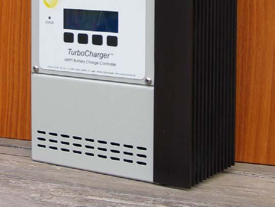
5 TurboCharger T80 Installation and Operation Manual Page 4 OVERVIEW The TurboCharger T80 is essentially a smart DC to DC converter which has been optimized to harvest maximum energy from the PV array in battery based solar electric systems by using a variety of maximum power point tracking (MPPT) strategies. The controller s secondary objective is to ensure that the batteries receive a full charge without becoming overcharged. This is accomplished through a five stage charging process. Built into the T80 is a comprehensive data logging system which tracks battery state of charge (SOC) and power produced by the PV array. The DC to DC converter feature of the T80 allows for a wide variety of input and battery voltage configurations. Batteries may be configured from 12 to 48 Vdc nominal (12, 24, 36, and 48 are the factory default settings). PV arrays may be wired in up to 72 Vdc nominal, with the actual constraint being the maximum allowable Voc at worse case conditions, 150 Voc. (The T80 automatically shuts down above 140 Voc.) This feature allows system designers considerable flexibility with respect to wire sizing and module location. This controller may be used in hybrid systems which have PV and wind or micro hydro generators. In these systems the auxiliary relays are utilized to control dump loads. These relays have a host of other control uses and functions and can be custom programmed to suit the system operator s needs. Please carefully read the Planning Your System section of this manual and all warnings before beginning installation of your T80. To ensure best performance of the T80 follow all installation instructions and wiring guidelines. Always install equipment in accordance to local codes and bylaws. We recommend that external lightning protection be installed along with the T80. Loads PLANNING YOUR SYSTEM Congratulations on choosing a solar electric system, when well installed and planned it should give you decades of service life. The T80 is a key component in your PV system. From a system planners perspective the T80 is very flexible with its ability to accept a wide range of input voltages and produce a similarly wide range of output voltages. Never the less some planning and choice is required when deciding on the components and configuration of your PV system. The first step in planning a PV system is to know something about the load. What is the power intended for? How much power will be required? There are many resources available in print and on-line to help determine average and peak load requirements we recommend using these resources to calculate anticipated load requirements. We also recommend that planners design for load growth. Experience has shown that loads rarely remain static and are reduced even less frequently. Once the load characteristics are determined the system planner may move to make decisions about the appropriate battery voltage. Determining Battery Voltage A major factor in making this decision is how much power will be required from the batteries. As power demands increase it is advisable to raise the battery voltage. A limiting factor in system design is current it is expensive to move and provide circuit protection for large amounts of current (amps). A basic rule of electricity states current = power/voltage. This means that the higher the battery voltage the lower the current will be for any given load. For example a 96 watt load at 12 Volts draws 8 amps the same load at 48 Volts draws only 2 amps of current.
6 TurboCharger T80 Installation and Operation Manual Page 5 The table below shows rule-of-thumb recommendations for battery system voltage choices and maximum inverter sizes. Load in kwh per day Battery Voltage Suggested Inverter Size Under 2 kwh per day 12 Vdc Up to 2.5 kw 2 to 6 kwh per day 24 Vdc 2-4 kw Over 6 kwh per day 48 Vdc 3 kw and larger Other factors in making this decision will include the size of the inverter. A final factor in this decision is how much power will be required from the PV array. The T80 is designed to produce 80 amps of output current. The amount of power this represents will be dependent on the output voltage (battery bank voltage). At 12 Vdc output 80 amps is 1600 watts of power, at 48 Vdc output 80 amps is 4800 watts of power. The example above demonstrates that the amount of current or input power the T80 will accept is limited by the system battery voltage. Determining PV Array Voltage One of the great advantages of the DC to DC converter design of the T80 is that PV array voltages are no longer dictated by the battery voltage. Sizing a PV array for the T80 is much like sizing a grid tie inverter, the same questions apply: What is the max and min Vmp and Voc of each string, how many strings will I need. Maximum Voc The maximum operating voltage of the T80 is 140 Vdc. Above this, the unit will shut down to avoid damage. The absolute maximum applied input voltage the controller can accept without damage which is 150 Vdc. Each PV module has specific ratings for voltage and current at standard test conditions and temperatures, the manufacturers also publish current and temperature coefficients. The Voc for any PV module increases in cold temperatures. Modules are rated with an assumed cell temperature of 25 o C, when calculated at 0 o C there may be as much as a 25% increase in the rated Voc. The Voc voltage temperature coefficient for the specific location of the installation must be calculated from known weather data. Once the maximum Voc of the module is found a series string voltage may be determined. WARNING The Voc maximum on the coldest brightest day of the year must not exceed 150 Vdc. Input voltage in excess of 150 Vdc will result in internal damage which is NOT covered by warranty. We recommend a maximum design Voc of 140 Vdc. This will result in the most effective energy harvest.
7 TurboCharger T80 Installation and Operation Manual Page 6 Conversion Efficiency The conversion efficiency of the T80 in the proposed configuration must be considered. While it is possible to input 72 Vdc and output 12 Vdc, it is not the most efficient configuration for the controller. A system which had 36 Vdc input and 12 Vdc output would run more efficiently from the T80 s perspective. The most efficient configuration for the T80 is with 60 Vdc input and 48 Vdc output. Never-the-less, in many cases the savings in wire costs and the slight advantage of earlier wake up and shut down make the inefficient higher voltage to low voltage conversion the best system choice. Many systems input 72 Vdc for 24 and 48 Vdc batteries. The table below shows some recommended input to output configurations. Wire Sizing Battery Voltage Array Vmp Range 12 Vdc Vdc 24 Vdc Vdc 48 Vdc Vdc* * Never exceed 140 Voc in any system design. The distance between the PV array and the controller will be a factor in choosing an optimum string voltage for the T80. The higher the input voltage the smaller the wire can be for any given amount of power. For example a system with a 12 volt battery and a PV array consisting of four 6.5 amp 12 Vdc nominal modules located at a distance of 40 from the batteries could have the modules wired in series, parallel or series and parallel. Input configuration possibilities for the T80 in this example are 12, 24, and 48 Vdc. If the array was configured with the modules wired in parallel the input voltage would be 12 Vdc with an input current of 26 A. The same array wired in series would have an input voltage of 48 Vdc and an input current of 6.5 amps. In this example #1, the 26 amp 12 Vdc array #1/0 wire, which is prohibitively expensive, would be required to limit voltage drop to 2% which is recommended for 12 Vdc systems. The same array wired for 48 Vdc would only require a #8 wire. With the #8 wire the 12 Vdc array would have to be within 7 of the batteries. The distance that #8 cable can be used is over five times greater at 48 Vdc than 12 Vdc. (Refer to Wire Sizing Table for 2% Voltage Drop Appendix A) Of course, a final determining factor will be the number of modules available for installation. For example the optimum system design might call for six 12 V nominal modules in series, but the actual system to be installed consists of only 10 modules. It is not possible to wire strings of differing voltages to the T80; therefore the number of modules available must be divided into even numbers. In the example given above each string would consist of 5 modules for a nominal voltage of 60 Vdc. The above noted system could be expanded by adding one module to each string for a nominal voltage of 72 Vdc or by adding an additional string of 5 modules and maintaining the 60 Vdc nominal input voltage.
8 TurboCharger T80 Installation and Operation Manual Page 7 Determining Maximum Current The T80 is designed to handle a maximum input current of 70 amps and a maximum output current of 80 amps both of these ratings are continuous at 40 0 C. The T80 input voltage will be higher than output voltage hence input current (amps) will be lower than output current. For example twelve 6.5 amp 12 Vdc nominal PV modules wired in series and parallel to produce 36 Vdc would equate to an input current of 26 amps the rated current of each string times 4. (In series wiring the voltage increases and the current remains constant.) The output current of the controller will be dependent on the voltage of the battery bank. If the array in this example was connected to a 12 Vdc battery system the output current would be 78 amps. (Current in x V nom / V Bat = Current out). When calculating the maximum input or output current, remember to add 25% to the rated current of the PV array, this is the NEC required headroom to account for the PV s ability to produce more than the rated output under some conditions. Circuit Protection All electrical circuits require protection from over current and shorts and the T80 is no exception. The T80 should be installed with a circuit breaker or a fused disconnect on the input and output. The T80 has a maximum current limit of 80 amps on the output. It is designed and listed to run at its maximum rating continuously. The continuous rating of the T80 does not reflect the 80% derating required by the NEC for conductors, fuses, and many circuit breakers. The NEC requires that the output conductors have an amperage capacity of 1.25 X the rated current after all temperature and fill corrections are calculated. For the T80 this means conductors must be rated to carry 100 amps. The minimum cable necessary to carry the full rated output of the T80 is #3AWG, corrections for conduit fill and temperature could result in a large wire size being necessary. PV input circuits require a double correction factor for over current so PV Isc (short circuit current) must be multiplied by All PV input wires must be sized accordingly. This apparent over sizing is done to reflect the fact that solar modules can, and often do, produce more than their rated power in conditions of heightened insolation and cold temperatures. Any PV input disconnect or circuit breaker must also be rated at 1.56 of array Isc. For the T80 the maximum allowable PV array according to the NEC would have an Isc of 56 amps. The circuit would require a 90 amp input breaker. In summary Apollo Solar recommends that the input breaker be 90 amps rated for 125 Vdc and the output breaker be 100 amps rated at a minimum of 80 Vdc. Apollo Solar and it s distribution partners offer 90 and 100 amp breakers which are compatible with widely available PV system DC service entrance enclosures.
9 TurboCharger T80 Installation and Operation Manual Page 8 Wiring Diagram for T80 The simplified single-line drawing below shows the appropriate location and amperage capacity rating of circuit breakers. Please note that all circuit protection devices must be installed inside UL recognized enclosures. Follow all applicable electrical codes. Use #3 to #8 AWG wire rated for 75º C for Battery, PV and Ground connections. Torque all terminals to 50 lb-in (5.64 N-m). T80 BASIC SYSTEM WIRING DIAGRAM Input from PV Array or Combiner Box GND + _ Apollo Solar The Aux Relay screw terminals accept #14 to 22 AWG wire. Torque all signal terminals to 4.4 lbin (0.5 N-m). Only use circuit protection equipment which is DC rated for the appropriate amperage capacity and DC voltage. MODULAR CABLE WITH 3 TWISTED PAIRS. FOR CURRENT SHUNT, BATTERY VOLTAGE SENSE AND BATTERY TEMPERATURE. USE SEPARATE CONDUIT AND KEEP CLEAR OF HIGH VOLTAGE WIRING. + _ T TAB + T80 TurboCharger +BAT+ -BAT- -PV- +PV+ 90 AMP DC RATED BREAKER AMP DC RATED BREAKER SYSTEM EARTH GROUND + +Bat FUSE _ -Bat Temp SHUNT 50mV 500AMP TEMPERATURE SENSOR BATTERY VOLTAGE SENSE WIRES APOLLO SHUNT BOARD Lightning Protection Like any other electronic device the T80 may be damaged during lightning storms. We strongly recommend that external lightning protection devices be included as part of the circuit protection equipment.
10 TurboCharger T80 Installation and Operation Manual Page 9 Controller INSTALLING THE T80 To minimize voltage drop and keep wiring and circuit protection costs down the T80 should be located as close to the batteries as possible while still maintaining suitable distance to prevent any risk of fire from sparks and battery gasses. The minimum distance between the T80 and batteries should be 4 (1.2 meters). The T80 has one external mounting tab on top and four mounting screw locations in the wiring access area. Use #10 wood screws of sufficient length to penetrate ¾ into framing members or other solid wood materials. Screw locations are: Top Center of T80 (external) and inside wire access area. Locate the T80 and install the top mounting screw first, remove wiring access cover and install the remaining mounting screws. Most installations will utilize conduit to house the wires entering and leaving T80. The T80 is designed to accept conduit between ½ and 1 ¼ inches. Follow all applicable codes and regulations when installing the T80. Once securely mounted with all conduit installed the T80 is ready for wiring. Before attempting any wiring make sure that all disconnects (or circuit breakers) for the PV array and batteries are in the OFF position. IMPORTANT Keep all breakers in the OFF position until ready to initiate the T80. When you are ready to start the T80, turn on ONLY the Battery breaker. Do NOT turn on the PV breaker until instructed during T80 initialization. T80 will not be damaged if the PV breaker is turned on first, but it will not operate. The internal power supply of the T80 can only be powered by the batteries. Batteries give off explosive gasses during charging. All battery enclosures should be vented to the outside. Never locate the T80 in a poorly ventilated battery area. Do not locate the T80 within 4 (1.2 meters) of the batteries. The illustration below shows a view of the wiring access area of the T80. There are six large lugs for the power conducting cables; Bat +, Bat -, PV -, PV + and Ground. Use #3 to #8 AWG wire rated for 75º C in each of these terminals. Torque each terminal to 50 lb-in (5.64 N-m). NORMALLY OPEN RELAY CONTACTS max) TO CONTROL EXT EQUIPMENT C A AUXILIARY RELAY 1 AUX 1 AUX 2 N. O. RELAYS AUXILIARY RELAY 2 APOLLO SHUNT +BAT+ -BAT- 6 PIN MODULAR JACK FOR CABLE TO APOLLO BATTERY SHUNT ASSEMBLY OPTION CARD SLOT -PV - +PV+ GND TXD RXD RS V B A A B B C A - KNOCK OUTS FOR 1/2" or 3/4 CONDUIT B - KNOCK OUTS FOR 1" or 1-¼ CONDUIT C - KNOCK OUTS FOR OPTIONAL RF ANTENNA T80 WITH WIRING BOX COVER REMOVED SHOWING CONNECTORS
11 TurboCharger T80 Installation and Operation Manual Page 10 Apollo Shunt The T80 is designed to utilize a specially made shunt assembly. The Apollo Shunt is essential for the T80 to operate at optimal levels and it serves as a hub for connecting critical measurement sensors. The main purpose of the shunt is to allow the T80 to measure current flowing into and out of the battery. The circuit board attached to the shunt has two modular -type jacks (the larger jack is also known as RJ-12 and the smaller RJ-9) and one voltage sense wire jack. The modular jack marked T80 (J3) accepts the grey cable which carries information between the shunt and the T80. The modular jack marked TEMP (J5) accepts the black battery temperature sensor cable. The small white jack near the top of the T80 Shunt circuit board marked BATT (J4) accepts the voltage sense wires. The voltage sense wires transmit accurate battery voltage information to the T80. Accurate voltage information is critical for the T80 to perform advanced charge control functions and for the Energy Monitor to operate properly. Warning: The modular jacks must never be connected to telephone equipment. Locating the Shunt for safety and practicality the DC load center is the recommended location for the T80 Shunt. Most popularly available DC load centers have provisions to accept the shunt. If no load center is available or there is no room in the load center, install the shunt in a code compliant electrical enclosure. DC Cable Installation the shunt has two large brass bolts which thread into the top of the shunt, these are the connection location for the DC power cables. The cables which attach to the shunt should have ring terminals with a 3/8 (9.5 mm) size hole. It is very important that the shunt be installed in the correct direction. It must be installed so that the cable which connects battery negative to the shunt is connected to the shunt post marked closest to the connector labeled BATT. Temperature Sensor Cable Installation After installing the battery temperature compensation sensor (see instructions Battery Temperature Sensor on the following page) route the black cable to the Apollo Shunt and plug it into the RJ9 jack marked TEMP. T80 Cable Installation Route this cable between the T80 and the Apollo Shunt location. (It may be necessary to route cable through a few electrical boxes located between the shunt and controller.) Note: This is a low voltage cable, and must not come in contact with either the battery or PV cables, nor should it be run in the same conduit. Plug one end into the Apollo Shunt modular jack marked T80. When routing the T80 cable through conduit wrap the modular plug with electrical tape to protect it from damage.
12 TurboCharger T80 Installation and Operation Manual Page 11 MODULAR CABLE WITH 6 PIN RJ-11 AT BOTH ENDS PLUGS INTO THE CONTROL PC BOARD IN THE T80. This diagram shows a pair of 12 volt batteries. The T80 works with 12, 24 or 48 volt battery systems. TEMPERATURE SENSOR (Stick between batteries below top of the electrolyte level.) SHUNT WIRING DETAIL _ -Bat Temperature + FROM THE T80 TurboCharger BATTERY TERMINALS APOLLO SHUNT BOARD +Bat FUSE BATTERY VOLTAGE SENSE WIRES WITH FUSE (Must be connected across the full battery voltage.) OUTPUT TO DC LOAD BREAKER + SHUNT 50mV 500AMP _ NOTE: The Shunt must be the only item wired directly to the battery negative terminal. Voltage Sense Wire Installation Push the white connector on the wire assembly onto the white connector on the Apollo Shunt circuit board after connecting the red wire to a battery positive buss and the black wire to a battery negative buss within the DC load center. Be sure to observe correct polarity when installing voltage sense wires or damage will result. Note: Fuse on positive battery terminal (1/2A 5mm x 20mm fuse). Battery Temperature Sensor WARNING Batteries give off explosive gasses during charging. All battery enclosures should be vented to the outside. Never locate the T80 in a poorly ventilated battery area. Do not locate the T80 within 4 (1.2m) of batteries. WARNING The T80 has an external temperature sensor which adjusts charging voltage up or down according to the temperature read by the sensor. Altering factory temperature compensation settings may result in overheated batteries which in turn could cause a fire. The T80 requires that the Battery Temperature Compensation Sensor (hereafter referred to as the sensor ) be connected for all charging features to be available. The controller will operate without the sensor but Absorption Trigger set points will be lower and equalization will be disabled. The sensor is designed to be mounted on batteries one of two ways, onto a battery terminal or onto the side of a battery case. The method chosen will depend on the type of battery. If the battery is of singlewall construction the sensor should be located approximately half-way down the battery near the center of the battery bank. If the battery is of double-wall construction or is housed in an exterior case the sensor should be located on a battery terminal. When mounting the sensor on battery terminal be sure that the sensor is in direct contact with the terminal by installing it on the opposite side of the terminal from the DC power connection cables. Mount only on flag type terminals.
13 TurboCharger T80 Installation and Operation Manual Page 12 INITIALIZING THE T80 Each T80 requires initialization when it is first installed and commissioned. The initialization process is the way that the T80 gets introduced to its new environment. A series of screens take the installer through the installation process in a simple step-by-step manner. The T80 has a four line display which uses soft keys as a means of user interface. Under the T80 display are four keys, the functions of the keys change in accordance with what is displayed above the key. Once all mechanical and electrical connections are completed the T80 is ready for commissioning. To start the initializing process, simply turn the battery breaker to the ON position. Before turning on the battery breaker please make sure that all connections are tight and secure. Make sure that the PV breaker (or other DC input source) is turned OFF. When the initialization process is complete the T80 will tell the installer when to turn the PV breaker on. Once the battery breaker is turned on the T80 will display a welcome screen. 1 Welcome Screen A P O L L O S O L A R T u r b o C h a r g e r T 8 0 R E V X. X X H S / N : X X X X X X O P T C A R D : N O N E The Welcome screen provides information on the numeric software revision (X.XX above), alphabetic hardware revision (H above), serial number, and option cards installed on the T80. This screen will be displayed for seven seconds while the T80 determines your battery voltage. After seven seconds the battery confirmation screen will be displayed. 2 Battery Voltage Confirmation Screen A P O L L O S O L A R B A T T E R Y F O U N D N O M I N A L X X V O L T S C O N F I R M : N O Y E S This screen displays the nominal battery voltage that the T80 has detected and asks the installer to confirm that the voltage found is correct. In almost all circumstances the T80 will correctly detect battery voltage. If the battery voltage displayed by the T80 is different from the installed batteries immediately undertake appropriate troubleshooting procedures to ensure that the battery is wired correctly and has sufficient charge to be within its nominal voltage range. If NO is pressed a Change Battery Voltage screen will appear. If YES is pressed a Second Battery Voltage Confirmation screen will appear. 3 Change Battery Voltage Screen S E T B A T T E R Y V O L T A G E S C R O L L W I T H - O R + K E Y S E L E C T E D X X V O L T S - + N E X T This screen will only display if NO is selected in the Confirm Voltage screen and is used to manually set nominal battery voltage. The default value displayed will be the voltage found by the T80, selecting the
14 TurboCharger T80 Installation and Operation Manual Page 13 or + keys will raise or lower the battery voltage displayed in twelve volt increments. If NEXT is selected the Second Battery Voltage Confirmation screen will appear. 4 Second Confirm Voltage Screen B A T T E R Y C O N F I R M A T I O N Y O U S E L E C T E D : X X V O L T S N O Y E S It is critical to the safe operation of the entire electrical system that the correct battery voltage setting be entered into the T80. This screen is a safeguard and provides a second chance to review the selection and confirm it is correct. If NO is selected the Battery Voltage Confirmation screen will appear If YES is selected the Battery Setup screen #1 will appear. 1B Battery Setup Screen #1 B A T T E R Y T Y P E = X X X X X X X M A K E = X X X X X X X X C A P A C I T Y = X X X 0 A h r This screen allows the installer to tell the T80 what type of batteries it is connected to (Flooded, Gel, AGM) and what the capacity of the batteries are. It also allows the selection of a specific make or model of battery from a list. When a specific make and/or model of battery is selected, the manufacturers preferred charging settings are automatically entered into the T80. The default BATTERY TYPE is GEL; choose other battery types by scrolling up or down the list. Please be sure to select the type which matches the system s batteries. This setting controls battery charging voltages. The default MAKE for all battery types is GENERIC, use the and + keys to find a specific battery on the list. This setting controls battery charging amperages and other settings. The default setting for CAPACITY is 1600 amp hours. At full output capacity a T80 can deliver 80 amps to a battery, this amount of amperage (current) is equal to the C/10 (capacity divided by ten) rate of a 1600 amp hour battery and, as such meets most manufacturers recommendations for minimum PV charging capacity. In applications with battery banks under 1600 amp hours it is recommended to lower the Maximum Charge Rate setting from the default 80 amps to the C10 rate of the battery bank. If a specific Battery MAKE is selected the installer will be prompted to enter battery capacity. Once entered the NEXT button bring up the Set Clock screen. (See Set Clock Screen on the following page.) If a generic Battery MAKE is selected the installer will prompted to enter a capacity. Once this is entered the NEXT key will display the first in a series of Battery Setup screens. These screens offer a manual override of the default generic settings for each battery type selected. Not all setting adjustments will be available depending upon Battery Type. (For example Auto Equalization is not available for Gel batteries.). In most cases the default settings provided for each battery type and capacity are appropriate and the installer will simply scroll through the screens confirming each setting value provided by the T80. It is not
15 TurboCharger T80 Installation and Operation Manual Page 14 recommended to change default settings unless advised so by the battery manufacturer or supplier. 2B Battery Setup Screen #2 B A T T E R Y S E T U P 2 M A X C H A R G E A M P S = X X A This screen allows the installer to limit the maximum charge amps allowed to the batteries. The default setting is based on the Battery Capacity entered in the previous screen. 3B Battery Setup Screen #3 B A T T E R Y S E T U P 3 A B S = X X. X V F O R H H : M M F L T = X X. X V This screen allows the installer to adjust the Absorption and Float voltages, as well as the length of time the T80 will charge at the Absorption voltage before switching to float mode. The default values are based on the battery type and capacity selected. It is not advisable to change default settings unless advised so by the battery manufacturer or supplier. 4B Auto Equalize Screen E Q U A L I Z E V O L T S = X X. X V M A X E Q T I M E = H H : M M D A Y S B E T W E E N E Q = X X X This screen is only displayed if Flooded is selected as Battery Type. It allows the installer to override default values for equalize volts, time of equalization charge and the number of days between equalization charges. The default values are based on the battery type and capacity selected. It is not recommended to change default settings unless advised so by the battery manufacturer or supplier. 5B Set Clock Screen S E T C L O C K M O D E = X X H r T I M E = H H : M M : S S A M D A T E = M M / D D / Y Y This screen is the final battery set up screen for all battery type and/or brand choices. It allows the installer to enter the correct time and date as well as select the time format. The installer will be prompted to select either 12 hour (AM/PM) or 24 hour clock display format. Once this selection is made the time will display 12 noon in the selected mode. Enter the correct time using the and + keys to move the hour and minutes values up and down. Enter the correct date in the same manner.
16 TurboCharger T80 Installation and Operation Manual Page 15 6B Save Battery Setting Screen S E T U P D O N E D F L T = D E F A U L T V A L U E R C L L = R E C A L L L A S T D F L T R C L L S A V E This screen confirms that the battery settings are complete and asks the installer if they want to save the settings entered. The possible choices are DFLT (default), RCLL (recall), and SAVE. If SAVE is selected the controller will save the entered settings and operate with them. If DFLT is selected the controller will revert to and operate at default settings based on the original voltage, battery type and capacity entered in the initialization process. Pressing Pressing the RCLL key will return to the last settings prior to entering setup. 8B Final Battery Setup Screen T U R N O N P V I N P U T B R E A K E R N O W N E X T This screen confirms that the T80 is ready to receive power from the PV array. Now is the time to turn on the breaker from the PV array. This screen will stay active until the input breaker is closed and the T80 senses incoming power from the PV array. This is the end of Battery Setup, Pressing the next key will display the Main Status Screen. Please refer to the next section of this manual, Operating the T80 for information about Status screens. FRONT PANEL STATUS INDICATOR LED The Light Emitting Diode (LED) status indicator works in conjunction with the status screens. It is a three color LED (Green, Amber, Red) whose color indicates the following: Steady Amber: When the voltage from the PV array is first applied, the T80 is preparing to charge. Flashing Green: The T80 is in charge mode. This also serves as a heartbeat to indicate that the T80 is functioning properly. Alternating Green and Amber: The T80 is in equalization mode. Steady Red: T80 error indicator. This draws attention to error conditions displayed on the status screen: o High Input Voltage Displayed if the PV voltage exceeds 140 V. E R R O R!!! H I G H I N P U T V O L T A G E C L E A R After the error condition is corrected, pressing CLEAR will return to normal operation.
17 TurboCharger T80 Installation and Operation Manual Page 16 RESTARTING THE T80 From time to time there will be occasion to shut the T80 down, which is accomplished by turning off the PV breaker and the Battery breaker thus disconnecting power. Reasons to shut down the controller include; battery or PV array maintenance, changes or additions to the system and troubleshooting. When the T80 is restarted it first displays the Welcome Screen (1) for seven seconds. It then displays a screen which asks the operator to verify that the retained settings are still correct. 9B Retained Battery Setting Confirmation B A T S E T U P 1 2 V A H B A T T E R Y T Y P E = X X X X X X X M A K E = X X X X X X X X X X X X X X C H A N G E K E E P This screen is used when the T80 is restarted to verify battery voltage, type, make and capacity settings. If the settings displayed are correct pressing KEEP will turn the controller on at the last retained settings. If CHANGE is selected the controller will default to Initialization Setup routine. The first screen displayed will be Battery Voltage Confirmation Screen (2). Pressing the CHANGE key will return to the Battery Setup routine Pressing the KEEP key will confirm the displayed settings, turn the controller on and advance to display the Set Clock screen (5B), as the clock setting is not retained when battery voltage is removed. Note: If neither key is pressed, the unit will time out and return to the main screen, retaining the previously saved settings. In the event of a power interruption, the T80 will always revert to the last retained settings.
18 TurboCharger T80 Installation and Operation Manual Page 17 STATUS SCREENS 1 Main Status Screen OPERATING THE T80 Once the initial setup is complete the T80 operates automatically and displays the Main Status Screen. This screen provides vital PV system information at a glance and provides a portal to the data reporting and custom settings features of the T80. I N = X X X. X V X X. X A m p s O U T = 0 X X. X V X X. X A m p s B A T S O C = X X X % X X X X X X X S E T U P S O C D A T The first line of the Main Status screen displays the power coming in from the PV array in Volts and Amps. The second line displays the power going out of the T80, it also displays in Volts and Amps. When no power is flowing the values will be displayed as a horizontal line. In most installations there will be a difference between incoming volts and outgoing volts. This reflects the flexibility of the T80 with respect to PV array input voltage vs. battery voltage. Incoming and outgoing amps will also differ because they are the result of dividing watts (a constant) by volts. (For more on this subject please see the Planning Your System section of this manual.) The third line of this screen displays state of charge (SOC) as a percentage of fully charged. SOC will only be visible and active when using an optional 50mv/500amp external shunt. Following SOC% the mode that the T80 is operating in is displayed. The possible values are Bulk, Absorption, Float, Man EQ, Auto EQ and Standby Note: If the clock is not set, a clock icon will flash in the lower right corner (indicated above). Pressing the SETUP key will advance to the Setup Selections screen. Pressing the SOC (State of Charge) key will advance to the Main Energy Monitor Screen. This key will only be active if the 50mv/500amp external shunt is installed. Pressing the DATA key will advance to the Cumulative Data screen #1 (Energy Harvested Today) 2 Main Energy Monitor Screen E F B A T T C U R R E N T = X X A X X X X X A H r I N B A T T E R Y M A I N K W H r D A T A The first line of the Energy Monitor screen displays State of Charge in a Fuel Gauge type format. If the battery has not been fully charged since power was applied to the T80, WAITING FULL CHARGE is displayed on the top line. The second line displays the battery current, and the third line displays the amount of charge in the battery in Ampere Hours (this can be displayed as Watt Hours as well). The third line will not be displayed if waiting for full charge. Pressing the MAIN key will return to the Main Status screen. Pressing the KWHr key will display KiloWatt Hours Pressing the DATA key will advance to the Cumulative Data screen #1 (Energy Harvested Today)
19 TurboCharger T80 Installation and Operation Manual Page 18 DATA SCREENS The T80 Data screens are designed to offer the user a series of snap shots of energy harvested from the PV array by the T80. The series of screens offer scrollable; day-by-day, weekly or monthly views of energy harvest. All Cumulative Data screens automatically revert to the Cumulative Data Screen #1.0 after two minutes. 1D Cumulative Data Screen #1.0 E N E R G Y H A R V E S T T O D A Y X X X X X K W H r X X X X A H r F L O A T M O D E = X X : X X M A I N C L E A R S O C N E X T This screen displays the solar energy harvested and how much time the charger was in Float mode Today. It is valuable to know that the charger enters Float mode because this is a clear indication that the batteries have been fully recharged. If the value displayed in FLOAT MODE = is consistently Hr it means that the PV array is not sufficiently sized to keep up with the load. Use a generator for additional battery charging, reduce loads, or expand the PV array to ensure that batteries are fully recharged. For maximum service life batteries should be fully recharged at least once every five to ten days. Pressing the MAIN key will return to the Main Status screen. Pressing the SOC key will advance to the Main Energy Monitor screen. Pressing the NEXT key will advance to the Cumulative Data screen #2 Pressing the CLEAR key will clear the Cumulative Data 2D Cumulative Data Screen #2.0 D A Y L O G # X X X X / X X X X X X X K W H r X X X X A H r F L O A T M O D E = X X : X X B A C K < < > > N E X T This screen is the first of two historical power production screens. Each of them displays the energy harvested from the PV array by the T80 over a period of time. When first selected the Cumulative Data screen #2 displays past power production since the last power cycle (or up to 90 days previous) along with the date of day before the current date. When the << or >> keys are selected the date scrolls backwards or forwards by one and the energy harvested on the date shown is displayed. Pressing the BACK key will return to the Cumulative Data screen #1 Pressing the << and >> keys will toggle the date and displayed values one day forwards or backwards. Pressing the NEXT key will advance to the Cumulative Data screen #3
20 TurboCharger T80 Installation and Operation Manual Page 19 3D Cumulative Data Screen #3.0 A V E R A G E L A S T X X D A Y S X X X X X K W H r X X X X A H r F L O A T M O D E = X X : X X B A C K This screen shows the average power produced over the past 90 days (or since the last power cycle of the T80) displayed as both Watt Hours and Ampere Hours. Pressing the BACK key will return to the Cumulative Data screen #2 SETUP Although the T80 is designed to operate automatically and does not generally require any setting alterations beyond initial set up the SETUP selections allow the installer to customize many of the operational modes and operating parameters of the T80. Pressing the SETUP key in the Main Status screen brings up the Setup Selection Screen which is the gateway to each group of settings which may be altered. Not all settings described below will appear or be available depending upon type and brand of battery selected. To take full advantage of customized settings the battery selection type should be Flooded Lead Acid and Brand should be Generic, this will make all available settings available. Each setting selection has some common navigation features. When in the main setup screen of each feature, the final pressing of the BACK key will return the T80 to the Setup Selections screen. Pressing the BACK key in the Setup Selections screen will bring up the Main Status Screen unless any changes have been made to settings. If any setting changes are made a Save Setup screen will become the active screen. WARNING The T80 is designed and intended to charge batteries of lead acid chemistry of flooded, gel and AGM construction. Altering settings for any battery type may result in improper charging and can also result batteries overheating. Do not exceed recommended minimum and maximum settings for each battery type shown below. Exceeding maximum values may cause overheated batteries and fire. Entering values lower than recommended minimums may result in improper charging and considerably shortened battery life. The table below shows the Default, Minimum, and Maximum settings for a variety of battery types and sizes. Note: all voltage values displayed are volts per 2 volt nominal cell. BATTERY CHARGE SETTINGS at 25 C DEFAULT Voltage Values Per 2 Volt Cell 12 Volt 24 Volt 48 Volt TYPE Absorb Float Equalize Absorb Float Equalize Absorb Float Equalize Absorb Float Equalize Flooded GEL N/A N/A N/A N/A AGM N/A N/A N/A N/A
21 TurboCharger T80 Installation and Operation Manual Page 20 MINIMUM Voltage Values Per 2 Volt Cell 12 Volt 24 Volt 48 Volt TYPE Absorb Float Equalize Absorb Float Equalize Absorb Float Equalize Absorb Float Equalize Flooded GEL N/A N/A N/A N/A AGM N/A N/A N/A N/A MAXIMUM Voltage Values Per 2 Volt Cell 12 Volt 24 Volt 48 Volt TYPE Absorb Float Equalize Absorb Float Equalize Absorb Float Equalize Absorb Float Equalize Flooded GEL N/A N/A N/A N/A AGM N/A N/A N/A N/A For battery temperature other than 25º C, a correction factor of 4.0 to 5.0 mv/cell/º C should be used. 1S Setup Selections Screen S E T U P S E L E C T B A T T E Q U A L M I S C M P P T A U X 1 A U X 2 E M O N I T O R M A I N Y E S N E X T This screen allows the operator to select which type of setting to view and/or alter. The first available selection will be the Battery settings. This will be evidenced by the word BATT flashing. Pressing the MAIN key will display the Main Status screen. Pressing the YES key will advance to the main setup screen of the active selection. Pressing the NEXT key will move the active selection forwards one selection. When all selections are tabbed through and CLOCK is reached pressing the NEXT key will display the Main Status screen. Note: EQUAL will not be displayed as a choice if Gel or AGM type batteries have been selected. 1E Main EQ Setup Screen E Q U A L I Z A T I O N M A N U A L E Q A U T O E Q B A C K Y E S N E X T This screen allows the operator to choose between manual and automatic equalization settings. The first available selection will be the MANUAL EQ settings. Pressing the BACK key will move the active selection backwards one selection. When both selections are tabbed through and BACK key will display the Setup Selection screen. Pressing the YES key will advance to the settings screen of the active selection. Pressing the NEXT key will move the active selection forwards one selection.
22 TurboCharger T80 Installation and Operation Manual Page 21 2E Manual Equalization Setup Screen M A N U A L E Q U A L I Z E E Q V = X X. X T I M E = H H : M M C H E C K W A T E R This screen allows the operator to set the manual equalization parameters. EQ V sets the maximum equalization voltage; the default will vary according to battery bank voltage. TIME sets the length of time the equalization charge will run. Pressing the BACK key will move the active selection backwards one selection. When both selections are tabbed through and BACK key will display the Setup Selection screen. Pressing the NEXT key will advance to the settings screen of the active selection. When the last active selection is reached (TIME) pressing the NEXT screen will advance to the Manual Equalization Status Screen. Note: An error is displayed if the battery temperature sensor is not connected (see Error Screens below). 3E Manual Equalization Status Screen #1 T I M E L E F T = H H : M M B A T = X X. X V T = X X º C C H A R G E = X X. X A E Q E X I T S T A R T This screen allows the operator to start and stop the manual equalization charge after the voltage and time parameters are entered. EQ TIME LEFT displays and counts down the time remaining in the equalization charge. BAT displays battery voltage, T displays battery temperature, and CHARGE displays the charging amps. This window will remain active as long as the equalization charge is taking place. Pressing the START key begins the equalization charge. 4E Manual Equalization Status Screen #2 T I M E L E F T = H H : M M H O T B A T = X X. X V T = X X º C C H A R G E = X X. X A E Q E Q U A L I Z I N G S T O P This screen appears when START is pressed. HOT and EQUALIZING appear as flashing characters. Pressing the STOP key aborts the process, and displays Manual Equalization Status Screen #1. After the equalization charge has taken place, the screen changes to the Main Status Screen. Error Screen: Temperature Sensor Not Connected E R R O R!!! B A T T E R Y T E M P E R A T U R E S E N S O R N O T C O N N E C T E D E X I T This screen appears when Manual Equalization is started without the temperature sensor connected. Pressing EXIT returns to the previous screen.
23 TurboCharger T80 Installation and Operation Manual Page 22 5E Auto Equalization Setup Screen E Q U A L I Z E V O L T S = X X. X V M A X E Q T I M E = H H : M M D A Y S B E T W E E N E Q = X X X This screen allows the operator to start and stop the auto equalization charge and alter the voltage, time and days between equalization parameters are entered. EQUALIZE VOLTS sets the maximum equalization voltage; the default will vary according to battery bank voltage. MAX EQ TIME sets the length of time the equalization charge will run for. DAYS BETWEEN EQ sets the number of days between equalization charges. Toggle values up and down one increment. If zero is entered, the function is disabled. Pressing the BACK key will move the active selection backwards one selection. When both selections are tabbed through and BACK key will display the Setup Selection screen. Pressing the NEXT key will advance to the settings screen of the active selection. When the last active selection is reached (DAYS BETWEEN EQ) the NEXT key will become DONE, and pressing it will display the Manual Equalization Setup Screen. Note: If the battery temperature sensor is not connected, Auto Equalization will never start. Check that the sensor is connected. 6E Auto Equalization Status Screen T I M E L E F T = H H : M M H O T B A T = X X. X V T = X X X C C H A R G E = X X. X A E Q E Q U A L I Z I N G S T O P This screen is displayed when Auto Equalization starts. EQ TIME LEFT displays and counts down the time remaining in the equalization charge. BAT displays battery voltage and CHARGE displays the charging amps. This window will remain active as long as the equalization charge is taking place. HOT and EQUALIZING appear as flashing characters. Once the full time of the equalization charge is reached the T80 will automatically stop the charge and the Main Status screen will display. Pressing the STOP key will temporarily abort the process and the Main Status screen will display. 1M Main Miscellaneous Setup Screen M I S C E L L A N E O U S M E N U C L O C K B A C K L I G H T A B O U T A P O L L O N E T B A C K Y E S N E X T This screen allows the operator to select which type of setting to view and/or alter. The first available selection will be the Clock settings. This will be evidenced by the word CLOCK flashing. Pressing the BACK key will move the active selection backwards one selection. When all selections are tabbed through and CLOCK is reached, pressing the BACK key will display the Setup Selections Screen. Pressing the YES key will advance to the main setup screen of the active selection.
OPTI-Solar SC MPPT Series
 www.opt i -sola r. c o m OPTI-Solar SC MPPT Series SOLAR CHARGE CONTROLLER SC-50 / SC-80 / SC-80X / SC-160X MPPT Installation and Operation Manual CONTENTS Introduction... Feature... Specification... Dimension...VII
User Manual. Solar Charge Controller 3KW
 User Manual Solar Charge Controller 3KW 1 CONTENTS 1 ABOUT THIS MANUAL... 3 1.1 Purpose... 3 1.2 Scope... 3 1.3 SAFETY INSTRUCTIONS... 3 2 INTRODUCTION... 4 2.1 Features... 4 2.2 Product Overview... 5
User Manual Solar Charge Controller 3KW
 User Manual Solar Charge Controller 3KW Version: 1.3 CONTENTS 1 ABOUT THIS MANUAL... 1 1.1 Purpose... 1 1.2 Scope... 1 1.3 SAFETY INSTRUCTIONS... 1 2 INTRODUCTION... 2 2.1 Features... 2 2.2 Product Overview...
Eclipse Solar Suitcase
 Eclipse Solar Suitcase Renogy 100W 200W 2775 E. Philadelphia St., Ontario, CA 91761 1-800-330-8678 Version 1.0 Important Safety Instructions Please save these instructions. This manual contains important
The Traveler Series: Wanderer
 The Traveler Series: Wanderer RENOGY 30A PWM Charge Controller Manual 2775 E. Philadelphia St., Ontario, CA 91761 1-800-330-8678 1 Version: 2.3 Important Safety Instructions Please save these instructions.
SMT. Installation and Operation Manual. Model:SMT WITH MPPT TECHNOLOGY
 SMT WITH MPPT TECHNOLOGY Installation and Operation Manual Model:SMT SMT Dimensions Specification Summary System Voltage 12 V/24V Rated Battery Current 12V, 5A 8A 10A 15A 20A 25A 24V, 5A 8A 10A 15A Rated
INVERTEK WINDTAR MPPT SERIES
 利佳興業股份有限公司 RICH ELECTRIC CO.,LTD. INVERTEK WINDTAR MPPT SERIES WIND MPPT CHARGER WS-120CX / WS-80CX / WS-50CX Installation and Operation Manual MANUAL VER.1, 31-Dec-2010 CONTENTS Introduction...Ⅳ Feature...
The Traveler Series: Adventurer
 The Traveler Series: Adventurer RENOGY 30A Flush Mount Charge Controller Manual 2775 E. Philadelphia St., Ontario, CA 91761 1-800-330-8678 Version: 2.2 Important Safety Instructions Please save these instructions.
INSTALLATION & OPERATION MANUAL
 INSTALLATION & OPERATION MANUAL MPPTsolid 230/100 MPPT Charger Controller MPPTsolid 230/100 - Front panel view MPPTsolid 230/100 - Back panel view Revised - November 12, 2015 Important Safety Instructions
The Traveler Series: Wanderer
 The Traveler Series: Wanderer RENOGY 30A Charge Controller Manual 2775 E. Philadelphia St., Ontario, CA 91761 1-800-330-8678 Version: 2.0 Important Safety Instructions Please save these instructions. This
Rover Series. Rover 20A 40A Maximum Power Point Tracking Solar Charge Controller
 Rover Series Rover 20A 40A Maximum Power Point Tracking Solar Charge Controller 0 2775 E. Philadelphia St., Ontario, CA 91761 1-800-330-8678 Version 1.5 Important Safety Instructions Please save these
The Traveler Series TM : Adventurer
 The Traveler Series TM : Adventurer 30A PWM Flush Mount Charge Controller w/ LCD Display 2775 E. Philadelphia St., Ontario, CA 91761 1-800-330-8678 Version: 3.4 Important Safety Instructions Please save
Apollo Solar Inverter Switchgear Module Installation Manual Rev 1.2 Page 1
 Apollo Solar Inverter Switchgear Module Installation Manual Rev 1.2 Page 1 Model/Configuration: ISM 120/240, ISM 120/240-T80, ISM 120, ISM 120-T80 The Apollo Solar Inverter Switchgear Module (ISM) meets
Duo Battery Charge Controller
 Duo Battery Charge Controller RENOGY 10A 20A Pulse Width Modulation Solar Charge Controller Manual 1 2775 E. Philadelphia St., Ontario CA 91761 1-800-330-8678 Version: 1.2 Important Safety Instructions
SOLAR LIGHTING CONTROLLER SUNLIGHT MODELS INCLUDED IN THIS MANUAL SL-10 SL-10-24V SL-20 SL-20-24V
 SOLAR LIGHTING CONTROLLER OPERATOR S MANUAL SUNLIGHT MODELS INCLUDED IN THIS MANUAL SL-10 SL-10-24V SL-20 SL-20-24V 10A / 12V 10A / 24V 20A / 12V 20A / 24V 1098 Washington Crossing Road Washington Crossing,
Owner s Manual. Solar Controller GP-PWM-30
 Owner s Manual Solar Controller GP-PWM-30 1.0 Installation Overview 1.1 Introduction A Solar Controller (or Charge Controller / Regulator) is an essential component of your photovoltaic solar system. The
MPPT75HV MAXIMUM POWER POINT TRACKING SOLAR BATTERY CHARGE CONTROLLER
 MPPT75HV MAXIMUM POWER POINT TRACKING SOLAR BATTERY CHARGE CONTROLLER The Intronics Power Inc. MPPT75HV Solar Charge Controller continually tracks the maximum power point of the solar panel array, adjusting
Owner s Manual. Contents GP-PWM-30-SQ GP-PWM-30-SQ
 Owner s Manual Contents 1.0 Installation Overview... 2 2.0 Warnings... 2 3.0 Choosing a Location...3 4.0 Installation Instructions... 3 5.0 Operating Instructions...4 6.0 Frequently Asked Questions (FAQs)...6
Installation and Operating Instructions. MPPT Solar System Controller ISC3040
 Installation and Operating Instructions MPPT Solar System Controller ISC3040 ABOUT THIS MANUAL These operating instructions come with the product and should be kept with it as a reference to all user s
FLEXmax Series Charge Controllers. (FLEXmax 80, FLEXmax 60) Owner s Manual
 Owner s Manual") FLEXmax Series Charge Controllers (FLEXmax 80, FLEXmax 60) Owner s Manual Introduction LCD Screen Soft Keys FLEXmax 80 Figure 1 FLEXmax 60 Charge Controller Features Soft Keys Four soft keys are located
FLEXmax Series Charge Controllers (FLEXmax 80, FLEXmax 60) Owner s Manual Introduction LCD Screen Soft Keys FLEXmax 80 Figure 1 FLEXmax 60 Charge Controller Features Soft Keys Four soft keys are located
Owner s Manual. Contents GP-PWM-10-SQ
 Owner s Manual Contents 1.0 Installation Overview... 2 2.0 Warnings... 2 3.0 Choosing a Location... 3 4.0 Installation Instructions... 3 5.0 Operating Instructions... 4 6.0 Frequently Asked Questions (FAQs)...
User s Manual. Automatic Switch-Mode Battery Charger
 User s Manual Automatic Switch-Mode Battery Charger IMPORTANT Read, understand, and follow these safety rules and operating instructions before using this battery charger. Only authorized and trained service
Super Brain 989 The Pinnacle of Performance with Power to Spare User s Manual Model Rectifier Corporation
 Super Brain 989 The Pinnacle of Performance with Power to Spare User s Manual Temperature sensor jack Sensor included Model Rectifier Corporation Please read this entire manual including all Safety Cautions,
3.1 General Information
 1.0 Important Safety Information 2.0 General Information 2.1 Overview 2.3 Features 4 5 5 5 3.0 Installation 3.1 General Information 3.2 Wiring 4.0 Operation 4.1 MPPT Technology 13 4.2 Battery Charging
672W Off Grid Residential Package
 672W Off Grid Residential Package List Price:$9,578.71 Our Price: $8,523.43 Save: $1,055.28 Our Code: KITOFFGRID-A This item is a package made up of the following components. Please call to speak to a
Art. No. EC-315. Art. No. EC-330. Art. No. EC-340 SWITCH-MODE BATTTERY CHARGER CONTENTS IMPORTANT SAFETY PRECAUTIONS... 2
 SWITCH-MODE BATTTERY CHARGER CONTENTS IMPORTANT SAFETY PRECAUTIONS... 2 DESCRIPTION AND FEATURES... 3 CHARGING STAGES... 4 Art. No. EC-315 Art. No. EC-330 Art. No. EC-340 PROTECTIONS... 5 INSTALLATION...
SimpliPhi Power PHI Battery
 Power. On Your Terms. SimpliPhi Power PHI Battery INTEGRATION GUIDE: MAGNUM ENERGY Optimized Energy Storage & Management for Residential & Commercial Applications Utilizing Efficient, Safe, Non-Toxic,
Off Grid Cabin Special Pkg 1-170W PV
 Off Grid Cabin Special Pkg 1-170W PV List Price: $2,693.75 Our Price: $2,346.90 Save: $346.85 Model: Solar Cabin DC Package 1 Our Code: KITCABIN1 This item is a package made up of the following components.
How To Set Up SimpliPhi Batteries Using OutBack Chargers
 Introduction How To Set Up SimpliPhi Batteries Using OutBack Chargers The main focus of this application note will be on setting up OutBack charging sources for best operational performance for SimpliPhi
Off Grid Residential Package 1.0KW
 Off Grid Residential Package 1.0KW List Price: $12,876.63 Our Price: $11,545.59 Save: $1,331.04 (10%) Model: Off-Grid Res Pkg 1kW Our Code: KITOFFGRID-B This item is a package made up of the following
SimpliPhi Power PHI Battery
 Power. On Your Terms. SimpliPhi Power PHI Battery INTEGRATION GUIDE: VICTRON Optimized Energy Storage & Management for Residential & Commercial Applications Utilizing Efficient, Safe, Non-Toxic, Energy
Battery Power Inverters
 Battery Power Inverters Renogy 500W 1000W 2000W Pure Sine Wave Inverter Manual 2775 E. Philadelphia St., Ontario, CA 91761 1-800-330-8678 1 Version 1.4 Important Safety Instructions Please save these instructions.
User Manual 1KVA/ 2KVA/ 3KVA INVERTER / CHARGER
 User Manual 1KVA/ 2KVA/ 3KVA INVERTER / CHARGER CONTENTS ABOUT THIS MANUAL... 1 Purpose... 1 Scope... 1 SAFETY INSTRUCTIONS... 1 INTRODUCTION... 2 Features... 2 Basic System Architecture... 2 Product Overview...
AUTO CHARGE 4000 MODEL #: LOW PROFILE CHARGER AUTOMATIC DUAL OUTPUT BATTERY CHARGER INSTRUCTION MANUAL
 INSTRUCTION MANUAL AUTO CHARGE 4000 LOW PROFILE CHARGER AUTOMATIC DUAL OUTPUT BATTERY CHARGER Unit supplied with this display MODEL #: 091-89-12 INPUT: 120 Volt, 50/60 Hz, 5 Amps OUTPUT: 45 Amps File:
D2020N. Negative Ground 20A Max. Charge 20A Max. Load. Advanced Solar Charge Controller. DINGO User Guide. Read this before installing. Ver 1.
 D2020N Negative Ground 20A Max. Charge 20A Max. Load Advanced Solar Charge Controller DINGO User Guide Read this before installing Ver 1.5 031017 2 This is not an MPPT device: There is no voltage conversion.
BZ Products Inc. U.S.A.
 BZ Products Inc. U.S.A. Model MPPT 150/50 Installation Instructions Thank you for choosing BZ Products MPPT 150/50. Made entirely in the USA, operation of this unit is fully automatic, and works in conjunction
PHOTOVOLTAIC SYSTEM CONTROLLERS SUNSAVER MODELS INCLUDED IN THIS MANUAL SS-6 / SS-6L SS-10 / SS-10L SS-10-24V / SS-10L-24V SS-20L SS-20L-24V
 PHOTOVOLTAIC SYSTEM CONTROLLERS OPERATOR S MANUAL SUNSAVER MODELS INCLUDED IN THIS MANUAL SS-6 / SS-6L SS-10 / SS-10L SS-10-24V / SS-10L-24V SS-20L SS-20L-24V 6A / 12V 10A / 12V 10A / 24V 20A / 12V 20A
User manual. Solar Hybrid 1-5KVA. Uninterruptible Power Supply / Charger
 User manual Solar Hybrid 1-5KVA Uninterruptible Power Supply / Charger All rights reserved. The information in this document is subject to change without notice. Thank you for purchasing this series UPS.
PV Charge Controller SBC-7108 / 7112 / 7120
 PV Charge Controller SBC-7108 / 7112 / 7120 User's Manual NOTE: Please note that features like LCD read out of AH logging of 3 days (see Section 3.3) and 10 Night-light mode (see Section 4.3) are available
MX60 PV MPPT Charge Controller
 MX60 PV MPPT Charge Controller QUICK & EASY GUIDE TO SETTING UP THE MX60 CHARGE CONTROLLER OutBack Power Systems, INC 19009 62nd Ave NE Arlington, WA 98223. USA Telephone: (360) 435 6030 http://www.outbackpower.com
Rev. U8e PL80e. Advanced PWM Solar Charge Controller. User Guide. Read this before installing. Solar Charge Controller
 Rev. U8e. 19092017 PL80e Advanced PWM Solar Charge Controller User Guide Read this before installing PL80e Solar Charge Controller 12-48V 80A Charge 40A Load PLASMATRONICS PLASMATRONICS 2 PL80e User Guide
Installation and Operating Instructions. Solar System Controller ISC3030
 Installation and Operating Instructions Solar System Controller ISC3030 ABOUT THIS MANUAL These operating instructions come with the product and should be kept with it as a reference to all user s of the
GP-MPPT-R. User Manual GoPower!
 User Manual 2 Contents 1.0 Installation Overview 4 1.1 Introduction 4 1.2 Specifications 5 2.0 Warnings 6 3.0 Tools and Materials Needed 6 4.0 Choosing a Location 7 5.0 Installation Instructions 7 6.0
LS0512 Solar Charge Controller
 LandStar LS0512 Solar Charge Controller Nominal system voltage Maximum PV input voltage Nominal charge / discharge current 12VDC 35V 5A Contents 1 Important Safety Information... 1 2 General Information...
XW Power System. Installation Guide XW / XW / XW /240-60
 XW4024-120/240-60 XW4548-120/240-60 XW6048-120/240-60 XW Power System Installation Guide XW Power Distribution Panel XW System Control Panel XW Solar Charge Controller XW Automatic Generator Start XW
AUTO CHARGE D PUMP PLUS
 INSTRUCTION MANUAL AUTO CHARGE D PUMP PLUS AUTOMATIC DUAL OUTPUT BATTERY CHARGER Designed Specifically for Vehicles with DDEC ENGINES MODEL #: 091-9-DPP INPUT: 120 Volt, 60 Hz, 8 Amps OUTPUT VEHICLE BATTERY:
AUTO CHARGE D2 MODEL #: AUTOMATIC TRIPLE OUTPUT BATTERY CHARGER INSTRUCTION MANUAL
 INSTRUCTION MANUAL AUTO CHARGE D2 AUTOMATIC TRIPLE OUTPUT BATTERY CHARGER Designed Specifically for Vehicles with DDEC ENGINES MODEL #: 091-74-12 INPUT: 120 Volt, 60 Hz, 8 Amps OUTPUT VEHICLE BATTERY 1
RUTLAND HRDi CHARGE REGULATOR INSTALLATION AND OPERATION
 RUTLAND HRDi CHARGE REGULATOR INSTALLATION AND OPERATION Introduction Congratulations and thank you for purchasing Marlec s HRDi Charge Regulator. This is the latest technology for charge regulation of
PowerSTAR PS-2024-D. Maximum Power Point Tracking Solar Regulator. w w w. r o c s o l i d. c o m. a u. Contents
 w w w. r o c s o l i d. c o m. a u PowerSTAR PS-2024-D Maximum Power Point Tracking Solar Regulator Contents 1 Quick Start Guide... 2 2 Specifications... 3 2.1 General Operation... 3 2.2 Absolute Maximum
User Manual. Energy charged in battery. 30% than conventional solar charger. Solar charge controller
 User Manual Energy charged in battery MPPT Solar charge controller 30% than conventional solar charger SUN-MPPT-3015A SUN-MPPT-5015A 1 2 List: Dimensions in Millimeters [Inches]... 4 1.0 Important Safety
AC CONVERTER / BATTERY CHARGER
 AC CONVERTER / BATTERY CHARGER User s Manual MODEL #: CON120AC12/24VDC Listed to UL 458 and CSA 22.2 NO. 107.1 Standards Contents INTRODUCTION... 3 Important Safety Instructions... 3 1. General Description...
Solar Hybrid Power Generating System CPS1200EOH12SC CPS2200EOH24SC CPS3000EOH24SC. User s Manual K01-C
 Solar Hybrid Power Generating System CPS1200EOH12SC CPS2200EOH24SC CPS3000EOH24SC User s Manual K01-C000304-02 2 TABLE OF CONTENTS 1 IMPORTANT SAFETY INSTRUCTIONS..4 2 INSTALLATION....5 2-1 Unpacking...5
MANUAL Model: PT 12/24-60 Solar Converters Inc. - Rev. F
 1.0 Specification MANUAL Model: PT 12/24-60 Solar Converters Inc. - Rev. F Note: This unit is a Multi - Voltage unit with adjustable input panel and output battery adjustment. Please review the section
Whizbang Jr. Installation Instructions
 Whizbang Jr. Installation Instructions The Whizbang Junior provides highly accurate current sensing when used with compatible Midnite Solar products. However, for our customers that already own similar
User Manual 1KVA-5KVA INVERTER / CHARGER
 User Manual 1KVA-5KVA INVERTER / CHARGER Table Of Contents ABOUT THIS MANUAL... 1 Purpose... 1 Scope... 1 SAFETY INSTRUCTIONS... 1 INTRODUCTION... 2 Features... 2 Basic System Architecture... 2 Product
GVB-8 (Boost) Manual
 Manual") www.genasun.com GVB-8 (Boost) Manual Solar Charge Controllers with Maximum Power Point Tracking For models: GVB-8-Pb-12V: 12V Lead-Acid/AGM/Gel/Sealed/Flooded GVB-8-Pb-24V: 24V Lead-Acid/AGM/Gel/Sealed/Flooded
www.genasun.com GVB-8 (Boost) Manual Solar Charge Controllers with Maximum Power Point Tracking For models: GVB-8-Pb-12V: 12V Lead-Acid/AGM/Gel/Sealed/Flooded GVB-8-Pb-24V: 24V Lead-Acid/AGM/Gel/Sealed/Flooded
GV-4 Manual 4A / 50W IMPORTANT SAFETY INSTRUCTIONS SAVE THESE INSTRUCTIONS. Solar Charge Controller with Maximum Power Point Tracking.
 GV-4 Manual Solar Charge Controller with Maximum Power Point Tracking For models: GV-4-Pb-12V: 12V Lead-Acid/AGM/Gel/Sealed/Flooded http://genasun.com Genasun Inc. 1035 Cambridge st. Suite 16B Cambridge,
User Manual 1KVA-5KVA INVERTER / CHARGER
 User Manual 1KVA-5KVA INVERTER / CHARGER Version: 1.7 Table Of Contents ABOUT THIS MANUAL... 1 Purpose... 1 Scope... 1 SAFETY INSTRUCTIONS... 1 INTRODUCTION... 2 Features... 2 Basic System Architecture...
Solar Hybrid Inverter SP Efecto Series
 User Manual Solar Hybrid Inverter SP Efecto Series Version 1 Table Of Contents ABOUT THIS MANUAL... 1 Purpose... 1 Scope... 1 SAFETY INSTRUCTIONS... 1 INTRODUCTION... 2 Features... 2 Basic System Architecture...
SBC V In-Car Charger Dual Input (Solar MPPT & DC)
") SBC-5926 12V In-Car Charger Dual Input (Solar MPPT & DC) Operation manual Keep this manual in a safe place for quick reference at all times. This manual contains important safety and operation instructions
SBC-5926 12V In-Car Charger Dual Input (Solar MPPT & DC) Operation manual Keep this manual in a safe place for quick reference at all times. This manual contains important safety and operation instructions
KIT-STCS60D KIT-STCS100D Solar Suitcase 60W and 100W Owner s Manual
 KIT-STCS60D KIT-STCS100D Solar Suitcase 60W and 100W Owner s Manual RNG Group Inc. (Renogy) 14288 Central Ave., Suite A Chino, CA 91710 1-800-330-8678 Product Description The Renogy Solar Suitcases combine
PUMP PLUS 2000 PLC MODEL #: PP AUTOMATIC DUAL OUTPUT BATTERY CHARGER INSTRUCTION MANUAL
 INSTRUCTION MANUAL PUMP PLUS 2000 PLC AUTOMATIC DUAL OUTPUT BATTERY CHARGER Supplied with Dual Bar Graph Display MODEL #: 091-237-12-PP INPUT: 120 Volt, 60 Hz, 3.5 Amps OUTPUT BATTERY 1 and 2: 15 or 18
Smart Battery Charger GPC-35-MAX GPC-45-MAX GPC-55-MAX GPC-75-MAX GPC-100-MAX. Owner s Manual
 Smart Battery Charger GPC-35-MAX GPC-45-MAX GPC-55-MAX GPC-75-MAX GPC-100-MAX Owner s Manual Table of Contents Important Safety Instructions 2 Features 3 Installation Guidelines 5 Warranty 8 1.0 Important
WITH TRAKSTAR TM MPPT TECHNOLOGY. Installation and Operation Manual. Model: SS-MPPT-15L
 SUNSAVER MPPT TM WITH TRAKSTAR TM MPPT TECHNOLOGY Installation and Operation Manual MAXIMUM POWER POINT TRACKING Model: SS-MPPT-15L 1098 Washington Crossing Road Washington Crossing, PA 18977 USA www.morningstarcorp.com
GP-MPPT-40. User Manual Go Power!
 User Manual Contents 1.0 Installation Overview 3 1.1 Introduction 3 1.2 Specifications 4 2.0 Warnings 5 3.0 Tools and Materials Needed 5 4.0 Choosing a Location 6 5.0 Choosing an Array 6 6.0 Installation
AUTO CHARGE 4000 MODEL #: AUTOMATIC DUAL OUTPUT BATTERY CHARGER INSTRUCTION MANUAL. Ph: Fax:
 INSTRUCTION MANUAL AUTO CHARGE 4000 AUTOMATIC DUAL OUTPUT BATTERY CHARGER MODEL #: 091-89-12 INPUT: 120 Volt, 50/60 Hz, 8 Amps OUTPUT BATTERY CHARGER: 40 Amps OUTPUT BATTERY SAVER: 5 Amps File: IM_091-89-12_reve.indd
Solar Hybrid Inverter SP Efecto Series
 User Manual Solar Hybrid Inverter SP Efecto Series Version 1.2 Table Of Contents ABOUT THIS MANUAL... 1 Purpose... 1 Scope... 1 SAFETY INSTRUCTIONS... 1 INTRODUCTION... 2 Features... 2 Basic System Architecture...
User Manual. Hybrid PV Inverter. Version: 2.1
 User Manual Hybrid PV Inverter Version: 2.1 Table Of Contents 1. Introduction...1 2. Important Safety Warning...2 3. Unpacking & Overview...4 3-1. Packing List... 4 3-2. Product Overview... 4 4. Installation...5
Solar Controller GP-PWM-30. Owner s Manual Go Power! By Valterra Power
 Solar Controller GP-PWM-30 Owner s Manual 1 2 CONTENTS 1.0 Installation Overview 4 1.1 Introduction 4 1.2 Specifications 5 2.0 Warnings 6 3.0 Tools and Materials Needed 7 4.0 Choosing a Location 7 5.0
SOLAR INVERTER/CHARGER 1000VA/1500VA/2000VA. Appliances. PC TV Light Electricfan
 SOLAR INVERTER/CHARGER SOLAR INVERTER/CHARGER 1000VA/1500VA/2000VA Appliances 420-00300-02 PC TV Light Electricfan Table Of Contents GENERAL PRECAUTIONS... 1 PERSONNEL PRECAUTIONS... 1 INTRODUCTION...
Solar Hybrid Inverter SP Brilliant Series
 User Manual Solar Hybrid Inverter SP Brilliant Series Version: 1.5 Table Of Contents ABOUT THIS MANUAL... 1 Purpose... 1 Scope... 1 SAFETY INSTRUCTIONS... 1 INTRODUCTION... 2 Features... 2 Basic System
MPPT Controller PVTS Series User Manual. User Manual. 800W-4000W Hybrid solar inverter. Version: 1.4
 User Manual 800W-4000W Hybrid solar inverter Version: 1.4 Table Of Contents ABOUT THIS MANUAL... 1 Purpose... 1 Scope... 1 SAFETY INSTRUCTIONS... 1 INTRODUCTION... 2 Features... 2 Basic System Architecture...
:43 1/13 Victron & BYD B-Box
 2018-11-04 15:43 1/13 Victron & BYD B-Box Victron & BYD B-Box The combination of Victron products with BYD B-Box lithium batteries (2.5, 5.0, 7.5, 10.0 and 12.8 models) has been tested and certified by
CBC-9130 / V 30A / 24V 15A Pro. Charger. Operation manual
 CBC-9130 / 9215 12V 30A / 24V 15A Pro. Charger Operation manual Keep this manual in a safe place for quick reference at all times. This manual contains important safety and operation instructions for correct
Deltran Battery Tender 6V/12V 4Amp 5 & 10 Bank Battery Management System TABLE 1. Length of Cord, Feet AWG Size of Cord
 Deltran Battery Tender 6V/12V 4Amp 5 & 10 Bank Battery Management System Designed for Six-cell and three-cell Flooded/AGM/GEL Lead-Acid Batteries and Four-Cell Lithium Iron Phosphate (LiFePO4) Batteries
User Manual 4KVA/ 5KVA INVERTER / CHARGER. With MPPT Controller
 User Manual 4KVA/ 5KVA INVERTER / CHARGER With MPPT Controller CONTENTS ABOUT THIS MANUAL... 1 Purpose... 1 Scope... 1 SAFETY INSTRUCTIONS... 1 INTRODUCTION... 2 Features... 2 Basic System Architecture...
TRACER 1206/1210/1215
 TRACER 1206/1210/1215 Maximum Power Point Tracking Controller Installation and Operation Manual Thanks very much for selecting our products! This manual offers important information and suggestions with
PV Charge Controller SBC-6108 / 6112 / 6120 / 6130
 PV Charge Controller SBC-6108 / 6112 / 6120 / 6130 User's Manual Table of Contents Precautions and Specifications 1 1. Introduction 2 2. Control and Indicator 2 3. Installation and Indication 3 3.1 Connection
UGE-4K Off-Grid Controller OWNER S MANUAL
 UGE-4K Off-Grid Controller OWNER S MANUAL CONTENTS INTRODUCTION... 3 PARTS LIST... 4 SPECIFICATIONS... 5 SAFETY INSTRUCTIONS... 6-7 INSTALLATION... 8 MOUNTING GUIDE... 9 WIRING DIAGRAM... 10 CONTROLLER
User Manual 1.5KVA-3KVA INVERTER / CHARGER
 User Manual 1.5KVA-3KVA INVERTER / CHARGER Version: 1.0 Table Of Contents ABOUT THIS MANUAL... 1 Purpose... 1 Scope... 1 SAFETY INSTRUCTIONS... 1 INTRODUCTION... 2 Features... 2 Basic System Architecture...
GP-PWM-30. User Manual Carmanah Technologies Corporation
 User Manual Contents 1.0 Installation Overview 3 1.1 Introduction 3 1.2 Specifications 4 2.0 Warnings 5 3.0 Tools and Materials Needed 5 4.0 Choosing a Location 6 5.0 Installation Instructions 6 6.0 Wiring
AUTO CHARGE DUAL MODEL #: AUTOMATIC DUAL OUTPUT BATTERY CHARGER INSTRUCTION MANUAL. Ph: Fax:
 INSTRUCTION MANUAL AUTO CHARGE DUAL AUTOMATIC DUAL OUTPUT BATTERY CHARGER MODEL #: 091-145-12 INPUT: 120 Volt, 50/60 Hz, 3.5 Amps OUTPUT BAT 1: 10 Amps OUTPUT BAT 2: 10 Amps File: IM_091-145-12_revb.indd
Solar System Controller
 POWER FAULT 50 Amp MPPT Installation and Operating Instructions Solar System Controller ISC5040 ABOUT THIS MANUAL These operating instructions come with the product and should be kept with it as a reference
1KVA/ 2KVA/ 3KVA/ 4KVA/ 5KVA MS, LV MPPT INVERTER / CHARGER. User Manual. Version: 2.3
 1KVA/ 2KVA/ 3KVA/ 4KVA/ 5KVA MS, LV MPPT INVERTER / CHARGER User Manual Version: 2.3 Table Of Contents ABOUT THIS MANUAL... 1 Purpose... 1 Scope... 1 SAFETY INSTRUCTIONS... 1 INTRODUCTION... 2 Features...
GVB-8 (Boost) Manual
 Manual") GVB-8 (Boost) Manual Solar Charge Controllers with Maximum Power Point Tracking For models: GVB-8-Pb-12V: 12V Lead-Acid/AGM/Gel/Sealed/Flooded GVB-8-Pb-24V: GVB-8-Pb-36V: GVB-8-Pb-48V: GVB-8-Pb-CV: 24V
GVB-8 (Boost) Manual Solar Charge Controllers with Maximum Power Point Tracking For models: GVB-8-Pb-12V: 12V Lead-Acid/AGM/Gel/Sealed/Flooded GVB-8-Pb-24V: GVB-8-Pb-36V: GVB-8-Pb-48V: GVB-8-Pb-CV: 24V
User Manual 1.5KVA-3KVA INVERTER / CHARGER. Version: 1.1
 User Manual 1.5KVA-3KVA INVERTER / CHARGER Version: 1.1 Table Of Contents ABOUT THIS MANUAL... 1 Purpose... 1 Scope... 1 SAFETY INSTRUCTIONS... 1 INTRODUCTION... 2 Features... 2 Basic System Architecture...
GV-10 Manual 10.5A / 140W IMPORTANT SAFETY INSTRUCTIONS SAVE THESE INSTRUCTIONS. Solar Charge Controllers with Maximum Power Point Tracking
 GV-10 Manual Solar Charge Controllers with Maximum Power Point Tracking For models: GV-10-Pb-12V: GV-10-Pb-CV: 12V Lead-Acid/AGM/Gel/Sealed/Flooded 12V Custom Multi-Stage Lead-Acid/AGM/Gel/ Sealed/Flooded
LS0512R Solar Light Controller
 LandStar LS0512R Solar Light Controller Nominal system voltage Maximum PV input voltage Nominal charge / discharge current 12VDC 35V 5A Contents 1 Important Safety Information... 1 2 General Information...
BBC-3140 USER MANUAL DC-DC CHARGER / BATTERY EQUALIZER / VOLTAGE REDUCER
 BBC-3140 USER MANUAL DC-DC CHARGER / BATTERY EQUALIZER / VOLTAGE REDUCER Important The BBC -3140 must be used according to the local safety standards with the particular application. All wiring and connections
Installation and User Manual. with RAIN SENSOR.
 with RAIN SENSOR www.solarsmartopener.com Revision..0 TABLE OF CONTENTS Features In The Box Further Items Required Basic Operation Solar Panel and Operator Installation Operator Installation Solar Panel
SMPPT. Solar Charge Controller with Maximum Power Point Tracking. Installation & Operation Manual
 SMPPT Solar Charge Controller with Maximum Power Point Tracking 10A/20A/30A 12V/24V Installation & Operation Manual 1 Dear Consumer: Thank you very much for using our product! We will offer you the permanent
Harness the Power of the Sun
 Harness the Power of the Sun Solar Controller / Battery Charger User s Manual Nominal Voltage: 12Volts Rated Solar Current: 30Amps / 40Amps Nominal Voltage: 12Volts / 24Volts Auto Rated Solar Current:
Installation and Operating Instructions. Solar System Controller ISC3020
 Installation and Operating Instructions Solar System Controller ISC3020 ABOUT THIS MANUAL These operating instructions come with the product and should be kept with it as a reference to all user s of
Pure Sine Wave Inverter Charger
 Pure Sine Wave Inverter Charger Renogy 1000W 2000W Pure Sine Wave Inverter Charger Manual 2775 E. Philadelphia St., Ontario, CA 91761 1-800-330-8678 Version 1.6 1 Important Safety Instructions Please save
User Manual 1KVA-5KVA (PF1) INVERTER / CHARGER. Version: 1.0
 INVERTER / CHARGER. Version: 1.0") User Manual 1KVA-5KVA (PF1) INVERTER / CHARGER Version: 1.0 Table Of Contents ABOUT THIS MANUAL... 1 Purpose... 1 Scope... 1 SAFETY INSTRUCTIONS... 1 INTRODUCTION... 2 Features... 2 Basic System Architecture...
User Manual 1KVA-5KVA (PF1) INVERTER / CHARGER Version: 1.0 Table Of Contents ABOUT THIS MANUAL... 1 Purpose... 1 Scope... 1 SAFETY INSTRUCTIONS... 1 INTRODUCTION... 2 Features... 2 Basic System Architecture...
SP PRO ABB Managed AC Coupling
 SP PRO ABB Managed AC Coupling Introduction The SP PRO ABB Managed AC Coupling provides a method of linking the ABB PVI-3.0/3.6/4.2- TL-OUTD and ABB PVI-5000/6000-TL-OUTD string inverters to the SP PRO
LPC 20 MODEL #: LOW PROFILE CHARGER AUTOMATIC SINGLE OUTPUT BATTERY CHARGER INSTRUCTION MANUAL
 INSTRUCTION MANUAL LPC 20 LOW PROFILE CHARGER AUTOMATIC SINGLE OUTPUT BATTERY CHARGER Unit supplied with one of these displays MODEL #: 091-207-12 INPUT: 120 Volt, 50/60 Hz, 7 Amps OUTPUT: 20 Amps File:
Solar inverter with MPPT AX II - M series: 4 / 5 kva, AX II - P series: 3 kva. With integrated star point grounding* according to VDE AR-E 2510-
 Solar inverter with MPPT AX II - M series: 4 / 5 kva, AX II - P series: 3 kva With integrated star point grounding* according to VDE AR-E 2510- and power factor 1.0 AX-M series: Part numbers: 4000 VA 5000
User Manual SOLARMAX 1KVA/ 2KVA/ 3KVA INVERTER / CHARGER
 User Manual SOLARMAX 1KVA/ 2KVA/ 3KVA INVERTER / CHARGER WWW.POWERHIGHWAY.NET CONTENTS ABOUT THIS MANUAL... 1 Purpose... 1 Scope... 1 SAFETY INSTRUCTIONS...... 1 INTRODUCTION... 2 Features... 2 Basic System
Commander Series. RENOGY 60A Maximum Power Point Tracking Solar Charge Controller
 Commander Series RENOGY 60A Maximum Power Point Tracking Solar Charge Controller 0 2775 E. Philadelphia St., Ontario, CA 91761 1-800-330-8678 Version 2.1 Important Safety Instructions Please save these