INVERTEK WINDTAR MPPT SERIES
|
|
|
- Meagan Maxwell
- 5 years ago
- Views:
Transcription


1 利佳興業股份有限公司 RICH ELECTRIC CO.,LTD. INVERTEK WINDTAR MPPT SERIES WIND MPPT CHARGER WS-120CX / WS-80CX / WS-50CX Installation and Operation Manual MANUAL VER.1, 31-Dec-2010
2 CONTENTS Introduction...Ⅳ Feature... IV Specification... VI Dimension... VIII Chapter 1 Installation Loads Requirement Battery Voltage System PV Array Voltage Maximum Voc Shunt (BCS) Battery Temperature Sensor (BTS-3) Battery Voltage Sensing (BVS) Wiring Diagram Installation Steps Chapter 2 Wiring Front Panel Display Control Terminal Connection Parallel Connection Chapter 3 User Constants Structure of User Constants Initialization Stage Flow Chart Operation Stage Flow Chart Chapter 4 Constants List U Group: Operation A Group: Initialize B Group: Battery Setup C Group: MPPT Setup D Group: Auxiliary Relay E Group: Auxiliary Relay F Group: Parallel Setup O Group: Operator II
3 G Group: Data Log Chapter 5 Programming Constants U Group: Operation A Group: Initialize B Group: Battery Setup C Group: MPPT Setup D Group: Auxiliary Relay E Group: Auxiliary Relay F Group: Parallel Setup O Group: Operator G Group: Data Log Chapter 6 Trouble Shooting III
4 Introduction The WindStar MPPT is a highly reliable wind battery charger and its most critical feature is to maximize the harvest energy from the 3-Phase wind turbine into the battery by using the advanced technology of Maximum Power Point Tracking (MPPT). The battery types that the WindStar MPPT charge include Flooded Lead Acid (FLA), GEL,AGM chemistries and LiFePo 4 in the range of 12Vdc, 24Vdc, 36Vdc and 48Vdc nominal. The high efficiency of charging ability can be accomplished through a 2 or 3 or 4-stage charging depending on the battery type. It is built-in with the protection to ensure the battery without being overcharged or undercharged. The wide range of the input generator s voltage and output battery voltage are well applied to the wind system to allow system planner to produce the most of the wind energy. The input voltage range of the WS-120CX MPPT, WS-80CX MPPT and WS-50CX MPPT may be wired in the range of 0 ~ 220Vac nominal and the Maximum Automatic Brake Function is 240 Vdc. The output battery voltage is accepted from 12 to 48Vdc nominal. After wiring up and operation, the built-in intelligent data logging system can track the battery of charge (SOC) and the harvest power produced over the days. WindStar MPPT may not only well be used in wind off-grid systems but also in wind hybrid systems. With respect to these systems, the 2 auxiliary relays can be programmed by constants setting. The function and programming of the relays helps to control the dump loads. Multiple WindStar MPPT with cables (up to 16 units) can be connected in the larger power systems. The Wind MPPT Charger with the rectifier and braking unit for wind system is required to control and stop the control from overload condition caused by over large wind speed. Please carefully read through this manual and all the installation instruction and wiring before beginning installation of your WindStar MPPT. The protection and installation equipment should be complied with the local codes. The rated fuses, breakers and external lightning protection should be installed along with WindStar MPPT. Features Integrates Wind Interface (Included the rectifier and braking unit), Maximum Power Point Tracking (MPPT), battery charge management, state of charge information. Continuous output Power Rating without de-rating at up to 50 ambient temperature. Built-in Battery Energy Monitor tracks power production and consumption to calculate the energy remaining in battery state of charge (SOC) is displayed in percent full, Amp-hours, Watt-hours, and 90 days of energy-harvest history is stored in the wind MPPT charger. Supports Flooded Lead Acid (FLA), GEL, Absorbed Glass Mat (AGM) and LiFePO 4 batteries; 2/3/4-stage charging with adjustable set points for all parameters. IV
5 Up to 220 VAC input voltage from Wind Turbine Easy stacking of up to 16 units in parallel for high currents. Precision charging of 12V/ 24V/36V/48V batteries with easy set-up and using battery voltage sense (BVS) wires. Built-in temperature compensation function for safe and complete charging. The Wind MPPT Charger with the rectifier and braking unit for wind system is required to control and stop the control from overload condition caused by over large wind speed. The Maximum Automatic Brake Function of the WS-120CX, WS-80CX and WS-50CX Wind MPPT Chargers is 240 VDC. Supply 5 levels of the Automatic Brake Function: 200, 210, 220, 230, 240 VDC (Adjustable) When WS-120CX Wind MPPT Charger connects with 48VDC batteries, it can support 7.2KW Wind Turbine. Optional Diversion Load V
6 Specification MODEL ELECTRICAL Input Voltage Range (no damage) Operating Input Voltage Range from PMG (Permanent Magnet Generator) WS-120CX MPPT WS-80CX MPPT WS-50CX MPPT 0 ~ 220 VAC 20 ~ 220 VAC 0 ~ 600 Hz Optimal Range: 20 ~ 180 VAC System voltage ratings 12, 24, 36, 48 VDC Current ratings-battery Charge Control 120A 80A 50A Max. Current in the Brake Resistor 120A 80A 50A Diversion load Diversion load Diversion load DC Output Voltage Range 16 ~ 240 VDC Operating 240 VDC Maximum 5 Level: Automatic Brake Function 200, 210, 220, 230, 240 VDC (Adjustable) Can be customized for the wind turbines Maximum Wind Turbine Capacity Charging 48 VDC Batteries 7.2KW 4.8KW 3.0KW Charging 36 VDC Batteries 5.4KW 3.6KW 2.25KW Charging 24 VDC Batteries 3.6KW 2.4KW 1.5KW Charging 12 VDC Batteries 1.8KW 1.2KW 750W Charge Regulation Modes Bulk, Absorption, Float, Auto/ Manual Equalization Battery Temperature Compensation 5.0 mv per, per 2 volt cell 12V Battery: 16~240VDC DC to DC Conversion Capability 24V Battery: 32~240VDC 36V Battery: 48~240VDC 48V Battery: 64~240VDC Built-in 2-line, 20-character LCD with backlight Display Status LCD status screen displays input voltage and current, output voltage and current, charge-mode, Battery SOC Data Logging Logs energy harvested for 90 days, LCD displays WH, KWH, AH Energy Monitor LCD shows SOC, AH, WH, and present charge or VI
7 discharge current. A 50mV/ 500Amp shunt is required to use Two independent relays with from A (SPST) Auxiliary Relays contacts for control of external devices. Contact rating is 3 Amps, 50VDC Operation Temperature Full Power Output to +50 ambient Standby Power < 2 Watts Relative Humidity 0 ~ 100% condensing MECHANICAL Dimensions (mm) 401 (H) x 258 (W) x 183 (L) Weight 8.5 kg 8.15 kg Optional Diversion Load Specifications subject to change without notice VII
8 Dimension Unit: mm Fig-1 VIII


9 Label for WS-120CX and WS-80CX Wind MPPT Chargers Fig-2 IX


10 Label for WS-50CX Wind MPPT Charger Fig-3 X
11 Chapter 1 Installation 1.1 Loads Requirement The WindStar MPPT series plays a major role in planning your Wind system. The first step in planning an efficient Wind system is to calculate the load requirement. In order to calculate the anticipated load requirement, it is important to determine average and peak load consumption. The possible load growth should also be taken into consideration when planning the load requirement because loads hardly remain static and they grow more frequently than they reduce. 1.2 Battery Voltage System After the estimate of the power requirement, the required power from the battery will be the next consideration in planning the system. According to the basic rule of the electricity, Current is the power divided by voltage, when the power amount increases, it is suggested to raise the battery voltage so the current amount will decrease. The principle is based on the larger amount of current is, the more expensive the circuit protection is. In an example of the 96 watt load, it draws 4 amps at 24V battery system but it draws only 2 amps at 48V system. 1.3 Wind Turbine 3-Phase Voltage As the WindStar MPPT Series is the Wind Interface and the smart DC to DC converter design, the input voltage range of the WindStar MPPT Series may be wired in the range of 0 ~ 220 Vac nominal (Optimal Range: 20 ~ 180 Vac). This Wind Interface includes the rectifier and braking unit. 1.4 Maximum Automatic Brake Voltage The maximum automatic brake voltage of the WS-120CX, WS-80CX and WS-50CX Wind MPPT Chargers is 240 Vdc. The protection will be active to shut down the unit when the operating voltage is higher. Wind turbines manufacturers have the published data sheet with rated voltage and power as well as the cut-in and maximum wind speed. WindStar MPPT Series has the adjustable 5-level brake voltages including 200, 210, 220, 230 and 240 Vdc. The adjustable 5-level brake voltages can be customized for the dedicated wind turbine. 1-1
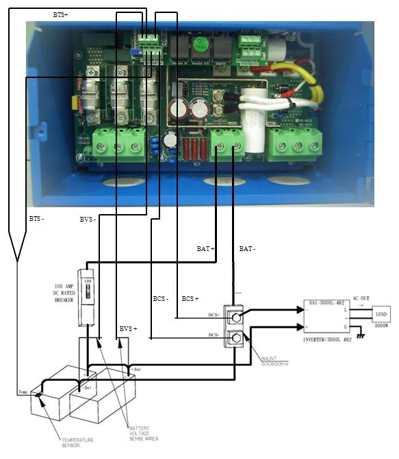
12 1.5 Shunt (BCS) The Shunt is an optional component and it is required for the WindStar MPPT to achieve to the optimal operation levels and it functions as a hub for connecting measurement sensors. The main purpose of the shunt is to allow the WindStar MPPT to measure current drawing into and out of the battery. DC load center is where the WindStar MPPT Shunt is recommend to be placed at. Or installing it in an electrical enclosure is also acceptable. Locating the Shunt is essential for safety. Please note that the capacity of the Shunt is 50mV, 500Amp. See page 1-3 for wiring connection terminal. 1.6 Battery Temperature Sensor (BTS-3) The battery temperature sensor BTS-3 is used to compensate charging by adjusting charging voltage up or down according to the temperature detected by the sensor, see page 1-3 for wiring connection terminal. The WindStar MPPT requires BTS-3 to be connected for all charging features to be available. WindStar MPPT is able to operate without the sensor but Absorption Trigger set points will be lower and equalization stage will be disabled. BTS-3 can be mounted on the battery posts. 1.7 Battery Voltage Sensing (BVS) Connecting the red wire to a battery positive bus and the black wire to a battery negative bus within the DC load center, see page 1-3 for wiring connection terminal. Two sense wires may be connected to compensate possible battery cable loss during charging. Be sure to observe correct polarity when installing voltage sense wires or damage will result. 1.8 Wiring Diagram Before starting to initiate the WindStar MPPT, keep all breakers in the OFF position. When you are ready to start the WindStar MPPT, turn on ONLY the Battery breaker. Do NOT turn on the Wind Turbine breaker until the instruction on LCD shows during WindStar MPPT initialization. The internal electric circuit of the WindStar MPPT can only be powered by the batteries. The installation environment of WindStar MPPT should be in an area of good ventilation. Never locate the WindStar MPPT in a poorly ventilated battery area because batteries emit the explosive gases. Do not locate the WindStar MPPT within 1 meter of the batteries to ensure the safety condition. See next page for the wiring diagram of WS-80CX Wind MPPT Charger as an example. 1-2
13 1-3
14 Fig-4 1-4
15 1.9 Installation Steps Example: WS-80CX Wind MPPT Charger Before starting the WS-80CX MPPT, keep the breakers, controllers in OFF position. 1. Locate the battery and WindStar MPPT Series and make sure the safety distance is at least 1 meter long. 2. Install a 100 Amp rated DC breaker and connect it to the Battery Install a Shunt of rated 500A/50mV and connect it to the Battery. 4. Connect the BAT+ terminal of the WindStar MPPT to the DC breaker. 5. Connect the BAT- terminal (next to BAT+) of the WindStar MPPT to the Shunt. 6. Install the AC breaker and connect it to the WIND TURBINE and also to the WIND INPUT terminal of the WS-80CX MPPT. 7. Connect the WIND TURBINE directly to the PE terminal (next to DL-) of the WS-80CX MPPT. 8. Connect the PE terminal of the WS-80CX MPPT to the system ground. 9. Connect the DL+ terminal of the WS-80CX MPPT to the Diversion Load Positive and connect the DL- terminal of the WS-80CX MPPT to the Diversion Load Negative. 10. To measure the current drawing into and out of the battery, connect the BCS+ terminal of WS-80CX MPPT to the Shunt + and connect the BCS- terminal of WS-80CX MPPT to the Shunt. 11. To compensate the battery charging due to the temperature difference, connect the BTS+ terminal of WS-80CX MPPT to BTS-3 Battery Temperature Sensor +and connect the BTS- terminal of WS-80CX MPPT to BTS-3 Battery Temperature Sensor. BTS-3 should be located in the battery posts. 12. To compensate the possible battery cable loss, connect the BVS+ terminal of the WS-80CX MPPT to Battery +, connect the BVS- terminal of the WS-80CX MPPT to Battery. 13. Finally, connect the DC load+ to the Battery+ and DC load to Battery through the Shunt. 1-5
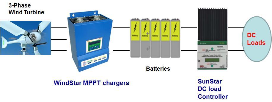
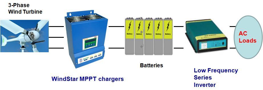
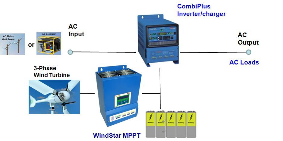
16 1.10 Applications Example: Off-grid systems Example: Hybrid system 1-6


17 Chapter 2 Wiring 2.1 Front Panel Display LCD Meter LED Indicator PB 4 PB 3 PB 2 PB 1 PB 8 PB 7 PB 6 PB 5 8 Push Buttons Push buttons Name Description PB1 PB2 PB3 Data write-in key UP key to increment setting values. UP key to go to the next selection or constant. DOWN key to decrement setting values. DOWN key to go to the last selection or constant. 2-1
18 PB4 PB5 Reset key to reset the fault. ESC key to return to the last selection level. Quick function key to the Main Menu: Data Log PB6 Quick function key to the Main Menu: Programming PB7 Quick function key to the Main Menu: Initialize PB8 Quick function key to the Main Menu: Operation 4 LED Indicators Flashing/ LEDs Solid Description Read the LCD meter for fault condition displayed. 4 fault conditions could be displayed as follows: ERROR!!! ERROR!!! FAULT Solid Red High Input Voltage WindStar Over-Temp. ERROR!!! ERROR!!! Parallel COM Failed Battery Over-Temp. EQUAL CHARGE READY Flashing Orange Flashing Green Solid Green WindStar MPPT unit is in equalization mode. Refer to constant B-09~B-12 for the setting details. WindStar MPPT unit is in charge mode. This indicates that it is functioning properly. When the voltage from the Wind Turbine is first received, the WindStar MPPT is in standby mode to charge. LCD Meter 1 LCD Meter of 20 x 2 characters is built in each WindStar MPPT unit. 2-2

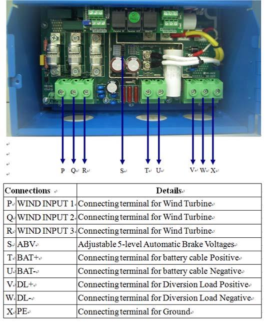
19 2.2 Control Terminal Connection A B C D E F G H I J K L M N O P Q R S T U V W X Fig-5 2-3
20 Connections Details A BVS- Connecting terminal to Battery Voltage feedback Negative B BTS- Connecting terminal for Battery Temperature Sensor Negative C BCS- Connecting terminal for optional Shunt Negative D BVS+ Connecting terminal to Battery Voltage feedback Positive E BTS+ Connecting terminal for Battery Temperature Sensor Positive F BCS+ Connecting terminal for optional Shunt Positive G Parallel IN Connections for parallel input from last WindStar MPPT H Parallel OUT Connections for parallel output I Remote Connecting terminal to Remote Panel Display J MA1 Connecting terminal for the contact A of auxiliary 1 K MC1 Connecting terminal for the common contact of auxiliary 1 L MB1 Connecting terminal for the contact B of auxiliary 1 M MA2 Connecting terminal for the contact A of auxiliary 2 N MC2 Connecting terminal for the common contact of auxiliary 2 O MB2 Connecting terminal for the contact B of auxiliary 2 P WIND INPUT 1 Connecting terminal for Wind Turbine Q WIND INPUT 2 Connecting terminal for Wind Turbine R WIND INPUT 3 Connecting terminal for Wind Turbine S ABV Adjustable 5-level Automatic Brake Voltages T BAT+ Connecting terminal for battery cable Positive U BAT- Connecting terminal for battery cable Negative V DL+ Connecting terminal for Diversion Load Positive W DL- Connecting terminal for Diversion Load Negative X PE Connecting terminal for Ground 2-4
21 2.3 Parallel Connection The parallel connection of WindStar MPPT series can be up to 16 units (1 Master and 15 Slaves) and in the parallel system, there is only one Shunt which needs to be connected to the Master unit to measure the total accumulated current. F-01=Master F-01=Slave F-02=2 F-01=Slave F-02=3 Fig-6 2-5

22 Chapter 3 User Constants 3.1 The following is the structure of user constants. 3-1
23 3. 2 The following is the Initialization Stage Flow Chart. 3-2


24 SAVE: If SAVE is selected by pressing key, the controller will save the entered settings and operate with them RCLL (RECALL): Pressing key will return to the last setting prior to entering setup. DFLT (DEFAULT): If DFLT is selected by pressing key, the controller will revert to and operate at default settings based on the original voltage, battery type and capacity entered in the initialization process. 3-3


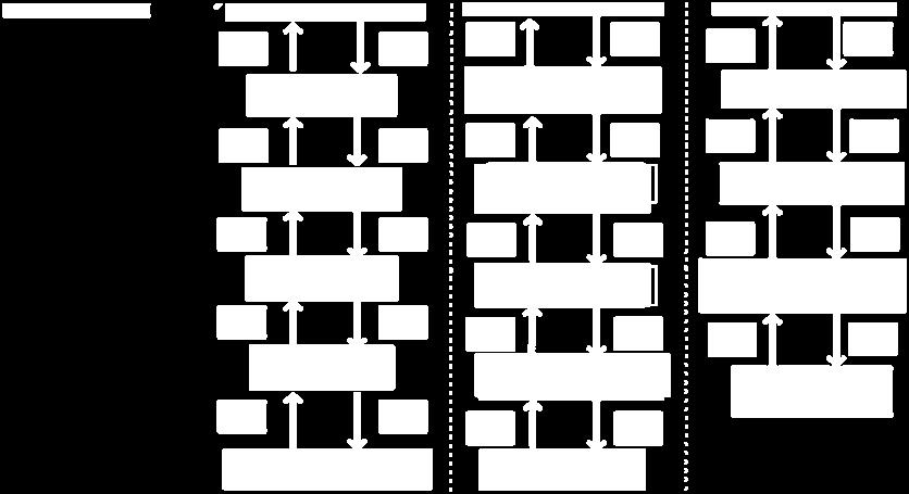
25 3.3 The following is the Operation Stage Flow Chart. Main Menu Main Menu-Operation Menu Constants 3-4
26 Main Menu-Initialize Menu Constants Constants Edit Data Enter Main Menu-Programming Group B Menu Group Constants Constants Edit Data Enter 3-5
27 Main Menu-Programming Group C Menu Group Constants Constants Edit Data Enter Main Menu-Programming Group D, D-01= ON or OFF Menu Group Constants Constants Edit Data Enter 3-6
28 Main Menu-Programming Group D, Auxiliary 1 ON/OFF Condition Setting Menu Group Constants Constants Edit Data Enter *** Main Menu *** Operation *** Main Menu *** Initialize *** Main Menu *** Programming DATA ENTER ESC RESET Group B Battery Setup Group C MPPT Setup Group D Auxiliary Relay 1 Group E Auxiliary Relay 2 Group F Network Setup Group O Operator DATA ENTER ESC RESET Set Aux Relay 1 Mode D-01=OFF Aux RY1 ON Condition D-02= <000.0 Volts Aux RY1 OFF Condition D-03= <000.0 Volts DATA ENTER ESC RESET DATA ENTER ESC RESET DATA ENTER ESC RESET Set Aux Relay 1 Mode D-01= OFF Set Aux Relay 1 Mode D-01= Solar Voltage Aux RY1 ON Condition D-02= < Volts Aux RY1 ON Condition D-02=< Volts Aux RY1 OFF Condition D-03= > Volts Aux RY1 ON Condition D-03=> Volts DATA ENTER DATA ENTER DATA ENTER DATA ENTER Entry Accepted Entry Accepted Entry Accepted Entry Accepted Aux RY1 MIN. ON time D-04= 00:00 Main Menu-Programming Group E, E-01= ON or OFF Menu Group Constants Constants Edit Data Enter *** Main Menu *** Operation *** Main Menu *** Initialize *** Main Menu *** Programming DATA ENTER ESC RESET Group B Battery Setup Group C MPPT Setup Group D Auxiliary Relay 1 Group E Auxiliary Relay 2 Group F Network Setup Group O Operator DATA ENTER ESC RESET Set Aux Relay 2 Mode E-01=OFF 3-7 DATA ENTER ESC RESET Set Aux Relay 2 Mode E-01= OFF Set Aux Relay 2 Mode E-01= ON DATA ENTER DATA ENTER Entry Accepted Entry Accepted
29 Main Menu-Programming Group E, Auxiliary 2 ON/OFF Condition Setting Menu Group Constants Constants Edit Data Enter 3-8
30 Main Menu-Programming Group F Menu Group Constants Constants Edit Data Enter 3-9
31 Main Menu-Programming Group O Menu Group Constants Constants Edit Data Enter 3-10
32 Main Menu-Data Log Menu Constants Constants Edit Data Enter 3-11
33 Chapter 4 Constant List Main Menu Group Constant LCD Display Range Unit Factory Setting Remark Page U-00 IN =xxx.xv xxx.xamps 0.1V OUT =xxx.xv xxx.xamps 0.1A 5-1 U-01 Input Voltage 0.1V 5-1 U-02 Input Current 0.1A 5-1 U-03 Output Voltage 0.1V 5-1 U-04 Output Current 0.1A 5-1 U-05 EnergyHarvestToday 1 1kWHr 1AHr 5-1 U-07 EnergyHarvestToday 2 Hr:Min 5-2 Operation U U-08 Stage of Charger 5-2 U-09 WindStar Date MM/DD/YY 5-2 U-10 WindStar Time Hr: Min: Sec 5-2 U-11 WindStar Temperature U-12 Battery SOC 1~100% 1% NOTE U-13 Battery Current 0.1A NOTE U-14 Battery Amp Hours 1AHr NOTE U-15 Battery Temperature 1 NOTE U-16 Parallel COMM Status NOTE U-17 Serial Number 5-3 Constant Set Constant A-01 Access Level Operation 5-4 Set Only Preset Initialize A No A-02 Init Parameters Setting Initialize No Initialize 5-4 A-03 Password 1 0~ NOTE A-04 Password 2 0~ NOTE Battery Setup B-01 Set Battery Voltage 12/24/36/ Programming B GEL, B-02 Set Battery Type FLOODED AGM GEL 5-5 B-04 Set Battery Capacity 0~ Ahr NOTE
34 Main Menu Group Constant LCD Display Range Unit Factory Setting Remark Page B-05 BAT. MAX Charge Amps 0~120 1A NOTE FLOOD- 13.9~ V Set Absorption ED B-06 Volts AGM 13.7~ V GEL 13.6~ V B-07 Set Absorption Time 0~ 99 Hr 59 Min 1 Min 2 Hr 5-7 B B-08 Set Float Voltage FLOOD- ED 12.9~ V AGM 12.8~ V GEL 12.8~ V Programming C 12V:14.7~ V:15.6 B-09 Set Equalize Voltage 24V:29.4~ V: V 36V:44.1~ V:46.8 NOTE V:58.8~ V:62.4 B-10 Set MAX EQU. Time 0~ 99 Hr 59 Min 1 Min 2 Hr NOTE B-11 Set Days Between EQU 0~999 1 Day OFF NOTE B-12 Manual Equalize YES/NO NO NOTE MPPT Setup P and O C-01 Set MPPT Type Scan and Hold Percentage P and O 5-8 Hold Input V C-02 Set Scan Frequency 1~4Hr 1 Min 1 Hr NOTE C-03 Set Percentage VOC 0~100 1% 80 NOTE C-04 Percentage EveryTime 1~4Hr 1 Min 1 Hr NOTE C-05 Set Hold Input Volts 0~ V NOTE 4 NOTE
35 Main Menu Group Constant LCD Display Range Unit Factory Setting Remark Page Auxiliary Relay 1 OFF, ON, Wind Voltage, Output Volts, Battery Volts, OUT Current, D-01 Set Aux Relay 1 Mode BATT Current, OFF 5-9 WindStar Temp. Battery Temp. WindStar Time Battery SOC, Output Volts Aux RY1 ON Condition See Below See See Below Below 5-10 When D-01= Wind Voltage 0~ V When D-01=Output Volts 0~64 0.1V Programming D D-02 When D-01=Battery Volts 0~64 0.1V When D-01=OUT Current 0~120 1A When D-01=BATT Current -500~500 1A When D-01=WindStar Temp. -20~ When D-01=Battery Temp. -20~ When D-01=WindStar Time 00~23 Hr 00~59 Min 1 Min When D-01=Battery SOC 0~100 1% AuxRY1 OFF Condition See Below See Below See Below 5-11 When D-01= Wind Voltage 0~ V When D-01=Output Volts 0~64 0.1V D-03 When D-01=Battery Volts 0~64 0.1V When D-01=OUT Current 0~120 1A When D-01=BATT Current -500~500 1A When D-01=WindStar Temp. -20~ When D-01=Battery Temp. -20~
36 Factory Main Menu Group Constant LCD Display Range Unit Remark Page Setting 00~23 Hr When D-01=WindStar Time 1 Min D-03 00~59 Min D When D-01=Battery SOC 0~100 1% Programming E D-04 Aux RY1 MIN. ON time 0~23 Hr, 0~59Min 1 Min Auxiliary Relay 2 OFF, ON, Wind Voltage, Output Volts, Battery Volts, OUT Current, E-01 Set Aux Relay 2 Mode BATT Current, OFF 5-12 WindStar Temp. Battery Temp. WindStar Time, Battery SOC, Output Volts Aux RY2 ON Condition See Below See See Below Below 5-12 When E-01= Wind Voltage 0~ V When E-01=Output Volts 0~64 0.1V When E-01=Battery Volts 0~64 0.1V When E-01=OUT Current 0~120 1A E-02 When E-01=BATT Current -500~500 1A When E-01=WindStar Temp. -20~ When E-01=Battery Temp. -20~ E-03 When E-01=WindStar Time 00~23 Hr 00~59 Min 1 Min When E-01=Battery SOC 0~100 1% AuxRY2 OFF Condition See Below See See Below Below 5-12 When E-01= Wind Voltage 0~ V When E-01=Output Volts 0~64 0.1V When E-01=Battery Volts 0~64 0.1V
37 Main Menu Group Constant LCD Display Range Unit Factory Setting Remark Page When E-01=OUT Current 0~120 1A When E-01=BATT Current -500~500 1A Programming Data Log E F O G When E-01=WindStar Temp. -20~ E-03 When E-01=Battery Temp. -20~ When E-01=WindStar Time 00~23 Hr 00~59 Min 1 Min When E-01=Battery SOC 0~100 1% E-04 Aux RY2 MIN. ON time 00~23 Hr 00~59 Min 1 Min Parallel Setup F-01 WindStarParallel MODE Standalone, Stand- Master, Slave alone 5-12 F-02 WindStarParallel Addr 2~16 2 NOTE Operator O-01 Set CLOCK Mode 12/24 Hr O-02 Set WindStar Time Hr: Min: Sec 5-13 O-03 Set WindStar Date MM/DD/YY 5-13 O-04 Model Number SS-xx C MPPT NOTE O-05 Turn OFF Backlight T 0~10 1 Min O-06 FAN Test ON/OFF OFF 5-14 O-07 Software Version 9.31I 5-14 O-08 ***Bootloader*** 5-14 G-01 EnergyHarvestToday 1 kwhr AHr 5-14 G-02 EnergyHarvestToday 2 Hr:Min 5-14 G-03 Set Day LOG # (1-90) 1~90 1 Day 5-14 G-04 Day LOG # : kwhr kwhr AHr 5-15 G-05 Day LOG FLOAT Hr:Min 5-15 G-07 Average Last Days kwhr xxxxx kwhr xxxx AHr AHr 5-15 G-08 Average Last Days FLOAT xx : xx Hr:Min
38 Data Log G G-09 Clear Energy Harvest Today s Data Logged Data Today s Data 5-16 NOTE 1 (U-12, U-13, U-14, U-15) Battery SOC, Battery Current and Battery Amp Hours will only be visible when terminal BVS (Battery Voltage Sensing) is connected to the battery and will only be active when using an optional 50mv/500amp external shunt. Battery Temperature will only be visible when terminal BVS (Battery Voltage Sensing) is connected to the battery and will only be active when using a Battery Temperature Sensor (BTS-3). These four constants will only be displayed when the terminal BVS (Battery Voltage Sensing) is wired to the battery. To show the precise values, an optional 50mv/500amp external shunt is needed for U-12, U-13, U-14 and a Battery Temperature Sensor is needed for U-15. NOTE 2 (A-03, A-04) These two constants are reserved for the authorized distributor or technician to lock the constants operation. Lock the constants setting 1. Finish setting all the programmable constants to the desired values. 2. Change A-01=Operation Only, factory setting is A-01=Constants Set. 3. Use UP key to go to A-03 to enter the password 1 (max. 4 digits) 4. Go to any display of A-xx and press DOWN key and hold it, then press ESC key at the same time till A-04 constant occurs. 5. Enter the desired password 2 (max. 4 digits) into A-04. Make sure the password 1 in A-03 must be different from the password 2 in A-04. Finally, press ENTER key to finish lock setting. Above procedure completes locking the constants setting and no more programming selection would appear. A-01 would only display Operation only and would not display Constants Set. Unlock the constants setting 1. Enter the password in A-03 to be exactly the same as the one earlier set in A When the password in A-03 matches the one earlier set in A-04, the unlocking is completed. A-01=Constants Set would appear again for programming. 4-6
39 NOTE 3 (B-09, B-10, B-11, B-12) These constants are only displayed if Flooded is selected as battery type (B-02). NOTE 4 (C-02, C-03, C-04, C-05) C-02 is only displayed if P and O or Scan and Hold is selected as MPPT Type (C-01). C-03 and C-04 are only displayed if Percentage is selected as MPPT Type (C-01). C-05 is only displayed if Hold Input V is selected as MPPT Type (C-01). NOTE 5 (U-16, F-02) U-16 and F-02 are only displayed if Slave is selected as WindStar Network MODE (F-01). NOTE 6 (B-04, B-05, C-05, O-04) The factory settings of the listed constants are dependent on the different model numbers. Constant LCD Display WS-120CX MPPT WS-80CX MPPT Factory Setting Factory Setting B-04 Set Battery Capacity 2400 Ahr 1600Ahr B-05 Bat. MAX Charge Amps 120A 80A C-05 Set Hold Input Volts 240Vdc 240Vdc O-04 Model Number WS-120CX MPPT WS-80CX MPPT Constant LCD Display WS-50CX MPPT Factory Setting B-04 Set Battery Capacity 1000 Ahr B-05 Bat. MAX Charge Amps 50A C-05 Set Hold Input Volts 240Vdc O-04 Model Number WS-50CX MPPT 4-7
40 Chapter 5 Programming Constants *** Main Menu*** Operation U-00: IN=xxx.xV xxx.xamps OUT=xxx.xV xxx.xamps Use Constant U-00 to monitor the power coming in from the Wind Turbine in Volts and Amps. The second line displays the power going out of the WINDSTAR MPPT, it also displays in Volts and Amps. In most installations there will be a difference between incoming volts and outgoing volts. This reflects the flexibility of the WINDSTAR MPPT with respect to Wind Turbine input voltage vs. battery voltage. Incoming and outgoing amps will also differ because they are the result of dividing watts (a constant) by volts. U-01: Input Voltage This screen displays the input voltage value coming from the Wind Turbine in Volts. U-02: Input Current This screen displays the input current value coming from the Wind Turbine in Amps. U-03:Output Voltage This screen displays the power going out of the WINDSTAR MPPT in Volts. U-04: Output Current This screen displays the power going out of the WINDSTAR MPPT in Amps. 5-1
41 U-05: EnergyHarvest Today 1 This screen displays how much the wind energy was harvested Today in kwhr and AHr. U-07: EnergyHarvest Today 2 This screen displays how much time the charger was in Float mode Today in Hour:Minute. U-08: Stage of Charger This screen displays the charging stage of WINDSTAR MPPT. The possible values are Charger Off, Charger Start, BULK Stage, ABSORP Stage, FLOAT Stage, Charger MPPT, Charger Stop, EQUALZ Stage. U-09: WindStar Date This screen displays the date according to the setting of initialization stage. The display format is MM/DD/YY. U-10: WindStar Time This screen displays the time according to the setting of initialization stage. U-11: WindStar Temperature This screen displays the temperature detected in WINDSTAR MPPT Battery Charger. U-12: Battery SOC This screen displays the stage of charge (SOC) as a percentage of fully charged. SOC will only be visible when terminal BVS (Battery Voltage Sensing) is connected to the battery and will only be active when using an optional 50mv/500amp external shunt. U-12 will only be displayed when the terminal BVS (Battery Voltage Sensing) is wired to the battery. To show the precise values, an optional 50mv/500amp external shunt is needed. 5-2
42 U-13: Battery Current This screen displays the battery current in Amps. Battery Current will only be visible when terminal BVS (Battery Voltage Sensing) is connected to the battery and will only be active when using an optional 50mv/500amp external shunt. U-13 will only be displayed when the terminal BVS (Battery Voltage Sensing) is wired to the battery. To show the precise values, an optional 50mv/500amp external shunt is needed. U-14: Battery Amp Hours This screen displays the battery capacity in AHr (Amp Hours). Battery Amp Hours will only be visible when terminal BVS (Battery Voltage Sensing) is connected to the battery and will only be active when using an optional 50mv/500amp external shunt. U-14 will only be displayed when the terminal BVS (Battery Voltage Sensing) is wired to the battery. To show the precise values, an optional 50mv/500amp external shunt is needed. U-15: Battery Temperature This screen displays the battery temperature in. Battery Temperature will only be visible when Battery Voltage Sensor is connected and will only be active when using a Battery Temperature Sensor (BTS-3). U-15 will only be displayed when the terminal BVS (Battery Voltage Sensing) is wired to the battery. To show the precise values, a Battery Temperature Sensor (BTS-3) is needed to be wired to terminal BTS. U-16: Parallel COMM Status This screen displays the communication status between Master unit and Slave units. U-16 is only displayed when Slave is selected as WINDSTAR Network MODE (F-01). When the communication is successful, the screen displays SLAVE UNIT. When the communication fails, then screen displays NETWORK ERROR. 5-3
43 U-17: Serial Number This screen displays the unit serial number. It is useful when contacting Rich Electric Technical Support. *** Main Menu*** Initialize A-01: Access Level Use Constant A-01 to select the user constant access level. This level determines which user constants can be changed and displayed. Settings: A-01=Constant Set (Factory Setting) This setting allows all user constants to be changed and displayed. A-01=Operation Only This setting allows the Operation and Initialize to be changed or displayed. A-02: Init Parameters Use Constant A-02 to initialize the user constants. When initialized, the user constants will return to their factory preset values. You should normally record the setting of any constants that are changed from factory presets. Settings: A-02=Preset Setting This setting allows to initialize the user constants to factory settings. A-02=No Initialize (Factory Setting) This setting does not initialize any user constants. A-03: Password 1 A-04: Password 2 These two constants are reserved for the factory to test and set the functions. 5-4
44 Users are not allowed to set these two constants. Lock the constants setting 1. Finish setting all the programmable constants to the desired values. 2. Change A-01=Operation Only, factory setting is A-01=Constants Set. 3. Use UP key to go to A-03 to enter the password 1 (max. 4 digits) 4. Go to any display of A-xx and press DOWN key and hold it, then press ESC key at the same time till A-04 constant occurs. 5. Enter the desired password 2 (max. 4 digits) into A-04. Make sure the password 1 in A-03 must be different from the password 2 in A-04. Finally, press ENTER key to finish lock setting. Above procedure completes locking the constants setting and no more programming selection would appear. A-01 would only display Operation only and would not display Constants Set. Unlock the constants setting 1. Enter the password in A-03 to be exactly the same as the one earlier set in A When the password in A-03 matches the one earlier set in A-04, the unlocking is completed. A-01=Constants Set would appear again for programming. *** Main Menu*** Programming Group B Battery Setup B-01: Set Battery Voltage During initialization of WINDSTAR MPPT, it will detect and ask the installer to confirm the battery voltage found is correct. In almost all circumstance the WINDSTAR MPPT will correctly detect battery voltage. Use Constant B-01 to change the battery voltage if the battery voltage displayed by the WINDSTAR MPPT is different from the installed batteries. The selection range of the battery voltage is 12V (Factory Setting), 24V, 36V and 48V. B-02: Set Battery Type Use UP or DOWN keys to allow the installer to change what type of batteries it 5-5
45 is connected to (Flooded, Gel, AGM) SUNSTAR MPPT. The default BATTERY TYPE is GEL Please be sure to select the type which matches the system s batteries. This setting controls battery charging voltages in B-06 and B-08. B-04: Set Battery Capacity This setting controls battery charging amperages and other settings. The factory setting for CAPACITY is 2400 amp hours for WS-120CX MPPT, 1600 amp hours for WS-80CX MPPT and 1000 amp hours for WS-50CX MPPT. At full output capacity a WS-80CX MPPT can deliver 80 amps to a battery, this amount of amperage (current) is equal to the C/10 (capacity divided by ten) rate of a 1600 amp hour battery and, as such meets most manufacturers recommendations for minimum Wind charging capacity. In applications with battery banks under 1600 amp hours it is recommended to lower the Maximum Charge Rate setting from the default 80 amps to the C10 rate of the battery bank. B-05: BAT. MAX Charge Amps Use Constant B-05 to allow the installer to limit the maximum charge amps allowed to the batteries. The factory setting is 120 amps (WS-120CX MPPT), 80 amps (WS-80CX MPPT) and 50 amps (WS-50CX MPPT). B-06: Set Absorption Volts Use Constant B-06 to adjust the Absorption voltages. The default values are based on the battery type and capacity selected. It is not advisable to change default settings unless advised by the battery manufacturer or supplier. Battery Type Absorption Volts Factory Range Setting FLOODED 13.9V~15.2V 14.6V AGM 13.7V~15.1V 14.1V GEL 13.6V~15.1V 14.1V The above values are based on 12V system. The values x 2 are for 24V 5-6
46 system; the values x 3 are for 36V system and the values x 4 are for 48V system. WINDSTAR MPPT series will charge at the Absorption voltage and at the length of time before switching to float mode. B-07: Set Absorption Time Use Constant B-07 to adjust the length of Absorption time. The factory setting is 2 hours (displayed as 02:00). B-08: Set Float Voltage Use Constant B-08 to adjust the Float voltages. The default set values are based on the battery type and capacity selected. It is not advisable to change default settings unless advised by the battery manufacturer or supplier. Battery Type Float Volts Range Factory Setting FLOODED 12.9V~14.2V 13.8V AGM 12.8V~14.2V 13.2V GEL 12.8V~14.1V 13.5V The above values are based on 12V system. The values x 2 are for 24V system; the values x 3 are for 36V system and the values x 4 are for 48V system. B-09: Set Equalize Voltage This constant is only displayed if Flooded is selected as battery type (B-02). Use Constant B-09 to select the Equalize voltages. The default values are based on the battery voltage and capacity selected. It is not recommended to change default settings unless advised so by the battery manufacturer or supplier. Battery Type FLOODED Battery Factory Equalization Volts Range Voltage Setting 12V 14.7V~16.4V 15.6V 24V 29.4V~32.8 V 31.2V 36V 44.1V~49.2V 46.8V 48V 58.8V~65.6V 62.4V 5-7
47 B-10: Set MAX EQU. Time This constant is only displayed if Flooded is selected as battery type (B-02). Use Constant B-10 to select the time of equalization time. The factory setting is 2 hours (displayed as 02:00). B-11: Set Days Between EQU This constant is only displayed if Flooded is selected as battery type (B-02). Use Constant B-11 to select the number of days between equalization charges. The factory setting is OFF. B-12: Manual Equalize This constant is only displayed if Flooded is selected as battery type (B-02). Use Constant B-12 to choose between manual and automatic equalization settings. Press ENTER key to select Yes for manual equalization and then it will display the Equalize voltage set in B-09 and the Max. EQU time set in B-10. Press ENTER key again to start the manual equalization. During equalization, only ESC key is active to leave the equalization process screen. After the manual equalization starts, BAT displays Battery voltage. Battery temperature and Equalizing blinks in return. CHARGE displays charging current. Finally, the remaining time for equalization charge is counted down. WARNING: Before the manual equalization is selected, WINDSTAR MPPT should be connected to Battery Temperature Sensor (BTS-3). If it is not connected to BTS-3, Warning, Bat. Sr Not Connected is displayed. Press ESC key to select No to return to the display of Group B. Group C MPPT Setup C-01: Set MPPT Type 5-8
48 Use Constant C-01 to set up the MPPT type: P and O, Scan and Hold, Percentage, Hold Input V. The factory setting is P and O. C-02: Set Scan Frequency This constant is only displayed if P and O or Scan and Hold is selected as MPPT Type (C-01). The scan frequency is settable from 1 minute to 4 hours and the factory setting is 1 hour. Press the UP and DOWN key to increase or decrease the length of time. P and O (Perturb and Observe) will run a full scan at the set time interval (frequency) and then do P and O scans at shorter intervals in between. Scan and Hold will run a full scan at the set time interval (frequency) and then hold the resultant MP until the next interval. This is also settable from 1 minute to 4 hours; factory is 1 hour. C-03: Set Percentage VOC This constant is only displayed if Percentage is selected as MPPT Type (C-01). Percentage measures the VOC at the set time interval and calculates the operating Vmp based on the percentage set. The percentage set point can be from 0 100% and factory setting is 80%. C-04: Set Percentage EveryTime This constant is only displayed if Percentage is selected as MPPT Type (C-01). When Percentage measure the VOC, the time interval can be set and time is 1 minute to 4 hours. Factory setting is 1 hour. C-05: Set Hold Input Volts This constant is only displayed if Hold Input V is selected as MPPT Type (C-01). Hold Input Voltage will regulate based on the input voltage set (0-240V) for WS-120CX MPPT, WS-80CX MPPT and WS-50CX MPPT, based on the Wind Turbine type. The output current will be based on that voltage. Group D Auxiliary Relay 1 5-9
49 D-01: Set Aux Relay 1 Mode The Auxiliary Relays are useful for functions such as turning a generator on or off at low battery voltage or load change, turning on an external fan when battery temperature increases, or shedding certain loads at specific times. Additional functions will be added in the future. Use Constant D-01 to select the Auxiliary Relay 1 mode and what it is based on. Auxiliary Relay 1 Mode includes OFF, ON, Wind Voltage, Output Voltage, Battery Voltage (only displayed and active when terminal BVS is connected to the battery), Output Current, Battery Current (only active when terminal BCS is connected with a Shunt 50mV, 500Amp), WindStar Temperature, Battery Temperature (only active when terminal BTS is connected with a Battery Temperature Sensor, BTS-3), WindStar Time and Battery State of Charge(only displayed when terminal BCS is connected with Shunt 500Amp, 50mV). The factory setting is OFF. D-02, D-03 and D-04 will not be displayed, when D-01 is set to be ON or OFF. D-02: Aux RY1 ON Condition According to 9 selectable modes in D-01, use Constant D-02 to set the condition to activate the Auxiliary Relay 1 to be ON. The displayed setting range of D-02 will change to less than or greater than (< or >) depending on if D-02 or D-03 is higher or lower value. This allows setting on either a rising or falling voltage. Once entering the D-02, use UP and DOWN keys to increment and decrement the values. Aux RY1 ON Condition Setting Range of D-02 Setting Unit When D-01= Wind Voltage < or > 0~240V 0.1V When D-01=Output Volts < or > 0~64V 0.1V When D-01=Battery Volts < or > 0~64V 0.1V Battery Voltage is only displayed and active when terminal BVS is connected to the battery. When D-01=OUT Current < or > 0~120A 1A When D-01=BATT Current < or > -500~500A 1A Battery Current is only active when terminal BCS is connected with a Shunt 50mV, 500Amp. The values may be positive or negative as this input reads load current as 5-10
50 well as charge current. When D-01=WindStar Temp. < or > -20~100 1 When D-01=Battery Temp. < or > -20~100 1 Battery Temperature is only active when terminal BTS is connected with a Battery Temperature Sensor (BTS-3). When D-01=WindStar Time < or > 00~23 Hr 00~59 Min 1 Min When D-01=Battery SOC < or > 0~100% 1% Battery SOC is only active when terminal BCS is connected with a Shunt 50mV, 500Amp. D-03: Aux RY1 OFF Condition According to 9 selectable modes in D-01, use Constant D-03 to set the condition to activate the Auxiliary Relay 1 to be OFF. The displayed setting range of D-03 will change to less than or greater than (< or >) depending on if D-02 or D-03 is higher or lower value. This allows setting on either a rising or falling voltage. Once entering the D-03, use UP and DOWN keys to increment and decrement the values. Aux RY1 OFF Condition Setting Range of D-03 Setting Unit When D-01= Wind Voltage < or > 0~240V 0.1V When D-01=Output Volts < or > 0~64V 0.1V When D-01=Battery Volts < or > 0~64V 0.1V Battery Voltage is only displayed and active when terminal BVS is connected to the battery. When D-01=OUT Current < or > 0~120A 1A When D-01=BATT Current < or > -500~500A 1A Battery Current is only active when terminal BCS is connected with a Shunt 50mV, 500Amp. The values may be positive or negative as this input reads load current as well as charge current. When D-01=WindStar Temp. < or > -20~100 1 When D-01=Battery Temp. < or > -20~100 1 Battery Temperature is only active when terminal BTS is connected with a Battery Temperature Sensor (BTS-3). 5-11
51 When D-01=WindStar Time < or > 00~23 Hr 00~59 Min 1 Min When D-01=Battery SOC < or > 0~100% 1% Battery SOC is only active when terminal BCS is connected with a Shunt 50mV, 500Amp. D-04: Aux RY1 MIN. ON time Use Constant D-04 is to set the minimum time that the relay can remain active. The minimum time is set to avoid the difference of the values set in D-02 and D-03 is so small to cause the damage on the relay due to the high frequency of relay action between ON and OFF. Group E Auxiliary Relay 2 E-01: Set Aux Relay 2 Mode E-02: Aux RY2 ON Condition E-03: Aux RY2 OFF Condition E-04: Aux RY2 MIN. ON time The functions and the settings of Auxiliary Relay 2 are exactly the same as those of Auxiliary Relay 1 so please refer to above Group D, Auxiliary Relay 1 description. Group F Parallel Setup F-01: WindStarParallel MODE Use Constant F-01 to set up WINDSTAR MPPT Network. Each WINDSTAR MPPT in parallel requires a mode and address entry. The Mode choices are: Setting Usage Used when there is only one WINDSTAR MPPT with a Standalone Remote Display connected. Used to assign the network master (this is the WINDSTAR Master MPPT that connects to the shunt). 5-12
52 Slave Assigns up to 15 additional WINDSTAR MPPT slave units. The first WINDSTAR MPPT is assigned as master and the rest of units in network are slaves. The network address will be assigned to each slave unit in F-02. F-02: WindStarParallel Addr A WINDSTAR MPPT assigned as Master or Standalone is always addressed 01 automatically so the address assignment in F-02 is only available for the slave units. The maximum slave address number is 16 and the factory setting is 2. Group O Operator O-01: Set CLOCK Mode This is the same display as in the initialization setup of battery. Use Constant O-01 to change and select the hour format displayed between 12 Hour and 24 Hour. Factory setting is 12 Hour Format. When 12 Hour is selected, AM and PM indication will be shown in O-02. O-02: Set WindStar Time This is the same display as in the initialization setup of battery. When 12 Hour format is selected in O-01, AM and PM indication will be shown. Press ENTER to start to edit the Hour:Minute: Second number and press UP and DOWN key to increment or decrement the values. O-03: Set WindStar Date This is the same display as in the initialization setup of battery. Press ENTER key to start to edit the MM/DD/YY and press UP and DOWN key to increment or decrement the values. O-04: Model Number 5-13
53 The model number of the unit is displayed. O-05: Turn OFF Backlight T Use Constant O-05 to set the operation of the LCD backlight. Since the backlight consumes a fair amount of quiescent current, it is recommended that the on time be as short as possible. Press ENTER key to enter the setting and press UP and DOWN key to turn off from NEVER (always on) or 1 to 10 minutes in 1 minute increments. Note: When the backlight turns off, pressing any key will turn it back to U-00 display screen. O-06: Fan Test Use Constant O-06 to test if the fan can be forced to be ON or OFF. When FAN ON is selected, the fan test is conducted as the O-06 screen remains. Once the screen leaves O-06, it will stop the test running. O-07: Software Version The software version displayed is important and useful when contacting Rich Electric Technical Support. O-08: ***Bootloader*** This is the Bootloader initiation display. It is only used to update the firmware. *** Main Menu*** Data Log G-01: EnergyHarvest Today 1 This screen displays how much the wind energy was harvested Today in kwhr and AHr unit. G-02: EnergyHarvest Today
54 This screen displays how much time the charger was in Float mode Today. It is valuable to know that the charger enters Float mode because this is a clear indication that the batteries have been fully recharged. If the value displayed in G-02=FLOAT is consistently Hr, it means that the Wind Turbine is not sufficiently sized to keep up with the load. Use a generator for additional battery charging, reduce loads, or expand the Wind Turbine to ensure that batteries are fully recharged. For maximum service life batteries should be fully recharged at least once every five to ten days. G-03: Set Day LOG# (1-90) Use G-03 to set the Day Log number to display the energy harvested from Wind Turbine (shown in G-04 and G-05) by WINDSTAR MPPT over a period of time. If it is selected as #2 displays past power production since the last power cycle (or up to 90 days previous) along with the date of day before the current date. Use UP and DOWN keys to select the date by one and the energy harvested on the date shown is displayed in G-04. G-04: Day LOG# :kwhr This screen displays how much the wind energy was harvested in kwhr and AHr according to the selected day shown in G-03. G-05: Day This screen displays how much time the charger was in Float mode according to the selected day shown in G-03. G-07: Average Last Days xxxxx kwhr xxxx AHr This screen shows the average power produced over the past cumulative days as both in kwhr and AHr. G-08: Average Last FLOAT xx : xx Days This screen displays how much average time the charger was in Float mode in 5-15
55 the past cumulative days, shown in Hour: Minute. G-09: Clear Energy Harvest Use Constant G-09 to clear Today s Data or all the Logged Data. Press ENTER key and use UP and DOWN keys to select between Today s Data and Logged Data and then press ENTER key again to clear the selected data. 5-16
56 Chapter 6 Trouble Shooting Proceed as follows for a quick detection of common faults. Consult your Rich Electric dealer if the fault cannot be resolved. Problem or Error message Cause Solution ERROR!!! High Input Voltage When the Wind Turbine voltage is higher than 240VDC for WindStar MPPT Chargers, the battery charging stops. Make sure the Wind Turbine voltage is within the rated voltage range. Make sure the diversion load is good. ERROR!!! WindStar Over-Temp. ERROR!!! Battery Over-Temp. ERROR!!! Parallel COM Failed The ambient temperature is too high and it causes the over temperature of heatsink. The battery temperature is detected too high by the Battery Temperature Sensor (BTS-3). The communication failure between Master and Slave units or between Slave and Slave units has occurred. Place the WindStar MPPT unit in a cool and well-ventilated room. Check the battery condition and place the battery bank in an well-ventilated room. Check the connecting cables between Master and Slave units or the cables among Slaves. 6-1
OPTI-Solar SC MPPT Series
 www.opt i -sola r. c o m OPTI-Solar SC MPPT Series SOLAR CHARGE CONTROLLER SC-50 / SC-80 / SC-80X / SC-160X MPPT Installation and Operation Manual CONTENTS Introduction... Feature... Specification... Dimension...VII
Invertek. Battery Management Control System DC-SW-140 & DC-SW-140C DC-SW-70 & DC-SW-70C USER MANUAL
 利佳興業股份有限公司 RICH ELECTRIC CO.,LTD. Invertek Battery Management Control System DC-SW-140 & DC-SW-140C DC-SW-70 & DC-SW-70C USER MANUAL Rich Electric Co. DC-SW Battery Management Control System User Manual
APOLLO SOLAR. TurboCharger T80 Installation and Operation Manual. T80 Installation and Operation Manual
 APOLLO SOLAR TurboCharger T80 Installation and Operation Manual T80 Installation and Operation Manual TurboCharger T80 Installation and Operation Manual Page 1 TABLE OF CONTENTS Revision History...2 Important
User Manual Solar Charge Controller 3KW
 User Manual Solar Charge Controller 3KW Version: 1.3 CONTENTS 1 ABOUT THIS MANUAL... 1 1.1 Purpose... 1 1.2 Scope... 1 1.3 SAFETY INSTRUCTIONS... 1 2 INTRODUCTION... 2 2.1 Features... 2 2.2 Product Overview...
User Manual. Solar Charge Controller 3KW
 User Manual Solar Charge Controller 3KW 1 CONTENTS 1 ABOUT THIS MANUAL... 3 1.1 Purpose... 3 1.2 Scope... 3 1.3 SAFETY INSTRUCTIONS... 3 2 INTRODUCTION... 4 2.1 Features... 4 2.2 Product Overview... 5
Rover Series. Rover 20A 40A Maximum Power Point Tracking Solar Charge Controller
 Rover Series Rover 20A 40A Maximum Power Point Tracking Solar Charge Controller 0 2775 E. Philadelphia St., Ontario, CA 91761 1-800-330-8678 Version 1.5 Important Safety Instructions Please save these
Eclipse Solar Suitcase
 Eclipse Solar Suitcase Renogy 100W 200W 2775 E. Philadelphia St., Ontario, CA 91761 1-800-330-8678 Version 1.0 Important Safety Instructions Please save these instructions. This manual contains important
HX-VWG2008. Wind & Solar Hybrid Charge Controller. User Manual
 HX-VWG2008 Wind & Solar Hybrid Charge Controller User Manual Please read this manual very carefully. Failure to do so may result in serious injury and permanent damage to the hybrid charge controller and
βeta 20A AUTO 12V/24V SOLAR CHARGE CONTROLLER WITH REMOTE METER
 βeta 20A AUTO 12V/24V SOLAR CHARGE CONTROLLER WITH REMOTE METER USER MANUAL βeta 20A AUTO 12V/24V SOLAR CHARGE CONTROLLER WITH REMOTE METER (OPTIONAL) CHARACTERISTICS LCD display: all systems parameters
SCC-MPPT Solar Charge Controller
 Solar Charge Controller Quick Guide 200W 300W 400W 600W 850W V. 2.2 1. Introduction solar charge controller uses PWM-based DSP controller to keep the batteries regulated and prevent batteries from overcharging
Advanced Hybrid Wind / Solar Charge Controller. User Manual
 Advanced Hybrid Wind / Solar Charge Controller User Manual Safety 1. Please read the instructions carefully prior to product use or installation and refer back to them throughout the installation. 2. This
CENTAURI ENERGY SERVER TECHNICAL DATA kw POWER
 Chassis Inverter power Rated input Rated output Battery pack Safeties Environment Others Input Voltage Lower Limit Input Voltage Upper Limit Power Input Current Output Voltage Output accuracy Transient
BBC-3140 USER MANUAL DC-DC CHARGER / BATTERY EQUALIZER / VOLTAGE REDUCER
 BBC-3140 USER MANUAL DC-DC CHARGER / BATTERY EQUALIZER / VOLTAGE REDUCER Important The BBC -3140 must be used according to the local safety standards with the particular application. All wiring and connections
SCC-MPPT Solar Charge Controller
 Table 3: Charging voltage for 4 types of battery Battery Battery 12V battery system 24V battery system Type Type Code Bulk Floating Bulk Floating Vented 01 14.3 V 13.2 V 28.6 V 26.4 V Sealed 02 14.3 V
SCC-MPPT Solar Charge Controller
 Table 4: Alarm point for low battery voltage table Model Alarm point SCC-MPPT-300 10.5 V SCC-MPPT-600 21.0 V Table 5: Charging hour table for reference Battery Capacity To 90% capacity @ 25A charging current
User manual. Solar Hybrid 1-5KVA. Uninterruptible Power Supply / Charger
 User manual Solar Hybrid 1-5KVA Uninterruptible Power Supply / Charger All rights reserved. The information in this document is subject to change without notice. Thank you for purchasing this series UPS.
Installation and Operating Instructions. MPPT Solar System Controller ISC3040
 Installation and Operating Instructions MPPT Solar System Controller ISC3040 ABOUT THIS MANUAL These operating instructions come with the product and should be kept with it as a reference to all user s
Solar Charge Controller
 Table 3: Charging voltage for 4 types of battery Battery Type Battery Type Code SC-600W MPPT Bulk Voltage Floating Voltage Vented 01 28.6 V 26.4 V Sealed 02 28.6 V 26.8 V Gel 03 28.6 V 27.4 V NiCd 04 28.6
Instruction Manual. Duo-battery Solar Panel Controller EPIP20-DB series For Both 10 and 20 amp. Controllers (for use with solar panels only) + -
 + -") Instruction Manual Duo-battery Solar Panel Controller EPIP20-DB series For Both 10 and 20 amp. Controllers (for use with solar panels only) + - Optional - Switch to disconnect solar panel when engine alternator
Instruction Manual Duo-battery Solar Panel Controller EPIP20-DB series For Both 10 and 20 amp. Controllers (for use with solar panels only) + - Optional - Switch to disconnect solar panel when engine alternator
INSTALLATION INFORMATION
 INSTALLATION INFORMATION BMS ZE6000i-PCBT.xxxx / ver. 2 Programmable battery management system for Lithium Ion battery cells, for up to 32 round or prismatic cells, 10 to 400Ah NOTE: This installation
User Manual 1KVA-5KVA (PF1) INVERTER / CHARGER. Version: 1.0
 INVERTER / CHARGER. Version: 1.0") User Manual 1KVA-5KVA (PF1) INVERTER / CHARGER Version: 1.0 Table Of Contents ABOUT THIS MANUAL... 1 Purpose... 1 Scope... 1 SAFETY INSTRUCTIONS... 1 INTRODUCTION... 2 Features... 2 Basic System Architecture...
User Manual 1KVA-5KVA (PF1) INVERTER / CHARGER Version: 1.0 Table Of Contents ABOUT THIS MANUAL... 1 Purpose... 1 Scope... 1 SAFETY INSTRUCTIONS... 1 INTRODUCTION... 2 Features... 2 Basic System Architecture...
OPERATING MANUAL Digital Diesel Control Remote control panel for WhisperPower generator sets
 Art. nr. 40200261 OPERATING MANUAL Digital Diesel Control Remote control panel for WhisperPower generator sets WHISPERPOWER BV Kelvinlaan 82 9207 JB Drachten Netherlands Tel.: +31-512-571550 Fax.: +31-512-571599
SimpliPhi Power PHI Battery
 Power. On Your Terms. SimpliPhi Power PHI Battery INTEGRATION GUIDE: VICTRON Optimized Energy Storage & Management for Residential & Commercial Applications Utilizing Efficient, Safe, Non-Toxic, Energy
SimpliPhi Power PHI Battery
 Power. On Your Terms. SimpliPhi Power PHI Battery INTEGRATION GUIDE: MAGNUM ENERGY Optimized Energy Storage & Management for Residential & Commercial Applications Utilizing Efficient, Safe, Non-Toxic,
SMT. Installation and Operation Manual. Model:SMT WITH MPPT TECHNOLOGY
 SMT WITH MPPT TECHNOLOGY Installation and Operation Manual Model:SMT SMT Dimensions Specification Summary System Voltage 12 V/24V Rated Battery Current 12V, 5A 8A 10A 15A 20A 25A 24V, 5A 8A 10A 15A Rated
User Manual 1KVA-5KVA INVERTER / CHARGER
 User Manual 1KVA-5KVA INVERTER / CHARGER Version: 1.7 Table Of Contents ABOUT THIS MANUAL... 1 Purpose... 1 Scope... 1 SAFETY INSTRUCTIONS... 1 INTRODUCTION... 2 Features... 2 Basic System Architecture...
Solar Hybrid Inverter SP Brilliant Series
 User Manual Solar Hybrid Inverter SP Brilliant Series Version: 1.5 Table Of Contents ABOUT THIS MANUAL... 1 Purpose... 1 Scope... 1 SAFETY INSTRUCTIONS... 1 INTRODUCTION... 2 Features... 2 Basic System
Manual. EN Appendix. Lynx Ion BMS 400A / 1000A
 Manual EN Appendix Lynx Ion BMS 400A / 1000A 1. SAFETY INSTRUCTIONS 1.1 In general Please read the documentation supplied with this product first, so that you are familiar with the safety signs en directions
IMPORTANT. Always connect the batteries first. Use for 12V battery system only 12V (36 cells) solar panel array.
 solar panel array.") EN Appendix Manual IMPORTANT Always connect the batteries first. Use for 12V battery system only 12V (36 cells) solar panel array. Use for 24V battery system only 24V (72 cells) solar panel array. BlueSolar
EN Appendix Manual IMPORTANT Always connect the batteries first. Use for 12V battery system only 12V (36 cells) solar panel array. Use for 24V battery system only 24V (72 cells) solar panel array. BlueSolar
User Manual 1.5KVA-3KVA INVERTER / CHARGER
 User Manual 1.5KVA-3KVA INVERTER / CHARGER Version: 1.0 Table Of Contents ABOUT THIS MANUAL... 1 Purpose... 1 Scope... 1 SAFETY INSTRUCTIONS... 1 INTRODUCTION... 2 Features... 2 Basic System Architecture...
MPPT Controller PVTS Series User Manual. User Manual. 800W-4000W Hybrid solar inverter. Version: 1.4
 User Manual 800W-4000W Hybrid solar inverter Version: 1.4 Table Of Contents ABOUT THIS MANUAL... 1 Purpose... 1 Scope... 1 SAFETY INSTRUCTIONS... 1 INTRODUCTION... 2 Features... 2 Basic System Architecture...
1KVA/ 2KVA/ 3KVA/ 4KVA/ 5KVA MS, LV MPPT INVERTER / CHARGER. User Manual. Version: 2.3
 1KVA/ 2KVA/ 3KVA/ 4KVA/ 5KVA MS, LV MPPT INVERTER / CHARGER User Manual Version: 2.3 Table Of Contents ABOUT THIS MANUAL... 1 Purpose... 1 Scope... 1 SAFETY INSTRUCTIONS... 1 INTRODUCTION... 2 Features...
MPPT75HV MAXIMUM POWER POINT TRACKING SOLAR BATTERY CHARGE CONTROLLER
 MPPT75HV MAXIMUM POWER POINT TRACKING SOLAR BATTERY CHARGE CONTROLLER The Intronics Power Inc. MPPT75HV Solar Charge Controller continually tracks the maximum power point of the solar panel array, adjusting
VC-4820 Programmable DC-DC Converter with Battery Charger function USER'S MANUAL
 1. INTRODUCTION VC-4820 Programmable DC-DC Converter with Battery Charger function USER'S MANUAL This MCU controlled Step Down DC-DC Converter has a digitally adjustable output in 0.2V increments. This
The Traveler Series: Wanderer
 The Traveler Series: Wanderer RENOGY 30A Charge Controller Manual 2775 E. Philadelphia St., Ontario, CA 91761 1-800-330-8678 Version: 2.0 Important Safety Instructions Please save these instructions. This
User Manual 1.5KVA-3KVA INVERTER / CHARGER. Version: 1.1
 User Manual 1.5KVA-3KVA INVERTER / CHARGER Version: 1.1 Table Of Contents ABOUT THIS MANUAL... 1 Purpose... 1 Scope... 1 SAFETY INSTRUCTIONS... 1 INTRODUCTION... 2 Features... 2 Basic System Architecture...
User Manual 5KVA/5KW INVERTER / CHARGER. Version: 1.3
 User Manual 5KVA/5KW INVERTER / CHARGER Version: 1.3 Table Of Contents ABOUT THIS MANUAL... 1 Purpose... 1 Scope... 1 SAFETY INSTRUCTIONS... 1 INTRODUCTION... 2 Features... 2 Basic System Architecture...
BC-1230P/ 1240P/ 1260P Multi-Stage Battery Chargers User Manual
 BC-1230P/ 1240P/ 1260P Multi-Stage Battery Chargers User Manual Keep this manual in a safe place for quick reference at all times. This manual contains important safety and operation instructions for correct
User Manual 4KVA/ 5KVA INVERTER / CHARGER. With MPPT Controller
 User Manual 4KVA/ 5KVA INVERTER / CHARGER With MPPT Controller CONTENTS ABOUT THIS MANUAL... 1 Purpose... 1 Scope... 1 SAFETY INSTRUCTIONS... 1 INTRODUCTION... 2 Features... 2 Basic System Architecture...
User Manual 1KVA-5KVA INVERTER / CHARGER
 User Manual 1KVA-5KVA INVERTER / CHARGER Table Of Contents ABOUT THIS MANUAL... 1 Purpose... 1 Scope... 1 SAFETY INSTRUCTIONS... 1 INTRODUCTION... 2 Features... 2 Basic System Architecture... 2 Product
User Manual 1KVA/ 2KVA/ 3KVA INVERTER / CHARGER
 User Manual 1KVA/ 2KVA/ 3KVA INVERTER / CHARGER CONTENTS ABOUT THIS MANUAL... 1 Purpose... 1 Scope... 1 SAFETY INSTRUCTIONS... 1 INTRODUCTION... 2 Features... 2 Basic System Architecture... 2 Product Overview...
Solar Hybrid Inverter SP Efecto Series
 User Manual Solar Hybrid Inverter SP Efecto Series Version 1.2 Table Of Contents ABOUT THIS MANUAL... 1 Purpose... 1 Scope... 1 SAFETY INSTRUCTIONS... 1 INTRODUCTION... 2 Features... 2 Basic System Architecture...
CX-SERIES ADVANCED BATTERY CHARGER
 CX-SERIES ADVANCED BATTERY CHARGER Table of Content 1. IMPORTANT SAFETY INFORMATION... 2 1-1 General Safety Precautions... 2 1-2 Battery Precautions... 2 2. FEATURES... 3 2-1 Battery Charging Curve...
Solar Hybrid Inverter SP Brilliant Grid Series
 User Manual Solar Hybrid Inverter SP Brilliant Grid Series Version: 1.3 Table Of Contents ABOUT THIS MANUAL... 1 Purpose... 1 Scope... 1 SAFETY INSTRUCTIONS... 1 INTRODUCTION... 2 Product Overview... 3
Duo Battery Charge Controller
 Duo Battery Charge Controller RENOGY 10A 20A Pulse Width Modulation Solar Charge Controller Manual 1 2775 E. Philadelphia St., Ontario CA 91761 1-800-330-8678 Version: 1.2 Important Safety Instructions
SBC V In-Car Charger Dual Input (Solar MPPT & DC)
") SBC-5926 12V In-Car Charger Dual Input (Solar MPPT & DC) Operation manual Keep this manual in a safe place for quick reference at all times. This manual contains important safety and operation instructions
SBC-5926 12V In-Car Charger Dual Input (Solar MPPT & DC) Operation manual Keep this manual in a safe place for quick reference at all times. This manual contains important safety and operation instructions
GV-4 Manual 4A / 50W IMPORTANT SAFETY INSTRUCTIONS SAVE THESE INSTRUCTIONS. Solar Charge Controller with Maximum Power Point Tracking.
 GV-4 Manual Solar Charge Controller with Maximum Power Point Tracking For models: GV-4-Pb-12V: 12V Lead-Acid/AGM/Gel/Sealed/Flooded http://genasun.com Genasun Inc. 1035 Cambridge st. Suite 16B Cambridge,
TECHNICAL SPECIFICATIONS OF 2 KVA POWER CONDITIONING UNIT
 TECHNICAL SPECIFICATIONS OF 2 KVA POWER CONDITIONING UNIT 1.0 PURPOSE: 1. To charge the battery bank through Solar PV source and AC supply. 2. To invert and produce utility quality sine wave. 3. Inverters
The Traveler Series: Adventurer
 The Traveler Series: Adventurer RENOGY 30A Flush Mount Charge Controller Manual 2775 E. Philadelphia St., Ontario, CA 91761 1-800-330-8678 Version: 2.2 Important Safety Instructions Please save these instructions.
SK-10. Features. Solar Charge Controller User Manual. Important Safety Information
 SK-10 Solar Charge Controller User Manual 12V/24V 10Amp Dear Users: Thank you for selecting our product. Please read this manual carefully before you use this product. This product is of cutting edge design,
Solar inverter with MPPT AX II - M series: 4 / 5 kva, AX II - P series: 3 kva. With integrated star point grounding* according to VDE AR-E 2510-
 Solar inverter with MPPT AX II - M series: 4 / 5 kva, AX II - P series: 3 kva With integrated star point grounding* according to VDE AR-E 2510- and power factor 1.0 AX-M series: Part numbers: 4000 VA 5000
User Manual. Hydro Charger and Solar Hybrid Charge Controller
 User Manual Hydro Charger and Solar Hybrid Charge Controller Please read this manual very carefully. Failures may result in serious injury and permanent damage to the hybrid charge controller and attached
Commander Series. RENOGY 60A Maximum Power Point Tracking Solar Charge Controller E. Philadelphia St., Ontario, CA
 Commander Series RENOGY 60A Maximum Power Point Tracking Solar Charge Controller 0 2775 E. Philadelphia St., Ontario, CA 91761 1-800-330-8678 Version 3.0 Important Safety Instructions Please save these
AC CONVERTER / BATTERY CHARGER
 AC CONVERTER / BATTERY CHARGER User s Manual MODEL #: CON120AC12/24VDC Listed to UL 458 and CSA 22.2 NO. 107.1 Standards Contents INTRODUCTION... 3 Important Safety Instructions... 3 1. General Description...
Solar Hybrid Inverter SP Efecto Series
 User Manual Solar Hybrid Inverter SP Efecto Series Version 1 Table Of Contents ABOUT THIS MANUAL... 1 Purpose... 1 Scope... 1 SAFETY INSTRUCTIONS... 1 INTRODUCTION... 2 Features... 2 Basic System Architecture...
SMPPT. Solar Charge Controller with Maximum Power Point Tracking. Installation & Operation Manual
 SMPPT Solar Charge Controller with Maximum Power Point Tracking 10A/20A/30A 12V/24V Installation & Operation Manual 1 Dear Consumer: Thank you very much for using our product! We will offer you the permanent
KIT-STCS60D KIT-STCS100D Solar Suitcase 60W and 100W Owner s Manual
 KIT-STCS60D KIT-STCS100D Solar Suitcase 60W and 100W Owner s Manual RNG Group Inc. (Renogy) 14288 Central Ave., Suite A Chino, CA 91710 1-800-330-8678 Product Description The Renogy Solar Suitcases combine
EV Power - A-Series 8 Cell, 16 Cell and 24Cell Chargers Installation & Usage Instructions.
 A-CHARGERS MANUAL 1.1 EV Power - A-Series 8 Cell, 16 Cell and 24Cell Chargers Installation & Usage Instructions. A-Series Charger Features - Simple to install and use, microprocessor control. - LiFePO4
PV Master OPERATION MANUAL
 PV Master OPERATION MANUAL GoodWe Technical Services Center December, 2017 Ver. 1.00 BRIEF INTRODUCTION PV Master is an external application for GoodWe inverters to monitor or configure inverters or to
Commander Series. RENOGY 60A Maximum Power Point Tracking Solar Charge Controller
 Commander Series RENOGY 60A Maximum Power Point Tracking Solar Charge Controller 0 2775 E. Philadelphia St., Ontario, CA 91761 1-800-330-8678 Version 2.1 Important Safety Instructions Please save these
User Manual 1KVA-5KVA INVERTER / CHARGER. Version: 2.1
 User Manual 1KVA-5KVA INVERTER / CHARGER Version: 2.1 Table Of Contents ABOUT THIS MANUAL... 1 Purpose... 1 Scope... 1 SAFETY INSTRUCTIONS... 1 INTRODUCTION... 2 Features... 2 Basic System Architecture...
MB A 12V/24V DC PROGRAMMABLE DUAL BATTERY ISOLATOR
 MB-3688 120A 12V/24V DC PROGRAMMABLE DUAL BATTERY ISOLATOR User Manual Warning and Precautions MB-3688 is built with corrosion resistant material and the main electronic assembly is well sealed inside
The Traveler Series: Wanderer
 The Traveler Series: Wanderer RENOGY 30A PWM Charge Controller Manual 2775 E. Philadelphia St., Ontario, CA 91761 1-800-330-8678 1 Version: 2.3 Important Safety Instructions Please save these instructions.
SBC / 2140 / Stage Battery Charger User Manual
 SBC - 2130 / 2140 / 2150 3 Stage Battery Charger User Manual Keep this manual in a safe place for quick reference at all times. This manual contains important safety and operation instructions for correct
User Manual SOLARMAX 1KVA/ 2KVA/ 3KVA INVERTER / CHARGER
 User Manual SOLARMAX 1KVA/ 2KVA/ 3KVA INVERTER / CHARGER WWW.POWERHIGHWAY.NET CONTENTS ABOUT THIS MANUAL... 1 Purpose... 1 Scope... 1 SAFETY INSTRUCTIONS...... 1 INTRODUCTION... 2 Features... 2 Basic System
User Manual. Hybrid PV Inverter. Version: 2.1
 User Manual Hybrid PV Inverter Version: 2.1 Table Of Contents 1. Introduction...1 2. Important Safety Warning...2 3. Unpacking & Overview...4 3-1. Packing List... 4 3-2. Product Overview... 4 4. Installation...5
Installation and Operating Instructions. Solar System Controller ISC3030
 Installation and Operating Instructions Solar System Controller ISC3030 ABOUT THIS MANUAL These operating instructions come with the product and should be kept with it as a reference to all user s of the
PV Charge Controller SBC-7108 / 7112 / 7120
 PV Charge Controller SBC-7108 / 7112 / 7120 User's Manual NOTE: Please note that features like LCD read out of AH logging of 3 days (see Section 3.3) and 10 Night-light mode (see Section 4.3) are available
Off Grid Solar Inverter. LVS 50M User Manual
 Off Grid Solar Inverter LVS 50M User Manual Save This Manual Please read this manual carefully prior to installation, wiring, operation and maintenance of the LVS M Series. This manual contains important
OPTI-Solar PWM SERIES
 OPTI-Solar PWM SERIES SOLAR CHARGE CONTROLLER SC-45/ SC-60 Installation and Operation Manual USER MANUAL Solar Battery Charging Load Control Diversion Charge Control CONTENTS Specifications...I Chapter
SOLAR SMART. 12/24V 20Amp MPPT Solar Charge controller with Ethernet
 SOLAR SMART 12/24V 20Amp MPPT Solar Charge controller with Ethernet Embedded web pages, SNMP support, output port for external Relay board and GSM SMS unit port USER MANUAL PLEASE READ THIS MANUAL CAREFULLY
RUTLAND HRDi CHARGE REGULATOR INSTALLATION AND OPERATION
 RUTLAND HRDi CHARGE REGULATOR INSTALLATION AND OPERATION Introduction Congratulations and thank you for purchasing Marlec s HRDi Charge Regulator. This is the latest technology for charge regulation of
The Traveler Series TM : Adventurer
 The Traveler Series TM : Adventurer 30A PWM Flush Mount Charge Controller w/ LCD Display 2775 E. Philadelphia St., Ontario, CA 91761 1-800-330-8678 Version: 3.4 Important Safety Instructions Please save
WP Series Solar Charge Controller User s Manual. Please read this manual carefully before using this product.
 WP Series Solar Charge Controller User s Manual Please read this manual carefully before using this product. Content 1. Safety attentions... 1 2. Introduction of WP series solar charge controller... 2
User Manual. Axpert King 3.2KW/5.2KW 48V MPPT SOLAR INVERTER. Version: 1.0
 User Manual Axpert King 3.2KW/5.2KW 48V MPPT SOLAR INVERTER Version: 1.0 Table Of Contents ABOUT THIS MANUAL... 1 Purpose... 1 Scope... 1 SAFETY INSTRUCTIONS... 1 INTRODUCTION... 2 Features... 2 Basic
Solar Hybrid Inverter SP Initial Series
 User Manual Solar Hybrid Inverter SP Initial Series Version: 1.3 Table Of Contents ABOUT THIS MANUAL... 1 Purpose... 1 Scope... 1 SAFETY INSTRUCTIONS... 1 INTRODUCTION... 2 Features... 2 Basic System Architecture...
OPERATIONAL MANUAL EMBC-8025 INTELLIGENT BATTERY CHARGER. Version 1.5
 OPERATIONAL MANUAL EMBC-8025 INTELLIGENT BATTERY CHARGER Version 1.5 1 Product Overview EMBC-8025 is an intelligent switching mode battery charger with float maintenance. It is designed to offer maximum
MX60 PV MPPT Charge Controller
 MX60 PV MPPT Charge Controller QUICK & EASY GUIDE TO SETTING UP THE MX60 CHARGE CONTROLLER OutBack Power Systems, INC 19009 62nd Ave NE Arlington, WA 98223. USA Telephone: (360) 435 6030 http://www.outbackpower.com
User Manual 3KVA-5KVA INVERTER / CHARGER. Version: 1.1
 User Manual 3KVA-5KVA INVERTER / CHARGER Version: 1.1 Table Of Contents ABOUT THIS MANUAL... 1 Purpose... 1 Scope... 1 SAFETY INSTRUCTIONS... 1 INTRODUCTION... 2 Features... 2 Basic System Architecture...
Rev. U8e PL80e. Advanced PWM Solar Charge Controller. User Guide. Read this before installing. Solar Charge Controller
 Rev. U8e. 19092017 PL80e Advanced PWM Solar Charge Controller User Guide Read this before installing PL80e Solar Charge Controller 12-48V 80A Charge 40A Load PLASMATRONICS PLASMATRONICS 2 PL80e User Guide
Digital Diesel Control Remote control panel for GENVERTER GV4 and GV7i
 OPERATING MANUAL Digital Diesel Control Remote control panel for GENVERTER GV4 and GV7i Art. nr. 40200801 WHISPER POWER BV ENGLISH: PAGE 1 Kelvinlaan 82 9207 JB Drachten NEDERLANDS: PAGINA 41 Netherlands
FlinSlim Lite Solar Hybrid Inverter 1KVA-5KVA USER MANUAL. Version: 1.3
 1KVA-5KVA USER MANUAL Version: 1.3 Table Of Contents ABOUT THIS MANUAL... 1 Purpose... 1 Scope... 1 SAFETY INSTRUCTIONS... 1 INTRODUCTION... 2 Features... 2 Basic System Architecture... 2 Product Overview...
User Manual 1KW-5KW SOLAR INVERTER / CHARGER. Version: 1.2
 User Manual 1KW-5KW SOLAR INVERTER / CHARGER Version: 1.2 Table Of Contents ABOUT THIS MANUAL... 1 Purpose... 1 Scope... 1 SAFETY INSTRUCTIONS... 1 INTRODUCTION... 2 Features... 2 Basic System Architecture...
User Manual 3KW/5KW INVERTER / CHARGER. Version: 1.0
 User Manual 3KW/5KW INVERTER / CHARGER Version: 1.0 Table Of Contents ABOUT THIS MANUAL... 1 Purpose... 1 Scope... 1 SAFETY INSTRUCTIONS... 1 INTRODUCTION... 2 Features... 2 Basic System Architecture...
Solar System Controller
 POWER FAULT 50 Amp MPPT Installation and Operating Instructions Solar System Controller ISC5040 ABOUT THIS MANUAL These operating instructions come with the product and should be kept with it as a reference
MPPT Solar Charge Controller
 MPPT Solar Charge Controller Installation and Operation Manual Maximum Power Point Tracking Technology Content 1. IMPORTANT SAFETY INSTRUCTIONS......3 2. GETTING STARTED..... 5 3. INSTALLATION... 8 4.
Installation and Operating Instructions. Solar System Controller ISC3020
 Installation and Operating Instructions Solar System Controller ISC3020 ABOUT THIS MANUAL These operating instructions come with the product and should be kept with it as a reference to all user s of
How To Set Up SimpliPhi Batteries Using OutBack Chargers
 Introduction How To Set Up SimpliPhi Batteries Using OutBack Chargers The main focus of this application note will be on setting up OutBack charging sources for best operational performance for SimpliPhi
CONTENTS 1. INTRODUCTION SAFTY INSTRUCTION CABLE CONNECTION SYSTEM DESCRIPTION OPERATION... 9
 USER MANUAL 1 CONTENTS 1. INTRODUCTION... 1 2. SAFTY INSTRUCTION... 3 3. CABLE CONNECTION... 4 4. SYSTEM DESCRIPTION... 5 5. OPERATION... 9 6. TROUBLE SHOOTING GUIDE... 25 7. OPERATION MODES..... 27 8.
3.1 General Information
 1.0 Important Safety Information 2.0 General Information 2.1 Overview 2.3 Features 4 5 5 5 3.0 Installation 3.1 General Information 3.2 Wiring 4.0 Operation 4.1 MPPT Technology 13 4.2 Battery Charging
CBC-9130 / V 30A / 24V 15A Pro. Charger. Operation manual
 CBC-9130 / 9215 12V 30A / 24V 15A Pro. Charger Operation manual Keep this manual in a safe place for quick reference at all times. This manual contains important safety and operation instructions for correct
User Manual LV 3KVA-24V INVERTER / CHARGER. Version: 1.1
 User Manual LV 3KVA-24V INVERTER / CHARGER Version: 1.1 Table of Contents ABOUT THIS MANUAL... 1 Purpose... 1 Scope... 1 SAFETY INSTRUCTIONS... 1 INTRODUCTION... 2 Features... 2 Basic System Architecture...
Gate & Door Controller with LCD and Intelligent Technology
 2nd Edition Gate & Door Controller with LCD and Intelligent Technology 24Sv1 and 12Sv1 Motor Controllers Setup and Technical information for single motor controller for gates & doors Includes latest Intelligent
SOLAR INVERTER/CHARGER SOLAR INVERTER/CHARGER MPPT 2KVA- 3KVA. Appliances. Airconditioning Fridge. Washing machine
 SOLAR INVERTER/CHARGER SOLAR INVERTER/CHARGER MPPT 2KVA- 3KVA Appliances 420-00288-01 PC TV Airconditioning Fridge Washing machine Table Of Contents ABOUT THIS MANUAL...1 Purpose... 1 Scope... 1 SAFETY
:43 1/13 Victron & BYD B-Box
 2018-11-04 15:43 1/13 Victron & BYD B-Box Victron & BYD B-Box The combination of Victron products with BYD B-Box lithium batteries (2.5, 5.0, 7.5, 10.0 and 12.8 models) has been tested and certified by
User Manual 3KVA/5KVA 24V INVERTER / CHARGER. Version: 1.1
 User Manual 3KVA/5KVA 24V IVERTER / CHARGER Version: 1.1 Table Of Contents ABOUT THIS MAUAL... 1 Purpose... 1 Scope... 1 SAFETY ISTRUCTIOS... 1 ITRODUCTIO... 2 Features... 2 Basic System Architecture...
Rich Electric Co. SuperCombi User Manual V7.19 Copyright 2009 Page 2
 Rich Electric Co. SuperCombi User Manual V7.19 Copyright 2009 Page 2 Table of CONTENTS Introduction... Features... 8 Layout... 9 About SuperCombi... 10 Specifications... 12 Dimensions... 15 Chapter 1 Installation...
according to VDE AR-E Manual V 3.1
 Solar inverter AX II - K Series 1 / 2 / 3 / 4 / 5 kva With integrated star point grounding* according to VDE AR-E 2510-2 and power factor 1.0 Manual V 3.1 AX-II K-series Part numbers: 1000 VA 2000 VA 3000
SC-10 MPPT User Manual
 SC-10 MPPT User Manual ELECTRICAL SPECIFICATIONS Efficiency Typical 96% Input Voltage 16V to 55V Output Voltage (Float) 13.5V / 27V Output Voltage (Bulk) Flooded 14.5V / 29V Sealed 14.2V / 28.4V Peak 250W
ASPIRO & GUARDIAN BATTERY MANAGEMENT WITH ACC EXTENDED CONTROLLER
 DESCRIPTION Battery management is implemented in the Aspiro and Guardian DC Power Systems using the ACC Extended (ACX) controller. ASPIRO & GUARDIAN BATTERY MANAGEMENT WITH ACC EXTENDED CONTROLLER The