GP-MPPT-40. User Manual Go Power!
|
|
|
- Allison Strickland
- 5 years ago
- Views:
Transcription

1 User Manual
2 Contents 1.0 Installation Overview Introduction Specifications Warnings Tools and Materials Needed Choosing a Location Choosing an Array Installation Instructions Wiring Diagram Stand Alone Controller Two Paralleled Controllers Operating Instructions Power Up Setting the Stand-alone or Parallelization Mode Setting the Battery Charging Profile Battery Charging Profile Chart Maximum Power Boost Technology Viewing the Controller Display Information Errors Frequently Asked Questions (FAQs) Troubleshooting Problems Problems with the LED Display Problems with Voltage Problems with Charging Problems with Paralleled Controllers Limited Warranty Repair and Return Information 23 2
3 1.0 Installation Overview 1.1 Introduction A Solar Controller (or Charge Controller / Regulator) is an essential component of your photovoltaic solar system. The Controller maintains the life of the battery by protecting it from overcharging. When your batteries have reached a 100% state of charge, the Controller prevents overcharging by limiting the current flowing into the batteries from your solar array. The GP-MPPT-40 is a 12 or 24 volt photovoltaic (PV) charge controller rated for a continuous solar current input of 40 amps. The GP-MPPT-40 uses Maximum Power Point Tracking (MPPT) technology and a unique four stage charging system that includes an optional equalize setting to charge and protect your battery bank. The GP-MPPT-40 features an LED display that shows system status. The GP-MPPT-40 also features an optional LCD display accessory that shows the charge current of the solar array, battery voltage, and battery state of charge (SOC). The GP-MPPT-40 also features Maximum Power Boost Technology for manual bulk and absorption charge at any stage of the charge cycle when used in combination with the optional display accessory. Part number: GP-MPPT-R Contact your dealer or call Go Power! at for ordering information. 3
4 1.2 Specifications Values before and after the slash correspond to 12 and 24 V systems respectively. Description Value Dimensions (H x W x D): Nominal System Voltage Max. Solar Array Current 12 / 24V 40A (amperage is reduced above 50 C) 173 x 169 x 57 mm 6.81 x 6.65 x 2.24 in Weight: 1.2kg / 2.6lbs Max. Solar Array Power 600/1200W Battery Voltage Range 9V 31V Must be >9 / 18V for charging Max. Solar Voltage 150 Voc Must include temperature effects. Refer to Section 5.0 Operating Consumption 0.7W Bulk/Absorption Voltage 14.1/28.2V, 14.4/28.8V, 14.4/28.8V (Sealed/Gel, AGM, (25 C, 77 F), 30min per day Flooded) or 2hr if battery voltage < 12.3/24.6V Float Voltage 13.8/27.6V (25 C, 77 F) Equalization Voltage 14.9/29.8V (25 C, 77 F), 2hr every 30 days or if battery voltage < 12.1/24.2V Temperature Compensation -24mV/ºC, -13mV/ºF (12V systems) -48mV/ºC, -26mV/ºF (24V systems) Requires battery temperature accessory Operating Temperature - 40 to 60 C, - 40 to 140 F Humidity 99% N.C. Protection Battery Reverse Polarity (up to 35V), Solar Array Reverse Polarity, Over Temperature, PV Short Circuit, Battery Short Circuit, Over Current Maximum Wire Gauge: #2 AWG Warranty: 5 years MPPT charging 3 battery charging profiles 4 stage charging Monthly equalize option LED display for errors and charging state Reverse polarity protected Temperature compensated RoHS compliant, environmentally safe Accepts up to 600 watts of solar at 12 volts, up to 1200 watts of solar at 24 volts Maximum Power Boost Technology 4
5 The total rated maximum open circuit voltage of the PV input must not exceed 150 volts. Damage may occur if the GP-MPPT-40 is connected to greater than 150 volts of PV input. Be sure to account for temperature effects. Panel/Array voltage increases in cold weather. Consult section 5.0 for sizing guidelines. The total rated maximum current of the PV input should not exceed 40 amps. The GP-MPPT-40 will limit charge current above 40 Amps, and excess current will not be utilized. 2.0 Warnings Disconnect all power sources Battery and wiring safety Wiring connections Work safely Observe correct polarity Do not exceed the GP-MPPT- 40 max voltage ratings Electricity can be very dangerous. Installation should be performed only by a licensed electrician or qualified personnel. Observe all safety precautions of the battery manufacturer when handling or working around batteries. When charging, batteries produce hydrogen gas, which is highly explosive. Ensure all connections are tight and secure. Loose connections may generate sparks and heat. Be sure to check connections one week after installation to ensure they are still tight. Wear protective eyewear and appropriate clothing during installation. Use extreme caution when working with electricity and when handling and working around batteries. Reverse polarity of the battery terminals and array will cause the controller to show warning LEDs. The controller will not function unless battery terminals are connected to a battery with proper polarity. Failure to correct these faults could damage the controller. The voltage rating of the solar system is the sum of the Open Circuit Voltage (Voc) of the solar PV panels in series. The resulting system Voc voltage including temperature effects is not to exceed 150V. If your solar system exceeds these ratings, contact your dealer for a suitable controller alternative. PV voltage increases in cold weather. Refer to section Tools and Materials Needed Flathead Screwdriver (for wire terminals) Small Flathead Screwdriver (for temperature sensor accessory) Philips Screwdriver (for mounting screws) 5
6 If the GP-MPPT-40 Controller was purchased with a Go Power! RV Solar Power Kit then UV resistant wire is included. For instructions regarding the Go Power! RV Solar Power Kit installation, please refer to the Installation Guide provided with the Kit. 4.0 Choosing a Location The GP-MPPT-40 is designed to be mounted vertically in a battery box. The GP-MPPT-40 should be: Mounted as close to the battery as possible Mounted on a vertical surface to optimize cooling of the unit Indoors, protected from the weather The wire from the solar array most commonly enters the RV through the fridge vent on the roof or by using the Go Power! Cable Entry Plate (sold separately) that allows installers to run wires through any part of the roof. PV connections should connect directly to the controller. Positive and negative battery connections must connect directly from the controller to the batteries. Use of a positive or negative distribution bus is allowed between the controller and battery as long as it is properly sized, electrically safe and an adequate wire size is maintained. 5.0 Choosing an Array The panel voltage must not exceed 150V, or the controller will be damaged. Panel voltage increases in cold weather compared to STC ratings, so the highest panel voltage must be calculated for the worst case cold weather. 1. Determine the worst case cold temperature of the panel installation. 2. Select the NEC temperature correction factor matching the worst case cold temperature of the panel installation. Refer to table 690.7(A) of NEC 2017 or the latest version. When in doubt, select
7 3. Sum the open circuit voltages (Voc) of panels wired in series to obtain the array open circuit voltage at standard test conditions (STC). 4. Multiply the array open circuit voltage by your selected NEC temperature correction factor, or multiply by 1.25 if you don t know which factor to choose. 5. The calculated value must be less than 150V. If not, select a different wiring configuration for the solar panels with fewer in series. For example, the FLEX-100 has a Voc of 20.8V at STC. If six FLEX-100 solar panels were wired in series, then the array Voc would be 124.8V at STC. If the array were to be used in temperatures down to -40 C, then the NEC temperature correction factor would be Multiplying the array Voc by 1.25 is 156V. This is greater than the allowed 150V, and the panels should be wired in a different configuration. 6.0 Installation Instructions 1. Complete the installation of the solar modules. If this GP-MPPT-40 was purchased as part of a Go Power! Solar Power Kit, follow the Installation Guide provided. Otherwise, follow manufacturer s instructions for solar module mounting and wiring. 2. Select DIP switches for battery type and parallelization. DIP switches 1 and 2 control battery type for AGM, sealed/gel or flooded. DIP switch 3 controls stand-alone or parallelization modes. See Section 8.2 for more details. 3. Connect temperature sensor accessory. Secure wires into 2 position screw terminal block. Mount ring terminal to battery. Attach ring terminal to battery lug, or use neoprene tape to attach ring terminal to battery case. Insert terminal block into controller s temperature port. Temperature compensated charging is only enabled when the temperature sensor accessory is attached to the controller. 7
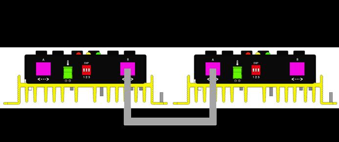
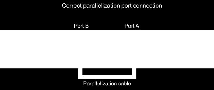
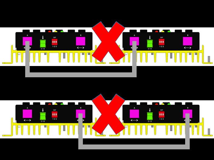
8 4. (Optional) Connect two controllers if using parallelization mode. Secure the Ethernet cable to port A of one controller and to port B of the other controller. Be sure that DIP switch 3 is on for only 1 controller. 5. Select wire type and gauge. If this GP-MPPT-40 was purchased as part of a Go Power! Solar Power Kit, appropriate wire type, gauge and length is provided. Please continue to Section 6.0, Operating Instructions. If the GP-MPPT-40 was purchased separately, follow the instructions included here. Wire type is recommended to be a stranded copper UV resistant wire. Wire fatigue and the likelihood of a loose connection are greatly reduced in stranded wire compared to solid wire. Wire gauge should be able to sustain rated current and minimize voltage drop. Wire Strip Length Strip wires 12mm. Suggested Minimum Wire Gauge (Cable length 25 ft. max. from solar array to battery bank) 50 Watt Solar Module #14 Wire Gauge 80 Watt Solar Module #12 Wire Gauge 95 Watt Solar Module #10 Wire Gauge 110 Watt Solar Module #10 Wire Gauge 125 Watt Solar Module #10 Wire Gauge 160 Watt Solar Module #10 Wire Gauge 240 Watt Solar Module #10 Wire Gauge IMPORTANT: Identify the polarity (positive and negative) on the cable used for the battery and solar module. Use colored wires or mark the wire ends with tags. Although the GP-MPPT-40 is protected, a reverse polarity contact may damage the unit. Wiring the GP-MPPT-40. Wire the GP-MPPT-40 according to the wiring schematic in Section 6.0. Run wires from the solar array and the batteries to the location of the GP-MPPT-40. Keep the solar array covered with an opaque material until all wiring is completed. 8
9 6. Torque all terminal screws according to the chart below. Connect the battery wiring to the controller first, and then connect the battery wiring to the battery. Stranded Copper 90 C Wire Terminal Screw Torque Wire Size AWG Rated Torque (in-lbs) IMPORTANT: Always use appropriate circuit protection on any conductor attached to a battery. With battery power attached, the controller should power up and display LEDs. Connect the solar wiring to the controller and remove the opaque material from the solar array. The negative solar array and battery wiring must be connected directly to the controller for proper operation. Solar array leads must only be connected to their appropriate wire terminal on the solar charge controller. Do not connect negative solar array leads to the charge controller via the vehicle chassis. 7. Mounting the GP-MPPT-40. Mount the GP-MPPT-40 to the wall using the included four mounting screws. Mount vertically for best heat dissipation. IMPORTANT: You must set the battery type on the GP-MPPT-40 before you begin to use the controller (follow steps in Section 7). The default battery setting is for AGM batteries. Congratulations, your GP-MPPT-40 should now be operational. If the battery power is low and the solar array is producing power, your battery should begin to charge. 8. Re-torque: After 30 days of operation, re-torque all terminal screws to ensure the wires are properly secured to the controller. 9


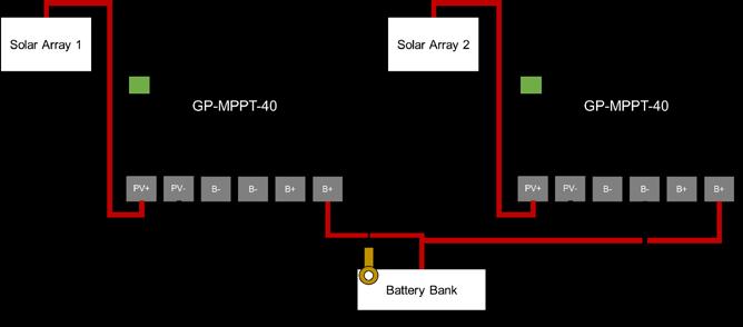
10 7.0 Wiring Diagram The GP-MPPT-40 is based on a 40 amp, 600/1200W max input from the solar modules. Use the wiring diagram to connect your battery to the battery terminals on the solar controller. First, connect the battery to the controller, and then connect the solar panel to the controller. The fuse or breaker used should be no larger than 60 amps for a standalone unit and no larger than 120 amps for two paralleled units. The controller will not work unless there is a battery connected to the battery terminals. 7.1 Stand Alone Controller 7.2 Two Paralleled Controllers The PV input on each individual controller should not exceed 150Voc, 600W for 12V, and 1200W for 24V systems. 10

11 11


12 8.0 Operating Instructions 8.1 Power Up When the GP-MPPT-40 is connected to the battery, the controller will go into Power Up Mode which takes about 10 seconds to complete. LEDs Displayed: Green and Yellow LEDs will flash briefly and then turn off for about 4 seconds. They will then stay on for about 1 second. Next they will flash quickly for a few seconds and then slowly for a few more seconds. After 10 seconds the LEDs will begin to indicator errors, charging status, and battery SOC. 8.2 Setting the Stand-alone or Parallelization Mode To select the stand-alone or parallelization mode, select the corresponding configuration of DIP switch 3. DIP switches 1 and 2 will not affect this mode. For stand-alone mode, set DIP switch 3 OFF. (factory default) For parallelization mode, select one controller to be the master controller. Set it s DIP switch 3 OFF. For the secondary slave controller, set DIP switch 3 ON. Master Slave 12
 For sealed/gel, set DIP switches 1 and 2 both ON. For flooded, set DIP switch 1 OFF and DIP switch 2 ON.")
13 8.3 Setting the Battery Charging Profile To select the battery charging profile, select the corresponding configuration of DIP switches 1 and 2. DIP switch 3 will not affect the charging profile. For AGM, set DIP switches 1 and 2 both OFF. (factory default) For sealed/gel, set DIP switches 1 and 2 both ON. For flooded, set DIP switch 1 OFF and DIP switch 2 ON. Refer to the Battery Charge Profile Chart below for details on each profile. 13
14 8.4 Battery Charging Profile Chart Battery Type Float 25 C: Values before and after the slash correspond to 12 and 24 V systems respectively. Bulk/Absorption 25 C: Set to 30 minutes every morning. Applied for 2 hours if the battery voltage drops below 12.3/24.6 volts. Equalization 25 C: Applied for 2 hours every 30 days and if the battery voltage drops below 12.1/24.2 volts. SEALED /GEL 14.1/28.2V (± 0.1/0.2V) N/A AGM 13.8/27.6V (± 0.1/0.2V) 14.4/28.8V (± 0.1/0.2V) N/A FLOODED 14.4/28.8V (± 0.1/0.2V) 14.9/29.8V (± 0.1/0.2V) The terms SEALED/GEL, AGM and FLOODED are generic battery designations. Choose the charging profile that works best with your battery manufacturer s recommendations. Auto Equalize: The GP-MPPT-40 has an automatic equalize feature that will charge and recondition your batteries once a month at a higher voltage to ensure that any excess sulfation is removed. This feature is only available when Flooded batteries are selected. 8.5 Maximum Power Boost Technology Maximum Power Boost Technology (MPBT) allows you to override the normal charging algorithm of the solar controller. MPBT is designed to be used before the end of the day if you know you will require many loads through the night. MPBT is only available with the optional remote display accessory GP- MPPT-R. Contact your dealer or call Go Power! at for ordering information. 14
15 MPBT will add 30 minutes of absorption if it triggered by the button on the remote display and there is sufficient PV power available. For example, if the Max Boost button is pressed on the remote display while the controller is performing Float charge, then the controller will try to charge at the Boost voltage for 30 minutes and then return to Float charge. IMPORTANT: Do not use the Maximum Power Boost function more than twice a day as it could damage your batteries due to gassing. 8.6 Viewing the Controller Display Information Power Up Mode: Values before and after the slash correspond to 12 and 24 V systems respectively. When the GP-MPPT-40 is connected to the battery, the controller will go into Power Up Mode which takes about 10 seconds to complete. Green and Yellow LEDs will flash briefly and then turn off for about 4 seconds. They will then stay on for about 1 second. Next they will flash quickly for a few seconds and then slowly for a few more seconds. After 10 seconds the LEDs will begin to indicator errors, charging status, and battery SOC. LEDs Displayed: Battery State of Charge (SOC): When the battery voltage falls below 12.0/24.0V, the yellow LED will turn on. When the battery voltage falls below 11.5/23.0V, the yellow LED will flash. 15
16 Battery Voltage > 12.0/24.0V: 12.0/24.0V > Battery Voltage > 11.5/23.0V: 11.5/23.0V > Battery Voltage: Charging Mode When the GP-MPPT-40 is charging, the green LED will flash. When the GP-MPPT-40 is not charging, the green LED will be on. Charging: Not Charging: 8.7 Errors Battery Over Voltage If the GP-MPPT-40 experiences a battery over voltage (15.5/31.0V), the controller will stop operating, and the display will begin to flash the green and yellow LEDs. The controller will resume operating when the error is cleared. 16
17 Battery Over Voltage: On for 1/8 second, off for 7/8 second Battery Low Voltage If the battery state of charge reaches 0%, the Yellow LED will turn on. The controller will continue operating in this condition and will only stop charging if the voltage drops below 9 volts. 11.5/23.0V > Battery Voltage: Reverse Polarity If the battery is connected with reverse polarity, the red LED will turn on. If the solar array is connected with reverse polarity while the battery is connected with correct polarity, the green and yellow LEDs will flash. Battery Reverse Polarity: Solar Array Reverse Polarity: On for 1/8 second, off for 7/8 second Solar reverse polarity will short circuit the array. This can overheat the controller and should be fixed as soon as possible. 17
18 9.0 Frequently Asked Questions (FAQs) Before a problem is suspected with the system, read this section. There are numerous events that may appear as problems but are in fact perfectly normal. Please visit gpelectric.com for the most up-to-date FAQs. It seems like my flooded batteries are losing water over time. Flooded batteries may need to have distilled water added periodically to replace fluid loss during charging. Excessive water loss during a short period of time indicates the possibility of overcharging or aging batteries. When charging, my flooded batteries are emitting gas. During charging, hydrogen gas is generated within the battery. The gas bubbles stir the battery acid allowing it to receive a fuller state of charge. Important: Ensure batteries are in a well-ventilated space Troubleshooting Problems How to Read this Section Troubleshooting Problems is split into three sub-sections, grouped by symptoms involving key components. Components considered irrelevant in a diagnosis are denoted Not Applicable (N/A). A multimeter or voltmeter may be required for some procedures listed. It is imperative all electrical precautions stated in the Warning Section and outlined in the Installation Section are followed. Even if it appears the system is not functioning, it should be treated as a fully functioning system generating live power Problems with the LED Display Display Reading: Blank (no LEDs) Time of Day: Daytime/Nighttime Possible Causes: Battery or fuse connection. 18
19 How to tell: 1. Check the voltage at the controller battery terminals with a voltmeter and compare with a voltage reading at the battery terminals. 2. If there is no voltage reading at the controller battery terminals, the problem is in the wiring between the battery and the controller. If the battery voltage is lower than 9 volts, the controller will power off. Remedy: Check all connections from the controller to the battery including checking for correct wire polarity. Check that all connections are clean, tight, and secure. Ensure the battery voltage is above 7 volts. Display Reading: Nighttime (green LED on, not flashing) Time of Day: Daytime Possible Causes: Panel is covered by something, PV panel is too dirty to supply a high enough voltage to charge the battery, PV panel is not connected. Remedy: Check the panel and to ensure it is not obscured. Clean the panel if it is dirty. Check that PV cables are connected to the controller Problems with Voltage Voltage Reading: Inaccurate (yellow LED on or flashing unexpectedly) Time of Day: Daytime/Nighttime Possible Cause: Excessive voltage drop from batteries to controller due to loose connections, small wire gauge or both. Excessive load power draw. How to tell: 1. Check the voltage at the controller battery terminals with a voltmeter and compare with the voltage reading at the battery terminals. 19
20 2. If there is a voltage discrepancy of more than 0.5 V, there is an excessive voltage drop. 3. Check the battery voltage when loads are on, and recheck the battery voltage when loads are off. If there is a voltage discrepancy of more than 1V, the loads are too large. Remedy: (2) Check all connections from the controller to the battery including checking for correct wire polarity. Check that all connections are clean, tight, and secure. Shorten the distance from the controller to battery or obtain larger gauge wire. It is also possible to double up the existing gauge wire (i.e. two wire runs) to simulate a larger gauge wire. (3) Increase the battery capacity. Consult your dealer or installer for assistance Problems with Charging Problem: Controller doesn t seem to be charging Time of Day: Daytime, clear sunny skies Possible Cause: Current is being limited as per normal operation or poor connection between solar array and controller. How to tell: 1. The green LED is flashing if charging. The green LED is on if not charging or there s insufficient solar voltage. 2. With the solar array in sunlight, check the voltage at the controller solar array terminals with a voltmeter. 3. If there is no reading at the controller solar array terminals, the problem is somewhere in the wiring from the solar array to the controller. Remedy: Check all connections from the controller to the array including checking for correct wire polarity. Check that all connections are clean, tight, and 20
21 secure. Continue with the solutions below for additional help on low current readings. Current Reading: Less than expected Time of Day: Daytime, clear sunny skies Possible Causes: (1) Current is being limited as per normal operation. (2) Incorrect series/parallel configuration and/or wiring connections and/or wire gauge. (3) Dirty or shaded module or lack of sun. (4) Blown diode in solar module when two or more modules are connected in parallel. How to tell: (2) Check that the modules and batteries are configured correctly. Check all wiring connections. (3) Modules look dirty, overhead object is shading modules or it is an overcast day in which a shadow cannot be cast. Avoid any shading no matter how small. An object as small as a broomstick held across the solar module may cause the power output to be reduced. Overcast days may also cut the power output of the module. (4) Disconnect one or both array wires from the controller. Take a voltage reading between the positive and negative array wire. A single 12 volt module should have an open circuit voltage between 17 and 22 volts. If you have more than one solar module, you will need to conduct this test between the positive and negative terminals of each module junction box with either the positive or the negative wires disconnected from the terminal. Remedy: (2) Reconnect in correct configuration. Tighten all connections. Check wire gauge and length of wire run. Refer to Suggested Minimum Wire Gauge in Section 6. (3) Clean modules, clear obstruction or wait for conditions to clear. 21
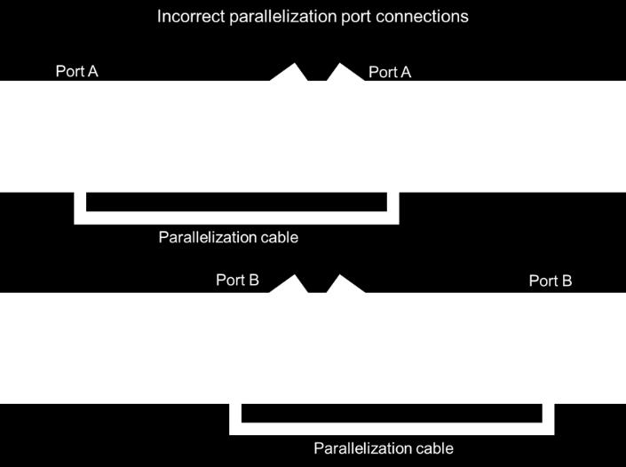
22 (4) If the open circuit voltage of a non-connected 12 volt module is lower than the manufacturer s specifications, the module may be faulty. Check for blown diodes in the solar module junction box, which may be shorting the power output of module Problems with Paralleled Controllers Problem: Green and yellow LED are flashing on one or both controllers Possible Cause: Incorrect connection between controllers, incorrect DIP switch selections How to tell: 1. Verify that port A of one controller is connected to port B of the other controller. 2. Verify that DIP switch 3 of one controller is on (up) and DIP switch 3 of the other controller is off (down). Remedy: (1) Switch Ethernet cable connections so that port A of one controller is connected to port B of the other controller. (2) Change DIP switch 3 so that for one controller it is on (up) and for the other controller is off (down) Limited Warranty 1. GoPower warrants the GP-MPPT-40 for a period of five (5) years from the date of shipment from its factory. This warranty is valid against defects in materials and workmanship for the five (5) year warranty period. It is not valid against defects resulting from, but not limited to: Misuse and/or abuse, neglect, or accident Exceeding the unit s design limits Improper installation, including, but not limited to, improper environmental protection and improper hook-up Acts of God, including lightning, floods, earthquakes, fire, and high winds 22
23 Damage in handling, including damage encountered during shipment 2. This warranty shall be considered void if the warranted product is in any way opened or altered. The warranty will be void if any eyelet, rivets, or other fasteners used to seal the unit are removed or altered, or if the unit s serial number is in any way removed, altered, replaced, defaced, or rendered illegible Repair and Return Information Visit to read the frequently asked questions section of our website to troubleshoot the problem. If trouble persists: 1. Call your Go Power! Technical Support team ( ). 2. Return defective product to place of purchase 23

24 2018 GO POWER! By Valterra Products, LLC 80636_MANUAL_GP-MPPT-40_RevA gpelectric.com 24
Owner s Manual. Solar Controller GP-PWM-30
 Owner s Manual Solar Controller GP-PWM-30 1.0 Installation Overview 1.1 Introduction A Solar Controller (or Charge Controller / Regulator) is an essential component of your photovoltaic solar system. The
GP-MPPT-R. User Manual GoPower!
 User Manual 2 Contents 1.0 Installation Overview 4 1.1 Introduction 4 1.2 Specifications 5 2.0 Warnings 6 3.0 Tools and Materials Needed 6 4.0 Choosing a Location 7 5.0 Installation Instructions 7 6.0
Solar Controller GP-PWM-30. Owner s Manual Go Power! By Valterra Power
 Solar Controller GP-PWM-30 Owner s Manual 1 2 CONTENTS 1.0 Installation Overview 4 1.1 Introduction 4 1.2 Specifications 5 2.0 Warnings 6 3.0 Tools and Materials Needed 7 4.0 Choosing a Location 7 5.0
GP-PWM-10. User Manual Carmanah Technologies Corporation
 User Manual 2 Contents 1.0 Installation Overview 4 1.1 Introduction 4 1.2 Specifications 5 2.0 Warnings 6 3.0 Tools and Materials Needed 6 4.0 Choosing a Location 7 5.0 Installation Instructions 7 6.0
Owner s Manual. Contents GP-PWM-10-SQ
 Owner s Manual Contents 1.0 Installation Overview... 2 2.0 Warnings... 2 3.0 Choosing a Location... 3 4.0 Installation Instructions... 3 5.0 Operating Instructions... 4 6.0 Frequently Asked Questions (FAQs)...
Owner s Manual. Contents GP-PWM-30-SQ GP-PWM-30-SQ
 Owner s Manual Contents 1.0 Installation Overview... 2 2.0 Warnings... 2 3.0 Choosing a Location...3 4.0 Installation Instructions... 3 5.0 Operating Instructions...4 6.0 Frequently Asked Questions (FAQs)...6
GP-PWM-30. User Manual Carmanah Technologies Corporation
 User Manual Contents 1.0 Installation Overview 3 1.1 Introduction 3 1.2 Specifications 4 2.0 Warnings 5 3.0 Tools and Materials Needed 5 4.0 Choosing a Location 6 5.0 Installation Instructions 6 6.0 Wiring
GP-PWM-10. User Manual 10 AMP PWM SOLAR CONTROLLER Go Power! By Carmanah Technologies
 GP-PWM-10 User Manual 10 AMP PWM SOLAR CONTROLLER 2015 Go Power! By Carmanah Technologies Solid Signal www.solidsignal.com info@solidsignal.com 1.877.312.4547 77726_MAN_GP-PWM-10_RevD powered by Contents
Portable Solar Kits. User Manual GP-PSK-80 GP-PSK-120
 Portable Solar Kits User Manual GP-PSK-80 GP-PSK-120 2015 Go Power! By Valterra Products, LLC Worldwide Technical Support and Product Information gpelectric.com Go Power! 201-710 Redbrick St, Victoria,
Solar Controller GP-PWM-30. Owner s Manual
 Owner s Manual 1 2 CONTENTS 1.0 Installation Overview 4 1.1 Introduction 4 1.2 Specifications 5 2.0 Warnings 6 3.0 Tools and Materials Needed 7 4.0 Choosing a Location 7 5.0 Installation Instructions 8
GP-PWM-30. User Manual 30 AMP PWM SOLAR CONTROLLER Go Power! By Carmanah Technologies
 GP-PWM-30 User Manual 30 AMP PWM SOLAR CONTROLLER 2015 Go Power! By Carmanah Technologies Solid Signal www.solidsignal.com info@solidsignal.com 1.877.312.4547 77727_MANUAL_GP-PWM-30_vE powered by Contents
PORTABLE SOLAR KITS. User Manual GP-PSK-80 GP-PSK Go Power! By Carmanah Technologies
 PORTABLE SOLAR KITS User Manual GP-PSK-80 GP-PSK-120 2016 Go Power! By Carmanah Technologies Worldwide Technical Support and Product Information gpelectric.com Carmanah Technologies Corporate Headquarters
User Manual. Solar Charge Controller 3KW
 User Manual Solar Charge Controller 3KW 1 CONTENTS 1 ABOUT THIS MANUAL... 3 1.1 Purpose... 3 1.2 Scope... 3 1.3 SAFETY INSTRUCTIONS... 3 2 INTRODUCTION... 4 2.1 Features... 4 2.2 Product Overview... 5
The Traveler Series: Wanderer
 The Traveler Series: Wanderer RENOGY 30A PWM Charge Controller Manual 2775 E. Philadelphia St., Ontario, CA 91761 1-800-330-8678 1 Version: 2.3 Important Safety Instructions Please save these instructions.
The Traveler Series: Wanderer
 The Traveler Series: Wanderer RENOGY 30A Charge Controller Manual 2775 E. Philadelphia St., Ontario, CA 91761 1-800-330-8678 Version: 2.0 Important Safety Instructions Please save these instructions. This
User Manual Solar Charge Controller 3KW
 User Manual Solar Charge Controller 3KW Version: 1.3 CONTENTS 1 ABOUT THIS MANUAL... 1 1.1 Purpose... 1 1.2 Scope... 1 1.3 SAFETY INSTRUCTIONS... 1 2 INTRODUCTION... 2 2.1 Features... 2 2.2 Product Overview...
Go Power! Manual. GPR-22 Regulator
 Go Power! Manual GPR-22 Regulator Go Power! Electric Inc. PO Box 6033 Victoria, BC V8P 5L4 Tel: 866-247-6527 Fax: 866-607-6527 Email: info@gpelectric.com Table of Contents 1. INTRODUCTION... 5 2. WARNINGS...
LS0512 Solar Charge Controller
 LandStar LS0512 Solar Charge Controller Nominal system voltage Maximum PV input voltage Nominal charge / discharge current 12VDC 35V 5A Contents 1 Important Safety Information... 1 2 General Information...
Solar Charge Controller
 Table 3: Charging voltage for 4 types of battery Battery Type Battery Type Code SC-600W MPPT Bulk Voltage Floating Voltage Vented 01 28.6 V 26.4 V Sealed 02 28.6 V 26.8 V Gel 03 28.6 V 27.4 V NiCd 04 28.6
SCC-MPPT Solar Charge Controller
 Table 3: Charging voltage for 4 types of battery Battery Battery 12V battery system 24V battery system Type Type Code Bulk Floating Bulk Floating Vented 01 14.3 V 13.2 V 28.6 V 26.4 V Sealed 02 14.3 V
SOLAR LIGHTING CONTROLLER SUNLIGHT MODELS INCLUDED IN THIS MANUAL SL-10 SL-10-24V SL-20 SL-20-24V
 SOLAR LIGHTING CONTROLLER OPERATOR S MANUAL SUNLIGHT MODELS INCLUDED IN THIS MANUAL SL-10 SL-10-24V SL-20 SL-20-24V 10A / 12V 10A / 24V 20A / 12V 20A / 24V 1098 Washington Crossing Road Washington Crossing,
Smart Battery Charger GPC-35-MAX GPC-45-MAX GPC-55-MAX GPC-75-MAX GPC-100-MAX. Owner s Manual
 Smart Battery Charger GPC-35-MAX GPC-45-MAX GPC-55-MAX GPC-75-MAX GPC-100-MAX Owner s Manual Table of Contents Important Safety Instructions 2 Features 3 Installation Guidelines 5 Warranty 8 1.0 Important
SCC-MPPT Solar Charge Controller
 Solar Charge Controller Quick Guide 200W 300W 400W 600W 850W V. 2.2 1. Introduction solar charge controller uses PWM-based DSP controller to keep the batteries regulated and prevent batteries from overcharging
SMT. Installation and Operation Manual. Model:SMT WITH MPPT TECHNOLOGY
 SMT WITH MPPT TECHNOLOGY Installation and Operation Manual Model:SMT SMT Dimensions Specification Summary System Voltage 12 V/24V Rated Battery Current 12V, 5A 8A 10A 15A 20A 25A 24V, 5A 8A 10A 15A Rated
Pure Sine Wave Inverter GP-HS1500. Owner s Manual
 Pure Sine Wave Inverter GP-HS1500 Owner s Manual 2 Table of Contents Introduction 3 Specifications 4 Name and Main Function 5 Installation 7 Operation 9 Operating Limits 13 Troubleshooting 13 Maintenance
The Traveler Series: Adventurer
 The Traveler Series: Adventurer RENOGY 30A Flush Mount Charge Controller Manual 2775 E. Philadelphia St., Ontario, CA 91761 1-800-330-8678 Version: 2.2 Important Safety Instructions Please save these instructions.
SCC-MPPT Solar Charge Controller
 Table 4: Alarm point for low battery voltage table Model Alarm point SCC-MPPT-300 10.5 V SCC-MPPT-600 21.0 V Table 5: Charging hour table for reference Battery Capacity To 90% capacity @ 25A charging current
LIGHTNING PROTECTION UNIT (LPU)
") LIGHTNING PROTECTION UNIT (LPU) Photovoltaic Lightning Protection Device Installation and Operation Manual SPECIALTY CONCEPTS, INC. 8954 Mason Ave. Chatsworth, CA 91311 USA MODELS COVERED: LPU-50, LPU-150,
LIGHTNING PROTECTION UNIT (LPU) Photovoltaic Lightning Protection Device Installation and Operation Manual SPECIALTY CONCEPTS, INC. 8954 Mason Ave. Chatsworth, CA 91311 USA MODELS COVERED: LPU-50, LPU-150,
The Traveler Series TM : Adventurer
 The Traveler Series TM : Adventurer 30A PWM Flush Mount Charge Controller w/ LCD Display 2775 E. Philadelphia St., Ontario, CA 91761 1-800-330-8678 Version: 3.4 Important Safety Instructions Please save
LS0512R Solar Light Controller
 LandStar LS0512R Solar Light Controller Nominal system voltage Maximum PV input voltage Nominal charge / discharge current 12VDC 35V 5A Contents 1 Important Safety Information... 1 2 General Information...
12 VOLT 30 AMP DIGITAL SOLAR CHARGE CONTROLLER
 12 VOLT 30 AMP DIGITAL SOLAR CHARGE CONTROLLER User s Manual Congratulations on your Coleman solar product purchase. This product is designed to the highest technical specifications and standards. It will
Installation and Operating Instructions. MPPT Solar System Controller ISC3040
 Installation and Operating Instructions MPPT Solar System Controller ISC3040 ABOUT THIS MANUAL These operating instructions come with the product and should be kept with it as a reference to all user s
Photovoltaic Battery Charge Controller Installation & Operation Manual Mason Ave. Chatsworth, Ca USA
 SPECIALTY CONCEPTS Mark III/ 15 (SC3/ 15) Photovoltaic Battery Charge Controller Installation & Operation Manual SPECIALTY CONCEPTS, INC. 8954 Mason Ave. Chatsworth, Ca 91311 USA Copyright 9 / 1997 Specialty
Transfer Switch GPTS 30
 Transfer Switch GPTS 30 Owner s Manual Table of Contents Introduction 2 Installation 3 Operational Testing 7 Troubleshooting 8 Hi-Pot Testing 9 Generator Note 10 Medical Appliances 10 Caution 10 Warranty
Art. No. EC-315. Art. No. EC-330. Art. No. EC-340 SWITCH-MODE BATTTERY CHARGER CONTENTS IMPORTANT SAFETY PRECAUTIONS... 2
 SWITCH-MODE BATTTERY CHARGER CONTENTS IMPORTANT SAFETY PRECAUTIONS... 2 DESCRIPTION AND FEATURES... 3 CHARGING STAGES... 4 Art. No. EC-315 Art. No. EC-330 Art. No. EC-340 PROTECTIONS... 5 INSTALLATION...
Installation and Operation Manual. Dual Battery Charging Solar Controller. for RVs, Caravans, and Boats. Ratings. Rated Solar Current 25 Amps
 SUNSAVER DUO TM Installation and Operation Manual. Dual Battery Charging Solar Controller for RVs, Caravans, and Boats.. Ratings Nominal Voltage 12 Volts Rated Solar Current 25 Amps 1098 Washington Crossing
PHOTOVOLTAIC SYSTEM CONTROLLERS SUNSAVER MODELS INCLUDED IN THIS MANUAL SS-6 / SS-6L SS-10 / SS-10L SS-10-24V / SS-10L-24V SS-20L SS-20L-24V
 PHOTOVOLTAIC SYSTEM CONTROLLERS OPERATOR S MANUAL SUNSAVER MODELS INCLUDED IN THIS MANUAL SS-6 / SS-6L SS-10 / SS-10L SS-10-24V / SS-10L-24V SS-20L SS-20L-24V 6A / 12V 10A / 12V 10A / 24V 20A / 12V 20A
SOLAR ALL ELECTRIC KITS
 SOLAR ALL ELECTRIC KITS User Manual SOLAR-AE4 SOLAR-AE6 2018 Go Power! Worldwide Technical Support and Product Information gpelectric.com Go Power! Headquarters #201-710 Redbrick St., Victoria, BC Canada
Duo Battery Charge Controller
 Duo Battery Charge Controller RENOGY 10A 20A Pulse Width Modulation Solar Charge Controller Manual 1 2775 E. Philadelphia St., Ontario CA 91761 1-800-330-8678 Version: 1.2 Important Safety Instructions
WITH TRAKSTAR TM MPPT TECHNOLOGY. Installation and Operation Manual. Model: SS-MPPT-15L
 SUNSAVER MPPT TM WITH TRAKSTAR TM MPPT TECHNOLOGY Installation and Operation Manual MAXIMUM POWER POINT TRACKING Model: SS-MPPT-15L 1098 Washington Crossing Road Washington Crossing, PA 18977 USA www.morningstarcorp.com
SOLAR FLEX-500 KIT. User Manual Go Power! Worldwide Technical Support and Product Information gpelectric.com
 SOLAR FLEX-500 KIT User Manual 2018 Go Power! Worldwide Technical Support and Product Information gpelectric.com Go Power! Headquarters #201-710 Redbrick St., Victoria, BC Canada V8T 5J3 Tel: 1.866.247.6527
BZ Products Inc. U.S.A.
 BZ Products Inc. U.S.A. Model MPPT 150/50 Installation Instructions Thank you for choosing BZ Products MPPT 150/50. Made entirely in the USA, operation of this unit is fully automatic, and works in conjunction
12/24 VOLT AUTOMATIC SOLAR CHARGE CONTROLLER
 12/24 VOLT AUTOMATIC SOLAR CHARGE CONTROLLER P/No.s SC320 & SC330 WARNING Please read these instructions completely prior to installation. Lead acid batteries can be dangerous. Ensure no sparks or flames
IV. PROOF OF PURCHASE: A warranty claim must be accompanied by proof of the date of purchase.
 PD9100 / 9200 SERIES POWER CONVERTER OWNERS MANUAL PROGRESSIVE DYNAMICS, INC. POWER CONVERTER LIMITED WARRANTY I. LIMITED WARRANTY: Progressive Dynamics, Inc. warrants its power converter to be free from
ECO SOLAR POWER KITS. User Manual GP-ECO-10 GP-ECO-20 GP-ECO Go Power! Worldwide Technical Support and Product Information gpelectric.
 ECO SOLAR POWER KITS User Manual GP-ECO-10 GP-ECO-20 GP-ECO-80 2018 Go Power! Worldwide Technical Support and Product Information gpelectric.com Go Power! Headquarters #201-710 Redbrick St., Victoria,
Installation and Operating Instructions. Solar System Controller ISC3020
 Installation and Operating Instructions Solar System Controller ISC3020 ABOUT THIS MANUAL These operating instructions come with the product and should be kept with it as a reference to all user s of
SOLAR FLEX KITS. User Manual GP-FLEX-30 GP-FLEX-50 GP-FLEX-50E GP-FLEX-100 GP-FLEX-100E GP-FLEX-200
 SOLAR FLEX KITS User Manual GP-FLEX-30 GP-FLEX-50 GP-FLEX-50E GP-FLEX-100 GP-FLEX-100E GP-FLEX-200 2018 Go Power! Worldwide Technical Support and Product Information gpelectric.com Go Power! Headquarters
Eclipse Solar Suitcase
 Eclipse Solar Suitcase Renogy 100W 200W 2775 E. Philadelphia St., Ontario, CA 91761 1-800-330-8678 Version 1.0 Important Safety Instructions Please save these instructions. This manual contains important
3.1 General Information
 1.0 Important Safety Information 2.0 General Information 2.1 Overview 2.3 Features 4 5 5 5 3.0 Installation 3.1 General Information 3.2 Wiring 4.0 Operation 4.1 MPPT Technology 13 4.2 Battery Charging
Rover Series. Rover 20A 40A Maximum Power Point Tracking Solar Charge Controller
 Rover Series Rover 20A 40A Maximum Power Point Tracking Solar Charge Controller 0 2775 E. Philadelphia St., Ontario, CA 91761 1-800-330-8678 Version 1.5 Important Safety Instructions Please save these
PHOTO VOLTAIC CHARGE MODULE MULTI POINT TRACKING
 FEATURES Multi Point Tracking (MPT)/ Pulse Width Modulation (PWM) is a six stage solar charge controller. Drop-in PWM replacement for the PVCM-25D two stage solar charge controller. Works with the PVDM4-LC,
RUTLAND HRDi CHARGE REGULATOR INSTALLATION AND OPERATION
 RUTLAND HRDi CHARGE REGULATOR INSTALLATION AND OPERATION Introduction Congratulations and thank you for purchasing Marlec s HRDi Charge Regulator. This is the latest technology for charge regulation of
Solar System Controller
 POWER FAULT 50 Amp MPPT Installation and Operating Instructions Solar System Controller ISC5040 ABOUT THIS MANUAL These operating instructions come with the product and should be kept with it as a reference
GV-4 Manual 4A / 50W IMPORTANT SAFETY INSTRUCTIONS SAVE THESE INSTRUCTIONS. Solar Charge Controller with Maximum Power Point Tracking.
 GV-4 Manual Solar Charge Controller with Maximum Power Point Tracking For models: GV-4-Pb-12V: 12V Lead-Acid/AGM/Gel/Sealed/Flooded http://genasun.com Genasun Inc. 1035 Cambridge st. Suite 16B Cambridge,
10A / 15A / 20A Solar Charge Controller. PU1024 / PU1524 / PU2024 series INSTRUCTION MANUAL
 10A / 15A / 20A Solar Charge Controller PU1024 / PU1524 / PU2024 series INSTRUCTION MANUAL Dear Customer, Thank you very much for choosing our product. This manual contains important information about
AUTO CHARGE 4000 MODEL #: LOW PROFILE CHARGER AUTOMATIC DUAL OUTPUT BATTERY CHARGER INSTRUCTION MANUAL
 INSTRUCTION MANUAL AUTO CHARGE 4000 LOW PROFILE CHARGER AUTOMATIC DUAL OUTPUT BATTERY CHARGER Unit supplied with this display MODEL #: 091-89-12 INPUT: 120 Volt, 50/60 Hz, 5 Amps OUTPUT: 45 Amps File:
Installation and operating instructions. Solar charge controller MPPT 10 A / 20 A Z Z
 Installation and operating instructions Solar charge controller MPPT 10 A / 20 A EN 1 Contents 1. About these instructions... 3 1.1 Applicability... 3 1.2 Users... 3 1.3 Description of symbols... 3 2.
KIT-STCS60D KIT-STCS100D Solar Suitcase 60W and 100W Owner s Manual
 KIT-STCS60D KIT-STCS100D Solar Suitcase 60W and 100W Owner s Manual RNG Group Inc. (Renogy) 14288 Central Ave., Suite A Chino, CA 91710 1-800-330-8678 Product Description The Renogy Solar Suitcases combine
ACC Series Power Conditioner OPERATION & INSTALLATION MANUAL
 ACC Series Power Conditioner OPERATION & INSTALLATION MANUAL PHASETEC digital power conditioners are designed to safely operate electrical equipment in the harshest power quality environments. With a wide
OD10 10A Outdoor Solar Charge Controller
 OD10 10A Outdoor Solar Charge Controller CHC-OD12-10 User s Manual Page 1 of 14 windynation Revision 2 Table of Contents 1.1 Features...3 1.2 Safety Information...4 1.3 Specifications...4 1.3.1 Electrical
Automatic Battery Charger Switching mode with Micro-controlled Input: Vac / Output: 12Volt DC
 Automatic Battery Charger Switching mode with Micro-controlled Input:220-260Vac / Output: 12Volt DC User s Manual and Important Safety Information Model: OC-SW121080 / OC-SW121160 / OC-SW121210 FEATURES
User Manual 1KVA-5KVA (PF1) INVERTER / CHARGER. Version: 1.0
 INVERTER / CHARGER. Version: 1.0") User Manual 1KVA-5KVA (PF1) INVERTER / CHARGER Version: 1.0 Table Of Contents ABOUT THIS MANUAL... 1 Purpose... 1 Scope... 1 SAFETY INSTRUCTIONS... 1 INTRODUCTION... 2 Features... 2 Basic System Architecture...
User Manual 1KVA-5KVA (PF1) INVERTER / CHARGER Version: 1.0 Table Of Contents ABOUT THIS MANUAL... 1 Purpose... 1 Scope... 1 SAFETY INSTRUCTIONS... 1 INTRODUCTION... 2 Features... 2 Basic System Architecture...
Transfer Switch TS-50. Owner s Manual
 Transfer Switch TS-50 Owner s Manual Table of Contents Introduction 2 Installation 2 Operational Testing 7 Troubleshooting 7 Hi-Pot Testing 8 Generator Note 9 Medical Appliances 10 Caution 10 Disclaimer
Installation and Operating Instructions. Solar System Controller ISC3030
 Installation and Operating Instructions Solar System Controller ISC3030 ABOUT THIS MANUAL These operating instructions come with the product and should be kept with it as a reference to all user s of the
Solar Hybrid Inverter SP Brilliant Series
 User Manual Solar Hybrid Inverter SP Brilliant Series Version: 1.5 Table Of Contents ABOUT THIS MANUAL... 1 Purpose... 1 Scope... 1 SAFETY INSTRUCTIONS... 1 INTRODUCTION... 2 Features... 2 Basic System
Automatic Battery Charger Switching mode with Micro-controlled Input: Vac / Output: 12Volt DC
 Automatic Battery Charger Switching mode with Micro-controlled Input:220-260Vac / Output: 12Volt DC User s Manual and Important Safety Information Model: OC-SW121080 / OC-SW121160 / OC-SW121210 FEATURES
User s Manual. Automatic Switch-Mode Battery Charger
 User s Manual Automatic Switch-Mode Battery Charger IMPORTANT Read, understand, and follow these safety rules and operating instructions before using this battery charger. Only authorized and trained service
User Manual 5KVA/5KW INVERTER / CHARGER. Version: 1.3
 User Manual 5KVA/5KW INVERTER / CHARGER Version: 1.3 Table Of Contents ABOUT THIS MANUAL... 1 Purpose... 1 Scope... 1 SAFETY INSTRUCTIONS... 1 INTRODUCTION... 2 Features... 2 Basic System Architecture...
PV Charge Controller SBC-7108 / 7112 / 7120
 PV Charge Controller SBC-7108 / 7112 / 7120 User's Manual NOTE: Please note that features like LCD read out of AH logging of 3 days (see Section 3.3) and 10 Night-light mode (see Section 4.3) are available
GV-10 Manual 10.5A / 140W IMPORTANT SAFETY INSTRUCTIONS SAVE THESE INSTRUCTIONS. Solar Charge Controllers with Maximum Power Point Tracking
 GV-10 Manual Solar Charge Controllers with Maximum Power Point Tracking For models: GV-10-Pb-12V: GV-10-Pb-CV: 12V Lead-Acid/AGM/Gel/Sealed/Flooded 12V Custom Multi-Stage Lead-Acid/AGM/Gel/ Sealed/Flooded
1KVA/ 2KVA/ 3KVA/ 4KVA/ 5KVA MS, LV MPPT INVERTER / CHARGER. User Manual. Version: 2.3
 1KVA/ 2KVA/ 3KVA/ 4KVA/ 5KVA MS, LV MPPT INVERTER / CHARGER User Manual Version: 2.3 Table Of Contents ABOUT THIS MANUAL... 1 Purpose... 1 Scope... 1 SAFETY INSTRUCTIONS... 1 INTRODUCTION... 2 Features...
SBC / 2140 / Stage Battery Charger User Manual
 SBC - 2130 / 2140 / 2150 3 Stage Battery Charger User Manual Keep this manual in a safe place for quick reference at all times. This manual contains important safety and operation instructions for correct
NSTHAI. Solar Light Controller
 NSTHAI Design patent NO.: 201130028317.3 Utility model patent NO.:201120064092.1 NSC2024R (LS2024R) Solar Light Controller INSTRUCTION MANUAL Thank you very much for selecting our product! This manual
Manual Installation & Operation
 Manual Installation & Operation Model: NCxxLxx 12A or 30A Solid State Solar Charging Regulator and 12A Load Controller. 231 Patent #: 5,642,030 Applies Page 1 Warnings When Installing, connect grounds,
Solar Differential Temperature Controller Model DTC-D
 OVERVIEW The DTC-D is specifically designed for solar heating applications where the collector circulation pump is powered from a solar (PV) panel, or optionally, battery power or any 12VDC source. Its
PUMP PLUS 2000 PLC MODEL #: PP AUTOMATIC DUAL OUTPUT BATTERY CHARGER INSTRUCTION MANUAL
 INSTRUCTION MANUAL PUMP PLUS 2000 PLC AUTOMATIC DUAL OUTPUT BATTERY CHARGER Supplied with Dual Bar Graph Display MODEL #: 091-237-12-PP INPUT: 120 Volt, 60 Hz, 3.5 Amps OUTPUT BATTERY 1 and 2: 15 or 18
LPC 40 MODEL #: LOW PROFILE CHARGER WITH PLC AUTOMATIC SINGLE OUTPUT BATTERY CHARGER INSTRUCTION MANUAL
 INSTRUCTION MANUAL LPC 40 LOW PROFILE CHARGER WITH PLC AUTOMATIC SINGLE OUTPUT BATTERY CHARGER Unit supplied with one of these displays MODEL #: 091-200-12 INPUT: 120 Volt, 50/60 Hz, 5 Amps OUTPUT: 40
LS1024R / LS1524R / LS2024R. Solar Light Controller INSTRUCTION MANUAL
 EPSOLAR Design patent NO.: 201130028317.3 Utility model patent NO.: 201120064092.1 LS1024R / LS1524R / LS2024R Solar Light Controller INSTRUCTION MANUAL Thank you very much for selecting our product! This
Phocos CML-V2. Solar charge controller. User Manual (English) Dear customer,
 Dear customer,") Phocos CML-V2 Solar charge controller User Manual (English) Dear customer, Thank you very much for buying this Phocos product. Please read the instructions carefully and thoroughly before using the product.
Phocos CML-V2 Solar charge controller User Manual (English) Dear customer, Thank you very much for buying this Phocos product. Please read the instructions carefully and thoroughly before using the product.
PUMP PLUS 1000 PLC MODEL #: PP AUTOMATIC SINGLE OUTPUT BATTERY CHARGER INSTRUCTION MANUAL
 INSTRUCTION MANUAL PUMP PLUS 1000 PLC AUTOMATIC SINGLE OUTPUT BATTERY CHARGER Unit supplied with one of these displays MODEL #: 091-215-12-PP INPUT: 120 Volt, 60 Hz, 3.5 Amps OUTPUT BATTERY 1 and 2: 15
User Manual 1.5KVA-3KVA INVERTER / CHARGER. Version: 1.1
 User Manual 1.5KVA-3KVA INVERTER / CHARGER Version: 1.1 Table Of Contents ABOUT THIS MANUAL... 1 Purpose... 1 Scope... 1 SAFETY INSTRUCTIONS... 1 INTRODUCTION... 2 Features... 2 Basic System Architecture...
TRACER 1206/1210/1215
 TRACER 1206/1210/1215 Maximum Power Point Tracking Controller Installation and Operation Manual Thanks very much for selecting our products! This manual offers important information and suggestions with
User manual. Solar Hybrid 1-5KVA. Uninterruptible Power Supply / Charger
 User manual Solar Hybrid 1-5KVA Uninterruptible Power Supply / Charger All rights reserved. The information in this document is subject to change without notice. Thank you for purchasing this series UPS.
Photovoltaic Battery Charge Controller Installation And Operation Manual Mason Ave. Chatsworth, CA USA
 SPECIALTY CONCEPTS SYSTEM (SCS/ 50, SCS/ 90) Photovoltaic Battery Charge Controller Installation And Operation Manual SPECIALTY CONCEPTS, INC. 8954 Mason Ave. Chatsworth, CA 91311 USA Copyright 10 / 1997
The Ideal Charge Controller for Home, RV & Marine Solar Systems
 The Ideal Charge Controller for Home, RV & Marine Solar Systems The Sunsei TM CC20000D is a highly reliable charge controller that is ideal for the Sunsei TM SolarCharger SE-4000, SE-6000 and SE-8000 solar
User Manual. Energy charged in battery. 30% than conventional solar charger. Solar charge controller
 User Manual Energy charged in battery MPPT Solar charge controller 30% than conventional solar charger SUN-MPPT-3015A SUN-MPPT-5015A 1 2 List: Dimensions in Millimeters [Inches]... 4 1.0 Important Safety
GP-PWM-30-SB. User Manual 30 AMP PWM SOLAR CONTROLLER Go Power!
 GP-PWM-30-SB User Manual 30 AMP PWM SOLAR CONTROLLER Contents 1.0 Installation Overview 3 1.1 Introduction 3 1.2 System Voltage and Current 3 1.3 Battery Type 3 1.4 Low Voltage Disconnect Function (USB
General Installation Manual Mar 2009, Sanyo Electric Co., Ltd. All Rights Reserved 3/23/09
 General Installation Manual General Installation Manual for SANYO HIT Photovoltaic Modules. Please read this manual completely before installation or use of SANYO modules. This manual applies to the following
Pure Sine Wave Inverter Charger
 Pure Sine Wave Inverter Charger Renogy 1000W 2000W Pure Sine Wave Inverter Charger Manual 2775 E. Philadelphia St., Ontario, CA 91761 1-800-330-8678 Version 1.6 1 Important Safety Instructions Please save
CLEAN POWER TM CPS Series Operator s Manual
 12 Test Equipment CLEAN POWER TM CPS Series Operator s Manual Power Supply / Maintenance Charger for 12 Volt Systems The CPS series of power supplies / maintenance chargers are the ultimate in supplying
General Installation Manual July 1, SANYO Energy (USA) Corp. All Rights Reserved.
 Corp. All Rights Reserved.") General Installation Manual for SANYO HIT Photovoltaic Modules. Please read this manual completely before use of, or installation of HIT Power modules. This manual applies to the following models: HIT
General Installation Manual for SANYO HIT Photovoltaic Modules. Please read this manual completely before use of, or installation of HIT Power modules. This manual applies to the following models: HIT
ST Charger. Industrial Battery Charger
 ST Charger Industrial Battery Charger Installation and Operation Manual ST_13 Table of Contents Pg# 1.0 INSTALLATION 1 1.1 Receiving 1 1.2 Location 1 1.3 Line Voltage 1 1.4 A.C. Service Requirements 2
LS1024BP/ LS2024BP. Solar Charge Controller USER MANUAL
 EPSOLAR LS1024BP/ LS2024BP Solar Charge Controller USER MANUAL Thank you very much for selecting our product! This manual offers important information and suggestions with respect to installation, use
User Manual 1.5KVA-3KVA INVERTER / CHARGER
 User Manual 1.5KVA-3KVA INVERTER / CHARGER Version: 1.0 Table Of Contents ABOUT THIS MANUAL... 1 Purpose... 1 Scope... 1 SAFETY INSTRUCTIONS... 1 INTRODUCTION... 2 Features... 2 Basic System Architecture...
Your new LM controller is a state-of-the art device which was developed in accordance with the latest
 CAP LM-series Solar charge controller User Manual Thank you very much for buying this CAP product. Please read the instructions carefully and thoroughly before using the products. Your new LM controller
MPPT SOLAR CONTROLLER FOR MODELS: 20A baterai 12V 24V
 Main Features MPPT SOLAR CONTROLLER FOR MODELS: 20A baterai 12V 24V 20A MPPT solar charge controller MPPT technology Built-in DSP controller with high performance Automatic battery voltage detection for
MPPT Controller PVTS Series User Manual. User Manual. 800W-4000W Hybrid solar inverter. Version: 1.4
 User Manual 800W-4000W Hybrid solar inverter Version: 1.4 Table Of Contents ABOUT THIS MANUAL... 1 Purpose... 1 Scope... 1 SAFETY INSTRUCTIONS... 1 INTRODUCTION... 2 Features... 2 Basic System Architecture...
User Manual 1KVA-5KVA INVERTER / CHARGER
 User Manual 1KVA-5KVA INVERTER / CHARGER Version: 1.7 Table Of Contents ABOUT THIS MANUAL... 1 Purpose... 1 Scope... 1 SAFETY INSTRUCTIONS... 1 INTRODUCTION... 2 Features... 2 Basic System Architecture...
Owner s Manual. Expansion Kits: GP-RV-80E GP-RV-95E GP-RV-160E
 powered by Expansion Kits: GP-RV-8E GP-RV-E RV Power Kits: GP-RV-8 GP-RV- Weekender SW Owner s Manual shown here GP-RV-8E GP-RV-E GP-RV-8 GP-RV- Standard Kits Expansion Kits PART GP-RV-8/95/ * or SW *
MPPT Solar Charge Controller
 MPPT Solar Charge Controller Installation and Operation Manual Maximum Power Point Tracking Technology Content 1. IMPORTANT SAFETY INSTRUCTIONS......3 2. GETTING STARTED..... 5 3. INSTALLATION... 8 4.