User Manual. Energy charged in battery. 30% than conventional solar charger. Solar charge controller
|
|
|
- Cecilia Dickerson
- 6 years ago
- Views:
Transcription

1 User Manual Energy charged in battery MPPT Solar charge controller 30% than conventional solar charger SUN-MPPT-3015A SUN-MPPT-5015A 1
2 2
3 List: Dimensions in Millimeters [Inches] Important Safety Information General Information Overview Features Installation General Information Wiring MPPT Technology Battery Charging Information LED Indications Setting operation Warranty Specifications
4 Dimensions in Millimeters [Inches] 4
5 1.0 Important Safety Information Save These Instructions This manual contains important safety, installation and operating instructions for the MPPT solar controller. The following symbols are used throughout this manual to indicate potentially dangerous conditions or mark important safety instructions: WARNING: Indicates a potentially dangerous condition. Use extreme caution when performing this task. CAUTION: Indicates a critical procedure for safe and proper operation of the controller. NOTE: Indicates a procedure or function that is important for the safe and proper operation of the controller. General Safety Information Read all of the instructions and cautions in the manual before the beginning of installation. MPPT contains no user-serviceable parts.do not disassemble or attempt to repair the controller. Disconnect all sources of power to the controller before installing or adjusting the MPPT. There are no fuses or disconnects inside the MPPT. Do not attempt to repair it. Install external fuses/breakers as required. 5

6 2.0 General Information 2.1 Overview Thank you for selecting the MPPT solar charge controller.the MPPT is essentially a smart DC to DC converter which has been optimized to harvest maximum energy from the PV array in battery based solar electric systems by using a variety of maximum power point tracking (MPPT) strategies. The controller s secondary objective is to ensure that the batteries receive a full charge without becoming overcharged. This is accomplished through a four stage charging process. Please take the time to read this operator s manual and be familiar with the controller.this will help you make full use of the many advantages the MPPT can provide for your PV system. 2.2 Features 1 - Battery Status LED Indicator:An LED indicator that shows battery status or system errors. 2 - Charging Status LED Insdicator:An LED indicator that shows charging status and overvoltage of pv. 3 - Setting Button1:Set load work mode,battery type and max charge current. 4 - Setting Button2:Set load work mode,battery type and max charge current(in manual mode used for load ON/OFF). 5 - LCD Digital Display:Dispaly the system status 6 - Wiring Box Cover:Sheet metal wiring box cover protects power connections 7 - FAN:FAN to dissipate Internal circuit heat 8 - Heatsink:Aluminum heatsink to dissipate controller heat 9 - Mounting Hanger:Keyhole slot for mounting 10 - Solar Module Terminals:Connect solar modules 11 - Battery Terminals:Connect batteries 12 - Load Terminals:Connect loads 13 - RJ45 Communication Interface:Communicate with personal computer 6
7 3.0 Installation 3.1 General Information The mounting location is important to the performance and operating life of the controller. The environment must be dry and protected from water ingress. If required, the controller may be installed in a ventilated enclosure with sufficient air flow. Never install the MPPT unit in a sealed enclosure. The controller may be mounted in an enclosure with sealed batteries, but never with vented/ flooded batteries. Battery fumes from vented batteries will corrode and destroy the MPPT circuits. Multiple MPPT can be installed in parallel on the same battery bank to achieve higher charging current. Additional parallel controllers can also be added in the future. Each MPPT must have its own solar array. CAUTION: Equipment Damage or Risk of Explosion Never install the MPPT in an enclosure with vented/flooded batteries. Battery fumes are fl ammable and will corrode and destroy the MPPT circuits. CAUTION: Equipment Damage When installing the MPPT in an enclosure, ensure suffi cient ventilation. Installation in a sealed enclosure will lead to over-heating and a decreased product lifetime. NOTE : Mounting When mounting the MPPT,ensure free air through the controller heat sink fins. There should be at least 150mm of clearance above and below the controller to allow for cooling. If mounted in an enclosure, ventilation is highly recommended. 7
8 3.2 Wiring Step 1 - Mount to a Vertical Surface Attach the mounting hanger to the bottom of the MPPT with the M6 screw provided as shown in figure
9 2. Place the MPPT on a vertical surface protected from direct sunlight, high temperatures, and water. The MPPT requires at least 150 mm of clearance right and left. flow as shown in figure 3-2 below. 9
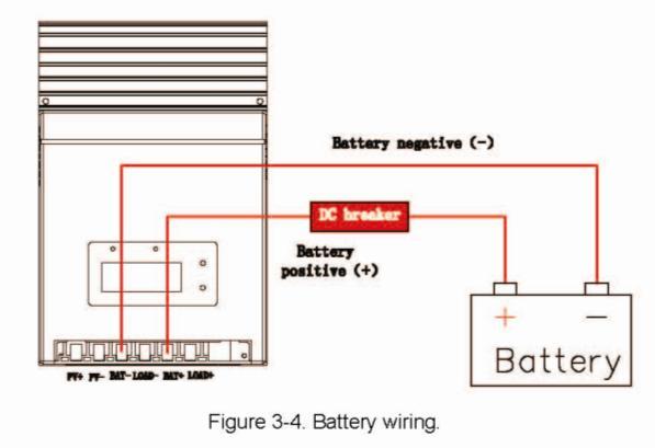
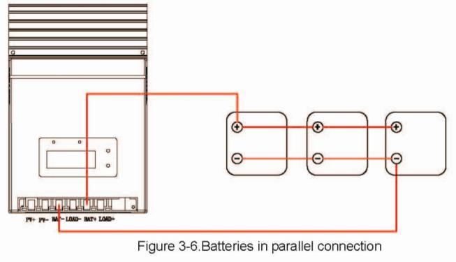
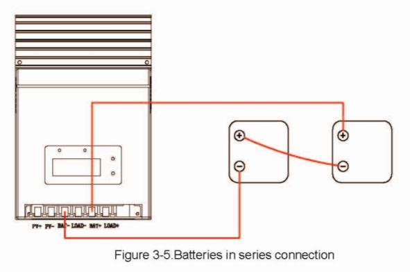
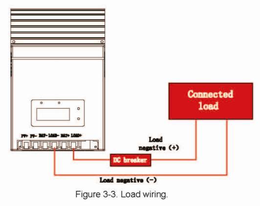
10 Step 2: DC load Wiring (Refer to Fig.3-3) WARNING:Please use the appropriate cable size according to load rating. Please refer to important Safety Warnings Section for the details. It will prevent internal high temperature. The load output will provide battery voltage to connected loads such as lights,monitors and other electronic devices. connect load positive(+) wire to the positive terminal of the unit and load negative(-) wire to the negative terminal of the unit. install a DC Breaker or a DC fuse holder in a positive wire. The rating of the DC Breaker/Fuse must be rated to 125% of the maximum load current or more. Keep the DC breaker off or do not install the DC fuse. See Section 4.3 Setting Operation for more detials about load control. Step 3: Battery Wiring (Refer to Fig.3-4) WARNING: Risk of explosion or fire! Never short circuit positive(+) and negative(-) or cables connect battery positive(+) wire to the positive terminal of the unit and battery negative(-) wire to the negative terminal of the unit. Use #6 to #7 AWG wire rated for 75ºC for Battery connections. install a DC Breaker or a DC fuse holder in a positive wire. The rating of the DC Breaker/Fuse must be rated to 125% of the maximum charging current or more. Keep the DC breaker off or do not install the DC fuse. 1) Multiple batteries in series connection (Refer to Fig.3-5): All batteries must be equal in voltage and amp hour capacity. The sum of their voltage must be equal to the nominal DC Voltage of the unit. 2) Multiple batteries in parallel connection(refer to Fig.3-6): Each battery s voltage must be equal to the Nominal DC Voltage of the unit. 10
11 11
 Multiple solar modules in series connection(refer to Fig.3-7): All modules must be equal in voltage.")
 wire to the positive terminal of the unit and soalrmodule negative(-) wire to the negative terminal of the unit.")
12 Step 4: Solar Module Wiring WARNING: Risk of electric shock! Exercise caution when handing solar wiring. The solar array high voltage output can cause severe shock or injury. Cover modules form the sunlight before installing solar panel wiring. 1) Multiple solar modules in series connection(refer to Fig.3-7): All modules must be equal in voltage.the sum if their voltage must be equal to the nominal DC Voltage of the unit. The sum of their solar power must exceed the maximum capacity of the unit. connect soalr module positive(+) wire to the positive terminal of the unit and soalrmodule negative(-) wire to the negative terminal of the unit. Use #6 to #7 AWG wirerated for 75ºC for Solar connections. 12
 Step 5: Switch on DC breaker or install DC fuse After completing all wires,double check if all wires are")
13 2) Multiple solar modules in parallel connection(refer to Fig.7): Each module s voltage must be equal to the nominal DC Voltage of the unit. The sum of their solar power must exceed the maximum capacity of the unit(see below Table 3-1) Step 5: Switch on DC breaker or install DC fuse After completing all wires,double check if all wires are connected well. Then switch on DC breaker or install DC fuse on. Take off the cover of solar module. When the solar module power is above 15V, the charge will automatically turn on to work. 13
14 4.0 Operation The MPPT operation is fully automatic. After installation is completed, there are few operator tasks to perform. However, the operator should be familiar with the operation and care of the MPPT as described in this section. 4.1 MPPT Technology MPPT stands for "Maximum Power Point Tracking". This describes a process by means of which the solar module is always operated at the point of maximum possible power. Because the point the maximum power can vary depending on the operating mode and the local conditions, and because it changes in the course of the day, the term "tracking" is used, i.e. the tracking of this point. Current Boost Under most conditions, MPPT technology will boost the solar charge current. For example, a system may have 36 Amps of solar current flowing into the MPPT and 44 Amps of charge current flowing out to the battery.the MPPT does not create current! Rest assured that the power into the MPPT is the same as the power out of the MPPT. Since power is the product of voltage and current (Volts x Amps), the following is true*: (1) Power Into the MPPT = Power Out of the MPPT (2) Volts In x Amps In = Volts Out x Amps Out * assuming 100% efficiency. Losses in wiring and conversion exist. If the solar module s maximum power voltage (Vmp) is greater than the battery voltage, it follows that the battery current must be proportionally greater than the solar input current so that input and output power are balanced. The greater the difference between the Vmp and battery voltage, the greater the current boost. Current boost can be substantial in systems where the solar array is of a higher nominal voltage than the battery. An Advantage Over Traditional Controllers Traditional controllers connect the solar module directly to the battery when recharging. This requires that the solar module operate in a voltage range that is usually below the module s Vmp. In a 12 Volt system for example, the battery voltage may range from Vdc, but the module s Vmp is typically around 16 or 17 Volts. Figure 4-1 shows typical current vs. voltage and power output curves for a nominal 12 Volt off-grid module. 14
15 The array Vmp is the voltage where the product of output current and voltage (Amps x Volts) is greatest, which falls on the knee of the solar module I-V curve as shown on the left in Figure 4-1. Because traditional controllers do not always operate at the Vmp of the solar array, energy is wasted that could otherwise be used to charge the battery and power system loads. The greater the difference between battery voltage and the Vmp of the module, the more energy is wasted. MPPT technology will always operate at the maximum power point resulting in less wasted energy compared to traditional controllers. Conditions That Limit the Effectiveness of MPPT The Vmp of a solar module decreases as the temperature of the module increases. In very hot weather, the Vmp may be close or even less than battery voltage. In this situation, there will be very little or no MPPT gain compared to traditional controllers. However, systems with modules of higher nominal voltage than the battery bank will always have an array Vmp greater than battery voltage. Additionally, the savings in wiring due to reduced solar current make MPPT worthwhile even in hot climates. 15
16 Equalize Stage WARNING: Risk of Explosion Equalizing vented batteries produces explosive gases. The battery bank must be properlyventilated. CAUTION: Equipment Damage Equalization increases the battery voltage to levels that may damage sensitive DC loads. Verifyall system loads are rated for the temperature compensated Equalize voltage before beginning an Equalization charge. CAUTION: Equipment Damage Excessive overcharging and gassing too vigorously can damage the battery plates and cause shedding of active material from the plates. An equalization that is too high or for too long can be damaging. Review the requirements for the particular battery being used in your system. Certain types of batteries benefit from periodic equalizing charge, which can stir the electrolyte,balance battery voltage and complete chemical reaction. Equalizing charge increases the battery voltage, higher than the standard complement voltage, which gasifies the battery electrolyte. If it detects that the battery is being over discharged, the solar controller will automatically turn the battery to equalization charging stage, and the equalization charging will be 120mins. Equalizing charge and boost charge are not carried out constantly in a full charge process to avoid too much gas precipitation or overheating of battery. 16

17 4.2 Battery Charging Information 4-Stage Charging The MPPT has a 4-stage battery charging algorithm for rapid, effcient, and safebattery charging. Figure 4-2 shows the sequence of the stages. Bulk Charge Stage In Bulk charging stage, the battery is not at 100% state of charge and battery voltage has not yet charged to the Absorption voltage setpoint. The controller will deliver 100% of available solar power to recharge the battery. Absorption Stage When the battery has recharged to the Absorption voltage setpoint, constant-voltage regulation is used to maintain battery voltage at the Absorption setpoint. This prevents heating and excessive battery gassing. The battery is allowed to come to full state of charge at the Absorption voltage setpoint. The Absorption setpoint is temperature compensated if the RTS is connected. Float Stage After the battery is fully charged in the Absorption stage, the MPPT reduces the battery voltage to the Float voltage setpoint. When the battery is fully recharged, there can be no more chemical reactions and all the charging current is turned into heat and gassing. The float stage provides a very low rate of maintenance charging while reducing the heating and gassing of afully charged battery. The purpose of float is to protect the battery from long-term overcharge. The Float setpoint is temperature compensated if the RTS is connected. 4.3 LED Indications Charging Indicator The green LED indicator will light whenever sunlight is available for battery charging, the green charging LED will stay on in normal charging. The charging LED indicator flashes when PV over voltage. 17
18 Charging LED Indicator Color Indication Operating Status Green On solid Charging Green Flashing PV over-voltage Table4-1 Battery Indicator GREEN ON when battery voltage in normal range RED ON when battery over discharged ORANGE ON when battery under voltage Battery LED Indicator Table4-2 Color Indication Operating Status Green On solid Normal(battery) Orange On solid Under voltage(battery) Red On solid Over diacharged(battery) Red Flashing Short circuit(load) PV Overvoltage indicators if the solar input open voltage(voc) exceeds the maxmum rating. the array will remain disconnected until the Voc fails safely below the maximum rating. PV over-voltage LED Indicator Table4-3 Color Indication Operating Status Green Flashing PV over-voltage Load indicators When the load amp is1.25 timers of rated current for 60seconds, or the load amp is 1.5 timers of rated current for 5 secends(overload); or load short circuit, the Battery Indicator RED flashing and the LCD load icon flashing. Load LED Indicator Color Indication Operating Status Red Flashing LCD load icon flashing Overload or Short circuit Table4-4 18
 -(KEY2) to set.")

19 4.4 Setting operation There are 4 parameters can be set in Load Work Setting Mode: 1F(Optical delay),2f(optical),3f(battery type),4f(maximum charging current) Press KEY 1 hold for 3 seconds enters the setting mode, then press KEY 1, the LCD will switch over between 1F,2F,3F,4F.Press KEY 2,when appears on LCD indicate enters current mode. Then press +(KEY1) -(KEY2) to set. If you don t need to set up other programs just leave the button alone for 5 seconds to exit set mode. If you need to achieve other settings, please press the set key for 2 seconds come back to whole set mode. Then press KEY 1, the LCD will switch over between 1F,2F,3F,4F, press KEY 2 to enter option mode to set. Load Control Setting(Setting Mode 1F00 and 2F00) 1. Dusk to Dawn (Light ON + Light OFF) When solar module voltage goes below the point of NTTV (Night Time Threshold Voltage) at sunset, the solar controller will recognize the starting voltage and turn on the load after 10 minutes delay; When solar module voltage goes above point of DTTV (Day Time ThresholdVoltage), the solar controller will recognize the starting voltage and turn off the load after 10 minutes delay. 2. Light ON + Timer (1-15h on) When solar module voltage goes below the point of NTTV (Night Time Threshold Voltage) at sunset; the solar controller will 19
20 recognize the starting voltage and turn on the load after 10 minutes delay for several hours which users set on the timer. The timer setting operation is referred to as Load Work Mode Setting. 3. Test Mode It is used to test the system and the same as Dusk to Dawn. But there is no 10 minutes delay when controller recognizes the starting voltage. When below the starting voltage, the controller will turn on the load, if higher, it will turn off load. The test mode makes it easy to check the system installation. 4. Manual Mode This mode is to turn on/off the load by Setting Switch. Battery Setting(Setting Mode 3FB1) Battery type Sealed lead acid battery Gel battery AGM battery Flooded battery LCD dispaly 3Fb1 3Fb2 3Fb3 3Fb4 Maximum charging Setting(Setting Mode 3FB1) The default maximum charging current is 50A,customers can set the maximum charging current depend on themselves requirement. Range Amps. Time Digital No. Disable 0 Load will be on for 1 hour after ten minutes delay since sunset 1 Load will be on for 2 hour after ten minutes delay since sunset 2 Load will be on for 3 hour after ten minutes delay since sunset 3 Load will be on for 4 hour after ten minutes delay since sunset 4 Load will be on for 5 hour after ten minutes delay since sunset 5 Load will be on for 6 hour after ten minutes delay since sunset 6 Load will be on for 7 hour after ten minutes delay since sunset 7 Load will be on for 8 hour after ten minutes delay since sunset 8 Load will be on for 9 hour after ten minutes delay since sunset 9 Load will be on for 10 hour after ten minutes delay since sunset 10 Load will be on for 11 hour after ten minutes delay since sunset 11 Load will be on for 12 hour after ten minutes delay since sunset 12 Load will be on for 13 hour after ten minutes delay since sunset 13 Load will be on for 14 hour after ten minutes delay since sunset 14 Load will be on for 15 hour after ten minutes delay since sunset 15 Test mode 16 ON/OFF mode 17 Table 4-5 Load work mode 20
21 5.0 Warranty The MPPT charge controller is warranted to be free from defects in material and work-manship for a period of TWO(2) years from the date of shipment to the original end user. We will, at its option, repair or replace any such defective products. CLAIM PROCEDURE Before requesting warranty service, check the Operator s Manual to be certain that there is a problem with the controller. Return the defective product to us with shipping charges prepaid. Provide proof of date and place of purchase. To obtain service under this warranty, the returned products must include the model, serial number and detailed reason for the failure, the module type, array size, type of batteries and system loads. This information is critical to a rapid disposition of your warranty claim. WARRANTY EXCLUSIONS AND LIMITATIONS This warranty does not apply under the following conditions: Damage by accident, negligence, abuse or improper use. PV or load currents exceeding the ratings of the product. Unauthorized product modification or attempted repair. Damage occurring during shipment. Irreclaimable mechanical damage. 21


22 6.0 Specifications Electrical Battery Charging Charging algorithm 4 - stage Charging stages Bulk, Absorption, Float, Equalize Temperature compensation coeffcient -5 mv / C / cell (25 C ref.) Temperature compensated setpoints Absorption, Float, Equalize, HVD Charging Setpoints: NOTE: All charging voltage setpoints listed are for 12 Volt systems. Multiply 2X for 24 Volt systems. 22
23 23

24 24
3.1 General Information
 1.0 Important Safety Information 2.0 General Information 2.1 Overview 2.3 Features 4 5 5 5 3.0 Installation 3.1 General Information 3.2 Wiring 4.0 Operation 4.1 MPPT Technology 13 4.2 Battery Charging
INSTRUCTION MANUAL EPSOLAR. Tracer-3215RN. Maximum Power Point Tracking Solar Charge Controller
 EPSOLAR Utility model patent NO. 201120064092.1 Tracer-3215RN Maximum Power Point Tracking Solar Charge Controller INSTRUCTION MANUAL Thank you very much for selecting our product! This manual offers important
LS0512R Solar Light Controller
 LandStar LS0512R Solar Light Controller Nominal system voltage Maximum PV input voltage Nominal charge / discharge current 12VDC 35V 5A Contents 1 Important Safety Information... 1 2 General Information...
INSTRUCTION MANUAL EPSOLAR. Tracer-4215RN. Maximum Power Point Tracking Solar Charge Controller
 EPSOLAR Utility model patent NO. 201120064092.1 Tracer-4215RN Maximum Power Point Tracking Solar Charge Controller INSTRUCTION MANUAL Thank you very much for selecting our product! This manual offers important
TRACER 1206/1210/1215
 TRACER 1206/1210/1215 Maximum Power Point Tracking Controller Installation and Operation Manual Thanks very much for selecting our products! This manual offers important information and suggestions with
LS0512 Solar Charge Controller
 LandStar LS0512 Solar Charge Controller Nominal system voltage Maximum PV input voltage Nominal charge / discharge current 12VDC 35V 5A Contents 1 Important Safety Information... 1 2 General Information...
SMT. Installation and Operation Manual. Model:SMT WITH MPPT TECHNOLOGY
 SMT WITH MPPT TECHNOLOGY Installation and Operation Manual Model:SMT SMT Dimensions Specification Summary System Voltage 12 V/24V Rated Battery Current 12V, 5A 8A 10A 15A 20A 25A 24V, 5A 8A 10A 15A Rated
NSTHAI. Solar Light Controller
 NSTHAI Design patent NO.: 201130028317.3 Utility model patent NO.:201120064092.1 NSC2024R (LS2024R) Solar Light Controller INSTRUCTION MANUAL Thank you very much for selecting our product! This manual
LS1024R / LS1524R / LS2024R. Solar Light Controller INSTRUCTION MANUAL
 EPSOLAR Design patent NO.: 201130028317.3 Utility model patent NO.: 201120064092.1 LS1024R / LS1524R / LS2024R Solar Light Controller INSTRUCTION MANUAL Thank you very much for selecting our product! This
MPPT Solar Charge Controller
 MPPT Solar Charge Controller TRACER1206,TRACER1210,TRACER1215 10 AMP 12V/24V auto switch INTELLIGENT SOLAR CHARGE CONTROLLER INSTALLATION AND OPERATION MANUAL TRACER Dimensions Specification Summary System
The Traveler Series: Wanderer
 The Traveler Series: Wanderer RENOGY 30A PWM Charge Controller Manual 2775 E. Philadelphia St., Ontario, CA 91761 1-800-330-8678 1 Version: 2.3 Important Safety Instructions Please save these instructions.
The Traveler Series: Adventurer
 The Traveler Series: Adventurer RENOGY 30A Flush Mount Charge Controller Manual 2775 E. Philadelphia St., Ontario, CA 91761 1-800-330-8678 Version: 2.2 Important Safety Instructions Please save these instructions.
The Traveler Series: Wanderer
 The Traveler Series: Wanderer RENOGY 30A Charge Controller Manual 2775 E. Philadelphia St., Ontario, CA 91761 1-800-330-8678 Version: 2.0 Important Safety Instructions Please save these instructions. This
10A / 15A / 20A Solar Charge Controller. PU1024 / PU1524 / PU2024 series INSTRUCTION MANUAL
 10A / 15A / 20A Solar Charge Controller PU1024 / PU1524 / PU2024 series INSTRUCTION MANUAL Dear Customer, Thank you very much for choosing our product. This manual contains important information about
Eclipse Solar Suitcase
 Eclipse Solar Suitcase Renogy 100W 200W 2775 E. Philadelphia St., Ontario, CA 91761 1-800-330-8678 Version 1.0 Important Safety Instructions Please save these instructions. This manual contains important
The Traveler Series TM : Adventurer
 The Traveler Series TM : Adventurer 30A PWM Flush Mount Charge Controller w/ LCD Display 2775 E. Philadelphia St., Ontario, CA 91761 1-800-330-8678 Version: 3.4 Important Safety Instructions Please save
Rover Series. Rover 20A 40A Maximum Power Point Tracking Solar Charge Controller
 Rover Series Rover 20A 40A Maximum Power Point Tracking Solar Charge Controller 0 2775 E. Philadelphia St., Ontario, CA 91761 1-800-330-8678 Version 1.5 Important Safety Instructions Please save these
Duo Battery Charge Controller
 Duo Battery Charge Controller RENOGY 10A 20A Pulse Width Modulation Solar Charge Controller Manual 1 2775 E. Philadelphia St., Ontario CA 91761 1-800-330-8678 Version: 1.2 Important Safety Instructions
WITH TRAKSTAR TM MPPT TECHNOLOGY. Installation and Operation Manual. Model: SS-MPPT-15L
 SUNSAVER MPPT TM WITH TRAKSTAR TM MPPT TECHNOLOGY Installation and Operation Manual MAXIMUM POWER POINT TRACKING Model: SS-MPPT-15L 1098 Washington Crossing Road Washington Crossing, PA 18977 USA www.morningstarcorp.com
MPPT Solar Charge Controller
 MPPT Solar Charge Controller Installation and Operation Manual Maximum Power Point Tracking Technology Content 1. IMPORTANT SAFETY INSTRUCTIONS......3 2. GETTING STARTED..... 5 3. INSTALLATION... 8 4.
Installation and Operating Instructions. MPPT Solar System Controller ISC3040
 Installation and Operating Instructions MPPT Solar System Controller ISC3040 ABOUT THIS MANUAL These operating instructions come with the product and should be kept with it as a reference to all user s
HQST 20A 30A 40A. MPPT Solar Charge Controller. User Manual
 HQST 20A 30A 40A MPPT Solar Charge Controller User Manual Important Safety Instructions Please reserve this manual for future review. This manual contains all instructions of safety, installation and operation
User Manual. Solar Charge Controller 3KW
 User Manual Solar Charge Controller 3KW 1 CONTENTS 1 ABOUT THIS MANUAL... 3 1.1 Purpose... 3 1.2 Scope... 3 1.3 SAFETY INSTRUCTIONS... 3 2 INTRODUCTION... 4 2.1 Features... 4 2.2 Product Overview... 5
WITH TRAKSTAR TM MPPT TECHNOLOGY. Installation and Operation Manual MAXIMUM POWER POINT TRACKING. Model: SS-MPPT-15L
 SUNSAVER MPPT TM WITH TRAKSTAR TM MPPT TECHNOLOGY Installation and Operation Manual MAXIMUM POWER POINT TRACKING Model: SS-MPPT-15L 1098 Washington Crossing Road Washington Crossing, PA 18977 USA www.morningstarcorp.com
User Manual Solar Charge Controller 3KW
 User Manual Solar Charge Controller 3KW Version: 1.3 CONTENTS 1 ABOUT THIS MANUAL... 1 1.1 Purpose... 1 1.2 Scope... 1 1.3 SAFETY INSTRUCTIONS... 1 2 INTRODUCTION... 2 2.1 Features... 2 2.2 Product Overview...
Solar Charge Controller INSTRUCTION MANUAL
 NSTHAI ViewStar series Solar Charge Controller INSTRUCTION MANUAL Thank you very much for selecting our product! This manual offers important information and suggestions with respect to installation, use
Installation and Operation Manual. Dual Battery Charging Solar Controller. for RVs, Caravans, and Boats. Ratings. Rated Solar Current 25 Amps
 SUNSAVER DUO TM Installation and Operation Manual. Dual Battery Charging Solar Controller for RVs, Caravans, and Boats.. Ratings Nominal Voltage 12 Volts Rated Solar Current 25 Amps 1098 Washington Crossing
Installation and Operating Instructions. Solar System Controller ISC3030
 Installation and Operating Instructions Solar System Controller ISC3030 ABOUT THIS MANUAL These operating instructions come with the product and should be kept with it as a reference to all user s of the
MPPT Solar Charge Controller INSTRUCTION MANUAL
 MPPT Solar Charge Controller PTR Tracer AN Series (10A/20A/30A/40A 12V/24V) INSTRUCTION MANUAL Models: PTR1210AN / PTR2210AN PTR3210AN / PTR4210AN Important Safety Instructions This manual contains important
KIT-STCS60D KIT-STCS100D Solar Suitcase 60W and 100W Owner s Manual
 KIT-STCS60D KIT-STCS100D Solar Suitcase 60W and 100W Owner s Manual RNG Group Inc. (Renogy) 14288 Central Ave., Suite A Chino, CA 91710 1-800-330-8678 Product Description The Renogy Solar Suitcases combine
PV Generation System. Solar Charge Controller SPECIFICATION
 PV Generation System Solar Charge Controller SPECIFICATION Home application type Version: V5.0 Thank you very much for selecting our product! This manual offers important information and suggestions with
SCC-MPPT Solar Charge Controller
 Table 4: Alarm point for low battery voltage table Model Alarm point SCC-MPPT-300 10.5 V SCC-MPPT-600 21.0 V Table 5: Charging hour table for reference Battery Capacity To 90% capacity @ 25A charging current
Solar Charge Controller
 AIMS Power www.aimscorp.net Solar Charge Controller Installation and Operation Manual AIMS POWER Headquarters 9550 Gateway Drive Reno, NV 89521 Tel:(775)359-6703 Fax:(775)359-6753 Email: Sales@aimscorp.net
PV Charge Controller SBC-7108 / 7112 / 7120
 PV Charge Controller SBC-7108 / 7112 / 7120 User's Manual NOTE: Please note that features like LCD read out of AH logging of 3 days (see Section 3.3) and 10 Night-light mode (see Section 4.3) are available
Manual Installation & Operation
 Manual Installation & Operation Model: NCxxLxx 12A or 30A Solid State Solar Charging Regulator and 12A Load Controller. 231 Patent #: 5,642,030 Applies Page 1 Warnings When Installing, connect grounds,
Installation and Operating Instructions. Solar System Controller ISC3020
 Installation and Operating Instructions Solar System Controller ISC3020 ABOUT THIS MANUAL These operating instructions come with the product and should be kept with it as a reference to all user s of
SOLAR LIGHTING CONTROLLER SUNLIGHT MODELS INCLUDED IN THIS MANUAL SL-10 SL-10-24V SL-20 SL-20-24V
 SOLAR LIGHTING CONTROLLER OPERATOR S MANUAL SUNLIGHT MODELS INCLUDED IN THIS MANUAL SL-10 SL-10-24V SL-20 SL-20-24V 10A / 12V 10A / 24V 20A / 12V 20A / 24V 1098 Washington Crossing Road Washington Crossing,
Ningbo Star Solar Co.,Ltd Tel:(86) Fax:(86)
 Fax:(86)") Tracer MPPT Solar charge controller Tracer series 40A mppt solar controller adopts MPPT technology (Maximum Power Point Tracking). The advanced tracking algorithm make the solar panel operate at ideal
Tracer MPPT Solar charge controller Tracer series 40A mppt solar controller adopts MPPT technology (Maximum Power Point Tracking). The advanced tracking algorithm make the solar panel operate at ideal
Commander Series. RENOGY 60A Maximum Power Point Tracking Solar Charge Controller
 Commander Series RENOGY 60A Maximum Power Point Tracking Solar Charge Controller 0 2775 E. Philadelphia St., Ontario, CA 91761 1-800-330-8678 Version 2.1 Important Safety Instructions Please save these
SCC-MPPT Solar Charge Controller
 Table 3: Charging voltage for 4 types of battery Battery Battery 12V battery system 24V battery system Type Type Code Bulk Floating Bulk Floating Vented 01 14.3 V 13.2 V 28.6 V 26.4 V Sealed 02 14.3 V
Solar Charge Controller
 Table 3: Charging voltage for 4 types of battery Battery Type Battery Type Code SC-600W MPPT Bulk Voltage Floating Voltage Vented 01 28.6 V 26.4 V Sealed 02 28.6 V 26.8 V Gel 03 28.6 V 27.4 V NiCd 04 28.6
SCC-MPPT Solar Charge Controller
 Solar Charge Controller Quick Guide 200W 300W 400W 600W 850W V. 2.2 1. Introduction solar charge controller uses PWM-based DSP controller to keep the batteries regulated and prevent batteries from overcharging
User s Manual. Automatic Switch-Mode Battery Charger
 User s Manual Automatic Switch-Mode Battery Charger IMPORTANT Read, understand, and follow these safety rules and operating instructions before using this battery charger. Only authorized and trained service
Solar System Controller
 POWER FAULT 50 Amp MPPT Installation and Operating Instructions Solar System Controller ISC5040 ABOUT THIS MANUAL These operating instructions come with the product and should be kept with it as a reference
USER S MANUAL GPC SERIES LOW VOLTAGE DISCONNECT. Galley Power LLC.
 USER S MANUAL GPC SERIES LOW VOLTAGE DISCONNECT Galley Power LLC www.galleypower.com Table of Contents Safety Notice... 3 Disclaimer... 3 Safety Instructions... 4 1. Introduction... 5 1.1 Features and
Art. No. EC-315. Art. No. EC-330. Art. No. EC-340 SWITCH-MODE BATTTERY CHARGER CONTENTS IMPORTANT SAFETY PRECAUTIONS... 2
 SWITCH-MODE BATTTERY CHARGER CONTENTS IMPORTANT SAFETY PRECAUTIONS... 2 DESCRIPTION AND FEATURES... 3 CHARGING STAGES... 4 Art. No. EC-315 Art. No. EC-330 Art. No. EC-340 PROTECTIONS... 5 INSTALLATION...
Operating Manual MP-3739
 Operating Manual MP-3739 1 About this manual These operating instructions come with the product and should be kept for the life of the product for proper installation and usage. Read these operating instructions
Solar System Controller. Installation and Operation Manual. Solar Battery Charger with TrakStar TM Maximum Power Point Tracking Technology
 TRISTAR MPPT TM Solar System Controller Installation and Operation Manual Solar Battery Charger with TrakStar TM Maximum Power Point Tracking Technology MAXIMUM POWER POINT TRACKING 8 Pheasant Run Newtown,
Rugged MPPT Solar Energy Harvester
 Rugged MPPT Solar Energy Harvester Features 500W+ Power Capabilities Maximum Power Point Tracking Up to 30% more power Universal Charging Algorithm User selectable battery voltage Fully Ruggedized Design
PV Charge Controller SBC-6108 / 6112 / 6120 / 6130
 PV Charge Controller SBC-6108 / 6112 / 6120 / 6130 User's Manual Table of Contents Precautions and Specifications 1 1. Introduction 2 2. Control and Indicator 2 3. Installation and Indication 3 3.1 Connection
Harness the Power of the Sun
 Harness the Power of the Sun Solar Controller / Battery Charger User s Manual Nominal Voltage: 12Volts Rated Solar Current: 30Amps / 40Amps Nominal Voltage: 12Volts / 24Volts Auto Rated Solar Current:
Thank you for choosing our product!
 Sealed Acid Battery Gel Battery Flooded Battery Lithium Battery Customize Battery Thank you for choosing our product! This manual offers important information and suggestions about the installation, use
Commander Series. RENOGY 60A Maximum Power Point Tracking Solar Charge Controller E. Philadelphia St., Ontario, CA
 Commander Series RENOGY 60A Maximum Power Point Tracking Solar Charge Controller 0 2775 E. Philadelphia St., Ontario, CA 91761 1-800-330-8678 Version 3.0 Important Safety Instructions Please save these
Maximum Power Point Tracking (MPPT) KA1224MPPT20A KA1224MPPT40A. Solar Charge Controller. User Manual 20A
 KA1224MPPT20A KA1224MPPT40A. Solar Charge Controller. User Manual 20A") Maximum Power Point Tracking (MPPT) KA1224MPPT20A - KA1224MPPT40A Solar Charge Controller User Manual Model Battery voltage Max. solar panel voltage Charging current KA1224MPPT20A KA1224MPPT40A 12V/24V
Maximum Power Point Tracking (MPPT) KA1224MPPT20A - KA1224MPPT40A Solar Charge Controller User Manual Model Battery voltage Max. solar panel voltage Charging current KA1224MPPT20A KA1224MPPT40A 12V/24V
Owner s Manual. Contents GP-PWM-10-SQ
 Owner s Manual Contents 1.0 Installation Overview... 2 2.0 Warnings... 2 3.0 Choosing a Location... 3 4.0 Installation Instructions... 3 5.0 Operating Instructions... 4 6.0 Frequently Asked Questions (FAQs)...
Solar Controller / Battery Charger User s Manual
 Solar Controller / Battery Charger User s Manual 1 Congratulations! You have made an excellent choice by purchasing this high quality KORR PWM solar controller which has been manufactured to the highest
GV-4 Manual 4A / 50W IMPORTANT SAFETY INSTRUCTIONS SAVE THESE INSTRUCTIONS. Solar Charge Controller with Maximum Power Point Tracking.
 GV-4 Manual Solar Charge Controller with Maximum Power Point Tracking For models: GV-4-Pb-12V: 12V Lead-Acid/AGM/Gel/Sealed/Flooded http://genasun.com Genasun Inc. 1035 Cambridge st. Suite 16B Cambridge,
MPPT75HV MAXIMUM POWER POINT TRACKING SOLAR BATTERY CHARGE CONTROLLER
 MPPT75HV MAXIMUM POWER POINT TRACKING SOLAR BATTERY CHARGE CONTROLLER The Intronics Power Inc. MPPT75HV Solar Charge Controller continually tracks the maximum power point of the solar panel array, adjusting
LS1024BP/ LS2024BP. Solar Charge Controller USER MANUAL
 EPSOLAR LS1024BP/ LS2024BP Solar Charge Controller USER MANUAL Thank you very much for selecting our product! This manual offers important information and suggestions with respect to installation, use
12/24 VOLT AUTOMATIC SOLAR CHARGE CONTROLLER
 12/24 VOLT AUTOMATIC SOLAR CHARGE CONTROLLER P/No.s SC320 & SC330 WARNING Please read these instructions completely prior to installation. Lead acid batteries can be dangerous. Ensure no sparks or flames
NLDC-25 Dual Battery Isolator and Charger
 Index Introduction Safety Information External features Preparing for Installation Fitting the NLDC-25 Universal Mounting Fixture Typical Installation diagram Installation steps Selecting battery type
SMPPT. Solar Charge Controller with Maximum Power Point Tracking. Installation & Operation Manual
 SMPPT Solar Charge Controller with Maximum Power Point Tracking 10A/20A/30A 12V/24V Installation & Operation Manual 1 Dear Consumer: Thank you very much for using our product! We will offer you the permanent
SBC V In-Car Charger Dual Input (Solar MPPT & DC)
") SBC-5926 12V In-Car Charger Dual Input (Solar MPPT & DC) Operation manual Keep this manual in a safe place for quick reference at all times. This manual contains important safety and operation instructions
SBC-5926 12V In-Car Charger Dual Input (Solar MPPT & DC) Operation manual Keep this manual in a safe place for quick reference at all times. This manual contains important safety and operation instructions
Owner s Manual. Contents GP-PWM-30-SQ GP-PWM-30-SQ
 Owner s Manual Contents 1.0 Installation Overview... 2 2.0 Warnings... 2 3.0 Choosing a Location...3 4.0 Installation Instructions... 3 5.0 Operating Instructions...4 6.0 Frequently Asked Questions (FAQs)...6
GV-Boost Waterproof Manual
 GV-Boost Waterproof Manual Waterproof Voltage Boosting Solar Charge Controllers with Maximum Power Point Tracking For models: GVB-8-Pb-36V-WP: GVB-8-Pb-48V-WP: 36V Lead-Acid/AGM/Gel/Sealed/Flooded 48V
SK-10. Features. Solar Charge Controller User Manual. Important Safety Information
 SK-10 Solar Charge Controller User Manual 12V/24V 10Amp Dear Users: Thank you for selecting our product. Please read this manual carefully before you use this product. This product is of cutting edge design,
WP Series Solar Charge Controller User s Manual. Please read this manual carefully before using this product.
 WP Series Solar Charge Controller User s Manual Please read this manual carefully before using this product. Content 1. Safety attentions... 1 2. Introduction of WP series solar charge controller... 2
EcoBoost MPPT TM. Solar Charging System Controller. Installation, Operation and Maintenance Manual
 EcoBoost MPPT TM Solar Charging System Controller Installation, Operation and Maintenance Manual For the most recent manual revisions, see the version at: www.morningstarcorp.com www.morningstarcorp.com
LS1024BP/ LS2024BP. Solar Charge Controller USER MANUAL
 EPSOLAR LS1024BP/ LS2024BP Solar Charge Controller USER MANUAL Thank you very much for selecting our product! This manual offers important information and suggestions with respect to installation, use
SCCP PWM Charge Controller/Load Manager Owner s Manual
 SCCP05-050 PWM Charge Controller/Load Manager Owner s Manual NOTE: Follow instructions in order. Charge batteries at least once a week. Use reducers to connect larger wires disconnect to terminals. battery
EPEVER. LS-E Series. Solar Charge Controller USER MANUAL
 EPEVER LS-E Series Solar Charge Controller USER MANUAL LandStar LS-E Series Solar Charge Controller Nominal System Voltage Maximum PV Input Voltage Nominal Charge/Discharge Current LS0512E/LS1012E LS1024E/LS2024E
250W Folding Solar Panel USER MANUAL PLEASE READ AND UNDERSTAND THIS MANUAL COMPLETELY BEFORE USE.
 250W Folding Solar Panel.. USER MANUAL PLEASE READ AND UNDERSTAND THIS MANUAL COMPLETELY BEFORE USE. WARNINGS & SAFETY INFORMATION Keep the solar panel and controller away from liquids at all times. Keep
OPTI-Solar PWM SERIES
 OPTI-Solar PWM SERIES SOLAR CHARGE CONTROLLER SC-45/ SC-60 Installation and Operation Manual USER MANUAL Solar Battery Charging Load Control Diversion Charge Control CONTENTS Specifications...I Chapter
OD10 10A Outdoor Solar Charge Controller
 OD10 10A Outdoor Solar Charge Controller CHC-OD12-10 User s Manual Page 1 of 14 windynation Revision 2 Table of Contents 1.1 Features...3 1.2 Safety Information...4 1.3 Specifications...4 1.3.1 Electrical
SC-10 MPPT User Manual
 SC-10 MPPT User Manual ELECTRICAL SPECIFICATIONS Efficiency Typical 96% Input Voltage 16V to 55V Output Voltage (Float) 13.5V / 27V Output Voltage (Bulk) Flooded 14.5V / 29V Sealed 14.2V / 28.4V Peak 250W
FLEXmax Series Charge Controllers. (FLEXmax 80, FLEXmax 60) Owner s Manual
 Owner s Manual") FLEXmax Series Charge Controllers (FLEXmax 80, FLEXmax 60) Owner s Manual Introduction LCD Screen Soft Keys FLEXmax 80 Figure 1 FLEXmax 60 Charge Controller Features Soft Keys Four soft keys are located
FLEXmax Series Charge Controllers (FLEXmax 80, FLEXmax 60) Owner s Manual Introduction LCD Screen Soft Keys FLEXmax 80 Figure 1 FLEXmax 60 Charge Controller Features Soft Keys Four soft keys are located
DIN Rail UPS Model: DIN-UPS Installation/Operation Manual
 DIN Rail UPS Model: DIN-UPS 24-10 Installation/Operation Manual Table of Contents Section Page Section Page Quick Start 2 1) General Information 4 Materials Provided 4 Optional Equipment 4 2) Safety Information
MPPT Solar Charge Controller. User Manual. Models: MAX-M2024 MAX-M3024 MAX-M4024
 MPPT Solar Charge Controller User Manual Models: MAX-M2024 MAX-M3024 MAX-M4024 Important Safety Instructions Please save this manual for future review. This manual contains safety, installation and operation
400W Solar Charger Maximum Power Point Tracker
 MPPT2-2P Page of 8 This revolutionary maximum power point tracker solar charger was designed using the technology that won GSL Electronics the prestigious 2008 EDN Innovation award. A simple, compact and
User Manual. Grape Solar ZENITH Series Solar Charge and Load Controller. 12V/ 24V with Auto-Recognition 20A 40A 20A
 Grape Solar ZENITH Series Solar Charge and Load Controller User Manual ZENITH MPPT CHARGE CONTROLLER OPTIONS + - SOLAR BATTERY DC LOAD + - + - + - Model GS-MPPT-ZENITH-20 GS-MPPT-ZENITH-0 Battery voltage
SOLAR SMART. 12/24V 20Amp MPPT Solar Charge controller with Ethernet
 SOLAR SMART 12/24V 20Amp MPPT Solar Charge controller with Ethernet Embedded web pages, SNMP support, output port for external Relay board and GSM SMS unit port USER MANUAL PLEASE READ THIS MANUAL CAREFULLY
PHOTOVOLTAIC SYSTEM CONTROLLERS SUNSAVER MODELS INCLUDED IN THIS MANUAL SS-6 / SS-6L SS-10 / SS-10L SS-10-24V / SS-10L-24V SS-20L SS-20L-24V
 PHOTOVOLTAIC SYSTEM CONTROLLERS OPERATOR S MANUAL SUNSAVER MODELS INCLUDED IN THIS MANUAL SS-6 / SS-6L SS-10 / SS-10L SS-10-24V / SS-10L-24V SS-20L SS-20L-24V 6A / 12V 10A / 12V 10A / 24V 20A / 12V 20A
RUTLAND HRDi CHARGE REGULATOR INSTALLATION AND OPERATION
 RUTLAND HRDi CHARGE REGULATOR INSTALLATION AND OPERATION Introduction Congratulations and thank you for purchasing Marlec s HRDi Charge Regulator. This is the latest technology for charge regulation of
User Manual. UPower Series. Inverter/charger
 UPower Series Inverter/charger User Manual Models: UP1000-M3212/UP1000-M3222 UP1500-M3222/UP2000-M3322 UP3000-M3322/UP3000-M2142 UP3000-M6142/UP3000-M6322 UP5000-M6342/UP5000-M8342 UP5000-M10342 Important
Components for your PV Solar Electric System
 Components for your PV Solar Electric System Here is a brief description of the major components of a Solar Electric System. The components vary depending on whether batteries will be used in your system.
SC-Max 48V series. User Manual. Solar Charge Controller 30A
 SC-Max 48V series Solar Charge Controller 30A User Manual Contents 1 Description of function 2 Safety Instructions and Waiver of Liability 2.1 Safety 2.2 Liability Exclusion 3 Dimensions 4 Optional 4.1
GP-MPPT-40. User Manual Go Power!
 User Manual Contents 1.0 Installation Overview 3 1.1 Introduction 3 1.2 Specifications 4 2.0 Warnings 5 3.0 Tools and Materials Needed 5 4.0 Choosing a Location 6 5.0 Choosing an Array 6 6.0 Installation
SBC / 2140 / Stage Battery Charger User Manual
 SBC - 2130 / 2140 / 2150 3 Stage Battery Charger User Manual Keep this manual in a safe place for quick reference at all times. This manual contains important safety and operation instructions for correct
user manual Model:MPPT10020 Feature MPPT solar charge controller Characteristics Rs-485 Port 82mm 197mm 172mm Battery Type Indicator LCD key
 MPPT solar charge controller Model:MPPT10020 user manual Feature Advanced Maximum Power Point Tracking (MPPT) technology, with efficiency no less than 99.5 %. High quality components, perfecting system
PUMP PLUS 2000 PLC MODEL #: PP AUTOMATIC DUAL OUTPUT BATTERY CHARGER INSTRUCTION MANUAL
 INSTRUCTION MANUAL PUMP PLUS 2000 PLC AUTOMATIC DUAL OUTPUT BATTERY CHARGER Supplied with Dual Bar Graph Display MODEL #: 091-237-12-PP INPUT: 120 Volt, 60 Hz, 3.5 Amps OUTPUT BATTERY 1 and 2: 15 or 18
User Manual 1.5KVA-3KVA INVERTER / CHARGER. Version: 1.1
 User Manual 1.5KVA-3KVA INVERTER / CHARGER Version: 1.1 Table Of Contents ABOUT THIS MANUAL... 1 Purpose... 1 Scope... 1 SAFETY INSTRUCTIONS... 1 INTRODUCTION... 2 Features... 2 Basic System Architecture...
GV-Boost Manual. 8A Input / W IMPORTANT SAFETY INSTRUCTIONS SAVE THESE INSTRUCTIONS. Solar Charge Controllers with Maximum Power Point Tracking
 GV-Boost Manual Solar Charge Controllers with Maximum Power Point Tracking For models: GVB-8-Pb-12V: GVB-8-Pb-24V: GVB-8-Pb-36V: GVB-8-Pb-48V: GVB-8-Li-**.*V: 12V Lead-Acid/AGM/Gel/Sealed/Flooded 24V Lead-Acid/AGM/Gel/Sealed/Flooded
SOLAR BOOST 3024i 30AMP 12/24VDC MAXIMUM POWER POINT TRACKING PHOTOVOLTAIC CHARGE CONTROLLER
 SOLAR BOOST 3024i 30AMP 12/24VDC MAXIMUM POWER POINT TRACKING PHOTOVOLTAIC CHARGE CONTROLLER INSTALLATION AND OPERATION MANUAL THIS MANUAL INCLUDES IMPORTANT SAFETY INSTRUCTIONS FOR MODELS SB3024i AND
Automatic Battery Charger Switching mode with Micro-controlled Input: Vac / Output: 12Volt DC
 Automatic Battery Charger Switching mode with Micro-controlled Input:220-260Vac / Output: 12Volt DC User s Manual and Important Safety Information Model: OC-SW121080 / OC-SW121160 / OC-SW121210 FEATURES
200W Solar Charger Maximum Power Point Tracker
 Model: Page 1 of 8 This revolutionary maximum power point tracker solar charger was designed using the technology that won GSL Electronics the prestigious 2008 EDN Innovation award. A simple, compact and
CBC-9130 / V 30A / 24V 15A Pro. Charger. Operation manual
 CBC-9130 / 9215 12V 30A / 24V 15A Pro. Charger Operation manual Keep this manual in a safe place for quick reference at all times. This manual contains important safety and operation instructions for correct
Owner s Manual. Solar Controller GP-PWM-30
 Owner s Manual Solar Controller GP-PWM-30 1.0 Installation Overview 1.1 Introduction A Solar Controller (or Charge Controller / Regulator) is an essential component of your photovoltaic solar system. The
PUMP PLUS 1000 PLC MODEL #: PP AUTOMATIC SINGLE OUTPUT BATTERY CHARGER INSTRUCTION MANUAL
 INSTRUCTION MANUAL PUMP PLUS 1000 PLC AUTOMATIC SINGLE OUTPUT BATTERY CHARGER Unit supplied with one of these displays MODEL #: 091-215-12-PP INPUT: 120 Volt, 60 Hz, 3.5 Amps OUTPUT BATTERY 1 and 2: 15
MPPT SOLAR CONTROLLER FOR MODELS: 20A baterai 12V 24V
 Main Features MPPT SOLAR CONTROLLER FOR MODELS: 20A baterai 12V 24V 20A MPPT solar charge controller MPPT technology Built-in DSP controller with high performance Automatic battery voltage detection for
Digital Mobile Charge Advanced Electronic In-Transit 4-Stage Battery to Battery Charger
 Digital Mobile Charge Advanced Electronic In-Transit 4-Stage Battery to Battery Charger Owner s Manual and Installation Guide Model Part Number Description Digital Mobile Charge 05502 Advanced In-Transit