PUMP PLUS 1000 PLC MODEL #: PP AUTOMATIC SINGLE OUTPUT BATTERY CHARGER INSTRUCTION MANUAL
|
|
|
- Ambrose Cannon
- 5 years ago
- Views:
Transcription


1 INSTRUCTION MANUAL PUMP PLUS 1000 PLC AUTOMATIC SINGLE OUTPUT BATTERY CHARGER Unit supplied with one of these displays MODEL #: PP INPUT: 120 Volt, 60 Hz, 3.5 Amps OUTPUT BATTERY 1 and 2: 15 or 18 Amps OUTPUT BATTERY SAVER: 3 Amps File: IM_ PP_revC.indd Rev: C Revisd By: SO, PG6,7&8 Date: YEAR WARRANTY ON PUMP 3 YEAR WARRANTY ON CHARGER scan using your mobile device for more information 1
2 IMPORTANT SAFETY INSTRUCTIONS I. PERSONAL PRECAUTIONS: 1. Someone should be within range of your voice or close enough to come to your aid when you work near a lead-acid battery. 2. Have plenty of fresh water and soap nearby in case battery acid contacts skin, clothing, or eyes. 3. Wear complete eye and clothing protection. Avoid touching your eyes while working near a battery. 4. If battery acid contacts skin or clothing, wash immediately with soap and water. If battery acid enters the eye, immediately flood eye with cold running water for at least 10 minutes and get medical attention immediately. 5. NEVER smoke or allow a spark or flame in the vicinity of the battery or engine. 6. Be extra cautious to reduce the risk of dropping a metal tool onto the battery. It might spark or short-circuit the battery or other electrical part and cause a fire or an explosion. 7. Remove personal metal items such as rings, bracelets, necklaces, and watches when working with a lead-acid battery. A lead-acid battery, when shorted, can produce a current sufficient to weld a ring or the like metal causing a severe burn. 8. Use the battery charger for charging gel-cell, AGM and flooded lead-acid batteries only. Do not use the charger for charging dry-cell batteries that are commonly used with home applications. These batteries may burst and cause injury to persons and damage to property. 9. WARNING RISK OF EXPLOSIVE GASES: Working in the vicinity of a lead-acid battery is dangerous. Batteries generate explosive gases during normal battery operation. II. CHARGER PRECAUTIONS: 1. NEVER charge a frozen battery. 2. Make sure the cord is located so that it will not be stepped on, tripped over, or otherwise subjected to damage or stress. 3. Do not operate the charger with a damaged cord or plug; replace them immediately. 4. Do not operate the charger if it has received a sharp blow, been dropped, or otherwise damaged. 5. Do not disassemble the charger. Incorrect reassembly may result in a risk of electric shock and fire. 6. To reduce the risk of electric shock, disconnect the charger from the AC source before attempting any maintenance or cleaning. 7. LOCATION OF CHARGER: The charger should be mounted on a wall, vehicle floor, ventilated compartment or other suitable surface as close to the batteries to be charged as possible. Do not block the charger s fan or air intakes. Do not mount the charger directly over the batteries as fumes may cause excessive corrosion. The area should be well ventilated and free from excessive moisture, exhaust manifolds, and battery fumes. For maximum performance, the charger should not be located in an area of extreme high temperature. The charger is not waterproof. Do not mount the charger where there is a possibility of water entering the unit. Evidence of water entry into the charger will void the warranty. 8. CAUTION: Do not attempt to increase battery bank capacity by splitting the output of one of the banks with a diode-type battery isolator. The diode isolator lowers the charger voltage and results in undercharging the batteries connected to it. If additional capacity is required it is preferable to add another isolated or parallel battery. III. GROUND AND AC POWER CORD CONNECTION: 1. The charger should be grounded via the AC power connection to reduce the risk of electrical shock. 2. The charger must be plugged into or wired to an outlet that is an over-current protected 3 prong outlet. Alternatively, it may be routed through a separate dedicated fuse or circuit breaker on an AC distribution panel with proper earth/safety ground. All wiring shall comply with UL recommendations, NEC or NFPA standards and local ordinances. Never alter the AC cord or plug if provided. Any modification of the cord must only be done by a qualified electrician. Improper cord/outlet connection may result in a risk of electrical shock. 3. Observe color coding of the AC wiring as follows: Black... AC Hot or LINE (fused) White... AC Neutral Green..... AC Ground (safety/earth) 4. CAUTION: (230 VAC applications only): If AC input is provided from a source consisting of two HOT or LINE leads (phase-to-phase 230 VAC input voltage); an external fuse or circuit breaker must be used to protect both hot leads. 2
3 INTRODUCTION The Pump Plus 1000 PLC with Parasitic Load Compensation (PLC) is a compact, microprocessor controlled, completely automatic, single channel battery charger designed for vehicles with a single battery system. The PLC charger is designed to withstand the shock and vibration encountered by vehicle mounted equipment. The Pump Plus 1000 PLC is designed to power a V air compressor. A DIP switch is provided to select fulltime compressor operation (DC position) or only while AC power is applied (AC position). FEATURES I. PUMP PLUS 1000 PLC BATTERY CHARGER Electronic remote sensing of true battery voltage, eliminates the need for sensing wires Automatic current limiting Pump output with AC or DC mode dip switch Built-in Battery Saver output Accommodates Lead-Acid, Gelled Electrolyte, AGM and Odyssey battery types Configurable for 3-Step or Float Charging 3 hour Safety Timer while in 3-Step mode Adjustable Parasitic Load Compensation (0-12 amperes) Power ON LED indicator System Status LED indicator Whisper quiet cooling fan II. CHARGE CONTROLS & ELECTRONIC REMOTE SENSING Pump Plus 1000 PLC contains a precision voltage controller to maintain the battery s charge. Automatic electronic remote sensing measures the true battery voltage, eliminating the need for additional sense wires. The output current of the charger is a series of pulses whose frequency is determined by the power line frequency. The Pump Plus 1000 PLC measures the battery voltage during brief intervals between pulses while no charge current is flowing. The battery voltage is compared to a standard and any error is detected and used to control the charger output at the desired level. There is no trickle charge, therefore, no danger of overcharging and water boil-off. III. AUTOMATIC CURRENT LIMITING Some battery chargers can be overloaded due to the high charging current required when batteries are severely discharged. The Pump Plus 1000 PLC contains an automatic current limiting circuit. This circuit limits the output current to the rated 15 amperes when charging a deeply discharged battery or if the starter cranks the engine while charging. The current limiter thus eliminates the need for an ignition interlock circuit. IV. PLC - PARASITIC LOAD COMPENSATION This new feature is designed specifically to meet the heavy duty requirements of emergency vehicles. Most emergency vehicles have many parasitic loads on their systems (flash lights, gas detectors, computers, monitoring systems and other items) that can trick a standard 3-step charger into over charging the batteries. Parasitic load compensation allows you to input the total number of parasitic load amps on the vehicle. The charger will then shift the absorption stage set-point so the battery voltage will drop to the float voltage when the desired current is reached. In short the parasitic loads are invisible to the charger. 3
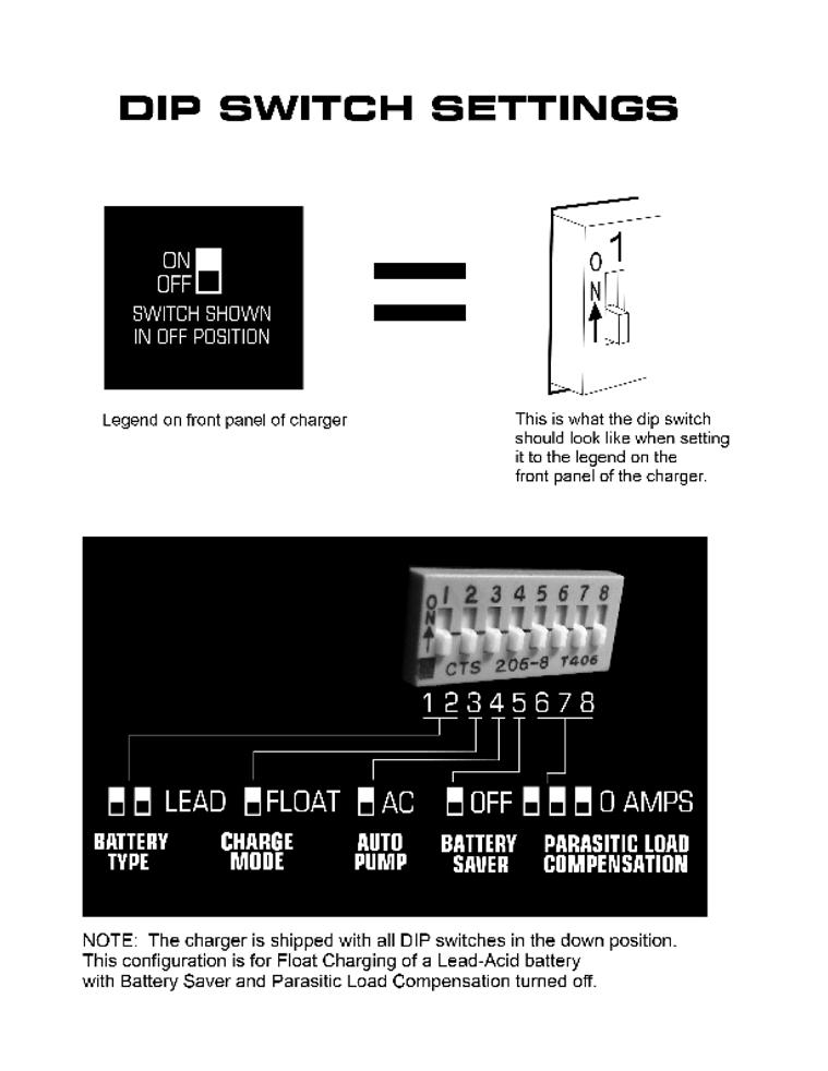
4 WIRING AND SWITCH SETTINGS I. BATTERY CHARGER WIRING INSTRUCTIONS 1. Refer to Installation Wiring Diagram I & II. 2. Refer to Wiring Specifications to determine the recommended wire size and maximum lengths.using a smaller gauge may cause overheating of the terminal. Additional information is available upon request if longer, larger wiring is required. 3. Torque DC output connector. Refer to Specifications. 4. Set the front panel switches for the appropriate battery type, charge method, safety timer value, battery saver mode and parasitic load requirement. Refer to Sections III, IV, V, VI and VII. 5. Double check all wiring and switch settings before applying AC power to input terminal. 6. Apply AC power (shoreline power) to input terminal and observe that the charger is operating. 7. Verify that the battery voltage appears at the charger output terminals. II. WIRING SPECIFICATIONS Length of Wire to Battery (feet) * 10-20* Battery Charger Connections III. BATTERY TYPE SELECTION SWITCHES Switches 1 and 2 should be set to match the battery chemistry. Lead-Acid - Both switches down (off) - factory default setting Gelled Electrolyte (Gel Cell) - Switch 1 down (off) and Switch 2 up (on) AGM - Switch 1 up (on) and Switch 2 down (off) Odyssey - Both switches up (on) IV. FLOAT / 3-STEP CHARGE MODE SELECTION SWITCHES PUMP + COM V. BAT + Switch 3 should be set for the desired charging method, Float or 3-Step. When in 3-step mode, the safety timer period is 3 hours. The safety timer period begins when AC power is applied to the charger. The absorption phase of 3-step charging terminates when the safety timer expires, or when the PLC threshold setting is reached. If no PLC settings are set, the threshold is 0.5A. The charger then switches to, and remains in, float mode while AC power is applied. Float Charge Only Switch 3 down (off) - factory default setting 3-Step with 3 Hour Safety Timer - Switch 3 up (on) B.S. + Wire # Gauge (awg) * Consult factory if length of wire to battery is longer than 20 feet PUMP + COM V. BAT + B.S. + PUMP + COM V. BAT + B.S. + 4
5 V. AUTO PUMP MODE SELECTION SWITCH Switch 4 controls the Auto Pump operating mode. AC Switch 4 down (off) - factory default setting. The compressor will operate only when AC power is applied to the battery charger. DC Switch 4 up (on). The compressor will operate when the AC power is on or off. It is powered by the charger while AC power is applied to the charger and from the vehicle s battery when no AC power is applied. VI. BATTERY SAVER SWITCH A low ripple, current limited, 3 ampere Battery Saver is built into the charger. When connected as shown in the installation wiring diagram, loads on the battery such as radios and rechargeable hand lights are automatically switched to the Battery Saver when power is applied to the charger. The Battery Saver allows more efficient charging by removing these loads from the battery. Switch 5 enables the Battery Saver when set in the up (on) position. If it is not required, turn the Battery Saver off by setting switch 5 down (off) position. This is the factory default setting. A Battery Saver filter is not required. WHEN A BATTERY SAVER OVERLOAD OCCURS: a. Remove the loads for approximately two minutes b. Reduce the load to 3 amperes or less c. Reapply the load to the Battery Saver No fuses are required or provided as the Battery Saver contains an automatic circuit breaker. VII. PARASITIC LOAD COMPENSATION SWITCHES (3-Step mode only) Switches 6, 7 and 8 should be set to match the parasitic load on the battery (excluding any Battery Saver load). These switches control the point at which the charger will terminate the absorption phase of the 3-step charging cycle. The possible settings are 0, 1, 2, 4, 6, 8, 10 or 12 amperes. If there are no parasitic loads on battery 1, or if they are all are on the Battery Saver, then set these three switches to the down (off) position. This is the factory default setting. VIII. REMOTE BATTERY CHARGE CONDITION INDICATOR (Standard equipment) This remote indicator shows the charge condition of each battery in 10 levels from LOW CHARGE to FULLY CHARGED. This device indicates a defective battery when the bar graph does not rise to the FULLY CHARGED level after an extended period of charging. NOTE: If the battery is being charged with an external load of 1.5 to 4 amperes across its terminals, the bar graph may move down 1 or 2 levels. This does not indicate a defective battery. To avoid this, connect all external loads to the Battery Saver terminals. Loads connected to the Battery Saver will be powered by the Battery Saver power supply when the AC power is ON, or they will be connected to the battery when the AC power is OFF. 5
6 6

7 INSTALLATION WIRING DIAGRAM I. FOR STANDARD BAR GRAPH DISPLAY, or OPTIONAL DELUXE STATUS CENTER, B-IND Wiring Diagram shown is for a 10 foot installation Remote Indicator NOTE: Pin 1 of indicator must go to Pin 1 of Remote Display on charger. Pin 2 of indicator must go to Pin 2 of Remote Display on charger, and so forth. Check connections and color of wires before plugging-in. Auto Pump Air Compressor 1 - RED 20AWG 2 - BLACK 20AWG 3 - WHITE 20AWG 4 - GREEN 20AWG INDICATOR PLC REMOTE 1 2 PUMP PLUS 1000 PLC ON OFF SWITCH SHOWN IN OFF POSITION PUMP LEAD FLOAT AC GEL 3-STEP DC AGM ODY BATTERY TYPE OUTPUT BAT1 CHARGE MODE BS AUTO PUMP FF 0N BATTERY SAVER 0 - AUTO 1 AMPS 2 AMPS 4 AMPS 6 AMPS 8 AMPS 10 AMPS 12 AMPS PARASITIC LOAD COMPENSATION SYSTEM POWER BLACK (14AWG) RED (14AWG) RED (14AWG) Chassis Ground BLACK (12AWG) RED (12AWG) 40 Amp fuse or Waterproof Circuit Breaker Kussmaul Part #: Install near the battery Volts BLK BLK RED RED Pressure Switch BATTERY BLACK (14AWG) BLACK (12AWG) RED (12AWG) 93.1 Battery Saver Loads (3 amps max.). When the charger is disconnected from 120 volts AC the Battery Saver loads automatically are connected to battery #1. Accessories WIRE SIZE CHART 7
8 II. FOR OPTIONAL WATERTIGHT DELUXE STATUS CENTER, B-IND-WT-XX Wiring Diagram shown is for a 10 foot installation 1 - RED 20AWG 2 - BLACK 20AWG 3 - WHITE 20AWG 4 - GREEN 20AWG NOTE: Pin 1 of indicator must go to Pin 1 of Remote Display on charger. Pin 2 of indicator must go to Pin 2 of Remote Display on charger, and so forth. Check connections and color of wires before plugging-in. Auto Pump Air Compressor Remote Indicator 1 - RED 20AWG 2 - BLACK 20AWG 3 - WHITE 20AWG 4 - GREEN 20AWG INDICATOR PLC REMOTE 1 2 PUMP PLUS 1000 PLC ON OFF SWITCH SHOWN IN OFF POSITION LEAD FLOAT AC GEL 3-STEP DC AGM ODY BATTERY TYPE OUTPUT PUMP BAT1 CHARGE MODE BS AUTO PUMP FF 0N BATTERY SAVER 0 - AUTO 1 AMPS 2 AMPS 4 AMPS 6 AMPS 8 AMPS 10 AMPS 12 AMPS PARASITIC LOAD COMPENSATION SYSTEM POWER BLACK (14AWG) RED (14AWG) RED (14AWG) Chassis Ground BLACK (12AWG) RED (12AWG) 40 Amp fuse or Waterproof Circuit Breaker Kussmaul Part #: Install near the battery Volts BLK BLK RED RED Pressure Switch BATTERY BLACK (14AWG) BLACK (12AWG) RED (12AWG) 93.1 Battery Saver Loads (3 amps max.). When the charger is disconnected from 120 volts AC the Battery Saver loads automatically are connected to battery #1. Accessories WIRE SIZE CHART 8
9 SPECIFICATIONS Input Power: 120 Volt, 60 Hz, 3.5 amperes Input Fuse: 6 ampere, fast blow Output Power - Bat : 15 amperes max (18 amperes if Battery Saver is turned off) Battery Type Float V DC Absorbtion V DC Lead-Acid Gelled Electrolyte AGM Odyssey Output Power - Battery Saver: 13 Volts DC, 3 amperes max Pump Output: 12 Amp Max Remote Sensing: Electronic, sense wires not required LED Status Indicators: Power: Green LED, Indicates 120 Volt AC power applied System: Yellow LED: Fast Flash (5 times per Second) indicates battery reverse polarity Slow Flash (once per second) indicates no battery is connected Solid On indicates charger is in current limit (normal operation) Solid Off indicates normal operation Brief Flash (once every 2 seconds) indicates 3-step boost mode operation Cooling Fan: The whisper quiet cooling fan exhausts air from the rear of the charger. When the Battery Saver is enabled, it is continuously on while AC power is applied to the charger. It turns on at 4 amperes of output current and turns off at 3 amperes when the Battery Saver is disabled. Torque: DC Output Connector: 15 in. lbs. Remote Display Options: Bar Graph Display, Deluxe Status Center or Watertight Status Center Output Waterproof Circuit Breaker (Optional): Bat 1-40 amperes, P/N: Output Buss Bar (Optional): 5 Studs, P/N: Weight: 11 pounds 9

10 OUTLINE DRAWING 10


11 OPTIONAL ACCESSORIES I. GRAPH DISPLAY, MODEL #: Segment LED display indicate the state of charge and the general condition of the batteries II. DELUXE STATUS CENTER, MODEL #: B-IND Indicator has a digital voltage and ampere display 5 segment bar graph display indicates output current 4 LED s to show the condition of the batteries III. WATERTIGHT DELUXE STATUS CENTER, MODEL #: B-IND-WT-XX Indicator has digital voltage and ampere display 5 segment bar graph display indicates output current 4 LED s to show the condition of the batteries Indicator is housed in a watertight bezel Bezel is available in 6 different colors, Red, White, Blue, Yellow, Gray, and Black Specify color choice when ordering IV. 40 AMP WATERPROOF CIRCUIT BREAKER, MODEL #: Combines switching and circuit breaker function Compact size and surface mount configuration Protects high amperage circuits Latch arms resets breaker after overload Cannot be held in ON position if short remains on circuit Waterproof - Ideal for truck applications 11
12 INSTALLATION RECORD DATE INSTALLED INSTALLED BY VEHICLE IDENTIFICATION VEHICLE OWNER WARRANTY POLICY All products of Kussmaul Electronics Company Inc. are warranted to be free of defects of material or workmanship. Liability is limited to repairing or replacing at our factory, without charge, any material or defects which become apparent in normal use within 3 years from the date the equipment was shipped. Equipment is to be returned, shipping charges prepaid and will be returned, after repair, shipping charges paid. Kussmaul Electronics Company, Inc. shall have no liability for damages of any kind to associated equipment arising from the installation and/or use of the Kussmaul Electronics Company, Inc. products. The purchaser, by the acceptance of the equipment, assumes all liability for any damages which may result from its installation, use or misuse, by the purchaser, his or its employees or others. 12
PUMP PLUS 2000 PLC MODEL #: PP AUTOMATIC DUAL OUTPUT BATTERY CHARGER INSTRUCTION MANUAL
 INSTRUCTION MANUAL PUMP PLUS 2000 PLC AUTOMATIC DUAL OUTPUT BATTERY CHARGER Supplied with Dual Bar Graph Display MODEL #: 091-237-12-PP INPUT: 120 Volt, 60 Hz, 3.5 Amps OUTPUT BATTERY 1 and 2: 15 or 18
LPC 40 MODEL #: LOW PROFILE CHARGER WITH PLC AUTOMATIC SINGLE OUTPUT BATTERY CHARGER INSTRUCTION MANUAL
 INSTRUCTION MANUAL LPC 40 LOW PROFILE CHARGER WITH PLC AUTOMATIC SINGLE OUTPUT BATTERY CHARGER Unit supplied with one of these displays MODEL #: 091-200-12 INPUT: 120 Volt, 50/60 Hz, 5 Amps OUTPUT: 40
AUTO CHARGE 4000 MODEL #: LOW PROFILE CHARGER AUTOMATIC DUAL OUTPUT BATTERY CHARGER INSTRUCTION MANUAL
 INSTRUCTION MANUAL AUTO CHARGE 4000 LOW PROFILE CHARGER AUTOMATIC DUAL OUTPUT BATTERY CHARGER Unit supplied with this display MODEL #: 091-89-12 INPUT: 120 Volt, 50/60 Hz, 5 Amps OUTPUT: 45 Amps File:
AUTO CHARGE 4000 MODEL #: AUTOMATIC DUAL OUTPUT BATTERY CHARGER INSTRUCTION MANUAL. Ph: Fax:
 INSTRUCTION MANUAL AUTO CHARGE 4000 AUTOMATIC DUAL OUTPUT BATTERY CHARGER MODEL #: 091-89-12 INPUT: 120 Volt, 50/60 Hz, 8 Amps OUTPUT BATTERY CHARGER: 40 Amps OUTPUT BATTERY SAVER: 5 Amps File: IM_091-89-12_reve.indd
LPC 20 MODEL #: LOW PROFILE CHARGER AUTOMATIC SINGLE OUTPUT BATTERY CHARGER INSTRUCTION MANUAL
 INSTRUCTION MANUAL LPC 20 LOW PROFILE CHARGER AUTOMATIC SINGLE OUTPUT BATTERY CHARGER Unit supplied with one of these displays MODEL #: 091-207-12 INPUT: 120 Volt, 50/60 Hz, 7 Amps OUTPUT: 20 Amps File:
AUTO CHARGE 12 HO MODEL #: MODEL #: MODEL #: AUTOMATIC SINGLE OUTPUT BATTERY CHARGER INSTRUCTION MANUAL
 INSTRUCTION MANUAL AUTO CHARGE 12 HO AUTOMATIC SINGLE OUTPUT BATTERY CHARGER MODEL #: 091-170-6 MODEL #: 091-170-12 MODEL #: 091-170-24 File: IM_091-170-xx_revd.indd Rev: D Revised By: MFG Date: 10-23-2013
AUTO CHARGE D2 MODEL #: AUTOMATIC TRIPLE OUTPUT BATTERY CHARGER INSTRUCTION MANUAL
 INSTRUCTION MANUAL AUTO CHARGE D2 AUTOMATIC TRIPLE OUTPUT BATTERY CHARGER Designed Specifically for Vehicles with DDEC ENGINES MODEL #: 091-74-12 INPUT: 120 Volt, 60 Hz, 8 Amps OUTPUT VEHICLE BATTERY 1
AUTO CHARGE D PUMP PLUS
 INSTRUCTION MANUAL AUTO CHARGE D PUMP PLUS AUTOMATIC DUAL OUTPUT BATTERY CHARGER Designed Specifically for Vehicles with DDEC ENGINES MODEL #: 091-9-DPP INPUT: 120 Volt, 60 Hz, 8 Amps OUTPUT VEHICLE BATTERY:
AUTO CHARGE DUAL MODEL #: AUTOMATIC DUAL OUTPUT BATTERY CHARGER INSTRUCTION MANUAL. Ph: Fax:
 INSTRUCTION MANUAL AUTO CHARGE DUAL AUTOMATIC DUAL OUTPUT BATTERY CHARGER MODEL #: 091-145-12 INPUT: 120 Volt, 50/60 Hz, 3.5 Amps OUTPUT BAT 1: 10 Amps OUTPUT BAT 2: 10 Amps File: IM_091-145-12_revb.indd
PUMP PLUS 1200 MODEL #: AUTOMATIC SINGLE OUTPUT BATTERY CHARGER INSTRUCTION MANUAL
 INSTRUCTION MANUAL UM LUS 1200 AUTOMATIC SINGLE OUTUT BATTERY CHARGER Unit supplied with one of these displays MODEL #: 091-193-12 INUT: 120 Volt, 60 Hz, 10 Amps OUTUT: 40 Amps File: IM_091-193-12_revH.indd
BATTERY SAVER LOW RIPPLE HO
 INSTRUCTION MANUAL BATTERY SAVER LOW RIPPLE HO LOW RIPPLE POWER SUPPLY / AUTOMATIC LOAD SWITCH FOR 12VDC VEHICLE SYSTEMS MODEL #: 091-195-12 INPUT: 120 Volt, 50/60 Hz, 4.5 Amps RMS OUTPUT: 13.2 Volts DC,
AUTO CHARGE 11 MODEL #: XX. AUTOMATIC BATTERY CHARGER U.L. Configuration INSTRUCTION MANUAL
 INSTRUCTION MANUAL AUTO CHARGE 11 AUTOMATIC BATTERY CHARGER U.L. Configuration MODEL #: 091-11-XX NOTE : This charger is designed for vehicles with dual batteries and negative ground. CAUTION This unit
AUTO CHARGE LPC SERIES
 INSTRUCTION MANUAL FILE: IM_091-206-12_revB REV: B REVISED BY: THN DATE: 09-17-2012 AUTO CHARGE LPC SERIES MODEL #091-206-12 LPC STANDARD DISPLAY INPUT: 115 volt, 50/60 Hz, 13 amps OUTPUT: 80 AMPERES 3
AUTO CHARGE 1200 PUMP PLUS
 FILE: 091-193-12.pmd REV: B REVISED BY: MFG DATE: 2-14-2011 INSTRUCTION MANUAL AUTO CHARGE 1200 PUMP PLUS AUTOMATIC BATTERY CHARGER MODEL #091-9-1200 INPUT: 115 volt, 50/60 Hz, 10 amps OUTPUT: 40 AMPERES
AUTO CHARGE 12 AUTOMATIC BATTERY CHARGER
 INSTRUCTION MANUAL FILE: 091-165-12 reve Rev: E, page 8 DATE: 7-02-15 AUTO CHARGE 12 AUTOMATIC BATTERY CHARGER MODEL #091-165-12 NOTE : This charger is designed for vehicles with a single battery and negative
INSTRUCTION MANUAL AUTO CHARGE MODEL # OUTPUT: 15 AMPERES 3 YEAR WARRANTY KUSSMAUL ELECTRONICS CO., INC.
 File: 091-56-12 rev b.pmd Rev: B, Date: 4-1-10 INSTRUCTION MANUAL AUTO CHARGE 1000 AUTOMATIC BATTERY CHARGER MODEL #091-56-12 INPUT :115 volt, 50/60 Hz, 3.5 amps OUTPUT: 15 AMPERES 3 YEAR WARRANTY KUSSMAUL
MODEL 6010A 6 12 VOLT BATTERY CHARGER ASSOCIATE
 MODEL 600A 6 VOLT BATTERY CHARGER ASSOCIATE IMPORTANT SAFETY INSTRUCTIONS. SAVE THESE INSTRUCTIONS. This manual contains important safety and operating instructions for the battery charger you have purchased.
INSTRUCTION MANUAL MODEL # NOTE : This charger is designed for vehicles with dual batteries and negative ground.
 INSTRUCTION MANUAL FILE: 091-9-2000.P65 DATE: 4-23-2000 REV. A AUTO CHARGE 2000 PUMP-PLUS AIR COMPRESSOR / BATTERY CHARGER MODEL #091-9-2000 NOTE : This charger is designed for vehicles with dual batteries
INSTRUCTION MANUAL REMOTE OUTPUT: 40 AMPERES 3 YEAR WARRANTY KUSSMAUL ELECTRONICS CO., INC.
 FILE: 091-53-12-REMOTE rev g.pmd REV: G 04-01-10 MFG INSTRUCTION MANUAL AUTO CHARGE 1200 REMOTE AUTOMATIC BATTERY CHARGER MODEL #091-53-12-REMOTE INPUT :115 volt, 50/60 Hz, 10 amps OUTPUT: 40 AMPERES 3
Installation and Operating Instructions (for chargers shown below)
") Installation and Operating Instructions (for chargers shown below) For additional information please call our Technical Support Group 800.742.2740 PRO CHARGING SYSTEMS, LLC 1551 Heil Quaker Boulevard,
Installation and Operating Instructions (for chargers shown below) For additional information please call our Technical Support Group 800.742.2740 PRO CHARGING SYSTEMS, LLC 1551 Heil Quaker Boulevard,
OPERATOR'S MANUAL IMPORTANT SAFETY INSTRUCTIONS
 ASSOCIATED OPERATOR'S MANUAL IMPORTANT SAFETY INSTRUCTIONS MODEL 6366 12 VOLT, 0-20 AMP 4 X 20 BATTERY CHARGER 1. SAVE THESE INSTRUCTIONS. This manual contains important safety and operating instructions
INTELLIGENT BATTERY CHARGER/MAINTAINER
 INTELLIGENT BATTERY CHARGER/MAINTAINER OWNER S MANUAL Read carefully and understand all ASSEMBLY AND OPERATION INSTRUCTIONS before operating. Failure to follow the safety rules and other basic safety precautions
Safety, Installation And Operating Instructions For The Following Battery Charger Models: i2412, i3612, i4809, i2425, i3625, and i4818
 Safety, Installation And Operating Instructions For The Following Battery Charger Models: i2412, i3612, i4809, i2425, i3625, and i4818 IMPORTANT NOTICE: Please save and read these safety, operating and
OWNER S MANUAL. Model YUA2AMPCH 2 AMP Dual-Bank Automatic Battery Charger & Maintainer READ ENTIRE MANUAL BEFORE USING THIS PRODUCT
 Model YUA2AMPCH 2 AMP Dual-Bank Automatic Battery Charger & Maintainer Certified by California BCS Regulations OWNER S MANUAL READ ENTIRE MANUAL BEFORE USING THIS PRODUCT READ ENTIRE MANUAL BEFORE USING
LESTRONIC II BATTERY CHARGER MODEL 07210
 LESTRONIC II BATTERY CHARGER MODEL 07210 PLEASE SAVE THESE IMPORTANT SAFETY AND OPERATING INSTRUCTIONS For correct operation of the equipment, it is important to read and be familiar with this entire manual
10 AMP ON BOARD BATTERY CHARGER
 R A Valley Forge Company MODEL 2611A-1-B 10 AMP ON BOARD BATTERY CHARGER One Output OWNER S MANUAL IMPORTANT! READ THESE INSTRUCTIONS BEFORE INSTALLING AND USING THIS PRODUCT. Keep these instructions for
INSTRUCTION MANUAL CAUTION
 FILE: IM_091-128-12E-40-115 Rev B., 2-16-2006 INSTRUCTION MANUAL AUTO CHARGE ODY q AUTOMATIC BATTERY CHARGER MODEL #091-128-12E-40-115 for ODYSSEY AGM BATTERIES CAUTION This charger is calibrated to the
CRS1, CRS2 and CRS3. For additional information please call our. PRO CHARGING SYSTEMS, LLC 1551 Heil Quaker Boulevard, LaVergne, TN
 CRS1, CRS2 and CRS3 For additional information please call our Technical Support Group 800.742.2740 PRO CHARGING SYSTEMS, LLC 1551 Heil Quaker Boulevard, LaVergne, TN 37086-3539 110310 Installation and
12V 1 AMP (1000 ma) Automatic Battery Charger & Maintainer
 Automatic Battery Charger & Maintainer") 12V 1 AMP (1000 ma) Automatic Battery Charger & Maintainer For lead-acid batteries THIS MANUAL CONTAINS IMPORTANT SAFETY AND OPERATING INSTRUCTIONS FOR 12V BATTERY CHARGER: YUA1201000 / INT1201000 KEEP
12V 1 AMP (1000 ma) Automatic Battery Charger & Maintainer For lead-acid batteries THIS MANUAL CONTAINS IMPORTANT SAFETY AND OPERATING INSTRUCTIONS FOR 12V BATTERY CHARGER: YUA1201000 / INT1201000 KEEP
MODEL 6017 OPERATOR'S MANUAL
 MODEL 6017 OPERATOR'S MANUAL ASSOCIATE D IMPORTANT SAFETY INSTRUCTIONS 1. SAVE THESE INSTRUCTIONS. This manual contains important safety and operating instructions for the battery charger you have purchased.
INSTRUCTION MANUAL. 12-Station HD Shop 12V Portable Battery Charger
 INSTRUCTION MANUAL 12-Station HD Shop 12V Portable Battery Charger IMPORTANT SAFETY INSTRUCTIONS 1. SAVE THESE INSTRUCTIONS This manual contains important safety and operating instructions for your HD
installation and operating instructions for the following xtreme Battery chargers:
 installation and operating instructions for the following xtreme Battery chargers: Model Name No. of Banks Amps Per Bank Battery System Dual Pro SE Xtreme Dual Pro Xtreme Three Bank SE Xtreme Three Bank
SP6. Automatic Battery Charger. Model
 Model SP6 Automatic Battery Charger OWNERS MANUAL PLEASE SAVE THIS OWNERS MANUAL AND READ BEFORE EACH USE. This manual will explain how to use the charger safely and effectively. Please read and follow
IMPORTANT SAFETY INSTRUCTIONS
 1163714 1.5 AMP 12VOLT TRICKLE 1.5 AUTOMATIC AMP AUTOMATIC TRICKLE 1.5 AMP AUTOMATIC 12V12VOLT BATTERY CHARGER IMPORTANT SAFETY INSTRUCTIONS 1. SAVE THESE INSTRUCTIONS This product offers a wide range
801 BUSINESS CENTER DRIVE MOUNT PROSPECT, ILLINOIS
 280-600 Send Warranty Product Repairs to: 1025 E. Thompson Ave., Hoopeston, IL 60942-0280. Call Customer Service if you have questions: 1-800-621-5485 A. IMPORTANT SAFETY INSTRUCTIONS 1. SAVE THESE INSTRUCTIONS
AC CONVERTER / BATTERY CHARGER
 AC CONVERTER / BATTERY CHARGER User s Manual MODEL #: CON120AC12/24VDC Listed to UL 458 and CSA 22.2 NO. 107.1 Standards Contents INTRODUCTION... 3 Important Safety Instructions... 3 1. General Description...
801 BUSINESS CENTER DRIVE MOUNT PROSPECT, ILLINOIS Ext. 322
 277-999 ELECTRIC CORP. 801 BUSINESS CENTER DRIVE MOUNT PROSPECT, ILLINOIS 800-621-5485 Ext. 322 Send Warranty Product Repairs to: 605 South Vermilion, Suite C, Brownsville, TX 78521-6851 Call Customer
Cruising Charger Series OWNER S MANUAL
 R Cruising Charger Series OWNER S MANUAL ON BOARD BATTERY CHARGERS Models DC Amperage No. Of Banks Volts 2614A 5,10 Amps 2 Bank 12/12 2614A-230 2621A 5,5,10 Amps 3 Banks 12/12/12 2621A-230 2622A 10,10
Models: SP3, SPSS3 Automatic Battery Charger
 OWNERS MANUAL Models: SP3, SPSS3 Automatic Battery Charger PLEASE SAVE THIS OWNERS MANUAL AND READ BEFORE EACH USE. This manual will explain how to use the charger safely and effectively. Please read and
IMPORTANT SAFETY INSTRUCTIONS IMPORTANT: READ AND SAVE THIS SAFETY AND INSTRUCTION MANUAL. KEEP IT WITH OR NEAR CHARGER AT ALL TIMES.
 IMPORTANT SAFETY INSTRUCTIONS IMPORTANT: READ AND SAVE THIS SAFETY AND INSTRUCTION MANUAL. KEEP IT WITH OR NEAR CHARGER AT ALL TIMES. SPECIFICATIONS: For technical assistance, call your Dealer with the
BATTERY CHARGER CHR-1445
 BATTERY CHARGER CHR-1445 / 2685 TEL:886-4-2238-0698 FAX:886-4-2238-0891 Web Site:http://www.monicon.com.tw E-mail:sales@monicon.com.tw Copyright 2007 Monicon Instruments Co., Ltd. All right reserved. Contents
LESTRONIC II BATTERY CHARGER BUILT-IN OR PORTABLE CHARGERS
 LESTRONIC II BATTERY CHARGER BUILT-IN OR PORTABLE CHARGERS PLEASE SAVE THESE IMPORTANT SAFETY AND OPERATING INSTRUCTIONS For correct operation of the equipment, it is important to read and be familiar
2603 Battery Pal 3 AMP, 1 2 VOLT BATTERY CHARGER
 R 2603 Battery Pal 3 AMP, 1 2 VOLT BATTERY CHARGER Connections at a glance: The GUEST Battery Pal 2603 is designed to recharge your battery, and extend your battery s life in applications where it is stored
AUTO CHARGE 3 STEP AUTOMATIC BATTERY CHARGER
 INSTRUCTION MANUAL FILE: IM_091-120-XX-XX-(XXX)(XX)_revA.P65 REV: A REVISED BY: PSS DATE: 07-19-13 AUTO CHARGE 3 STEP AUTOMATIC BATTERY CHARGER R MODEL #091-120-XX-XX-(XXX)(XX) 3 YEAR WARRANTY 170 Cherry
LESTRONIC II BATTERY CHARGER MODEL 19740
 *01679* LESTRONIC II BATTERY CHARGER MODEL 19740 PLEASE SAVE THESE IMPORTANT SAFETY AND OPERATING INSTRUCTIONS For correct operation of the equipment, it is important to read and be familiar with this
AUTO CHARGE 11HO PIM AUTOMATIC BATTERY CHARGER
 BOOK# 091-11HO-PIM-1 INSTRUCTION MANUAL AUTO CHARGE 11HO PIM AUTOMATIC CHARGER MODEL #091-11HO-PIM NOTE : This charger is designed for vehicles with dual batteries and negative ground. INPUT :115 volts,
DUAL 12 Volt-10 Amp AUTOMATIC BATTERY CHARGER
 FILE: 091-145 DATE: 01-02-02 INSTRUCTION MANUAL DUAL 12 Volt-10 Amp AUTOMATIC BATTERY CHARGER MODEL #091-145 INPUT: 120 Volts, 50/60 Hz AC OUTPUT 1: 12 Volts, DC, Isolated OUTPUT 2: 12 Volts, DC, Isolated
Installation and Operating Instructions (for chargers shown below)
") Installation and Operating Instructions (for chargers shown below) For additional information please call our Technical Support Group 800.742.2740 PRO CHARGING SYSTEMS, LLC 1551 Heil Quaker Boulevard,
Installation and Operating Instructions (for chargers shown below) For additional information please call our Technical Support Group 800.742.2740 PRO CHARGING SYSTEMS, LLC 1551 Heil Quaker Boulevard,
MODEL 2602A-12 3 STAGE AUTOMATIC BATTERY CHARGER OWNER S MANUAL SAVE THESE INSTRUCTIONS
 R A Valley Forge Company MODEL 2602A-12 3 STAGE AUTOMATIC BATTERY CHARGER OWNER S MANUAL SAVE THESE INSTRUCTIONS 1. INTRODUCING THE CHARGER The 2602A-12 is a 3-stage electronic battery charger. Rainproof,
MODEL A96 SERIES. 130Vdc Switchmode Utility Rectifier / Battery Charger. Used with LaMarche Power Cage ECN/DATE
 MODEL A96 SERIES 130Vdc Switchmode Utility Rectifier / Battery Charger Used with LaMarche Power Cage CPN112138 ECN/DATE ISSUE DATE: ECN 17010-12/05 106 BRADROCK DRIVE DES PLAINES, IL. 60018-1967 (847)
10AMP FULLY AUTOMATIC 6V & 12V BATTERY CHARGER OWNER'S MANUAL
 1244502 10AMP FULLY AUTOMATIC 6V & 12V BATTERY CHARGER OWNER'S MANUAL 1. IMPORTANT SAFETY INSTRUCTIONS 1.1 SAVE THESE INSTRUCTIONS This manual contains important safety and operating instructions. 1.2
24 VOLT AUTOMATIC BATTERY CHARGER PART NO
 24 VOLT AUTOMATIC BATTERY CHARGER PART NO. 957732 AC Input: DC Output: Battery Type: Specifications 230 volts, 50 hertz, 3.5 amps, single-phase 24 volts, 20 amps initially tapering to 6 amps 24 volt, 12
2/10/50 AMP 12 VOLT BATTERY CHARGER/ ENGINE STARTER
 2/10/50 AMP 12 VOLT BATTERY CHARGER/ ENGINE STARTER WARNING This product contains or, when used, produces a chemical known to the State of California to cause cancer and birth defects or other reproductive
Installation and Operating Instructions (for chargers shown below)
") Installation and Operating Instructions (for chargers shown below) For additional information please call our Technical Support Group 800.742.2740 PRO CHARGING SYSTEMS, LLC 1551 Heil Quaker Boulevard,
Installation and Operating Instructions (for chargers shown below) For additional information please call our Technical Support Group 800.742.2740 PRO CHARGING SYSTEMS, LLC 1551 Heil Quaker Boulevard,
Model: OBD-L On-Board-Diagnostics II Memory Saver Detector
 Model: OBD-L On-Board-Diagnostics II Memory Saver Detector OWNERS MANUAL IMPORTANT SAFETY INSTRUCTIONS SAVE THESE INSTRUCTIONS This manual will show you how to use your memory saver detector safely and
Deltran Battery Tender 6V/12V 4Amp 5 & 10 Bank Battery Management System TABLE 1. Length of Cord, Feet AWG Size of Cord
 Deltran Battery Tender 6V/12V 4Amp 5 & 10 Bank Battery Management System Designed for Six-cell and three-cell Flooded/AGM/GEL Lead-Acid Batteries and Four-Cell Lithium Iron Phosphate (LiFePO4) Batteries
12V/25A BATTERY CHARGER MAINTAINER / JUMPSTARTER
 12V/25A BATTERY CHARGER MAINTAINER / JUMPSTARTER OWNER S MANUAL Read carefully and understand all ASSEMBLY AND OPERATION INSTRUCTIONS before operating. Failure to follow the safety rules and other basic
Model: SE-4020-CA Automatic Battery Charger
 OWNERS MANUAL Model: SE-4020-CA Automatic Battery Charger PLEASE SAVE THIS OWNERS MANUAL AND READ BEFORE EACH USE. This manual will explain how to use the battery charger safely and effectively. Please
ACCUSENSE CHARGE SERIES ON/OFF BOARD FULLY AUTOMATIC BATTERY CHARGER
 ACCUSENSE CHARGE SERIES ON/OFF BOARD FULLY AUTOMATIC BATTERY CHARGER SPECIFICATIONS: *Photo for reference only* Part number 8890439 Mode Select: Selects Battery Type Refer to Section 6. IMPORTANT: READ
BatteryMINDer 1500* & BatteryMINDer Plus 1510*
 BatteryMINDer 1500* & BatteryMINDer Plus 1510* both with SmarTECHnology 12 Volt 1500 ma Charger - Maintainer - Desulfator INCLUDES: Auto-Temp Compensation Sensor, installed (1500 & 1510) Optional Permanent
Operating Instructions
 Operating Instructions PRO- If you sell, inventory or service lead-acid batteries, you want the battery you take off the shelf to be as new as the day it was manufactured. However, batteries that sit idle
Digital Mobile Charge Advanced Electronic In-Transit 4-Stage Battery to Battery Charger
 Digital Mobile Charge Advanced Electronic In-Transit 4-Stage Battery to Battery Charger Owner s Manual and Installation Guide Model Part Number Description Digital Mobile Charge 05502 Advanced In-Transit
Sentry Battery Charger. Installation and Operations Manual Section 75
 Sentry Battery Charger Installation and Operations Manual 00-02-0616 03-03-08 Section 75 In order to consistently bring you the highest quality, full featured products, we reserve the right to change our
MODEL A97 SERIES. Switchmode Utility Rectifier/Battery Charger ECN/DATE
 MODEL A97 SERIES Switchmode Utility Rectifier/Battery Charger CPN108172 ISSUE DATE: 16071 7/03 ECN/DATE 106 BRADROCK DRIVE DES PLAINES, IL. 60018-1967 (847) 299-1188 FAX: (847)299-3061 Page 1 of 7 INSTRUCTION
SAVE THESE INSTRUCTIONS
 R MODEL 2611 10 AMP ON BOARD BATTERY CHARGER Two Outputs OWNER S MANUAL Connections at a glance: For the best charging results both 12 Volt independent batteries should be equally discharged. The charger
Art. No. EC-315. Art. No. EC-330. Art. No. EC-340 SWITCH-MODE BATTTERY CHARGER CONTENTS IMPORTANT SAFETY PRECAUTIONS... 2
 SWITCH-MODE BATTTERY CHARGER CONTENTS IMPORTANT SAFETY PRECAUTIONS... 2 DESCRIPTION AND FEATURES... 3 CHARGING STAGES... 4 Art. No. EC-315 Art. No. EC-330 Art. No. EC-340 PROTECTIONS... 5 INSTALLATION...
Intelligent Charging System Series
 R Intelligent Charging System Series OWNER S MANUAL ON BOARD BATTERY CHARGERS Models Amperage No. Of Banks Volts 16061 s 1 Bank 12 16102 6,s 2 Banks 12 or 24 16153 6,6,s 3 Banks 12 or 24 or 36 16202 10,10
12 Volt 1500 ma Convertible Charger - Maintainer - Desulfator*
 1215C 12 Volt 1500 ma Convertible Charger - Maintainer - Desulfator* INCLUDES: Auto-Temp Compensation Sensor, installed Optional Permanent Mounting Brackets and screws Battery Clips (Fully-Insulated 6
AUTO CHARGE 12HO-PIM AUTOMATIC BATTERY CHARGER
 BOOK# 091-12HO-1 INSTRUCTION MANUAL AUTO CHARGE 12HO-PIM AUTOMATIC BATTERY CHARGER MODEL #091-12HO-PIM NOTE : This charger is designed for vehicles with a single battery system INPUT :115 volt, 50/60 Hz,
BATTERY CHARGER OWNER S MANUAL POWER CHARGER Part # volt Amp
 BATTERY CHARGER OWNER S MANUAL POWER CHARGER Part # 74016 12-16 volt Amp ----CAUTION---- READ THIS MANUAL CAREFULLY FOR RULES OF SAFE OPERATION AND PROPER USE OF THIS CHARGER ***SAVE THESE INSTRUCTIONS***
INDUSTRIAL CHARGER AUTOMATIC BATTERY CHARGER SERIES 150 KUSSMAUL ELECTRONICS CO., INC. MODEL # XX YEAR WARRANTY INSTRUCTION MANUAL
 INSTRUCTION MANUAL FILE: 091-106-150-XX-120 DATE: 10-2-2009 REV: A INDUSTRIAL CHARGER AUTOMATIC BATTERY CHARGER SERIES 150 MODEL # 091-106-150-XX-120 3 YEAR WARRANTY KUSSMAUL ELECTRONICS CO., INC. 170
OPERATOR S MANUAL JUMP STARTER. and DC Power Source. Model No CAUTION: Sears, Roebuck and Co., Hoffman Estates, IL U.S.A.
 OPERATOR S MANUAL JUMP STARTER and DC Power Source Model No. 71489 CAUTION: Read and follow all Safety Rules and Operating Instructions before Every Use of this Product. SAVE THESE INSTRUCTIONS. Sears,
AUTOMATIC BEST BATTERY SELECTOR INSTALLATION & OPERATION BBS-1600 BBS-1600E
 AUTOMATIC BEST BATTERY SELECTOR INSTALLATION & OPERATION BBS-1600 BBS-1600E SENS part no: 101314 Document revision: H DCN No. 107395 Date 11/22/17 1840 Industrial Circle Longmont, CO 80501 Fax: (303) 678-7504
36 VOLT AUTOMATIC BATTERY CHARGER PART NO
 36 VOLT AUTOMATIC BATTERY CHARGER PART NO. 957727 AC Supply: DC Output: Battery Type: Specifications 120 volts, 60 Hertz, 10 amps, single-phase 36 volts, 20 amps initially tapering to 6 amps 36 volt, 18
A39 UNIVERSAL SCR CHARGER
 A39 UNIVERSAL SCR CHARGER ECN/DATE CPN35971 21681 01/18 16816-6/05 15349-03 05/02 14575 02/01 14268 10/00 10400 9/96 106 BRADROCK DRIVE DES PLAINES, IL. 60018-1967 (847) 299-1188 FAX: (847) 299-3061 ISSUE
Guardian Battery Charger Series. Installation and Operations Manual Section 75
 Guardian Battery Charger Series Installation and Operations Manual 00-02-0615 02-29-08 Section 75 In order to consistently bring you the highest quality, full featured products, we reserve the right to
AUTO ISOLATOR I AN AUTOMATIC LOSSLESS BATTERY ISOLATOR FOR DUAL BATTERY SYSTEMS
 INSTRUCTION MANUAL AUTO ISOLATOR I AN AUTOMATIC LOSSLESS ISOLATOR FOR DUAL SYSTEMS MODEL #: 091-139-2-12 VOLTAGE: 12 VDC OUTPUT: 12 VOLTS, 3 AMPS PARALLELING : 200 AMPS File: IM-091-139-2-12 Rev: revc
PSJ-2212, PSJ-3612, PSJ-4424
 Model: PSJ-2212, PSJ-3612, PSJ-4424 Jump Starter and DC Power Source OWNER S MANUAL PSJ-2212 PLEASE SAVE THIS OWNER S MANUAL AND READ BEFORE EACH USE. This manual will explain how to use your jump starter
A48 / A48B (base plate) BATTERY CHARGER
 BATTERY CHARGER") A48 / A48B (base plate) BATTERY CHARGER CPN41054 ISSUE DATE: 12315-8/98 ECN/DATE 106 BRADROCK DRIVE DES PLAINES, IL. 60018-1967 (847) 299-1188 FAX: (847)299-3061 15349-07-07/02 16041 6/03 14575-2/01 INSTRUCTION
A48 / A48B (base plate) BATTERY CHARGER CPN41054 ISSUE DATE: 12315-8/98 ECN/DATE 106 BRADROCK DRIVE DES PLAINES, IL. 60018-1967 (847) 299-1188 FAX: (847)299-3061 15349-07-07/02 16041 6/03 14575-2/01 INSTRUCTION
ELECTRONIC MARINE CONVERTER/CHARGER Owners Manual Models PD2020, PD2030, PD2040, PD2050, PD2060, PD2080
 Table Of Contents ELECTRONIC MARINE CONVERTER/CHARGER Owners Manual Models PD2020, PD2030, PD2040, PD2050, PD2060, PD2080 Thank you for purchasing the INTELI-POWER MARINE converter/charger. The INTELI-POWER
24V HEAVY DUTY JUMP STARTER/ POWER BANK MB3752. Storage. Specifications
 Storage Warning! When not in use store your instruction manual and product in a safe and dry place. Before re-use after storage it is recommended that the product is checked by a suitably qualified person
Battery. Charger Model: Save Important Safety Instructions
 Owner's Manual Battery Charger Model: SS-51A-PE, 10 Amp Fully Automatic Battery Charger For 12 Volt Marine Deep Cycle & Automotive Batteries Save Important Safety Instructions Read Rules for Safe Operation
12V Manual Battery Charger
 OPERATOR S MANUAL 12V Manual Battery Charger Model No. 28.71221 Read and follow all Safety Rules and Operating Instructions before Every Use of this Product. SAVE THESE INSTRUCTIONS. Sears Brands Management
GSL Electronics Modified Sine Wave Power Inverters
 GSL Electronics Modified Sine Wave Power Inverters Congratulations on choosing one of our Modified Sine Wave Inverters for your application. There are 6 models in the range, which will meet most of your
High Frequency SMT Golf Car Chargers Battery Tender Battery Charger Models: 12 Volt 20 Amp, 24 Volt 20 Amp, 36 Volt 15 Amp, 48 Volt 10 Amp
 Deltona Transformer Corporation High Frequency SMT Golf Car Chargers Battery Tender Battery Charger Models: 12 Volt 20 Amp, 24 Volt 20 Amp, 36 Volt 15 Amp, 48 Volt 10 Amp IMPORTANT SAFETY INSTRUCTIONS
Turbo M Series onboard charger
 Turbo M Series onboard charger Operation Manual Model # Output Bank Max. Output Turbo M106 1 6 Amps Turbo M108 1 8 Amps Turbo M208 2 8 Amps Turbo M212 2 12 Amps Turbo M220 2 20 Amps Turbo M230 2 30 Amps
OWNERS MANUAL Models: XP400, XP500, XP750C INSTANT POWER Jump Starter and DC Power Source
 OWNERS MANUAL Models: XP400, XP500, XP750C INSTANT POWER Jump Starter and DC Power Source XP400 XP500 XP750C PLEASE SAVE THIS OWNER S MANUAL AND READ BEFORE EACH USE. This manual will explain how to use
INSTRUCTION MANUAL. A battery protector for vehicles with equipment that Is operated with the engine not running. MODEL# INPUT: 12 Volts D.C.
 INSTRUCTION MANUAL FILE: IM_091-141_Rev_B DATE: 10-02-03 LOAD MANAGER P A battery protector for vehicles with equipment that Is operated with the engine not running MODEL# 091-141 INPUT: 12 Volts D.C.
CX-SERIES ADVANCED BATTERY CHARGER
 CX-SERIES ADVANCED BATTERY CHARGER Table of Content 1. IMPORTANT SAFETY INFORMATION... 2 1-1 General Safety Precautions... 2 1-2 Battery Precautions... 2 2. FEATURES... 3 2-1 Battery Charging Curve...
AUTOMATIC BEST BATTERY SELECTOR INSTALLATION & OPERATION BBS-4800 BBS-4800E
 AUTOMATIC BEST BATTERY SELECTOR INSTALLATION & OPERATION BBS-4800 BBS-4800E SENS part no: 101312 Document revision: K DCN No. 107455 Date 4/2/18 1840 Industrial Circle Longmont, CO 80501 Fax: (303) 678-7504
Go Power! Manual. GP-Smart Charger
 Go Power! Manual GP-Smart Charger Go Power! Electric Inc. PO Box 6033 Victoria, BC V8P 5L4 Toll Free Tel: 866-247-6527 Toll Free Fax: 866-607-6527 Email: info@gpelectric.com Table of Contents 1. IMPORTANT
DieHard. BATTERY CHARGER/MAINTAINER 1.5 Amp Fully Automatic Float-Mode Monitoring. Model No
 OWNER'S MANUAL DieHard. BATTERY CHARGER/MAINTAINER 1.5 Amp Fully Automatic Float-Mode Monitoring Model No. 200.71220 CAUTION: Read and follow all Safety Rules and Operating Instructions Before Every Use
Automatic Battery Charger Switching mode with Micro-controlled Input: Vac / Output: 12Volt DC
 Automatic Battery Charger Switching mode with Micro-controlled Input:220-260Vac / Output: 12Volt DC User s Manual and Important Safety Information Model: OC-SW121080 / OC-SW121160 / OC-SW121210 FEATURES
Automatic Battery Charger Switching mode with Micro-controlled Input: Vac / Output: 12Volt DC
 Automatic Battery Charger Switching mode with Micro-controlled Input:220-260Vac / Output: 12Volt DC User s Manual and Important Safety Information Model: OC-SW121080 / OC-SW121160 / OC-SW121210 FEATURES
General Precautions. Personnel Precautions
 USER MANUAL General Precautions 1. Before using Inverex, read all instructions and cautionary markings on : (1) Inverex (2) the batteries (3) this manual 2. CAUTION --To reduce risk of injury, charge only
Battery Enclosure Installation Instructions
 MNBE-C Battery Enclosure Instructions Battery Enclosure Installation Instructions MNBE-C These instructions are for the installation of Midnite Solar Battery Enclosure models MNBE-C, MNBE-CL16 and MNBE-C8D
12 VOLT 30 AMP DIGITAL SOLAR CHARGE CONTROLLER
 12 VOLT 30 AMP DIGITAL SOLAR CHARGE CONTROLLER User s Manual Congratulations on your Coleman solar product purchase. This product is designed to the highest technical specifications and standards. It will
Manual. EN Appendix. Blue Smart IP65 Charger 120V 12/7 12/10 12/15 24/8
 Manual EN Appendix Blue Smart IP65 Charger 120V 12/7 12/10 12/15 24/8 IMPORTANT SAFETY INSTRUCTIONS 1. SAVE THESE INSTRUCTIONS This manual contains important safety and operating instructions for Blue
BATTERY SAVER LR HO with USB LOW RIPPLE POWER SUPPLY / AUTOMATIC LOAD SWITCH FOR 12VDC VEHICLE SYSTEMS
 FILE: IM_091-195-12-USB_revB1 REVISED BY: PSS DATE: 06-28-2013 INSTRUCTION MANUAL BATTERY SAVER LR HO with USB LOW RIPPLE POWER SUPPLY / AUTOMATIC LOAD SWITCH FOR 12VDC VEHICLE SYSTEMS MODEL #091-195-12-USB
MB V 3-IN-1 JUMP STARTER WITH SPIRAL WOUND BATTERY
 MB3730 12V 3-IN-1 JUMP STARTER WITH SPIRAL WOUND BATTERY 1 IMPORTANT SAFETY INSTRUCTIONS 1. SAVE THESE INSTRUCTIONS - This manual contains important safety and operating instructions for this PowerStation.