HI-TRAC 100 HIGH SPEED WEIGH-IN-MOTION DATA COLLECTION & PRE-SELECTION SYSTEM UTILISING HI-COMM 100 SOFTWARE. System Overview
|
|
|
- Scott Johns
- 6 years ago
- Views:
Transcription

1934 644299 Fax : +44 (0)1934 644255 Email : sales@tdcsystems.co.uk Web : www.")
1 HI-TRAC 100 HIGH SPEED WEIGH-IN-MOTION DATA COLLECTION & PRE-SELECTION SYSTEM UTILISING HI-COMM 100 SOFTWARE System Overview HI-TRAC is a registered Trade Mark of TDC Systems Limited TDC Systems Limited Weston-Super-Mare ENGLAND Tel : +44 (0) Fax : +44 (0) sales@tdcsystems.co.uk Web :
2 TDC Systems Ltd HI-TRAC 100 Overview CONTENTS 1 System Overview 1.1 Introduction 1.2 Remote Site Configuration 1.3 Operating Principles 1.4 HI-TRAC 100 Electronic Unit 1.5 System Calibration 1.6 Maintenance 1.7 WIM Pre-Selection Operation 1.8 HI-TRAC 100 Front Panel Display 1.9 HI-TRAC 100 Menu 2 Performance and Accuracy Criteria 2.1 Road Sensor Configurations 2.2 Piezo-Loop-Piezo 2.3 Loop-Piezo-Loop 2.4 The Piezo Sensor 2.5 Bicycle Sensors 2.6 Why Use Piezoelectric Sensors 2.7 Comparison Table for Different Types of WIM Sensors 3 HI-TRAC 100 Data Storage Capacity 3.1 Vehicle by Vehicle Data Storage 3.2 Statistical Data Files 3.3 ATMS Data Files 3.4 Malfunction Management Files 4 HI-COMM 100 Software Package (Example Reports & Screen Displays) 5 Drawings..2..
3 TDC Systems Ltd HI-TRAC 100 Overview 1. HI-TRAC 100 SYSTEM OVERVIEW 1.1 Introduction The HI-TRAC 100 is a medium or high speed traffic classification and weigh-inmotion (WIM) system. The HI-TRAC 100 system provides a low-cost means of recording traffic data without interruption to traffic flow. The HI-TRAC 100 will detect and record traffic at speeds from 5 to at least 180 kph. The system consists of road-installed items of two piezo-electric sensors and an inductive loop per traffic lane. The HI-TRAC 100 electronic unit is installed in a protective roadside cabinet and connects to the road installed items. The signal from the piezo-electric sensors is monitored by the HI-TRAC 100 and used to calculate the axle loading, vehicle speed and vehicle inter-axle separation as the vehicle passes over the road sensor array. The HI-TRAC 100 electronic unit monitors the inductive loop signal to determine vehicle presence time over the road sensor array and hence provides an indication of the lane occupancy. The inductive loop signal is also used by HI-TRAC to determine vehicle chassis length and as an end-of-vehicle detector to separate closely passing traffic. A 4-line by 20-character LCD located on the front panel displays the data recorded from the last vehicle and in conjunction with a 16-key membrane keypad facilitates localised setting of configuration parameters, calibration and other functions. The system may be linked via a modem and telephone line, a GSM modem or a data (RS485) cable link to a PC for downloading of data, administration and real time viewing of traffic. Additionally a laptop computer can be connected locally via a serial (RS232) port on the front panel of the HI-TRAC 100. Data is stored internally on an SRAM memory card. The HI-TRAC 100 is installed as standard with a 4Mbyte card, which will store up to 400,000 vehicle records when operating in the WIM mode. An upgrade to either a 6Mbyte or 8Mbyte memory card is available. The HI-TRAC 100 electronic unit is housed in a weatherproof cabinet installed at the roadside. Power can be supplied by various means; continuous monitoring requires either AC mains or a solar panel/battery set-up, whereas temporary installations can be supplied by a battery of suitable size (dependant upon length of survey). A backup battery is normally recommended if the system is powered via AC mains. The HI-TRAC 100 system utilizes the TDC Systems Neural Network Temperature Compensation Algorithm to continually fine tune temperature compensation for optimum system performance and accuracy. The standard HI-TRAC 100 system connects to 4 lanes of road-installed sensors but it is upgradeable to connect to a maximum of 8 lanes...3..
4 TDC Systems Ltd HI-TRAC 100 Overview 1.2 Remote Site Configuration The HI-TRAC 100 electronic unit is capable of interfacing to sixteen piezo-electric sensors and eight inductive loops. In the standard configuration of two piezo-electric sensors and one inductive loop, per lane of traffic measuring, this provides a maximum of 8 lanes of data recording. For a weigh-in-motion (WIM system) installation of Class 1 piezo-electric sensors are preferred. For an installation that is required to only count and classify vehicles (an AVC system) Class 2 piezo-electric sensors provide a more cost-effective solution. With a WIM installation it is necessary to install an in-road thermistor to provide road temperature information to the HI-TRAC 100 system. This is used for temperature correction of the recorded vehicle axle load data. The HI-TRAC 100 system utilizes the TDC Systems Neural Network Temperature Compensation Algorithm to continually fine tune the applied temperature compensation for optimum system performance. 1.3 Operating Principles The piezo-electric sensor outputs electrical charge proportional to the applied pressure of a vehicle axle or wheel passing over it. The electrical charge is converted into a voltage, by the HI-TRAC 100 electronic unit. The voltage signal is monitored by HI-TRAC 100 and used to determine axle detection times. The amplitude of the signal gives an indication of axle weight...4..

5 TDC Systems Ltd HI-TRAC 100 Overview The piezo-electric sensors are installed a distance of 3 Metres apart in the road surface. The inductive loop is 2 Metres square. The loop is situated symmetrically between the sensors, in the lane. The time between the same axle being detected on both piezo sensors provides an axle speed measurement. The separation between each axle pair on the vehicle is calculated from the axle detection times recorded on a single sensor and multiplying by the calculated speed. For improved accuracy this result is averaged over the two sensors. The inductance value of the road-installed loop changes when a vehicle passes through the loop detection zone. This causes a change in the oscillation frequency of the loop detector circuitry inside the HI-TRAC 100 electronic unit. This change in frequency is monitored by the loop detector and used to determine when vehicles are over the sensor array. The vehicle length is determined from the length of time the inductive loop was activated by the metal chassis of the vehicle. The inductive loop signal is also used to distinguish between closely moving traffic. If the loop detector output deactivates it is assumed by the HI-TRAC system that the final axle has been detected on the first piezo sensor (that is the first sensor in the direction of traffic). This is then determined to be the total number of axles on the currently detected vehicle. Where two or more lanes are installed with sensors the HI-TRAC 100 is capable of determining and recording vehicles that straddle adjacent lanes. A typical installation is shown above, however alternative sensor configurations can be employed dependant upon the application. Drawings attached at the end of this document outline the variations available. 1.4 HI-TRAC 100 Electronic Unit The HI-TRAC 100 is a rack or shelf mount unit residing in a weatherproof roadside cabinet. The unit incorporates a 16-key membrane keypad and a 4-line LCD display to facilitate configuration and set-up. In addition an RS232 (Serial) connection is provided for laptop connection...5..
 Thermistor Input Relay Output RS485 Communication Port Battery Power Input (12V DC) AC Mains Input Cabinet Door Switch Input (x 2) Ticket Printer Output The vehicle data recorded by the")
6 TDC Systems Ltd HI-TRAC 100 Overview The HI-TRAC 100 connections include: Piezo-Electric Sensor (x 16) Inductive Loop (x 8) RS232 Laptop Communication Port Modem Communication Port Modem Power Output (8V DC) Thermistor Input Relay Output RS485 Communication Port Battery Power Input (12V DC) AC Mains Input Cabinet Door Switch Input (x 2) Ticket Printer Output The vehicle data recorded by the HI-TRAC system can be retrieved into the HI-COMM 100 Traffic Data Collection software package via a laptop or modem connection. HI-COMM 100 is a powerful, multi-function software package developed in-house by TDC Systems Limited. The HI-TRAC 100 continues to record vehicle data whilst HI-COMM is connected to and downloading to the laptop or remote PC. All HI-TRAC 100 configuration parameters can be programmed using the HI-COMM 100 user-friendly WINDOWS based software package and can be stored into a file on the computer. They can also be uploaded from the computer to reset the HI-TRAC 100 settings back to the correct values if corruption of information has taken place. A local (cable) connection can be extended over a distance of up to 1Kilometre using the RS485 communications port. The system is designed to work via the telephone network using any number of different manufacturer s modems. A DC powered modem is recommended for operation with the HI- TRAC 100 system. The HI-TRAC 100 provides the DC power output to the modem. This has the advantage of the HI-TRAC providing power cycling to the modem each hour (switching the modem off and on again and then re-initialising the modem) to prevent modem latch-up problems...6..


7 TDC Systems Ltd HI-TRAC 100 Overview Additionally a GSM modem with a vandal proof antenna can be installed where the system is installed in a location with no available telephone landlines. The HI-TRAC 100 is capable of driving up to two external 12V DC relays. These can be used for a variety of applications including switching traffic signals or activating external alarms when vehicles are detected as being illegally loaded. The door switch input connects to the cabinet door switches mounted internally on the front and rear roadside cabinet doors. When a door is opened the HI-TRAC 100 system records an entry into a log (the Malfunction Management File) stored in its internal battery-backed memory. This log can be recalled and displayed within the HI-COMM 100 software package providing a record of when and where HI-TRAC cabinets have been accessed. The HI-TRAC 100 runs from an AC mains supply with a wide input voltage and frequency tolerance (85-264V, Hz). The HI-TRAC 100 internal power supply unit (PSU) is a universal input AC/DC converter. The output voltage of the PSU is approximately 13.8V. With a 12V sealed lead-acid rechargeable battery connected to the HI-TRAC battery input connector the PSU trickle charges to provide a constantly topped up back-up battery. In the event of mains power failure the system continues to operate uninterrupted in the case of a DC powered modem the system also continues to communicate uninterrupted. A mains power failure fault is recorded to a log stored in the HI-TRAC 100 battery-backed memory. Alternatively where AC mains power is not available the HI-TRAC 100 can be powered by a solar panel and battery set-up. Solar panels from 20-80W and 12v battery sizes from 32-80Ah may be employed, dependant upon local conditions. For relatively short duration surveys the HI-TRAC 100 electronic unit may be powered by a rechargeable sealed lead-acid battery. The HI-TRAC 100 will remain powered for more than 7 days hours from a 38 AH battery...7..
8 TDC Systems Ltd HI-TRAC 100 Overview 1.5 System Calibration Calibration procedures and Temperature Non-Linearity set-up procedures are fully explained in a separate documentation but basic calibration consists of passing a number of vehicles (normally three different types) over the sensors in each lane and recording each axle and gross vehicle weight on each pass. Each vehicle is loaded to known axle and gross vehicle weights and checked at a calibrated static weighbridge prior to calibrating the HSWIM system. Wherever possible it is recommended that three vehicles are used: i) 2 Axle Rigid Vehicle Loaded to 16,000kg (approx.) ii) 3 Axle Rigid Vehicle Loaded to 25,000kg (approx.) iii) 5/6 Axle Articulated Vehicle Loaded to 35,000kg (approx.) Where these vehicles are not available it is recommended that at least one vehicle with 3 or more axles is used. The recorded axle and gross vehicle weights are compared to the weights recorded on the static weighbridge and corrections are made to ensure results are to an acceptable level of accuracy. Note that weight results are subject to variation due to a number of parameters that are independent of the electronic system; to this end site selection is paramount to system accuracy. These parameters include: i) Road condition and smoothness of the surface ii) Geometric parameters (road is on an incline or curve) iii) Vehicle change of speed (accelerating or braking) To provide the most accurate results a HI-TRAC system should be installed, commissioned and left collecting data for approximately one or two weeks after which corrections utilising the temperature non-linearity functions are made prior to the actual calibration. System re-calibration should be carried out on a 6-8 month basis. 1.6 Maintenance Maintenance procedures with piezo electric sensor weigh-in-motion systems are fairly minimal when compared to other systems utilising bending plates and single load cells. Regular inspections (monthly) are recommended and consist of: i) Visual inspection of the road condition around the sensors ii) Measurement of the capacitance and resistance of the piezo electric sensors iii) Measurement of the resistance (and inductance if possible) of the inductive loop sensor iv) Check of battery condition and state of charge v) Check of system functionality via the front panel keypad and display vi) Check of vehicle record via the front panel display and visible passing traffic If the road conditions around the sensors show signs of cracking and break-up immediate repairs utilising epoxy or bituminous repair material is recommended...8..


9 TDC Systems Ltd HI-TRAC 100 Overview 1.7 WIM Pre-Selection Operation The HI-TRAC 100 can be configured to pre-select vehicles for more accurate low-speed or static weighing enforcement. A typical configuration would include a medium or high speed HI-TRAC system located in the highway up stream of a low speed/static LO-TRAC Axle Weighbridge Enforcement Station. HI-TRAC 100 WIM pre-selection of overloaded vehicles Automatic Number Plate Recognition or CCTV and Text Insertion options Diversion sign to send overloaded vehicles to Weigh Station LO-TRAC Axle Weighbridge for Enforcement If the HI-TRAC system identifies a vehicle as being overloaded it can activate a Divert to Weighbridge sign...9..

10 TDC Systems Ltd HI-TRAC 100 Overview The vehicle diverts to the LO-TRAC weighbridge where it is weighed to typically ±1% accuracy. The HI-TRAC system interfaces directly to the LO-TRAC weigh station electronics by means of an RS485 communication cable. The LO-TRAC system communicates the HI- TRAC data to the weigh station PC for user display. The HI-TRAC system can be equipped with CCTV. Text can be inserted onto the camera image by the HI-TRAC 100 system by means of a text insertion module installed at the HI- TRAC roadside cabinet. The output can then be stored onto a time-lapsed VCR and/or displayed on a monitor at the weigh station office. Additionally a number plate recognition system may be interfaced with the HI-TRAC for identification of infringing vehicles
11 TDC Systems Ltd HI-TRAC 100 Overview 1.8 HI-TRAC 100 Front Panel Display The HI-TRAC 100 displays each vehicle that is detected on the front panel LCD dialogue box. An example of the information displayed is as follows: Cat 61:4,L1 35KPH,Axles 2 Time 10:20:02 T4,ID4 This is the normal weighing/recording display mode of the HI-TRAC 100 electronic unit. The displayed data is defined as follows: - Cat 61:4 L1 35KPH Axles 2 Time 10:20:02 T4 ID4 The vehicle detected was classified as having a class index number of 4 and a class name 61 (this is the vehicle category or classification of a bus). The lane number in which the vehicle was detected. The speed the vehicle was travelling at in kilometres per hour (KPH). The total number of axles detected on the vehicle. The time the vehicle was detected. The total traffic count for the day. The unique identifying code (serial number) assigned by HI- TRAC 100 to the vehicle record stored in the system batterybacked memory. NOTE: The Classification Index Number is a unique identifying number for a type of vehicle defined by the number of axles on the vehicle, the spacing between axles on the vehicle and the overhang of the vehicle. A Category or Vehicle Classification or Class Name is an identifier for a group of unique vehicle types that fall under the same identity (e.g. A BUS is a category which may include several unique sub-classes defining a 2-axle bus, a 3-axle bus and a mini-bus. These sub-classes are identified by their respective class index numbers assigned by HI-TRAC). 1.9 HI-TRAC 100 Menu The HI-TRAC 100 front panel incorporates a 16-key membrane keypad, which is used in conjunction with the LCD to locally set system parameters. Menu options 1-9 can be selected directly by pressing the corresponding key number; the additional options are selected via the up and down arrows on the keypad. The menu options are shown on the following page
12 TDC Systems Ltd HI-TRAC 100 Overview Option 1 Option 2 Option 3 Option 4 Option 5 Option 6 Option 7 Option 8 Set Time Sets the local time Set date Sets the local date Set ATMS Interval The ATMS time interval determines the interval over which the ATMS data file parameters are calculated and recorded. Set lane Layout Configuration Sets the loop length, loop factor and sensor spacing for each lane Select Piezoelectric Sensor Type Selects the manufacturer of the piezoelectric sensor installed into each lane Edit Vehicle Classification Table Enters/edits existing classification detail for each class including a unique identification number, number of axles, inter-axle spacing and overhang Set Communication Baud Rate Selects the communication baud rate, there are five settings between 2,400 and 192,000 Configure Communications Port Selects the port to connect to a remote device for downloading data Option 9 Configure Lane Type Lanes 1-4 Sets the type of monitoring for each lane: WIM, AVC, CYC (Cycles) or optionally turns monitoring off for that lane Option 10 Configure Lane Type Lanes 5-8 Sets the type of monitoring for each lane: WIM, AVC, CYC (Cycles) or optionally turns monitoring off for that lane Option 11 Option 12 Option 13 Option 14 Configure Thermistor Sets temperature coefficient and calibrates the thermistor System Voltage Monitor The HI-TRAC 100 monitors the supply voltage and reports supply failures Modem Power Reset & Initialisation Manually resets the modem by turning off its power then turns it on again Cabinet Door Switch Status Indicates the status of the door switches Option 15 Set Lane Direction Lanes 1-4 Sets the traffic direction: North/South/East/West Option 16 Set Lane Direction lanes 5-8 Sets the traffic direction: North/South/East/West Option 17 Set WIM Calibration Factor Sets the calibration factor for each lane..12..
13 TDC Systems Ltd HI-TRAC 100 Overview 2. PERFORMANCE AND ACCURACY CRITERIA General Performance Data: Speed Range : 5 to at least 200 KPH Storage Capacity : 4 Mbytes (Upgrade 6M, 8M) Vehicle-by-Vehicle Storage : 400,000 WIM records (4Mbytes) Lane Capacity WIM/AVC : 8 Lanes Statistical File Storage : 150 days ATMS File Storage : 50 Intervals BINNED Data Storage : 8 Bins, 1400 Intervals Telemetry Options : GSM, PSTN, GPRS Temperature Range : -20C to +65C Classification : EURO 6 (default) User Configurable : 110 Vehicle Classes WIM/AVC Accuracy: Piezo-Loop-Piezo : ±10% GVW Piezo-Loop-Piezo : ±15% Axle Group Piezo-Loop-Piezo : ±20% Axle Weight Weight accuracies stated to 95% Confidence or Probability of Conformity. (NOTE: Weight accuracies of <10% GVW are often achievable) Axle weight accuracy assumes road sensors installed into a smooth flat road surface with minimal rutting and curvature, as per COST 323 recommendations and ASTM specification. Speed Range : 5 to 200 kph Length : ±8% Headway : ±7% Speed : ±1.5%..13..
14 TDC Systems Ltd HI-TRAC 100 Overview Classification Accuracy (based on DfT Scheme): Loop + Piezo Class 0: Motorbike 95% Class 1: Cars 97% Class 2: Vans 97% Class 21: Car/Van + Trailer/Caravan 97% Class 31: 2 Axle Rigid Truck 98% Class 32: 3 Axle Rigid Truck 98% Class 33: 4 Axle Rigid Truck 99% Class 41: 3 Axle Drawbar Trailer 99% Class 42: 4 Axle Drawbar Trailer 99% Class 43: 5 Axle Drawbar Trailer 99% Class 44: 6 Axle Drawbar Trailer 99% Class 51: 3 Axle Articulated Truck 99% Class 52: 4 Axle Articulated Truck (1+1+2) 99% Class 53: 4 Axle Articulated Truck (1+2+1) 99% Class 54: 5 Axle Articulated Truck (1+2+2) 99% Class 55: 5 Axle Articulated Truck (1+1+3) 99% Class 56: 6 Axle Articulated Truck 99% Class 61: Buses and Coaches 97% Class 7: 7 or More Axle Vehicle 99% Class CY: Bicycles (separate sensors required) 95%..14..
15 TDC Systems Ltd HI-TRAC 100 Overview 2.1 Road Sensor Configurations There are many different road sensor configurations for traffic classification, counting and weigh-in-motion recording. Each configuration has its own accuracy criteria. The sensor configuration selected for a particular installation should be based on the accuracy requirement, site of installation, ease of installation, maintainability, reliability and cost. TDC Systems Limited recommends the Piezo-Loop-Piezo installation for the highest quality vehicle classification, speed and axle weight data. Loop-Piezo-Loop configuration provides for AVC and WIM functionality with only a single piezo sensor for axle weight measurement. NOTE: Accurate axle weight data can only be acquired if the installation site is located in a smooth, flat road surface with minimum curvature and no rutting for 50 metres before and 20 metres after the installation, with respect to direction of traffic flow. 2.2 Piezo-Loop-Piezo The piezo-loop-piezo system incorporates two piezo-electric sensors, installed in a lane, 3 Metres apart with a 2 Metre square inductive loop symmetrically between them. Vehicle speed measurement is performed by measuring the axle detection times on the two piezo-electric sensors. This technique gives an absolute speed measurement of each axle on the vehicle. Similarly the axle separation is calculated from axle detection times on the same sensor. This is the most accurate axle space measurement technique of all the different road sensor configurations. Speed accuracy for the piezo-loop-piezo sensor array is quoted at better than ±1.5%. For a HI-TRAC 100 AVC Counting/Classifying system either full-size or half-size sensors can be employed. Full-size sensors span the entire width of the traffic lane (typically 3.35Metres). Half-size sensors span a sufficient portion of the lane to cover a single wheel track (typically 1.8Metres). For the AVC system there is a small improvement in vehicle detection for the full-size sensor array. For a HI-TRAC 100 WIM system it is recommended that full-size Class 1 piezo-electric sensors are used. With full-size sensors, each wheel on the vehicle passes over the piezo sensor, giving an output proportional to the weight of the wheel. This provides complete axle load information to the HI-TRAC 100 system. With the half-size sensor solution the HI- TRAC 100 has to assume that the wheel weights on the same axle are the same and effectively double the wheel weight to attain the axle weight. For a full-size Class 1 piezo sensor installation with a piezo-loop-piezo configuration (on a smooth road surface as defined above) axle weight accuracy of ±7% are achievable with a 95% confidence limit
16 TDC Systems Ltd HI-TRAC 100 Overview 2.3 Loop-Piezo-Loop The loop-piezo-loop system incorporates two inductive loops, installed in a lane, 2.5 Metres apart with a piezo-electric sensor located symmetrically between them. Vehicle speed measurement is performed by measuring the vehicle detection times on the two inductive loops. Similarly the axle separation is calculated from axle detection times on the sensor. Speed accuracy for the loop-piezo-loop sensor array is quoted at ±1.5%, providing the vehicle travels centrally in the lane. For a HI-TRAC 100 AVC Counting/Classifying system utilising the Loop-Piezo-Loop configuration either full-size or half-size sensors can be employed. Full-size sensors span the entire width of the traffic lane (typically 3.35Metres). Half-size sensors span a sufficient portion of the lane to cover a single wheel track (typically 1.8Metres). There is a small improvement in vehicle detection with the full-size sensor array. For a HI-TRAC 100 WIM system it is recommended that full-size Class 1 piezo-electric sensors are used. With full-size sensors, each wheel on the vehicle passes over the piezo sensor, giving an output proportional to the weight of the wheel. This provides complete axle load information to the HI-TRAC 100 system. It is not recommended to use half-size sensors in a WIM application For a full-size Class 1 piezo sensor installation with a loop-piezo-loop configuration (on a smooth road surface as defined above) axle weight accuracies of ±15% are achievable with a 95% confidence limit. 2.4 Vehicle Classification Vehicle classification is determined from the number of axles on a vehicle, the separation between each pair of axles on the vehicle and the overhang of the vehicle. The axle separation is calculated to within ±2% with both piezo-loop-piezo and loop-piezo-loop configuration. The piezo-loop-piezo system accurately detects and classifies vehicles that straddle the sensor array, i.e. vehicles that are travelling between lanes. Vehicle length accuracy is measured with an accuracy of ±8%
17 TDC Systems Ltd HI-TRAC 100 Overview 2.5 The Piezo Sensor The piezo sensor recommended by TDC Systems Limited is the Roadtrax BL sensor. The specification is as follows: Output Uniformity: Output Temperature Range < ±7% for Class I (WIM) < ±20% for Class II (AVC) -40 to +80 C Temperature Sensitivity ±0.1% per C Product Life 40,000,000 Equivalent Standard Axle Load s (dependent on installation) The unique construction of the BL sensor allows it to be installed directly into the road in a flexible format so that it can conform to the profile of the road. The flat construction of the sensor gives an inherent rejection of road noise due to the road bending effect of an approaching axle and signal detection from adjacent lane activity. The small cut size (19mm by 19mm slot) in the road minimises the damage which is done to the road, speeds up the installation time and reduces the amount of epoxy that is used for the installation. For the Weigh-in-Motion installation temperature compensation of the piezo-electric output signal is required for most accurate weight measurement. This is achieved by means of a road-installed temperature sensor probe. The temperature probe is monitored by the HI- TRAC 100 electronic unit. The HI-TRAC 100 system is calibrated with a selection of vehicles whose static axle weights are accurately recorded at a low-speed (or static) weighbridge. 2.6 Bicycle Sensors The HI-TRAC 100 can be configured to connect to bicycle detection sensors. Two piezoelectric sensors are installed 1 metre apart per bicycle lane. The bicycle sensors can also be installed in a normal traffic lane. The HI-TRAC 100 filters the normal traffic and only detects bicycles. The filtering function measures the signal size of passing axles to distinguish between bicycles and normal traffic. The speed and axle spacing provide a further distinction. If bicycle sensors are installed in a normal traffic lane the HI-TRAC 100 is programmed to filter out simultaneous detections of bicycles, mopeds and motorbikes so not to record the same vehicle twice


18 TDC Systems Ltd HI-TRAC 100 Overview 2.7 Why Use Piezoelectric Sensors? TDC recommends the BL piezoelectric sensor for most WIM applications including preselection for enforcement and data collection. The BL sensor gives accuracy of ±10% for 95% of vehicles providing the sensor is installed in a smooth flat road surface. The installation is simple and can be carried out in 3 hours per lane, meaning minimal road closure times. The sensors are fully encapsulated in resin and do not exhibit the problem of flush mounted sensors, where resin break up in the wheel track areas causes the sensor to work free over a period of time. These sensors require regular maintenance in the form of resin repairs and cause break up of the road surface around the array. The sensor cost, installation cost and associated maintenance costs are considerably lower than other proven WIM technologies available now
19 3. HI-TRAC DATA STORAGE CAPACITY 3.1 Vehicle-by-Vehicle Data Storage Vehicle-by-Vehicle (VBV) data refers to data stored in the HI-TRAC battery-backed memory for each individual vehicle that is detected by the system. The system stores data on every vehicle detected by the system for 8 days. At the start of the next day (9 th day), data recorded on the first day is overwritten hence there is always 7 full days data stored and available for download. The HI-TRAC electronic unit provides 4 Megabytes of Vehicle-by-Vehicle (VBV) data storage. An average of 10 bytes (WIM or 6 bytes (AVC) required to store all of the recorded data for a vehicle with all VBV parameters selected for storage the total capacity of the system is approximately 400,000 (WIM) or 600,000 (AVC) vehicles. Parameters stored on a vehicle-by-vehicle basis include: Date Time Serial Number (unique ID number) Number of Axles Vehicle Classification Index Vehicle Category Lane Number Direction Vehicle Straddling Validity Code Road Surface Temperature Individual Axle Weights (ESA) Gross Vehicle Weight Inter-Vehicle Spacing (Gap) Headway (time between subsequent vehicle detections on same lane) Vehicle Length The parameters stored with each VBV data record are configurable, by lane, from within the HI-COMM 100 software package. This provides a means of optimising the memory storage inside the HI-TRAC 100 for the vehicle data of interest. To help the operator determine memory allocation and number of days of required storage a HI-TRAC 100 memory map is graphically displayed from within the HI-COMM 100 software
20 3.2 Statistical Data Files The HI-TRAC 100 stores in battery-backed memory statistical data files for the previous 150 days of HI-TRAC 100 operation. These data files include the following information: Average Speed per Vehicle Category per Lane per Day Traffic Volume per Vehicle Category per Lane per Day Traffic Volume per Hour per Lane per Day Average Gross Weight per Category per Lane per Day Axle Volume per Weight Band per Lane per Day A vehicle category is a group of vehicle classifications, for example all buses may fall under the title BUSES (or Class 61 ) whether they are 2 axle, 3 axle, mini-buses or coaches. 3.3 ATMS Data Files ATMS (Advanced Traffic Management System) data files store vehicle data and fault monitoring information over a configurable time period from 1 minute to 12 hours. The data stored in each ATMS file includes: Start Date of ATMS interval Start Time of ATMS interval Period of ATMS interval Diagnostic Code for ATMS interval Occupancy per Lane for ATMS Interval Average Speed per Category per Lane for ATMS Interval Traffic Volume per Category per Lane for ATMS interval The HI-TRAC 100 stores 50 ATMS files for the previous 50 ATMS intervals. The oldest data file is overwritten at the start of a new ATMS interval. A diagnostic code is stored with each ATMS file. This gives an indication of any system errors that may have occurred during the ATMS interval. To view the definition of diagnostic code, from within the HI-COMM 100 software package, click on the ATMS record of interest and press CTRL and F1 simultaneously. A window appears with definitions of the code. The diagnostic code is 4 bytes in size. Each bit within the diagnostic code has a definition:..20..

21 3.4 Malfunction Management Data Files Malfunction management data files are stored on the HI-TRAC for the previous 8 days (the 8 th data file being overwritten at the start of a new day). The malfunction data file contains information on mains power failures, communication errors, sensor failures, loop failures and cabinet doors opening. When HI-COMM 100 connects to a HI-TRAC 100 system it downloads this file. If a new error condition is detected in the malfunction management file a fault log database (Fault.mdb) on the PC located in the application directory is updated with the fault condition. The View Malfunction Management icon illuminates to indicate a new fault has been detected. Diagnostic Codes..21..
22 4 EXAMPLE REPORTS & SCREEN DISPLAYS 4.1 Examples of HI-COMM 100 Software Screen Displays Typical software screen displays to help illustrate the functionality and comprehensive features of the HI-COMM 100 software package are portrayed on the following pages. HI-COMM 100 Opening Screen (Connected to HI-TRAC 100) Communications Parameters HI-TRAC 100 Configuration VBV Data Retrieval VBV Real Time Traffic Display VBV Real Time Display Configuration Diagnostic Functions Sensor Test, Waveforms & Codes Axle Weight & Speed Band Limits Vehicle Classification Configuration & Weight Limits ESA Parameters VBV Memory Allocation & Data Conversion 4.2 Examples of Reports The following pages portray examples of just some of the reports currently available in the HI-COMM 100 software package. Reports Selection, Configuration & Criteria Report Sample:- Volume per Class per Lane Report Sample:- Average Speed per Class per Lane Report Sample:- Volume per Lane per Time Band Report Sample:- AEF & ESA per Weight Band per Lane Report Sample:- Damage Factor Report Sample:- Volume per Speed Band per Lane Report Sample:- Volume per Speed Band per Time Band including Percentile Speed Report Sample:- Overloaded Vehicles per Class per Lane Statistical Report Sample:- Average Speed per Category Malfunction Management Report Sample ATMS Report Sample:- Traffic Volume by Category by Lane..22..

 Communications")
23 HI-COMM 100 SET-UP & CONFIGURATION HI-COMM 100 Software (HI-TRAC Connected) Communications Parameters..23..

 VBV")
24 HI-TRAC 100 Configuration (VBV Data Storage Configuration) VBV Data Retrieval..24..

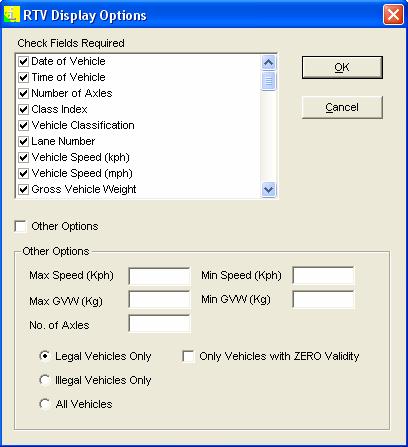
25 VBV Real Time View VBV Real Time Display Options..25..


26 Diagnostic Functions Sensor Waveform & Sensor Test Functions..26..
..27.")
27 Diagnostic Functions (Loop Signature Car)..27..


28 Axle Weight Band Limits Speed Band Limits..28..


29 Vehicle Classification Table (Axle Weight Limits Per Class) Class Gross Weight Limits..29..


30 ESA Calculation Parameters VBV Memory Allocation VBV Data Conversion..30..


31 HI-COMM 100 REPORT SAMPLES Reports Selection..31..
 Volume Per Class Per Lane.")
32 Reports Criteria (Selectable Time Periods) Volume Per Class Per Lane..32..


33 Average Speed Per Class Per Lane..33..


34 Volume Per Lane Group Per Time Band..34..
35 Axle Volume / Total Axle Weight / ESA Damage Factor Volume Per Speed Band Per Lane..35..
36 Traffic Volume Per Speed Band Per Time (Including Percentile Speed) Overloaded Vehicles Per Class Per Lane..36..


37 Statistical Data File Malfunction Management File ATMS Data File..37..
38 5 DRAWINGS Multiple HI-TRAC Installation Outstation System Configuration HI-TRAC 100 Front & Back Panels WIM Sensor Installation Piezo/Loop/Piezo A WIM/AVC Sensor Installation Inlaid Piezo Sensors C WIM/AVC Sensor Installation Loop/Piezo/Loop Lane WIM Layout A HI-TRAC Pre-Selection with CCTV/LPR Option BL Sensor Installation Loop Sensor Installation Roadside Cabinet General Layout High Speed Pre-Selection General Layout Low Speed Axle Weighing General Layout Pre-Selection & Weigh Station General Layout..38..
39 ..39..
40 ..40..
41 ..41..
42 ..42..
43 ..43..
44 ..44..
45 ..45..
46 ..46..
47 ..47..
48 ..48..
49 ..49..
50 DIVERT TO WEIGH STATION..50..
51 ..51..
52 ENTER WEIGHBRIDGE STATION..52..
HI-TRAC EMU TRAFFIC DATA MONITORING SYSTEM INCORPORATING VOLUMETRIC COUNTING TRAFFIC COUNTING AND CLASSIFYING AND HIGH SPEED WEIGH-IN-MOTION OVERVIEW
 HI-TRAC EMU TRAFFIC DATA MONITORING SYSTEM INCORPORATING VOLUMETRIC COUNTING TRAFFIC COUNTING AND CLASSIFYING AND HIGH SPEED WEIGH-IN-MOTION OVERVIEW TDC Systems Limited Weston-Super-Mare ENGLAND Tel :
BL PIEZO ELECTRIC SENSOR
 BL PIEZO ELECTRIC SENSOR INSTALLATION TDC Systems Limited Weston-Super-Mare ENGLAND Tel : +44 (0)1934 644299 Fax : +44 (0)1934 644255 Email : sales@tdcsystems.co.uk Web : www.tdcsystems.co.uk Introduction
Ton-Tel Multi-Deck Weighbridge
 Weighbridge Rugged construction, Accurate weights Weightel digital load cells from 6 tonnes to 30 tonnes capacity OIML Approved Plug-And-Weigh Proven reliability Weightel digital load cells for maximum
WEIGH IN MOTION AND DIRECT ENFORCEMENT
 WEIGH IN MOTION AND DIRECT ENFORCEMENT CrossWIM PRE-SELECTION AND ENFORCEMENT WEIGH-IN-MOTION CERTIFIED FOR DIRECT ENFORCEMENT Weigh-in-Motion and Direct Enforcement CrossWIM SIZE MEASUREMENT SENSOR LPR
SNMP dedicated to ORVALDI Solar Infini
 SNMP dedicated to ORVALDI Solar Infini User s Manual Management Software for Solar Inverter Table of Contents 1. 2. 3. Overview...1 1.1 Introduction...1 1.2 Features...1 1.3 Overlook...1 1.4 Installation
Superstatic 440. Static Heat Meter, Static Cooling Meter. Application
 Superstatic 440 Static Heat Meter, Static Cooling Meter Application Design The Superstatic 440 is a static heat or cooling meter according to standard EN1434 class 2 based on the fluid oscillation principle,
BRAKE TESTER DECELEROMETER
 OC3010_GBM_21009 BRAKE TESTER DECELEROMETER OWNER S MANUAL Version 8.++ ORBIT CONTROLS AG Zürcherstrasse 137 CH-8952 Schlieren/ZH Tel: + 41 44 730 2753 Fax: + 41 44 730 2783 info@orbitcontrols.ch www.orbitcontrols.ch
Integrated Traffic Services Ltd
 Integrated Traffic Services Ltd Specialist consultancy to the road traffic industry Right Of Weight HGV Priority at traffic signal junctions under MOVA Control Objective This paper briefly sets out a simple
Issue 2.0 December EPAS Midi User Manual EPAS35
 Issue 2.0 December 2017 EPAS Midi EPAS35 CONTENTS 1 Introduction 4 1.1 What is EPAS Desktop Pro? 4 1.2 About This Manual 4 1.3 Typographical Conventions 5 1.4 Getting Technical Support 5 2 Getting Started
Data Sheet Type FF420. Series 420 Specification Flange / Flange. Series 420 Non-Contact Rotary Torque Transducer
 Datum Electronics has further extended its standard range of torque transducers to cater for higher rotary speeds and an increased number of torque ranges. The 420 Series torque transducers operate with
Superstatic 440. Static Heat- and Cooling Meter. Application
 Superstatic 440 Static Heat- and Cooling Meter Application Design The Superstatic 440 is a static heat- and cooling meter according to standard EN1434 class 2 based on the fluid oscillation principle,
Commercial Vehicle Pre-Clearance and Compliance Best Practices. RANDY HANSON International Road Dynamics
 Commercial Vehicle Pre-Clearance and Compliance Best Practices RANDY HANSON International Road Dynamics Commercial Vehicle Compliance Best Practices Agenda Weigh Station Configurations Mainline, Ramp,
TECHNICAL DATA SHEET KVA UPS Systemss
 Återförsäljare: Tre Röda AB TillingeHagby 7-745 94 ENKÖPING Tel: 08-560 200 22 e-post: info@treroda.nu http: www.treroda.nu When the INSIDE is important make the OUTSIDE Cannon TECHNICAL DATA SHEET 400-500-600-800
Easily monitor road usage
 Easily monitor road usage Traffic data collection The key to a sustainably managed & well protected road infrastructure. KiTraffic Statistics system is easy and fast to install thanks to its pre-wired
Data Collection Technology at ARRB Transport Research
 Data Collection Technology at ARRB Transport Research Philip Roper 1 (Presenter) 1 ARRB Transport Research Biography Philip Roper joined ARRB Transport Research in May 2002. He holds a Bachelor of Engineering
Battery-Powered Flow Transmitter
 Data Sheet SS/AMAS/E Issue 3 Battery-Powered Flow Transmitter AquaMaster Explorer Widest flow range, highest accuracy measures minimal night and peak day flows Optional integral multi-speed, multichannel,
Performed by: Institute of Transportation Studies University of California, Irvine. Sponsored by: California Air Resources Board
 Performed by: Institute of Transportation Studies University of California, Irvine Sponsored by: California Air Resources Board Progress Meeting Dec 3rd, 2012 Outline Task Schedule Proposed Task Modifications
KEOR HP. THREE-PHASE UPS from 100 to 800 kva GLOBAL SPECIALIST IN ELECTRICAL AND DIGITAL BUILDING INFRASTRUCTURES
 KEOR HP THREE-PHASE from 100 to 800 kva GLOBAL SPECIALIST IN ELECTRICAL AND DIGITAL BUILDING INFRASTRUCTURES Legrand SUPERIOR PERFORMANCE SERVICE CONTINUITY AND ENERGY EFFICIENCY Legrand, world leader
TYPE 5867 PORTABLE Q METER
 IMPORTANT: Please read these instructions carefully before operating instrument SUBJECT TO CHANGE WITHOUT NOTICE This manual superseded all previous versions please keep for future reference TINSLEY, A
Simulating Trucks in CORSIM
 Simulating Trucks in CORSIM Minnesota Department of Transportation September 13, 2004 Simulating Trucks in CORSIM. Table of Contents 1.0 Overview... 3 2.0 Acquiring Truck Count Information... 5 3.0 Data
CHARACTERIZATION AND DEVELOPMENT OF TRUCK LOAD SPECTRA FOR CURRENT AND FUTURE PAVEMENT DESIGN PRACTICES IN LOUISIANA
 CHARACTERIZATION AND DEVELOPMENT OF TRUCK LOAD SPECTRA FOR CURRENT AND FUTURE PAVEMENT DESIGN PRACTICES IN LOUISIANA LSU Research Team Sherif Ishak Hak-Chul Shin Bharath K Sridhar OUTLINE BACKGROUND AND
Enhancing a Vehicle Re-Identification Methodology based on WIM Data to Minimize the Need for Ground Truth Data
 Enhancing a Vehicle Re-Identification Methodology based on WIM Data to Minimize the Need for Ground Truth Data Andrew P. Nichols, PhD, PE Director of ITS, Rahall Transportation Institute Associate Professor,
Oregon DOT Slow-Speed Weigh-in-Motion (SWIM) Project: Analysis of Initial Weight Data
 Project: Analysis of Initial Weight Data") Portland State University PDXScholar Center for Urban Studies Publications and Reports Center for Urban Studies 7-1997 Oregon DOT Slow-Speed Weigh-in-Motion (SWIM) Project: Analysis of Initial Weight Data
Portland State University PDXScholar Center for Urban Studies Publications and Reports Center for Urban Studies 7-1997 Oregon DOT Slow-Speed Weigh-in-Motion (SWIM) Project: Analysis of Initial Weight Data
Fortress 1 Outdoor Emergency Central Lighting Inverter (CLI) Technical Specifications
 Technical Specifications") Fortress 1 Outdoor Emergency Central Lighting Inverter (CLI) Technical Specifications PART 1 GENERAL 1.1 SUMMARY A. This specification describes a single phase, on-line, double conversion, solid state
Fortress 1 Outdoor Emergency Central Lighting Inverter (CLI) Technical Specifications PART 1 GENERAL 1.1 SUMMARY A. This specification describes a single phase, on-line, double conversion, solid state
KEOR HP. THREE-PHASE UPS from 100 to 800 kva GLOBAL SPECIALIST IN ELECTRICAL AND DIGITAL BUILDING INFRASTRUCTURES
 KEOR HP THREE-PHASE from 100 to 800 kva GLOBAL SPECIALIST IN ELECTRICAL AND DIGITAL BUILDING INFRASTRUCTURES Legrand SUPERIOR PERFORMANCE SERVICE CONTINUITY AND ENERGY EFFICIENCY Legrand, world leader
Power Lynx 3 Uninterruptible Power System (UPS) Technical Specifications
 Technical Specifications") Power Lynx 3 Uninterruptible Power System (UPS) Technical Specifications PART 1 GENERAL 1.1 SUMMARY A. This specification describes a three phase, on-line, double conversion, solid state Uninterruptible
Power Lynx 3 Uninterruptible Power System (UPS) Technical Specifications PART 1 GENERAL 1.1 SUMMARY A. This specification describes a three phase, on-line, double conversion, solid state Uninterruptible
ML Maximum Power Point Tracking (MPPT) Series ML2420-ML2430-ML2440 Solar Charge and Discharge Controller
 Series ML2420-ML2430-ML2440 Solar Charge and Discharge Controller") ML Maximum Power Point Tracking (MPPT) Series ML2420-ML2430-ML2440 Solar Charge and Discharge Controller Product Features With the advanced dual-peak or multi-peak tracking technology, when the solar panel
ML Maximum Power Point Tracking (MPPT) Series ML2420-ML2430-ML2440 Solar Charge and Discharge Controller Product Features With the advanced dual-peak or multi-peak tracking technology, when the solar panel
Introduction. Traffic data collection. Introduction. Introduction. Traffic stream parameters
 Introduction Traffic data collection Transportation Systems Engineering Outline Point measurement Measurement over a short stretch Measurement over a long stretch Measurement over an area 20080813 Traffic
Inlet Controller TC5-ITA USER'S MANUAL. M rev. 02 K rev. 00
 Inlet Controller TC5-ITA USER'S MANUAL M 890-00047 rev. 02 K 895-00458 rev. 00 TABLE OF CONTENTS PRECAUTIONS... 3 FEATURES... 4 LOCATION OF THE CONTROLS... 5 Status Leds...5 Internal Switches...6 INSTALLATION
Journey into quality for traffic monitoring equipment. Short session monitoring operations
 Journey into quality for traffic monitoring equipment Short session monitoring operations Introduction Quality assurance/quality control for short session portable equipment. Historically, quality assurance/quality
Fortress 3 Harsh. Harsh Environment. Emergency Central Lighting Inverter (CLI) Technical Specifications
 Technical Specifications") Fortress 3 Harsh Emergency Central Lighting Inverter (CLI) Technical Specifications PART 1 GENERAL 1.1 SUMMARY A. This specification describes a three phase, on-line, double conversion, solid state Lighting
Fortress 3 Harsh Emergency Central Lighting Inverter (CLI) Technical Specifications PART 1 GENERAL 1.1 SUMMARY A. This specification describes a three phase, on-line, double conversion, solid state Lighting
RF80-K Aircraft Battery Charger / Analyzer
 RF80-K Aircraft Battery Charger / Analyzer Features Automatic Operation Heavy Duty Design And Performance Digital Timing / Display Charges And Analyzes Aircraft Batteries (3-75 AH) One-hour Main Charge,
Cobra 3 Stand-By Emergency Central Lighting Inverter (CLI) Technical Specifications
 Technical Specifications") Cobra 3 Stand-By Emergency Central Lighting Inverter (CLI) Technical Specifications PART 1 GENERAL 1.1 SUMMARY A. This specification describes a stand-by, three-phase, solid state Lighting Inverter System
Cobra 3 Stand-By Emergency Central Lighting Inverter (CLI) Technical Specifications PART 1 GENERAL 1.1 SUMMARY A. This specification describes a stand-by, three-phase, solid state Lighting Inverter System
ASPIRO & GUARDIAN BATTERY MANAGEMENT WITH ACC EXTENDED CONTROLLER
 DESCRIPTION Battery management is implemented in the Aspiro and Guardian DC Power Systems using the ACC Extended (ACX) controller. ASPIRO & GUARDIAN BATTERY MANAGEMENT WITH ACC EXTENDED CONTROLLER The
TomTom WEBFLEET Contents. Let s drive business TM. Release note
 TomTom WEBFLEET 2.17 Release note Contents Extended WEBFLEET Reporting 2 Reporting Diagnostic Trouble Codes 3 Security features 5 Invoice only interface 7 Default trip mode 8 Navigation map information
AX900 AXLESCALESERIES
 AX900 Efficiency, cost effectiveness, reliability, durability and accuracy... These are just a few of the transportation industry s demands for weighing systems. CLASS IIII CERTIFICATE #01-053A1 ISO 9001
INSTRUCTION MANUAL ANCHOR LOAD CELL. Model ANCLO
 INSTRUCTION MANUAL ANCHOR LOAD CELL Model ANCLO Roctest Limited 2009. All rights reserved This product should be installed and operated only by qualified personnel. Its misuse is potentially dangerous.
CurveMaker HD v1.0 2Ki Programmable Ignition programming software
 Contents CurveMaker HD v1.0 2Ki Programmable Ignition programming software Dynatek 164 S. Valencia St. Glendora, CA 91741 phone (626)963-1669 fax (626)963-7399 page 1) Installation 1 2) Overview 1 3) Programming
Hi-Z USB Wireless. Introduction/Welcome
 Hi-Z USB Wireless Introduction/Welcome Thank you for selecting the Hi-Z Antennas USB Wireless system. The Hi-Z USB Wireless system provides control functions from a personal computer to operate a Hi-Z
TRITON ERROR CODES ERROR CODE MODEL SERIES DESCRIPTION RESOLUTION
 0 8100, 9100, 9600, 9610, 9615, 9640, No errors 9650, 9700, 9710, 9705, 9750, RL5000 (SDD),RL5000 (TDM), RT2000, 9800, MAKO, SuperScrip 1 9615 Unsolicited note channel 1 2 9615 Unsolicited note channel
TOWER MAXI T SINGLE CONVERSION ON LINE UPS SYSTEMS
 INSTRUCTION MANUAL TOWER MAXI T SINGLE CONVERSION ON LINE UPS SYSTEMS September 2000 TOWER UPS DISTRIBUTION (PTY) LTD 1 1. INTRODUCTION T A B L E O F C O N T E N T S 1.1 General Description... 3 1.2 Features...
ZT-USB Series User Manual
 ZT-USB Series User Manual Warranty Warning Copyright All products manufactured by ICP DAS are under warranty regarding defective materials for a period of one year, beginning from the date of delivery
Overview of operation modes
 Overview of operation modes There are three main operation modes available. Any of the modes can be selected at any time. The three main modes are: manual, automatic and mappable modes 1 to 4. The MapDCCD
Engineering Dept. Highways & Transportation Engineering
 The University College of Applied Sciences UCAS Engineering Dept. Highways & Transportation Engineering (BENG 4326) Instructors: Dr. Y. R. Sarraj Chapter 4 Traffic Engineering Studies Reference: Traffic
Traffic Data For Mechanistic Pavement Design
 NCHRP 1-391 Traffic Data For Mechanistic Pavement Design NCHRP 1-391 Required traffic loads are defined by the NCHRP 1-37A project software NCHRP 1-39 supplies a more robust mechanism to enter that data
USES OF ANPR DATA IN TRAFFIC MANAGEMENT AND TRANSPORT MODELLING ABSTRACT
 USES OF ANPR DATA IN TRAFFIC MANAGEMENT AND TRANSPORT MODELLING A ROBINSON and A VAN NIEKERK* Hatch Goba (Pty) Ltd, Private Bag X20, Gallo Manor Tel: 011-239-5614; Email: robinsona@hatch.co.za *South African
Appendix 3. DRAFT Policy on Vehicle Activated Signs
 Appendix 3 DRAFT Policy on Vehicle Activated Signs Ealing Council has been installing vehicle activated signs for around three years and there are now 45 across the borough. These signs help to reduce
52.1 SNOW REMOVAL AND ICE CONTROL (TRUCK)
") 52.1 SNOW REMOVAL AND ICE CONTROL (TRUCK) 52.1.1 GENERAL The Work consists of loading trucks, snowplowing and the application of sand, salt or a sand and salt mixture to roadway surfaces. 52.1.2 MATERIALS
52.1 SNOW REMOVAL AND ICE CONTROL (TRUCK) 52.1.1 GENERAL The Work consists of loading trucks, snowplowing and the application of sand, salt or a sand and salt mixture to roadway surfaces. 52.1.2 MATERIALS
MiX 2310i with IP Housing. P r o d u c t I n f o r m a t i o n G u i d e
 MiX 2310i with IP Housing P r o d u c t I n f o r m a t i o n G u i d e VISION 2 The MiX 2310i extends the MiX Telematics range of fleet tracking hardware, complementing the FM Communicator and FM Tracer
Operation manual. ABS 911 GT3 Cup Gen.II MTH Version _V1_2018/02
 Operation manual ABS MTH355200 Version _V1_2018/02 Contact Manthey-Racing GmbH Technical Support Rudolf-Diesel-Str. 11-13 53520 Meuspath Germany Phone: +49 (0) 2691 9338 807 E-Mail: techsupport@manthey-racing.de
UPGRADE YOUR BLOW MOLDING MACHINE WITH ONE OF OUR TWO NEW STATE OF THE ART MACHINE CONTROL SYSTEMS.
 UPGRADE YOUR BLOW MOLDING MACHINE WITH ONE OF OUR TWO NEW STATE OF THE ART MACHINE CONTROL SYSTEMS. Uniloy is proud to introduce the Allen Bradley Compact Logix, and B&R Control Packages developed for
PowerSTAR PS-2024-D. Maximum Power Point Tracking Solar Regulator. w w w. r o c s o l i d. c o m. a u. Contents
 w w w. r o c s o l i d. c o m. a u PowerSTAR PS-2024-D Maximum Power Point Tracking Solar Regulator Contents 1 Quick Start Guide... 2 2 Specifications... 3 2.1 General Operation... 3 2.2 Absolute Maximum
D. Operation and Maintenance Data. In addition to items specified in Division 1 Section "Operation and Maintenance Data," include the following:
 SECTION 16211 - ELECTRICITY METERING PART 1 - GENERAL 1.1 RELATED DOCUMENTS A. Drawings and general provisions of the Contract, including General and Supplementary Conditions and Division 1 Specification
AN The SmartSensor HD as an Automatic Traffic Recorder. Automatic Traffic Recorders
 AN-0006 The SmartSensor HD as an Automatic Traffic Recorder The Wavetronix SmartSensor HD can be used as an automatic traffic recorder (ATR) in the process of gathering, storing and analyzing traffic data.
AXINET BATTERY MANAGEMENT SYSTEM. system for monitoring and controlling the performance of charger stations
 system for monitoring and controlling the performance of charger stations BATTERY CHARGERS and POWER SUPPLIES for INDUSTRIAL APPLICATIONS AXInet is a system that optimizes the operation of charging stations
OPERATING INSTRUCTIONS MCP-MT1
 OPERATING INSTRUCTIONS MCP-MT1 MRM PROCOM Pvt Ltd ISO-9001-2008 certified organization Plot No. : 20-21, Industrial Estate, Sector - 59, Phase-II, Faridabad (Haryana) Ph.: 0129-4700400(10 Lines) Email:
BMS16. Thanks for your purchasing the BMS16 for your vehicle.
 BMS16 BMS for 2S-16S LiPo & LiFe Low power consumption High accuracy 2.8 TFT LCD display Programmable Thanks for your purchasing the BMS16 for your vehicle. Read the ENTIRE instruction manual to become
Marsh McBirney Flo-Dar
 Marsh McBirney Flo-Dar Accurate Flow Measurement Flo-Dar TM provides the user with highly accurate flow measurements under a wide range of flows and site conditions. By measuring the velocity of the fluid
CurveMaker DFS v2.0 Dyna FS Ignition Programming Software
 CurveMaker DFS v2.0 Dyna FS Ignition Programming Software Contents Dynatek 164 S. Valencia St. Glendora, CA 91741 phone (626)963-1669 fax (626)963-7399 page 1) Installation 1 2) Overview 1 3) Introduction
Upgrade your blow molding machine with one of our two new state of the art machine control systems.
 Upgrade your blow molding machine with one of our two new state of the art machine control systems. Uniloy is proud to introduce the Allen Bradley Compact Logix, and B&R Control Packages developed for
Electronic Logging Device (ELD) Rule
 Rule") Electronic Logging Device (ELD) Rule Paper RODS Log Book Definitions Logging Software a computer software program of application on a phone or tablet that does not comply with 395.15. Not connected to
Electronic Logging Device (ELD) Rule Paper RODS Log Book Definitions Logging Software a computer software program of application on a phone or tablet that does not comply with 395.15. Not connected to
Defender Mini Online Emergency Central Lighting Inverter (CLI) Technical Specifications
 Technical Specifications") Defender Mini Online Emergency Central Lighting Inverter (CLI) Technical Specifications PART 1 GENERAL 1.1 SUMMARY A. The Defender Mini CLI specification describes a single phase, online, solid state Lighting
Defender Mini Online Emergency Central Lighting Inverter (CLI) Technical Specifications PART 1 GENERAL 1.1 SUMMARY A. The Defender Mini CLI specification describes a single phase, online, solid state Lighting
OVERVIEW OF CONTROLS
 π H-5819, H-5820 H-5821, H-5822 DELUXE COUNTING SCALE 1-800-295-5510 uline.com OVERVIEW OF CONTROLS DISPLAY DEFINITIONS # NAME DESCRIPTION 1 DISPLAY 2 1 3 STABLE 4 RECHARGE PAGE 1 OF 8 Displays the total
SentryGOLD Fully-Automated Fuel Management System
 SentryGOLD Fully-Automated Fuel Management System Trak s SentryGOLD Fully Automated Fuel Management System provides the highest level of security for your fleet and the highest level of accuracy for your
VLT S INTELLIGENT TEST LANE CONCEPT
 VLT S INTELLIGENT TEST LANE CONCEPT VLT, a world-wide specialist in the field of vehicle testing, has introduced its Intelligent Test Lane Concept in 1995 and is continuously updating this concept, whereby
Welcome to ABB machinery drives training. This training module will introduce you to the ACS850-04, the ABB machinery drive module.
 Welcome to ABB machinery drives training. This training module will introduce you to the ACS850-04, the ABB machinery drive module. 1 Upon the completion of this module, you will be able to describe the
Pulsar EXtreme 2200C / 3200C
 www.mgeups.com MGE UPS SYSTEMS Pulsar EXtreme 00C / 300C Installation and user manual P O W E R P R O V I D E R L E I B E R R U P T N T N I E U T H 3400753EN/AA - Page Introduction Thank you for selecting
BM14200 Roller Brake Tester
 BM14200 Roller Brake Tester The perfect choice if you are looking for... Roller Brake Tester designed to last. The most comprehensive Load Simulation System Program and EBS Diagnosing tool. Roller Brake
EZS. Motorized Linear Slides. Series. RoHS-Compliant
 RoHS-Compliant Motorized Linear Slides EZS Series AUDIN -, avenue de la malle - 5137 Saint Brice Courcelles - Tel : 3...1 - Fax : 3... - Web : http: www.audin.fr - Email : info@audin.fr RoHS-Compliant
REVISION HISTORY REVISION HISTORY
 FILTER CONTROLLER REVISION HISTORY Filter Flush Controller forms part of the Netafim range of filtration controllers all designed to make filteration more reliable and economical.. Contact any of the Netafim
One-Stop Service: Monitoring and Managing.
 One-Stop Service: Monitoring and Managing. The highest quality from the market leader Solar-Log devices are the most accurate and reliable data loggers on the market. Offer your customers high-quality
Automated Seat Belt Switch Defect Detector
 pp. 10-16 Krishi Sanskriti Publications http://www.krishisanskriti.org/publication.html Automated Seat Belt Switch Defect Detector Department of Electrical and Computer Engineering, Sri Lanka Institute
Easily monitor road usage
 Easily monitor road usage Traffic data collection The key to a sustainably managed & well protected road infrastructure. Typical use: direct automated enforcement at high speeds. KiTraffic Statistics system
SecureUPS On-Line 120V AC Output, 1300VA
 SecureUPS On-Line 120V AC Output, 1300VA Trusted Power Protection Solution for Intelligent Transportation Systems (ITS) Challenges Intelligent transportation systems (ITS) are using innovative traffic
Lester Electrical ChargerConnect App User s Guide
 Lester Electrical ChargerConnect App User s Guide Lester Electrical Summit Series II chargers features Bluetooth wireless communication, which can be accessed using an Apple or Android smart phone, tablet,
OPERATING INSTRUCTIONS FOR SLIDING DOOR RETROFIT CONTROLLER DC-02
 OPERATING INSTRUCTIONS FOR SLIDING DOOR RETROFIT CONTROLLER DC-02 1. INTRODUCTION 2. SAFETY INSTRUCTIONS 3. SPECIFICATION 4. OPERATING INSTRUCTIONS AND CONTROL FUNCTIONS 5. SET UP PROCEDURE 6. CONNECTIONS
Uninterruptible Power System
 USER'S MANUAL Emergency Backup Power Supply For Use With Computer Loads Only Power Surge/Noise Protection Intelligent Auto-Shutdown Software Internet Line Protection Cost Efficiency AVR Protection Compact
APPLICATION NOTE
 12/18/02 Getting started using with a brushless motor Problem: For new users of an intelligent drive, starting to implement a motion control application can be a quite complex task. You need to know how
ReadStar & CapStar Range Torque Readouts & Torque Testers. Crane Electronics Inc The force in torque management
 ReadStar & CapStar Range Torque Readouts & Torque Testers Crane Electronics Inc The ReadStar range enables the measurement and collection of torque data. The ReadStar range comprises ReadStar II, ReadStar
BMS24. Thanks for your purchasing the BMS24 for your vehicle.
 BMS24 for 2S-24S LiPo & LiFe Low power consumption High accuracy 2.8 TFT LCD display Programmable Thanks for your purchasing the BMS24 for your vehicle. Read the ENTIRE instruction manual to become familiar
General Purpose Ignition System GS6. User Manual. Document No PS-0009
 General Purpose Ignition System GS6 User Manual Document No. 1521-PS-0009 Gill Instruments Ltd Saltmarsh Park, 67 Gosport Street, Lymington, Hampshire, SO41 9EG, UK Tel: +44 1590 613500 Fax: +44 1590 613555
Advanced User Manual
 Advanced User Manual Banks SpeedBrake For use with Palm Tungsten E2 2004-2005 Chevy/GMC 6.6L (LLY) Turbo-Diesel Pickup THIS MANUAL IS FOR USE WITH KITS 55419 & 55421 Gale Banks Engineering 546 Duggan Avenue
Vanpool Regional Administration
 Vanpool Regional Administration Contents Introduction... 2 Structure and Layout... 2 Make sure you are in the right application... 3 Vanpool Program Configuration... 3 Lookup... 5 Adding a new van... 6
SmartON / SmartON+ Installation and Use Manual
 SmartON / SmartON+ Installation and Use Manual Rev. Date Ver. Ver. Notes document document SmartON SmartViewII 1.0 06/04/2007 3.08 2.30 Pre-release 1.01 10/04/2007 3.08 2.30 Release 1.02 04/10/2007 3.09
Sentinel Panametrics Custody Transfer Gas Ultrasonic Flowmeter
 GE Measurement & Control Sentinel Panametrics Custody Transfer Gas Ultrasonic Flowmeter Applications The Sentinel flowmeter is a complete ultrasonic flowmeter system for the measurement of natural gas
WHEEL LOAD SCALES THE PURCHASING DECISION GUIDE
 WHEEL LOAD SCALES THE PURCHASING DECISION GUIDE The term wheel weigher covers a wide range of products and prices and it is important to understand the competitive benefits and limitations of the various
Tyre Pressure Monitoring System (TPMS)
") Tyre Pressure Monitoring System (TPMS) The Snooper Tyre Pilot application can monitor up to 22 tyres simultaneously, there are various kits and sensors available from your Snooper dealer or from www.snooper.co.uk.
Tyre Pressure Monitoring System (TPMS) The Snooper Tyre Pilot application can monitor up to 22 tyres simultaneously, there are various kits and sensors available from your Snooper dealer or from www.snooper.co.uk.
Ch 4 Motor Control Devices
 Ch 4 Motor Control Devices Part 1 Manually Operated Switches 1. List three examples of primary motor control devices. (P 66) Answer: Motor contactor, starter, and controller or anything that control the
Table of Contents 1. INTRODUCTION GENERAL INFORMATION-ABOUT OBDII/EOBD PRODUCT DESCRIPTIONS OPERATIONS...11
 Table of Contents 1. INTRODUCTION...1 2. GENERAL INFORMATION-ABOUT OBDII/EOBD...1 2.1 ON-BOARD DIAGNOSTICS (OBD) II...1 2.2 DIAGNOSTIC TROUBLE CODES (DTCS)...2 2.3 LOCATION OF THE DATA LINK CONNECTOR (DLC)...3
DATUM ELECTRONICS RS425 NON-CONTACT TORQUE TRANSDUCER PRODUCT OVERVIEW
 DATUM ELECTRONICS LIMITED TELEPHONE: +44 (0) 1983 28 28 34 FAX: +44 (0) 1983 28 28 35 EMAIL: support@datum-electronics.co.uk WEB: www.datum-electronics.co.uk DATUM ELECTRONICS RS425 NON-CONTACT TORQUE
INSTALLATION INFORMATION
 INSTALLATION INFORMATION BMS ZE6000i-PCBT.xxxx / ver. 2 Programmable battery management system for Lithium Ion battery cells, for up to 32 round or prismatic cells, 10 to 400Ah NOTE: This installation
1000 KW / 1250 KVA POWERED by
 1000 KW / 1250 KVA POWERED by MODEL Triton Power is a world leader in the design, manufacture of stationary, mobile and rental generator sets and Power Modules from 10 to 2000 kw. Through our commitment
DLRO 10 and DLRO 10X. Digital Microhmmeter. DLRO 10 and DLRO 10X Digital Microhmmeter. NEW interchangeable test lead terminations
 DLRO 10 and DLRO 10X DESCRIPTION NEW interchangeable test lead terminations Auto current reversal cancels standing emfs Protected to 600 V Automatically detects continuity in potential and current connections
Est Battery Data Logger BDL3000
 Est.1968 Battery Data Logger BDL3000 Concept The Thycon Battery Data Logger (BDL) measures, stores, displays and analyses multiple battery parameters continually without user intervention. The BDL combines
After opening the printer drawer, the data plate is visible showing 'e1 84'. Any printer paper used must also show on the reverse side "e1 84".
 DRIVERS SHORT OPERATING INSTRUCTIONS DTCO 1381 Display and Operating Elements Display Menu button Tear-off edge Driver 1 keypad Card slot 1 Download interface Driver 2 keypad Card slot 2 Unlock button
CONNECTED SERVICEs TACHOGRAPH SOLUTIONS
 CONNECTED SERVICEs TACHOGRAPH SOLUTIONS COMPLIANCE MADE EASY Knowing how your drivers are working and how your trucks are being utilised is not just good business practice; it is the law. Vehicle and driver
тел.: +375(1771) e mail: Fuel level sensors eurosens Dominator
 e mail: Fuel level sensors eurosens Dominator") тел.: +375(1771)7 13 00 e mail: office@mechatronics.by Fuel level sensors eurosens Dominator Application The devices are used in vehicle tanks and stationary capacities for fuel level measurement. The
тел.: +375(1771)7 13 00 e mail: office@mechatronics.by Fuel level sensors eurosens Dominator Application The devices are used in vehicle tanks and stationary capacities for fuel level measurement. The
Temperature Controller OVATION 214 User's Guide
 Temperature Controller User's Guide Read this guide carefully before using the controller. 890-00045 rev.00 TABLE OF CONTENTS Page TABLE OF CONTENTS... 2 PRECAUTIONS... 3 FEATURES... 4 LOCATION OF THE
OBI-M2. Compact and Rugged Combustion Analysis System for use on Vehicles, Motorbikes and Test Benches
 OBI-M2 Compact and Rugged Combustion Analysis System for use on Vehicles, Motorbikes and Test Benches OBI-M2 is an extremely compact and fully featured combustion analysis system suitable for use on test
Illuminator Series CM. GUIDE SPECIFICATIONS And TECHNICAL DESCRIPTION. 500W, 1000W, 1500W and 2000W Single-Phase Emergency Power System
 Illuminator Series CM GUIDE SPECIFICATIONS And TECHNICAL DESCRIPTION 500W, 1000W, 1500W and 2000W Single-Phase Emergency Power System This description contains all the necessary functional and technical