Johnson Product Catalog Johnson Product Catalog. Strength Through Innovation Since 1764
|
|
|
- Ferdinand Snow
- 6 years ago
- Views:
Transcription

1


2 2015 Johnson Product Catalog 2015 Johnson Product Catalog Strength Through Innovation Since 1764


3 Company History Gunnebo Industries is a global leading manufacturer of products such as crane blocks, wire rope sheaves, chain & lifting components, shackles and lashing products, which are exclusively produced in Sweden, Norway and USA. The company was founded in 1764 in Sweden and has since then lead the development in the lifting industry. We have subsidiaries in 10 countries covering every continent, as well as distributing partners in more than 50 countries. This makes Gunnebo Industries a truly international company. Gunnebo Johnson Corporation has a long and storied history as well, with deep roots in the oilfield, dating back to Isaac N. Hinderliter began the business and patented certain oil rig elevators in In 1919, his son Frank J. Hinderliter founded the Hinderliter Tool Company in Tulsa, Oklahoma. The company would eventually hold nearly one hundred patents, and began by manufacturing cable and rotary tools for the cable tool drilling rigs of the era. By pioneering new heat treatment processes, the company and its products became renowned for high quality. In 1939, at the beginning of World War Two, the company received U. S. government contracts to produce gun barrels for use by the Allies and to add to the U. S. military buildup. The company began its own heat treatment operation at that time in order to have an integrated manufacturing process. After the war ended, the company was sold to H. K. Porter in A new company was formed, called Don R. Hinderliter Incorporated, and production of wellheads along with commercial heat treatment was started. The company evolved into Hinderliter Energy Equipment Corporation in the late 1940s, still located in Tulsa, Oklahoma. A small local company, Johnson Blocks, joined the group in 1962, adding oilfield blocks to the wellhead line, along with several other oilfield products. Soon after, construction and crane blocks were added to the product lines. The company became Hinderliter Management Systems in 1977, and in 1981 Johnson Blocks became The Johnson Manufacturing Company, alongside Hinderliter Heat Treatment, both subsidiaries. By 1988 major changes occurred. Hinderliter Heat Treatment was sold, and so was Johnson Manufacturing. Johnson Manufacturing became part of Gunnebo AB of Sweden, and was renamed Gunnebo Johnson Corporation. Premium quality Gunnebo chain and forged lifting accessories were now marketed together with Johnson blocks in North America and around the world. The company became a public entity in 2005, listed on the Swedish Stock Exchange. In 2008, the group again became private when purchased by the Segulah Group of Sweden. It has since continued to operate its Gunnebo and Johnson brands globally, utilizing its network of manufacturing and distribution systems. Copyright 2014 Gunnebo Industrier AB All rights reserved. E&OE
4 Introduction 1-17 Shorty J Quick Reeve Scrap Handling Blocks Overhaul Balls Swivels Wedge Sockets Snatch Blocks Oilfield Blocks Tilt Wall Blocks Bail Blocks Wire Rope Sheaves Special Engineered Products : Failure to read, understand and comply with the following instructions, working load limits and specifications in this publication may result in serious injury or damage to property. 1

5 Where there is growth and development in the world......gunnebo Industries products can be found. 2
6 Table of Contents History...Inside cover Terminology General Precautions Rigging Inspection and Maintenance Jaw/Eye Swivels Eye/Jaw Swivels Product Warnings/Inspection Instructions Latches, Latch Kits Wedge Sockets J-Block Crane Blocks...18 Contents, Introduction, Features & Benefits One Sheave Shorty J Crane Blocks Two Sheave Shorty J Crane Blocks Three Sheave Shorty J Crane Blocks Four Sheave Shorty J Crane Blocks Five Sheave Shorty J Crane Blocks Six Sheave Shorty J Crane Blocks Seven Sheave Shorty J Crane Blocks Eight Sheave Shorty J Crane Blocks...67 Shorty J Crane Block Options Flexi-Weight Blocks...75 Warnings and Use Limitations Quick Reeve Crane Blocks...78 Contents, Introduction, Features and Benefits Products and Specifications Safety Advisory...87 Reeving Instructions...88 Scrap Handling Blocks Snatch Blocks Contents, Introduction, Features and Benefits One Sheave Snatch Blocks with s One Sheave Snatch Blocks with Shackles One Sheave Snatch Blocks Tailboard Blocks One Sheave Snatch Blocks Top Dead End with s One Sheave Snatch Blocks Top Dead End with Shackles Two Sheave Snatch Blocks with s Two Sheave Snatch Blocks with Shackles Snatch Blocks Warnings and Use Limitations Oilfield Blocks Contents Hay Fork Pulleys Tong Line Blocks Laydown Blocks Guyline Blocks Manhandler Derrick & Personnel Lifting Blocks Manhandler Warnings and Use Limitations Tubing Blocks Overhaul Balls...92 Contents, Introduction, Features & Benefits Midget Non-Swiveling Overhaul Balls...95 Midget Swiveling Overhaul Balls...96 Bottom Swivel Overhaul Balls Top Swivel Overhaul Balls Overhaul Ball Options Warnings and Use Limitations Swivels Contents, Introduction, Features & Benefit Eye/ Swivels Jaw/ Swivels Eye/Eye Swivels Jaw/Jaw Swivels Tilt Wall Blocks Bail Blocks Wire Rope Sheaves Contents, Introduction, Features and Benefits Forge Fab Sheaves Finish Bore Sheaves Bronze Bushed Sheaves Roller Bearing Sheaves Tapered Roller Bearing Sheaves Sheave Hub and Lubrication Options Specially Engineered Products


7 Terminology Chemical Analysis (Chemical Test) The process used to identify the percentage of various elements which make up a given metal. Today s most commonly used alloy is steel, the simplest compound of which is iron with 1% or less of carbon. Most steel, however, contains alloying elements such as chromium, manganese, nickel, tungsten, vanadium and others. Design Factor A theoretical reserve capability often mis-titled Safety Factor. It is computed by dividing the Ultimate Load by the Working Load Limit. Example: (Ultimate Load) 100 Ton Design Factor of 4, = (SWL) 25 Ton or ratio of 4 to 1 Flame Hardening A high heat/quick cool process used to harden that portion of the sheave groove which supports the wire rope. Grooves flame hardened to a minimum Rockwell C 35 are standard on all sheave sizes 16 inches O.D. and larger. (Prices on smaller sheaves available upon application.) Fleet Angle The degree to which a rope varies from true center (0º) in passing from drum to sheave or from one sheave to another. Too great a fleet angle will cause the line to wind unevenly on the winch drum. Too small a fleet angle will cause the line to pile up. In sheave-to-sheave applications such as those utilizing upper and lower blocks, the fleet angle will be increased: a) when there is more space between the sheaves of one block than those of the other: b) when the two blocks are drawn in close proximity to one another. 1. Side Plates 2. Center Plates 3. Mouse Ear Deadend 4. Upper Tie Bolts 5. Center Pin 6. Cheek Weight 7. Safety Precautions Plate: Tonnage Rating Nameplate (Opposite sides) 8. Lower Tie Bolts 9. Cheek Weight Cap Screw(s) (1 or 2) 10. Trunnion Pin, or Housing Trunnion Latch 13. Housing 14. Thrust Bearing 15. Nut 16. Wire Rope Sheaves To minimize rope and equipment wear, the following generally accepted fleet angle limits should be observed. Sheave-to-Sheave: 2.5º maximum Sheave-to-Smooth Drum: 1/2º minimum to 2º maximum Sheave-to-Grooved Drum: 1/2º minimum to 1-1/2º maximum Housing Often referred to fas Trunnion and Cross Head. The so-called Housing Pin is actually not a pin at all, but an integral part of the housing. On most Gunnebo Johnson Manufacturing products, it is the Housing that allows the hook to swing as well as swivel. Mechanical Properties (Mechanical Test) Those properties of a material which reveal its reaction to an applied force, and thereby, its applicability to a given task. Considered, for example, are the modulus of elasticity, tensile strength, elongation, hardness and fatigue limit. Outside Diameter (O.D.) The diameter of a circular object as measured from its outermost edges. Overhaul That amount of downfall weight sufficient to overcome sheave bearing friction, winch-to-boom-tip line weight and other counter-fall factors inherent in the crane system. 4 Terminology

8 Terminology Pitch Diameter (P.D.) A true measure of the bend of the rope around the sheave, and represented by the distance between the center of the rope on one side of the sheave and the center of the rope on the other. P.D. differs from Tread Diameter (T.D.) which takes its measurement from the deepest point of the sheave groove. Formula: P.D. = T.D. + Nominal Rope Size. Proof Load This factor refers to the average load to which a product may be subjected before visible deformation occurs. Also, to the load applied in performance of a Proof Test. Proof Test A tensile strength test applied solely for the purpose of detecting defects in materials, product design or assembly. (Gunnebo Johnson Manufacturing offers Proof Test capabilities for any products it manufactures. Prices available upon request.) Working Load Limit Sometimes referred to as SWL, Working Load, Working Load Limit, and Rated Load Value. Indicates the maximum load to which a product should be subjected. The term applies only to static loads held firmly in direct tension. It does not include torsional, binding, offset, or shock load factors. Shock Load A significantly increased load factor caused by the sudden shift, jerk, or impacting of the load. Short Ton The avoirdupois weight on which Gunnebo Johnson Manufacturing product capacities are based. Commonly used throughout the U.S. and Canada, the term implies a weight of 2,000 pounds and differs from long ton, which amounts to 2,240 pounds. Tread Diameter (T.D.) Measurement from deepest point of the sheave groove on one side of sheave to deepest point of sheave groove on other side. Ultimate Load Indicates the point as which the product fails, or will no longer support the load. Yield Point The point between proof load and ultimate at which permanent deformation occurs. Note that this deformation may or may not be visible. Short Tons Metric Tons Short Tons Metric Equivalants Metric Tons Short Tons Metric Tons Nominal Wire Rope Size (Inches) /8 9.5 Nominal Wire Rope Size (mm) / / / / / / / / / / / / / / / Terminology 5
9 General Precautions Stay within the Working Load Limits of all Gunnebo Johnson products. The Working Load Limits assigned Gunnebo Johnson products reflect our best engineering assessment. They should never be exceeded, regardless of the strength of the wire rope being used. Nor will we accept responsibility for any rating request which would result in a lower design factor than that we judge to be adequate. (See design factors indicated in this catalog. Standard: 4 to 1.) Note that Working Load Limits apply only to loads held uniformly in direct tension. They do not apply to shock loads, which can multiply the static weight factor many times over. Likewise, they do not allow for hook tip loading, side loading, or for bending, torsional and related loads. Note also that Working Load Limits apply only to new products as they are shipped from the factory. Age, type of service and environmental conditions can subsequently affect these limits, and periodic tests should be undertaken to assure the product will perform in accord with existing regulations and sound operating practices. Do not misuse Gunnebo Johnson Blocks hook latch attachments. Gunnebo Johnson Blocks hook latch kits are designed solely for loose sling retention. They are not antifouling devices, and caution must be exercised to prevent a latch from supporting any portion of the load. Protect the latch, and thereby the workmen below, by: 1) continuous inspection to see that the latch is undamaged, in place, and properly centered on the hook; 2) taking care not to crowd the latch with over-sized ropes or stiff riggings; making sure the load is properly seated prior to each lift. Use caution in applying standard Gunnebo Johnson products to severe vibration or sharp-blow situations. Activities such as pile driving can have adverse effects upon the life of the product and, therefore, may not be covered by the warranty. Standard cheek weights and overhaul balls, for example, are not designed as load-bearing members. They can break under extreme vibration or sharp blows. Severe working conditions can also create problems for the undersized swivel or standard block. If you anticipate such conditions, have the factory fabricate the block to your particular job requirements. Or, in the case of an existing block, take the following precautions. 1) Make sure the block s capacity rating is high enough. If the block has a hook and latch, consider replacing them with the swivel tee and safety anchor shackle that is available as an option on all J Blocks. 2) Remove any cast iron cheek weights and replace the existing tie bolts with shorter ones. If additional weight is required, have Gunnebo Johnson supply steel plate cheek weights to your specifications. 3) Tack weld and all tie bolt nuts, trunnion nuts and lower fitting shank nuts to the ends of their respective shafts. Weld the center pin nut, if any, to the side plates of the block itself. Never use the yielding point of a hook, bail or other fitting as a gauge of its capacity. Trusting a fitting to bend before it breaks is a dangerous practice and should never be used as an excuse to exceed the Working Load Limit. Lift only those loads for which our product was designed. Federal crane regulations prohibit the transport of personnel on any load or wire rope attachment (OSHA h-3-v). Never two-block, or allow any block, ball, or other attachment to be drawn into another under power. Inspect your equipment regularly for excessive wear. Wear is a fact of life, and it will eventually affect load fitting cross sections and other critical component dimensions. Since worn components do not have the same WLL. rating, the responsibility for their maintenance and continued use is entirely up to the purchaser/user. To be certain, arrange with federal and local regulations. For general maintenance instructions, see page 14-16, this catalog. When using wedge sockets note that two precautions should be taken. 1. Make sure that a sudden jolt or impact does not dislodge a wedge. When installing wire rope, always pre-load the wedge with wire rope in place. Check frequently to re-tighten or reposition as necessary. 2. Make allowance for the crimping effect common with all types of wedge sockets. Experience shows it will reduce the Safe Working Limit of a line by 20 percent. 6 General Precautions
10 General Precautions Never weld any load bearing components such as hooks, shackles or other load fittings. Any welding to a load fitting could adversely affect the strength capabilities of the material. Do not immerse standard Gunnebo Johnson products in water. Contact our Engineering Department for those special product designs necessary to meet fresh and salt water applications. Make sure your wire rope is sufficiently rated for its overhaul ball and socket assembly attachments. Gunnebo Johnson offers a variety of wedge socket overhaul balls. As with other products, some of these balls have strengths substantially greater than the ropes to which they have been applied. To be sure, consult the chart Working Load Limits of Wire Rope. Type, application and WLL are the sole responsibility of the customer and the end user. Attention to the service temperature (ST) given on the WLL nameplate is required. Gunnebo Johnson blocks have a temperature at which lifting precautions are required because temperatures below the given ST affect the block material properties. Lifting above 75% of the WLL AND BETWEEN THE ST and -40F (-4C), must be done at a slow and steady rate to avoid stress spikes common in normal hoisting dynamics. 75% of the WLL must not be exceeded when lifting in temperatures below -40F unless extreme temperature materials have been used in the block construction. Blocks are available with extreme temperature materials on special request. Do not overload individual sheave bearings by subjecting a partially reeved block to full load applications. Bearing life expectancy is based on the use of all available sheaves under maximum parts of line. For example, in a 30-ton block with three sheaves, each sheave will have a bearing capacity of 10 tons. If only one sheave is used, it is reduced to to 10 tons. Typical WLL nameplate Typical safety caution plate JOHNSON BLOCKS MODEL SERIAL NO. WLL Tons MTons WIRE ROPE in mm WEIGHT SERV TEMP ASSY. NO. lbs DESIGN FACTOR kg F C USE CAUTION READ BEFORE USING Violation of these instructions will be at sole risk of user. WORKING LOAD LIMIT (W.L.L.) shown on nameplate or catalog SHOULD NEVER BE EXCEEDED. Doing so will permanently void warranty. DESIGN FACTOR is the ratio of ultimate (breaking) strength to W.L.L. Yielding will occur at loads well below ultimate. NEVER EXCEED THE W.L.L. THE OPERATOR SHALL NOT hoist, lower, swing, support or transport personnel on this hook assembly unless complying with applicable federal and local regulations. Doing otherwise is at the sole risk of user. See other safety and maintenance instructions in JOHNSON BLOCKS catalog. Do not paint over or remove this plate or nameplate. Gunnebo Johnson Corp. Tulsa, Oklahoma PN Gunnebo Johnson Tulsa, Ok. U.S.A. PN: Important safety information is provided by the two plates affixed to each product. General Precautions 7
11 Rigging How Sheave Size Affects Wire Rope Strength Severe bending is a major cause of short rope life. By contrast, the larger the sheave diameter, the less wear on the rope and the greater its strength efficiency. Study the graph Strength Efficiency of Wire Rope vs. Sheave P.D. Ratio. It confirms how readily the Strength Efficiency of the rope (a comparison of its strength when bent around a sheave and tested in a straight sample) is affected by the P.D. Ratio. As one can see from this graph, the minimal 16-to-1 P.D. ratio required for the construction industry results in a wire rope strength efficiency of 90 percent. Accompanying chart shows which Gunnebo Johnson Manufacturing sheaves are necessary to comply with ANSI or CMAA standards. Translating P.D. ratio required for the construction industry results in a wire rope strength efficiency of 90 percent. Accompanying chart shows which Gunnebo Johnson Manufacturing sheaves are necessary to comply with ANSI or CMAA standards. Translating P.D. ratios in terms of the closest appropriate Outside Diameters, the list ranges from an 8-inch hoisting block sheave to a 48-inch overhead crane block sheave. Note that the hoisting block figures shown in this chart are based on the 16-to-1 P.D. ratio and in some cases are below the minimum size suggested by Gunnebo Johnson Manufacturing. Since the Outside Diameter of a sheave is 1 to 2 inches greater than the Pitch Diameter, we recommend a sheave diameter at least 20 times that of its rope. Strength Efficiency of Wire Rope vs. Sheave P.D. Ratio (6 x 19 and 6 x 37 class ropes) 100% Nominal Wire Rope Size inches Minimum Gunnebo Johnson Blocks Sheave O.D. Requirements as comply with ANSI, CMAA Standards ANSI B30.5 * ANSI B30.15* Hoisting Blocks inches CMAA 70** Overhead Crane Blocks inches 7/ / / / / / / / / / / / / * 16 to 1 P.D. ratio required for hoisting blocks by ANSI B30.5 (Crawler, Locomotive and Truck Cranes) and ANSI B30.15 (Mobile Hydraulic Cranes). ANSI B30.5 is required by OSHA regulations as printed in Federal Register on June 24 and 27, ** 24 to 1 P.D. ratio required for running sheaves with 6 x 37 rope by CMAA Specification No. 70 (Electric Overhead Traveling Cranes) Strength Efficiency Rigging Sheave Pitch Diameter P.D. Ratio Rope Diameter ( (
12 Working Load Limits of Wire Rope by Size, Line Parts* For Bronze Bushed and Roller Bearing Load Blocks 6 X 25 Filler Wire Type W 1WRC IPS Hoisting Rope** Nominal Wire Rope of New Rope Tons 7/16 1/2 9/16 5/8 3/4 7/ /8 1-1/4 1-3/8 1-1/2 1-5/8 1-3/4 1-7/8 2 Weight Per Foot Pounds Ultimate (Breaking) Strength of New Rope Tons Single Line Parts Line BB Sheave RB BB Block 3 Parts Line RB Parts Line BB Sheave RB BB Block 5 Parts Line RB Parts Line BB Sheave RB BB Block 7 Parts Line RB Parts Line BB Sheave RB BB Block 9 Parts Line RB Sheave Block 6 Sheave Block 7 Sheave Block 8 Sheave Block 9 Sheave Block 10 Sheave Block 10 Parts Line BB RB BB Parts Line RB Parts Line BB RB BB Parts Line RB Parts Line BB RB BB Parts Line RB Parts Line BB RB BB Parts Line RB Parts Line BB RB BB Parts Line RB Parts Line BB RB BB Parts Line RB * The figures presented are based on a Design Factor of 4 to1 and apply to new rope only. Please note that the final decision with regard to rope size rests with the field user and that WIRE ROPE MANUFACTURERS RECOMMEND DESIGN FACTORS OF 5 AND 6 TO 1 FOR HOISTING LINES. **For Extra Improved Plow Steel Rope, use 115% of figure in table. For fiber core wire rope, use 93% of figure in table. Rigging 9

13 Rigging How to Determine Common Loads and Forces in Block Applications Three questions are often encountered in dealing with field problems: 1. How do I figure the number of line parts? 2. How do I figure the lead line pull required? 3. How do I figure the lifting capacity available from a given lead line pull? Needless to say, there are no pat answers. Conditions and equipment will vary from job to job. There are unaccountable losses in efficiency due to friction and general parts wear. Thus, the chart shown is offered only as a general guide. The chart shows the relationship of the line parts to the mechanical advantage for a block system, including those sheaves in the top lock or boom point. New bearings and wire rope are assumed. The basis for the charted curves is as follows: M = Mechanical Advantage = Load to be Lifted (W) Lead Line Pull (P) M = Number of Line Parts (N) X Efficiency (E) (K N - 1) E = Efficiency = K S N (K - 1) K = Bearing constant: 1,045 for bronze bushings: 1.02 for roller bearings S = Total number of sheaves in traveling block and top block or boom point N = Number of line parts supporting load To figure Line Parts (N) when you know Load to be Lifted (W) and Lead Line Pull available (P): 1. Divide W by P to get the Mechanical Advantage W (M) needed M = P 2. Enter the chart at the M value calculated. Move over to the curve which corresponds with your sheave type and drop down to the bottom of the chart to find the correct number of line parts. Example: Load (W) = 40 tons Lead Line Pull available (P) = 5 tons M = W = 40 = 8 P 5 To figure Lead Line Pull (P) needed when you know Load to be lifted (W) and Number of Line Parts (N): 1. Enter the chart at the number of line parts. Move up to the curve that corresponds to your bearing type and across to the vertical M scale to find the Mechanical Advantage available from your line parts. 2. Divide the Load (W) by the Mechanical Advantage (M) to get the Lead Line Pull required (P). Example: Load (W) = 75 tons Line Parts (N) = 10 With roller bearing sheaves, 10 parts of line will give a Mechanical Advantage of 9 150,000 lbs. P = = 16,666 lbs. required 9 Lead Line Pull Total number sheaves, top and bottom P Lead line pull (SWI line) Number of line parts Bearing constant, rb vs bb Mechanical advantage (K N - 1) M = N x K S N (K - 1) M = N P S M K N 10 On chart, read: Rigging 9 parts of line (roller bearing) 10 parts of line (bronze bushed) W Load to be lifted
14 Rigging To figure Lifting Capacity available when you know Number of Line Parts (N) and available Lead Line Pull (P): 1. Enter the chart at the number of line parts. Move up to the curve that corresponds to your bearing type and over to the M scale to determine your Mechanical Advantage. 2. Multiply your Lead Line Pull (P) by the Mechanical Advantage (M) to determine Load (W) that can be lifted. W = P X M. Example: Lead Line Pull (P) =10 tons Line Parts (N) =12 For roller bearing sheaves, note Mechanical Advantage of 10.6 W = P X M = 10 X 10.6 = 106 tons Be sure to use an adequate size wire rope. Consult Working Load Limits of Wire Rope, page 7, or wire rope manufacturer s recommendations. Mechanical Advantage of Block System for Various Parts of Line (Including Efficiency Loss) 18 Note: System Includes Effect of Top Block or Boom Point Sheaves Roller Bearing Sheaves Bronze Bushed Sheaves 8 6 Mechanical Advantage Number of = X Efficiency Line Parts 4 Bearing Constant K = 1.02 For Roller Bearing For Bronze Bushing Number of Line Parts Supporting Load (N) Rigging 11
15 Rigging How to Account for The Extra Load in Top (Fixed) Block Applications All Working Load Limits assigned Gunnebo Johnson Manufacturing products are based on traveling block applications. That is to say, applications in which the total load on the block is simply the load being lifted. With snatch and bail type construction blocks, however, it is not uncommon to attach the unit to the boom or gin pole tip, and in doing so, to increase the overall load on this unit by as much as 100 percent. This is because the load being hoisted, plus a reaction from the winch on the lead line, can produce a double load on an upper single sheave block if the winch line angle is steep. The accompanying figures show how factors of line pull and angle-of-lift combine to increase the load on the fixed block. To illustrate, let s say that a gin pole truck is being used to lift a weight of 2 tons, or 4,000 pounds. Angle of lift: 30º. There being no mechanical advantage to a single part load line system, the winch line pull is equal to 4,000 pounds, or the weight being lifted. The total load on the top single sheave snatch block A is 4,000 pounds times the angle factor for 30º (See chart) Total load on A = 4,000 X 1.93 = lbs. The total load on the tailboard block B is 4,000 pounds times the angle factor for 120º : Total load on B = 4,000 X 1.00 = 4,000 lbs. Angle Factor Angle Factor 0º º º º º º º º º º.84 45º º.68 50º º.52 60º º.35 70º º.17 80º º.00 Block Loads With 1-Part Line 30º A 7720 lbs. Winch Line Pull 120º 4000 lbs. B 4000 lbs. 12
16 Rigging How to Figure Overhaul Weight Five pieces of information are needed to calculate the weight necessary to free-fall the block or overhaul ball: 1. Size of wire rope to be used 2. Number of line parts 3. Type of sheave bearings 4. of crane boom 5. Drum friction (Averace, 50 pounds) Formula: TAKE Weight of wire rope on backside of boom (Table I times boom length): ADD Pull factor necessary to overcome friction (50 pounds): MULTIPLY By overhaul factor for number of parts of line (Table II): TO FIND Required weight of load block. Table II. / Overhaul Factors Parts of Line Roller Bearing Bronze Bushed Sheaves Sheaves Example: Required weight using 4-sheave roller bearing block (8 line parts), 1-inch line, and 100-foot boom = [(1.85 X 100ft.) + 50 lbs.] X 8.76 = 2,059 lbs Table I. / Wire Rope Weight Line Size Inches lbs. per ft., 6 X 9 IWRC Line Size Inches Lbs. per ft., 6 X 19 IWRC 3/ / / / / / / / / / / / / / Efficiency of Wire Rope Connections (compared to WLL of wire rope) Wire Rope % Open Wedge Sockets, with clip... 80% Zinc Type Sockets, properly attached % Clips... 80% *Lead times vary and are subject to change depending on the product Rigging 13


17 Inspection and Maintenance Company policy Regarding Product Repair and Parts Replacement 1. Any claim arising from the use of Gunnebo Johnson products is subject to the strict performance of the inspection and maintenance activities outlined in the following schedules. Maintenance instructions are shipped by the factory with each product or invoice line item and are available in quantity at no extra charge. 2. Should any Gunnebo Johnson product become worn or deficient, any attempt at unauthorized field repairs will be taken entirely at the user s own risk and cost. A better approach is to call the Tulsa plant in advance to discuss the specifics. Then, to return the item in question, the freight prepaid, for a repairs cost estimate. 3. Gunnebo Johnson name plates and caution plates must remain in place and visible at all times. In the event either of these plates is lost or rendered illegible, arrangements for their replacement are to be made promptly with the factory. Center Pin Retaining Nuts Check regularly for any signs of backing off due to high vibration or other causes. If the block has tapered roller bearings (as indicated by T on name plate), tighten the center pin retaining nut(s) until all side play has been eliminated from the sheaves and re-set the lock type set screws. For other sheave bearing types (bronze bushing B: roller bearing R), a running clearance of 1/32 inches at the sheave hub is required. Since to ignore this clearance is to risk sheave bearing damage, it may be approximated as follows: (1) Slowly tighten the retaining nut(s), testing the roller capability of the sheaves with your hand as you do so. (2) When there is any one of the sheaves that can no longer be turned in this fashion, stop. Back off the nut(s) just enough so that all sheaves will rotate freely. Then re-stake or tighten all set screws as applicable. Note that any re-working of a block without prior factory authorization will be done entirely at the user s own risk and expense. Nut/Retainer Checklist All nuts. Set screws and other retainers should be checked for tightness every 14 to 30 days, depending on the operating conditions. Review general precautions relating to high vibration application. Deadend Pin Upper Tie Bolts Cente Pin Lower Tie Bolts Cheek Weight Cap Screws (1 or 2) Nut Trunnion or Housing Trunnion Pin ( Housing Pin) 14 Inspection and Maintenance
18 Inspection and Maintenance Cheek Weight Cap Screws Cap screws should always be tightened down and locked with with a self-locking jam nut inside the side plate, or with a lock washer located under the head of the cap screw (all the way inside the cheek weight counter-sink hole. Cotter Pins Where furnished, cotter pins must always remain in place. Replace any damaged or missing pins before resuming work. Load Fitting Set Screws These screws are staked in place by the factory. Should they attempt to back out, re-tighten and re-stake thoroughly. NOTE: A GALLED HOOK NUT CANNOT BE FORCED WITHOUT ENDANGERING THE THREADS. In the event foreign matter has caused the nut assembly to gall, locking it in place, return the product, prepaid, to our plant. Or call us for instructions. All Side Nuts With Set Screws Where used with center pin nuts, hook trunnion pin nuts, etc., set screws will be jammed radially into the threads by the factory. Check all for tightness and tighten as necessary to re-establish the jamming action. All Side Nuts Without Set Screws Any tie bolt or other nut that does not utilize set screws should be checked to see that it remains in its original position. Re-tighten and re-stake as necessary. If still uncertain: a) tack weld any center pin nuts to their respective side plates; b) weld any trunnion nuts to the ends of the pins themselves. Spirolox Retaining Rings Where furnished on the ends of block center pins and trunnions, these rings must remain in place. If damaged or missing, contact the factory for a replacement. Do not resume work. Tie Bolt Nuts Upper Inspect and re-tighten firmly as required. Re-stake thoroughly. Tie Bolt Nuts Lower Re-tighten any loose nuts firmly. If originally staked, re-stake. If held by set screws, reset these screws securely. Trunnion Pin Nuts Lower Re-tighten nut to the point where the trunnion is just able to rotate. Secure the set screw. Swivel Barrel Set Screws Check for any signs of backing out. Re-tighten and re-stake thoroughly as necessary. If you still have reservations, replace the swivel and have it returned to the factory for inspection. Lubrication Schedule Lubrication Frequency Item Under Continuous Operating Conditions Under Intermittent Operating Conditions 24 hours 14 days Swivels and swivel overhaul balls 8 hours 14 days Blocks with bronze bushed sheaves 24 hours 14 days Blocks with roller bearing sheaves Lubricant: either sodium or lithium base greases may be used. Soda soap base greases are more fibrous and cohesive. Lithium soap base greases are particularly applicable where excessive moisture is present. Inspection and Maintenance 15
19 Inspection and Maintenance Inspection and Maintenance Schedule/General Inspection frequency Item What to check for Appropriate Action Missing or off center Replace immediately Latch Permanent deformation or A clear indication of overload. Take out of stretching service immediately and replace. Any suspicion of fractures calls for an immediate investigation and, if necessary, the replacement Daily s and Other Fittings Cracks or other defects of the defective part. Gunnebo Johnson recommends a complete tear down inspection of crane blocks and overhaul balls every five (5) years to include a full magnetic particle inspection of the hook or load fitting, unless a more frequent period is required by regulation, statute, standard, policy or indicated by previous inspection. Swivels End Play or Gap of more than 1/16 along the Axis Remove from service immediately. 14 days Under Side plate spread Indicates overload. Remove for repairs. Continuous Operating Conditions Plates Looseness Sign that retaining nuts may be backing out. Tighten and re-stake in accord with Nut/Retainer Checklist. 30 days Under Intermittent Operating Conditions Sheaves Misalignment, as evidenced by wobble or uneven groove flange wear Striations or Corrugations in Indicates severe bearing wear. Remove from service and forward to factory for repairs estimate. Result of rope wear. If serious, have factory sheave groove remachine or replace. 16 Inspection and Maintenance
20 NOTES: 17

21 Shorty J Crane Blocks 18 Shorty J Crane Blocks
22 Shorty J Crane Blocks Introduction, Features, Benefits One Sheave Shorty J Crane Block Two Sheave Shorty J Crane Block Three Sheave Shorty J Crane Block Four Sheave Shorty J Crane Block Five Sheave Shorty J Crane Block Six Sheave Shorty J Crane Block Seven Sheave Shorty J Crane Block Eight Sheave Shorty J Crane Block Shorty J Crane Block Options Duplex s Shorty J Crane Block Options Duplex Bails Shorty J Crane Block Options Swivel Tee and Shackle Assemblies Shorty J Crane Block Options Anti-Rotation Locking Devices Shorty J Crane Block Options Cheek Weight Kits Reeving Guides Shorty J Crane Block Options Sheave Shrouds Flexi-Weight Blocks Crane Block Warnings and Use Limitation Shorty J Crane Blocks 19
23 Shorty J Crane Blocks Standard 3 through 350-ton capacities 4 to 1 design factor (unless otherwise indicated) 1 through 8 sheave models 10 through 30 inch sheave diameters Reeving guides, all models Heavy duty J latch kits - 3 through 250 tons Bronze bushed, roller bearing and tapered roller bearing sheaves Direct-channel sheave bearing lubrication through center pin Flame-hardened grooves on sheave sizes 16 through 30 inch diameters Dual action (swing/swivel) roller thrust bearing hooks Forged steel hooks 3 through 30 tons Cast alloy steel hooks 35 through 325 tons Cast alloy steel duplex hooks 350 tons Fully protective side plates Center plate and tie bolt containment of wire rope Total disassembly capability Stainless safety precautions plate Stainless ton rating name plate Individually attached safety, warranty, care and maintenance product information. Optional Forged steel hooks 35 through 300 tons Cast alloy steel duplex hooks with J-Latch 25 through 450 tons Forged steel duplex hooks Anti-rotation locking devices, all models Swivel safety anchor shackles, all models Sheave shrouds, all models Detachable cast iron cheek weights, all models Detachable steel plate cheek weights* Swivel jaws, all models* Pull test and Certification Radiograph, magnetic particle, and other non-destructive testing to specification designated by customer (conducted by qualified outside laboratory)* Price on application To the reader: Numerous changes have been incorporated in an effort to make this edition of the Gunnebo Johnson General Catalog the most comprehensive and informative ever produced. Among these changes is the addition of product reviews such as the one, which follows. These reviews, more than being just sales talk, offer insights that cannot be gained from the dimensional data alone. They represent a background by which the reader may expand his overall knowledge of the Gunnebo Johnson line. They are a guide, with which he may make evaluations of individual products. As such, we believe you will find them well worth your consideration. The Shorty J is one of today s most popular crane blocks. And for good reason. The J-Block can be used with all types of mobile cranes, truck cranes, overhead cranes, hydraulic and cable cranes. Another reason has to do with our customers, which fall into two basic categories: leading distributors and almost every major O.E.M. account in the U.S. Finally, there is an outstanding combination of product advantages which are inherent in the Shorty J. Shorty J represents the broadest line of standard crane blocks in the industry. In all, this company manufactures more than 1,500 models of crane blocks, not including options. To our customers, this means a better chance we ll have exactly what the end-user wants. Gunnebo Johnson believes in keeping the extras extra. In some makes of blocks certain extras are a standard part of the equipment take it or leave it. With the Shorty J however, the user pays only for those options which will make a definite contribution to his job requirement. J-Block s dual-action hook makes it easier to load. Gunnebo Johnson s Shorty J series includes a housing that enables the hook to swing as well as swivel. That s just one of the reasons why Shorty J is one of the easiest blocks to use in the field. The construction of the Shorty J adds to its field convenience. Gunnebo Johnson makes allowance for inevitable maintenance. The construction of the J-Block is basically pin and nut. This means that it is capable of being either partially or wholly dismantled. All that is required to change out a hook, for example, is the removal of a single set screw or two wired 20 Shorty J Crane Blocks


24 Shorty J cap screws and hook nut. Even sheave replacement can be accomplished with only minor partial disassembly. Shorty J construction makes a difference, too, in the protection it affords the sheaves. Gunnebo Johnson takes special steps to keep its sheaves from coming into contact with anything but the center pin and wire rope. We accomplish this, in part, through the use of full coverage side plates; in part, through the addition of center plates. It is these center plates, which tend to protect our sheaves, not only from frontal abuse, but from abrasive contact with one another. Convenient and positive lubrication is assured for each sheave by way of the center pin. With the Shorty J, we eliminate all disadvantages of sheave lubrication. First, because we lubricate through recessed grease fittings in the ends of the center pin. Secondly, because we lubricate each bearing individually be means of independent lube channels in the center pin. Stainless steel name plates provide valuable product operating information. The data supplied by the two name plates to be found on all Gunnebo Johnson Manufacturing products is the most complete in the industry. On the one plate are those precautions which will enable the user to get the most effective working life out of his block. On the other are all the details relating to the block s identification and capacities, including working load limit, design factor, model number, serial number, and rope size. Also stamped on the side plate is the Gunnebo Johnson serial number and working load limit in U.S. tons. (To supply options or repair parts applicable to your particular block, all the factory will generally need to know are the model number and the serial number.) A comprehensive packet of information pertaining to product application and maintenance is attached to each item Gunnebo Johnson Manufacturing ships. Swing/Swivel Dual Action of Shorty J Roller Thrust Bearing Individual Sheave Lubrication Channels 6-Sheave Center Pin Shorty J 21
25 One Sheave Shorty J Crane Blocks Gunnebo Johnson Design Factor is 4 to 1, with some exceptions; 45 Ton models 3.6 to 1 60 Ton models 3.6 to 1 For crane block warnings and use limitations see pages Key to one sheave J-block model nmbers J 3 S 10 B T A Shorty J Crane Block Working Load Limit (US Tons) Number of Sheaves: S = 1 Sheave Size Nom. O.D. Sheave Bearing B = Bronze Bushed R = Roller Bearing Thrust Bearing Cheek Weights A = No wts. AB = Med. wts. B = Std. wts. C = X-Heavy wts. D = Special wts. Heavy Duty Latches are Standard Equipment Gunnebo Johnson s heavy duty J-Latches are standard equipment for blocks up to 250 tons. Larger blocks are equipped with standard bar latches. To Order Please Specify Model Number Wire Rope Size Options Required 22 One Sheave Shorty J Crane Blocks
26 Shorty J 10-inch 1-Sheave Shorty J Crane Blocks, 3-15 Tons Model Wt. A Overall B Net E F H Throat Opening w/latch J Thick. K T Deadend Thick. J-3S10BTA J-3S10BTB J-3S10RTA J-3S10RTB J-5S10BTA J-5S10BTB J-5S10RTA J-5S10RTB J-10S10BTA J-10S10BTB J-10S10RTA J-10S10RTB J-15S10BTA J-15S10BTB J-15S10RTA J-15S10RTB inch 1-Sheave Shorty J Crane Blocks, 5-20 Tons U Hole Dia. M5odel Wt. A Overall B Net E F H Throat Opening w/latch J Thick. K J-5S12BTA J-5S12BTB J-5S12BTC J-5S12RTA J-5S12RTB J-5S12RTC J-10S12BTA J-10S12BTB J-10S12BTC J-10S12RTA J-10S12RTB J-10S12RTC J-15S12BTA J-15S12BTB J-15S12BTC J-15S12RTA J-15S12RTB J-15S12RTC J-20S12BTA J-20S12BTB J-20S12BTC Shorty J 23
27 Shorty J 12-inch 1-Sheave Shorty J Crane Blocks, 5-20 Tons (continued) Model Wt. A Overall B Net E F H Throat Opening w/latch J Thick. K J-20S12RTA J-20S12RTB J-20S12RTC inch 1-Sheave Shorty J Crane Blocks, Tons Model Wt. A Overall B Net E F H Throat Opening w/latch J Thick. K T Deadend Thick. J-10S14BTA J-10S14BTAB J-10S14BTB J-10S14BTC J-10S14RTA J-10S14RTAB J-10S14RTB J-10S14RTC J-15S14BTA J-15S14BTAB J-15S14BTB J-15S14BTC J-15S14RTA J-15S14RTAB J-15S14RTB J-15S14RTC J-20S14BTA J-20S14BTAB J-20S14BTB J-20S14BTC J-20S14RTA J-20S14RTAB J-20S14RTB J-20S14RTC J-25S14BTA J-25S14BTAB J-25S14BTB J-25S14BTC J-25S14RTA J-25S14RTAB J-25S14RTB J-25S14RTC U Hole Dia. 24 Shorty J
28 Shorty J 16-inch 1-Sheave Shorty J Crane Blocks, Tons Model Wt. A Overall B Net E F H Throat Opening w/latch 18-inch 1-Sheave Shorty J Crane Blocks, Tons J Thick. K T Deadend Thick. J15S16BTA J15S16BTB J15S16BTC J15S16RTA J15S16RTB J15S16RTC J20S16BTA J20S16BTB J20S16BTC J20S16RTA J20S16RTB J20S16RTC J25S16BTA J25S16BTB J25S16BTC J25S16RTA J25S16RTB J25S16RTC J30S16BTA J30S16BTB J30S16BTC J30S16RTA J30S16RTB J30S16RTC U Hole Dia. J-20S18BTA J-20S18BTB J-20S18BTC J-20S18RTA J-20S18RTB J-20S18RTC J-25S18BTA J-25S18BTB J-25S18BTC J-25S18RTA J-25S18RTB J-25S18RTC J-30S18BTA J-30S18BTB Shorty J 25
29 18-inch 1-Sheave Shorty J Crane Blocks, Tons (continued) Model Wt. A Overall B Net E F H Throat Opening w/latch J Thick. K T Deadend Thick. U Hole Dia. J-30S18BTC J-30S18RTA J-30S18RTB J-30S18RTC J-35S18BTA J-35S18BTB J-35S18BTC J-35S18RTA J-35S18RTB J-35S18RTC inch 1-Sheave Shorty J Crane Blocks, Tons J25S20BTA J25S20BTB J25S20BTC J25S20RTA J25S20RTB J25S20RTC J30S20BTA J30S20BTB J30S20BTC J30S20RTA J30S20RTB J30S20RTC J35S20BTA J35S20BTB J35S20BTC J35S20RTA J35S20RTB J35S20RTC J40S20BTA J40S20BTB J40S20BTC J40S20RTA J40S20RTB J40S20RTC Shorty J
30 Shorty J 24-inch 1-Sheave Shorty J Crane Blocks, Tons Model Wt. A Overall B Net E F H Throat Opening w/latch J Thick. K T Deadend Thick. J30S24BTA J30S24BTB J30S24BTC J30S24RTA J30S24RTB J30S24RTC J35S24BTA J35S24BTB J35S24BTC J35S24RTA J35S24RTB J35S24RTC J40S24BTA J40S24BTB J40S24BTC J40S24RTA J40S24RTB J40S24RTC J55S24BTA J55S24BTB J55S24BTC J55S24RTA J55S24RTB J55S24RTC U Hole Dia. Shorty J 27
31 Two Sheave Shorty J Crane Blocks Gunnebo Johnson Design Factor is 4 to 1, with some exceptions; 45 Ton models 3.6 to 1 60 Ton models 3.6 to 1 For crane block warnings and use limitations see pages Key to two sheave J-Block model numbers J 5 D 10 B T A Shorty J Crane Block Working Load Limit (US Tons) Number of Sheaves: D = 2 Sheave Size Nom. O.D. Sheave Bearing B = Bronze Bushed R = Roller Bearing Thrust Bearing Cheek Weights A = No wts. AB = Med. wts. B = Std. wts. C = X-Heavy wts. D = Special wts. Heavy Duty Latches are Standard Equipment Gunnebo Johnson s heavy duty J-Latches are standard equipment for blocks up to 250 tons. Larger blocks are equipped with standard bar latches. Dead End chart Wire Rope Size T U For Pin Size 7/16 thru 5/ /4 3/4 thru /8 1-1/8 thru 1-3/ /2 To order, please specify: Model Number Wire Rope Size Options Required 28 Two Sheave Shorty J Crane Blocks
32 Shorty J 10-inch 2-Sheave Shorty J Crane Blocks, 5-20 Tons Model Wt. A Overall B Net E F H Throat Opening w/latch J Thick. K J-5D10BTA J-5D10BTB J-5D10RTA J-5D10RTB J-10D10BTA J-10D10BTB J-10D10RTA J-10D10RTB J-15D10BTA J-15D10BTB J-15D10RTA J-15D10RTB J-20D10BTA J-20D10BTB J-20D10RTA J-20D10RTB inch 2-Sheave Shorty J Crane Blocks, Tons J-10D12BTA J-10D12BTB J-10D12BTC J-10D12RTA J-10D12RTB J-10D12RTC J-15D12BTA J-15D12BTB J-15D12BTC J-15D12RTA J-15D12RTB J-15D12RTC J-20D12BTA J-20D12BTB J-20D12BTC J-20D12RTA J-20D12RTB J-20D12RTC J-25D12BTA J-25D12BTB J-25D12BTC J-25D12RTA J-25D12RTB J-25D12RTC Shorty J 29
33 14-inch 2-Sheave Shorty J Crane Blocks, Tons Model Wt. A Overall B Net E F H Throat Opening w/latch J Thick. J-10D14BTA J-10D14BTAB J-10D14BTB J-10D14BTC J-10D14RTA J-10D14RTAB J-10D14RTB J-10D14RTC J-15D14BTA J-15D14BTAB J-15D14BTB J-15D14BTC J-15D14RTA J-15D14RTAB J-15D14RTB J-15D14RTC J-20D14BTA J-20D14BTAB J-20D14BTB J-20D14BTC J-20D14RTA J-20D14RTAB J-20D14RTB J-20D14RTC J-25D14BTA J-25D14BTAB J-25D14BTB J-25D14BTC J-25D14RTA J-25D14RTAB J-25D14RTB J-25D14RTC J-30D14BTA J-30D14BTAB J-30D14BTB J-30D14BTC J-30D14RTA J-30D14RTAB J-30D14RTB J-30D14RTC K 30 Shorty J
34 Shorty J 16-inch 2-Sheave Shorty J Crane Blocks, Tons Model Wt. A Overall B Net E F H Throat Opening w/latch J Thick. K J-20D16BTA J-20D16BTB J-20D16BTC J-20D16RTA J-20D16RTB J-20D16RTC J-25D16BTA J-25D16BTB J-25D16BTC J-25D16RTA J-25D16RTB J-25D16RTC J-30D16BTA J-30D16BTB J-30D16BTC J-30D16RTA J-30D16RTB J-30D16RTC J-35D16BTA J-35D16BTB J-35D16BTC J-35D16RTA J-35D16RTB J-35D16RTC inch 2-Sheave Shorty J Crane Blocks, Tons J-25D18BTA J-25D18BTB J-25D18BTC J-25D18RTA J-25D18RTB J-25D18RTC J-30D18BTA J-30D18BTB J-30D18BTC J-30D18RTA J-30D18RTB J-30D18RTC J-35D18BTA J-35D18BTB J-35D18BTC J-35D18RTA Shorty J 31
35 18-inch 2-Sheave Shorty J Crane Blocks, Tons Model WT. A Overall B Net E F H Throat Opening w/latch J Thick. K J-35D18RTB J-35D18RTC J-40D18BTA J-40D18BTB J-40D18BTC J-40D18RTA J-40D18RTB J-40D18RTC inch 2-Sheave Shorty J Crane Blocks, Tons J-25D20BTA J-25D20BTB J-25D20BTC J-25D20RTA J-25D20RTB J-25D20RTC J-30D20BTA J-30D20BTB J-30D20BTC J-30D20RTA J-30D20RTB J-30D20RTC J-35D20BTA J-35D20BTB J-35D20BTC J-35D20RTA J-35D20RTB J-35D20RTC J-40D20BTA J-40D20BTB J-40D20BTC J-40D20RTA J-40D20RTB J-40D20RTC J-45D20BTA J-45D20BTB J-45D20BTC J-45D20RTA J-45D20RTB J-45D20RTC J-55D20BTA J-55D20BTB Shorty J
36 Shorty J 20-inch 2-Sheave Shorty J Crane Blocks, Tons (continued) Model Wt. A Overall B Net E F H Throat Opening w/latch J Thick. J-55D20BTC J-55D20RTA J-55D20RTB J-55D20RTC inch 2-Sheave Shorty J Crane Blocks, Tons J35D24BTA J35D24BTB J35D24BTC J35D24RTA J35D24RTB J35D24RTC J40D24BTA J40D24BTB J40D24BTC J40D24RTA J40D24RTB J40D24RTC J45D24BTA J45D24BTB J45D24BTC J45D24RTA J45D24RTB J45D24RTC J55D24BTA J55D24BTB J55D24BTC J55D24RTA J55D24RTB J55D24RTC J60D24BTA J60D24BTB J60D24BTC J60D24RTA J60D24RTB J60D24RTC J70D24BTA J70D24BTB J70D24BTC J70D24RTA J70D24RTB J70D24RTC K Shorty J 33
37 Three Sheave Shorty J Crane Blocks Gunnebo Johnson Design Factor is 4 to 1, with some exceptions; 45 Ton models 3.6 to 1 60 Ton models 3.6 to 1 For crane block warnings and use limitations see pages Key to three sheave J-Block model numbers J 10 T 10 B T A Shorty J Crane Block Working Load Limit (US Tons) Number of Sheaves: T = 3 Sheave Size Nom. O.D. Sheave Bearing B = Bronze Bushed R = Roller Bearing Thrust Bearing Cheek Weights A = No wts. AB = Med. wts. B = Std. wts. C = X-Heavy wts. D = Special wts. Gunnebo Johnson s heavy duty J-Latches are standard equipment for blocks up to 250 tons. Larger blocks are equipped with standard bar latches. Dead End chart Wire Rope Size T U For Pin Size 7/16 thru 5/ /4 3/4 thru /8 1-1/8 thru 1-3/ /2 To order, please specify: Model Number Wire Rope Size Options Required 34 Three Sheave Shorty J Crane Blocks
38 Shorty J 10-inch 3-Sheave Shorty J Crane Blocks, Tons Model Wt. A Overall B Net E F H Throat Opening w/latch J Thick. J-10T10BTA J-10T10BTB J-10T10RTA J-10T10RTB J-15T10BTA J-15T10BTB J-15T10RTA J-15T10RTB J-20T10BTA J-20T10BTB J-20T10RTA J-20T10RTB J-25T10BTA J-25T10BTB J-25T10RTA J-25T10RTB inch 3-Sheave Shorty J Crane Blocks, Tons J-15T12BTA J-15T12BTB J-15T12BTC J-15T12RTA J-15T12RTB J-15T12RTC J-20T12BTA J-20T12BTB J-20T12BTC J-20T12RTA J-20T12RTB J-20T12RTC J-25T12BTA J-25T12BTB J-25T12BTC J-25T12RTA J-25T12RTB J-25T12RTC J-30T12BTA J-30T12BTB J-30T12BTC J-30T12RTA J-30T12RTB J-30T12RTC K Shorty J 35
39 14-inch 3-Sheave Shorty J Crane Blocks, Tons Model Wt. A Overall B Net E F H Throat Opening w/latch J Thick. K J20T14BTA J20T14BTAB J20T14BTB J20T14BTC J20T14RTA J20T14RTAB J20T14RTB J20T14RTC J25T14BTA J25T14BTAB J25T14BTB J25T14BTC J25T14RTA J25T14RTAB J25T14RTB J25T14RTC J30T14BTA J30T14BTAB J30T14BTB J30T14BTC J30T14RTA J30T14RTAB J30T14RTB J30T14RTC J35T14BTA J35T14BTAB J35T14BTB J35T14BTC J35T14RTA J35T14RTAB J35T14RTB J35T14RTC inch 3-Sheave Shorty J Crane Blocks, Tons J25T16BTA J25T16BTB J25T16BTC J25T16RTA J25T16RTB J25T16RTC J30T16BTA Shorty J
40 Shorty J 16-inch 3-Sheave Shorty J Crane Blocks, Tons (continued) Model Wt. A Overall B Net E F J30T16BTB J30T16BTC J30T16RTA J30T16RTB J30T16RTC J35T16BTA J35T16BTB J35T16BTC J35T16RTA J35T16RTB J35T16RTC J40T16BTA J40T16BTB J40T16BTC J40T16RTA J40T16RTB J40T16RTC J45T16BTA J45T16BTB J45T16BTC J45T16RTA J45T16RTB J45T16RTC inch 3-Sheave Shorty J Crane Blocks, Tons H Throat Opening w/latch J Thick. J25T18BTA J25T18BTB J25T18BTC J25T18RTA J25T18RTB J25T18RTC J30T18BTA J30T18BTB J30T18BTC J30T18RTA J30T18RTB J30T18RTC J35T18BTA J35T18BTB J35T18BTC J35T18RTA J35T18RTB K Shorty J 37
41 18-inch 3-Sheave Shorty J Crane Blocks, Tons (continued) Model Wt. A Overall B Net E F H Throat Opening w/latch J Thick. K J35T18RTC J40T18BTA J40T18BTB J40T18BTC J40T18RTA J40T18RTB J40T18RTC J45T18BTA J45T18BTB J45T18BTC J45T18RTA J45T18RTB J45T18RTC J55T18BTA J55T18BTB J55T18BTC J55T18RTA J55T18RTB J55T18RTC J60T18BTA J60T18BTB J60T18BTC J60T18RTA J60T18RTB J60T18RTC J70T18BTA J70T18BTB J70T18BTC J70T18RTA J70T18RTB J70T18RTC inch 3-Sheave Shorty J Crane Blocks, Tons J30T20BTA J30T20BTB J30T20BTC J30T20RTA J30T20RTB J30T20RTC J35T20BTA J35T20BTB J35T20BTC Shorty J
42 Shorty J 20-inch 3-Sheave Shorty J Crane Blocks, Tons (continued) Model Wt. A Overall B Net E F H Throat Opening w/latch J Thick. K J35T20RTA J35T20RTB J35T20RTC J40T20BTA J40T20BTB J40T20BTC J40T20RTA J40T20RTB J40T20RTC J45T20BTA J45T20BTB J45T20BTC J45T20RTA J45T20RTB J45T20RTC J55T20BTA J55T20BTB J55T20BTC J55T20RTA J55T20RTB J55T20RTC J60T20BTA J60T20BTB J60T20BTC J60T20RTA J60T20RTB J60T20RTC J65T20BTA J65T20BTB J65T20BTC J65T20RTA J65T20RTB J65T20RTC J70T20BTA J70T20BTB J70T20BTC J70T20RTA J70T20RTB J70T20RTC J75T20BTA J75T20BTB J75T20BTC J75T20RTA Shorty J 39
43 20-inch 3-Sheave Shorty J Crane Blocks, Tons (continued) Model Wt. A Overall B Net E F H Throat Opening w/latch J Thick. K J75T20RTB J75T20RTC J80T20BTA J80T20BTB J80T20BTC J80T20RTA J80T20RTB J80T20RTC inch 3-Sheave Shorty J Crane Blocks, Tons J55T24BTA J55T24BTB J55T24BTC J55T24RTA J55T24RTB J55T24RTC J60T24BTA J60T24BTB J60T24BTC J60T24RTA J60T24RTB J60T24RTC J70T24BTA J70T24BTB J70T24BTC J70T24RTA J70T24RTB J70T24RTC J75T24BTA J75T24BTB J75T24BTC J75T24RTA J75T24RTB J75T24RTC J80T24BTA J80T24BTB J80T24BTC J80T24RTA J80T24RTB J80T24RTC J90T24BTA Shorty J
44 Shorty J 24-inch 3-Sheave Shorty J Crane Blocks, Tons (continued) Model Wt. A Overall B Net E F H Throat Opening w/latch J Thick. J90T24BTB J90T24BTC J90T24RTA J90T24RTB J90T24RTC J100T24BTA J100T24BTB J100T24BTC J100T24RTA J100T24RTB J100T24RTC K Shorty J 41
45 Four Sheave Shorty J Crane Blocks Gunnebo Johnson Design Factor is 4 to 1, with some exceptions; 45 Ton models 3.6 to 1 60 Ton models 3.6 to 1 For crane block warnings and use limitations see pages Key to four sheave J-Block model numbers J 15 Q 10 B T A Shorty J Crane Block Working Load Limit (US Tons) Number of Sheaves: Q = 4 Sheave Size Nom. O.D. Sheave Bearing B = Bronze Bushed R = Roller Bearing Thrust Bearing Cheek Weights A = No wts. AB = Med. wts. B = Std. wts. C = X-Heavy wts. D = Special wts. Heavy Duty Latches are Standard Equipment Gunnebo Johnson s heavy duty J-Latches are standard equipment for blocks up to 250 tons. Larger blocks are equipped with standard bar latches. Dead End chart Wire Rope Size T U For Pin Size 7/16 thru 5/ /4 3/4 thru /8 1-1/8 thru 1-3/ /2 To order, please specify: Model Number Wire Rope Size Options Required 42 Four Sheave Shorty J Crane Blocks
46 Shorty J 10-inch 4-Sheave Shorty J Crane Blocks, Tons Model Wt. A Overall B Net E F H Throat Opening w/latch J Thick. K J-15Q10BTA J-15Q10BTB J-15Q10RTA J-15Q10RTB J-20Q10BTA J-20Q10BTB J-20Q10RTA J-20Q10RTB J-25Q10BTA J-25Q10BTB J-25Q10RTA J-25Q10RTB J-30Q10BTA J-30Q10BTB J-30Q10RTA J-30Q10RTB inch 4-Sheave Shorty J Crane Blocks, Tons J-20Q12BTA J-20Q12BTB J-20Q12BTC J-20Q12RTA J-20Q12RTB J-20Q12RTC J-25Q12BTA J-25Q12BTB J-25Q12BTC J-25Q12RTA J-25Q12RTB J-25Q12RTC J-30Q12BTA J-30Q12BTB J-30Q12BTC J-30Q12RTA J-30Q12RTB J-30Q12RTC J-35Q12BTA J-35Q12BTB J-35Q12BTC J-35Q12RTA J-35Q12RTB J-35Q12RTC Shorty J 43
47 14-inch 4-Sheave Shorty J Crane Blocks, Tons Model Wt. A Overall B Net E F H Throat Opening w/latch J Thick. K J-25Q14BTA J-25Q14BTB J-25Q14BTC J-25Q14RTA J-25Q14RTB J-25Q14RTC J-30Q14BTA J-30Q14BTB J-30Q14BTC J-30Q14RTA J-30Q14RTB J-30Q14RTC J-35Q14BTA J-35Q14BTB J-35Q14BTC J-35Q14RTA J-35Q14RTB J-35Q14RTC J-40Q14BTA J-40Q14BTB J-40Q14BTC J-40Q14RTA J-40Q14RTB J-40Q14RTC J-45Q14BTA J-45Q14BTB J-45Q14BTC J-45Q14RTA J-45Q14RTB J-45Q14RTC inch 4-Sheave Shorty J Crane Blocks, Tons J30Q16BTA J30Q16BTB J30Q16BTC J30Q16RTA J30Q16RTB J30Q16RTC J35Q16BTA J35Q16BTB J35Q16BTC J35Q16RTA Shorty J
48 Shorty J 16-inch 4-Sheave Shorty J Crane Blocks, Tons (continued) Model Wt. A Overall B Net E F H Throat Opening w/latch J Thick. K J35Q16RTB J35Q16RTC J40Q16BTA J40Q16BTB J40Q16BTC J40Q16RTA J40Q16RTB J40Q16RTC J45Q16BTA J45Q16BTB J45Q16BTC J45Q16RTA J45Q16RTB J45Q16RTC J50Q16BTA J50Q16BTB J50Q16BTC J50Q16RTA J50Q16RTB J50Q16RTC J55Q16BTA J55Q16BTB J55Q16BTC J55Q16RTA J55Q16RTB J55Q16RTC J60Q16BTA J60Q16BTB J60Q16BTC J60Q16RTA J60Q16RTB J60Q16RTC J70Q16BTA J70Q16BTB J70Q16BTC J70Q16RTA J70Q16RTB J70Q16RTC J80Q16BTA J80Q16BTB J80Q16BTC J80Q16RTA J80Q16RTB J80Q16RTC Shorty J 45
49 18-inch 4-Sheave Shorty J Crane Blocks, Tons Model Wt. A Overall B Net E F H Throat Opening w/latch J Thick. K J40Q18BTA J40Q18BTB J40Q18BTC J40Q18RTA J40Q18RTB J40Q18RTC J45Q18BTA J45Q18BTB J45Q18BTC J45Q18RTA J45Q18RTB J45Q18RTC J55Q18BTA J55Q18BTB J55Q18BTC J55Q18RTA J55Q18RTB J55Q18RTC J60Q18BTA J60Q18BTB J60Q18BTC J60Q18RTA J60Q18RTB J60Q18RTC J70Q18BTA J70Q18BTB J70Q18BTC J70Q18RTA J70Q18RTB J70Q18RTC J75Q18BTA J75Q18BTB J75Q18BTC J75Q18RTA J75Q18RTB J75Q18RTC J80Q18BTA J80Q18BTB J80Q18BTC J80Q18RTA J80Q18RTB J80Q18RTC Shorty J
50 Shorty J 20-inch 4-Sheave Shorty J Crane Blocks, Tons Model Wt. A Overall B Net E F H Throat Opening w/latch J Thick. K J55Q20BTA J55Q20BTB J55Q20BTC J55Q20RTA J55Q20RTB J55Q20RTC J60Q20BTA J60Q20BTB J60Q20BTC J60Q20RTA J60Q20RTB J60Q20RTC J65Q20BTA J65Q20BTB J65Q20BTC J65Q20RTA J65Q20RTB J65Q20RTC J70Q20BTA J70Q20BTB J70Q20BTC J70Q20RTA J70Q20RTB J70Q20RTC J75Q20BTA J75Q20BTB J75Q20BTC J75Q20RTA J75Q20RTB J75Q20RTC J80Q20BTA J80Q20BTB J80Q20BTC J80Q20RTA J80Q20RTB J80Q20RTC J90Q20BTA J90Q20BTB J90Q20BTC J90Q20RTA J90Q20RTB J90Q20RTC Shorty J 47
51 20-inch 4-Sheave Shorty J Crane Blocks, Tons (continued) Model Wt.. A Overall B Net E F H Throat Opening w/latch J Thick. K J100Q20BTA J100Q20BTB J100Q20BTC J100Q20RTA J100Q20RTB J100Q20RTC inch 4-Sheave Shorty J Crane Blocks, Tons J60Q24BTA J60Q24BTB J60Q24BTC J60Q24RTA J60Q24RTB J60Q24RTC J70Q24BTA J70Q24BTB J70Q24BTC J70Q24RTA J70Q24RTB J70Q24RTC J75Q24BTA J75Q24BTB J75Q24BTC J75Q24RTA J75Q24RTB J75Q24RTC J80Q24BTA J80Q24BTB J80Q24BTC J80Q24RTA J80Q24RTB J80Q24RTC J90Q24BTA J90Q24BTB J90Q24BTC J90Q24RTA J90Q24RTB J90Q24RTC J100Q24BTA J100Q24BTB J100Q24BTC Shorty J
52 Shorty J 24-inch 4-Sheave Shorty J Crane Blocks, Tons (continued) Model Wt. A Overall B Net E F H Throat Opening w/latch J Thick. K J100Q24RTA J100Q24RTB J100Q24RTC J110Q24BTA J110Q24BTB J110Q24BTC J110Q24RTA J110Q24RTB J110Q24RTC J115Q24BTA J115Q24BTB J115Q24BTC J115Q24RTA J115Q24RTB J115Q24RTC J125Q24BTA J125Q24BTB J125Q24BTC J125Q24RTA J125Q24RTB J125Q24RTC J135Q24BTA J135Q24BTB J135Q24BTC J135Q24RTA J135Q24RTB J135Q24RTC J150Q24BTA J150Q24BTB J150Q24BTC J150Q24RTA J150Q24RTB J150Q24RTC J165Q24BTA J165Q24BTB J165Q24BTC J165Q24RTA J165Q24RTB J165Q24RTC Shorty J 49
53 Five Sheave Shorty J Crane Blocks Gunnebo Johnson Design Factor is 4 to 1, with some exceptions; 45 Ton models 3.6 to 1 60 Ton models 3.6 to 1 For crane block warnings and use limitations see pages Key to five sheave J-block model nmbers J 25 QN 10 B T A Shorty J Crane Block Working Load Limit (US Tons) Number of Sheaves: QN = 5 Sheave Size Nom. O.D. Sheave Bearing B = Bronze Bushed R = Roller Bearing Thrust Bearing Cheek Weights A = No wts. AB = Med. wts. B = Std. wts. C = X-Heavy wts. D = Special wts. Heavy Duty Latches are Standard Equipment Gunnebo Johnson s heavy duty J-Latches are standard equipment for blocks up to 250 tons. Larger blocks are equipped with standard bar latches. Dead End chart Wire Rope Size T U For Pin Size 7/16 thru 5/ /4 3/4 thru /8 1-1/8 thru 1-3/ /2 To order, please specify: Model Number Wire Rope Size Options Required 50 Five Sheave Shorty J Crane Blocks
54 Shorty J 10-inch 5-Sheave Shorty J Crane Blocks, 25 Tons Model Wt. A Overall B Net E F J-25QN10BTA J-25QN10BTB J-25QN10RTA J-25QN10RTB inch 5-Sheave Shorty J Crane Blocks, Tons H Throat Opening w/latch J Thick. K J-25QN12BTA J-25QN12BTB J-25QN12BTC J-25QN12RTA J-25QN12RTB J-25QN12RTC J-30QN12BTA J-30QN12BTB J-30QN12BTC J-30QN12RTA J-30QN12RTB J-30QN12RTC inch 5-Sheave Shorty J Crane Blocks, Tons J-25QN14BTA J-25QN14BTB J-25QN14BTC J-25QN14RTA J-25QN14RTB J-25QN14RTC J-35QN14BTA J-35QN14BTB J-35QN14BTC J-35QN14RTA J-35QN14RTB J-35QN14RTC J-40QN14BTA J-40QN14BTB J-40QN14BTC J-40QN14RTA J-40QN14RTB J-40QN14RTC J-45QN14BTA J-45QN14BTB J-45QN14BTC Shorty J 51
55 14-inch 5-Sheave Shorty J Crane Blocks, Tons (continued) Model Wt. A Overall B Net E F H Throat Opening w/latch J Thick. K J-45QN14RTA J-45QN14RTB J-45QN14RTC J-55QN14BTA J-55QN14BTB J-55QN14BTC J-55QN14RTA J-55QN14RTB J-55QN14RTC inch 5-Sheave Shorty J Crane Blocks, Tons J30QN16BTA J30QN16BTB J30QN16BTC J30QN16RTA J30QN16RTB J30QN16RTC J35QN16BTA J35QN16BTB J35QN16BTC J35QN16RTA J35QN16RTB J35QN16RTC J40QN16BTA J40QN16BTB J40QN16BTC J40QN16RTA J40QN16RTB J40QN16RTC J45QN16BTA J45QN16BTB J45QN16BTC J45QN16RTA J45QN16RTB J45QN16RTC J50QN16BTA J50QN16BTB J50QN16BTC J50QN16RTA J50QN16RTB J50QN16RTC J55QN16BTA Shorty J
56 Shorty J 16-inch 5-Sheave Shorty J Crane Blocks, Tons (continued) Model Wt. A Overall B Net E F J55QN16BTB J55QN16BTC J55QN16RTA J55QN16RTB J55QN16RTC J70QN16BTA J70QN16BTB J70QN16BTC J70QN16RTA J70QN16RTB J70QN16RTC J75QN16BTA J75QN16BTB J75QN16BTC J75QN16RTA J75QN16RTB J75QN16RTC J80QN16BTA J80QN16BTB J80QN16BTC J80QN16RTA J80QN16RTB J80QN16RTC inch 5-Sheave Shorty J Crane Blocks, Tons H Throat Opening w/latch J Thick. K J55QN18BTA J55QN18BTB J55QN18BTC J55QN18RTA J55QN18RTB J55QN18RTC J70QN18BTA J70QN18BTB J70QN18BTC J70QN18RTA J70QN18RTB J70QN18RTC J80QN18BTA J80QN18BTB J80QN18BTC J80QN18RTA J80QN18RTB Shorty J 53
57 18-inch 5-Sheave Shorty J Crane Blocks, Tons (continued) Model Wt. A Overall B Net E F H Throat Opening w/latch J Thick. K J80QN18RTC J100QN18BTA J100QN18BTB J100QN18BTC J100QN18RTA J100QN18RTB J100QN18RTC inch 5-Sheave Shorty J Crane Blocks, Tons J55QN20BTA J55QN20BTB J55QN20BTC J55QN20RTA J55QN20RTB J55QN20RTC J60QN20BTA J60QN20BTB J60QN20BTC J60QN20RTA J60QN20RTB J60QN20RTC J65QN20BTA J65QN20BTB J65QN20BTC J65QN20RTA J65QN20RTB J65QN20RTC J70QN20BTA J70QN20BTB J70QN20BTC J70QN20RTA J70QN20RTB J70QN20RTC J75QN20BTA J75QN20BTB J75QN20BTC J75QN20RTA J75QN20RTB J75QN20RTC J80QN20RTA J80QN20RTB J80QN20BTC Shorty J
58 Shorty J 20-inch 5-Sheave Shorty J Crane Blocks, Tons (continued) Model Wt. A Overall B Net E F H Throat Opening w/latch J Thick. K J80QN20RTA J80QN20RTB J80QN20RTC J90QN20BTA J90QN20BTB J90QN20BTC J90QN20RTA J90QN20RTB J90QN20RTC J100QN20BTA J100QN20BTB J100QN20BTC J100QN20RTA J100QN20RTB J100QN20RTC inch 5-Sheave Shorty J Crane Blocks, Tons J-200QN24BTA J-200QN24BTB J-200QN24BTC J-200QN24RTA J-200QN24RTB J-200QN24RTC Shorty J 55
59 Six Sheave Shorty J Crane Blocks Gunnebo Johnson Design Factor is 4 to 1, with some exceptions; 45 Ton models 3.6 to 1 60 Ton models 3.6 to 1 For crane block warnings and use limitations see pages Key to six sheave J-Block model numbers J 30 SX 14 B T A Shorty J Crane Block Working Load Limit (US Tons) Number of Sheaves: SX = 6 Sheave Size Nom. O.D. Sheave Bearing B = Bronze Bushed R = Roller Bearing Thrust Bearing Cheek Weights A = No wts. B = Std. wts. C = X-Heavy wts. D = Special wts. Heavy duty latches are standard equipment Gunnebo Johnson s heavy duty J-Latches are standard equipment for blocks up to 250 tons. Larger blocks are equipped with standard bar latches. To order, please specify: Model Number Wire Rope Size Options Required 56 Six Sheave Shorty J Crane Blocks
60 Shorty J 14-inch 6-Sheave Shorty J Crane Blocks, Tons Model Wt. A Overall B Net E F J30SX14BTA J30SX14BTB J30SX14BTC J30SX14RTA J30SX14RTB J30SX14RTC J40SX14BTA J40SX14BTB J40SX14BTC J40SX14RTA J40SX14RTB J40SX14RTC J55SX14BTA J55SX14BTB J55SX14BTC J55SX14RTA J55SX14RTB J55SX14RTC J60SX14BTA J60SX14BTB J60SX14BTC J60SX14RTA J60SX14RTB J60SX14RTC inch 6-Sheave Shorty J Crane Blocks, Tons H Throat Opening w/latch J Thick. J40SX16BTA J40SX16BTB J40SX16BTC J40SX16RTA J40SX16RTB J40SX16RTC J45SX16BTA J45SX16BTB J45SX16BTC J45SX16RTA J45SX16RTB J45SX16RTC J55SX16BTA K Shorty J 57
61 16-inch 6-Sheave Shorty J Crane Blocks, Tons (continued) Model Wt. A Overall B Net E F H Throat Opening w/latch J Thick. K J55SX16BTB J55SX16BTC J55SX16RTA J55SX16RTB J55SX16RTC J70SX16BTA J70SX16BTB J70SX16RTA J70SX16RTB J70SX16RTB J70SX16RTC J80SX16BTA J80SX16BTB J80SX16BTC J80SX16RTA J80SX16RTB J80SX16RTC inch 6-Sheave Shorty J Crane Blocks, Tons J40SX18BTA J40SX18BTB J40SX18BTC J40SX18RTA J40SX18RTB J40SX18RTC J45SX18BTA J45SX18BTB J45SX18BTC J45SX18RTA J45SX18RTB J45SX18RTC J50SX18BTA J50SX18BTB J50SX18BTC J50SX18RTA J50SX18RTB J50SX18RTC J55SX18BTA J55SX18BTB J55SX18BTC J55SX18RTA J55SX18RTB J55SX18RTC Shorty J
62 Shorty J 18-inch 6-sheave Shorty J Crane Blocks, Tons (continued) Model Wt. A Overall B Net E F H Throat Opening w/latch J Thick. K J60SX18BTA J60SX18BTB J60SX18BTC J60SX18RTA J60SX18RTB J60SX18RTC J70SX18BTA J70SX18BTB J70SX18BTC J70SX18RTA J70SX18RTB J70SX18RTC J75SX18BTA J75SX18BTB J75SX18BTC J75SX18RTA J75SX18RTB J75SX18RTC J80SX18BTA J80SX18BTB J80SX18BTC J80SX18RTA J80SX18RTB J80SX18RTC J-90SX18BTA J-90SX18BTB J-90SX18BTC J-90SX18RTA J-90SX18RTB J-90SX18RTC J-100SX18BTA J-100SX18BTB J-100SX18BTC J-100SX18RTA J-100SX18RTB J-100SX18RTC J-115SX18BTA J-115SX18BTB J-115SX18BTC J-115SX18RTA J-115SX18RTB J-115SX18RTC J-125SX18BTA Shorty J 59
63 18-inch 6-Sheave Shorty J Crane Blocks, Tons (continued) Model Wt. A Overall B Net E F J-125SX18BTB J-125SX18BTC J-125SX18RTA J-125SX18RTB J-125SX18RTC J-130SX18BTA J-130SX18BTB J-130SX18BTC J-130SX18RTA J-130SX18RTB J-130SX18RTC J-140SX18BTA J-140SX18BTB J-140SX18BTC J-140SX18RTA J-140SX18RTB J-140SX18RTC inch 6-Sheave Shorty J Crane Blocks, Tons H Throat Opening w/latch J Thick. K J65SX20BTA J65SX20BTB J65SX20BTC J65SX20RTA J65SX20RTB J65SX20RTC J70SX20BTA J70SX20BTB J70SX20BTC J70SX20RTA J70SX20RTB J70SX20RTC J75SX20BTA J75SX20BTB J75SX20BTC J75SX20RTA J75SX20RTB J75SX20RTC J80SX20BTA J80SX20BTB J80SX20BTC J80SX20RTA J80SX20RTB Shorty J
64 Shorty J 20-inch 6-Sheave Shorty J Crane Blocks, Tons (continued) Model Wt. A Overall B Net E F H Throat Opening w/latch J Thick. K J80SX20RTC J90SX20BTA J90SX20BTB J90SX20BTC J90SX20RTA J90SX20RTB J90SX20RTC J100SX20BTA J100SX20BTB J100SX20BTC J100SX20RTA J100SX20RTB J100SX20RTC J115SX20BTA J115SX20BTB J115SX20BTC J115SX20RTA J115SX20RTB J115SX20RTC J125SX20BTA J125SX20BTB J125SX20BTC J125SX20RTA J125SX20RTB J125SX20RTC J130SX20BTA J130SX20BTB J130SX20BTC J130SX20RTA J130SX20RTB J130SX20RTC J140SX20BTA J140SX20BTB J140SX20BTC J140SX20RTA J140SX20RTB J140SX20RTC J150SX20BTA J150SX20BTB J150SX20BTC J150SX20RTA J150SX20RTB J150SX20RTC Shorty J 61
65 20-inch 6-Sheave Shorty J Crane Blocks, Tons (continued) Model Wt. A Overall B Net E F H Throat Opening w/latch J Thick. K J165SX20BTA J165SX20BTB J165SX20BTC J165SX20RTA J165SX20RTB J165SX20RTC inch 6-Sheave Shorty J Crane Blocks, Tons J90SX24BTA J90SX24BTB J90SX24BTC J90SX24RTA J90SX24RTB J90SX24RTC J100SX24BTA J100SX24BTB J100SX24BTC J100SX24RTA J100SX24RTB J100SX24RTC J115SX24BTA J115SX24BTB J115SX24BTC J115SX24RTA J115SX24RTB J115SX24RTC J125SX24BTA J125SX24BTB J125SX24BTC J125SX24RTA J125SX24RTB J125SX24RTC J130SX24BTA J130SX24BTB J130SX24BTC J130SX24RTA J130SX24RTB J130SX24RTC J140SX24BTA J140SX24BTB J140SX24BTC J140SX24RTA Shorty J
66 Shorty J 24-inch 6-Sheave Shorty J Crane Blocks, Tons (continued) Model Wt. A Overall B Net E F J140SX24RTB J140SX24RTC J150SX24BTA J150SX24BTB J150SX24BTC J150SX24RTA J150SX24RTB J150SX24RTC J165SX24BTA J165SX24BTB J165SX24BTC J165SX24RTA J165SX24RTB J165SX24RTC inch 200T 6-Sheave Shorty J Crane Blocks, 200 Tons H Throat Opening w/latch J Thick. K J-200SX24BTA J-200SX24BTB J-200SX24BTC J-200SX24RTA J-200SX24RTB J-200SX24RTC inch 200T 6-Sheave Shorty J Crane Blocks, Tons J200SX30BTA J200SX30BTB J200SX30BTC J200SX30RTA J200SX30RTB J200SX30RTC J250SX30BTA J250SX30BTB J250SX30BTC J250SX30RTA Shorty J 63
67 30-inch 200T 6-Sheave Shorty J Crane Blocks, Tons (continued) Model Wt. A Overall B Net E F H Throat Opening w/latch J Thick. J250SX30RTB J250SX30RTC J265SX30BTA J265SX30BTB J265SX30BTC J265SX30RTA J265SX30RTB J265SX30RTC J300SX30BTA J300SX30BTB J300SX30BTC J300SX30RTA J300SX30RTB J300SX30RTC J325SX30BTA J325SX30BTB J325SX30BTC J325SX30RTA J325SX30RTB J325SX30RTC K 64 Shorty J
68 Shorty J Seven Sheave Shorty J Crane Blocks Gunnebo Johnson Design Factor is 4 to 1, with some exceptions; 45 Ton models 3.6 to 1 60 Ton models 3.6 to 1 For crane block warnings and use limitations see pages Key to seven sheave J-Block model numbers J 250 SV 24 B T A Shorty J Crane Block Working Load Limit (US Tons) Number of Sheaves: SV = 7 Sheave Size Nom. O.D. Sheave Bearing B = Bronze Bushed R = Roller Bearing Thrust Bearing Cheek Weights A = No wts. B = Std. wts. C = X-Heavy wts. D = Special wts. Heavy duty Latches are standard equipment Gunnebo Johnson s heavy duty J-Latches are standard equipment for blocks up to 250 tons. Larger blocks are equipped with standard bar latches. To order, please specify: Model Number Wire Rope Size Options Required Seven Sheave Shorty J Crane Blocks 65
69 24-inch 7-Sheave Shorty J Crane Blocks, Tons Model Wt. A Overall B Net E F H Throat Opening w/latch J Thick. K J-250SV24BTA J-250SV24BTB J-250SV24BTC J-250SV24RTA J-250SV24RTB J-250SV24RTC J-265SV24BTA J-265SV24BTB J-265SV24BTC J-265SV24RTA J-265SV24RTB J-265SV24RTC J-300SV24BTA J-300SV24BTB J-300SV24BTC J-300SV24RTA J-300SV24RTB J-300SV24RTC J-325SV24BTA J-325SV24BTB J-325SV24BTC J-325SV24RTA J-325SV24RTB J-325SV24RTC Seven Sheave Shorty J Crane Blocks
70 Shorty J Eight Sheave Shorty J Crane Blocks Gunnebo Johnson Design Factor is 4 to 1, with some exceptions; 45 Ton models 3.6 to 1 60 Ton models 3.6 to 1 For crane block warnings and use limitations see pages Key to eight sheave J-Block model numbers J 350 OCT 24 B T A Shorty J Crane Block Working Load Limit (US Tons) Number of Sheaves: OCT = 8 Sheave Size Nom. O.D. Sheave Bearing B = Bronze Bushed T = Tapered Roller Bearing Thrust Bearing Cheek Weights A = No wts. B = Std. wts. C = X-Heavy wts. D = Special wts. Heavy duty hook latches are standard equipment Gunnebo Johnson s new heavy duty J-Latches are standard equipment for blocks with Duplex s up to 450 tons. To order, please specify: Model Number Wire Rope Size Options Required 30-inch 8-Sheave Shorty J Crane Blocks, 350 Tons Model Wt. A Overall B Net E F H Throat Opening w/latch J Thick. K J350OCT30BTA 10, J350OCT30BTB 10, J350OCT30BTC 11, J350OCT30TTA 10, J350OCT30TTB 10, J350OCT30TTC 11, Eight Sheave Shorty J Crane Blocks 67
. These hooks adapt directly to the Shorty J blocks.")

71 Shorty J Crane Block Options Duplex s 80 through 600-ton capacities 4 to 1 design factor Cast alloy steel construction For crane block warnings and use limitations see pages X W B A P C U F K Duplex s Cast alloy steel duplex hooks are available as an option on J-Blocks 80 thru 300 ton (standard on models rated 350 tons and above). These hooks adapt directly to the Shorty J blocks. Design features include J-Latch on all models, plus lower bail attachment hole. Forged steel duplex hooks are also available, their prices supplied upon application. Other duplex hook options include anti-rotation locking devices, all models, and lower bails. Standard J-Block W.L.L (US Tons) Net Weight Added By Duplex (Lbs) * 600 * To order, please specify: ON NEW BLOCKS Duplex to be specified as part of product description ON PREVIOUSLY PURCHASED BLOCKS Indicate Block Model Number and Serial Number To determine weight of J-Block with duplex hook add or subtract the appropriate Net Weight figure to the weight figure to the weight of the J-Block model selected. *Duplex hook standard on 350 and 600 ton models. J Cast Alloy Steel Duplex s, tons Model Wt. LBS. A Overall B Net C Center to Load Point E F H Throat Opening K P Throat Capacity U Hole Dia. W Max. Shank Dia. X 68 Shorty J Crane Block Options
 Net Weight Added By Bail (Lbs) Duplex Bails Available for bottom hole")
72 Shorty J Shorty J Crane Block Options Duplex Bails 80 through 350 ton capacities 4 to 1 design factor 80 through 125 tons forged steel 150 through 350 tons Cast alloy steel construction For crane block warnings and use limitations see pages Q V E Q V E S P S P A B R A B R J J H F K F H K Working load limits (US Tons) Net Weight Added By Bail (Lbs) Duplex Bails Available for bottom hole attachment, these bails give Gunnebo Johnson Blocks duplex hooks a single-point lifting capability. Offered are drop forged steel models, 80 through 125 ton capacities, and cast alloy steel models, 150 through 350 ton capacities ,766 To determine weight of J-Block with duplex hook bail, add or subtract the appropriate Net Weight figure to the weight figure to the weight of the J-Block duplex model selected. To order, please specify: ON NEW DUPLEX BLOCKS Bail to be specified as part of product description ON PREVIOUSLY PURCHASED DUPLEX HOOKS Indicate Duplex Tonnage Price on application Duplex Bails, Model Wt. LBS A Overall B Net E F H Inside of Bail or Shackle at Bow J Bail K Bail P Pin Dia. Q Between Ears R Pin to Obstruction S Pin to End of Fitting V of Ear Shorty J Crane Block Options 69


73 Shorty J Crane Block Options Swivel Tee and Shackle Assemblies 50 through 350 ton capacities 4 to 1 design factor Screw pin or safety anchor models 50 through 140 tons forged steel shackle 150 through 350 tons cast alloy steel bail For crane block warnings and use limitations see pages Swivel Tees and Shackles assemblies. For those applications in which a completely closed lifting device is most suitable, Gunnebo Johnson offers the flexibility of swivel tees with shackle. Ranging in capacity from 50 through 350 tons, these fittings may be purchased in either screw pin or safety anchor form. Shackles in the 3 through 140 ton range are made of forged steel; in the 150 through 350 ton range, of cast alloy steel. Standard J-Block WLL (US Tons) Net Weight Added By Swivel Tee and Shackle To determine weight of J-Block with swivel tee and shackle, add or subtract the appropriate Net Weight figure to the weight of J-Block model selected. To order, please specify: ON NEW BLOCKS Swivel Tee and Shackle to be specified as part of product description ON PREVIOUSLY PURCHASED BLOCKS Indicate Block Model Number and Serial Number Price on application 70 Shorty J Crane Block Options
74 Shorty J Shorty J Crane Block Options Swivel Tee and Shackle Assemblies 50 through 350 ton capacities 4 to 1 design factor Screw pin or safety anchor models 50 through 140 tons forged steel shackle 150 through 350 tons cast alloy steel bail Swivel Tee and Shackle Assemblies, Tons Model Wt. LBS A Overall B Net E F H Inside of Bail at Bow J Bail K Bail P Pin Diameter R Pin to Obstruction S Pin to End of Fitting T of Tee W Max Shank Diameter X Max Shank Shorty J Crane Block Options 71

75 Shorty J Crane Block Options Anti-Rotation Locking Devices For crane block warnings and use limitations see pages Anti-rotation locking devices. Applicable to both hooks and swivel shackles, the anti-rotation device locks the fitting in the fixed position desired. Two types of these swivel locks are offered: a screw type, which is handturned directly into the hook nut (4 position); and a spring-loaded plunger type which snaps into the bottom of the hook housing (8 position). (See chart) Shorty J anti-rotation devices are available on new blocks or on blocks which have been returned to the plant for retrofit. J-Block Tonnage Number of Sheaves Anti-rotation locking device Locking Device Type Weight (Lbs) ,2 SCREW UP PLUNGER UP PLUNGER UP PLUNGER UP PLUNGER UP PLUNGER UP PLUNGER 82 To order, please specify: ON NEW BLOCKS Anti-Rotation Device to be specified as part of product description ON PREVIOUSLY PURCHASED BLOCKS Indicate Block Model Number and Serial Number 72 Shorty J Crane Block Options

76 Shorty J Shorty J Crane Block Options Cheek Weight Kits Reeving Guides For crane block warnings and use limitations see pages Shorty J Cheek Weight Kits* Cheek Weight Kits. Shorty J cast iron cheek weights supply the extra downfall weight which block and line often need to overcome the combined friction of sheave bearings, winch, and boom tip. They are offered in the largest variety of sizes available at least two per each size block and are specifically contoured to resist hang-up and to provide an extra low center of gravity. Far more economical than plate steel weights, they are completely detachable and can be added or removed as conditions demand. Kit consists of: 2 each cast iron cheek weights; 2 each tie bolts, with nuts, to size; cap screws and lock washers are required; 1 each ton rating name plate and cautions plate. Block Size (O.D.) B Kit (Lbs) C Kit (Lbs) AB , ,325 2,050 *For high vibration applications, specify Plate Steel Cheek Weights to size. Prices on application. On previously purchased block To order, please specify: Cheek Weight Kit desired Complete Block Model Number Block Serial Number Wire Rope Size Example: One 12-inch C Cheek Weight Kit for Block J-15T12RTA, Serial Number 16574, 1/2-inch Wire Rope Reeving guides. Shorty J reeving guides reduce the time and effort required to reeve a block by guiding the line easily around each sheave. The feature is especially valuable in crane rental situations, or conditions in which the line parts of a block must be changed frequently. Gunnebo Johnson Blocks reeving guides are standard on all new J-Blocks, and are available as easy-to-install field modification kits. To order, please specify: ON NEW BLOCKS Reeving Guides to be specified as part of product description ON PREVIOUSLY PURCHASED BLOCKS Indicate Block Model Number and Serial Number Shorty J Crane Block Options 73

77 Shorty J Crane Block Options Sheave Shrouds For crane block warnings and use limitations see pages Sheave Shrouds Shorty J sheave shrouds serve both as a reeving guide and as a means for protection for personnel. Often used for overhead crane applications, they may prove valuable in any operation in which excessive dust, grit, raid, chemical fumes or other foreign matter poses a problem. Gunnebo Johnson sheave shrouds are available as an option on all new J-Blocks. J-Latch Replacement Kits Crane Block Safe Working Load (Tons) J-Latch Kit Number Weight (Lbs) 3-5 JL JL JL JL JL JL JL JL NOTE: J-Latches fit only Gunnebo Johnson hooks with lock pin hole drilled through hook tip. For old style latch replacement, see below. Old style Latch Replacement Kits Crane Block Safe Working Load (Tons) No. of Sheaves In Block Light Duty Latch Kit No. Heavy Duty Flapper Latch Kit No Shorty J Crane Block Options
 Handles integrated into side plate Safety Striped CE mark per annex III of EU 2006/42/EC machinery directive Material")
78 Flexi-Weight Flexi-Weight The ultimate crane block for in-field versatility Sizes available from 40T 800T (Tons) Modular system offers removable cheek weights, Contact the factory for pricing and availability or for assistance CE Models Metric WLL s from 10T 350 T (Tons) Handles integrated into side plate Safety Striped CE mark per annex III of EU 2006/42/EC machinery directive Material traceability and certificate of compliance 75

79 INFORM A RIGGER PASS THE WORD When using a latch to close the throat opening of the hook, care shall be taken that the rigging load is not carried by the latch. latches aid in the retention of loose slings under slack rigging conditions only and are not intended to be anti-fouling devices during lifting. Such fouling is extremely dangerous and shall be avoided by proper rigging and controlled lifting dynamics. Never use a worn-out or damaged crane block. Avoid structural or mechanical failure. Each day before use, the crane block and its fasteners and attachments shall be inspected for damage or defects by a competent person designated by the employer. Additional inspections shall be performed during crane block use where service conditions warrant. Damaged or defective crane blocks shall be immediately removed from service. In addition to the daily inspection, a thorough periodic inspection shall be made on a regular basis, to be determined on the basis of (A) frequency of crane block use; (B) severity of service conditions; (C) nature of lifts being made; and (D) experience gained on the service life of crane blocks used in similar circumstances. Such inspections shall in no event be at intervals greater than once every 12 months. The following findings shall be cause for crane block removal from service until repaired or replaced; Elongated center pin and hook trunnion holes exceeding 5% of original diameter, Bent side plates, Severe corrosion pitting, Corroded hook threads, Bent or twisted hook, Welding on hook, Damaged or dysfunctional hook latch, Cracks in sheaves, side plates, cheek weights, center pins, hook trunnion, dead end connections and hook, Material loss due to wear exceeding 10% of original section, Sheave wobble, Deeply corrugated (not imprinted) sheave grooves or, Copyright Gunnebo Johnson Corporation All rights reserved. Sheave wire rope groove diameter smaller than 2.5%. or greater than 10% of the nominal wire diameter, Missing or damaged retaining nuts, snap rings, set screws, cotter pins, tie bolts, hook nut cap screws and lock wire or, Missing or illegible rating and warning tags. The following findings shall be cause for crane block removal from service until corrected; Loosened tie bolt nuts, center pin round nuts, cheek weight cap screws and hook nut cap screws. Tie bolt nuts to be torqued to ft-lbs and restaked, all other fasteners wrench tight. Lack of sheave and hook bearing lubrication. Continuous operation: lubricate bushings every 8 hours and roller bearings every 24 hours. Intermittent operation: lubricate bushings and bearing every 14 days. Never use a crane block in extreme temperatures. Sudden failure can occur. Crane blocks shall not be heated above 180 degrees F. Crane block Working Load Limit is valid between 180 degrees F and service temperature given on the identification tag with normal lifting precautions. Additional lifting precautions are required below the service temperature given on the identification tag because cold temperture begins to affect the crane block material properties. Lifting above 75% of the Working Load Limit (WLL), at temperatures between the service temperature given on the identification tag and -40 degrees F, must done at a slow and steady rate to avoid stress spikes common in normal hoisting dynamics. 75% of the WLL must not be exceeded, when lifting in temperatures below -40 degrees F. Never use a crane block in alkaline or acidic conditions. Gunnebo Johnson Corporation Crane Blocks shall not be used in alkaline or acidic conditions. Resulting metal embrittlement and accelerated corrosion can cause sudden failure. 01/10 P/N REV - 76
80 INFORM A RIGGER PASS THE WORD Crane Block Warnings and Use Limitations This document contains warnings and use limitation information applicable to Gunnebo Johnson Corporation Crane Blocks and is furnished with all Gunnebo Johnson Corporation shipments. Crane Block distributors and lift system manufacturers must pass on this information in their warnings and use limitation literature where Gunnebo Johnson Corporation Crane Blocks are involved. Protect yourself and others NEVER use a crane block without training. ALWAYS inform yourself Ask your employer for the manufacturer s crane block use limitations. ALWAYS comply with applicable Country regulations. ALWAYS know load weight. NEVER use a crane block without a legible rated load tag. NEVER overload a crane block. NEVER ride on a crane block or load. NEVER use an improperly rigged cane block. NEVER use a worn out or damaged crane block. NEVER use a crane block in extreme temperatures. NEVER use a crane block in acidic conditions. Never use a crane block without training. OSHA regulation requires responsible work practice. The employer shall permit only those employees qualified by training or experience to operate equipment or machinery. OSHA (b) (4). Employee shall be knowledgeable of all warnings and cautions on the crane block. - OSHA 1910 Subpart N and 1926 Subpart N. Employee training should include information given in OSHA training literature, ASME B Safety Standards, ASME B Mobile and Locomotive Cranes and Gunnebo Johnson Corporation s DVD of Recommended Inspection Practices for Johnson Lifting Accessories and this document. Always inform yourself. Ask your employer for crane block safe use instruction. The employer shall instruct each employee in the recognition and avoidance of unsafe conditions and the regulations applicable to his work environment to control or eliminate any hazards or other exposure to injury. -OSHA (b) (2). Always comply with applicable Country regulations. Federal and Local regulations govern worksite activity. Understand all governing laws and safety standards before use of crane blocks. OSHA and regulates product requirements, operating practices, product identification, inspection requirements, and use limitation obligations. If a particular standard is specifically applicable to a condition, practice, means, method, operation, or process, it shall prevail over any different general standard... OSHA (c) (1). Contact OSHA at , and ASME at , for reference assistance. Always know load weight. Avoid crane block failure. The weight of the load shall be within the rated load of the crane block. Weight of the load to be lifted must be known for determination of proper reeving and rigging of crane block. Never use a crane block without a legible identification tag. Crane block tag is required to insure proper block application. All hook and ball assemblies and load blocks shall be labeled with their rated capacity and weight. - ASME B Never overload a crane block. Understand Working Load Limits. Overload can cause crane block failure or permanent damage. Maximum crane block Working Load Limit (Rated Load) is valid only when all crane block sheaves are reeved. Partial reeving requires a Maximum Working Load Limit reduction; WLLPR = WLLMAX times the No. of reeved sheaves divided by the maximum No. of sheaves. Never ride on a crane block or load. Avoid death or injury. All employees shall be kept clear of loads about to be lifted and of suspended loads. -OSHA (a) (19). No hoisting, lowering, swinging or traveling shall be done while anyone is on the load or hook assembly. -OSHA (h) (3) (v). The use of a crane block to hoist employees on a personnel platform is prohibited. Except when the erecting, use, and dismantling of conventional means of reaching the worksite, such as a personnel hoist, ladder, stairway, aerial lift, elevating work platform or scaffold, would be more hazardous or is not possible because of structural design or worksite conditions. - OSHA (g) (2). Follow Crane Operators Manual for personnel lifting requirements. Never rig a crane block to a crane or a load improperly. Avoid dropped loads and crane block damage. Crane block shall not be; allowed to two-block, unsymetrically reeved, used with reeving off lead greater than 2.5 degrees, used with a single part of line unless expressly permitted, used as a wrecking ball, used to drag a load, subjected to high vibration, immersed in water. load rigging shall be centered in the base (bowl/saddle) of the hook to avoid point loading of the hook and rigging disengagement. (See figure 1a, 1b, & 1c.). Copyright Gunnebo Johnson Corporation All rights reserved. 01/10 P/N REV - 77

81 Quick Reeve Crane Blocks 78 Quick Reeve Crane Blocks
82 Quick Reeve Crane Blocks Introduction, Benefits & Standard Features Quick Reeve Crane Blocks, Tons Quick Reeve Crane Blocks, Tons Quick Reeve Crane Blocks, Tons...86 Quick Reeve Crane Blocks, Quick Reeve Product Advisory...87 Quick Reeve Crane Block Reeving Instructions...88 Quick Reeve Crane Blocks 79


83 The Gunnebo Johnson Quick Reeve Crane Block Quick Reeve TM The Gunnebo Johnson Quick Reeve Crane Block will save you both time and money. The combination of the Gunnebo Johnson Quick Reeve Crane Block and your crane s Quick Reeve Boom Tip combine to make a reeving system that s unsurpassed in productivity, safety and speed. Simply stand the block up and tilt it over on its positive support hook base, pull the Saves You quick release retaining pins, and run your rope (with wedge socket connected) through the block. It s that simple! There are no drop away trap doors to get in your way or become bent and damaged, and the quick release retaining pins stay with block at all times. Time and Money. End fitting easily passes through while staying attached to rope. For more information contact your local authorized Gunnebo Johnson Block Distributor. Or visit our website Quick release, anodized, rope retaining pins remain with block. No trap doors to get bent, damaged or in the way. Note: Appropriate boom tip required on your crane. Positive support hook base An ISO 9001 Certified Company 80 Quick Reeve Crane Blocks


84 For crane block warnings and use limitations see pages Quick Reeve Quick Reeve Crane Blocks Gunnebo Johnson Design Factor is 4 to 1, with some exceptions; 45 Ton models 3.6 to 1 60 Ton models 3.6 to 1 Standard Features Include: CRANE BLOCKS - QUICK REEVE Quick release, zinc plated, rope retention pin meets OSHA requirements for rope retention. Pin cannot be completely removed from block to avoid pin loss. Johnson J-Latch heavy duty, steel, lockable, spring loaded latch meets OSHA personnel lifting requirements. Rope end fitting will pass through block. Quick reeving upright design. Quick release zinc plated rope retention pins The Johnson J-Latch provides a fast hook deformation inspection point. J-Latch J-Latch Standard tonnage capacities from tons. Larger capacities available upon request. Crane Blocks, 10 Tons Crane Blocks, 15 Tons (continued) Model number Working Load Limit (US tons) Number of Sheaves Sheave Diameter (in.) Weight (Lbs.) Model number Working Load Limit (US tons) Number of Sheaves Sheave Diameter (in.) Weight (Lbs.) QRJ10S10RTA QRJ10S10RTB QRJ10S12RTA QRJ10S12RTB QRJ10S12RTC QRJ10S14RTA QRJ10S14RTB QRJ10S14RTC QRJ10S16RTA QRJ10S16RTB QRJ10S16RTC QRJ15S10RTA Crane Blocks, 15 Tons QRJ15S10RTB QRJ15S10RTC QRJ15S12RTA QRJ15S12RTB QRJ15S12RTC QRJ15S14RTA QRJ15S14RTB QRJ15S14RTC QRJ15D10RTA QRJ15D10RTB QRJ15D10RTC QRJ15D12RTA QRJ15D12RTB QRJ15D12RTC QRJ15D14RTA QRJ15D14RTB QRJ15D14RTC QRJ15D16RTA QRJ15D16RTB QRJ15D16RTC QRJ15T10RTA QRJ15T10RTB Quick Reeve Crane Blocks 81
85 Crane Blocks, 15 Tons (continued) Model number Working Load Limit (US tons) Number of Sheaves QRJ15T10RTC QRJ15T12RTA QRJ15T12RTB QRJ15T12RTC Crane Blocks, 20 Tons QRJ20S14RTA QRJ20S14RTB QRJ20S14RTC QRJ20S16RTA QRJ20S16RTB QRJ20S16RTC QRJ20S18RTA QRJ20S18RTB QRJ20S18RTC QRJ20S20RTA QRJ20S20RTB QRJ20S20RTC QRJ20D12RTA QRJ20D12RTB QRJ20D12RTC QRJ20D14RTA QRJ20D14RTB QRJ20D14RTC QRJ20D16RTA QRJ20D16RTB QRJ20D16RTC QRJ20T12RTA QRJ20T12RTB QRJ20T12RTC QRJ20T14RTA QRJ20T14RTB QRJ20T14RTC Crane Blocks, 25 Tons Sheave Diameter (in.) Weight (Lbs.) QRJ25S18RTA QRJ25S18RTB QRJ25S18RTC QRJ25S20RTA QRJ25S20RTB QRJ25S20RTC QRJ25D12RTA Crane Blocks, 25 Tons (continued) Model number Working Load Limit (US tons) Number of Sheaves QRJ25D12RTB QRJ25D12RTC QRJ25D14RTA QRJ25D14RTB QRJ25D14RTC QRJ25D16RTA QRJ25D16RTB QRJ25D16RTC QRJ25T12RTA QRJ25T12RTB QRJ25T12RTC QRJ25T14RTA QRJ25T14RTB QRJ25T14RTC QRJ25T16RTA QRJ25T16RTB QRJ25T16RTC QRJ25T18RTA QRJ25T18RTB QRJ25T18RTC QRJ25Q14RTA QRJ25Q14RTB QRJ25Q14RTC QRJ25Q16RTA QRJ25Q16RTB QRJ25Q16RTC Crane Blocks, 30 Tons Sheave Diameter (in.) Weight (Lbs.) QRJ30S18RTA QRJ30S18RTB QRJ30S18RTC QRJ30S20RTA QRJ30S20RTB QRJ30S20RTC QRJ30S24RTA QRJ30S24RTB QRJ30S24RTC QRJ30D16RTA QRJ30D16RTB QRJ30D16RTC QRJ30D18RTA QRJ30D18RTB Quick Reeve
86 Quick Reeve Crane Blocks, 30 Tons (continued) Crane Blocks, 35 Tons (continued) Model number Working Load Limit (US tons) Number of Sheaves Sheave Diameter (in.) Weight (Lbs.) Model number Working Load Limit (US tons) Number of Sheaves Sheave Diameter (in.) Weight (Lbs.) QRJ30D18RTC QRJ30T12RTA QRJ30T12RTB QRJ30T12RTC QRJ30T14RTA QRJ30T14RTB QRJ30T14RTC QRJ30T16RTA QRJ30T16RTB QRJ30T16RTC QRJ30Q14RTA QRJ30Q14RTB QRJ30Q14RTC QRJ30Q16RTA QRJ30Q16RTB QRJ30Q16RTC Crane Blocks, 35 Tons QRJ35S20RTA QRJ35S20RTB QRJ35S20RTC QRJ35D18RTA QRJ35D18RTB QRJ35D18RTC QRJ35T12RTA QRJ35T12RTB QRJ35T12RTC QRJ35T14RTA QRJ35T14RTB QRJ35T14RTC QRJ35T16RTA QRJ35T16RTB QRJ35T16RTC QRJ35T18RTA QRJ35T18RTB QRJ35T18RTC QRJ35Q14RTA QRJ35Q14RTB QRJ35Q14RTC QRJ35Q16RTA QRJ35Q16RTB QRJ35Q16RTC QRJ35Q18RTA QRJ35Q18RTB QRJ35Q18RTC QRJ35QN14RTA QRJ35QN14RTB QRJ35QN14RTC QRJ35QN16RTA QRJ35QN16RTB QRJ35QN16RTC Crane Blocks, 40 Tons QRJ40D16RTA QRJ40D16RTB QRJ40D16RTC QRJ40D18RTA QRJ40D18RTB QRJ40D18RTC QRJ40T16RTA QRJ40T16RTB QRJ40T16RTC QRJ40T18RTA QRJ40T18RTB QRJ40T18RTC QRJ40Q14RTA QRJ40Q14RTB QRJ40Q14RTC QRJ40Q16RTA QRJ40Q16RTB QRJ40Q16RTC QRJ40Q18RTA QRJ40Q18RTB QRJ40Q18RTC QRJ40QN14RTA QRJ40QN14RTB QRJ40QN14RTC QRJ40QN16RTA Quick Reeve 83
87 Crane Blocks, 40 Tons (continued) Crane Blocks, 50 Tons (continued) Model number Working Load Limit (US tons) Number of Sheaves Sheave Diameter (in.) Weight (Lbs.) Model number Working Load Limit (US tons) Number of Sheaves Sheave Diameter (in.) Weight (Lbs.) QRJ40QN16RTB QRJ40QN16RTC Crane Blocks, 45 Tons QRJ45T16RTA QRJ45T16RTB QRJ45T16RTC QRJ45T18RTA QRJ45T18RTB QRJ45T18RTC QRJ45T20RTA QRJ45T20RTB QRJ45T20RTC QRJ45Q14RTA QRJ45Q14RTB QRJ45Q14RTC QRJ45Q16RTA QRJ45Q16RTB QRJ45Q16RTC QRJ45Q18RTA QRJ45Q18RTB QRJ45Q18RTC Crane Blocks, 50 Tons QRJ50T16RTA QRJ50T16RTB QRJ50T16RTC QRJ50T18RTA QRJ50T18RTB QRJ50T18RTC QRJ50T20RTA QRJ50T20RTB QRJ50T20RTC QRJ50Q16RTA QRJ50Q16RTB QRJ50Q16RTC QRJ50Q18RTA QRJ50Q18RTB QRJ50Q18RTC QRJ50Q20RTA QRJ50Q20RTB QRJ50Q20RTC QRJ50QN14RTA QRJ50QN14RTB QRJ50QN14RTC QRJ50QN16RTA QRJ50QN16RTB QRJ50QN16RTC QRJ50SX14RTA QRJ50SX14RTB QRJ50SX14RTC QRJ50SX16RTA QRJ50SX16RTB QRJ50SX16RTC Crane Blocks, 55 Tons QRJ55Q16RTA QRJ55Q16RTB QRJ55Q16RTC QRJ55Q18RTA QRJ55Q18RTB QRJ55Q18RTC QRJ55Q20RTA QRJ55Q20RTB QRJ55Q20RTC QRJ55QN16RTA QRJ55QN16RTB QRJ55QN16RTC QRJ55QN18RTA QRJ55QN18RTB QRJ55QN18RTC Crane Blocks, 60 Tons QRJ60Q16RTA QRJ60Q16RTB QRJ60Q16RTC QRJ60Q18RTA QRJ60Q18RTB QRJ60Q18RTC QRJ60Q20RTA QRJ60Q20RTB QRJ60Q20RTC QRJ60QN16RTA QRJ60QN16RTB Quick Reeve
88 Quick Reeve Crane Blocks, 60 Tons (continued) Model number Working Load Limit (US tons) Number of Sheaves QRJ60QN16RTC QRJ60QN18RTA QRJ60QN18RTB QRJ60QN18RTC Crane Blocks, 65 Tons QRJ65T18RTA QRJ65T18RTB QRJ65T18RTC QRJ65T20RTA QRJ65T20RTB QRJ65T20RTC QRJ65T24RTA QRJ65T24RTB QRJ65T24RTC QRJ65QN16RTA QRJ65QN16RTB QRJ65QN16RTC QRJ65QN18RTA QRJ65QN18RTB QRJ65QN18RTC QRJ65SX16RTA QRJ65SX16RTB QRJ65SX16RTC QRJ65SX18RTA QRJ65SX18RTB QRJ65SX18RTC Crane Blocks, 70 Tons Sheave Diameter (in.) Weight (Lbs.) QRJ70Q16RTA QRJ70Q16RTB QRJ70Q16RTC QRJ70Q18RTA QRJ70Q18RTB QRJ70Q18RTC QRJ70Q20RTA QRJ70Q20RTB QRJ70Q20RTC QRJ70QN16RTA QRJ70QN16RTB QRJ70QN16RTC QRJ70QN18RTA Crane Blocks, 70 Tons (continued) Model number Working Load Limit (US tons) Number of Sheaves QRJ70QN18RTB QRJ70QN18RTC QRJ70QN20RTA QRJ70QN20RTB QRJ70QN20RTC QRJ70SX16RTA QRJ70SX16RTB QRJ70SX16RTC QRJ70SX18RTA QRJ70SX18RTB QRJ70SX18RTC Crane Blocks, 75 Tons QRJ75T18RTA QRJ75T18RTB QRJ75T18RTC QRJ75T20RTA QRJ75T20RTB QRJ75T20RTC QRJ75T24RTA QRJ75T24RTB QRJ75T24RTC Crane Blocks, 80 Tons Sheave Diameter (in.) Weight (Lbs.) QRJ80Q20RTA QRJ80Q20RTB QRJ80Q20RTC QRJ80Q24RTA QRJ80Q24RTB QRJ80Q24RTC QRJ80QN16RTA QRJ80QN16RTB QRJ80QN16RTC QRJ80QN18RTA QRJ80QN18RTB QRJ80QN18RTC QRJ80QN20RTA QRJ80QN20RTB QRJ80QN20RTC QRJ80SX16RTA QRJ80SX16RTB QRJ80SX16RTC Quick Reeve 85
89 Crane Blocks, 80 Tons (continued) Crane Blocks, 100 Tons (continued) Model number Working Load Limit (US tons) Number of Sheaves Sheave Diameter (in.) Weight (Lbs.) Model number Working Load Limit (US tons) Number of Sheaves Sheave Diameter (in.) Weight (Lbs.) QRJ80SX18RTA QRJ80SX18RTB QRJ80SX18RTC Crane Blocks, 90 Tons QRJ90QN20RTA QRJ90QN20RTB QRJ90QN20RTC QRJ90QN24RTA QRJ90QN24RTB QRJ90QN24RTC QRJ90SX18RTA QRJ90SX18RTB QRJ90SX18RTC QRJ90SX20RTA QRJ90SX20RTB QRJ90SX20RTC Crane Blocks, 100 Tons QRJ100QN20RTA QRJ100QN20RTB QRJ100QN20RTC QRJ100QN24RTA QRJ100QN24RTB QRJ100QN24RTC QRJ100SX18RTA QRJ100SX18RTB QRJ100SX18RTC QRJ100SX20RTA QRJ100SX20RTB QRJ100SX20RTC QRJ100SV18RTA QRJ100SV18RTB QRJ100SV18RTC QRJ100SV20RTA QRJ100SV20RTB QRJ100SV20RTC QRJ100OCT18RTA QRJ100OCT18RTB QRJ100OCT18RTC QRJ100OCT20RTA QRJ100OCT20RTB QRJ100OCT20RTC Crane Blocks, 130 Tons QRJ130SV18RTA QRJ130SV18RTB QRJ130SV18RTC Crane Blocks, 140 Tons QRJ140SV18RTA QRJ140SV18RTB QRJ140SV18RTC QRJ140SV20RTA QRJ140SV20RTB QRJ140SV20RTC QRJ140NI18RTA QRJ140NI18RTB QRJ140NI18RTC QRJ140NI20RTA QRJ140NI20RTB QRJ140NI20RTC Quick Reeve


90 Quick Reeve Quick Reeve Product Advisory AVOID BODILY INJURY. Read and understand this safety advisory before attempting to install or remove wire rope from a Gunnebo Johnson Corporation Model QRJ Quick Reeve block. This advisory is intended for the attention of all Quick Reeve Crane Block users and should be forwarded to the field with the product. This advisory is a CAUTION concerning the potential for BODILY INJURY resulting from tipping of the Quick Reeve Crane Block during crane to block reeving. Crane block tipping can result from uneven ground, reeving action and crane motion. The Gunnebo Johnson Corporation Quick Reeve Crane Block is stable, when positioned and reeved, in accordance with the following instructions. Contact the factory at with any questions or for additional copies of this safety advisory. P/N 51695, Rev. C Form PSA-1, Rev. 01/08 Figure 1 Figure 2 Figure 3 Figure 4 P/N 51695, Rev. C Form PSA-1, Rev. 02/06 Quick Reeve 87
91 Quick Reeve Crane Block Reeving Instructions Wire Rope installation Step 1. Lower crane boom to horizontal position and engage crane swing lock. Caution: Crane swing motion during wire rope installation can cause tipping of the Quick Reeve block Step 2. Insure ground support is firm and level within 5. Caution: Soft or uneven ground may lead to tipping of the Quick Reeve block. Step 3. Place Quick Reeve block in the folded position in line and forward of the boom as illustrated in Figure 1. Caution: Improper placement will produce reeving forces that can cause tipping of the block. Step 4. Remove Rope Guard Keeper Pins at (A). See Figure 1. Step 5. Retract Rope Guard Pins (B) See Figure 1. Step 6. Step 7. Step 8. Step 9. See crane manufacturer s instructions to retract boom sheave guards. Pull wire rope from the hoist drum and pass wire rope over the first boom and block sheave, then over the second boom sheave. Insure lead line pull is always against the boom and never against the block. Caution: Lead line pull applied against block may cause tipping of the block. Avoid injury. Never stand on block. If multiple part reeving, repeat step no. 7 for the next boom and block sheave until reeving is complete. Install wedge socket on wire rope if not already installed. Step 10. Install wedge socket to boom or block dead end connection. Insure connecting pin keeper is properly installed. Step 11. Reinstall Rope Guard Pins (B) See Figure 1. Note: OSHA invokes ASME B 30.5, which requires The sheaves in the lower load block shall be equipped with close-fitting guards that will prevent ropes from becoming fouled when the block is lying on the ground with loose ropes. Step 14. Lift block to hanging position by raising boom. Caution: Stand clear while lifting block off the ground. Wire Rope Removal Step 1. Lower crane boom to horizontal position and engage upper swing lock. Caution: Crane swing motion during wire rope removal may cause tipping of block. Step 2. Insure ground support is firm and level within 5. Caution: Soft or uneven ground may lead to tipping of the block. Step 3. Rotate hook into position as shown in Figure 2. Step 4. Step 5. Step 6. Lower Quick Reeve block with hoist drum until hook touches ground See figure 2. Use a tagline to pull block forward and lower boom simultaneously to start block folding. See Figure 3. Continue to pull block forward and lower boom until block rests on ground in folded position. See Figure 4. Step 7. Remove Rope Guard Keeper Pins (A). See Figure 1. Step 8. Retract Rope Guard Keeper Pins (B). See Figure 1. Step 9. See crane manufacturer s instructions to retract boom sheave guards. Step 10. Disassemble wedge socket from dead end connection. Step 11. Pull wire rope and wedge socket around first block and boom sheave. Caution: Avoid possible injury. Do not allow wedge socket to fall from boom sheave and never stand on block. Step 12. If multiple part reeving, repeat Step 11 for the next boom and block sheave until wire rope removal is complete. Step 13. Reinstall Rope Guard Pins (B). See Figure 1. Step 14. Reinstall Rope Guard Keeper Pins (A). See Figure 1. Step 15. Proceed with next rigging arrangement. Step 12. Reinstall Rope Guard Keeper PINS (A) See Figure 1. Step 13. See crane manufacturer s instructions to reinstall boom sheave wire rope guards. 88 Quick Reeve
92 NOTES: 89

93 Scrap Handling Blocks 90 Scrap Handling Blocks

94 Scrap Handling Blocks The Johnson Crane Block is designed for Scrap Handling applications, Magnet and Dropball use. Available in sizes ranging from 15 to 30 tons. Sheave O.D. s ranging from 16 to 24 inches. Other Sheave O.D. s and tonnage capabilities available upon request. Lager Sheave Hub and Bronze Bushing for extended block life. Swivel/Swing with safety latch. Gunnebo Johnson developed a tough and specialized block for magnet and drop ball service. As possibly one of the severest applications in lifting, it also demands a long service life and trouble free operation from the blocks. Using a robust and large bronze bushing extends block life. Powerful ForgeFab sheaves with oversized hubs and flame hardened rope wear paths assure reliability. Exclusive heavy duty rope guides keep the rope in contact and protect the sheave flanges. Thickened side plates resist deformation and other impact damage. Alloy steel forged hooks with the heavy duty J-Latch keep the blocks working for years of trouble free service. All these features are standard. Optional Equipment Swivel tee and shackle Anti-corrosion coatings Proof load test Larger, custom sizes For crane block warnings and use limitations see pages Options Include: Swivel Tee and Shackle Assembly. Anti-rotation Locking Device. Anti-corrosion coating Newly designed rope guides maintain the rope position. Model number Working Load Limit (US tons) Number of Sheaves Sheave Diameter (IN.) Weight (LBS.) SJ15S16BTA SJ20S18BTA SJ25S20BTA SJ30S24BTA Scrap Handling Blocks 91

95 Overhaul Balls 92 Overhaul Balls
96 Overhaul Balls Introduction, Features, Benefits Midget Non-Swiveling Overhaul Balls Type Midget Swiveling Overhaul Balls Type 4 and Bottom Swivel Overhaul Balls/Type Top Swivel Overhaul Balls/Type Overhaul Ball Options Overhaul Ball Warnings and Use Limitations Overhaul Balls 93
97 Overhaul Balls Gunnebo Johnson overhaul balls are used in crane applications to supply downhaul weight required to lower unloaded fast lines. To meet virtually all field applications, standard overhaul balls are offered in a range of over two-hundred-forty models, from 3 to 30 tons, and from 35 to 1500 pounds. Swivel models utilize Gunnebo Johnson thrust bearing swivels, with easliy accessible lubrication fittings. All models can be used with multiple sizes of wire rope, utilizing Johnson flexible-size wedge sockets. MIdget Non-Swiveling Overhaul Balls Small and economical, these husky units are ideal for low tonnage applications. Both 3 and 5 ton WLL capacities are available for top performance in lifting and downfall speeds. Weights from only 3 pounds up to 49 pounds are available. Midget Swiveling Overhaul Balls Gunnebo Johnson midget swiveling models have an advantage in size, as they are usually short in overall length. The basic eye-top model is just 13-1/2 inches long, for tight fit applications. A jawtop is also available, utilizing a pin connection. Top Swivel Overhaul Balls Gunnebo Johnson introduced this versatile style over forty years ago, providing more easily accessible upper fittings. Top swiveling models allow the rope and just the top fitting to rotate, facilitating positioning of the hook and load. This style has become so popular that over 130 models are now offered, from 40 pounds to 1500 pounds, and from 4 tons WLL to 30 tons WLL. This style is also available with the world-famous Gunnebo self-locking BK hook. Bottom Swivel Overhaul Balls The original style overhaul ball, it is known for exceptional compactness. From 25 to 30% shorter than other styles, it is outstanding in tight lifting applications. The swivel and wedge socket are almost completely enclosed in the ball assembly to achieve the compact profile frequently needed for close-in construction work. Split Ball Assemblies Split ball assemblies are available to easily and quickly add overhaul weight directly on the wire rope. A 50 pound assembly is available for 1/2 and 5/8 rope, and a 100-pound assembly is available for 5/8, 3/4 and 7/8 rope. Overhaul Balls and Pins Replacement and substitute assemblies are available. From 40 to 1200 pounds per assembly, the ball and pin can be changed out to change the existing ball weight or to replace damaged parts. Please contact Gunnebo Johnson Customer Service for assistance in obtaining the correct assemblies as follows: sales@gjcorp.com 94 Overhaul Balls

98 Overhaul Balls Midget Non-Swiveling Overhaul Balls Type 4 3 and 5-ton capacities 4 to 1 design factor 36 through 49 lbs. weight Type 4 Overhaul Ball For overhaul ball warnings and use limitations see pages Key to Midget Non-Swiveling Overhaul Ball Model Numbers OB To order, please specify: Model Number Overhaul Ball Ball weight only Working Load Limit (US Tons) Type J LATCH STANDARD Type 4 Midget Non-Swiveling Overhaul Balls Model Working Load Limit (US Tons) Wt. LBS. A Overall B Net F Ball Dia. H (w/latch) Throat Opening J K R Pin to Obstruction S Pin to End of Fitting T of Eye U Hole Dia. OB OB Midget Non-Swiveling Overhaul Balls Type 4 95


99 Midget Swiveling Overhaul Balls Type 4 and 7 3 ton capacity 4 to 1 design factor 39 through 42 lbs. weight For overhaul ball warnings and use limitations see pages Type 4 Type 7 Key to Midget Swiveling Overhaul Ball Model Numbers OB 3JEM 28 4 To order, please specify: Model Number Overhaul Ball Ball weight only Swivel model Type J LATCH STANDARD Type 4 and 7 Midget Swiveling Overhaul Balls Model WLL WT. LBS. A Overall B Net F Ball Dia. H Throat Opening With Latch J K P Pin Dia. Q Pin to End of Fitting R Pin to Obstruction S Pin to End of Fitting T of Eye U Hole Dia. V Ear OB-3JEM OB-3JJM Midget Swiveling Overhaul Balls Type 4 and 7


100 Overhaul Balls Type 3 Overhaul Ball ratings are limited by wire rope size, and will be reduced in some cases of smaller rope size. Please check the rope WLL in the wedge socket for the limiting rating. Contact Gunnebo Johnson or the rope manufacturer if in doubt Bottom Swivel Overhaul Balls/Type 3 3 through 30-ton capacities 4 to 1 design factor 52 through 1,261 lbs. weight For overhaul ball warnings and use limitations see pages Key to Bottom Swivel Type 3 Overhaul Ball Model Numbers OB 3EH 85 3 WS4 1/2 Overhaul Ball Swivel Model Ball weight only Type Wedge Socket No. Wire rope size J LATCH STANDARD To order, please specify: Model Number Wedge Socket Number Exact Wire Rope Size Type 3 Overhaul Balls, 3 tons Model no. Wedge Socket No. Wire Rope Size Working Load Limit (US Tons) Wt. LBS. A Overall B Net F Ball Dia. H Throat Opening With Latch J OB3EH35-3 WS-4 3/ OB3EH35-3 WS-4 7/ OB3EH35-3 WS-4 1/ OB3EH35-3 WS-5 1/ OB3EH35-3 WS-5 9/ OB3EH35-3 WS-5 5/ K Bottom Swivel Overhaul Balls/Type 3 97
101 Type 3 Overhaul Balls, 3 tons (continued) Model no. Wedge Socket No. Wire Rope Size Working Load Limit (US Tons) Wt. LBS. A Overall B Net F Ball Dia. H Throat Opening With Latch J OB3EH35-3 WS-6 5/ OB3EH35-3 WS-6 3/ OB3EH85-3 WS-5 1/ OB3EH85-3 WS-5 9/ OB3EH85-3 WS-5 5/ OB3EH85-3 WS-6 5/ OB3EH85-3 WS-6 3/ OB3EH85-3 WS-7 7/ OB3EH85-3 WS OB3EH150-3 WS-5 1/ OB3EH150-3 WS-5 9/ OB3EH150-3 WS-5 5/ Type 3 Overhaul Balls, 5 tons OB5EH35-3 WS-4 3/ OB5EH35-3 WS-4 7/ OB5EH35-3 WS-4 1/ OB5EH35-3 WS-5 1/ OB5EH35-3 WS-5 9/ OB5EH35-3 WS-5 5/ OB5EH35-3 WS-6 5/ OB5EH35-3 WS-6 3/ OB5EH85-3 WS-5 1/ OB5EH85-3 WS-5 9/ OB5EH85-3 WS-5 5/ OB5EH85-3 WS-6 5/ OB5EH85-3 WS-6 3/ OB5EH85-3 WS-7 7/ OB5EH85-3 WS OB5EH150-3 WS-5 1/ OB5EH150-3 WS-5 9/ OB5EH150-3 WS-5 5/ OB5EH150-3 WS-6 5/ OB5EH150-3 WS-6 3/ OB5EH150-3 WS-7 7/ OB5EH150-3 WS OB5EH200-3 WS-5 1/ OB5EH200-3 WS-5 9/ OB5EH200-3 WS-5 5/ OB5EH200-3 WS-6 5/ OB5EH200-3 WS-6 3/ OB5EH200-3 WS-7 7/ OB5EH200-3 WS Type 3 Overhaul Balls, 7 tons OB7EH35-3 WS-4 3/ OB7EH35-3 WS-4 7/ K 98 Bottom Swivel Overhaul Balls/Type 3
102 Overhaul Balls Type 3 Overhaul Balls, 7 tons (continued) Model no. Wedge Socket No. Wire Rope Size Working Load Limit (US Tons) Wt. LBS. A Overall B Net F Ball Dia. H Throat Opening With Latch J K OB7EH35-3 WS-4 1/ OB7EH35-3 WS-5 1/ OB7EH35-3 WS-5 9/ OB7EH35-3 WS-5 5/ OB7EH35-3 WS-6 5/ OB7EH35-3 WS-6 3/ OB7EH35-3 WS-7 7/ OB7EH85-3 WS OB7EH85-3 WS-5 1/ OB7EH85-3 WS-5 9/ OB7EH85-3 WS-5 5/ OB7EH85-3 WS-6 5/ OB7EH85-3 WS-6 3/ OB7EH85-3 WS-7 7/ OB7EH85-3 WS OB7EH150-3 WS-5 1/ OB7EH150-3 WS-5 9/ OB7EH150-3 WS-5 5/ OB7EH150-3 WS-6 5/ OB7EH150-3 WS-6 3/ OB7EH150-3 WS-7 7/ OB7EH150-3 WS OB7EH200-3 WS-5 1/ OB7EH200-3 WS-5 9/ OB7EH200-3 WS-5 5/ OB7EH200-3 WS-6 5/ OB7EH200-3 WS-6 3/ OB7EH200-3 WS-7 7/ OB7EH200-3 WS Type 3 Overhaul Balls, 9 tons OB9EH85-3 WS-5 1/ OB9EH85-3 WS-5 9/ OB9EH85-3 WS-5 5/ OB9EH85-3 WS-6 5/ OB9EH85-3 WS-6 3/ OB9EH85-3 WS-7 7/ OB9EH85-3 WS OB9EH150-3 WS-5 1/ OB9EH150-3 WS-5 9/ OB9EH150-3 WS-5 5/ OB9EH150-3 WS-6 5/ OB9EH150-3 WS-6 3/ OB9EH150-3 WS-7 7/ OB9EH150-3 WS OB9EH200-3 WS-5 1/ OB9EH200-3 WS-5 9/ Overhaul Balls 99
103 Type 3 Overhaul Balls, 9 tons (continued) Model no. Wedge Socket No. Wire Rope Size Working Load Limit (US Tons) Wt. LBS. A Overall B Net F Ball Dia. H Throat Opening With Latch J K OB9EH200-3 WS-5 5/ OB9EH200-3 WS-6 5/ OB9EH200-3 WS-6 3/ OB9EH200-3 WS-7 7/ OB9EH200-3 WS OB9EH350-3 WS / OB9EH350-3 WS / OB9EH350-3 WS-8 7/ OB9EH350-3 WS OB9EH350-3 WS-8A 5/ OB9EH350-3 WS-8A 3/ Type 3 Overhaul Balls, 12 tons 0B12EH85-3 WS-5 1/ B12EH85-3 WS-5 9/ B12EH85-3 WS-5 5/ B12EH85-3 WS-6 5/ B12EH85-3 WS-6 3/ B12EH85-3 WS-7 7/ B12EH85-3 WS OB12EH150-3 WS-5 1/ OB12EH150-3 WS-5 9/ OB12EH150-3 WS-5 5/ OB12EH150-3 WS-6 5/ OB12EH150-3 WS-6 3/ OB12EH150-3 WS-7 7/ OB12EH150-3 WS OB12EH200-3 WS-5 1/ OB12EH200-3 WS-5 9/ OB12EH200-3 WS-5 5/ OB12EH200-3 WS-6 5/ OB12EH200-3 WS-6 3/ OB12EH200-3 WS-7 7/ OB12EH200-3 WS OB12EH350-3 WS / OB12EH350-3 WS / OB12EH350-3 WS-8 7/ OB12EH350-3 WS OB12EH350-3 WS-8A 5/ OB12EH350-3 WS-8A 3/ OB12EH650-3 WS / OB12EH650-3 WS / OB12EH650-3 WS-8 7/ OB12EH650-3 WS OB12EH650-3 WS-8A 1/ OB12EH WS / OB12EH WS / Overhaul Balls
104 Overhaul Balls Type 3 Overhaul Balls, 12 tons (continued) Model no. Wedge Socket No. Wire Rope Size Working Load Limit (US Tons) Wt. LBS. A Overall B Net F Ball Dia. H Throat Opening With Latch J OB12EH WS-8 7/ OB12EH WS OB12EH WS-8A 5/ Type 3 Overhaul Balls, 15 tons OB15EHH85-3 WS-5 1/ OB15EHH85-3 WS-5 9/ OB15EHH85-3 WS-5 5/ OB15EHH85-3 WS-6 5/ OB15EHH85-3 WS-6 3/ OB15EHH85-3 WS-7 7/ OB15EHH85-3 WS OB15EH150-3 WS-5 1/ OB15EH150-3 WS-5 9/ OB15EH150-3 WS-5 5/ OB15EH150-3 WS-6 5/ OB15EH150-3 WS-6 3/ OB15EH150-3 WS-7 7/ OB15EH150-3 WS OB15EH200-3 WS-5 1/ OB15EH200-3 WS-5 9/ OB15EH200-3 WS-5 5/ OB15EH200-3 WS-6 5/ OB15EH200-3 WS-6 3/ OB15EH200-3 WS-7 7/ OB15EH200-3 WS OB15EH350-3 WS / OB15EH350-3 WS / OB15EH350-3 WS-8 7/ OB15EH350-3 WS OB15EH350-3 WS-8A 5/ OB15EH350-3 WS-8A 3/ OB15EH650-3 WS / OB15EH650-3 WS / OB15EH650-3 WS-8 7/ OB15EH650-3 WS OB15EH650-3 WS-8A 5/ OB15EH650-3 WS-8A 3/ OB15EH WS / OB15EH WS / OB15EH WS-8 7/ OB15EH WS OB15EH WS-8A 5/ OB15EH WS-8A 3/ Type 3 Overhaul Balls, 20 tons OB20EH350-3 WS / K Overhaul Balls 101
105 Type 3 Overhaul Balls, 20 tons (continued) Model no. Wedge Socket No. Wire Rope Size Working Load Limit (US Tons) Wt. LBS. A Overall B Net F Ball Dia. H Throat Opening With Latch J OB20EH350-3 WS / OB20EH350-3 WS-8 7/ OB20EH350-3 WS OB20EH350-3 WS-8A 5/ OB20EH350-3 WS-8A 3/ OB20EH650-3 WS / OB20EH650-3 WS / OB20EH650-3 WS-8 7/ OB20EH650-3 WS OB20EH650-3 WS-8A 5/ OB20EH650-3 WS-8A 3/ OB20EH WS / OB20EH WS / OB20EH WS-8 7/ OB20EH WS OB20EH WS-8A 5/ OB20EH WS-8A 3/ Type 3 Overhaul Balls, 25 tons K OB25EH350-3 WS / OB25EH350-3 WS / OB25EH350-3 WS-8 7/ OB25EH350-3 WS OB25EH350-3 WS-8A 5/ OB25EH350-3 WS-8A 3/ OB25EH650-3 WS / OB25EH650-3 WS / OB25EH650-3 WS-8 7/ OB25EH650-3 WS OB25EH650-3 WS-8A 5/ OB25EH650-3 WS-8A 3/ B25EH WS / B25EH WS / B25EH WS-8 7/ B25EH WS B25EH WS-8A 5/ B25EH WS-8A 3/ Type 3 Overhaul Balls, 30 tons OB30EH650-3 WS / OB30EH650-3 WS / OB30EH650-3 WS-8 7/ OB30EH650-3 WS OB30EH650-3 WS-8A 5/ OB30EH650-3 WS-8A 3/ Overhaul Balls
106 Overhaul Balls Type 3 Overhaul Balls, 25 tons (continued) Model no. Wedge Socket No. Wire Rope Size Working Load Limit (US Tons) Wt. LBS. A Overall B Net F Ball Dia. H Throat Opening With Latch J OB30EH WS / OB30EH WS / OB30EH WS-8 7/ OB30EH WS OB30EH WS-8A 5/ OB30EH WS-8A 3/ K Overhaul Balls 103

107 Top Swivel Overhaul Balls/Type 4 4 through 30-ton capacities 4 to 1 design factor 59 through 1,342 lbs. weight For overhaul ball warnings and use limitations see pages Key to Top Swivel Type 4 Overhaul Ball model numbers Overhaul Ball model OB 4EE 85 4 Overhaul Ball Swivel Model Ball weight only Type J LATCH STANDARD To order, please specify: Model Number 104 Top Swivel Overhaul Balls/Type 4
108 Overhaul Balls Type 4 Overhaul Ball, 4 tons Model no. Working Load Limit (US Tons) Weight of Assembly LBS A Overall B Net F Ball Dia. H Throat Opening with Latch J K R Pin to Obstruction S Pin to End of Fitting T of Eye U Hole Diameter OB 4EE OB 4EE OB 4EE OB 4EE OB 4EE OB 4EE Type 4 Overhaul Ball, 7 tons OB 7EE OB 7EE OB 7EE OB 7EE OB 7EE OB 7EE Type 4 Overhaul Ball, 12 tons OB 12EE OB 12EE OB 12EE OB 12EE OB 12EE OB 12EE OB 12EE OB 12EE OB 12EE Type 4 Overhaul Ball, 19 tons OB 19EE OB 19EE OB 19EE OB 19EE OB 19EE OB 19EE OB 19EE Type 4 Overhaul Ball, 25 tons OB 25EE OB 25EE OB 25EE OB 25EE Type 4 Overhaul Ball, 30 tons OB 30EE OB 30EE Overhaul Balls 105


 Weight Desired Model no.")
109 Overhaul Ball and Pin Assembly For overhaul ball warnings and use limitations see pages To order, please specity: Ball Title If 35 LBS. Size, specify choice of 1 or 1¼ Diameter Pin Examples: OB 35# Ball & Pin Assy W/1¼ pin OB Pin & Nut Assy 150# Ball & Pin Model no. Wt. A Overall B Net F Ball Dia. P Pin Dia. U Hole Dia. OB 35 BALL & PIN OB 35 BALL & PIN OB 85 BALL & PIN OB 150 BALL & PIN OB 200 BALL & PIN OB 350 BALL & PIN OB 650 BALL & PIN OB 1150 BALL & PIN Split Overhaul Ball For overhaul ball warnings and use limitations see pages To order, please specify: Ball Title (i.e., Split Ball ) Weight Desired Model no. Wt. Wire Rope Size F Ball Dia. OB 50 SPLIT 50 1/2-5/ OB 100 SPLIT 100 5/8-3/4-7/ *Lead times vary and are subject to change depending on the product 106 Overhaul Ball and Pin Assembly
 OBK4EE35-4 4 61 OBK4EE85-4 4 101 OBK4EE150-4 4 169 OBK4EE200-4 4 208 With BK-16-10 OBK7EE35-4 7 65 OBK7EE85-4 7 104 OBK7EE150-4 7 172")
110 Overhaul Balls Top-Swivel with BK and Non-Swivel Overhaul Balls Top-Swivel with BK For overhaul ball warnings and use limitations see pages Non-Swivel Overhaul Balls Overhaul Ball Assembly With BK Model Number Working Load Limit (US Tons) OBK4EE OBK4EE OBK4EE OBK4EE With BK OBK7EE OBK7EE OBK7EE OBK7EE With BK-18/22-10 OBK12EE OBK12EE OBK12EE OBK12EE OBK12EE OBK12EE Weight (Lbs.) Model Number Working Load Limit (US Tons) Weight (Lbs.) OB4NS OB4NS OB4NS OB4NS OB7NS OB7NS OB7NS OB7NS OB12NS OB12NS OB12NS OB12NS OB12NS OB12NS OB12NS OB19NS OB19NS OB19NS OB19NS OB19NS OB19NS OB25NS OB25NS OB25NS OB30NS OB30NS OBK12EE Top-Swivel with BK and Non-Swivel Overhaul Balls 107
111 INFORM A RIGGER PASS THE WORD Overhaul Ball Warnings and Use Limitations This document contains warnings and use limitation information applicable to Gunnebo Johnson Corporation Overhaul Ball Assemblies and is furnished with all Gunnebo Johnson Corporation shipments. Overhaul Ball distributors and lift system manufacturers must pass on this information in their warnings and use limitation literature where Gunnebo Johnson Corporation Overhaul Ball Assemblies are involved. Protect yourself and others NEVER use an overhaul ball without training. ALWAYS inform yourself Ask your employer for the manufacturer s overhaul ball use limitations. ALWAYS comply with applicable Country regulations. ALWAYS know load weight. NEVER use an overhaul ball without a legible rated load tag. NEVER overload an overhaul ball. NEVER ride on an overhaul ball or load. NEVER use an improperly rigged overhaul ball. NEVER use a worn out or damaged coverhaul ball. NEVER use an overhaul ball in extreme temperatures. NEVER use an overhaul ball in acidic conditions. Never use an overhaul ball without training. OSHA regulation requires responsible work practice. The employer shall permit only those employees qualified by training or experience to operate equipment or machinery. - OSHA (b) (4). Employee shall be knowledgeable of all warnings and cautions on the overhaul ball. - OSHA 1910 Subpart N and 1926 Subpart N. Employee training should include information given in OSHA training literature, ASME B Safety Standards, ASME B Mobile and Locomotive Cranes and Gunnebo Johnson Corporation s DVD of Recommended Inspection Practices for Johnson Lifting Accessories and this document. Always inform yourself. Ask your employer for overhaul ball safe use instruction. The employer shall instruct each employee in the recognition and avoidance of unsafe conditions and the regulations applicable to his work environment to control or eliminate any hazards or other exposure to injury. - OSHA (b) (2). Always comply with applicable Country regulations. Federal and local regulations govern worksite activity. Understand all governing laws and safety standards before use of overhaul ball. OSHA and regulates product requirements, operating practices, product identification, inspection requirements, and use limitation obligations. If a particular standard is specifically applicable to a condition, practice, means, method, operation or process, it shall prevail over any different general standard... - OSHA (c) (1). Contact OSHA at , and ASME at , for reference assistance. Copyright Gunnebo Johnson Corporation All rights reserved. 01/10 P/N REV - Always know load weight. Avoid overhaul ball failure. The weight of the load shall be within the rated load of the overhaul ball. Weight of the load to be lifted must be known for determination of proper rigging of overhaul ball. Never use an overhaul ball without a legible identification tag. Overhaul ball tag is required to insure proper ball application. All hook and ball assemblies and load blocks shall be labeled with their rated capacity and weight. - ASME B Never overload an overhaul ball. Understand Working Load Limits. Overload can cause overhaul ball failure or permanent damage. Never ride on an overhaul ball or load. Avoid death or injury. All employees shall be kept clear of loads about to be lifted and of suspended loads. - OSHA (a) (19). No hoisting, lowering, swinging or traveling shall be done while anyone is on the load or hook assembly. - OSHA (h) (3) (v). The use of an overhaul ball to hoist employees on a personnel platform is prohibited. Except when the erecting, use, and dismantling of conventional means of reaching the worksite, such as a personnel hoist, ladder, stairway, aerial lift, elevating work platform or scaffold, would be more hazardous or is not possible because of structural design or worksite conditions. Follow crane operator s manual for proper personnel lifting requirements. Never rig an overhaul ball to a crane or a load improperly. Avoid dropped loads and overhaul ball damage. Overhaul ball shall not be; allowed to two-block, used as a wrecking ball, used to drag a load, subjected to high vibration or immersed in water. load rigging shall be centered in the base (bowl/ saddle) of the hook to avoid point loading of the hook and rigging disengagement. (See figure 1a, 1b, & 1c). When using a latch to close the throat opening of the hook, care shall be taken that the rigging load is not carried by the latch. latches aid in the retention of loose slings under slack rigging conditions only and are not intended to be anti-fouling devices during lifting. Such fouling is extremely dangerous and shall be avoided by proper rigging and controlled lifting dynamics. 108

 frequency of overhaul ball use; (B) severity of service")
112 INFORM A RIGGER PASS THE WORD Never use a worn-out or damaged overhaul ball. Avoid structural or mechanical failure. Each day before use, the overhaul ball and its fasteners and attachments shall be inspected for damage or defects by a competent person designated by the employer. Additional inspections shall be performed during overhaul ball use where service conditions warrant. Damaged or defective overhaul ball shall be immediately removed from service. In addition to the daily inspection, a thorough periodic inspection shall be made on a regular basis, to be determined on the basis of (A) frequency of overhaul ball use; (B) severity of service conditions; (C) nature of lifts being made; and (D) experience gained on the service life of overhaul ball used in similar circumstances. Such inspections shall in no event be at intervals greater than once every 12 months. The following findings shall cause overhaul ball removal from service until replaced or repaired; Elongated ball pin holes, hook latch pin holes and swivel eye exceeding 5% of original diameter, Swivel end play gap exceeding.08. Excessive end play indicates damaged internal set screw, (See Figure 2) Bent connector plates, Severe corrosion pitting, Bent or twisted hook, Welding on hook, Damaged or dysfunctional hook latch, Cracks in connector plates, ball casting, ball pin, hook latch pin, swivel and hook, Material loss due to wear exceeding 10% of original section, Loose, missing or damaged retaining nuts, cotter pins or swivel set screws or Missing or illegible rating and warning tags. Copyright Gunnebo Johnson Corporation All rights reserved. The following findings shall cause overhaul ball removal from service until corrected; Lack of swivel bearing lubrication. Continuous operation: Lubricate every 24 hours. Intermittent operation: Lubricate every 14 days. Never use an overhaul ball in extreme temperatures. Sudden failure can occur. Overhaul ball shall not be heated above 180 degrees F. Overhaul ball Working Load Limit is valid between 180 degrees F and service temperature given on the identification tag with normal lifting precautions. Additional lifting precautions are required below the service temperature given on the identification tag because cold temperature begins to affect the overhaul ball material properties. Lifting above 75% of the Working Load Limit (WLL), at tempertures between the service temperature given on the identification tag and -40 degrees F, must be done at a slow and steady rate to avoid stress spikes common in normal hoisting dynamics. 75% of the WLL must not be exceeded, when lifting in tempertures below -40 degrees F. Never use an overhaul ball in alkaline or acidic conditions. Overhauls balls shall not be used in alkaline or acidic conditions. Resulting metal embrittlement and accelerated corrosion can cause sudden failure. 01/10 P/N REV 109


113 Swivels 110 Swivels
114 Swivels Introduction, Features, Benefits Swivels Eye/ Swivels Jaw/ Swivels Eye/Eye Swivels Jaw/Jaw Swivels Jaw/Eye Swivels Eye/Jaw Product Warnings and Inspection Instructions Latches, Latch Kits Swivels 111
115 Swivels Gunnebo Johnson thrust bearing swivels are widely used for the primary purpose of allowing the natural twist in wire rope to rotate as necessary without affecting the suspended load. Standard swivels are available in six different end fitting combinations, from 3 to 30 tons WLL. Simple and compact, the swivels are engineered for long life and economical cost. s are forged alloy steel, lubrication fittings are recessed, and a generous bronze bushing assures toughness and long life. Custom designed swivels are also available from Gunnebo Johnson. Applications include very large sizes of up to 1200 tons WLL, and pressure compensated underwater models for deep sea service. Standard equipment Forged hook with latch Roller thrust bearing Large bronze thrust bushing Recessed lubrication fitting Optional Equipment Custom end fitting sizes Custom sizes above 30 tons WLL Anti-corrosion coatings Proof load test Large lubricant reservoir *Note: For repair, please contact Gunnebo Johnson Customer Service. Field repair by users is not recommended due to special factory procedures used during assembly. 112 Swivels

116 Swivels Swivels keep the wire rope from transferring its normal twisting motion to the item being lifted. Following a tendency to unwind itself, a line, when extended, will cause its load to rotate. Thus the need for some form of intermediate fitting which will allow the rope to take it natural course without affecting the load. Johnson offers a variety of swivel types ranging from 3 through 30 tons. Simple, compact, these units are engineered for long life and reasonable cost. Standard are eye-jaw models. With features that include roller thrust bearings recessed grease fittings. s of drop forged steel. that the operator looks for information on product model number, as well as Working Load Limit. Custom alternatives can help the customer meet special requirements. One of the reasons for this company s continued growth is its strong technical base. We are metallurgical design specialists. An organization whose in-house capabilities range from total product development to programmable proportioncontrolled heat treating. Typical of our ability to design and fabricate to exceptional criteria was the mammoth swivel created for a specific one-time application. The end product had better than a 1,200 ton capacity at a 4 to 1 design factor. Over 12 feet in height, it weighed 19,800 pounds. Every Johnson swivel carries both a Ton Rating Plate and Caution Plate. The Cautions Plate serves as an operational guide to correct working practices. The Ton Rating Plate we include as a means of product qualification and identification. It is to this plate Note that the repair of standard Johnson swivels is not recommended under field conditions. Instead, call us to discuss the specifics. Then, return the swivel. Intact, for a prompt cost estimate. Compact Overall Design, Engineered for Low Cost, Long Life AISI 1040 Carbon Steel Upper Fittings/Housings Large Lubricant Reservoir Tapered Roller Thrust Bearings Recessed Alemite Grease Fittings Available in Custom Models, Price on application Compatible with Johnson Swivel Overhaul Balls, Wedge Sockets AISA 1018 Carbon Steel Thrust Nuts Positive-Lock Set Screws AISI 1018 Carbon Steel Lower Housings AISI 1040 Carbon Steel Lower Fittings, Shanks AISI 1035 Carbon Steel/4130 Alloy Steel s Quinched and Tempered Swivels 113


117 Swivels Eye/ 3 through 30 ton capacities 4 to 1 design factor For product warnings and inspection instructions, see pages Key to Eye/ Swivel model numbers 3 E H M Working Load Limit (US Tons) Top Fitting E = Eye Bottom Fitting H = Midget Swivel To order, please specify: Model Number J Latch standard Eye & Swivels Model No. Working Load Limit (US Tons) Weight Lbs A Overall B Net F Swivel Dia. H Throat Opening with Latch J K R Hole to Obstruction Min S Hole to End of Fitting Max T of Eye Max 3EHM EH EH EH EH EH EH EH EH EH U Hole Dia. Min 114 Swivels Eye/
 Top Fitting J = Jaw Bottom Fitting H = Midget Swivel To order, please specify: model number J Latch Standard Jaw & Swivels Model no.")

118 Swivels Swivels Jaw/ 3 through 15 ton capacities 4 to 1 design factor For product warnings and inspection instructions, see pages Key to Jaw/ Swivel model numbers 3 J H M Working Load Limit (US Tons) Top Fitting J = Jaw Bottom Fitting H = Midget Swivel To order, please specify: model number J Latch Standard Jaw & Swivels Model no. Working Load Limit (US Tons) Weight lbs A Overall B Net F Swivel Dia. H Throat Opening (w/ Latch) J K P Pin Dia. Max Q Between Ears Min R Pin to Obstruction Min S Pin to End of Fitting Max 3JHM JH JH JH JH JH JH V of Ear Y Jaw Radius Swivels Jaw/ 115
 Top Fitting E = Eye Bottom Fitting E = Eye Midget Swivel To order, please specify: Model number Eye & Eye Swivels Model Working Load Limit (US Tons) Weight lbs A Overall B Net F Swivel Dia.")

119 Swivels Eye/Eye 3 through 30 ton capacities 4 to 1 design factor For product warnings and inspection instructions, see pages Key to Eye/Eye Swivel model numbers 3 E E M Working Load Limit (US Tons) Top Fitting E = Eye Bottom Fitting E = Eye Midget Swivel To order, please specify: Model number Eye & Eye Swivels Model Working Load Limit (US Tons) Weight lbs A Overall B Net F Swivel Dia. R Hole to Obstruction Min S Hole to End of Fitting Max T of Eye Max U Hole Dia. Min 3EEM EE EE EE EE EE EE Swivels Eye/Eye
 Top Fitting J = Jaw Bottom Fitting J = Jaw Midget Swivel To order, please specify: Model number Jaw & Jaw Swivels Model Working Load Limit (US Tons) Weight A Overall B Net F Swivel")

120 Swivels Swivels Jaw/Jaw 3 through 19-ton capacities 4 to 1 design factor For product warnings and inspection instructions, see pages Key to Jaw/Jaw Swivel model numbers 3 J J M Working Load Limit (US Tons) Top Fitting J = Jaw Bottom Fitting J = Jaw Midget Swivel To order, please specify: Model number Jaw & Jaw Swivels Model Working Load Limit (US Tons) Weight A Overall B Net F Swivel Dia. P Pin Dia. Max Q Between Ears Min R Pin to Obstruction Min S Pin to End of Fitting Max V of Ear 3JJM JJ JJ JJ JJ Y Jaw Radius Swivels Jaw/Jaw 117
121 Swivels Jaw/Eye 3 through 19 ton capacities 4 to 1 design factor For product warnings and inspection instructions, see pages Key to Jaw/Eye Swivel model numbers 3 J E M Working Load Limit (US Tons) Top Fitting E = Eye Bottom Fitting E = Eye Midget Swivel To order, please specify: Model number Jaw & Eye Swivels Model No Wt. A Overall B Net F Swivel Dia. P Pin Dia. Q Between Ears RE Hole to Obstruction RJ Pin to Obstruction SE Hole to End of Fitting SJ Pin to End of Fitting T of Eye U Hole Dia. V of Ear 3JEM JE JE JE JE Y Jaw Radius 118 Swivels Jaw/Eye
 Top Fitting E = Eye Bottom Fitting J = Jaw Midget Swivel To order, please specify: Model number Eye & Jaw Swivels Model Working A B F P Q RE RJ SE SJ T U V Y Load Overall Net Swivel")
 Min Min Min Max Max Max Min 3EJM 3 7 8.27 5.9 2.63 1 0.97 1.23 1.08 1.22 1.22 0.91 1.03 0.5 0.09 4EJ 4 18 12.34 9.71 3.25 1.25 1.44 1.55 2.07 1.34 1.44 1.03 1.31 0.56 0.")
122 Swivels Swivels Eye/Jaw 3 through 19-ton capacities 4 to 1 design factor For product warnings and inspection instructions, see pages Key to Eye/Jaw Swivel model numbers 3 E J M Working Load Limit (US Tons) Top Fitting E = Eye Bottom Fitting J = Jaw Midget Swivel To order, please specify: Model number Eye & Jaw Swivels Model Working A B F P Q RE RJ SE SJ T U V Y Load Overall Net Swivel Pin Hole to Pin to Hole to Pin to Hole of Radius Jaw Weight Limit Dia. Dia. Between Obstructiotion Fitting Fitting Ear Obstruc- End of End of of Eye Dia. (US lbs Max Ears Tons) Min Min Min Max Max Max Min 3EJM EJ EJ EJ EJ Swivels Eye/Jaw 119

123 PRODUCT S AND INSPECTION INSTRUCTIONS NOTICE: Any and all claims arising from the use of Johnson products are subject to the strict performance of all inspection and maintenance instructions outlined herein. All instructions apply to all products, as applicable. OSHA REGULATIONS PROHIBIT TRANSPORT OF PERSONNEL ON THE LOAD OR HOOK ASSEMBLY. 1910, 180-H-3-V Gunnebo Johnson Corp. Products Distributors are instructed to furnish this information to all customers and users of Johnson products. This sheet is available on request free of charge in any quantity. Safety Caution Plate and Nameplate should never be painted over or removed. If rendered illegible or missing, contact factory for new plate(s). A copy of this instruction is shipped with every Johnson Blocks product or invoice line item. ANY HOOK OR FITTING with a crack, gouge, or distortion should be removed from service immediately. If any of these conditions should occur contact the factory for repair or replacement criteria. HOOK AND NUT THREADS should be checked annually for corrosion or deformation Severe duty or corrosive environments may dictate a higher inspection frequency. HOOK NUT GALLING can occur if during disassembly foreign matter has gotten into threads. A galled nut cannot be forced. Please contact Gunnebo Johnson Corp. factory if this condition should occur. Do not weld on a Gunnebo Johnson Corp. hook or hook nut without prior factory authorization and instruction. ANTI-LOOSENING PROVISIONS ON ALL NUTS AND SET SCREWS are vital. For high-vibration applications, including pile driving, (see section on Blocks, Cheek Weights). nut set-screws are staked in place at factory. Check for signs of any loosening. If any, re-tighten and re-stake thoroughly. If in doubt, contact factory for provision of thread locking product (in addition to staking set-screw). CHECK ALL NUTS FREQUENTLY for any signs of backing off due to vibration or other causes. If necessary, re-tighten any loosened nuts, following instructions below: If center pin retaining nut, see that section of this instruction. If upper tie bolt nut, retighten firmly and re-stake thoroughly. If lower tie bolt or stress pin nut, retighten nut firmly and (a) re-stake if originally staked (b) If held by set-screw, re-tighten set-screw to re-establish jamming action against threads. If lower trunnion pin nut, re-tighten nut firmly to point at which trunnion will just rotate, then re-tighten set-screw in nut as in above. BASIC POLICY ON REPAIR OF WORN OR DAMAGED ITEMS: If for any reason an item does not work properly or is worn, and repair is desired, do not attempt to disassemble or repair. Return item prepaid to our Tulsa Plant for inspection and estimate of repair cost. (Contact plant in advance to discuss specifics, or to obtain factory authorization for field repair, if desired.) If, in user s opinion, conditions require reworking of item without returning to factory, or without obtaining factory authorization such rework or repair will be undertaken entirely at user s risk and cost. LUBRICATION SCHEDULE: Swivels & swivel balls Bronze bushed blocks & sheaves Roller bearing blocks & sheaves Lubrication frequency under conditions of: Continuous operation 24 hours 8 hours 24 hours Intermittent operation 14 days 14 days 14 days TYPE LUBRICANT: Either sodium or lithium base greases may be employed. Soda soap base greases are more fibrous and cohesive. Lithium soap base greases are excellent especially where excessive moisture is present. REGULAR AND FREQUENT INSPECTION of all wire rope accessories is a must for safety. For Johnson Blocks products, all points listed below should be carefully observed, plus any others indicated by good field practice. Continuous surveillance and alertness is required under working conditions. PERMANENT DEFORMATION (STRETCHING) on any part is a clear indication of overload. Part should be taken out of service immediately and replaced. SWIVEL END PLAY (OR GAP) of more than 1/16 along the axis of a swivel is a danger signal. Remove from use immediately. CHECK BLOCKS TO SEE IF SIDE PLATES ARE SPREADING. This is a sure sign of overload. Remove from service for repair. ANY LOOSENESS IN PLATES on blocks with tie bolts or stress pins is a sign of possible loose retaining nuts. Remove cheek weights (if any) and follow instructions in section on Anti-loosening provisions. SHEAVE ALIGNMENT CHECK: Uneven groove or flange wear is evidence of sheave misalignment. Check for wobbly or loose sheaves this means bearing wear. SHEAVE GROOVE WEAR: Check for striation or corrugations in sheave groove, caused by rope wear. These can be costly on your rope life. If seriously worn, sheave should be replaced. LOAD HOOKS OR FITTINGS SHOULD BE INSPECTED FREQUENTLY: ANY DAMAGED HOOK LATCH should be replaced immediately. Inability to properly pin the Johnson J-latch into its locked position could indicate distortion or permanent deformation in the hook opening. If this condition should occur remove the hook from service immediately and contact the factory. HOOKS OR LOAD FITTINGS MAY BE CHECKED by magnafluxing, ultrasonic test or X-ray by a qualified source. 120 Set screws where used on side nuts of block (center pin nuts, hook trunnion pin nuts, stress pin nuts, etc.) are jammed radially into the threads. Check set-screw for tightness, re-tighten firmly if needed to re-establish jamming action against threads. NOTE: If center pin nut appears loose, or has backed off, follow tightening instructions in section on center pin retaining nuts. Then re-tighten set-screw in nut as above. Staking of all block side nuts not having set-screws (tie bolt nuts, small stress pins nuts, hook trunnion nuts, center pin nuts, etc.) must be checked to see if still in original orientation. If nut has backed off, re-tighten and re-stake thoroughly, following instructions on center pin retaining nuts if nut is of this type. If in doubt about integrity of re-staking, tack weld nut as follows: (a) if center pin nut, weld nuts on both ends to side plate. (b) If trunnion pin or stress pin nut, weld nut to pin. Spirolox retaining rings where furnished on ends of block center pins and hook trunnion pins, must be in place. If end of pin is grooved for Spirolox (rather than threaded for nut) and Spirolox is damaged or missing, do not resume work. Contact factory for replacement Spirolox. Cotter pins where furnished must remain in place. Replace any damaged or missing cotter pins before resuming work. Set screws on swivel barrels are staked in place at factory. Check for any signs of backing out. If any, re-tighten and re-stake thoroughly. If in doubt, replace swivel and return to factory for check. Cheek weight cap screws. Should always be tightened down, and locked either with (a) self-locking jam nut inside of side plate, or (b) lock-washer under head of cap screw (inside cheek weight counter-sink). CENTER PIN RETAINING NUTS over-tightening may cause sheave bearing damage. Do not alter factory setting without factory authorization. If emergency conditions require re-working of block without authorization from factory, the procedures below may be of assistance but will be undertaken entirely at user s risk and cost: Consult block nameplate to determine sheave bearing type: B or BB bronze bushing R or RB roller bearing G or GBB graphite T tapered roller bearing bronze bushing S sintered bronze bushing If tapered roller bearing, tighten center pin retaining nut(s) until side play is eliminated from all sheaves, and nut(s) are tightened firmly. For all other sheave bearing types, running clearance of 1/32 at sheave hub is required. Approximately correct running clearance may be established as follows: (1) tighten center pin retaining nut(s) until any one sheave cannot be rotated by hand (2) then back off on nut minimum amount to permit hand rotation of all sheaves. Form B /08 P/N Rev. B


124 Swivels JOHNSON J-LATCH Johnson s exclusive J-Latch is a uniquely engineered hook latch system providing outstanding flexibility and durability. Its heavy-duty design incorporates a steel beam that positively engages a special recessed area in the hook tip. The removable two-position pin allows the J-Latch to function either as a locked bar or as an automatic spring latch. The J-Latch meets OSHA requirements and is standard equipment on Johnson crane blocks through 165 tons, all Johnson overhaul balls and all swivels with hooks. The J-Latch is offered as an option on Johnson snatch blocks. All Johnson block hooks with a J-Latch notch must be fitted with only a J-Latch to ensure proper fit. Inability to properly pin the Johnson J-Latch into its locked position could indicate distortion or permanent deformation in the hook opening. If this condition should occur remove the hook from service immediately and contact the factory. STANDARD HOOKS LATCH KIT PART NO. A 5 TON A 7 TON A 15 TON A 22 TON A 30 TON 40 TON TON TON TON NON J-LATCH KITS The spring latch and Crosby G-5066 Flapper latch (at right) are available for non J-Latch hooks. Latch selection should be made only after careful consideration of the hook rigging arrangement and reading of the HOOK LATCH CAUTION. Consult the following tables to determine hook configuration, latch selection, and kit number. Spring Latch Crosby G-5066 Flapper Latch SPRING HOOK LATCH KITS JOHNSON BLOCKS LATCH KIT PART NO. PRODUCT FOR WHICH LATCH IS NEEDED PRODUCT IDENTIFICATION: MODEL NUMBER, HOOK MARKINGS, OR RATED CAPACITIES SWIVEL HOOK MODELS BOTTOM SWIVEL OVERHAUL BALLS 3EH, 3EHM 3JH, 2JHM 5EH 5JH 9EH, 9HJ+ 12EH, 12JH 15EH 15JH 20EH 25EH, 30EH TOP SWIVEL OVERHAUL BALLS (W / EYE HOOK) SWIVEL MODEL 3EJM OR 3JJM 4EE OR 4EJ W.L.L. 3 C EYE HOOK SWIVEL MODEL 7EE OR 7EJ W.L.L. 5T C EYE HOOK SWIVEL MODEL 12 EE OR 12EJ W.L.L. 10T C EYE HOOK SWIVEL MODEL 19EE OR 19EJ W.L.L. 15T C EYE HOOK SWIVEL MODEL 25EE W.L.L. 20T C EYE HOOK SWIVEL MODEL 30EE W.L.L. 25T C EYE HOOK MIDGET OVERHAUL BALLS (W / EYE HOOK) W.W.L. 3T EYE HOOK 5 TONS W.L.L. EYE HOOK SHORTY J CRANE BLOCKS (W / W.L.L. RATINGS) 3 TONS W.L.L. 5 TONS W.L.L TONS W.L.L TONS W.L.L. 3 OR MORE S.H.V.S TONS 1 & 2 S.H.V.S. 30 TONS W.L.L. TYPE H CONSTRUCTION BLOCKS (W.L.L.) RATINGS ROLLER BRG. HOOKS 4 TONS W.L.L. 6 TONS W.L.L TONS W.L.L. 19 TONS W.L.L TONS W.L.L. SNATCH BLOCKS (SINGLE SHEAVE MODELS) 3 TONS W.L.L. 8 TONS W.L.L. 2 TONS W.L.L. 12 TONS W.L.L. 22 TONS W.L.L. 30 TONS W.L.L. SNATCH BLOCKS (DOUBLE SHEAVE MODELS) 8 TONS 15 TONS W.L.L. 12 TONS W.L.L. 22 TONS W.L.L. PIPELINE BLOCKS (ALL MODELS) TONS W.L.L. 22 TONS W.L.L. Continued from page 1. Following instructions on anti-loosening provisions of nuts and set- screws. (1) Consult factory for hook nut thread locking product. During any vibration or shock load application, Johnson Blocks recommends a block, hook +Prior to Block Serial No. B use P/N 5533 Latch or ball substantially stronger than the dead weight load to allow for actual shock load values. Allowance for shock load is the responsibility of the user. 121
125 G-5066 FLAPPER LATCH KITS JOHNSON BLOCKS LATCH KIT PART NO. PRODUCT FOR WHICH LATCH IS NEEDED SWIVEL HOOK MODELS BOTTOM SWIVEL OVERHAUL BALLS TOP SWIVEL OVERHAUL BALLS (W / EYE HOOK) MIDGET OVERHAUL BALLS (W / EYE HOOK) SHORTY J CRANE BLOCKS (W / W.L.L. RATINGS) TYPE H CONSTRUCTION BLOCKS (W.L.L.) RATINGS ROLLER BRG. HOOKS SNATCH BLOCKS (SINGLE SHEAVE MODELS) SNATCH BLOCKS (DOUBLE SHEAVE MODELS) PIPELINE BLOCKS (ALL MODELS) * 4943* 4944* 4946* 3EH, 3EHM 3JH, 2JHM SWIVEL MODEL 3EJM OR 3JJM 4EE OR 4EJ W.L.L. 3 C EYE HOOK W.W.L. 3T EYE HOOK 3 TONS W.L.L. 4 TONS W.L.L. 5EH 5JH PRODUCT IDENTIFICATION: MODEL NUMBER, HOOK MARKINGS, OR RATED CAPACITIES SWIVEL MODEL 7EE OR 7EJ W.L.L. 5T C EYE HOOK W.L.L. 5T C EYE HOOK 5 TONS W.L.L. 6 TONS W.L.L. 9EH* 9JH* 9 TONS W.L.L. 12EH* 12JH SWIVEL MODEL 12 EE OR 12EJ W.L.L. 10T C EYE HOOK TONS W.L.L TONS W.L.L TONS W.L.L. 15EH 15JH SWIVEL MODEL 19EE OR 19EJ W.L.L. 15T C EYE HOOK TONS W.L.L. 3 OR MORE S.H.V.S. 19 TONS W.L.L. 22 TONS W.L.L. 22 TONS W.L.L. 22 TONS W.L.L. For ton single and double sheave blocks purchased before June 15, Flapper Latch will not clear side plates when hook is rotated. Do not order or use Flapper Latch on such blocks. Check with factory. CAUTION Correct rigging and operation practices are vitally important and are the responsibility of the user to properly apply. Latches are not intended to support any live load nor overcome effects of improper rigging or handling. HOOK LATCH CAUTION latches are to be used as retention devices to retain loose rigging under slack conditions. They are not intended to be anti-fouling devices, and caution must be exercised to prevent a latch from supporting any portion of a load. Periodic inspection of the latch must be made to insure it s proper operating condition. If damage to the latch occurs, the latch must be replaced immediately. All latches are insignificant in strength compared to the actual hook. Fouling that results in temporary support of a load may occur without proper attention. Such fouling is extremely dangerous, and must be avoided by insuring that the rigging load is always properly seated in the hook and never in a position to foul the latch. Latches can be held open or damaged by use of rigging too large for the hook saddle. Latch becomes ineffective when wired open, and can be damaged when forced from below or from the side. No claim is made that the hook latches will consistently reseat a fouled sling or fitting back into the hook. Latches are not anti-fouling devices. Johnson offers a screw-pin or safely anchor shackle, an economical and completely closed lifting device, for conditions when rigging fouling can occur. Such shackles, mounted in swivel tees may be ordered to replace shank hooks in Johnson Blocks, Swivel s and Type EH 25EH, 30EH SWIVEL MODEL 25EE W.L.L. 20T TONS 1 & 2 S.H.V.S. 30 TONS W.L.L TONS W.L.L. 30 TONS W.L.L. SWIVEL MODEL 30EE W.L.L. 25T C EYE HOOK HOOK NUMBERS TONS W.L.L. 40 TONS W.L.L TONS W.L.L TONS W.L.L. *NEW BLOCKS 25 TONS AND UP TAKE FLAPPER LATCH ONLY TONS W.L.L. Overhaul Balls. They are also available on a custom basis for top swivel Overhaul Ball Type 4. BLOCKS, CHEEK WEIGHTS & OVERHAUL BALLS IN HIGH-VIBRATION OR SHARP BLOW APPLICATION Johnson Blocks standard cheek weights and overhaul balls are made of cast iron, and are not designed as load bearing accessories. They are intended to provide downfall weight only, and are not designed to withstand high vibration or sharp blows. Side nuts on Johnson Blocks are thoroughly staked to their bolts and pins, but are not designed to withstand high vibration applications. There may be a danger of their backing off. In the event that high vibration applications such as pile driving or pulling, scrap handling or where a block may receive sharp blows, the following procedures must be followed: Remove the standard cast iron cheek weights and replace them with pipe spacers mounted on the tie bolts. If more weight is required, steel-plate weights are available. After re-assembling the block, the following welding steps must be followed: (1) Weld all tie bolt (cross bolt) nuts to tie bolt ends. (2) Tack weld center pin nuts, if applicable, to block to the side plates, of the block (do not weld nuts to center pin). (3) Weld hook housing (trunnion) end nuts, if any are outside of side plates, to the end of the housing pin (do not weld trunnion nuts to side plates). (4) Consult factory for hook nut thread locking product. During any vibration or shock load application, Johnson Blocks recommends a block, hook or ball substantially stronger than the dead weight load to allow for actual shock load values. The size of allowance for shock load is the responsibility of the user.
126 NOTES: 123


127 Wedge Sockets 124 Wedge Sockets
128 Wedge Sockets Introduction, Features, Benefits Open Wedge Sockets, Open Wedge Sockets Cautions Wedge Sockets 125
129 Wedge Sockets Gunnebo Johnson open wedge sockets combine positive attachment with optimum versatility. Easy-to-change Gunnebo Johnson wedge sockets consist of a C-1040 normalized and tempered cast steel body, a C-1040 coldfinished bar stock pin with cotters, and a ductile iron wedge to specific wire rope size. Together, wedge and body act as a vise which grips the wire rope and locks it in place. Gunnebo Johnson wedge sockets may be used with multiple sizes of wire rope. To switch from an overhaul ball application calling for a 7/8-inch wire rope to a block application calling for a 1-inch rope, it is not necessary to buy a complete wedge socket. A simple change-out of wedges will suffice. Of the 18 models of wedge sockets offered by Gunnebo Johnson, all can be adapted to at least two sizes of wire rope. The WS-4 and WS-5, in fact, will adapt to three sizes. Effect of Crimping Action of Wedge Socket on Safe Working Limits of Wire Rope* Wire Rope O.D. (Inches) Weight Per Foot (Pounds) Line S.W.L. Without Wedge Socket (Tons) Line S.W.L. With Wedge Socket (Tons) 3/ / / / / / / / / *Figures based on 20% reduction in safe working limit of single line having 4 to 1 design factor. Be sure that the wedge is correct for the wire rope size. Each socket manufactured by Gunnebo Johnson has a model number and acceptable rope sizes cast into its body. Each wedge has the rope size and particular socket model it will fit. Wedges are also coded by means of color. Red indicates that the wedge is for the largest size of wire rope stated on its socket. Green indicates that the Wedge is for the smallest size of rope stated on its socket. Blue indicates that the wedge is a rope size of 9/16 inches; black for 7/16 inches. When using wedge sockets note that two precautions should be taken. 1. Make sure that a sudden jolt or impact does not dislodge a wedge. When installing wire rope, always pre-load the wedge with wire rope in place. Check frequently to re-tighten or re-position as necessary. 2. Make allowance for the crimping effect common with all types of wedge sockets. Experience shows that it will reduce the Safe Working Limit of a line by 20 percent. 126 Wedge Sockets


130 Wedge Sockets Open Wedge Sockets 3/8 to 1-1/2-inch wire rope sizes For open wedge socket cautions, see page 127 Wedges Open Wedge Socket Key to open Wedge Socket model numbers WS 6 Wedge Socket 3/4 Wire Rope Wedge Size Body Number To order, please specify: Model number Exact rope size NOTE: This product may be ordered complete or any component part. See order key below. Examples: WS-8 7 / 8 - inch Open Wedge Socket Complete WS-6 3 / 4 Open Wedge Socket Less Pin & Cotters 7 / 8-inch Wedge Only for WS-7 Socket Body Open Wedge Sockets 127
131 For open wedge socket cautions, see bottom of this page Open Wedge Sockets Model Wire Rope Size Wt. A Overall B Net E Total P Pin Dia. Q Between ears R Pin to End of Fitting S Pin to End of Fitting WS-4 3/ WS-4 7/ WS-4 1/ WS-5 1/ WS-5 9/ WS-5 5/ WS-6 5/ WS-8A 5/ WS-6 3/ WS-8A 3/ WS-7 7/ WS-8 7/ WS WS WS / WS / WS / WS / FS / FS / V of Ear OPEN WEDGE SOCKET CAUTIONS Strength of wire rope is less than the strength of the wedge socket. WLL of the wire rope is sole responsibility of the customer and/or user. Do not exceed working loads stated by wire rope manufacturer. Make allowance for the wedge socket grip efficiency. The grip efficiency can reduce wire rope breaking strength by up to 20%. After installation of the wire rope and wedge, seat the wedge by anchoring the wedge socket and applying the maximum allowable line pull to the wire rope live end. A sudden jolt or impact may unseat the wedge. Therefore, the dead or short end of the wire rope shall be clipped with a U-bolt or otherwise made secure. Wire rope clips used in conjunction with wedge sockets shall be attached only to the unloaded dead end of the wire rope. When a wire rope clip or other device is attached to the dead end of the wire rope, the spacing between the wedge socket and other device shall be in accordance with Gunnebo Johnson Corporation requirements. Where it is desirable to restrain the dead end of the wire rope, it is allowable to have a loop, keeper, or other device around the live end of the wire rope provided it neither restrains nor constrains the live end. Check frequently to re-tighten or re-position wire rope clips as necessary. Each wedge socket body adapts to two or more wire rope sizes by using a specified wedge for each wire rope size. Use of any wedge other than the specified wedge will result in an improper and unsafe grip. NOTE: Refer to the Gunnebo Johnson Corp. General Catalog for complete safety recommendations, product specifications, working load limits, ratings and sling configurations. For additional information or questions, call: Open Wedge Sockets
132 NOTES: 129

133 Snatch Blocks 130 Snatch Blocks
134 Snatch Blocks Introduction, Features, Benefits One Sheave Snatch Block with One Sheave Snatch Block with Shackle One Sheave Tailboard Blocks One Sheave Top Deadend Snatch Blocks with One Sheave Top Deadend Snatch Blocks with Shackle Two Sheave Snatch Blocks with Two Sheave Snatch Blocks with Shackle Snatch Block Warnings and Use Limitations Snatch Blocks 131
135 Snatch Blocks Gunnebo Johnson snatch blocks meet worldwide standards and are renowned for their toughness on the job. Designed for the general purpose of construction and oilfield applications, they stand up reliably. Used in high load, intermittent and high temporary load service, these products are counted on for their unfailing ability to keep on working. With a range of over 250 models from which to choose, there is a model for virtually every application. Single sheave models are available with hook, shackle, and tailboard pin. Top dead end, double sheave, Tiltwall, Manhandler and other oilfield applications round out the line. Standard Equipment Strong, precise plates Forged hook and shackle fittings ForgeFab sheaves, 16 and larger Secondary R pin securement Swivel opening side plates Large latch pin heads Thrust bearing 30 ton and up end fittings Lubrication fitting (2 ton model equipped with self-lubricating bronze bushing) Optional Equipment Roller Bearings Proof load test Flame hardened sheaves,14 and below Anti-corrosion coatings Special designs and WLL 132 Snatch Blocks
 No. of Shvs: S = 1 Shv. size Nom. O.D.")

136 Snatch Blocks One Sheave Snatch Block with 2 through 30-ton capacities 4 to 1 design factor 3 through 24-inch diameters For snatch block warnings and use limitations, see pages Key to one Sheave Snatch Block with hook model numbers SB 4 S 4 B H Single Shv. Snatch Block Working Load Limits (Metric Tons) No. of Shvs: S = 1 Shv. size Nom. O.D. Sheave Bearing: B = Bronze Bushed R = Roller Bearing Type of Fitting: H = To order, please specify: Model number Special wire rope sizes (other than standard) J-Latches are standard equipment 2-Ton 1-Sheave Snatch Blocks, with, 3 inches Model No. Standard Wire Rope Size Wt. w/ LAT A Overall B Net E F H Throat Opening With Latch J K L Center Pin Dia. SB2S3BH 5/16 3/ Ton 1-Sheave Snatch Blocks, with, 4-1/2-14 inches SB4S4BH 3/8 1/ SB4S6BH 3/8 1/ SB4S8BH 3/8 1/ SB4S10BH 3/8 1/ SB4S12BH 3/8 1/ SB4S14BH 3/8 1/ One Sheave Snatch Block with 133
137 For snatch block warnings and use limitations, see pages Ton 1-Sheave Snatch Blocks, with, 6-14 inches Model No. Standard Wire Rope Size Wt. w/ LAT A Overall B Net E F SB8S6BH 5/8 3/ SB8S8BH 5/8 3/ SB8S10BH 5/8 3/ SB8S12BH 5/8 3/ SB8S14BH 5/8 3/ Ton 1-Sheave Snatch Blocks, with, 6-16 inches SB 12S 6BH 3/4 7/ SB 12S 8BH 3/4 7/ SB 12S 10BH 3/4 7/ SB 12S 12BH 3/4 7/ SB 12S 14BH 3/4 7/ SB 12S 16BH 3/4 7/ Ton 1-Sheave Snatch Blocks, with, 8-16 inches H Throat Opening J K SB 15S 8BH 3/4 7/ SB 15S 10BH 3/4 7/ SB 15S 12BH 3/4 7/ SB 15S 14BH 3/4 7/ SB 15S 16BH 3/4 7/ Ton 1-Sheave Snatch Blocks, with, 8-18 inches SB 20S 8BH 1 1 1/ SB 20S 10BH 1 1 1/ SB 20S 12BH 1 1 1/ SB 20S 14BH 1 1 1/ SB 20S 16BH 1 1 1/ SB 20S 18BH 1 1 1/ Ton 1-Sheave Snatch Blocks, with, inches SB 30S 20BH 1 1/8 1 1/ SB 30S 24BH 1 1/8 1 1/ L Center Pin Dia. 134 One Sheave Snatch Block with


138 Snatch Blocks For snatch block warnings and use limitations, see pages Key to one Snatch Block model numbers SB 4 S 4 B E Single Shv. Snatch Block Working Load Limit (Metric Tons) No. of Sheaves: S = 1 Shv. size Nom. O.D. Sheave Bearing: B = Bronze Bushed R = Roller Bearing Type of Fitting: S = Shackle To order, please specify: Model number Special wire rope sizes (other than standard) 2-Ton 1-Sheave Snatch Blocks, with Shackle, 3 inches Model no. Standard Wire Rope Size Wt. a Overall b Net e f h at Bow j Shackle k Shackle l Center Pin Dia. SB2S3BS 5/16 3/ Ton 1-Sheave Snatch Blocks, with Shackle, 4-1/2-14 inches SB 4S 4BS 3/8-1/ SB 4S 6BS 3/8-1/ SB 4S 8BS 3/8-1/ SB 4S 10BS 3/8-1/ SB 4S 12BS 3/8-1/ SB 4S 14BS 3/8-1/ Ton 1-Sheave Snatch Blocks, with Shackle, 6-14 inches SB 8S 6BS 5/8-3/ One Sheave Snatch Block with Shackle 135
139 For snatch block warnings and use limitations, see pages Ton 1-Sheave Snatch Blocks, with Shackle, 6-14 inches (continued) Model No. Standard Wire Rope Size Wt. a Overall b Net e f h at Bow j Shackle k Shackle SB 8S 8BS 5/8-3/ SB 8S 10BS 5/8-3/ SB 8S 12BS 5/8-3/ SB 8S 14BS 5/8-3/ Ton 1-Sheave Snatch Blocks, with Shackle, 6-16 inches SB 12S 6BS 3/4-7/ SB 12S 8BS 3/4-7/ SB 12S 10BS 3/4-7/ SB 12S 12BS 3/4-7/ SB 12S 14BS 3/4-7/ SB 12S 16BS 3/4-7/ Ton 1-Sheave Snatch Blocks, with Shackle, 8-16 inches SB 15S 8BS 3/4-7/ SB 15S 10BS 3/4-7/ SB 15S 12BS 3/4-7/ SB 15S 14BS 3/4-7/ SB 15S 16BS 3/4-7/ Ton 1-Sheave Snatch Blocks, with Shackle, 8-18 inches SB 20S 8BS 1-1 1/ SB 20S 10BS 1-1 1/ SB 20S 12BS 1-1 1/ SB 20S 14BS 1-1 1/ SB 20S 16BS 1-1 1/ SB 20S 18BS 1-1 1/ Ton 1-Sheave Snatch Blocks, with Shackle, inches SB 30S 20BS 1 1/8-1 1/ SB 30S 24BS 1 1/8-1 1/ l Center Pin Dia. 136 One Sheave Snatch Block with Shackle


140 Snatch Blocks For snatch block warnings and use limitations, see pages Key to one sheave Tailboard Block model numbers SB 4 S 4 B T Snatch Block Working Load Limit (Metric Tons) No. of Sheaves: S = 1 Shv. size Nom. O.D. Sheave Bearing: B = Bronze Bush R = Roller Bearing Type of Fitting: T = Tailboard (no fitting) To order, please specify: Model number Special wire rope sizes (other than standard) 2-Ton 1-Sheave Tailboard Blocks, 3 inches Model No. Standard Wire Rope Size Wt A Overall B Net E F L Center Pin Dia. P Pin Dia. Q Between Plate S Bottom Plate Radius SB2S3BT 5/16 3/ Ton 1-Sheave Tailboard Blocks, 4-1/2-14 inches SB 4S 4BT 3/8 1/ SB 4S 6BT 3/8 1/ SB 4S 8BT 3/8 1/ SB 4S 10BT 3/8 1/ One Sheave Tailboard Blocks 137
141 For snatch block warnings and use limitations, see pages Ton 1-Sheave Tailboard Blocks, 4-1/2-14 inches (continued) Model No. Standard Wire Rope Size Wt A Overall B Net E SB 4S 12BT 3/8 1/ SB 4S 14BT 3/8 1/ Ton 1-Sheave Tailboard Blocks, 6-14 inches SB 8S 6BT 5/8 3/ SB 8S 8BT 5/8 3/ SB 8S 10BT 5/8 3/ SB 8S 12BT 5/8 3/ SB 8S 14BT 5/8 3/ Ton 1-Sheave Tailboard Blocks, 6-16 inches SB 12S 6BT 3/4 7/ SB 12S 8BT 3/4 7/ SB 12S 10BT 3/4 7/ SB 12S 12BT 3/4 7/ SB 12S 14BT 3/4 7/ SB 12S 16BT 3/4 7/ Ton 1-Sheave Tailboard Blocks, 8-16 inches SB 15S 8BT 3/4 7/ SB 15S 10BT 3/4 7/ SB 15S 12BT 3/4 7/ SB 15S 14BT 3/4 7/ SB 15S 16BT 3/4 7/ Ton 1-Sheave Tailboard Blocks, 8-18 inches SB 20S 8BT 1 1 1/ SB 20S 10BT 1 1 1/ SB 20S 12BT 1 1 1/ SB 20S 14BT 1 1 1/ SB 20S 16BT 1 1 1/ SB 20S 18BT 1 1 1/ Ton 1-Sheave Tailboard Blocks, inches F L Center Pin Dia. P Pin Dia. Q Between Plate S Bottom Plate Radius SB 30S 20BT 1 1/8 1 1/ SB 30S 24BT 1 1/8 1 1/ One Sheave Tailboard Blocks


142 Snatch Blocks One Sheave Top Deadend Snatch Blocks with 4 through 20-ton capacities 4 to 1 design factor 4-1/2 through 14-inch diameters For snatch block warnings and use limitations, see pages Key to one sheave Top Deadend Snatch Block with hook model numbers TD 3 S 4 B H Top Deadend Snatch Block Working Load Limits (Metric Tons) No. of Sheaves: S = 1 Shv. size Nom. O.D. Sheave Bearing: B = Bronze Bush R = Roller Bearing Type of Fitting: H = J Latch is standard equipment To order please specify: Model number Special wire rope sizes (other than standard) 4-Ton 1-Sheave Top Deadend Snatch Blocks with, 4-1/2-8 inches Model No. Standard Wire Rope Size Wt. w/ LAT A Overall B Net E F H Throat Opening With Latch TD 4S 4BH 3/8 1/ TD 4S 6BH 3/8 1/ TD 4S 8BH 3/8 1/ Ton 1-Sheave Top Deadend Snatch Blocks with, 6-14 inches TD 8S 6BH 5/8 3/ J K L Center Pin Dia. P Pin Dia. Q Betwn. Plates S Dead End Loc. OneSheaveTopDeadendSnatchBlockswith 139
143 For snatch block warnings and use limitations, see pages Ton 1-Sheave Top Deadend Snatch Blocks with, 6-14 inches (continued) Model No. Standard Wire Rope Size Wt. w/ LAT A Overall B Net E F H Throat Opening With Latch TD 8S 8BH 5/8 3/ TD 8S 10BH 5/8 3/ TD 8S 12BH 5/8 3/ TD 8S 14BH 5/8 3/ Ton 1-Sheave Top Deadend Snatch Blocks with, 6-14 inches TD 12S 6BH 3/4 7/ TD 12S 8BH 3/4 7/ TD 12S 10BH 3/4 7/ TD 12S 12BH 3/4 7/ TD 12S 14BH 3/4 7/ Ton 1-Sheave Top Deadend Snatch Blocks with, 8-14 inches TD 15S 8BH 3/4 7/ TD 15S 10BH 3/4 7/ TD 15S 12BH 3/4 7/ TD 15S 14BH 3/4 7/ Ton 1-Sheave Top Deadend Snatch Blocks with, 14 inches TD 20S 14BH 1 1 1/ J K L Center Pin Dia. P Pin Dia. Q Betwn. Plates S Dead End Loc. 140 One Sheave Top Deadend Snatch Blocks with


144 Snatch Blocks One Sheave Top Deadend Snatch Blocks with Shackle 4 through 20-ton capacities 4 to 1 design factor 4-1/2 through 14-inch diameters For snatch block warnings and use limitations, see pages Key to one sheave Top Deadend Snatch block with hook model numbers TD 3 S 4 B H Top Deadend Snatch Block Working Load Limit (Metric Tons) No. of Sheaves: S = 1 Shv. size Nom. O.D. Sheave Bearing: B = Bronze Bush R = Roller Bearing Type of Fitting: H = J Latch is standard equipment To order please specify: Model number Special wire rope sizes (other than standard) 4-Ton 1-Sheave Top Deadend Snatch Blocks with Shackle, 4-1/2-8 inches Model No. Standard Wire Rope Size Wt. A Overall B Net E F H Inside at Bow J Shackle K Shackle L Center Pin Dia. P Pin Dia. Q Between Plates S Dead End Location TD 4S 4BS 3/8 1/ TD 4S 6BS 3/8 1/ TD 4S 8BS 3/8 1/ Ton 1-Sheave Top Deadend Snatch Blocks with Shackle, 6-14 inches TD 8S 6BS 5/8 3/ One Sheave Top Deadend Snatch Blocks with Shackle 141
145 For snatch block warnings and use limitations, see pages Ton 1-Sheave Top Deadend Snatch Blocks with Shackle, 6-14 inches (continued) Model No. Standard Wire Rope Size Wt. A Overall B Net E F H Inside at Bow J Shackle Thick-ness K Shackle L Center Pin Dia. P Pin Dia. Q Between Plates S Dead End Location TD 8S 8BS 5/8 3/ TD 8S 10BS 5/8 3/ TD 8S 12BS 5/8 3/ TD 8S 14BS 5/8 3/ Ton 1-Sheave Top Deadend Snatch Blocks with Shackle, 6-14 inches TD 12S 6BS 3/4 7/ TD 12S 8BS 3/4 7/ TD 12S 10BS 3/4 7/ TD 12S 12BS 3/4 7/ TD 12S 14BS 3/4 7/ Ton 1-Sheave Top Deadend Snatch Blocks with Shackle, 8-14 inches TD 15S 8BS 3/4 7/ TD 15S 10BS 3/4 7/ TD 15S 12BS 3/4 7/ TD 15S 14BS 3/4 7/ Ton 1-Sheave Top Deadend Snatch Blocks with Shackle, 14 inches TD 20S 14BS 1 1 1/ One Sheave Top Deadend Snatch Blocks with Shackle

 8-Ton 2-Sheave Snatch Blocks, with, 4-1/2-6 inches Model No. Standard Wire Rope Size Wt.")
146 Snatch Blocks Two Sheave Snatch Blocks with 8 through 20-ton capacities 4 to 1 design factor 4-1/2 through 14-inch diameters For snatch block warnings and use limitations, see pages Key to two Sheave Snatch Block with hook model numbers DB 15 D 12 B H Dbl. Shv. Snatch Block Working Load Limit (Metric Tons) No. of Shvs: D = 2 Shv. size Nom. O.D. Sheave Bearing: B = Bronze Bush R = Roller Bearing Type of Fitting: H = J Latch is standard equipment To order please specify: Model number Special wire rope sizes (other than standard) 8-Ton 2-Sheave Snatch Blocks, with, 4-1/2-6 inches Model No. Standard Wire Rope Size Wt. w/ LAT A Overall B Net E F H J Throat Opening With Latch K L Center Pin Dia. S Dead End Location T Dead End Thick U Hole Dia. DB 8D 4BH 3/8 1/ DB 8D 6BH 3/8 1/ Ton 2-Sheave Snatch Blocks, with, 6-14 inches DB 12D 6BH 5/8 3/ Two Sheave Snatch Blocks with 143
147 For snatch block warnings and use limitations, see pages Ton 2-Sheave Snatch Blocks, with, 6-14 inches (continued) Model No. standard Wire Rope Size Wt. w/ LAT A Overall B Net E F H J Throat Opening With Latch K L Center Pin Dia. S Dead End Location T Dead End Thick U Hole Dia. DB 12D 8BH 5/8 3/ DB 12D 10BH 5/8 3/ DB 12D 12BH 5/8 3/ DB 12D 14BH 5/8 3/ Ton 2-Sheave Snatch Blocks, with, 6-14 inches DB 15D 6BH 5/8 3/ DB 15D 8BH 3/4 7/ DB 15D 10BH 3/4 7/ DB 15D 12BH 3/4 7/ DB 15D 14BH 3/4 7/ Ton 2-Sheave Snatch Blocks, with, 8-14 inches DB 20D 8BH 1 1 1/ DB 20D 10BH 1 1 1/ DB 20D 12BH 1 1 1/ DB 20D 14BH 1 1 1/ Two Sheave Snatch Blocks with
 No. of Shvs: D = 2 Shv. size Nom. O.D. Sheave Bearing: B = Bronze Bush R = Roller Bearing Type of Fitting: S = Shackle To order please specify: Model number Model No.")

148 Snatch Blocks Two Sheave Snatch Blocks with Shackle 8 through 20-ton capacities 4 to 1 design factor 4-1/2 through 14-inch diameters For snatch block warnings and use limitations, see pages Key to two sheave Snatch Block with shackle model numbers DB 8 D 4 B S Dbl. Shv. Snatch Block Working Load Limit (Metric Tons) No. of Shvs: D = 2 Shv. size Nom. O.D. Sheave Bearing: B = Bronze Bush R = Roller Bearing Type of Fitting: S = Shackle To order please specify: Model number Model No. Standard Wire Rope Size Special wire rope sizes (other than standard) 8-Ton 2-Sheave Snatch Blocks, with Shackle, 4-1/2-6 inches Wt A Overall B Net E F H at Bow J Shackle K Shackle L Center Pin Dia. S Dead End Location DB 8D 4BS 3/8 1/ DB 8D 6BS 3/8 1/ Ton 2-Sheave Snatch Blocks, with Shackle, 6-14 inches DB 12D 6BS 5/8 3/ T Dead End Thick U Hole Dia. Two Sheave Snatch Blocks with Shackle 145

149 For snatch block warnings and use limitations, see pages Ton 2-Sheave Snatch Blocks, with Shackle, 4-6 inches (continued) ModelL No. Standard Wire Rope Size Wt. A Overall B Net E F H at Bow J Shackle K Shackle L Center Pin Dia. S Dead End Location DB 12D 8BS 5/8 3/ DB 12D 10BS 5/8 3/ DB 12D 12BS 5/8 3/ DB 12D 14BS 5/8 3/ Ton 2-Sheave Snatch Blocks, with Shackle, 6-14 inches DB 15D 6BS 5/8 3/ DB 15D 8BS 3/4 7/ DB 15D 10BS 3/4 7/ DB 15D 12BS 3/4 7/ DB 15D 14BS 3/4 7/ Ton 2-Sheave Snatch Blocks, with Shackle, 8-20 inches DB 20D 8BS 1 1 1/ DB 20D 10BS 1 1 1/ DB 20D 12BS 1 1 1/ DB 20D 14BS 1 1 1/ T Dead End Thick U Hole Dia. MULTI-PURPOSE SNATCH BLOCK GREAT FOR OFF-ROAD APPLICATIONS! 6 Ton Working Load Limit 4 Sheave Diameter 3.5 to 1 Design Factor 3/8 Wire Rope Anti-Corrosion Zinc Plated Fits over 2 Trailer Ball Model USB6S4B 146 Two Sheave Snatch Blocks with Shackle


150 INFORM A RIGGER PASS THE WORD Snatch Block Warnings and Use Limitations This document contains warnings and use limitation information applicable to Gunnebo Johnson Corporation Snatch Blocks and is furnished with all Gunnebo Johnson Corporation shipments. Component distributors and lift system manufacturers must pass on this information in their warnings and use limitation literature where Gunnebo Johnson Corporation Snatch Blocks are involved. Protect yourself and others NEVER use a Snatch Block without training. ALWAYS inform yourself Ask your employer for the Snatch Block safe use instructions. ALWAYS comply with applicable Federal and local regulations. ALWAYS know applied lift system load. NEVER use a Snatch Block without a legible product identifer. NEVER overload a Snatch Block. NEVER ride on a Snatch Block or load. NEVER rig a Snatch Block improperly. NEVER use a worn out or damaged Snatch Block. NEVER use a Snatch Block in extreme temperatures. NEVER use a Snatch Block in alkaline acidic conditions. Never use a Snatch Block without training. OSHA regulation requires responsible work practice. Lift system load (LSL) applied to the snatch block fitting is based upon line pull (LP) and load factor (LF) for a given lift angle (LA). Maximum LSL applied to snatch block fitting must be known for proper snatch block selection. LSL is calculated by the following formula: LSL = (LP) * (LF) LA See illustration and table in Figure No. 1. LSL must be calculated for each snatch block in the lift system. Snatch Block Working Load Limit (WLL) with appropriate design factor shall be equal to or greater than the corresponding maximum LSL. The employer shall permit only those employees qualified by training or experience to operate equipment or machinery OSHA (b) (4). Employee training should include information given in OSHA training literature, ASME B Rigging Hardware standard, lift system manufacturer s literature, Gunnebo Johnson Corporation s DVD of Recommended Inspection Practices for Johnson Lifting Accessories, and this document. Always inform yourself. Ask your employer for Snatch Block safe use instruction. The employer shall instruct each employee in the recognition and avoidance of unsafe conditions and the regulations applicable to his work environment to control or eliminate any hazards or other exposure to illness or injury OSHA (b) (2). Always comply with applicable Federal and local regulations. Federal and local regulations govern worksite activity. Understand all governing laws and safety standards before use of Snatch Blocks in lift systems. If a particular standard is specifically applicable to a condition, practice, means, method, operation, or process, it shall prevail over any different general standard... OSHA (c) (1). Never use a Snatch Block without a legible product identifier. Product Identification is required to insure proper application. Snatch Blocks have a product identifier giving WLL, design factor, wire rope range, and important user warnings. The information is required for confirmation of proper application prior to use. Example of Product Identifier Contact OSHA at (800) , or and ASME at (800) , or for reference assistance. Always know applied lift system load. Avoid improper Snatch Block selection. Copyright Gunnebo Johnson Corporation All Rights Reserved GUNNEBO JOHNSON CORPORATION 1240 NORTH HARVARD AVE. TULSA OKLAHOMA USA /10 P/N REV- 147
 is the maximum working load to be applied to a Snatch Block load fitting for the given application.")

151 INFORM A RIGGER PASS THE WORD Never overload a Snatch Block. Understand Working Load Limits. The rated load of the rigging block shall not be exceeded. - ASME B (b). Working Load Limit (WLL) is the maximum working load to be applied to a Snatch Block load fitting for the given application. WLL applies to in-line loading and does not include torsional, binding, shock or side load effects. Standard Gunnebo Johnson Corporation WLL s are based on a 4 design factor. Lift dynamics, duty cycle and lift system type may require an increased design factor, hence a reduced WLL. Inattention to required design factor can result in Snatch Block overload. Contact Gunnebo Johnson Corporation Service Department for assistance at (800) Never ride on a Snatch Block or load. Avoid death or injury. General worksite regulations require; No hoisting, lowering, swinging or traveling shall be done while anyone is on the load or hook. OSHA (h) (3) (v). All portions of the human body shall be kept from between the rigging block, its running lines, the load, and any other rigging during lifting or load-handling activities. ASME B (a) All employees shall be kept clear of loads about to be lifted and of suspended loads. Snatch Blocks shall not be used in scaffold or personnel lift systems unless complying with applicable federal or local system and fall arrest regulations. Personnel Hoisting Exception - OSHA (g) (2) and OSHA Directive CPL Never rig a Snatch Block improperly. Avoid dropped loads and snatch block damage. Rigging shall be centered in the base (bowl/saddle) of the hook to avoid point loading of the hook and rigging disengagement. (See figure 1a, 1b, & 1c). Snatch Blocks shall not be used in such a manner as to place a side load or back load on the Snatch Block or load fitting. (See figure 2a, 2b, & 2c. When using a latch to close the throat opening of the hook, care shall be taken that the rigging load is not carried by the latch. latches aid in the retention of loose slings under slack rigging conditions only and are not intended to be anti-fouling devices during lifting. Such fouling is extremely dangerous and shall be avoided by proper rigging and controlled lifting dynamics. Never use a worn-out or damaged Snatch Block. Avoid malfunction or failure. A visual inspection of the Snatch Block shall be performed by a designated person each day before the Snatch Block is used. Copyright Gunnebo Johnson Corporation All Rights Reserved 148 GUNNEBO JOHNSON CORPORATION 1240 NORTH HARVARD AVE. TULSA OKLAHOMA USA A complete periodic inspection shall be performed by a designated person. ASME B (a) Snatch Blocks shall be removed from service if conditions such as the following are present and shall only be returned to service when approved by a qualified person: (a) missing or illegible identification (b) misalignment or wobble in sheaves (c) excessive sheave groove corrugation or wear (d) missing or loose nuts, latch pin, hairpin retainer, snap rings, or other fasteners and retaining devices (e) indications of weld spatter or arc strikes (f) heated above 150 F (66 C) (g) excessive pitting or corrosion (h) bent, cracked, twisted, distorted, stretched, elongated, or broken load bearing components (i) excessive wear, nicks, or gouges (j) a 10% reduction of the original dimension for any cross-section (k) excessive damage to load bearing threads (l) evidence of unauthorized welding or modifications (m) for hooks, the removal criteria specified in ASME B30.10 (n) for shackles, the removal criteria specified in ASME B (o) other conditions, including visible damage that cause doubts as to the continued use of the rigging block (p) Lack of sheave bearing lubrication. Continuous operation: lubricate bushings every 8 hours and roller bearings every 24 hours. Intermittent operation: lubricate bushings and bearing every 14 days. Never use a Snatch Block in extreme temperatures. Avoid functional or structural failure. Snatch Blocks shall not be heated above 150 F (66 C) or used 20 F (11 C) below the sevice temperature given on the identification tag. Snatch Block Working Load Limit is valid between 150 F (66 C) and service temperature given on the identification tag. Working Load Limit must be reduced when lifting below the service temperature given on the identification tag because cold temperature begins to affect the Snatch Block material properties. 50% of the WLL must not be exceeded when lifting in temperatures between the service temperature given on the identification tag and 20 F (11 C) below the service temperature. Never use a Snatch Block in alkaline or acidic conditions. Avoid functional or structural failure. Gunnebo Johnson Corporation Snatch Blocks shall not be used in alkaline or acidic conditions. Resulting metal embrittlement and accelerated corrosion can cause sudden failure. Hot dip galvanizing and electro-plating of Snatch Block components shall be done only by Gunnebo Johnson Corporation. 07/10 P/N REV-
152 NOTES: 149

153 Oilfield Blocks 150 Oilfield Blocks
154 Oilfield Blocks Hay Fork Pulley w/ or Eye Tong Line Blocks Laydown Blocks Guyline Blocks Manhandler Derrick & Personnel Lifting Blocks Manhandler Warnings and Use Limitations Tubing Blocks Tilt Wall Blocks Tailboard Models Tilt Wall Blocks Shackle Models Oilfield Blocks 151
 Number of Sheaves: S = 2 Sheave Di")

 Wt. (LBS) Hay Fork Pulley with Eye Wt.")
155 Hay Fork Pulley with hook or eye 1 US ton capacity 3.3 to 1 design factor 4¼ inch diameter Key to Hay Fork Pulley with hook or eye model numbers HF 1 S 4 B E MR Hay Fork Pulley Working Load Limit (US Tons) Number of Sheaves: S = 2 Sheave Dia. Nom. O.D. Sheave Bearing: B = Bronze Bush R = Roller Bearing Type of Fitting: E = Eye H = Rope Size: MR = 1¼ Manilla rope WR = ½ Wire rope To order please specify: Model number (model number includes rope size) Hay Fork Pulley with Model Model Manilla/ Wire Rope (IN) HF1S4BH-MR 1 1 1/ HF1S4RH-MR 1 1 1/ HF1S4BH-WR 3/8 1/ HF1S4BH-WR 3/8 1/ Manilla/Wire Rope (IN) Wt. (LBS) Hay Fork Pulley with Eye Wt. (LBS) A Overall A Overall B Net B Net E E F H Eye Opening HF1S4BE-MR 1 1 1/ HF1S4RE-MR 1 1 1/ HF1S4BE-WR 3/8 1/ HF1S4RE-WR 3/8 1/ F H Throat Opening No Light Latch Duty J J Eye K K Eye L Center Pin Dia. L Center Pin Dia. 152 Hay Fork Pulley with hook or eye
 Number of Shvs: S = 1 Shv. dia. Nom. O.D.")
156 Oilfield Blocks Tong Line Blocks 2.8 Metric ton capacity 4 to 1 design factor 6 through 12-inch diameter Key to Tong Line Block model numbers TL 2.8 S 6 B E Tong Line Blocks Working Load Limits (Metric Tons) Number of Shvs: S = 1 Shv. dia. Nom. O.D. Sheave Bearing: B = Bronze Bush R = Roller Bearing Type of Fitting: E = Eye To order please specify: Model number Wire Rope size (Other than standard) Tong Line Blocks With Swivel Eye Model SHV OD Wire Rope (In) Wt. (LBS) A Overall B Net E F H Inside of Eye J Eye K Eye L Center Pin Dia. TL 2.8S 6B E 6 1/2 5/ TL 2.8S 6R E 6 1/2 5/ TL 2.8S 8B E 8 1/2 5/ TL 2.8S 8R E 8 1/2 5/ TL 2.8S 10B E 10 1/2 5/ TL 2.8S 10R E 10 1/2 5/ TL 2.8S 12B E 12 1/2 5/ TL 2.8S 12R E 12 1/2 5/ Tong Line Blocks 153
 Laydown Blocks Model No.")

157 Laydown Blocks 1 metric-ton capacity 4 to 1 design factor 6 through 8-inch diameters Key to laydown block model numbers LD 1 S 6 B H Laydown Blocks Working Load Limit (Metric Tons) Number of Shvs: S = 1 Shv. dia. Nom. O.D. Sheave Bearing: B = Bronze Bush R = Roller Bearing Type of Fitting: H = To order please specify: Model number Wire Rope size (Other than standard) Laydown Blocks Model No. Wire Rope Size Wt. A Overall B Net E F H Throat Opening J K L Center Pin Dia. P Pin Dia. Q Between Plates S Dead End Location LD 1S 6B H 1/2 5/ LD 1S 6R H 1/2 5/ LD 1S 8B H 1/2 5/ LD 1S 8RH 1/2 5/ Laydown Blocks

158 Oilfield Blocks Guyline Blocks Metric Rated 3 to 1 Design Factor Available in Both Single and Double Sheave GL 5 S 6 GUYLINE block Working Load Limit (Metric Tons) Number of Sheaves: S = 1 Sheave O.D. Inches * Specify model number * Wire rope size (other than standard) Metric rated Available in both Single and Double Sheave 3 to 1 design factor Single Sheave Model Working Load Limit (Metric Tons) SHV OD Wire Rope (IN) Wt. (LBS) GL 5S6 5 MT 6 1/2 25 GL 7.5S6 7.5 MT 6 5/8 25 Double Sheave Model Working Load Limit (Metric Tons) SHV OD Wire Rope (IN) Wt. (LBS) GL 10D6 10 MT 6 1/2 45 GL 15D6 15 MT 6 5/8 42 3:1design factor Meet specifications Metric rated Guyline Blocks 155
 4T MHSB4S8TS 3/8-1/2 8 33 12T MHSB12S10TS 1/2-9/16 10 83 12T MHSB12S14TS 5/8-3/4 14 122 20T MHSB20S14TS 3/4-7/8 14\" 179 Galvanized Coating Standard Personnel Lifting Snatch Block Tether Style")
159 TM MANHANDLER Derrick Blocks For snatch block warnings and use limitations, see pages Derrick Snatch Block For Overhead Hoisting Applications WLL Model Wire Rope Sheave Diameter Wt. (LBS) 4T MHSB4S8TS 3/8-1/ T MHSB12S10TS 1/2-9/ T MHSB12S14TS 5/8-3/ T MHSB20S14TS 3/4-7/8 14" 179 Galvanized Coating Standard Personnel Lifting Snatch Block Tether Style Backup Securing System WLL Model Wire Rope Sheave Diameter Wt. (LBS) 1500 MHSB1S8RS 3/8-7/ Two additional attachment points for secondary tether connection, backup securing system. Read and understand recommended attachment data and applicable regulations prior to use. For The Oil and Gas Industry Exclusive Ring-Guard design retains internal parts in case of failure. Sealed, tapered roller bearings, no periodic lubrication needed. Heavy duty, with forged, high strength alloy steel yokes, swivels, tees and shackles, quenched and tempered. R-pin retainers prevent inadvertent opening of latch pins, when properly in place. No extra, cumbersome outside bolts to undo or lose when opening the block. Quality you can depend on from Gunnebo Johnson, an API Q1 and ISO 9001 certified manufacturing center. 156 Guyline Blocks
160 INFORM A RIGGER PASS THE WORD Man Handler TM Snatch Block Warnings and Use Limitations This document contains warnings and use limitation information applicable to Gunnebo Johnson Corporation Man Handler Snatch Blocks and is furnished with all Gunnebo Johnson Corporation shipments. Component distributors and lift system manufacturers must pass on this information in their warnings and use limitation literature where Gunnebo Johnson Corporation Man Handler Snatch Blocks are involved. Scaffolds OSHA 1926 Subpart L. Protect yourself and others NEVER use a Manhandler Snatch Block without training. ALWAYS inform yourself Ask your employer for Man Handler Snatch Block safe use instructions. ALWAYS comply with applicable Federal and local regulations. ALWAYS know applied lift system load. NEVER use a Man Handler Snatch Block without a legible product identifier. NEVER overload a Man Handler Snatch Block. NEVER use a Man Handler Snatch Block without complying with fail arrest regulations. NEVER rig a Man Handler Snatch Block improperly. NEVER use a worn out or damaged Man Handler Snatch Block. NEVER use a Man Handler Snatch Block in extreme temperatures. NEVER use a Man Handler Snatch Block in alkaline acidic conditions. Never use a Man Handler snatch block without training. OSHA regulation requires responsible work practice. The employer shall permit only those employees qualified by training or experience to operate equipment or machinery OSHA (b) (4)....The training shall include... the nature of... fall hazards... OSHA (a) (1). Employee training should include information given in OSHA training literature, lift system manufacturer s literature and this document. Always inform yourself. Ask your employer for ManHandler snatch block safe use instruction. The employer shall instruct each employee in the recognition and avoidance of unsafe conditions and the regulations applicable to his work environment to control or eliminate any hazards or other exposure to illness or injury OSHA (b) (2). Always comply with applicable Federal and local regulations. Federal and local regulations govern worksite activity. Understand all governing laws and safety standards before use of Man Handler snatch blocks in lift systems. The following are some regulations governing material and personnel handling systems. Safety Requirements for Scaffolding OSHA When hoisting machines are used on two-point suspension scaffolds, such machines shall be of a design tested and approved by a nationally recognized testing laboratory... OSHA (g) (3). Powered Platforms, Manlifts, and Vehicle-Mounted Work Platforms OSHA 1910 Subpart F. Material Hoists, Personnel Hoists and Elevators OSHA No person shall be allowed to ride on material hoists except for the purposes of inspection and maintenance. OSHA (b) (1) (ii). Personnel hoists used in bridge tower construction shall be approved by a registered professional engineer and erected under the supervision of a qualified engineer competent in this field. OSHA (c) (17) (i). Crawler Locomotive and Truck Cranes; No hoisting, lowering, swinging or traveling shall be done while anyone is on the load or hook. OSHA (h) (3) (v). Construction worksite regulation stipulates: The use of a crane or derrick to hoist employees on a personnel platform is prohibited, except when the erection, use and dismantling, of conventional means of reaching the worksite, such as a personnel hoist, ladder, stairway, aerial lift, elevating work platform or scaffold, would be more hazardous or is not possible because of structural design or worksite conditions. OSHA (g) (2). If a particular standard is specifically applicable to a condition, practice, means, method, operation, or process, it shall prevail over any different general standard... OSHA (c) (1). The following safety standards provide additional recommendations for material and personnel handling systems: Safety Requirements for Personnel Hoists on Construction and Demolition Sites ANSI A10.4 Prohibition of Snatch Blocks. No snatch blocks or hood type sheaves shall be used on any hoist tower. ANSI A Safety Requirements for Rope-Guided and Nonguided Workers Hoists for Construction and Demolition Operations. ANSI A10.22 Work Platforms Suspended from Cranes or Derricks. ANSI A10.28 Safety Requirements For Powered Platforms and Traveling Ladders and Gantries for Building Maintenance. ANSI A120.1 Contact OSHA at (800) , or and ASME at (800) , or for reference assistance. Copyright Gunnebo Johnson Corporation All rights reserved. P / N Rev. C 10/08 157
 applied to the snatch block fitting is based upon line pull (LP) and load factor (LF) for a given lift angle (LA).")

161 INFORM A RIGGER PASS THE WORD Always know applied lift system load. Avoid improper Man Handler snatch block selection. Lift system load (LSL) applied to the snatch block fitting is based upon line pull (LP) and load factor (LF) for a given lift angle (LA). Maximum LSL applied to snatch block fitting must be known for proper snatch block selection. LSL is calculated by the following formula: LSL = (LP) (LF) LA. See illustration and table in Figure No. 1. LSL must be calculated for each snatch block in the lift system. Snatch block WLL with appropriate design factor shall be equal to or greater than the corresponding maximum LSL. Never use a Man Handler snatch block without a legible product identifier. Product Identification is required to insure proper application. Man Handler snatch blocks have a product identifier giving WLL, design factor, wire rope range, and important user warnings. The information is required for confirmation of proper application prior to use. Example of Product Identifer Never overload a Man Handler snatch block. Understand Working Load Limits Working Load Limit (WLL) is the maximum working load to be applied to a Man Handler snatch block for the given application. WLL applies to in-line loading and does not include torsional, binding, shock or side load effects. The following are some regulations and standards governing lift system design factors. Scaffolds shall not be loaded in excess of the working load for which they are intended. OSHA (a) (7). Scaffolds and their components shall be capable of supporting without failure at least four times the maximum intended load. OSHA (a) (4). Each suspension rope, including connecting hardware, used on adjustable suspension scaffolds shall be capable of supporting, without failure, at least six times the maximum intended load applied or transmitted to that rope with the scaffold operating at either the rated load of the hoist, or two (minimum) times the stall load of the hoist, whichever is greater. OSHA (a) (4). Factor of safety for driving-machines and sheaves. ANSI A When blocks are used to provide additional load carrying capacity, the suspension system shall be designed to support four times the rated load of the hoist multiplied by the number of active ropes. ANSI The personnel rating design factor shall not be less than 12.0 API 2C Standard Gunnebo Johnson Corporation WLL s are based on a 4 design factor for material handling and a 12 design factor for handling personnel. Lift dynamics, duty cycle and lift system type may require an increased design factor, hence a reduced WLL. Inattention to required design factor can result in Man Handler snatch block overload. Contact Gunnebo Johnson Corporation Service Department for assistance at (800) Never use a Man Handler snatch block without complying with fall arrest system regulations. Avoid death or injury. Personal fall protection. Employees on working platforms shall be protected by a personal fall arrest system meeting the requirements of appendix C, Section I, of this standard, and as otherwise provided by this standard. OSHA (j). Ladder safety devices, and related support systems... OSHA (a) (22). Safety Belts, Lifelines, and Lanyards OSHA Copyright Gunnebo Johnson Corporation All rights reserved. 158 P / N Rev. C 10/08
 (1). Fall protection systems required by this part shall comply with applicable provisions.")

162 INFORM A RIGGER PASS THE WORD This subpart sets forth requirements and criteria for fall protection in construction workplaces... OSHA (a) (1). This section sets forth requirements for employers to provide fall protection systems... OSHA (a) (1). Fall protection systems required by this part shall comply with applicable provisions... OSHA (a) (1). Fall protection. All persons shall be provided with and shall use a personal fall pretection system complying with ANSI Z (R1999)... ASME A Fall protection equipment and emergency-descent devices shall not be used as a primary support to accomplish work. ANSI Full body harnesses shall be used and the lanyard shall be secured to the suspended platform or above the crane hook or ball. ANSI A Man Handler snatch blocks shall not be used in personnel lift systems unless complying with applicable federal or local system and fall arrest regulations. Never rig a Man Handler snatch block improperly. Avoid dropped loads and snatch block damage. Man Handler snatch block pin keepers must be properly installed before use. Man Handler snatch block must be rigged to insure necessary freedom for in-line loading alignment. Man Handler snatch block equipped with tether line option must be rigged with no more than a maximum of six (6) inches of tether line slack. Excessive slack under emergency conditions may result in injury or death to lifted personnel. See Figure No. 2. Caution: Use side plate slot for block handling only. User is responsible for all other applications. See Figure No. 3. Never use a worn-out or damaged Man Handler snatch block. Avoid malfunction or failure. OSHA regulations, ASME and ANSI standards previously referenced give appropriate lift system inspection requirements. A thorough periodic inspection of the Man Handler snatch block shall be made on the basis of (A) frequency of use; (B) severity of service conditions; (C) nature of lifts being made; and (D) experience gained on the service life of Man Handler snatch blocks used in similar circumstances. Such inspections shall in no event be at intervals greater than once every 12 months. Man Handler snatch block components with wear greater than 10 percent of the original dimension for any cross-section shall be removed from service. Man Handler snatch block side plates, latch pin, sheave, center pin, yoke, keepers, swivel T or attachment that is broken, cracked, bent, stretched, twisted or severly corroded shall be removed from service and shall not be repaired. Bearing replacement is indicated when sheave wobble or poor- rotation is observed. Corrugated sheave groove reduces wire rope life and should be replaced to maximize wire rope performance. Never use a Manhandler snatch block in extreme temperatures. Avoid functional or structural failure. Man Handler Snatch Blocks shall be permanently removed from service if heated above 300 F. Man Handler Snatch Blocks shall not be used while heated above 200 F or cooled below -40 F. Man Handler Snatch Blocks Working Load Limit (WLL) on product identifier is valid between temperatures of 200 F and -4 F. Man Handler snatch Blocks WLL shall be reduced by 50% when cooled below -4 F. Never use a Man Handler snatch block in alkaline or acidic conditions. Avoid structural failure. Gunnebo Johnson Corporation Man Handler Snatch Blocks shall not be used in alkaline or acidic conditions. Resulting metal embrittlement and accelerated corrosion can cause sudden failure. Hot dip galvanizing and electro-plating of Man Handler components shall be done only by Gunnebo Johnson Corporation. Copyright Gunnebo Johnson Corporation All rights reserved. P / N Rev. C 10/08 159


163 160
164 Tubing Blocks API 8C Certified Concurrent hardening on sheave grooves Additional wire rope sizes upon request Non-spring loaded duplex hook Optional cheek weight kits available Equipped with timken tapered roller bearings positioning device, 8 positions Clevis and rod hook accessory available Model Number Working Load Limit (US Tons) Rod Clevis Working Load Limit (US Tons) Number of Sheaves Sheave Diameter TB 75T 20TTA TB 75T 20TTB TB 100T 24TTA TB 100T 24TTB TB 100Q 24TTA TB 100Q 24TTB TB 150T 30TTA TB 150T 30TTB TB 150Q 30TTA TB 150Q 30TTB Description Weighted Wire Rope Size Part Number Weight lbs. 75 ton Triple 20TTA 7/ QR ton Triple 20TTB 7/ QR ton Triple 24TTA QR ton Triple 24TTB QR ton Quad 24TTA QR ton Quad 24TTB QR ton Triple 30TTA 1 1/ QR ton Triple 30TTB 1 1/ QR ton Quad 30TTA 1 1/ QR ton Quad 30TTB 1 1/ QR Tubing Blocks 161
165 Tilt Wall Blocks Tailboard Models 30, 40, and 55 MT WLL Shackle or Tailboard Timken Bearing Equipped Easy to open, larger hand nut Light weight, rugged High strength alloy steel construction Wide range of rope sizes Model Number TW30S16TT TW30S16TT TW30S16TT TW30S16TT TW30S16TT TW30S20TT TW30S20TT TW30S20TT TW30S20TT TW30S20TT TW40S18TT TW40S18TT TW40S18TT TW40S18TT TW40S18TT TW40S24TT TW40S24TT TW40S24TT TW40S24TT TW40S24TT TW40S24TT TW40S24TT TW40S24TT TW40S24TT TW55S20TT TW55S20TT TW55S20TT TW55S20TT TW55S20TT TW55S24TT TW55S24TT TW55S24TT TW55S24TT TW55S24TT TW55S24TT TW55S24TT TW55S24TT TW55S24TT TW55S24TT Working Load Limit (Metric Tons) Wire Rope Size Sheave O.D. Wt. 30 MT 1 1-1/8 1-1/4 1-3/8 1-1/ /8 1-1/4 1-3/8 1-1/ MT / / / / / / / / / / / MT / / / / / / / / / / / / Tilt Wall Blocks Tailboard Models

166 Tilt Wall Blocks Shackle Models Model Number Working Load Limit (Metric Tons) Wire Rope Size Sheave O.D. Wt. 30 MT 40 MT 55 MT TW30S16TS TW30S16TS TW30S16TS TW30S16TS TW30S16TS TW30S20TS TW30S20TS TW30S20TS TW30S20TS TW30S20TS 1 1-1/8 1-1/4 1-3/8 1-1/ /8 1-1/4 1-3/8 1-1/ TW40S18TS TW40S18TS TW40S18TS TW40S18TS TW40S18TS TW40S24TS TW40S24TS TW40S24TS TW40S24TS TW40S24TS TW40S24TS TW40S24TS TW40S24TS TW40S24TS /8 1-1/4 1-3/8 1-1/ /8 1-1/4 1-3/8 1-1/2 1-5/8 1-3/4 1-7/ TW55S20TS TW55S20TS TW55S20TS TW55S20TS TW55S20TS TW55S24TS TW55S24TS TW55S24TS TW55S24TS TW55S24TS TW55S24TS TW55S24TS TW55S24TS TW55S24TS TW55S24TS /8 1-1/4 1-3/8 1-1/ /8 1-1/4 1-3/8 1-1/2 1-5/8 1-3/4 1-7/ / Tilt Wall Blocks 163

167 164 Bail Blocks Bail Blocks
 have smooth flame-hardened grooves that promote slow, even wear.")
168 Bail Blocks Standard features Top dead-end shackle standard on all models. Full coverage side plates and center plates to extend beyond sheave rims to deflect damaging side blows. Center plates between every sheave to prevent rope skip. Direct bearing lubrication through center pin channels. All components are field replaceable. Exclusive ForgeFab sheaves (16 O.D. and larger) have smooth flame-hardened grooves that promote slow, even wear. B Bail Block Key to Bail Block model numbers 45 Q 14 Working load limit (US tons) To order please specify: model no. wire rope size Number of sheaves: S=1 D-2 T-3 Q-4 QN-5 SX-6 Sheave size nom. o.d. T Tapered Roller Bearing Standard Tapered roller bearings for high RPM service. Special request options: Diamond pattern side plates Bronze bushings Fully galvanized Custom designs High capacity, custom engineered blocks available on request. Model number One sheave Wt. (tons) Sheave dia. (in.) Wt. (lbs.) B10S8-T B10S10-T B15S10-T B10S12-T B15S12-T B10S14-T B15S14-T B30S14-T B20S16-T B30S16-T B35S16-T B20S18-T B30S18-T B35S18-T B20S20-T B30S20-T B35S20-T B45S20-T B30S24-T B35S24-T B45S24-T Model number Two sheave Wt. (tons) Sheave dia. (in.) Wt. (lbs.) B10D8-T B10D10-T B15D10-T B20D10-T B10D12-T B15D12-T B20D12-T B30D12-T B10D14-T B15D14-T B20D14-T B30D14-T B35D14-T B20D16-T B30D16-T B35D16-T B45D16-T B30D18-T B35D18-T B45D18-T B35D20-T B45D20-T B55D20-T B45D24-T B55D24-T Bail Blocks 165
169 Three sheave Three sheave (continued) Model number Wt. (tons) Sheave dia. (in.) Wt. (lbs.) Model number Wt. (tons) Sheave dia. (in.) Wt. (lbs.) B10T8-T B15T8-T B10T10-T B15T10-T B20T10-T B30T10-T B15T12-T B20T12-T B30T12-T B35T12-T B15T14-T B20T14-T B30T14-T B35T14-T B45T14-T B30T16-T B35T16-T B45T16-T B45T18-T B55T18-T B65T18-T B45T20-T B55T20-T B65T20-T B55T24-T B65T24-T B15Q8-T B20Q8-T B15Q10-T B20Q10-T B30Q10-T B35Q10-T B15Q12-T B20Q12-T B30Q12-T B35Q12-T B45Q12-T B15Q14-T B20Q14-T B30Q14-T B35Q14-T B45Q14-T B35Q16-T B45Q16-T B55Q16-T B45Q18-T B65Q18-T B65Q20-T B75Q20-T B95Q24-T Five sheave B100QN20-T B115QN24-T Six sheave B125SX20-T B135SX24-T Bail Blocks

170 Where there is growth and development in the world......gunnebo Lifting products can be found. 167

171 168 Wire Rope Sheaves Wire Rope Sheaves
172 Wire Rope Sheaves Introduction, Features, Benefits, RIM Dimensional Chart ForgeFab Sheaves Finish Bored Wire Rope Sheaves Bronze Bushed Wire Rope Sheaves Roller Bearing Wire Rope Sheaves with Inner Race Roller Bearing Wire Rope Sheaves without Inner Race Tapered Roller Bearing Wire Rope Sheaves Sheave Hub and Lubrication Options Wire Rope Sheaves 169
173 Wire Rope Sheaves Standard 3 through 72-inch sheave diameters 1/4 through 2-1/4-inch wire rope sizes* 4 to 1 design factor** Plain bore (no bearings), bronze bushing, roller bearing without inner race, roller bearing with inner race, and tapered roller bearing types Cast iron, ductile iron, cast steel, drop forged and ForgeFab rollforged steel plate material types 1/2 through 10-inch shaft diameters 3/4 through 4-inch hub widths Flame hardened grooves to minimum Rockwell C 35 on all sheaves 16 inches and larger Optional (price on application) Custom designs to any reasonable shaft, hub, sheave O.D. or wire rope size Flame hardened grooves on sheaves 14 inches and smaller Electroplate, inorganic zinc compound and other corrosionresistant coatings Hub-located grease fittings Modifications as required to API and other applicable industry standards Special shafts, furnished for any sheave listed * Accompanying tables to this section give MINIMUM and MAXIMUM allowable wire rope sizes for each sheave. Johnson will furnish sheaves with grooves to any specification within the MINIMUM and MAXIMUM range at no extra charge. ** 4 to 1 design factor based on Working Load Limit of 6 x 25 filler wire Type W IWRC (Independent Wire Rope Core) IPS hoisting rope as it applies to the MAXIMUM size listed under conditions of 180 wrap. Johnson furnishes ForgeFab Sheaves both as popular products in their own right and as the original equipment most preferred by major O.E.M. accounts. ForgeFab customers are made up of Original Equipment Manufacturers, leading distributors, and our own company. Through these customers, the product finds its way into all types of equipment from mobile cranes to overhead cranes all types of applications from lifting drill pipe to opening dam gates all types of industries from mining to marine, logging to construction. Sheaves by ForgeFab Division fall into two major categories. First is our wide range of conventional sheaves. These are formed by either casting or drop forging, with grooves machined to correct rope size. The materials from which they are made are ductile iron, cast iron, cast steel and forged steel. Second is the revolutionary ForgeFab a superior strength line of wire rope sheaves which can be supplied without long delays and at savings of from 15 to 50 percent over traditional cast versions. ForgeFab grew out of a need for readily available sheaves at a reasonable cost. Faced with increasing environmental restrictions, continuing materials shortages and growing customer concern, we set out to find a better way. We started by developing our own specialized equipment. We ended up with an entirely new patented process. One which did its job without castings and die forgings and did it in less time. Each ForgeFab Sheave begins as a steel disc cut from C 1035 steel plate. The disc is then fired, its rim coming into contact with a heavy alloy roller which forms and forges the rim and wire rope groove. The result is a sheave whose integral web/rim design is much stronger, whose machined seamless tubing hubs are double-fillet welded to the web, and which may, as a product, be obtained in an almost endless variety of bore diameters, widths and tolerances. ForgeFab Sheaves are currently offered in sizes 16 through 72 inches, with flame hardened grooves standard on all sizes 16 inches and above. The means to produce still other sizes of ForgeFab Sheaves, both larger and smaller, is now under development. RIM dimensional chart Rim width is determined by Wire Rope Size and Web Wire Rope Size H 3 /8 7 /16 1 /2 9 /16 5 /8 3 /4 7 /8 LT. WT. 3 /8 3 /4 3 /8 1 /2 1 /2 1 /2 3 /4 1 3 /4 1 1 /8 Web B HVY. WT. 1 /2 LT. WT. Rim C HVY. WT. 15 / /16 1 / /16 1 /2 1 1 /8 1 1 /4 3 /4 1 1 /4 1 5 /8 3 /4 1 7 / /4 LT. WT. 9 /16 11 /16 3 /4 7 /8 15 /16 Groove Depth D HVY. WT. 9 /16 11 /16 3 /4 7 /8 15 /16 3 /4 1 1 /2 1 3 / /8 3 / / /16 3 /4 2 1 /4 2 1 /4 1 1 /2 1 1 /2 3 / /4 2 1 /2 1 5 / / / /4 2 1 /2 2 3 /4 1 3 /4 1 7 /8 1 3 /8 1 1 /4 1 1 / / / / /2 1 1 /4 1 1 /2 3 1 /4 3 1 /2 2 1 /8 2 1 /4 170 Wire Rope Sheaves


174 ForgeFab Sheaves 1. Each ForgeFab sheave begins as a computer driven, precision disc cut from proprietary chemistry alloy steel plate. 2. The steel disc is heated to forging temperature and its edge rotated against a system of staged rollers to forge the sheave rim and wire rope groove. 3. A precisely machined hub is arc welded to the forged disc. A variety of welding techniques is used, including: fillet, submerged arc, partial penetration and full penetration, depending upon the application. 4. The result - a precision built ForgeFab sheave. Alloy steel used on ForgeFab sheaves is specially made to provide highly desirable characteristics of strength, ductility and hardenability. The wear path on ForgeFab sheaves is flame-hardened or, alternatively, spin-hardened for long life. Spin hardening, a proprietary process, provides the ultimate in wear for a very reasonable cost. Flame hardening, standard at 16 inches diameter and over, is a market proven system for general applications. Flame hardening is also available on smaller sizes, if required. All sheaves can be equipped with lubrication fittings when specified. Gunnebo Johnson holds API 8A and 8C licenses. 171
175 Finish Bored Wire Rope Sheaves To order, please specify: Nominal Sheave O.D. Model number Wire Rope size Forgefab will furnish sheaves to specified wire rope size within the minimum and maximum wire rope size indicated, at no additional charge. Finish Bored Sheave A Nominal O.D. Part No. Material * Weight lbs Wire Rope Size Minimum Maximum Hub Hub Hub Bore O.D C.I 0.9 3/8 3/8.875/ S /4 7/16.875/ S /4 5/ / / D.I. 4 1/4 7/ / / D.I MR 1-1/4MR 1.250/ / D.I. 3 3/16 3/ / D.I. 4 3/8 5/ / D.I. 5 3/ / D.I. 5 1/ / D.I. 6 1/ / D.I. 8 3/8 1-1/ / D.I. 8 1/4 7/ / D.I. 6 1/4 3/ / D.I. 6 1/4 3/ / D.I. 10 3/8 7/ / D.I. 9 5/ / D.I. 13 3/8 1-1/ / D.I. 11 5/16 1-1/ / C.S. 17 7/16 1-1/ / C.S. 15 1/4 1-1/ / D.I. 12 3/8 3/ / D.I. 12 3/16 3/ / D.I. 12 5/ / D.I. 12 5/ / D.I. 19 5/16 1-1/ / D.I. 19 5/ / D.I. 20 5/16 1-1/ / D.I. 20 5/16 5/ / * Material: C.I. Cast Iron / D.I. Ductile Iron / S. Steel / C.S. Cast Steel F G T B Web 172 Finish Bored Wire Rope Sheaves
176 Wire Rope Sheaves Finish Bored Sheave (continued) A Nominal O.D. Part No. Material * Weight lbs * Material: D.I. Ductile Iron / C.S. Cast Steel / F.F. Forge Fab R Wire Rope Size Minimum Maximum F Hub Bore G Hub C.S /2 1-1/ / C.S /2 1-1/ / D.I /8 7/ / D.I /16 7/ / D.I / / D.I / / D.I /8 7/ / D.I /8 1-1/ / D.I /16 1-1/ / D.I /8 1-1/ / D.I /8 1-1/ / C.S /16 1-1/ / C.S /8 1-3/ / C.S /8 3/ / C.S /8 7/ / C.S /16 3/ / C.S /16 7/ / F.F /8 1-1/ / F.F /8 1-1/ / F.F /8 1-1/ / F.F /16 1-1/ / C.S /16 1-3/ / C.S /16 1-1/ / C.S /2 1-1/ / C.S /8 1-1/ / T Hub O.D. B Web F.F / / F.F /2 7/ / F.F /8 1-1/ / F.F /2 1-1/ / F.F /16 1-1/ / F.F /2 1-1/ / F.F /2 1-1/ / F.F /2 1-1/ / F.F / / F.F /2 1-1/ / F.F /2 7/ / F.F /2 3/ / F.F /16 1-1/ / F.F /16 1-1/ / F.F /8 1-1/ / Wire Rope Sheaves 173
177 Finish Bored Sheave (continued) A Nominal O.D. * Material: F.F. Forge Fab R Part No. Material * Weight lbs Wire Rope Size Minimum Maximum F Hub Bore G Hub T Hub O.D. B Web F.F /8 1-1/ / F.F /16 1-1/ / F.F /2 1-1/ / F.F / / F.F /2 1-1/ / F.F /2 1-1/ / F.F /8 1-1/ / F.F /2 1-1/ / F.F /2 1-1/ / F.F /16 1-1/ / F.F /16 1-1/ / F.F /16 1-1/ / F.F /16 1-1/ / F.F /8 1-1/ / F.F /8 1-1/ / F.F /8 1-1/ / F.F /8 1-1/ / F.F /16 1-1/ / F.F /8 1-1/ / F.F /2 1-3/ / F.F /16 1-1/ / F.F /8 1-1/ / F.F /8 1-1/ / F.F / / F.F /8 1-1/ / F.F /8 1-3/ / F.F / / F.F /4 1-1/ / F.F /8 1-3/ / F.F / / F.F /4 1-3/ / F.F /8 1-3/ / F.F / / F.F / / F.F /8 1-5/ / F.F /8 1-7/ / F.F /2 1-1/ / F.F /8 1-7/ / Wire Rope Sheaves
178 Wire Rope Sheaves Bronze Bushed Wire Rope Sheaves To order, please specify: Nominal Sheave O.D. Model number Wire Rope size ForgeFab will furnish sheaves to specified wire rope size within the minimum and maximum wire rope size indicated, at no additional charge. Bronze Brushed Sheaves A Nominal O.D. Model Number Material * Weight lbs Wire Rope Size Minimum Maximum E Shaft Size G Hub T Hub O.D. Web C.I /8 3/ M-3 S /4 7/ M-5 S /4 5/ /4 HFWR D.I. 2 1/2 3/ /4 HFMR D.I. 2 1 MR 1-1/4 MR /2 4-3 D.L /4 3/ WL-61-B D.I /4 5/ D.L. 6 1/4 3/ D.I / D.I / D.I /2 7/ D.I /4 7/ WL-81-A D.I /16 3/ WL-81-B D.I. 7 1/4 3/ D.I / D.I / D.I /8 1-1/ C.S /16 1-1/ C.S / D.I /8 3/ D.I / D.I /8 7/ D.I /16 1-1/ D.I /8 1-1/ C.S /2 1-1/ C.S / D.I /8 7/ Bronze Bushed Wire Rope Sheaves 175
179 Bronze Brushed Sheaves (continued) A Nominal O.D. Model Number Material * Weight lbs Wire Rope Size Minimum Maximum E Shaft Size G Hub T Hub O.D. Web D.I /8 7/ D.I / D.I /8 7/ D.I /8 1-1/ D.I /2 1-1/ C.S /16 1-1/ C.S /16 1-3/ C.S /8 3/ C.S /2 7/ C.S /8 7/ F.F /8 1-1/ F.F /8 1-1/ C.S /16 1-3/ C.S /2 1-1/ C.S. 49 3/4 1-1/ F.F / F.F /2 1-1/ F.F /2 1-1/ F.F /16 1-1/ F.F /2 1-1/ F.F. 50 1/2 1-1/ F.F /8 7/ F.F /2 1-1/ F.F /16 1-1/ F.F /4 1-1/ F.F /16 1-1/ F.F /8 1-1/ F.F /16 1-1/ F.F /16 1-1/ F.F /4 1-1/ F.F /8 1-1/ F.F /8 1-3/ F.F /8 1-1/ F.F /8 1-1/ F.F / F.F / F.F / F.F /8 1-3/ F.F /8 1-3/ F.F / F.F / Bronze Bushed Wire Rope Sheaves

180 Wire Rope Sheaves Roller Bearing Wire Rope Sheaves with Inner Race TO ORDER PLEASE SPECIFY: Nominal Sheave O.D. Model Number Wire Rope Size Roller Bearing Sheaves with Inner Race A Nominal O.D. Model Number Material * Weight lbs Wire Rope Size Minimum Maximum Forgefab will furnish sheaves to specified wire rope size within the minimum and maximum wire rope size indicated, at no additional charge. E Shaft Size G Hub 6 6-5A D.I / A C.S / A D.I /16 7/ A D.I /16 1-1/ A C.S /4 1-1/ A D.I /16 3/ A D.I / A D.I /16 1-1/ A C.S /8 1-1/ A D.I /8 7/ A D.I /8 7/ A D.I /8 1-1/ A C.S /8 1-1/ A C.S /16 3/ A C.S /16 7/ A F.F /8 1-1/ A C.S /16 1-3/ A C.S /2 1-1/ T Hub O.D. Web A F.F /8 1-1/ A F.F /2 1-1/ A F.F /2 1-1/ A F.F /16 1-1/ A F.F /2 1-1/ A F.F /8 1-1/ A F.F /16 1-1/ A F.F /8 1-1/ A F.F /8 1-3/ A F.F /8 1-1/ A F.F / A F.F /8 1-3/ Roller Bearing Wire Rope Sheaves with Inner Race 177
181 Roller Bearing Wire Rope Sheaves without Inner Race To order, please specify: Nominal Sheave O.D. Model Number Wire Rope Size Roller Bearing Wire Rope Sheaves without Inner Race A Nominal O.D. Model Number Material * Weight lbs Wire Rope Size Minimum Maximum Forgefab will furnish sheaves to specified wire rope size within the minimum and maximum wire rope size indicated, at no additional charge. E Shaft Size G Hub 4-1/4 HFWR D.I /4 3/ /4 HFMR D.I. 2 1 MR 1-1/4 MR /2 4-3C D.I /4 3/ C D.I /4 3/ C D.I /4 3/ C D.I / D D.I /8 7/ C D.I /8 1/ C D.I / D D.I /8 7/ C F.F /8 1-1/ D F.F /8 1-1/ T Hub O.D. Web C F.F /8 1-1/ C F.F /2 1-1/ D F.F / D F.F /16 7/ C F.F /2 1-1/ D F.F /2 1-1/ C F.F /8 1-1/ D F.F / C F.F /16 1-1/ D F.F /16 1-1/ C F.F. 81 1/2 1-1/ D F.F /8 1-1/ C F.F /4 1-1/ Roller Bearing Wire Rope Sheaves without Inner Race
182 Wire Rope Sheaves Roller Bearing Wire Rope Sheaves without Inner Race (continued) A Nominal O.D. Model Number Material * Weight lbs Wire Rope Size Minimum Maximum E Shaft Size G Hub T Hub O.D. Web D F.F /16 1-1/ C F.F /4 1-1/ D F.F /2 1-3/ C F.F /8 1-1/ D F.F / C F.F / D F.F / C F.F /8 1-1/ D F.F /8 1-3/ Wire Rope Sheaves 179
183 Tapered Roller Bearing Wire Rope Sheaves To order, please specify: Nominal Sheave O.D. Model number Wire Rope size Forgefab will furnish sheaves to specified wire rope size within the minimum and maximum wire rope size indicated, at no additional charge. Tapered Roller Bearing Sheaves A Nominal O.D. Model Number Material * Weight lbs Wire Rope Size Minimum Maximum E Shaft Size G Hub T C.S / T C.S / T C.S /2 1-3/ T Hub O.D. Web T F.F /2 7/ T F.F /2 7/ TM F.F /16 1-1/ T F.F / T F.F /8 3/ TM F.F /2 1-1/ T F.F /8 1-1/ T F.F /16 7/ TM F.F /16 1-1/ T F.F / T F.F /16 1-1/ T F.F / T F.F / T F.F /4 1-1/ T F.F /8 1-3/ T F.F / T F.F /32 1-5/ T F.F /4 1-7/ T F.F /8 1-3/ T F.F / T F.F /4 1-3/ T F.F /2 1-1/ TA F.F / Tapered Roller Bearing Wire Rope Sheaves


184 Wire Rope Sheaves Wire Rope Sheaves Hub Types Available Standard Offset Grooved Counter bored Lubrication Types Available Hub zerk Center pin zerk Wire Rope Sheaves 181

185 Specially Engineered Products At Gunnebo Johnson, education doesn t stop with and Engineering Degree. You ll find that the balanced mixture of youth and experience that make up our Engineering Department is still being crammed with knowledge taking college-level courses on such subjects as Corrosion, Weld Quality and Inspection, and Elements of Metallurgy, as sponsored by the Metals Engineering Institute. It s all part of a continuing education culture that began more than 60 years ago, and which helps to keep us abreast of the special needs of our customers. Gunnebo Johnson can design and fabricate to capacities of 2,000 tons and above. Your particular requirements may call for a block with 16 or more sheaves, sheave diameters of 76 inches and larger, or a coating with the corrosion protection of Carbozinc 11. Gunnebo Johnson knows how to meet such requirements because we ve done it before. Just as we have engineered to ultra-compact dimensions, severe military specifications, and design factors of 6 to 1 or better. Mega Lift Special load fitting requirements can also be met. One of the largest swivels ever built had a capacity of more than 1,200 tons. In keeping with our customer s needs, we designed it with jaw top and bottom eye. We could just as easily have incorporated a swivel jaw and duplex hook, or almost any other combination of fittings. The Gunnebo Johnson list of other fitting options includes large and small tonnage hooks (single barb or duplex), top hangers, and fixed or swivel shackles. Proof Testing and Certification are available up to 1 million pounds. In addition to its own Proof Test capabilities, Gunnebo Johnson has access to highly qualified resources outside its immediate shop. All that is necessary is for the customer to indicate to what specification the product is to be tested, and we can take it from there seeing to X-ray, radiograph, magnetic particle, or other form of non-destructive testing. Price on application. 182 Specially Engineered Products


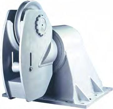


186 Specially Engineered Products Flexi Weight Block 300 Ton Block Motorized Block Fairleader 183


187 250T Equalizer Divided Block 15Ton 650T Eye and Eye Swivel 184
188

189 Gunnebo Industrier AB Tel: Gunnebo Johnson Corp. Tel: Sales Offices Gunnebo Industries Pty Ltd, AUSTRALIA Tel: general.info@gunneboindustries.com.au Gunnebo Industries Co. LTD, P.R of CHINA Tel: info@gunnebolifting.cn Gunnebo Industries GmbH, GERMANY Tel: info@gunneboindustries.de Gunnebo Anja Industrier AS, NORWAY Tel: sales@gunneboindustrier.no Gunnebo Johnson, NORTH AMERICA Tel: sales@gjcorp.com Gunnebo Industries Sp. z o.o, POLAND Tel: zawiesia@gunneboindustries.pl Gunnebo Industries (Pty) Ltd, SOUTH AFRICA Tel: info@gunnebolifting.co.za Gunnebo Industries Ltda, SOUTH AMERICA Tel: vendas@gunneboindustries.com.br Gunnebo Industrier AB, SWEDEN Tel: gbg@gunnebolifting.com Gunnebo Industries Ltd, UNITED KINGDOM Tel: sales@gunneboindustries.com Part No MG 01/15
McKISSICK BLOCKS TACKLE BLOCK & SHEAVE ASSEMBLY
 TACKLE BLOCK SHEAVE ASSEMBLY WARNINGS, USE AND MAINTENANCE INFORMATION WARNING A potential hazard exists when lifting or dragging heavy loads with tackle block assemblies. Failure to design and use tackle
Tackle Block and Sheave Assembly Warning, Use & Maintenance Information WARNING
 Tackle Block and Sheave Assembly Warning, Use & Maintenance Information WARNING A potential hazard exists when lifting or dragging heavy loads with tackle block assemblies. Failure to design and use tackle
Johnson Price Guide by Gunnebo Lifting Effective May 1, 2012
 Johnson Price Guide by Gunnebo Lifting Effective May 1, 2012 P r i c e G u i d e CONTENTS PAGE Introduction.............................................................. 1 Crane Blocks.............................................................
Tackle Block and Sheave Assembly Warning, Use & Maintenance Information WARNING
 Tackle Block and Sheave Assembly Warning, Use & Maintenance Information WARNING A potential hazard exists when lifting or dragging heavy loads with tackle block assemblies. Failure to design and use tackle
WARNING. General Cautions or Warnings. Tackle Block and Sheave Assembly Warning, Use & Maintenance Information. Definitions.
 Understanding: The Crosby Group Product Warnings (ev. 9/16/02) 43 Tackle Block and Sheave Assembly Warning, Use & Maintenance Information WARNING A potential hazard exists when lifting or dragging heavy
JOHNSON SNATCH BLOCKS BLOCKS FOR CONSTRUCTION, OILFIELD, AND TOWING
 JOHNSON SNATCH BLOCKS BLOCKS FOR CONSTRUCTION, OILFIELD, AND TOWING Single Johnson Snatch Blocks 2 30 METRIC TONS WLL SINGLE SHEAVE W/SHACKLE SINGLE SHEAVE W/HOOK & OPTIONAL LATCH SINGLE SHEAVE TAILBOARD
When buying Crosby you re buying more than product, you re buying Quality.
 From a 2 ton capacity snatch to a 6000 metric ton capacity crane, McKissick can make a McKissick s major involvement in the block McKissick When buying Crosby you re buying more than product, you re buying
JOHNSON SNATCH BLOCKS BLOCKS FOR CONSTRUCTION, OILFIELD, AND TOWING
 JOHNSON SNATCH BLOCKS BLOCKS FOR CONSTRUCTION, OILFIELD, AND TOWING Single Sheave Johnson Snatch Blocks 2 30 METRIC TONS WLL W/SHACKLE W/HOOK & OPTIONAL LATCH TAILBOARD W.L.L (METRIC TON) SWIVEL HOOK W/LATCH
Johnson Products. Crane Blocks Snatch Blocks Oilfield Blocks Swivels Custom Engineered Products
 Crane locks Snatch locks Oilfield locks Swivels Custom Engineered Products Snatch locks 6:2-6:5 Manhandler Snatch lock 6:5 Derrick lock, Galvanized 6:5 Oilfield locks 6:6-6:7 Swivels 6:8-6:11 Overhaul
Ratcheting Pullers Reversible Puller Combination Pullers Slide Hammer Pullers Heavy Duty C-Clamps...
 C L A M P I N G & P U L L I N G Ratcheting Pullers... 1137 Reversible Puller... 1139 Combination Pullers... 1139 Slide Hammer Pullers... 1139 Heavy Duty C-Clamps... 1141 General Service C-Clamps... 1142
Provided by: Operating, Maintenance & Parts Manual
 Provided by: www.hoistsdirect.com TB681.qxd 11/29/2004 3:04 PM Page 1 Operating, Maintenance & Parts Manual TB603 Manually Lever Operated Chain Hoist 1100 POUNDS MAXIMUM CAPACITY (500 kg) Follow all instructions
Engineer The Lift!! HOIST RINGS. Applied Load Changes With Sling Angle. Sample Calculation: DO S DON TS
 H&O DIE SUPPLY, INC. 1-800-222-5441 sales@hodie.com HOIST RINGS 10 Adjustable Alloy Chain Sling... 10.16 Center Pull Style... 10.4-10.5 Envirolox Protective Finish... 10.11 Eye Bolts... 10.15 Eye Nuts...
OPERATIONS MANUAL LEVER CHAIN HOIST
 OPERATIONS MANUAL LEVER CHAIN HOIST IMPORTANT SAFETY INFORMATION Please read, understand and follow all safety information contained in these instructions prior to the use of this hoist. Retain these instructions
BELOW-THE-HOOK & MATERIAL HANDLING EQUIPMENT
 BELOW-THE-HOOK & MATERIAL HANDLING EQUIPMENT lifting EQUIPMENT HRLB ROLL LIFTING BEAM...Page 44 HMRL MOTORIZED ROLL LIFTER...Page 45 HRGT ROLL GRIPPING TONGS...Page 46 HRLCH ROLL LIFTING C-HOOK...Page
00000 Series Clevis Pin Slotted Hexagon Hex Key Recommended Corresponding Part No. Part No. Size Torque Preload SLT* SLT* HEX
 00000 Series Clevis Pin All clevis pins are manufactured from heat treated 416 stainless steel to provide superior strength and wear. Hardness is between 37-40 Rc. The DCD Clevis Pin is a shouldered type
WIRE AND WIRE ROPE DIVISION
 WIRE AND WIRE ROPE DIVISION Pulley & Sheave Product Catalog www.loosco.com Pulleys and 1 V0117 Table of Contents About this catalog...3 Military Specification Technical Information...4 Military Specification
PAGE 1 OF 5 HEALTH, SAFETY & ENVIRONMENTAL MANUAL PROCEDURE: S360 Overhead Cranes & Lifts Procedure REV 4.0 8/14/2012
 PAGE 1 OF 5 PURPOSE: OVERHEAD CRANES AND LIFTS PROCEDURE The purpose of this procedure is to define the safety and training requirements for use of overhead cranes and lifts. Procedure: Definitions Designated
Before equipment use, please read this operation manual carefully. Serial Number: Date Purchased:
 Pushed & Geared Trolleys OPERATION MANUAL This operation manual is intended as an instruction manual for trained personnel who are in charge of installation, maintenance, repair etc. Before equipment use,
BELOW-THE-HOOK & MATERIAL HANDLING EQUIPMENT
 BELOW-THE-HOOK & MATERIAL HANDLING EQUIPMENT lifting EQUIPMENT Tongs HBTF Bar Tong Fixed... Page 62 TONGS HBTA Bar Tong Adjustable... Page 63 lifting EQUIPMENT HBTF BAR TONG FIXED FEATURES This style of
TONS. Before each shift: Before operating: Before initial operation of hoist:
 LEVER HOIST 0.25 9 TONS Manual Notice It is the responsibility of the owner/user to install, inspect, test, maintain, and operate these lever hoists in accordance with ASME B30.21, Safety Standard for
Marine Blocks. Copyright 2002 The Crosby Group, Inc. 315 All Rights Reserved
 Marine s s kc o l B e n i r a M Marine s Copyright 2002 The Crosby Group, Inc. 315 Western Lead s s k c o l B d a e L n r e t s e W Horizontal Lead s Available painted or galvanized. Fitted with steel
BVM Corporation TYPE MS TONG 6,500 FT/LBS. TORQUE
 Page 1 BVM Corporation TYPE MS TONG 6,500 FT/LBS. TORQUE Part number: Serial Number: BVM CORPORTION TYPE MS TONG 6,500 FT/LBS. TORQUE WRNING: Manual tongs which have experienced excessive wear or are found
using Class 2-C (Centralizing) tolerances. Jack lift shaft lead tolerance is approximately 0.004" per foot.
 tolerances. Jack lift shaft lead tolerance is approximately 0.004 per foot.") WORM GEAR JACK MODELS WORM GEAR ACTIONJAC JACKS Jack systems are ruggedly designed and produced in standard models with load handling capacities from 1/4 ton to 100 tons. They may be used individually
WORM GEAR JACK MODELS WORM GEAR ACTIONJAC JACKS Jack systems are ruggedly designed and produced in standard models with load handling capacities from 1/4 ton to 100 tons. They may be used individually
Below the Hook Lifting
 SECTION INDEX S E C T I O N 1 3 BALE LIFTING TONG...-14 BARRIER GRABS...- 14 BEAM TONGS...-14 BEAM, SPREADER Adjustable...-4 Custom...-5 Fiberglass...-4 Fixed...-3 BEAMS, LIFTING Adjustable Hook...-1 Custom...-5
CHAIN & HOOKS. Proof Coil Chain Grade 28. Transport Chain Grade 70
 Proof Coil Chain Grade 28 Proof coil chain is suitable for use as towing chain, logging,fencing, trailer safety chain, boat anchors, security barriers or other general purposes where chain of high tensile
Model 580 / 580J Coupling
 MANUFACTURING CO. THE FIRST NAME IN QUALITY COUPLINGS Installation, Inspection, Operation & Maintenance Guide Model 580 / 580J Coupling IMPORTANT Read these instructions completely before installing, using
Model 6 Weld-On Drawbar Eye
 MANUFACTURING CO. THE FIRST NAME IN QUALITY COUPLINGS Installation, Inspection, Operation & Maintenance Guide Model 6 Weld-On Drawbar Eye IMPORTANT Read these instructions completely before installing,
For more than 25 years
 For more than 25 years More performance. More options. More value. We can move it! No matter how much, how fast or how far you need to lift, pull or position, our promise to you is very simple: WE CAN
HOISTS RATCHET LEVER HOISTS
 Yale HOISTS RATCHET LEVER HOISTS Yale PE & RS Ratchet Lever Hoist / to ton capacities Link chain models Light and portable Weatherized load brake Requires less handle pull to lift full load Efficient Yale
Model 320 / 320A Hinge Assembly
 MANUFACTURING CO. THE FIRST NAME IN QUALITY COUPLINGS Installation, Inspection, Operation & Maintenance Guide Model 320 / 320A Hinge Assembly IMPORTANT Read these instructions completely before installing,
Lineman s Hoist. Operating, Maintenance & Parts Manual. Follow all instructions and warnings for LMST680-2
 Lineman s Hoist LMST0- Operating, Maintenance & Parts Manual Lineman s Hoist Follow all instructions and warnings for inspecting, maintaining and operating this hoist. The use of any hoist presents some
SPECIFICATIONS GENERAL SAFETY RULES PERSONAL SAFETY. Save This Manual TOOL USE AND CARE WORK AREA
 SPECIFICATIONS 2 Forged Safety Latch Hooks Cable extends to: 44 Drop forged steel hanging bracket Heavy duty 3/16 Steel Cable Pulling Capacity: 1200 LB. One piece double ratchet gear Save This Manual You
Health & Safety Policy and Procedures Manual SECTION 22 CRANE SUSPENDED PERSONNEL PLATFORMS
 SECTION 22 CRANE SUSPENDED PERSONNEL PLATFORMS 1. Scope: This policy and procedure applies to the design, construction testing, use, and maintenance or personnel platforms and hosting of personnel platforms
Cranes. Range Diagram and Lifting Capacity RT345-1XL 45 TON LIFTING CAPACITY RANGE DIAGRAM 33.75' - 105' BOOM
 Range Diagram and Lifting Capacity RT345-1XL Cranes 45 TON LIFTING CAPACITY RANGE DIAGRAM 33.75' - 105' BOOM DIMENSIONS ARE FOR LARGEST FACTORY FURNISHED HOOK BLOCK AND HOOK & BALL, WITH ANTI-TWO BLOCK
Cranes. Range Diagram and Lifting Capacity RT TON LIFTING CAPACITY RANGE DIAGRAM 40' - 126'
 Range Diagram and Lifting Capacity Cranes 80 TON LIFTING CAPACITY RANGE DIAGRAM 40' - 126' BOOM Dimensions are for largest factory furnished hook block and hook & ball, with anti-two block activated COUNTER
Owner s Manual: PS SERIES WINCHES
 Owner s Manual: PS SERIES WINCHES PIERCE ARROW INC. 549 U.S. HWY 287 S. HENRIETTA, TEXAS 76365 -------------------------------------------------------- TOLL FREE 800-658-6301 FAX 940-538-4382 --------------------------------------------------------
40' ' POWERED BOOM: MODE 1 40' - 126' POWERED BOOM: MODE 2
 Range Diagram and Lifting Capacity Cranes 100 TON LIFTING CAPACITY 40' - 97.3' POWERED BOOM: MODE 1 40' - 126' POWERED BOOM: MODE 2 CRANE WORKING CONDITIONS DIMENSIONS ARE FOR LARGEST FACTORY FUR- NISHED
Cranes. Range Diagram and Lifting Capacity RT TON LIFTING CAPACITY RANGE DIAGRAM 33' - 110' BOOM
 Range Diagram and Lifting Capacity Cranes 55 TON LIFTING CAPACITY RANGE DIAGRAM 33' - 110' BOOM Dimensions are for largest factory furnished hook block and hook & ball, with anti-two block activated COUNTER
Lifting Capacities Telescopic Boom All Terrain Crane ATC ton (118 metric ton) Link Belt
 Link Belt") Lifting Capacities Telescopic Boom All Terrain Crane ATC 3130 130 ton (118 metric ton) Boom and fly capacities for this machine are listed by the following sections: Fully Extended Outriggers Working Range
Lifting Capacities Telescopic Boom All Terrain Crane ATC 3130 130 ton (118 metric ton) Boom and fly capacities for this machine are listed by the following sections: Fully Extended Outriggers Working Range
LINK-BELT MODEL HTC TON CAPACITY RANGE DIAGRAM. LIFTING CHARTS - Hydraulic Truck Cranes
 LIFTING CHARTS - Hydraulic Truck Cranes LINK-BELT MODEL HTC-840-40 TON CAPACITY RANGE DIAGRAM NOTE: and fly and jib geometry shown are for unloaded condition and machine standing level on firm supporting
COLUMBUS McKINNON CORPORATION
 COLUMBUS McKINNON CORPORATION INNOVATIVE ENGINEERING DESIGNED FOR YOU To create the best ratchet lever hoist on the market, Columbus McKinnon started with a fundamental question how do people use ratchet
The HKK Solid Advantage
 The HKK Solid Advantage HKK Chain, with its cold-forged, solid bushings, solid rollers, and specially treated pins and bushings provides a unique advantage over conventional chains. HKK s cold forging
Model 407SE Swivel Drawbar Eye
 MANUFACTURING CO. THE FIRST NAME IN QUALITY COUPLINGS Installation, Inspection, Operation & Maintenance Guide Model 407SE Swivel Drawbar Eye IMPORTANT Read these instructions completely before installing,
Planning Advisory Notice
 Capstan hoists, often referred to as catheads, make back-breaking work faster, easier and more productive. They are used for many applications in multiple industries including telecommunications, electric
Recovery Winch Owner s Manual 1
 Recovery Winch Owner s Manual 1 2 Pierce Arrow 800-658-6301 Recovery Winch Owner s Manual The PS series winch is a powerful tool and must be used with extreme care. Deviating from the manual s instructions
Range Diagram and Lifting Capacity T Cranes RANGE DIAGRAM BOOM
 Range Diagram and Lifting Capacity T340-1 Cranes RANGE DIAGRAM 30-94 BOOM Dimensions are for largest factory furnished hook block and hook & ball, with anti-two block activated COUNTER WEIGHT BOOM LENGTH
580RK SERVICE GUIDELINES For coupling models: 580 & 580J
 580 Coupling THE FIRST NAME IN QUALITY COUPLINGS 580RK SERVICE GUIDELINES For coupling models: 580 & 580J BEFORE GETTING STARTED: This procedure should only be performed by a qualified mechanic. Measure
CHESTER HOIST AIR LOW HEADROOM CHAIN HOISTS AL-680 SECTION A
 CHESTER HOIST AIR LOW HEADROOM CHAIN HOISTS AL-680 SECTION A OPERATING and MAINTENANCE INSTRUCTIONS FOR AL SERIES HOISTS Users should refer to the ANSI B30.16 American National Standard and ASME HST-5M
Quality Rigging Products. / / Phone:
 Quality Rigging Products www.associatedwirerope.com / sales@awrrinc.com / Phone: 310.448.5444 The Company Pg. 04 General Cautions or Warnings Pg. 05 product certification Quality Control & Manufacturing
LS 278H. 250 ton (227 metric ton) Hydraulic Lattice Boom Crawler Crane. Tube Boom Capacities ft. ( m)
 Hydraulic Lattice Boom Crawler Crane. Tube Boom Capacities ft. ( m)") Hydraulic Lattice Crawler Crane Tube Capacities 60 330 ft. (18.29 100.58 m) 250 ton (227 metric ton) 35 ft. (10.67 m) Live Mast Capacities On Outrigger Jacks On Side Frames 10 ft. (3.05 m) Extension Lifting
Hydraulic Lattice Crawler Crane Tube Capacities 60 330 ft. (18.29 100.58 m) 250 ton (227 metric ton) 35 ft. (10.67 m) Live Mast Capacities On Outrigger Jacks On Side Frames 10 ft. (3.05 m) Extension Lifting
Capacity (tonnes) 0.25t. No. of Falls 1. Load Chain (mm) Load Chain Grade 80
 0.25t. No. of Falls 1. Load Chain (mm) Load Chain Grade 80") Capacity (tonnes) Model NO. 0.25t K025 No. of Falls Load Chain (mm) 4 2 Load Chain Grade 80 Pull To Lift Rated Load (N) Test load (tonnes) Hand Chain (mm) Std. lift (ft) Net. Weight (lbs) Gross. Weight
Capacity (tonnes) Model NO. 0.25t K025 No. of Falls Load Chain (mm) 4 2 Load Chain Grade 80 Pull To Lift Rated Load (N) Test load (tonnes) Hand Chain (mm) Std. lift (ft) Net. Weight (lbs) Gross. Weight
Technical Manual. Inspection Record For: Hoist Model No.: Hoist Serial No.: Hoist Inspection and Maintenance Guide
 CPTEN-136 Technical Manual Hoist Inspection and Maintenance Guide Inspection Record For: Hoist Model No.: Hoist Serial No.: WARNING! Failure to follow these inspection procedures can cause personal injury
1 Clearheart Construction Co., Inc. Mobile Crane - Onshore MOBILE CRANES Cranes and derricks
 Mobile Crane - Onshore MOBILE CRANES Cranes and derricks. - 1926.550 Cranes, like all pieces of heavy equipment, if not properly operated, inspected and maintained have a potential for causing major bodily
Convertible - Rated 3 4-Ton /2-Ton Nylon Strap Hoists Refer to any questions about the use, application, repair or testing of this hoist to:
 Operating and Servicing Instructions for Convertible - Rated 3 4-Ton - 1 1 /2-Ton Nylon Strap Hoists Refer to any questions about the use, application, repair or testing of this hoist to: Hubbell / Chance
Chapter 11 Rolling Contact Bearings
 Chapter 11 Rolling Contact Bearings 1 2 Chapter Outline Bearing Types Bearing Life Bearing Load Life at Rated Reliability Bearing Survival: Reliability versus Life Relating Load, Life, and Reliability
CRANE RATING MANUAL HTC
 SERIAL NUMBER: XXXX- XXXX CRANE RATING MANUAL HTC- 8611 TELESCOPIC BOOM TRUCK CRANE - 164.1 SIX SECTION LATCHING BOOM For Replacement, Order Part Number: T2P38 (116) R Link-Belt is a registered trademark.
INSTRUCTION MANUAL. Pacific Self-locking Beam Trolleys Pacific Adjustable Angle Clamps Pacific Top Girder Clamps
 INSTRUCTION MANUAL Pacific Self-locking Beam Trolleys Pacific Adjustable Angle Clamps Pacific Top Girder Clamps IMPORTANT Please read this instruction manual before using these products. This manual contains
Grade 80 & 100 Alloy Chain
 Grade 80 & 100 Alloy Chain General Information WORKING LOAD LIMIT The Working Load Limit is the maximum load in pounds which should ever be applied to chain, when the chain is new or in as-new condition,
Owner s Manual: PS4000 4,000 LB. WINCH
 Owner s Manual: PS4000 4,000 LB. WINCH PIERCE ARROW INC. 549 U.S. HWY 287 S. HENRIETTA, TEXAS 76365 ---------------------------------------------------- TOLL FREE 800-658-6301 FAX 940-538-4382 ----------------------------------------------------
Wallace Tri-Adjustable Gantry Cranes Square Tube Assembly Instructions
 Wallace Tri-Adjustable Gantry Cranes Square Tube Assembly Instructions For any additional information, Please call 1- S 1. Read and understand instructions before using this gantry. 2. Inspect gantry thoroughly
MINING PRODUCTS FOR HOISTS & RIGGING. Manual Hoists. Chain & Rigging Attachments. Specialized Attachments. Liner Bolts. for THE MINING INDUSTRY
 A Complete Line of Products & Solutions for THE MINING INDUSTRY HOISTS & RIGGING PRODUCTS FOR MINING Manual Hoists Chain & Rigging Attachments Specialized Attachments Liner Bolts Columbus McKinnon Family
Model 240K / 240KL Coupling
 MANUFACTURING CO. THE FIRST NAME IN QUALITY COUPLINGS Installation, Inspection, Operation & Maintenance Guide Model 240K / 240KL Coupling IMPORTANT Read these instructions completely before installing,
Wire rope accessories. 5. Wire rope accessories. Index
 Wire rope accessories 5. Wire rope accessories 1 General 1.1 About Hendrik Veder Group 1.2 Trade names 1.3 Certified Quality 1.4 Certificates 1.5 Key suppliers & brands 1.6 Contact information 1.7 Locations
truck crane 140 tons link-belt htc-3140lb BOOM LENGTHS: 42 to 195 ft JIB LENGTHS: 38 to 109 ft JIB OFFSETS:
 truck crane 140 tons link-belt htc-3140lb BOOM LENGTHS: 42 to 195 ft JIB LENGTHS: 38 to 109 ft JIB OFFSETS: 2-15 - 30-45 NOTES: Technical Data Specifications & Capacities Telescopic Boom Truck Crane 140
COLUMBUS McKINNON CORPORATION
 COLUMBUS McKINNON CORPORATION INNOVATIVE ENGINEERING DESIGNED FOR YOU To create the best ratchet lever hoist on the market, Columbus McKinnon started with a fundamental question how do people use ratchet
RENFROE. WARNING: Before putting tool in service, take to your immediate supervisor.
 WARNING: Before putting tool in service, take to your immediate supervisor. RENFROE Model NM Clamp Application, Operation and Maintenance Manual OM 211-NM Operators Manual This Operator s Manual covers
1000-lb Hydraulic Truck Crane
 1000-lb Hydraulic Truck Crane Owner s Manual WARNING: Read carefully and understand all ASSEMBLY AND OPERATION INSTRUCTIONS before operating. Failure to follow the safety rules and other basic safety precautions
Range Diagram and Lifting Capacity RT230. Cranes 30 TON LIFTING CAPACITY RANGE DIAGRAM 30' - 94' BOOM REDUCTION IN MAIN BOOM CAPACITY
 Range Diagram and Lifting Capacity Cranes 30 TON LIFTING CAPACITY RANGE DIAGRAM 30' - 94' BOOM Dimensions are for largest factory furnished hook block and hook & ball, with anti-two block activated COUNTER
Cranes. OSHA Office of Training & Education 1
 Cranes OSHA Office of Training & Education 1 Major Causes of Crane Accidents Contact with power lines Overturns Falls Mechanical failures OSHA Office of Training & Education 2 How Do Accidents Occur? Instability
Range Diagram and Lifting Capacity T Cranes. View thousands of Crane Specifications on FreeCraneSpecs.com RANGE DIAGRAM BOOM
 Range Diagram and Lifting Capacity Cranes RANGE DIAGRAM 30-94 BOOM Dimensions are for largest factory furnished hook block and hook & ball, with anti-two block activated COUNTER WEIGHT BOOM LENGTH UPPERSTRUCTURE
Hand Chain Hoists. Before equipment use, please read this operation manual carefully. Serial Number: Date Purchased:
 Hand Chain Hoists OPERATION MANUAL This operation manual is intended as an instruction manual for trained personnel who are in charge of installation, maintenance, repair etc. Before equipment use, please
Please make your selections below to view, search or print ACCO Material Handling Solutions WRIGHT SPEEDWAY and WRIGHT WORK-RATED product pages.
 Contact Information Welcome! Please make your selections below to view, search or print ACCO Material Handling Solutions WRIGHT SPEEDWAY and WRIGHT WORK-RATED product pages. 1T to 5T THE NEW CENTURY SERIES
RTC 8050 Series II. 50 ton (45.36 metric tons) Telescopic Boom Rough Terrain Crane
 Telescopic Boom Rough Terrain Crane") Telescopic Boom Rough Terrain Crane RTC 85 Series II 5 ton (45.36 metric tons) Boom and Fly Capacities for this machine are listed by the following sections. Working Range Diagram 35.5 to 6.3 (1.82 18.38
Telescopic Boom Rough Terrain Crane RTC 85 Series II 5 ton (45.36 metric tons) Boom and Fly Capacities for this machine are listed by the following sections. Working Range Diagram 35.5 to 6.3 (1.82 18.38
Design of Components used in Hoisting Mechanism of an EOT Crane: A Critical Literature Review
 Design of Components used in Hoisting Mechanism of an EOT Crane: A Critical Literature Review Mr. Swapnil K. Agrawal Department of Mechanical Engineering Vidarbha Institute of Technology, Nagpur, India
Range Diagram and Lifting Capacity RT665. Cranes 65 TON LIFTING CAPACITY RANGE DIAGRAM 36' - 111' BOOM REDUCTION IN MAIN BOOM CAPACITY
 Range Diagram and Lifting Capacity Cranes 65 TON LIFTING CAPACITY RANGE DIAGRAM 36' - 111' BOOM DIMENSIONS ARE FOR LARGEST FACTORY FURNISHED HOOK BLOCK AND HOOK & BALL, WITH ANTI-TWO BLOCK ACTIVATED COUNTER
T 775. truck crane 75 ton capacity. range diagram & lifting capacities. Range Diagram (40' - 126' boom)
") T 7 truck crane ton capacity range diagram & lifting capacities DEFLECTIONS NOT SHOWN 6' - 9" 4' - 8" DIMENSIONS ARE FOR LARGEST FACTORY FURNISHED HOOK BLOCK AND HOOK & BALL, WITH ANTI-TWO BLOCK ACTIVATED
T 7 truck crane ton capacity range diagram & lifting capacities DEFLECTIONS NOT SHOWN 6' - 9" 4' - 8" DIMENSIONS ARE FOR LARGEST FACTORY FURNISHED HOOK BLOCK AND HOOK & BALL, WITH ANTI-TWO BLOCK ACTIVATED
COLUMBUS McKINNON CORPORATION
 COLUMBUS McKINNON CORPORATION INNOVATIVE ENGINEERING DESIGNED FOR YOU To create the best ratchet lever hoist on the market, Columbus McKinnon started with a fundamental question how do people use ratchet
LINK-BELT MODEL HTC-8675LB - 75 TON CAPACITY 48 7" (.80m) 41 0" /8" (3.52m) /16" (2.02m) /4" (.34m) 25" 11 0" (.
 41 0 /8 (3.52m) /16 (2.02m) /4 (.34m) 25 11 0 (.") LIFTING CHARTS - Hydraulic Truck Cranes LINK-BELT MODEL - 75 TON CAPACITY 41 0" (12.50m) 48 7" (14.80m) C L Of Rotation 13 8 1/8" (4.17m) 7 0" (2.13m) 4 5/8" (118mm) 11 6 7/8" (3.52m) 6 7 11/16" (2.02m)
LIFTING CHARTS - Hydraulic Truck Cranes LINK-BELT MODEL - 75 TON CAPACITY 41 0" (12.50m) 48 7" (14.80m) C L Of Rotation 13 8 1/8" (4.17m) 7 0" (2.13m) 4 5/8" (118mm) 11 6 7/8" (3.52m) 6 7 11/16" (2.02m)
America s Largest Importer/Wholesaler of Wire Rope, Chain and Fittings!
 America s Largest Importer/Wholesaler of Wire Rope, Chain and Fittings BLOCKS BINDERS Failure to design and use tackle block systems properly may cause a load to slip or fall - the result could be serious
BUNTING BEARINGS LLC
 BUNTING BEARINGS LLC Product Catalog Certified to ISO 9001 CAST BRONZE BEARINGS CONTINUOUS AND CENTRIFUGAL CAST BRONZE BAR AND WEARPLATE POWDERED METAL PRODUCTS CUSTOM MACHINED PRODUCTS LUBE-ALIGN MOUNTED
Model 240K / 240KL Coupling
 MANUFACTURING CO. THE FIRST NAME IN QUALITY COUPLINGS Installation, Inspection, Operation & Maintenance Guide Model 240K / 240KL Coupling IMPORTANT Read these instructions completely before installing,
SBRL-SERIES SPREADER BEAMS INSTRUCTION MANUAL
 VESTIL MANUFACTURING CORP. 2999 North Wayne Street, P.O. Box 507, Angola, IN 46703 Telephone: (260) 665-7586 -or- Toll Free (800) 348-0868 Fax: (260) 665-1339 www.vestilmfg.com e-mail: info@vestil.com
Model 470 / 470H Coupling
 MANUFACTURING CO. THE FIRST NAME IN QUALITY COUPLINGS Installation, Inspection, Operation & Maintenance Guide 470 470H Model 470 / 470H Coupling IMPORTANT Read these instructions completely before installing,
Distributed by Tri-State Equipment Company Inc. Web: PH: FAX:
 Lineman s Hoist Distributed by Tri-State Equipment Company Inc. Email: sales@tsoverheadcrane.com Web: www.tsoverheadcrane.com PH: -869-00 FAX: -869-6 LMST680 Operating, Maintenance & Parts Manual Lineman
CRANE RATING MANUAL HTC
 SERIAL NUMBER: CRANE RATING MANUAL 5---Section Boom For Replacement, Order Part Number: N3P0199 (031907) R Link-Belt is a registered trademark. 1of244 N3P0200 Table Of Contents Page Contents 3---4 Operating
TABLE OF CONTENTS DESCRIPTION. Safety Instructions & Safety Sign Locations Operating Instructions Assembly Instructions...
 TABLE OF CONTENTS DESCRIPTION PAGE Warranty... 1 Safety Instructions & Safety Sign Locations... 2 Operating Instructions... 3 Assembly Instructions... 5 500 & 600 Snowblower Drawings... 8 500 & 600 Snowblower
Yale HOISTS. 414 West Broadway Ave. P.O. Box 769 Muskegon, MI PH: FX:
 Yale HOISTS! To Avoid Injury: Do not exceed working load limit, load rating, or capacity. Do not use to lift people or loads over people. Read and follow all instructions. 44 West Broadway Ave. P.O. Box
SIDE-WIND, A-FRAME TRAILER JACK. Model Due to continuing improvements, actual product may differ slightly from the product described herein.
 SIDE-WIND, A-FRAME TRAILER JACK Model 95157 Assembly And Operation Instructions Due to continuing improvements, actual product may differ slightly from the product described herein. 3491 Mission Oaks Blvd.,
1250 LB. CAPACITY MECHANICAL WHEEL DOLLY
 1250 LB. CAPACITY MECHANICAL WHEEL DOLLY 67287 SET-UP AND OPERATING INSTRUCTIONS Visit our website at: http://www.harborfreight.com Read this material before using this product. Failure to do so can result
Lincoln Hoist. Web Hoist Operating Manual. Lincoln Hoist
 Lincoln Hoist Web Hoist Operating Manual Lincoln Hoist Mfg. by Lincoln Precision Machining Company 121 Creeper Hill Road, P.O. Box 458, North Grafton, MA 01536 USA Toll Free (888) 306-7222 Phone (774)
Owner s Manual. ELECTRIC WIRE ROPE HOIST and TROLLEY RH SERIES
 EFFECTIVE: September 25, 2007 Owner s Manual ELECTRIC WIRE ROPE HOIST and TROLLEY RH SERIES 2 Ton through 20 Ton Capacity Product Code and Serial Number WARNING This equipment should not be installed,
Synchronous Belt Failure Analysis Guide
 Synchronous Belt Failure Analysis Guide Contents Part 1: Common Causes of Belt Failure Normal Belt Wear and Failure Belt Crimp Failures Shock Load Part 2: Improper Belt Installation Tension Introduction
Model 580 / 580J Coupling
 MANUFACTURING CO. THE FIRST NAME IN QUALITY COUPLINGS Installation, Inspection, Operation & Maintenance Guide Model 580 / 580J Coupling IMPORTANT Read these instructions completely before installing, using
LIFTING MAGNET OPERATING, MAINTENANCE, & PARTS MANUAL
 LIFTING MAGNET OPERATING, MAINTENANCE, & PARTS MANUAL ACI Hoist & Crane 757 Southeast 17 th Street Fort Lauderdale, Fl 33116 Phone: 954-367-7116 Fax: 954-272-0334 www.acihoist.com Table of Contents SECTION
Series 1300 Hydraulic Crane 30 Ton Load Ratings
 Series 13 Hydraulic Crane Ton Load Ratings! DANGER AN UNTRAINED OPERATOR SUBJECTS HIMSELF AND OTHERS TO DEATH OR SERIOUS INJURY YOU MUST NOT OPERATE THIS CRANE UNLESS You have been trained in the safe
In This Document MODULE DESCRIPTION This module provides information on the safety concerns and
 Crane Safety Fact Sheet In This Document MODULE DESCRIPTION This module provides information on the safety concerns and Introduction necessary precautions you will need to be aware of when working Crane
U.S. TSUBAKI DRIVE CHAINS
 DRIVE CHAINS Contents Page ANSI RS ROLLER CHAIN A- ~ A-4 INTRODUCTION A- ~ A-5 RS5 THROUGH RS4 A-6 ~ A-9 HEAVY SERIES A- RS DOUBLE PITCH ROLLER CHAINS A- SELECTION AND ENGINEERING INFORMATION A- ~ A-4
RENFROE. WARNING: Before putting tool in service, take to your immediate supervisor. Model SCSL Clamp Application, Operation and Maintenance Manual
 WARNING: Before putting tool in service, take to your immediate supervisor. RENFROE Model SCSL Clamp Application, Operation and Maintenance Manual OM 311 SCSL Operators Manual This Operator s Manual covers
Heavy-Duty Rod Ends - Male with integral spherical plain bearing
 Heavy-Duty Rod Ends - Male with integral spherical plain bearing 65700 Order No. Thread (hand) d 1 l 1 d 2 d 3 d 4 l 2 l 3 X g H7 65700.W0005 Right 5 33 M 5 11,11 18 20 9 14 65700.W0006 Right 6 36 M 6
Polyester Lifting Slings
 Est. 969 Polyester Lifting Slings FASTLIFT Endless Roundsling (ERS) Roundslings with seamless single cover and protected label WLL Colour Weight Rec. min Rec. min Standard size range available (tonnes)