Assembly Instructions
|
|
|
- Miles Hodge
- 5 years ago
- Views:
Transcription

1 Assembly Instructions Revision 4: 2016
2 TABLE OF CONTENTS Important Information 5 Warranty 5 Limit of Liability 5 For Your Records 5 Operation 5 Maintenance 6 When Your Shipment Arrives 6 Tools & Personnel Required 6 Conveyor Assembly 7 Leg Supports 8 Low Rider Caster Supports 8 Peg Leg Supports 8 Upright Leg Supports Wide H Base Leg Supports Wide T Base Leg Supports 9 Radius Turn Legs 11 Leg Straps 11 Belt Installation 13 Removing the Feed End 13 Standard Feed End 13 Heavy Duty Feed End 13 Inserting the Belt 14 Standard Belting 14 Belting with Hold Down Tabs 14 Radius Turn Belting 15 2
3 Lacing the Belt 16 Removing the Lacing Rod 16 Standard Belting & Abrasion Resistant Lacing Rods 16 Radius Turn Lacing Rod 16 Re-installing the Lacing Rod 17 Standard Belting Lacing Rod 17 Abrasion Resistant Lacing Rod 17 Radius Turn Lacing Rod 17 Belt Break In 18 Replacing the Feed End 18 Standard Feed End 18 Heavy Duty Feed End 19 3

4 IMPORTANT The information contained in this manual is provided only as an aid and service to our customers. Dynamic Conveyor Corporation does not warrant the accuracy or applicability of such information and is not specifically responsible for property damage and/or personal injury inflicted directly or indirectly, or for damages and/or failures caused by improper application, installation, operation, abuse and/or misuse of its products whether or not based on information contained herein. WARRANTY Dynamic Conveyor Corporation warrantees products of its own manufacture for a period of five (5) years on the DynaCon product line. Dynamic Conveyor Corporation will repair or replace any products that have failed under normal use due to faulty material or defective workmanship. Components, products and conveyors not manufactured by Dynamic Conveyor will be covered by the manufacturer s warranty. No other warranty is expressed or implied unless otherwise set forth in writing and approved by representative duly authorized to extend such approval by Dynamic Conveyor Corporation. Additional note: Any Dynamic Conveyor Corporation equipment/systems that are physically altered without direct authorization from Dynamic Conveyor Corporation shall be termed Product altered without authorization: no warranty or liability applies to that altered equipment/system. LIMIT OF LIABILITY In no event shall Dynamic Conveyor Corporation be liable for any special, indirect, incidental, or consequential damages of any character, including but not limited to loss of production facilities or equipment, lost profits, property damage, lost production, or any consequential downtime, whether suffered by distributor or third party, irrespective of whether claims or actions for such damages are based upon contract, warranty, tort (including negligence), strict liability, or otherwise. FOR YOUR RECORDS Thank you for your investment in a DynaCon Conveyor. We believe our product will become a vital step in your production process and it will grow with your changing needs. Please take the time to complete the following information as thoroughly as possible. It will prove helpful when you contact customer service in the event you have any questions about assembly, installation or operation. Date of Shipment: Serial Number: Model Number: DYNAMIC CONVEYOR CORPORATION 5980 Grand Haven Road Norton Shores, Michigan x 106 Service@DynamicConveyor.com Find videos and additional assembly information on our website at OPERATION DynaCon Conveyors are designed to operate continuously in a forward direction, i.e., product is conveyed toward and discharged off of the motorized module (Drive Module), with capability for occasional reversing. If your conveyor requires continuous operation in a reverse direction, please contact Dynamic Conveyor for recommendations. 4
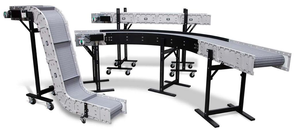
5 MAINTENANCE DynaCon Conveyors are designed to be easy to maintain and repair. To ensure proper operation, we recommend periodically inspecting the frame, motor, and belt paths for wear and damage. The drawing will look something like the picture below. Belt tensioning may be needed shortly after initial installation as the belt can stretch. Under ordinary operating conditions, the belt and conveyor frame should be checked for any abnormal wear or stress (i.e. continuous grooves, cracks, etc.). No lubrication of the belt or belt paths is necessary. Under high speed or continuous use conditions, more frequent inspection is encouraged. Under dirty or greasy operating conditions, a daily inspection along with periodic cleaning of the belt, belt paths, and belt supports is recommended. This will require removal of the belt in most cases. (Note: DynaCon Conveyors are not intended for use in abrasive environments.) Necessary steps should be taken to correct any problems as soon as they are discovered. Any questions or concerns may be directed to your local sales representative and/or our customer service department. WHEN YOUR SHIPMENT ARRIVES The packing slip will be accompanied with a drawing of your conveyor configuration. The drawing will prove helpful when assembling your conveyor. TOOLS & PERSONNEL REQUIRED Accompanying this Assembly Instructions booklet is a 7/32 Bondhus Bit for button-head cap screws. Every DynaCon Conveyor requires a minimum of two assemblers. Locate an area where you will have ample space to lay out the conveyor. Your DynaCon Conveyor configuration may differ from the following examples shown. If you have multiple conveyors shipped to you, colored dots on the inside of the modules will indicate each conveyor. Follow the step-by-step directions on the proceeding pages. 5
6 CONVEYOR ASSEMBLY Connecting Modules Lay conveyor out in sections not to exceed six (6) modules. 1 Remove extra screws for later use. 2 Loosen screws so connecting plate is free to move out slightly. 3 Align bosses on modules with connecting plate holes, and use screws from step 1 to attach. All modules will connect in this manner. Do not over-tighten connecting screws. Shimmed Module Non-Shimmed Module Some belt styles will require shimmed modules. Never connect a shimmed module to a nonshimmed module. 6
7 LEG SUPPORTS There should be one (1) leg support for every five (5) modules LOW RIDER CASTER LEG SUPPORTS PEG LEG SUPPORTS Use two provided screws to attach bracket to top and bottom bosses. Refer to configuration drawing on placement of low rider supports Peg legs come with a HRD200 (Hardware Kit) Installation of Peg Leg Supports Place washers between leg and sidewall. Choose holes on leg based on height required. Use provided screws to attach legs to sidewall. 7
8 UPRIGHT LEG SUPPORTS Crossbar Requirement by Conveyor Width & Height H Base Leg Supports for 4-10 Wide Conveyors 24 to 60 leg supports require 1 cross bar (Below) 72 to 96 leg supports require 2 cross bars 108 and taller leg supports require 3 cross bars and must be permanently secured to the floor T Base Leg Supports for Wide Conveyors 24 to 60 leg supports require 2 cross bars (Below) 72 to 96 leg supports require 3 cross bars 108 and taller leg supports require 4 cross bars and must be permanently secured to the floor Installation of Upright Leg Supports Remove center screws from all crossbar(s) 8
9 Slide crossbar(s) into track and straighten so they are perpendicular to uprights. Evenly space all crossbars making sure one (1) crossbar is at the bottom on T Base Supports. Attach all crossbars with screws from previous step. Do not attach crossbar in the way of any moving parts (e.g. belt flights) Attach black plastic spacer to designated boss. (Both Sides) Slide spacer into track of leg. Make sure to keep flanged portion between conveyor and leg support upright. Use provided screws to secure leg to sidewall through spacer. 9

10 Radius Turn Legs If your conveyor has a radius turn module, attach provided brackets with provided screws. Set the module onto the holding brackets. Attach extrusion covers to top of leg supports Installation of Leg Straps Make sure that screw in tightening knob is flush with nut and threads are not exposed. Flush Screw Non-Flush Screw 10

11 Loosely screw the leg strap to conveyor. The strap should be able to swivel around the screw. Refer to the optimum range for leg strap placement to guide you on where to place leg strap on module. OPTIMUM RANGE FOR LEG STRAPS Insert diamond flange into track. Tighten nut inside track. The flange will twist and clamp onto the leg holding it in place. Tighten the screw at the top of the strap. Cut-away views for instructional purposes 11

12 BELT INSTALLATION Removing the Feed End Standard Feed End Remove the end of the feed module by removing the (3) three screws connecting the module on each side. Heavy Duty Feed End Remove the end of the feed module by removing the last (4) four screws on the plate. 12


13 Inserting the belt Standard Belting Installation Guide belt into the top belt path. Slide belt all the way down to drive sprockets. It should take very little effort to slide the belt onto the conveyor. Belting with Hold Down Tabs Slide the tabs onto the floating belt support. (Typically this is the center belt support.) It should take very little effort to slide the belt onto the conveyor. 13
14 Radius Turn Belting Guide belt into the top belt path. The belt will only fit with the raised edge on top. When inserting the belt, make sure the arrows located on the ends of the belt are facing towards the motor. Slide belt to the drive sprockets at the end by pulling from the outside radius of the belt. Determine the larger of two tooth spaces on the radius sprockets(s). Fit the lacing rod into the larger tooth on sprocket(s). Turn the motor on once the belt has been seated correctly to the sprocket(s). Turn the motor off once it has reached the feed end. If the ends overlap, remove the necessary number of links by pulling out a lacing rod. If belt is too long, remove sections of links as needed to make belt fit snug. To do this, remove one lacing rod. Reattach removed hardware. 14
15 Lacing the Belt Once belt is at drive end, make sure the drive sprockets are properly seated in the belt. Turn on motor. If your belt has Hold Down Tabs, make sure the tabs are centered on the bottom support as well. Turn motor off once belt is near the feed end. If belt is too long, remove rows of links as needed to make belt fit snug by removing one lacing rod. Removing the Lacing Rod Standard Belting & Abrasion Resistant Lacing Rod To remove lacing rods cut off the head of lacing rod and push rod out. Radius Turn Lacing Rod Insert screwdriver on top of the belt and twist. Push rod through the hole until you can grab it and pull it the rest of the way. 15
16 Re-installing the Lacing Rod Standard Belting Join belt ends together so the hinges are aligned. Insert the rod through the hinges, leaving only the rod head protruding. Use a screwdriver to push the rod head into the belt while applying pressure down and away from the Snap-Lock. Abrasion Resistant Rod Insert white lacing rod where belt ends join. Then insert lacing rod ends by applying pressure down and away with a screwdriver. Radius Turn Belting Cut lacing rods 0.6 in (15mm) shorter than overall length. Insert rod as far as possible when belt ends join. Use a screw driver to ensure rod is fully inserted. 16
17 Belt Break In The belt can lengthen after the break-in period. To adjust for the change in belt length, remove feed end. Adjustment Holes On the spacer there are two posts that maintain the tailstock position. Make sure they are fitted into the adjustment holes on the feed plates. Loosen (do not remove) screws that connect the shaft to module. Move shaft back to take up extra belt length. Reattach removed hardware. Enlarged for clarity Replacing the Feed End Standard Feed End Reattach belt paths and feed end. The belt does not have to be excessively tight. 17

18 Heavy Duty Feed End Reattach take-up sidewall & hardware. To adjust the feed end, loosen the four (4) screws on the adjustable take up plate. Either loosen or tighten the adjustable take up screw on both sides of the conveyor. Make sure each side is tightened equally. It may help to measure the adjustable take up screws. The belt does not need to be excessively tight. 18
19 19
DynaCon Instruction Manual
 DynaCon Instruction Manual Table of Contents Technical Specification & Warranty.... 3 Construction, Benefits & Safe Operating Procedures... 4 Noise Levels... 5 Installation, Operation & Maintenance...
Food Processing Conveyor Guidelines
 Food Processing Conveyor Guidelines Revision 3: 2017 TABLE OF CONTENTS Belt Installation Plastic Link Style. 10 Belt Installation ThermoDrive... 8 Belt Removal Plastic Link Style.. 10 Belt Removal ThermoDrive.
Adjustable Angled Incline Conveyor Owners Manual with Operating Instructions
 Adjustable Angled Incline Conveyor Owners Manual with Operating Instructions Revision 012211 Table of Contents Basic Conveyor Features 3 Getting Started 4 Setting Up the Incline Conveyor 5 Belt Removal
VW Shift Paddle Kit Installation Instructions
 VW Shift Paddle Kit Installation Instructions Parts Included: (1) Left and right shift paddle (1) Small pick tool (1) Hex key (1) T20 Torx key (1) Loctite capsule Tools Needed: Medium flat-heat screwdriver
Read and follow all instructions. Safety can only be ensured if the walker is assembled and operated according to these instructions.
 Aqua Walker 9889 Garrymore Ln Missoula, MT 59808 888-687-3552 +1-406-549-0769 www.aquacreek.com Manual PART #: F-605UW 300 LB. [136 kg] MAXIMUM WEIGHT CAPACITY MANDATORY LEAVE THIS MANUAL WITH WALKER OWNER
Slimline Duals Installation Instructions Harley-Davidson Touring Models 2009-Current
 Slimline Duals Installation Instructions Harley-Davidson Touring Models 2009-Current Thank you for buying a Rinehart Racing exhaust system. We are committed to providing premium products that with proper
LIFT NAME PART NUMBER SETBACK (min) SETBACK (max)
 SETBACK (max)") Revolution 9889 Garrymore Ln Missoula, MT 59808 888-687-3552 +1-406-549-0769 www.aquacreek.com Wheelchair Attachment PART #: F-705S3 WEIGHT CAPACITY: 350 POUNDS - STANDARD REVOLUTION 300 POUNDS - DEEP
Revolution 9889 Garrymore Ln Missoula, MT 59808 888-687-3552 +1-406-549-0769 www.aquacreek.com Wheelchair Attachment PART #: F-705S3 WEIGHT CAPACITY: 350 POUNDS - STANDARD REVOLUTION 300 POUNDS - DEEP
PART NUMBER: F-706RLSS REVOLUTION LIFT: SLING-SEAT OPTION
 PART NUMBER: F-706RLSS REVOLUTION LIFT: SLING-SEAT OPTION 500 LB. [227 kg] MAXIMUM CAPACITY MANDATORY LEAVE THIS MANUAL WITH LIFT OWNER - WARNING- IMPORTANT SAFETY INSTRUCTIONS 1. READ AND FOLLOW ALL INSTRUCTIONS.
Richmond Conveyor. Hydraulic Ultimate Manual. January 2013
 Richmond Conveyor Hydraulic Ultimate Manual January 2013 Table of Contents Operators Manual Removing conveyor from truck Maintenance checklist Maintenance kit material list Safety information Index Installation
***Please follow instructions for ease of installation and correct fit.***
 RAMPAGE P R O D U C T S Installation Instructions Part number 1094XX Frameless Soft Top for Jeep Wrangler YJ 1992-1995 with Half Doors NOTE: Installation of the top in warm weather is optimal for ease
INSTALLATION INSTRUCTION & OWNER S MANUAL
 CS-2500 & CS-2500P Water Filtration System INSTALLATION INSTRUCTION & OWNER S MANUAL Ver 1.2 All Rights Reserved APEC Water Systems Please keep this Owner s Manual for future reference. It contains useful
WARNING. Instructions for Guidelights and Chargers. How SnapPower Products Work
 Instructions for Guidelights and Chargers WARNING Failure to turn OFF electrical power prior to installing or removing the Guidelight or Charger can result in electrical shock, fires, and/or death. www.snappower.com
V400D VERIS Verabar (Double Rod) Installation and Maintenance Manual
 Installation and Maintenance Manual") V400D VERIS Verabar (Double Rod) Installation and Maintenance Manual 168-EN Please read and save these instructions Contents General Safety Information...3 Product Information...3 Section 1: Scope...3
V400D VERIS Verabar (Double Rod) Installation and Maintenance Manual 168-EN Please read and save these instructions Contents General Safety Information...3 Product Information...3 Section 1: Scope...3
QUESTIONS? PATENT PENDING. Model No. WESY85100 Serial No. Write the serial number in the space above for future reference.
 PATENT PENDING Model No. WESY85100 Serial No. Write the serial number in the space above for future reference. Serial Number Decal-- QUESTIONS? As a manufacturer, we are commiffed to providing complete
V200D VERIS Verabar (Double Rod) Installation and Maintenance Manual
 Installation and Maintenance Manual") V200D VERIS Verabar (Double Rod) Installation and Maintenance Manual 173-EN Please read and save these instructions Contents General Safety Information...3 Product Information...3 Section 1: Scope...3
V200D VERIS Verabar (Double Rod) Installation and Maintenance Manual 173-EN Please read and save these instructions Contents General Safety Information...3 Product Information...3 Section 1: Scope...3
INSTALLATION NOTES: nbeckon-26
 INSTALLATION NOTES: nbeckon-26 1. Caution and Safety Instructions Qualified personnel must install and/or service product in a manner consistent with its intended use and in compliance with the National
V500 and V510 VERIS Verabar Installation and Maintenance Manual
 V500 and V510 VERIS Verabar Installation and Maintenance Manual 167-EN Please read and save these instructions Contents General Safety Information...3 Product Information...3 Section 1: Scope...3 Purpose
Installation and Parts Manual for SPANCO PF Series Gantry Cranes
 Manual No. 103-0003 REV. 08/14 Installation and Parts Manual for SPANCO PF Series Gantry Cranes ISO 9001 REGISTERED SPANCO, Inc. 2 INSTALLATION AND PARTS MANUAL FOR PF SERIES GANTRIES TABLE OF CONTENTS
Pontoon and Tri-Toon Bunk Assembly Instructions
 Pontoon and Tri-Toon Bunk Assembly Instructions INTRODUCTION The Starr line of Boat Lift Canopy Frames by Great Lakes Entry Systems has been engineered to provide the best possible performance, long term
Pneumatic Cylinder 14 Bore X 21 Stroke Part No. P Replaces Part No. P
 Pneumatic Cylinder 14 Bore X 21 Stroke Part No. P -322908-00000 Replaces Part No. P-191067-00000 Service Information WARNING: INSTALLATION AND MOUNTING The user of these devices must conform to all applicable
PVI 60KW, PVI 82KW, PVI 95KW
 PVI 60KW PVI 82KW PVI 95KW WARRANTY MANUAL Commercial, Grid-Tied Photovoltaic Inverters 2008, Solectria Renewables LLC Subject to Change DOC-020099 rev 024 1 1 Product Warranty & RMA Policy Warranty Policy
48" and 52" Hyflo Fans Installation and Operators Instruction Manual
 48" and 52" Hyflo Fans Installation and Operators Instruction Manual Thank You The employees of Chore-Time Equipment would like to thank your for your recent Chore-Time purchase. If a problem should arise,
Owner s Manual: PS SERIES WINCHES
 Owner s Manual: PS SERIES WINCHES PIERCE ARROW INC. 549 U.S. HWY 287 S. HENRIETTA, TEXAS 76365 -------------------------------------------------------- TOLL FREE 800-658-6301 FAX 940-538-4382 --------------------------------------------------------
Swing Arm Magnifying Lamp
 Owner s Manual & Safety Instructions Save This Manual Keep this manual for the safety warnings and precautions, assembly, operating, inspection, maintenance and cleaning procedures. Write the product s
PVI 1800/PVI Residential/Commercial Grid-Tied Photovoltaic Inverter WARRANTY MANUAL. Subject to Change REV , Solectria Renewables
 PVI 1800/PVI 2500 WARRANTY MANUAL Residential/Commercial Grid-Tied Photovoltaic Inverter 2009, Solectria Renewables Subject to Change REV 10.09 1 Product Warranty & RMA Policy 1.1 Warranty Policy The Solectria
Instruction Manual. ATV Manual Plow Lift
 Instruction Manual ATV Manual Plow Lift Manual Conventions This manual uses the following symbols to help differentiate between different kinds of information. The safety symbol is used with a key word
SUNTURA SOLAR TRACKER
 WindyNation SUNTURA SOLAR TRACKER SOT-TRKS-NF User s Manual Page 1 of 10 WindyNation 08/09/2012 Table of Contents 1 Introduction... 3 1.1 Limited Warranty... 3 1.2 Restrictions... 3 1.3 Warranty Claims
SPECIALTY TOP CO. STC INSTALLATION INSTRUCTIONS BRONCO ZIPPER FASTTRAC TOP PART # BRONCO
 STC INSTALLATION INSTRUCTIONS BRONCO ZIPPER FASTTRAC TOP PART #331-310 BRONCO 1966-1977 SPECIALTY TOP CO. Thank you for purchasing Specialty's Convertible Top for your Bronco. It has been designed for
OWNER'S MANUAL. Please Do Not Return This Product To The Store!
 TABLE TENNIS TABLE MODEL NO. T87 OWNER'S MANUAL 1. Read this manual carefully before starting assembly. Read each step completely before beginning each step. 2. Some smaller parts may be shipped inside
KFM-P 2040 INCLINE BELT CONVEYOR
 Technical Documentation KFM-P 2040 INCLINE BELT CONVEYOR Each serial number is unique to that specific conveyor and provides mk North America with complete order details. The conveyor serial number is
Harley Davidson FL Touring Current Xtreme
 ITEMS SUPPLIED Description Part # Qty Front Header (Chr/Blk) 100-0119/100-0123 1 Rear Header (Chr/Blk) 100-0120/100-0124 1 Front Heat Shield (Chr/Blk) 100-0121/100-0125 1 Rear Heat Shield (Chr/Blk) 100-0122/100-0126
MetroPrime 22MPC Self-Priming Centrifugal Pump
 Page 1 of 6 prevent priming or reduce pump capacity. OPERATION The 22 MPC-Metropolitan Pump is a self-priming centrifugal pump and only requires priming prior to its initial start. The pump will retain
7.3L POWERSTROKE BANJO BOLT KIT Fits L Powerstroke Diesel. Installation Guide
 7.3L POWERSTROKE BANJO BOLT KIT Fits 94-03 7.3L Powerstroke Diesel Installation Guide INSPECT CONTENTS OF THIS KIT THOROUGHLY BEFORE STARTING THE INSTALLATION PROCESS! IF YOU FIND A PROBLEM WITH YOUR PACKAGE:
International Scout Traveler Installation Instructions
 International Scout Traveler Installation Instructions Tools needed: 9/64 drill bit 1/8 drill bit #2 Philips bit for drill Tape measure Pencil Drill #3 Philips Screwdriver #2 Philips Screwdriver Utility
Required Tools: Phillips screw driver to remove original soft top. Torx sockets are required to completely remove the original soft top hardware.
 RAMPAGE P R O D U C T S Installation Instructions Part number 1099XX, Frameless Soft Top for 2 door Jeep Wrangler JK 2007- NOTE: Installation of the top in warm weather is optimal for ease of installation.
TABLE OF CONTENTS DESCRIPTION. Safety Instructions & Safety Sign Locations Operating Instructions Assembly Instructions...
 TABLE OF CONTENTS DESCRIPTION PAGE Warranty... 1 Safety Instructions & Safety Sign Locations... 2 Operating Instructions... 3 Assembly Instructions... 5 500 & 600 Snowblower Drawings... 8 500 & 600 Snowblower
APCO CRF-100A RUBBER FLAPPER SWING CHECK VALVES
 APCO CRF-100A RUBBER FLAPPER SWING CHECK VALVES Instruction D12043 June 2016 DeZURIK Instructions These instructions provide installation, operation and maintenance information for APCO CRF-100A Rubber
Owner s Manual & Safety Instructions
 Owner s Manual & Safety Instructions Save Save This This Manual Keep Keep this this manual manual for for the the safety safety warnings warnings and and precautions, assembly, assembly, operating, inspection,
Recovery Winch Owner s Manual 1
 Recovery Winch Owner s Manual 1 2 Pierce Arrow 800-658-6301 Recovery Winch Owner s Manual The PS series winch is a powerful tool and must be used with extreme care. Deviating from the manual s instructions
Universal Bench-top Conveyor OPERATOR S GUIDE
 OPERATOR S GUIDE DISCLAIMER LIABILITY LIMITATION: The Buyer of this product accepts full responsibility and understanding for the terms and specifications set forth herein. Con-Trol-Cure makes no claim,
INSTALLATION AND MAINTENANCE MANUAL FORM #PM-126 REV A 12/09
 HAND CRANK & MOTORIZED POWER CORD REELS: SERIES 1125PC SERIES: 1125PC HAND CRANK SERIES: 1125PC MOTORIZED COXREELS The technical data and images which appear in this manual are for informational purposes
CRD610 Automatic Fitting Inserter
 CRD610 Automatic Fitting Inserter OPERATIONS MANUAL VERSION 1.2 LAST EDITED 12.12.2018 cleanroomdevices.com 1 Table of Contents Title Page. 1 Table of Contents...2 1.0 General Product & Safety Information....3
PUSH BUTTON KEY CABINET
 PUSH BUTTON KEY CABINET Model 95689 INSTALLATION And Operation Instructions Due to continuing improvements, actual product may differ slightly from the product described herein. 3491 Mission Oaks Blvd.,
Installation Guide Current Ford F-250 & Ford F-350 Super Duty. Product Code: 109 & 119
 Installation Guide 2008 - Current Ford F-250 & Ford F-350 Super Duty Product Code: 109 & 119 September 1, 2012 Tools Needed Components Included 3/8" Drill P2 Tip #2 Philips Screwdriver 1/2" Drill Bit Hinged
Pneumatic Cylinder 14 Bore X 22 Stroke Part No. R (Formerly P )
") Pneumatic Cylinder 14 Bore X 22 Stroke Part No. R434001268 (Formerly P -193419-00003) Service Information INSTALLATION Before installing this cylinder, all air lines in the system should be blown clean
Pneumatic Cylinder 14 Bore X 22 Stroke Part No. R434001268 (Formerly P -193419-00003) Service Information INSTALLATION Before installing this cylinder, all air lines in the system should be blown clean
Installation and Parts Manual for SPANCO A Series Steel Gantry Cranes
 Manual No. 103-0002 08/14 Installation and Parts Manual for SPANCO A Series Steel Gantry Cranes ISO 9001 REGISTERED 2 TABLE OF CONTENTS Warnings... 3 Assembly and Operation...4 Track Installation Instructions...6
Smart-UPS RT External Battery Pack Stack/Rack-Mount 6U
 Smart-UPS RT External Battery Pack Stack/Rack-Mount 6U SURT192RMXLBP2 SURT192RMXLBP2J English 990-2485B 02/2009 Introduction About this UPS The American Power Conversion (APC ) SURT192RMXLBP2 external
DAP-625S and DAP-875S
 AIR CHAMP PRODUCTS DAP-625S and DAP-875S (i) FORM NO. L-20078-B-0501 In accordance with Nexen s established policy of constant product improvement, the specifications contained in this manual are subject
Installation Precautions. Use Precautions. Specifications
 Important Safety Information Safety Setup Operation Maintenance Read all safety warnings and instructions. Failure to follow the warnings and instructions may result in serious injury. Save all warnings
1st Generation K5 Blazer (1969 to 1972)
") 1st Generation K5 Blazer (1969 to 1972) Tools needed: 9/64 drill bit Tape measure Pencil Drill Wrenches Screwdrivers Contents: 2 - bedrails (2 pieces each) 2 - folding frame uprights 1 header bar 3 - cross-bows
1st Generation K5 Blazer (1969 to 1972) Tools needed: 9/64 drill bit Tape measure Pencil Drill Wrenches Screwdrivers Contents: 2 - bedrails (2 pieces each) 2 - folding frame uprights 1 header bar 3 - cross-bows
DF Ford F Short Bed 2009-Current
 921019 DF921019 Ford F150 5.5 Short Bed 2009-Current Hardware (Box 1 of 2) 1. Tango front rail assembly 2. Tango left rail assembly 3. Tango right rail assembly 4. Rhino Rack cross bars (2) 5. Clamps (8)
Heavy Duty Four Wheeled Walker
 Heavy Duty Four Wheeled Walker Weight Capacity: 500 lbs. ITEM # W1802 Made in China 2011 ESSENTIAL MEDICAL SUPPLY, INC. Manufactured for Orlando, FL 32822 -- SAVE THESE INSTRUCTIONS -- Do not attempt to
INSTALLATION AND MAINTENANCE MANUAL FORM #PM-122 REV A 12/09
 HAND CRANK WELDING CABLE REEL: SERIES 100WC COXREELS The technical data and images which appear in this manual are for informational purposes only. NO WARRANTIES, EXPRESS OR IMPLIED, INCLUDING WARRANTIES
Model P-40 & Model P-25 POWER PUSHER
 Power Pusher Description INSTRUCTION MANUAL The Power Pusher provides ram capability by using the spreading power of the POWER HAWK P-16 Rescue Tool. (The Power Pusher may also be used with other spreader
Installation Instructions for Drapery System Drapery
 Installation Instructions for Drapery System 5060 Drapery - 5060 Table of Contents Tools Required: Power Screwdriver w/phillips bit Installing the 5060.............................. 3 Splicing the 5060...............................4
Extreme Duty Grapple (Rock, Skeleton, Scrap & Tine) Operation and Maintenance Manual
 Operation and Maintenance Manual") Extreme Duty Grapple (Rock, Skeleton, Scrap & Tine) Operation and Maintenance Manual Revision Date: July 2017 Skid Pro PO Box 982 Alexandria, MN 56308 Toll Free: 877-378-4642 www.skidpro.com TABLE OF CONTENTS
Extreme Duty Grapple (Rock, Skeleton, Scrap & Tine) Operation and Maintenance Manual Revision Date: July 2017 Skid Pro PO Box 982 Alexandria, MN 56308 Toll Free: 877-378-4642 www.skidpro.com TABLE OF CONTENTS
p.t.o. Slip clutch Read this material before using this product. Failure to do so can result in serious injury. Save this manual.
 p.t.o. Slip clutch 65517 Installation Instructions Distributed exclusively by Harbor Freight Tools. 3491 Mission Oaks Blvd., Camarillo, CA 93011 Visit our website at: http://www.harborfreight.com Read
BC Brake Caliper. (i) MEX (55) QRO (442) MTY (81) DIST. AUTORIZADO
 MEX (55) QRO (442) MTY (81) DIST. AUTORIZADO") MEX (55) 5 6 QRO (44) 95 7 60 MTY () 54 0 BC Brake Caliper (i) FORM NO. L-0066-B-040 In accordance with Nexen s established policy of constant product improvement, the specifications contained in this
MEX (55) 5 6 QRO (44) 95 7 60 MTY () 54 0 BC Brake Caliper (i) FORM NO. L-0066-B-040 In accordance with Nexen s established policy of constant product improvement, the specifications contained in this
CORN HEADER MANUAL: CNH PRE-2012
 CORN HEADER MANUAL: CNH PRE-2012 09020201c HEADSIGHT.COM 574.546.5022 About Headsight Headsight Contact Info Headsight, Inc. 4845 3B Road Bremen, IN 46506 Phone: 574-546-5022 Fax: 574-546-5760 Email:
Installation and Maintenance Manual for SPANCO A Series Aluminum Gantry Cranes
 Manual No. 103-0008 REV. 6/11 Installation and Maintenance Manual for SPANCO A Series Aluminum Gantry Cranes ISO 9001 REGISTERED SPANCO, Inc. 2 TABLE OF CONTENTS Warnings... 3 Installation... 4 Maintenance...
INSTRUCTIONS AND WARRANTY FOR THE STAND AID MODEL 1501 STAND AID SERIAL #
 MAKERS OF STAND AID, PTA, FREEDOM CHAIR STAND AID MODEL 1501 PO BOX 386 Sheldon, IA 51201 1-800-831-8580 1-712-324-2153 (In Iowa) Fax: 712-324-5210 www.stand-aid.com INSTRUCTIONS AND WARRANTY FOR THE STAND
USER'S MANUAL QUESTIONS?
 Model No. WESY19510 Serial No. (Write the serial number in the space above for reference.) USER'S MANUAL Serial Number Decal QUESTIONS? As a manufacturer, we are committed to providing complete customer
ActuLink ABS Module - ABS-MOD-400
 Installation Instructions ActuLink ABS Module - ABS-MOD-400 For more information on the installation and operation of Tuson s towable ABS system, consult the installation and operations manuals for the
SUNTURA HD SOLAR TRACKER
 WindyNation SUNTURA HD SOLAR TRACKER SOT-TRKS-NFHD User s Manual Page 1 of 11 WindyNation 08/09/2012 Table of Contents 1! Introduction... 3! 1.1! Limited Warranty... 3! 1.2! Restrictions... 3! 1.3! Warranty
The contents of this package are not suitable for children under 3 years of age.
 FLAT BENCH PRODUCT MANUAL - VERSION 08.17.04 FOR AGES: 13+ WEIGHT LIMIT: 400 Lbs 181 Kgs ADULT(S) NEEDED: TOOLS NEEDED: WARNING/ADVERTENCIA CUSTOMER SERVICE Do not allow more than one person at any time.
INSTRUCTIONS AND WARRANTY FOR THE STAND AID MODEL 1501 STAND AID SERIAL #
 MAKERS OF STAND AID AND ROLL AID STAND AID MODEL 1501 PO BOX 386 Sheldon, IA 51201 1-800-831-8580 1-712-324-2153 (In Iowa) Fax: 712-324-5210 INSTRUCTIONS AND WARRANTY FOR THE STAND AID MODEL 1501 STAND
CLEAN ROOM DEVICES, LLC "WHERE TUBING AND FITTINGS COME TOGETHER"
 CLEAN ROOM DEVICES, LLC "WHERE TUBING AND FITTINGS COME TOGETHER" CRD600AF Automatic Fitting Inserter With Auto Feed OPERATIONS MANUAL (Shown with optional alcohol dispenser) 1 VERSION 1.1 LAST EDITED
WARRANTY REGISTRATION AND POLICY
 WARRANTY REGISTRATION AND POLICY Buhler Manufacturing products are warranted for a period of twelve (12) months from original date of purchase, by original purchaser, to be free from defects in material
STAINLESS STEEL FORGED FITTINGS 3000lb 304/304L & 316/316L Forged Stainless Steel Fittings Product Specifications
 STAINLESS STEEL FORGED FITTINGS 3000lb 304/304L & 316/316L Forged Stainless Steel Fittings Product Specifications Manufactured in ISO9000:2000 Facility Manufactured to ASTM/ASME A182/SA182 Items conform
PARTS MANUAL 360 ROTATOR MODEL NUMBER R Industrial Way Lebanon, Oregon FORKLIFT ATTACHMENTS
 PARTS MANUAL 0 ROTATOR MODEL NUMBER R 8 Industrial Way Lebanon, Oregon 97.800.7. Class 0 Rotator R.000.0. VCG. HCG Specifications 7.0 Lost Load TABLE Column Column CAPACITY 000 LBS @ " LOAD CENTER MOUNTING
V150 VERIS Verabar Installation and Maintenance Manual
 V150 VERIS Verabar Installation and Maintenance Manual 164-EN Please read and save these instructions Contents General Safety Information...3 Product Information...3 Section 1: Scope...3 Purpose of this
Manufacturing Facility is ISO9001:2000. Welded Steel Pipe Conform to ASTM A53. Threads Conform to ASME B1.20.1
 STEEL NIPPLES S40 & S80 Steel Nipple Product Specifications Manufacturing Facility is ISO9001:2000 Welded Steel Pipe Conform to ASTM A53 Threads Conform to ASME B1.20.1 800-678-2544 800-678-0857 www.msi-products.com
MODEL V-24 OWNER'S MANUAL PARTS
 OWNER'S MANUAL MODEL V-24 PARTS NOTE: MANUAL including SPECIFICATIONS, subject to change without notice All ratings specified are based on structural factors only, not vehicle capacities or capabilities.
E24/E28 M30 Mass Air Flow Conversion System Instruction Manual Version 2.0
 E24/E28 M30 Mass Air Flow Conversion System Instruction Manual Version 2.0 Miller Performance Ltd. Tel 855.BMW.TUNER 2009 Abbotsford Way, Abbotsford BC, V2S 6Y5 Millerperformancecars.com Table of Contents:
Level Alert Model Multi-Switch Liquid Level Sensor. Assembly and Installation Instructions
 Level Alert Model 2000 Multi-Switch Liquid Level Sensor Assembly and Installation Instructions Kit Form Each unit is provided in kit form with step-by-step instructions, making it extremely easy to custom
Owners Manual Bi-Directional Slide Gate With Operating Instructions
 Owners Manual Bi-Directional Slide Gate With Operating Instructions Revision 081210 Table of Contents Basic Conveyor Features 3 Getting Started 4 Installation & Site Preparation 5 Installing Stands on
Elgin Hydraulic Clutch-Brake ECB-240, Product Number FORM NO. L F FORM NO. L F-0704
 Elgin Hydraulic Clutch-Brake ECB-20, Product Number 96225 FORM NO. L-20283-F-070 1 FORM NO. L-20283-F-070 In accordance with Nexen s established policy of constant product improvement, the specifications
Owner s Manual: PS4000 4,000 LB. WINCH
 Owner s Manual: PS4000 4,000 LB. WINCH PIERCE ARROW INC. 549 U.S. HWY 287 S. HENRIETTA, TEXAS 76365 ---------------------------------------------------- TOLL FREE 800-658-6301 FAX 940-538-4382 ----------------------------------------------------
MBF-P 2040 PLASTIC MODULAR BELT CONVEYOR
 Technical Documentation PLASTIC MODULAR BELT CONVEYOR Each serial number is unique to that specific conveyor and provides mk North America with complete order details. The conveyor serial number is located
MOVE ON TO THE REAR BAR INSTALLATION
 22410 STREET SWAY BAR SET 2001-UP LEXUS IS300 Thank you for your purchase from our line of Lexus parts. Please call us at (877) 4NO-ROLL if you have any questions regarding the service or installation
Installation Instructions
 Equipment Required: Installation Instructions Fastener Kit: F Wrenches: 15/16, 10 mm Drill Bits: 1/4 Other Tools: Drill, Reciprocating Saw 9464/9474 HIDE-A-GOOSE HITCH All Fasteners Typical, Both Sides
II DISTRIBUTION & SUBSTATION TYPE C
 CapCheckIII DISTRIBUTION & SUBSTATION TYPE Ca p a c i t o r C h e c ke r Operating & Instruction Manual 1475 Lakeside Drive Waukegan, Illinois 60085 U.S.A. 847.473.4980 f a x 8 4 7. 4 7 3. 4 9 8 1 w e
TBM Series 3-Way Ball Valve
 www.simtechusa.com TBM Series 3-Way Ball Valve Operating, Installation, & Maintenance Manual Corrosion Resistant Fluid and Air Handling Systems. Dated 06-26-13 TBM Series Ball Valves SIMTECHRECOMMENDSREADINGTHEFOLLOWINGINFORMATIONPRIORTOINSTALLINGANDUSING
EWS FLUID END PARTS LIST
 GARDNER DENVER Rev C September 2005 WELL SERVICING PUMP MODEL C-2500 QUINTUPLEX EWS FLUID END PARTS LIST ECN 1027623 C-2500 WELL SERVICING PUMP MAINTAIN PUMP RELIABILITY AND PERFORMANCE WITH GENUINE GARDNER
Operating Instructions
 Operating Instructions WARNING: Do not attempt to assemble, connect to power source, or operate the Burrell Wrist-Action Shaker without first reading these instructions. Also assure that each person that
1250 LB. CAPACITY MECHANICAL WHEEL DOLLY
 1250 LB. CAPACITY MECHANICAL WHEEL DOLLY 67287 SET-UP AND OPERATING INSTRUCTIONS Visit our website at: http://www.harborfreight.com Read this material before using this product. Failure to do so can result
CLEAN ROOM DEVICES, LLC "WHERE TUBING AND FITTINGS COME TOGETHER"
 CLEAN ROOM DEVICES, LLC "WHERE TUBING AND FITTINGS COME TOGETHER" CRD600 Automatic Fitting Inserter OPERATIONS MANUAL VERSION 2.1 LAST EDITED 7.25.14 DOCUMENT NUMBER 001 cleanroomdevices.com 1 Table of
Assembly Manual. Your WaterRower comes partially assembled in two boxes for protection during transit and for economy of shipment.
 Manual ASSEMBLY Your comes partially assembled in two boxes for protection during transit and for economy of shipment. Assembling your should take about half an hour. The tools you will need have been
Pharma-Slide. Owner s Manual. [Revision: June 14, 2010, SL150000, Rytec Corporation 2005]
![Pharma-Slide. Owner s Manual. [Revision: June 14, 2010, SL150000, Rytec Corporation 2005]](/thumbs/85/91337417.jpg "Pharma-Slide. Owner s Manual. [Revision: June 14, 2010, SL150000, Rytec Corporation 2005]") Pharma-Slide Owner s Manual [Revision: June 14, 2010, SL150000, Rytec Corporation 2005] WARRANTY The Pharma-Slide High-Speed Door purchased by you (Buyer) should not be installed or operated before you
Pharma-Slide Owner s Manual [Revision: June 14, 2010, SL150000, Rytec Corporation 2005] WARRANTY The Pharma-Slide High-Speed Door purchased by you (Buyer) should not be installed or operated before you
Benchmark HD Series Heavy Duty Bench Scale. Installation Manual
 Benchmark HD Series Heavy Duty Bench Scale Installation Manual 93631 Contents 1.0 Introduction... 1 1.1 Benchmark HD Specifications...................................................... 1 2.0 Installation...
A2P Single Phase Automatic Industrial Battery Charger
 A2P Single Phase Automatic Industrial Battery Charger Featuring 205B Konrad Cres., Markham, ON, L3R 8T9 www.chargers.ca Building Canada s toughest battery chargers for over a century. Congratulations on
HBC-20 - LED HIGH BAY
 To prevent death, injury or damage to property, this product must be installed in accordance to National Electrical Code (NFPA70) in the US or Canadian Electrical Code (CSA.) in Canada. Risk of fire or
Introduction. Notes. Your Baker P.A.Q. Band Resaw has been designed to be sturdy, simple, and easy to use.
 Contents I n t r o d u c t i o n...................................................................................................................... 2 W a r r a n t y............................................................................................................................
Little Buddy II Conveyor Dryer
 Little Buddy II Conveyor Dryer 18 wide by 5 long conveyor dryer Document # 16-437 Assembly and Operating Instructions Please review all of these instructions prior to assembly. **If you have ordered the
NOTE: LIFETIME PRODUCT WARRANTY
 Carli Suspension: 422 Jenks Circle, Corona, CA 92880 Tech Support: (714) 532-2798 CS-DD30-6-03-D CS-DD30-6-10-D CS-DD30-6-10-D-12MM CS-DD30-6-12-D CS-DD30-6-12-D-12MM NOTE: Please review the product instructions
DUSTTRAK AEROSOL MONITOR SOLAR POWER KIT MODEL
 DUSTTRAK AEROSOL MONITOR SOLAR POWER KIT MODEL 854060 (USED FOR POWERING ENVIRONMENTAL ENCLOSURE MODELS MODELS 854030, 8535 AND 8537) OPERATION AND MAINTENANCE MANUAL P/N 6008416, REVISION C JUNE 2017
ipd Catback Oval Tube Exhaust System S60R ( ), V70R ( ) ipd #120056
, V70R ( ) ipd #120056") PI-408 02/12 Dedicated to improving vehicle fun, safety & performance Installation Instructions *PI408* ipd Catback Oval Tube Exhaust System S60R (2004-2007), V70R (2004-2007) ipd #120056 SUGGESTED TOOLS
PI-408 02/12 Dedicated to improving vehicle fun, safety & performance Installation Instructions *PI408* ipd Catback Oval Tube Exhaust System S60R (2004-2007), V70R (2004-2007) ipd #120056 SUGGESTED TOOLS
Little Buddy II Conveyor Dryer with built in Heat Control
 Little Buddy II Conveyor Dryer with built in Heat Control 18 wide by 5 long conveyor dryer Document # 16-437 Rev: G Assembly and Operating Instructions Please review all of these instructions prior to
Owner s Manual & Safety Instructions
 Owner s Manual & Safety Instructions Save This Manual Keep this manual for the safety warnings and precautions, assembly, operating, inspection, maintenance and cleaning procedures. Write the product s
SERIES L1B & L1D LADDERS
 SERIES L1B & L1D LADDERS T AB L E O F C O N T E N T S V e n d o r D a t a M a t e r i a l D a t a S h e e t Feature and Specification P a r t s L i s t Storage, Handling, Installation and Maintenance Instructions