Offshore Marine Labs Sea Quencher. The Sea Quencher Installation, Operation & Maintenance
|
|
|
- Arline Harper
- 6 years ago
- Views:
Transcription

1 Offshore Marine Labs Sea Quencher The Sea Quencher Installation, Operation & Maintenance
2
3 TABLE OF CONTENTS 1.0 INTRODUCTION UNPACKING AND HANDLING PERFORMANCE SPECIFICATIONS ENVIROMENTAL REQUIREMENTS CONSUMABLES TEST EQUIPMENT TO INSTALL THE SEA QUENCHER 4 2.0A TO CONNECT PLUMBING 5 2.0B TO CONNECT THE ELECTRICAL GENERAL THEORY OF OPERATION REVERSE OSMOSIS THEORY APPLICATION OF REVERSE OSMOSIS PRODUCT WATER QUALITY STANDARDS FACTORS AFFECTING PERMEATE PRODUCTION a TEMPERATURE CORRECTION FACTOR OPERATION TO START THE SEA QUENCHER B TO SHUT THE DOWN UNIT MAINTENANCE 14 FRESHWATER FLUSH / SHORT TERM STORAGE TO FLUSH THE WATERMAKER MEMBRANE CLEANING AND PRESERVATION CLEANING CHEMICALS WHEN TO CLEAN 16 STEPS FOR CLEANING CHEMICALS #1, #2, AND #3 (CARTRIDGE FORM) OIL CHANGE PROCEDURE 18 vi JAN 2010, REV.-
4 TABLE OF CONTENTS 6.0 MEMBRANE REPLACEMENT PRESSURE VESSEL DISASSEMBLY PRESSURE VESSEL ASSEMBLY FREEZE PROTECTION TROUBLESHOOTING DIAGRAMS AND DRAWINGS MANUFACTURER S LITERATURE 26 JAN 2010, REV.- vii
5 SYSTEM START UP LOG SYSTEM START UP LOG SYSTEM INFORMATION: MODEL NUMBER: SERIAL NUMBER: DATE OF PURCHASE: PURCHASED FROM: INSTALLATION DATE: START UP PERFORMANCE READINGS: MEASURE AFTER 3 AND 24 HOURS OR PRESSURIZED TIME IN SIMILAR CONDITIONS 3 Hours 24 Hours FEED WATER TEMPERATURE: FEED WATER SALINITY (IF KNOWN): VOLTAGE AT MOTOR: HIGH PRESSURE GAUGE: AMP DRAW (IF KNOWN): OPERATING PRESSURE: PRODUCT WATER FLOW: (GPM) (GPM) PRODUCT WATER QUALITY: (ppm) (ppm) JAN 2010, REV.- vii
6
7 INTRODUCTION 1.0 INTRODUCTION SYSTEM DESCRIPTION Offshore Marine Labs Sea Quencher watermakers are well-engineered reverse osmosis (RO) systems, designed and built for simple operations and maintenance for the cruising sailor, or sport fisherman, where space is at a premium. These self-contained 12/24 V or 110/220 VAC desalination systems will produce five(5) to eight(8) gallons per hour (GPH) of freshwater from the sea (gallon production will vary based upon water temperature, salinity, and model of the RO system). The Sea Quencher units produce water, meeting or surpassing drinking water guidelines with seawater salt concentrations as high as 32,000 parts per million (ppm). We advise you to please read through the entire User Guide & Reference Manual carefully to ensure you familiarize yourself with the operation of your RO system and follow the recommendations within the manual, to help make your water producing experiences trouble-free and enjoyable. SAFETY WARNINGS Throughout this User Guide & Reference Manual you will see many important statements or labels indicated on the product with the following words: Indicates a strong possibility of severe personal injury or death if warning instructions are ignored. Indicates hazards or unsafe practices of product may cause minor personal injury or may cause property damage. NOTE: Text specifies useful information. JAN 2010, REV.- 1
8 INTRODUCTION 1.1 UNPACKING AND HANDLING The Sea Quencher reverse osmosis units are shipped pre-assembled. Inspect the RO unit to verify it was not damaged in transit. Also, please refer to the plumbing diagrams to verify all components for the watermaker are shipped prior to installation. Be sure to mark and record all hose locations for reference, if disconnection of hoses become necessary. DO NOT EXPOSE THE RO UNIT TO FREEZING TEMPERATURES WITHOUT PROPER STEPS TO TREAT THE RO UNIT FOR SUB-FREEZING TEMPERATURES. 1.2 PERFORMANCE SPECIFICATIONS Parameter Specifica tion Raw water temperature (minimum) 33 F (1 C) Raw water temperature (nominal) 77 F (25 C) Raw water temperature (maximum) 113 F (45 C) Min. raw water inlet pressure Flooded suction pressure Max. raw water inlet pressure* 30 psi Flush water recommended max. pressure 35 psi Design RO element pressure 800 psi Max. RO element pressure 1000 psi Max. feedwater chlorine residual < 0.1 ppm Feedwater ph range 2-11 Cleaning solution ph range (Chemical #1), 2-3 (Chemical #2) Membrane type Thin film composite Table Performance Characteristics * For inlet pressure greater than recommended limits, install pressure regulator. NOTE: REGARDING WATER PRODUCTION: The RO series number (SQ-145 and SQ-200) refers to gallons per day (GPD) production produced with new membranes at design optimum conditions. To achieve optimum production: (1) The feed flow must be unrestricted (positive water pressure at the inlet to high pressure pump). (2) Seawater temperature at 77 F (25 C) (3) Seawater salinity at 32,000 parts per million (ppm) total dissolved solids (TDS). Variation of conditions (environmental, temperature, and frequency of use) and normal aging of membranes will decrease RO production. Normal membrane fouling will be partially recovered by chemical cleaning, but 100% recovery should not be expected. Production rates from membrane to membrane can vary + 15%. 1.3 ENVIROME NTAL REQUIREMENTS Parameter Specifica tions List (Permanent): 15 Trim (Fore and Aft): + 30 Pitch: ±10 (6 sec cycle) Roll: ±30 (12 sec cycle) Table Nominal Operating Conditions 2 JAN 2010, REV.-
9 INTRODUCTION 1.4 CO NSUMABLES Table 1.5 lists the consumables required for any operation of the RO unit. Use ONLY OML approved filters and chemicals. Description VMT Part No. Chemical Cleaning Cartridge Kit #1, # Preservative Cartridge Kit, Chemical # Filter, 5 micron, 10 sq-ft Filter, Carbon, 10 sq-ft Aqua Pro High Pressure Pump Oil, Quart Kit, Pump, Service Table 1.3 VMT Approved Consumables 1.5 TEST EQUIPMENT Table 1.6 lists the test equipment for performance verification and maintenance of the RO unit. Description OML Part No. Economy Mini Water Tester, TDS Table 1.4 Maintenance Equipment Table JAN 2010, REV.- 3

10 INSTALLATION 2.0 TO INSTALL THE SEA QUENCHER Offshore Marine Labs recommends installing the RO unit in a dry sheltered location at or aft of midship, with drainage underneath (to draw off standing water when performing routine maintenance or service). The SQ unit should be installed BELOW waterline to ensure flooded suction. If the SQ frame cannot be installed below waterline, contact OML regarding a higher power boost pump and install as shown in figure 2.1. Give consideration to extra space around the RO unit, allowing access for the unit s maintenance (i.e. membrane replacement, oil change, prefilter replacement, or other service). Figure 2.1: Installation with High Lift Boost Pump Locate or create a ½ dedicated through-hull for the feedwater intake of the RO unit. The through-hull must be fitted with a strainer and ball valve (seacock). Depending on hull shape and cruising speed, it may be necessary to have a forward facing scoop if the watermaker will be used while underway. The watermaker SHOULD NOT SHARE a through-hull feedwater intake. OML recommends the unit HAVE its OWN dedicated through-hull, to properly feed water into the RO. Avoid connecting the inlet piping to any water line which services an engine or other equipment. Air could be drawn through the unit causing damage to the RO unit s pumps. Drill a minimum of four mounting holes through the frame and/or mounting base. When drilling, ALWAYS CHECK for the drill bit from puncturing/damaging any component of the watermaker and the surrounding mounting area. Optionally, mount and secure the watermaker with four mounting supports (not supplied with RO unit). The supports (Figure 2.2) minimize noise and vibration when RO unit is in use. Figure 2.2: RO Mount Support - Isometric View. 4 JAN 2010, REV.-

11 INSTALLATION 2.0a TO CONNECT PLUMBING Refer to Section 9 for the detailed plumbing diagram that matches your equipment. Follow the drawing to mount and connect all the components. CLEANING FEED WATER INTAKE DISCHARGE TO VESSEL OVERBOARD TO PRODUCT TANK Figure 2.3: Connection Manifold Left View. FEEDWATER INTAKE. The feedwater intake is connected through the flush valve and then to the boost pump, per the plumbing diagram. Refer to Figure 2.4 for Freshwater Flush Assembly. NOTE: OML recommends the Freshwater Flush Valve Assembly be installed BELOW waterline. However, the carbon filter housing can be relocated at or above waterline, if necessary. It is MANDATORY for the 3-way flush valve be installed BELOW waterline to avoid trapping air and creating a priming problem in the feedwater path. See figure 2.4. Figure 2.4: Manual Freshwater Flush separate valve from housing if necessary. JAN 2010, REV.- 5
12 INSTALLATION BRINE DISCHARGE Locate a convenient spot in the boat to install an overboard through-hull with a ½ diameter. Discharge line is required to be ABOVE waterline. Refer to Figure 2.1. If connecting to a common drain, tee in from above so that backflow contamination to the watermaker from other drains is not possible. PRODUCT WATER AND SAMPLE WATER On Sea Quencher units, connect a ¼ product hose to tank from the outlet manifold as marked on the plumbing diagram. If a fitting connection cannot be made to the top of the Freshwater tank, tee into the Deck Water Fill to avoid any possible backflow from tank to watermaker when it is off. FRESHWATER FLUSH Tap into your boat s freshwater pressure system (Tee into the cold pressurized side) with a ½ diameter hose to the carbon flush filter. If the freshwater pressure on board is above 35 psi, install a pressure regulator. 6 JAN 2010, REV.-
13 INSTALLATION 2.0b TO CONNECT THE ELECTRICAL TURN OFF ALL ELECTRICAL POWER FOR USE WITH THE RO UNIT PRIOR TO CONNECTING TO THE RO POWER SOURCE. FAILURE TO DO SO MAY RESULT IN SERIOUS INJURY OR DEATH TO PERSONS HANDLING THE UNIT. NOTE: NOTE: Adhere to all electrical codes and regulations governing the installation and wiring of electrical equipment. Typical codes specify the type and size of conduit, wire diameter, and class or wire insulation depending upon the amperage and environment. The power supply should always be of greater service rating than the requirements of the RO unit. This will assure proper voltage even if power supply voltage is slightly less than required. Never connect the RO unit to a line that services another electrical device. THE RO UNIT SHOULD HAVE ITS OWN INDEPENDENT POWER SUPPLY. Figure 2.5: Electrical interface for Sea Quencher- DC Powered Models NOTE: OML recommends use of a 25 amp fuse or circuit breaker for 110 Volts AC units. OML recommends use of a 15 amp fuse or circuit breaker for 220 Volts AC units.. OML recommends use of a 25 amp fuse or circuit breaker for 12/24 Volts DC units. 6 gauge supply wire for 12 VDC units and 8 gauge wire for 24 VDC units. JAN 2010, REV.- 7
14 GENERAL THEORY 3.0 GENERAL THEORY OF OPERATION 3.1 REVERSE OSMOSIS THEORY Reverse osmosis, like many other practical scientific methods, was developed from processes first observed in nature. Osmosis is a naturally occurring phenomenon in which a semi-permeable membrane separates a pure and a concentrated solution (a semi-permeable membrane is defined as one that preferentially passes a particular substance). Every fluid has an inherent potential that is directly related to the type and amount of solids in solution. This potential, referred to as osmotic pressure, increases in proportion to relative concentration of a solution. A concentrated solution, therefore, has an osmotic pressure that is higher than that of a pure solution. In an osmotic system, the less concentrated solution will attempt to equalize the concentrations of both solutions by migrating across the semi-permeable membrane. When enough pure solution migrates across the membrane such that the inherent potential difference between the solutions in no longer higher than the osmotic pressure of the membrane, the purer solution will stop flowing. If the pressure on the concentrated solution is increased to above the osmotic pressure, fluid flow will be reversed. This condition, called Reverse Osmosis, can be established by artificially pressurizing the more concentrated solution using a high pressure pump. In this type of system, the concentrated solution (normally referred to as feedwater) will become more concentrated as pure water flows out of solution and across the membrane to the permeate side. Discounting the effects of feedwater temperature and salinity, the operating pressure normally required to produce significant amounts of pure water is at least twice the osmotic pressure of the membrane being used. ATMOSPHERIC PRESSURE (14.7 PSI) HIGH PRESSURE (800 PSI) PURE SOLUTION SALINE SOLUTION PURE SOLUTION SALINE SOLUTION SEMI-PERMEABLE MEMBRANE OSMOSIS REVERSE OSMOSIS Figure Simple (Reverse) Osmosis Process. 3.2 APPLICATION OF REVERSE OSMOSIS Seawater contains many kinds of solids dissolved in solution. The most prevalent is common table salt (sodium chloride). Other minerals that may be present in solution are substances that usually contain various compounds of calcium and sulfate. The sum of all of the solids dissolved in a particular sample of water is referred to as Total Dissolved Solids or TDS. Seawater normally averages 32,000 ppm (parts per million) TDS although variations of 5000 ppm are common in various parts of the world. The fundamental goal of any desalination process is a significant reduction in the amount of dissolved solids in water. In a Reverse Osmosis desalination system, most of the dissolved solids do not pass through the membrane but are instead carried along the membrane surface. This rejected water, referred to as brine, becomes increasingly more concentrated as it flows along the surface of the membranes and is eventually piped to drain. The product water that flows through the membrane is referred to as permeate. The percentage of feedwater that enters the unit converted to permeate is called the recovery rate. A higher than optimal recovery rate (which can be obtained by increasing the back 8 JAN 2010, REV.-
15 GENERAL THEORY pressure on the unit above the recommended range) results in greatly increased membrane fouling rates and a significant decrease in the operational life of the membranes. It should be noted that no system is capable of removing all 100% of the dissolved solids from seawater. Designed to reject approximately 99% of the TDS, the system allows 1% of the 32,000 ppm TDS in the seawater to pass into the product water. This yields product water of less than 500 ppm, the recommended TDS for drinking water. A system such as this is said to have a salt passage of 1%. Figure 3.2: Simplified Schematic of an RO System. 3.3 PRODUCT WATER QUALITY STANDARDS This RO unit will produce permeate (product water) with a quality of less than 500 ppm TDS and in accordance with World Health Organization (WHO) guidelines for drinking water. General WHO specifications for acceptable drinking water quality are as follows: Constituent Ion / Molecule Maximum Limits (ppm) Nitrate 10 Fluorine 1 Chlorides 250 (per USPHS 1962) Sulfate 100 Magnesium 30 Calcium 75 Calcium Carbonate 100 Iron 0.1 Manganese 0.05 Total Dissolved Solids 500 Turbidity 5 Oil 0.1 Detergents (Anionic) 0.2 Phenols Bacteria E. Coli (per 100 ml) 0 Table WHO Drinking Water Guidelines. JAN 2010, REV.- 9
16 GENERAL THEORY 3.4 FACTO RS AFFECTING PERMEATE PRODUCTION VARIATIONS IN TEMPERATURE, PRESSURE, AND SALINITY The following table illustrates how the quality and quantity of permeate produced by a RO system is affected by changes in temperature, salinity and pressure: With constant... And increasing... Permeate TDS Capa city Salinity and Pressure Temperature Increases Increases Temperature and Pressure Salinity Increases Decreases Temperature and Salinity Pressure Decreases Increases Table Factors Affecting Permeate Quality The RO system can be adjusted to maintain a constant permeate output when feedwater temperature and salinity is other than nominal. The operator can do this by controlling system pressure manually via the backpressure regulation valve located in the system brine piping. As permeate flow decreases, the operator can throttle the pressure regulation valve closed to increase system pressure. This, in turn, will increase the permeate output and mitigate the effect of a decrease in temperature or an increase in salinity. Conversely, the operator can open the pressure regulation valve to reduce pressure and permeate flow in areas of excessively high temperature or low salinity. IN FRESH OR BRACKISH FEEDWATER CONDITIONS, MAKE SURE TO REDUCE PRESSURE BY TURNING REGULATOR. SET PRESSURE SO PRODUCT FLOW IS NO MORE THAN 120% OF DESIGN FLOW TO AVOID MEMBRANE DAMAGE. 10 JAN 2010, REV.-
17 GENERAL THEORY 3.4a TEMPERATURE CORRECTION FACTOR As previously described, the output capacity of any RO unit is highly dependent on feedwater temperature. In order to quantify this relationship, operational data has been utilized to develop Temperature Correction Factors (TCF). The TCF (which is compensated to 25 C/77 F) is used to determine what part of any change in system output flow is due to variations in feedwater temperature alone. This, in turn, allows the operator to establish the baseline flow for a given temperature, allowing more accurate troubleshooting. The procedure for calculating the TCF and the temperature compensated flow is as follows: 1) Measure sea water temperature. 2) Determine the corresponding correction factor from Table 3.3 based on the measured temperature. 3) Note the product flow rate at the Product Flow meter. 4) Multiply the measure (uncorrected) product flow meter flow rate by the correction factor from Table 3.2 to give the calculated system output under standard conditions (25 C). Example: Raw water temp: 15 C TCF: 1.47 Actual product flow:.09 (gpm) Calculation:.09 x 1.47 =.13 (gpm) Temperature Corrected product flow:.13 (gpm) Adjusted to 75 F (This is the normal flow for a Sea Quencher 200) C Factor C Factor F Factor F Factor Table Temperature Correction Factors JAN 2010, REV.- 11
 fully open, counter-clockwise. This procedure releases any air trapped within the system.")


18 OPERATION 4.0 OPERATION 4.1 TO START THE SEA QUENCHER HIGH PRESSURE BYPASS VALVE HIGH PRESSURE GAUGE POWER SWITCH (DC MODELS ONLY) PRODUCT FLOWMETER CLEANING VALVE Figure 4.1: Sea Quencher - Instrument Detail Step 1: Turn the High Pressure Control Valve (black valve) fully open, counter-clockwise. This procedure releases any air trapped within the system. Verify the Cleaning Valve (gray valve) is positioned to Normal discharge. FAILURE TO OPEN THE HIGH PRESSURE BYPASS VALVE, WHICH IS REQUIRED TO RELEASE ANY TRAPPED AIR, COULD RESULT IN HYDRAULIC SHOCK TO THE SYSTEM. Step 2: Step 3: Sw Step 4: Verify the seawater intake is open at the through-hull. This allows the feed seawater to flow into the unit. itch ON the breaker at the main breaker panel to power up the unit. AC POWERED for 110V/220V SEA QUENCHER MODELS: Turn Power Switch ON located on the unit s supplemental control box, to start RO. DC POWERED for 12V/24V SEA QUENCHER MODELS: Flip Power Switch ON located on the unit s instrument panel (Refer to Figure 4.1), to start RO. RO pressure production should NEVER EXCEED 950 psi, doing so risks damage to RO unit VOIDING factory warranty, and may also risk personal injury. NOTE: Step 7: Step 8: Step 9: At initial start-up of RO unit, keep the product water diverted from water storage tank. IF the unit is filled with preservative storage solution, production must be diverted AT LEAST 10 MINUTES to clear preservative solution from system. Upon start-up inspect all plumbing connections in the unit for leakage. Varying temperatures during shipment may cause plumbing connections to seep when starting the RO unit for the first time. Secure the unit and repair any leaks before proceeding. Once leaks are repaired, open the seawater source and restart the unit. Gradually turn the High Pressure Bypass Valve (Black Valve) to NORMAL/RO position. The pressure gauge should rise steadily to a reading of 800 psi. Observe the system pressure on the High Pressure Gauge. During RO production, the indicated pressure should be at 800 psi. If the pressure reading is not at 800 psi, adjust the nut on top of the pressure regulator valve using a wrench, until the reading reaches 800 psi. 12 JAN 2010, REV.-
19 OPERATION Step 10: NOTE: With the Sample Valve at SAMPLE position, taste the water quality or test it with a hand-held test meter to determine water quality. If water quality is good, turn the Sample Valve over to PRODUCT direction, routing the product water into the vessel s storage tank. If the RO unit is used for other than seawater purification (in freshwater or brackish water applications), reduce pressure as necessary to achieve product flow no greater than 120% of design flow to avoid membrane damage. RO high pressure production should NEVER EXCEED 950 psi, doing so risks damage to RO unit, VOIDING factory warranty and may also risk personal injury. NOTE: Step 11: At initial start-up of RO unit, keep the product water diverted from water storage tank. IF the unit is filled with preservative storage solution, water must be kept running AT LEAST 30 MINUTES to clear preservative solution from system. Check the RO unit for water leakage periodically at the initial start-up. Observe Product Flow meter. Record the product flow after 3 and 24 hours of operation (use the sample log sheet provided on page vii). 4.1b TO SHUT THE DOWN UNIT Step 1: Step 2: As the RO unit is running, turn the High Pressure Bypass Valve (Black Valve) to CLEANING POSITION. This will release the high pressure and air trapped within the RO system. AC POWERED 110V/220V SEA QUENCHER MODELS: Turn switch located on control box panel to OFF position. Then turn OFF your breaker at the main breaker panel. DC POWERED 12/24V SEA QUENCHER MODELS: Flip the switch located on the instrument panel (Refer to Figure 4.1) to turn off the RO unit. Then turn OFF your breaker at the main breaker panel. The RO unit may be left in this stand by condition with the seawater for up to three days in hot, tropical climates. If the RO unit will be out of service for extended time periods, please refer to the Maintenance section of this manual. NOTE: If the watermaker will be idle for more than 3 days, it must be flushed with fresh water. See section 5.1. JAN 2010, REV.- 13
20 MAINTENANCE 5.0 MAINTENANCE The service life of most system equipment is directly related to the raw water inlet conditions. Improper maintenance will also significantly reduce the life expectancy of the major unit components (such as the membranes, filters and pumps) as well as the reliability of the unit as a whole. Under normal conditions, and with proper maintenance, a reverse osmosis membrane (which is the major consumable item) should have an effective service life somewhere between 3 and 5 years. NOTE: The RO membranes must be chemically cleaned when product water output drops by 15%. Daily Weekly Monthly Quarterly Semi-Annually Annually As Required Labor Hours (approximate) Clean/inspect micron prefilters* 0.5 Replace five micron filters 0.5 Clean membranes 2.0 Replace Membranes 1.0 Check pump oil level 0.1 Change pump oil ** 0.5 Table 5.1: Maintenance Task Chart. * OML prefilter cartridges can be rinsed with freshwater and be reused up to 3 times. ** Change pump oil after first 50 hours of RO use. After the first oil change at 50 hours, change the pump oil every 500 hours thereafter or once annually which ever interval comes first. FRESHWATER FLUSH / SHORT TERM STORAGE Ideally, the Sea Quencher performs optimally when the RO unit is used periodically. However, the likelihood of bacterial and biological growth in the membranes increases, when stagnant seawater (in extended periods) is in contact with the membranes. A freshwater flush procedure is necessary to prevent clogging and growth of organic contaminants in the RO system and its membranes. This method pushes out older stagnant seawater (saltwater) out of the membranes and replacing it with freshwater (non-saltwater), leaving less chance of fouling the membranes. The freshwater flush procedure should be used when the unit will be placed idle or in stand by condition for more than three days OR idle for one day in hot, tropical climates. Although they do not attack the membranes or other system components directly, high concentrations of biological matter can block enough of the product water channels to cause a reduction of as much as 40% of the total system capacity. PERFORM A FRESHWATER FLUSH TO THE RO UNIT WITH NON-CHLORINATED FRESH WATER ONLY. THE FRESHWATER FLUSH SYSTEM USES A CARBON FILTER INLINE BEFORE SYSTEM TO REMOVE CHLORINE THAT MAY BE PRESENT IN DOCK WATER SUPPLIES. 14 JAN 2010, REV.-
21 MAINTENANCE 5.1 TO FLUSH THE WATERMAKER Step 1: Step 2: Step 3: Step 4: Step 5: Refer to the plumbing diagram for installation of freshwater flush system. Make sure the gray Three-Way Cleaning stays in the RO normal position. Turn the Fresh Water Flush Three-Way Valve to close the feed water intake and open the freshwater flow. Push the handle towards the carbon filter. Turn the High Pressure Bypass Valve to CLEANING position. Turn on power to the RO unit and run the pumps. Allow the unit to run at least 1 gallon of freshwater through the unit to effectively flush the system. This should take approximately 2 minutes. NOTE: Step 6: While flushing, you should notice water going overboard through the brine discharge. If not, the flush is not successful. Please check the valve settings and retry. Turn off power to the RO unit and turn the Three-Way Valve of the Freshwater Flush back to the feed water intake line. The RO unit may be shut down for up to three weeks, after that repeat the 2 minute flush every 3 weeks. 5.2 MEMBRANE CLEANING AND PRESERVATION This section is to guide the operator in the periodic care and cleaning of the RO membrane elements used in the unit. The basic procedure for all cleaning and preservative treatments is the same a specific chemical solution is circulated through the system for a pre-determined length of time. NOTE: NOTE: All cleaning and preservation procedures should be performed with freshwater to optimize performance of cleaning process. You should allow your unit s product water to run with product to DUMP for the first 10 minutes after cleaning or upon startup after preservation. Description Cartridge Form Powder Form Cleaning Chemical #1 1 Cartridge (Blue Stripe) 10 TBSP Cleaning Chemical #2 1 Cartridge (Red Stripe) 10 TBSP Preservative Chemical #3 1 Cartridge (Green Stripe) 3 TBSP Table 5.2: Chemical Requirements 5.3 CLEA NING CHEMICALS CLEANING CHEMICAL #1 IS AN ALKALINE DETERGENT, USED TO REMOVE OIL, GREASE, BIOLOGICAL MATTER, AND GRIME FROM THE SURFACE OF THE RO MEMBRANES. SEE WARNING LABEL ON SIDE OF PACKAGE AND OBSERVE ALL SAFETY PRECAUTIONS ON LABEL. CLEANING CHEMICAL #2 IS AN ACID, A MINERAL SCALE REMOVER. SEE WARNING LABEL ON SIDE OF PACKAGE AND OBSERVE ALL SAFETY PRECAUTIONS ON LABEL. PRESERVATIVE CHEMICAL #3 IS A FOOD GRADE PRESERVATIVE. SEE WARNING LABEL ON SIDE OF PACKAGE AND ADHERE TO ALL SAFETY PRECAUTIONS ON LABEL. JAN 2010, REV.- 15
22 MAINTENANCE THE USE OF CHEMICALS OR CLEANING METHODS OTHER THAN THOSE OUTLINED IN THIS MANUAL WILL VOID THE RO UNIT WARRANTY. NON-IONIC SURFACTANTS USED FOR MEMBRANE CLEANING OR ANY OTHER CHEMICALS NOT APPROVED IN WRITING BY PARKER RACOR - VILLAGE MARINE TEC., WILL VOID THE RO UNIT WARRANTY. 5.4 WHEN TO CLEAN The RO unit must be chemically cleaned when product water output drops to 85% of original production. The frequency of this occurring will vary greatly upon feed water and usage pattern. Fouling from the membrane will naturally occur through regular RO use. Prior to cleaning the membranes, verify that any reduction in product output is not the result of a corresponding variation in raw water inlet temperature or salinity. Refer to Section 3.4: FACTORS AFFECTING PERMEATE PRODUCTION for more information. NOTE: Product water output of the system is dependent upon feedwater temperature, RO feed pressure and feedwater salinity. Reductions in product water output due to these factors are normal and may not indicate the need for membrane cleaning. 16 JAN 2010, REV.-
23 MAINTENANCE STEPS FOR CLEANING CHEMICALS #1, #2, AND #3 (CARTRIDGE FORM) Single Use Cleaning Cartridges: Chemical #1 and Chemical #2 Step 1. Prior to cleaning the RO, complete a freshwater Step 1. flush to the system. (REFER TO SECTION 5.1) Single Use Preservative Cartridge: Chemical #3 Prior to preserving the RO, complete a freshwater flush to the system. (REFER TO SECTION 5.1) Step 2. Remove the 5 micron prefilter from housing. Step 2. Remove 5 micron prefilter from housing. Step 3. Place cleaning filter Chemical # 1 (Blue Stripe) into Step 3. the prefilter housing and fill with water. Screw housing back into place. Place preservation filter Chemical # 3 (Green Stripe) into prefilter housing and fill with water. Screw housing back into place. Step 4. Make sure the High Pressure Bypass Valve is in Step 4. the fully open(counter-clockwise) Make sure the Bypass Valve is fully open.(counterclockwise) Step 5. Turn cleaning valve to clean/recirculate position. Step 5. Step 6. Start RO unit and let unit run for 30 minutes, in the Step 6. recircluate mode. Step 7. Turn Unit OFF after running for 30 minutes; Step 7. Place cleaning valve to normal overboard position; Turn cleaning valve to clean/recirculate position. Start RO unit and let unit run for 20 minutes, in the recircluate mode. Turn Unit OFF after running for 20 minutes. Remove the cleaning chemical cartridge from the prefilter housing; Install a 5 micron prefilter cartridge in housing and resecure housing place. Step 8. Run the unit with seawater feed for 5 minutes to Step 8. clear out cleaner #1. Step 9. To use Cleaning Chemical #2 (Red Stripe) return to Step 9. Step 1 to follow steps 1 to 8 with the #2 cartridge. In step 7, replace the 5 micron filter. Leave all valves in position they are now in. Unit is now preserved and can be left as is for 6 months in temperate climates or 4 months in the tropics. Beyond that, flush unit and represerve. Step 10. After 5 minutes running, turn the bypass valve to bring the unit up to pressure. Record production flow rate before and after cleaning to determine effectiveness. NOTE: NOTE: For resuming normal RO operation (unpreserving or unpickling ), install 5 MICRON filter into the prefilter housing. Begin system Start Up Procedures by referring to Section 4.0. When single use chemical cartridges are not available, the Sea Quencher watermaker can be treated with powdered VMT cleaners. In step 3 above, substitute 10 tablespoons of cleaner #1 or 10 tablespoons of cleaner #2 or 3 tablespoons of preservative #3. Leave the 5 micron filter in place, and dissolve the powder in enough water to fill the filter housing. JAN 2010, REV.- 17

 and direct the oil to a catch basin or bottle. Allow the oil to drain empty. Clean out any visible residue that may have collected in the pump.")
24 MAINTENANCE 5.5 OIL CHANGE PROCEDURE An oil change is recommended after the first 50 hours of RO use. Subsequent oil changes are to be performed every 500-hour intervals OR changed annually. Change oil any time moisture is detected or if oil is cloudy. For additional pump information, refer to Section 11.0: MANUFACTURER S LITERATURE in back of this manual. DO NOT RUN PUMP WITHOUT OIL IN THE CRANKCASE. Step 1: Step 2: Step 3: Step 4: Turn off all power sources and switches. Before changing the oil, obtain a container (i.e. small bucket, bottle, or catch basin) to collect the oil drainage. Remove the oil plug (Refer to Figure 5.1) and direct the oil to a catch basin or bottle. Allow the oil to drain empty. Clean out any visible residue that may have collected in the pump. Reconnect the oil plug or oil drain stopper. Then unscrew the oil cap and refill oil to fill line (located on HP Pump sight glass). Check for leaks and re-secure oil cap. OIL CAP OIL PLUG OIL FILL LINE Figure 5.1: High Pressure Pump and Drain Plug Isometric Views. 18 JAN 2010, REV.-
25 MAINTENANCE Date Total Hours High Pressure Product Flow GPM Prod water TDS, ppm Water Temp, C Table 5.4: Sample Operational Log JAN 2010, REV.- 19

26 MEMBRANE REPLACEMENT 6.0 MEMBRANE REPLACEMENT 6.1 PRESSURE VESSEL DISASSEMBLY Step 1: Step 2: Disconnect plumbing from pressure vessel for disassembly. Remove the pressure vessel from the unit and continue on a workbench. Remove the six fasteners and cap ring holding each end plug with an Allen wrench. Place a mark on each end plug to be removed, place a corresponding mark on each end collar. This will ensure proper orientation during assembly. Refer to Figure 6.2. Figure Pressure Vessel End Plug Assembly Callout. Step 3: Step 4: Step 5: Locate the screwdriver slots located on opposite ends of the pressure vessel end collar. Place an appropriate sized slot screwdriver in each slot. Twist both screwdrivers until the end plug breaks loose from the pressure vessel. The screwdrivers can now be placed between the end plug and collar. A prying motion on both sides of the end plug with the screwdrivers will quickly remove it. Use this procedure for both end caps. Push or pull the membrane element out of the pressure vessel tube. Note which end of the pressure vessel the brine seal was installed at. The brine seal is a black u-cup seal on the membrane outer diameter near one end (Refer to Figure 6.3). This is the feed end of the pressure vessel. When reinstalling the RO membrane the brine seal must be located at the feed end of the pressure vessel. 20 Figure 6.2 Membrane Corresponding Mark Placement. JAN 2010, REV.-
27 MEMBRANE REPLACEMENT NEVER FORCE A MEMBRANE OUT OF A PRESSURE VESSEL BY APPLYING PRESSURE ON THE PRODUCT WATER TUBE (CENTER TUBE), AS THIS WILL DAMAGE THE MEMBRANE. IF MEMBRANE IS DIFFICULT TO REMOVE, USE A 2 DIAMETER PLASTIC PIPE (PVC) TO APPLY PRESSURE ON THE PROTECTED END OF THE MEMBRANE. 6.2 PRESSURE VESSEL ASSEMBLY Step 1: Step 2: Step 3: Inspect all O-Rings; product O-Rings, end plug O-Rings, and Brine seal. Replace O-Rings if there is visible damage. The product water O-Rings are internal O-Rings, inside the center hole in the end cap. Refer to Figure 6.1. Clean all parts thoroughly. Lubricate O-Rings and entrances to pressure vessel with glycerin or silicone lubricant. Locate discharge end of pressure vessel. Install discharge end plug by lining up with the holes of the pressure vessel, paying attention to the reference mark. Position end cap ring and insert fasteners by hand. NEVER USE ANY TYPE OF LUBRICANT CONTAINING PETROLEUM OIL. OIL CAN DAMAGE YOUR UNIT AND REDUCE MEMBRANES PERFORMANCE. Step 4: Step 5: Step 6: Step 7: NOTE: NOTE: Align the membrane so the end without the brine seal enters the feed end of the pressure vessel first. Slide membrane into pressure vessel until resistance is felt. Continue applying pressure until the product water tube sits into the end plug. Install the remaining end plug (align end plug holes with mounting holes properly), use the reference mark made in step 3 for correct assembly. Tighten the six fasteners for each end cap. Install the vessels and reconnect plumbing. Do not apply Teflon tape or sealant to SAE fittings such as those used on High Pressure assemblies and their adapters. For replacement parts call numbers, refer to Parts Reference section at the end of the manual and for additional information about the membranes and the pressure vessel, refer to the Manufacturer s Literature section at the back of this manual. Item Description 1 Vessel Vessel Membrane - SW Membrane - SW End cap 4 End cap ring 5 Brine Seal 6 Product O-rings 7 End Plug O-ring 8 F asteners Figure Exploded View of Pressure Vessel with Membrane. JAN 2010, REV.- 21
28 FREEZE PROTECTION 7.0 FREEZE PROTECTION There is a high probability of damaging your RO by exposing it to severe cold or icy conditions. The following information provides steps towards safeguarding your RO and extending its plumbing life against freezing temperatures. DO NOT USE ETHYLENE GLYCOL (FOUND IN AUTOMOTIVE ANTIFREEZE PRODUCTS) TO FREEZE PROTECT YOUR RO. ETHYLENE GLYCOL IS A TOXIC SUBSTANCE AND MUST NOT BE INGESTED NOR COME INTO CONTACT WITH YOUR RO SYSTEM. USE ONLY FOOD GRADE NON-TOXIC PROPYLENE GLYCOL. DO NOT USE PROPYLENE GLYCOL BLENDED WITH SUPPLEMENTARY ADDITIVES. FREEZE PROTECT YOUR RO UNIT Follow the packaging label directions of the food grade propylene glycol, to determine the amount of propylene glycol to be mixed based on the level of temperature protection required. Consider total water volume in the system to be about 2 gallons. Use freshwater and make up sufficient solution to fill your prefilter housing. Step 1: Step 2: Step 3: Step 4: Step 5: Step 6: Flush unit with fresh water. Refer to Section 5.1: TO FLUSH THE WATERMAKER. Remove the 5 micron filter from the prefilter housing and empty the prefilter housing. Pour the winterizing solution into filter housing and reattach the prefilter canister. Make sure the black High Pressure Bypass Valve is fully open. Turn the gray Cleaning Valve to CLEANING position. Turn on the RO pumps and run for at least 15 minutes to circulate the winterizing solution into the membranes, hoses, fittings, and pumps. Shut off the unit. Unit can be left in standby mode for up to 6 months. The freeze protection solution is now circulated throughout the feed and reject sides, including the membrane and the pumps. To protect the product side, open the blue hoses and drain out the water from the membrane outlets, the product manifold, and the product flowmeter, if equipped. Step 7: T hen switch OFF at your breaker at the main breaker panel. 22 JAN 2010, REV.-
29 FREEZE PROTECTION TO FLUSH WINTERIZATION SOLUTION FROM THE RO UNIT To return your machine to operating condition after freeze protecting it, adhere to the following steps. Step 1: Step 2: Step 3: Step 4: Verify the High Pressure Bypass Valve is fully open (ensuring zero pressure in system). Turn the gray Cleaning Valve is positioned to NORMAL/REVERSE OSMOSIS position. Open the micron filter housing and put a new 5 micron filter inside. Verify the seacock to the RO is open. Run the unit with seawater for 10 minutes, and then close the HP bypass valve slowly and check fresh water generation. Record into your log sheet. ALTERNATIVE FREEZE PROTECTION METHOD Instead of applying propylene glycol to the RO system, an alternative method to freeze protect the RO is available. Step 1: Step 2: Perform a Chemical #3 preservation to the unit. Refer to instructions in SECTION 5.2: STEPS FOR PRESERVATION CHEMICAL #3 Remove membrane vessels from the boat, placing caps over the fittings. This is a more practical alternative for systems with a separate pressure vessel rack. REMINDER: Membranes must be kept wet with preservative solution, so the fittings must be capped. Step 3: Step 4: Step 5: Store the pressure vessels in an environment protected from freezing. Refresh the preservative every 6 months as recommended. Drain all the remaining parts of the RO of all water. JAN 2010, REV.- 23
30 TROUBLESHOOTING 8.0 TROUBLESHOOTING This section is designed to guide the operator of the OML Sea Quencher RO unit in locating the probable cause of the most frequently encountered problems. This section can only be a guide to solving potential problems with the RO unit and cannot contain all possible malfunctions, nor can it contain all possible ways to determine the cause of a malfunction. The best troubleshooting tool is the knowledge of the plant gained through experience. Any condition not covered in this section may be resolved by contacting the OML Service Department. 1. Check for proper valve configuration. Especially make sure the cleaning valve is in the overboard Normal position. Confirm by checking water is flowing overboard through the brine discharge. Flow should be about ¼ to ½ GPM. 2. Always check for loose connections or broken wires when checking electrical parts. Checking for continuity and solid contact can prevent hours of wasted effort. 3. Confirm that a free sea water feed is supplied. A) The through-hull is clear of trash or kelp. B) Seacock is open. C) Sea strainer is clear. D) Boost pump is running. E) 5 micron filter is clean. 4. To flush the unit, the black handled BYPASS VALVE is in cleaning position, but the grey handled CLEANING VALVE must be in the Normal position. During flush, water must be flowing overboard through the brine discharge. 5. Low production GPH may be caused by cool seawater. Poor salt rejection may be caused by warm and/or salty seas. Do not interpret environmental factors as equipment problems. 24 JAN 2010, REV.-
31 DIAGRAMS AND DRAWINGS 9.0 DIAGRAMS AND DRAWINGS JAN 2010, REV.- 25
32
33
34
35 MANUFACTURER S LITERATURE 10.0 MANUFACTURE R S LITERATURE 26 JAN 2010, REV.-
36
37 TABLE OF CONTENTS INTRODUCTION... 1 INITIAL START-UP INFORMATION... 2 LUBRICATION... 2 PUMP FLOW DESIGN... 2 MOTOR SELECTION... 3 MOUNTING THE PUMP... 3 DISCHARGE PLUMBING... 4 PUMPED FLUIDS... 4 INLET CONDITION CHECKLIST... 5 INLET SUPPLY... 5 INLET LINE SIZE... 5 INLET PRESSURE... 5 INLET ACCESSORIES... 6 PREVENTIVE MAINTENANCE SCHEDULE... 7 MAINTENANCE RECORD... 8 TROUBLESHOOTING... 9 SERVICE INTRODUCTION TOOLS NEEDED (VERIFY TOOL LIST) DETACHING THE MANIFOLD FROM THE CRANKCASE ROUTINE SERVICE KIT VALVE ASSEMBLY ROUTINE SERVICE MANIFOLD SEAL ROUTINE SERVICE CRANKCASE SEAL ROUTINE SERVICE SERVICING THE CRANKCASE OIL DRAIN PLUG O-RING REPLACEMENT PLUNGER ROD SEAL REPLACEMENT BEARING SIDE PLATE O-RING/SEAL REPLACEMENT CRANKCASE COVER O-RING REPLACEMENT CRANKSHAFT BEARING, CONNECTING ROD-PISTON ASSEMBLY SERVICE SERVICING THE MANIFOLD INLET/DISCHARGE ADAPTER O-RING REPLACEMENT & VALVE ASSEMBLY SERVICING MANIFOLD SEAL SERVICING ATTACHING THE MANIFOLD TO THE CRANKCASE... 24
38 LIST OF FIGURES Fig. 1: Oil Level Sight Glass Detail...2 Fig. 2: Manifold Assembly Removal...13 Fig. 3: Valve Assembly...14 Fig. 4: Orientation for Manifold Seal Servicing...15 Fig. 5: Plunger Retaining Bolt Assembly...16 Fig. 6: Seal Retainer...16 Fig. 5: Plunger Retaining Bolt Assembly...18 Fig. 6: Seal Retainer...18 Fig. 7: Manifold Assembly...21 Fig. 8: Valve Assembly...22 Fig. 9: Orientation for Manifold Seal Servicing...23 Fig. 10: Weep Ring Extraction...24
39 LIST OF TABLES Table 1: Approximate Horsepower Required... 3 Table 2: Tool List For Pump Service... 12
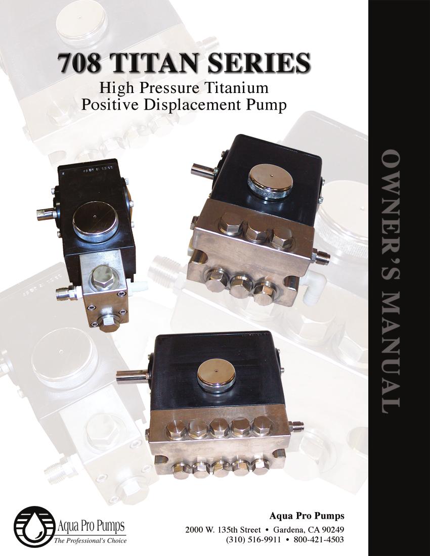
40 INTRODUCTION Aqua Pro Pumps 708 Series High Pressure Pumps are the product of our years of experience in the water treatment industry, and have been specifically designed and engineered for corrosive and high-pressure applications. Your new Aqua Pro Pump is made with dependable and proven technology to meet your highest demands. SPECIFICATIONS Specifications subject to change without notice. Pump type: Reciprocating Plunger (15 GPH) (22 GPH) (29 GPH) (2.3 GPM) (3.5 GPM) (8 GPM) Number of Plungers: Bore: Stroke: Oil Capacity: 6 oz 6 oz 6 oz 19.5 oz 19.5 oz 32 oz Oil Type: Maximum Inlet pressure: Maximum Fluid Temperature: Parker Racor- Village Marine Tec. High Pressure Pump Oil (Part No quart size) Flooded to 60 PSI 120 degrees Fahrenheit (82 degrees Celsius) Model Inlet Port Discharge Port Dimensions Capacity Number Size Size L x W x H Weight Shaft GPH.50 NPT.25 NPT x 5.5 x 4 11 lbs GPH.50 NPT.25 NPT x 5.5 x 4 11 lbs GPH.50 NPT.25 NPT x 5.5 x 4 11 lbs GPM.75 NPT.5 MS x 6 x lbs GPM.75 NPT.5 MS x 6 x lbs GPM.75 NPT.5 MS x 9.5 x lbs
41 708 Series High Pressure Titanium Positive Displacement Pump INITIAL START-UP INFORMATION WARNING This is a positive displacement pump. A properly designed pressure relief safety valve must be installed in the discharge piping. Failure to install such a relief mechanism could result in personal injury or damage to the pump or system. Aqua Pro Pumps does not assume any liability or responsibility for the operation of a customer s high-pressure system. The performance of the pump depends on the entire fluid system and will operate best with the proper installation of plumbing, operation, and maintenance of the pump. LUBRICATION It is recommended that pump be filled with Parker Racor - Village Marine Tec s specially blended high pressure pump oil. To check the oil level, ensure the pump has stopped running. Then look into the sight glass in the side cover. Oil level should be level with the mark on the sight glass (Fig.1). Fig. 1: Oil Level Sight Glass Detail. NOTE Change the original oil that came in the pump after running the pump for 100 hours. After the initial oil change, the oil should be changed at 500-hour service intervals. PUMP FLOW DESIGN To drive the pump to give the desired discharge volume for your specific application equation 2.1 is to be used. Rated GPM Desired Pump RPM : = Rated RPM "Desired" GPM "Desired" RPM (2.1) PULLEY SELECTION It is essential that an appropriate pulley size be selected to meet your application needs. Based on the required pump discharge volume (in GPM), the correct pulley size can be selected using equation
42 CAUTION Pulley should be sized to not exceed the maximum pump RPM rating. Motor Pulley O.D. Pump Pulley O.D. Pulley Size : = Pump RPM Motor RPM (2.2) MOTOR SELECTION To ensure desired pump output, the motor or engine driving the pump must possess sufficient horsepower to maintain full RPM when the pump is under load. Using equation 2.3 an appropriate electric motor can be sized for the application. This motor sizing approach is based on pump discharge volume and maximum pump discharge pressure. The constant in the equation accounts for drive and system losses, which implies a mechanical efficiency of 85%. Consult the manufacturer of a gas or diesel engine for selection of the proper engine size. Refer to Table 1 for sample horsepower applications. GPM PSI HP Required : = Electric Brake HP 1460 (2.3) Table 1: Approximate Horsepower Required HP Required ( GPH) Working Pressure [PSI] Flow [GPH] Speed [RPM] HP Required ( GPH) Working Pressure [PSI] Flow [GPH] Speed [RPM] HP Required ( GPM) Working Pressure [PSI] Flow [GPM] Speed [RPM] HP Required ( GPH) Working Pressure [PSI] Flow [GPH] Speed [RPM] HP Required ( GPM) Working Pressure [PSI] Flow [GPM] Speed [RPM] HP Required ( GPH) Working Pressure [PSI] Flow [GPM] Speed [RPM] MOUNTING THE PUMP The pump should be located as close to the source of supply as possible. Mount the pump on a rigid, horizontal surface allowing easy access for crankcase oil draining. The pump should also be mounted in such a way that inspection can be done with ease. Ensure drive belt is adequately sized for system and shaft bearings. Pulley alignment is critical to the proper operation of the system. To check for proper alignment, place a straight-edge, square, or rule against the pulleys to make sure they 3
43 708 Series High Pressure Titanium Positive Displacement Pump are in line. Proper alignment of the drive pulleys will minimize crankshaft bearing and belt wear. Over tensioning of the drive belt may cause pump crankshaft bearing damage. If the pump will be in service in an environment with a high debris presence or in a humid environment, it is recommended that the pump be enclosed. Do not store or operate in excessively high temperature areas without proper ventilation. DISCHARGE PLUMBING CAUTION Start system with all valves open or with minimal flow restriction to avoid deadhead overpressure conditions and severe damage to the pump or system. Discharge regulating devices should be at minimum pressure setting at start-up. In installations utilizing a Pulsation Dampening device, the device should be mounted directly to the discharge line. Consult dampening device manufacture for optimum pre-charge. A reliable pressure gauge should be installed near the discharge outlet of the manifold. This is extremely important for adjusting pressure-regulating devices; and when appropriate, for sizing of the nozzle or restricting orifice. The pump is rated for a maximum pressure; this is the pressure measured at the discharge manifold of the pump. A pressure relief or unloader valve must be installed to prevent over-pressure in the event that the discharge or downstream plumbing becomes restricted or is turned off. Severe damage to the pump will result if this condition occurs without a relief valve in the line. CAUTION FAILURE TO INSTALL A SAFETY RELIEF VALVE WILL VOID THE WARRANTY ON THE PUMP. On fittings not using o-ring seals, use PTFE liquid sparingly, or tape to connect accessories or plumbing. Do not wrap tape beyond the last thread to prevent tape from becoming lodged in the pump or accessories. This condition will cause a malfunction of the pump or system. PUMPED FLUIDS Some fluids may require a flush between operations or before storing. For pumping fluids other than water, contact your supplier or Parker Racor - Village Marine Tec. CAUTION STORAGE DO NOT RUN PUMP WITH FROZEN FLUID. DO NOT RUN PUMP DRY. For extended storage or between uses in cold climates, drain all pumped fluids from pump and flush with antifreeze solution to prevent freezing and damage to the pump. 4
44 INLET CONDITION CHECKLIST Review this checklist before operation of system. It is critical that all factors are carefully considered and met. INLET SUPPLY Inlet supply should be adequate to accommodate the maximum flow being delivered by the pump. 1. Open inlet valve and turn on supply to avoid starving the pump. CAUTION DO NOT RUN PUMP DRY. 2. Avoid closed loop systems, especially with high temperature, ultra-high pressure or large volumes. Conditions vary with regulating/unloader valve. 3. Low vapor pressure fluids, such as solvents, require positive heads to assure adequate inlet supply. 4. Higher viscosity fluids require that the pump be flooded to 60 PSI to assure adequate inlet supply. 5. Higher temperature fluids tend to vaporize and require positive heads to assure adequate inlet supply. 6. When using an inlet supply reservoir, size it to provide adequate supply of fluid to accommodate 6-10 minutes retention time at the rated GPM (however, a combination of system factors can change this requirement). Provide adequate baffling in the tank to eliminate air bubbles and turbulence. Install diffusers on all return lines to the tank. INLET LINE SIZE Inlet line size should be adequate to avoid starving the pump. Pump suction should never operate in a vacuum. 1. Line size must be sufficient to allow free flow of influent fluid at the pumping flow rate. Minimize the use of thickwalled fittings, tees, 90-degree elbows, or valves in the inlet line of the pump to reduce the risk of flow restriction, vacuum, and cavitation. 2. The inlet line MUST be a FLEXIBLE hose, NOT a rigid pipe, and REINFORCED ON SUCTION SYSTEMS to avoid collapsing. 3. The simpler the inlet plumbing, the less the potential for problems. It is recommended to keep the length, number of joints, and the number of inlet accessories to a minimum. 4. Use pipe sealant as appropriate to ensure airtight positive sealing pipe joints. INLET PRESSURE Inlet pressure should be between flooded (zero) to 60 PSI. 1. High RPM, high temperatures, low vapor pressures, or high viscosity reduces inlet pressure. The pump may require a pressurized inlet to maintain adequate inlet supply. 5
45 708 Series High Pressure Titanium Positive Displacement Pump 2. Optimum pump performance and service life is obtained with 20 PSI (1.4 BAR) inlet pressure. With adequate inlet plumbing, most pumps will perform with flooded suction. Maximum inlet pressure is 60 PSI (5 BAR). 3. After prolonged storage, the pump should be purged of air to facilitate priming. With the pump not running, disconnect the discharge port and allow fluid to pass through pump, then reconnect the discharge port. INLET ACCESSORIES Inlet accessories are designed to protect against over pressurization, control inlet flow, contamination or temperature and provide ease of servicing. 1. An inlet/supply shut-off valve is recommended to facilitate maintenance. 2. A standpipe can be used in some applications to help maintain a positive head in the inlet line. 3. Inspect and clean the inlet filters on a regular schedule, if applicable. 4. A vacuum/pressure gauge should be installed to monitor the inlet pressure. A gauge should be mounted as close to the pump inlet as possible. Short term, intermittent cavitation will not register on a standard gauge. 5. All accessories should be sized to avoid restricting the inlet flow. 6. All accessories should be compatible with the solution being pumped to prevent premature failure or malfunction. 6
46 PREVENTIVE MAINTENANCE SCHEDULE The Required Maintenance Schedule specifies how often you should have your pump inspected and serviced. It is essential that your pump be serviced as scheduled to retain its high level of safety, dependability, and performance. Not performing these tasks could result in catastrophic failure. TASKS DAILY WEEKLY FIRST 100 HRS. EVERY 500 HRS. EVERY 1500 HRS. PLAN FOR EVERY 3000 HRS. EVERY HRS. INSPECTION TASKS Clean Filters* Water Leaks Oil Level X X X Pulley Belts Inspect Plumbing X X X SERVICE TASKS Pump Oil X X Routine Service Kit X Crankcase Rebuild Kit Manifold Rebuild Kit X X Crankshaft Bearings X * If applicable for system 7
47 708 Series High Pressure Titanium Positive Displacement Pump MAINTENANCE RECORD Keep record of all maintenance below to ensure maintenance is performed. Note trends and increase maintenance as necessary. HOURS** RECOMMEND SERVICE ACTIONS / NOTES ACTUAL HOURS SIGNATURE DATE 100 Oil 500 Oil 1000 Oil 1500 Service Kit, Oil 2000 Oil 2500 Oil 3000 Service Kit/Full Kit*, Oil 3500 Oil 4000 Oil 4500 Service Kit, Oil 5000 Oil 5500 Oil 6000 Service Kit/Full Kit*, Oil 6500 Oil 7000 Oil 7500 Service Kit, Oil Crankshaft Bearing, Oil *Replace HP seal only in case of failure (see low-pressure troubleshooting, pg.9). Hours are for reference only (for maintenance planning purposes). ** Oil changes are mandatory at the specified hour intervals. 8
48 TROUBLESHOOTING Use the troubleshooting table below. If problem persists, contact your dealer. PROBLEM PROBABLE CAUSE SOLUTION Low Pressure Belt slippage Make sure the correct belt is used. If the correct belt is used and the belt is slipping, then tighten. Replace belt if worn. Leaky discharge hose Pressure gauge inoperative or not registering correctly. Air leak in inlet plumbing Inlet suction strainer clogged or improperly sized Check connections. Replace hose if worn or cracking. Check pressure with new gauge and replace as needed. Use PTFE liquid or tape to seal the threads. Make certain that the PTFE does not go beyond the last thread. Doing so may damage the pump. Clear the obstruction, or use adequate size for inlet pump connection and fluid being pumped. Relief valve stuck, partially plugged or improperly sized Worn or dirty valves Worn high-pressure seals; abrasives in pump fluid, severe cavitation; inadequate water supply; stressful inlet conditions. Clean and reset relief valve to system pressure and correct bypass. Check supply tank for contamination. Clean valve or replace with a rebuild kit. Replace seals with manifold rebuild kit(not service kit). Install and maintain proper filter, check line size and flow available to pump Pulsation pump runs Faulty pulsation dampener (if a extremely rough, pressure low pulsation dampener has been installed.) Restricted inlet, or air entering inlet plumbing Valve or spring damage Seal damage Check pre-charge. Check manufacturer s literature on recommended pressure. Be sure that inlet hose is the proper size. Check filters and clean as needed. Check fittings and use PTFE liquid or tape for airtight connection. Clean or replace valve and spring, check inlet supply tank for contamination Replace seals with manifold rebuild kit(not service kit). Slight water leakage from under the manifold Possible condensation Worn low pressure seals No fix needed. Replace seals with Manifold Service Kit (not Rebuild Kit), check inlet pressure and inspect ceramic plunger for damage. Excessive oil leak between crankcase and pumping section Worn crankcase oil seals Replace crankcase oil seals. 9
49 708 Series High Pressure Titanium Positive Displacement Pump PROBLEM PROBABLE CAUSE SOLUTION Oil leaking in the area of the crankshaft Worn crankshaft oil seal Bad bearing Cut or worn o-ring on bearing case Replace damaged oil seals. (Purchase crankcase rebuild kit, not service kit) Replace bearing. Replace o-ring on bearing case. Water in crankcase Humid air condensing into water inside the crankcase Worn or improperly installed crankcase oil seals Change oil every three months or 300 hours Replace seals; follow proper installation procedure. Excessive water leaking through low pressure seals Replace seals with manifold rebuild kit(not service kit). Excessive play in the end of the crankshaft Worn bearing Replace bearing. Oil leaking in the rear portion of the crankcase Damaged or improperly installed Replace crankcase cover o-ring or drain-plug o-ring. crankcase cover, crankcase cover o-ring, drain-plug, or drainplug o-ring. Loud knocking noise in pump Pulley loose on crankshaft Restricted Inlet Worn bearing, connecting rod or crankshaft. Worn belts Check key and tighten setscrew. Clear obstruction or replace valve. Consult supplier for crankcase servicing. Replace belts. Frequent or premature failure of the seals Running pump dry Abrasive material in the fluid being pumped Excessive temperature of pumped fluid (120 degrees F max.) NEVER RUN THE PUMP WITHOUT WATER. Install proper filtration on pump inlet plumbing. Reduce fluid inlet temperature to specifications. 10
50 PROBLEM PROBABLE CAUSE SOLUTION Strong surging at the inlet and low pressure Foreign particles in the inlet or discharge valve or worn inlet or discharge valves Restricted fluid flow Check for smooth surfaces on inlet and discharge valve seats. If signs of wear or damage are present return to factory for service. Check supply tank for contamination, regularly clean filter. Do not pump abrasive fluid. Check the Inlet Conditions Checklist. 11
51 708 Series High Pressure Titanium Positive Displacement Pump SERVICE An authorized technician should perform all service. CAUTION Ensure pump is disconnected from the motor or any driving devices. Service the pump in a clean, dirt-free environment. Pump rebuild kits are available for seal overhauls. Contact your dealer for ordering information. INTRODUCTION All tasks should be performed in a clean environment, free from dust and debris. It is imperative that utmost cleanliness be maintained during the rebuild of your Aqua Pro Pump. The numbers following the parts are call out numbers. They correspond to the parts on the drawings. READ THE INSTRUCTIONS COMPLETELY BEFORE ATTEMPTING TO PERFORM ANY SERVICE. Before assembling any parts, clean all parts to make free of oil, grease, dirt, and lint. Use a lint free cloth to wipe any part of the pump. NOTE A light coating of Anti-Seize Lubricant (PN ) should be applied on all threaded parts, unless otherwise stated. Only silicon grease (PN ) should be used on all o-rings and seals. Use of any other type of grease may result in o-ring or seal failure. TOOLS NEEDED Table 2: Tool List for Pump Service 3/16 Allen Wrench Phillips Head Screwdriver 1/4 Allen Wrench Pick 7/16" Socket/ Socket Wrench or Combination Wrench Snap Ring Pliers 9/16" Socket/ Socket Wrench or Combination Wrench Torque Wrench (220 in.-lb.) 1/2 Socket/ Socket Wrench or Combination Wrench Weep Ring Removal Tool (PN ) 3/4" Socket/ Socket Wrench or Combination Wrench Dead Blow Hammer 7/8" Socket/ Socket Wrench or Combination Wrench Flat Head Screwdriver 7/8" Combination Wrench 12
52 DETACHING THE MANIFOLD FROM THE CRANKCASE You will need these tools and parts to do the following: 9/16 Socket/ Socket Wrench (for 708-5) 1/2 Socket/ Socket Wrench (for 708-3) 3/16 Allen Wrench (for 708-1) Dead Blow Hammer Remove the two manifold bolts (58) with a 9/16 socket wrench for the 708-5, with a 1/2 socket wrench for the 708-3, or the 4 socket head bolts with the 3/16 Allen wrench for the Loosen the manifold assembly by lightly tapping off the manifold using the dead blow hammer, as seen in Fig. 2. Tap the manifold from both sides to apply even force to the manifold. Failing to do so can result in damage to the Ceramic Plungers. Set the manifold assembly aside in a clean work area. If the manifold assembly locating dowel pins (53) fall out, reinsert them into the manifold alignment pin holes. Fig. 2: Manifold Assembly Removal ROUTINE SERVICE KIT The following are the part numbers for the 708 Series Routine Service Kits Routine Service Kit (PN ) , 2.3 Routine Service Kit (PN ) , 3.5 Routine Service Kit (PN ) Routine Service Kit (PN ). The Manifold Assembly must be detached from the crankcase to do the following service. VALVE ASSEMBLY ROUTINE SERVICE You will need these tools and parts to do the following: 7/8" Socket Wrench or Combination Wrench P ick Spring, Valve (45): PN Valve, Standard, 708 Series (44): PN (For & ) Assembly, Valve, Heavy Duty, 708 Series (44): PN (For & 708-5) O-Ring, Valve Plug (46): PN Silicone Grease Lubricant: PN Anti-Seize Lubricant: PN Lint-Free Cloths 13
53 708 Series High Pressure Titanium Positive Displacement Pump When the manifold assembly has been removed from the crankcase assembly, place the assembly on a clean work surface. Remove all of the valve plug assemblies from the manifold assembly using a 7/8 socket wrench or combination wrench. Remove the valve (44) from the assembly, followed by the valve spring (45). With the aide of a pick remove the o-ring (46) from the valve plug. NOTE Valve plugs (47) will be reused. A light coating of silicon grease (PN ) should be used on all new o-rings and seals. Use of any other type of grease may result in o-ring or seal failure. Clean and inspect all valve plugs (47) prior to reassembling. If there is a problem, contact your dealer. Once all valve plugs (47) are clean and dry, install new valve plug o-ring (46) onto valve plug (47). Install the valve spring (45) onto the valve plug (47), it should now be attached to the plug. Press the valve (44) onto the valve spring (45). Complete valve assembly shown in Fig. 3. Fig. 3: Valve Assembly (NOTE: There are two different valve plug designs) NOTE A light coating of Anti-Seize Lubricant (PN ) should be applied on all threaded parts, unless otherwise stated. Inspect the manifold (38) for debris or other fouling and clean if necessary. Inspect the valve seat surface in the manifold. If there is a problem contact your dealer. Reinstall all the valve plug assemblies with a 7/8" socket wrench or combination wrench and tighten. MANIFOLD SEAL ROUTINE SERVICE NOTE You will need these tools and parts to do the following: Flat screw driver Seal, LP (45): PN Silicone Grease Lubricant: PN Lint-Free Cloths 14 Pump manifold assembly must be detached from the crankcase assembly to service the seals.
54 For manifold seal servicing purposes the manifold must be placed with the valve plugs sitting on a flat surface and the plunger bores facing upward. This will facilitate service technician access to the seals for removal and installation, as shown in Fig. 4. Fig. 4: Orientation for Manifold Seal Servicing A light coating of silicon grease (PN ) should be used on all new o-rings and seals. Use of any other type of grease may result in o-ring or seal failure. With a flat screw driver remove the low-pressure seal (43). Ensure that the low-pressure seal spacer (39) was not accidentally removed when the low-pressure seal was removed and press in the new low-pressure seal (43). CRANKCASE SEAL ROUTINE SERVICE Remove the seal retainer (29) and set aside. Remove the plunger retainer bolt (28) with a 7/16 wrench, set aside. There is no need to remove the plunger retainer washer (28) or plunger retainer o-rings (27) from the plunger retainer bolt (28). Remove the ceramic plunger (26). Remove the slinger (25) and the outer washer (6). With the aid of the pick remove the plunger rod oil seal (7) from the crankcase. Inspect the seal retainer washers (8) for damage, if none evident then reuse, if damage is evident consult the factory. A light coating of silicon grease (PN ) should be used on all new o-rings and seals. Use of any other type of grease may result in o-ring or seal failure. Insert new plunger rod oil seal (7) into crankcase making sure that the seal is fully seated, place outer washer (6) on seal. Place slinger (25) onto the plunger rod (9). NOTE Examine the ceramic plungers (26) for cracks, heavy scoring, or unusual wear. If there is a problem, contact your dealer. Slide ceramic plungers (26) onto plunger rod and insert the plunger retainer washer (28) into the plunger. Clean the plunger retaining bolt s (29) threaded area. If they were removed replace the o-rings (27) onto the plunger retainer (29). Slide the plunger retaining washer (28) onto the plunger retainer (29). 15
55 708 Series High Pressure Titanium Positive Displacement Pump Fig. 5: Plunger Retaining Bolt Assembly Apply Red Loctite # 262 to retainer bolt (29) threads. Reinstall the plunger retainer bolt (29) and torque to 100 in. lb. using a 7/16 socket. NOTE Be CAREFUL not to get the red loctite on any other components. Apply Aqua Pro s special Ceramic Lubricant (PN ) to the ceramic plungers (26). Slide the seal retainer over the ceramic plungers (26). Make sure that the flanged side is close proximity to the manifold assembly, and that hole is oriented downward ensuring that the seal retainer has adequate water drainage. Routine service is now complete. Fig. 6: Seal Retainer 16
56 SERVICING THE CRANKCASE The following are the procedures for servicing the crankcase assembly using the Crankcase Rebuild Kit (PN ) Crankcase Rebuild Kit (PN ) Crankcase Rebuild Kit (PN ). The manifold assembly must be detached from the crankcase to do the following service. OIL DRAIN PLUG O-RING REPLACEMENT You will need these tools and parts to do the following: 7/8 Socket/ Socket Wrench P ick O-Ring, Drain Plug (4): PN Anti-Seize Lubricant: PN Silicon Grease Lubricant: PN Remove the oil drain plug with a 7/8 wrench and drain the crankcase oil. Clean the drain plug (5), remove the o-ring (4) with the aide of the pick if necessary. Replace with the new one supplied in the kit. Apply anti-seize lube to the threads of the drain plug (5) and reinstall. PLUNGER ROD SEAL REPLACEMENT You will need these tools and parts to do the following: 7/16 Socket/ Socket Wrench Torque Wrench Seal, Oil, Plunger Rod (7): PN Washer, Plunger Retainer (27): PN O-Ring, Plunger Retainer (26): PN Slinger Barrier (24): PN Ceramic Lubricant: PN Silicone Grease Lubricant: PN Red Loctite # 262 Lint-fre e Cloths Remove the seal retainer (29) and set aside. Remove the plunger retainer bolt (28) with a 7/16 wrench, set aside. Remove the plunger retainer washer (28) and remove the ceramic plunger (26). Remove the slinger (25) and the outer washer (6). With the aide of the pick remove the plunger rod oil seal (7) from the crankcase. Inspect the seal retainer washers (8) for damage, if none evident then reuse, if damage is evident consult the factory. NOTE A light coating of silicon grease (PN ) should be used on all new o-rings and seals. Use of any other type of grease may result in o-ring or seal failure. Insert new plunger rod oil seal (7) into crankcase making sure that the seal is fully seated, place outer washer (6) on seal. Place slinger (25) onto the plunger rod (9). 17
57 708 Series High Pressure Titanium Positive Displacement Pump NOTE Examine the ceramic plungers (26) for cracks, heavy scoring, or unusual wear. If there is a problem, contact your dealer. Slide ceramic plungers (26) onto plunger rod and insert the plunger retainer washer (28) into the plunger. Clean the plunger retaining bolts (29). With the aide of a pick, remove the plunger retainer o-ring (27). Replace the o-ring (27) with the new one supplied in the kit as shown in Fig. 6. Slide the plunger retaining washer (28) onto the plunger retainer (29). Fig. 5: Plunger Retaining Bolt Assembly Apply Red Loctite # 262 to retainer bolt (29) threads. Reinstall the plunger retainer bolt (29) and torque to 100 in. lb. using a 7/16 socket. NOTE Be CAREFUL not to get the red loctite on any other components. Apply Aqua Pro s special Ceramic Lubricant (PN ) to the ceramic plungers (26). Slide the seal retainer over the ceramic plungers (26). Make sure that the flanged side is close proximity to the manifold assembly, and that hole is oriented downward ensuring that the seal retainer has adequate water drainage. Fig. 6: Seal Retainer BEARING SIDE PLATE O-RING/SEAL REPLACEMENT You will need these tools and parts to do the following: 3/16" Allen Wrench Philips Head Screw Driver 18
58 P ick Seal, Oil, Crankshaft (18): PN (708-1, 708-3) (708-5) O-Ring, Bearing Side Plate (15): PN O-Ring, Sight Glass (22): Silicon Grease Lubricant: PN Anti-Seize Lubricant: PN Remove the 4 socket head cap screws (19) with a 3/16 Allen Wrench from each of bearing side plate (16), (17), this applies to the 708-1, GPM, and the pumps. With the aide of a pick remove the o-rings from the grooves, remove the crankshaft oil seal (18) from the pulley side bearing cap (17). For GPM pumps with direct drive, uncouple the pump from the motor. Remove the 4 Philips head screws (36) holding the bell housing (34) to the pump. Now remove the bearing side plate (17), o-rings and seal can now be replaced. Remove the sight glass retainer (24) from the bearing side plate (16). With the aide of a pick remove the sight glass o-ring (22). Replace o-ring with the one provided in the kit. CAUTION Crankshaft oil seal is press fit at the factory, care is to be exercised during removal so damage does not occur to sealing surface. NOTE A light coating of silicon grease (PN ) should be used on all new o-rings and seals. Use of any other type of grease may result in o-ring or seal failure. Press new crankshaft oil seal (18) into pulley side bearing cap (17), Install o-ring (15) in o-ring groove on the crankshaft bearing caps (16), (17) and reinstall caps on pump. NOTE A light coating of Anti-Seize Lubricant (PN ) should be applied on all threaded parts, unless otherwise stated. Install the 4 socket head cap screws (19) onto each of the bearing side plates and tighten with a 1/4 Allen Wrench. This applies to the 708-1, GPM, and the pumps. For the GPM pump, reinstall the bell housing (34) by installing the 4 Philips head screws (36). CRANKCASE COVER O-RING REPLACEMENT In this procedure you will replace the o-rings on the crankcase cover as provided in the rebuild kit. You will need these tools and parts to do the following: 3/16 Allen Wrench Phillips Head Screwdriver P ick Silicone Grease Lubricant: PN Red Loctite # 262 Anti-Seize Lubricant: PN
59 708 Series High Pressure Titanium Positive Displacement Pump Unscrew the crankcase cover screws (19) with the 3/16 Allen wrench. With the aide of the pick remove the crankcase cover o-ring (20). NOTE A light coating of silicon grease (PN ) should be used on all new o-rings and seals. Use of any other type of grease may result in o-ring or seal failure. Install the new crankcase cover o-ring (20) provided with the rebuild kit. NOTE A light coating of Anti-Seize Lubricant (PN ) should be applied on all threaded parts, unless otherwise stated. Reinstall the crankcase cover and tighten the crankcase cover screws (19) with the 3/16 Allen wrench. CRANKSHAFT BEARING, CONNECTING ROD-PISTON ASSEMBLY SERVICE It is recommended that any service to the crankshaft bearings (16) or to the connecting rod-piston assembly be done by the factory. Due to the high precision required only factory trained personnel are recommended for this service. Performing any maintenance other than rebuild and service kits voids the warranty if not performed by factory trained personnel. SERVICING THE MANIFOLD The following are the procedures for servicing the crankcase assembly using the Manifold Rebuild Kit (PN ) GPM Manifold Rebuild Kit (PN ) GPM Manifold Rebuild Kit (PN ) Manifold Rebuild Kit (PN ). 8 GPM Pump Manufactured After Feb Manifold Rebuild Kit (PN ). 7 GPM Pump Manufactured Before Aug 2002 The manifold assembly must be detached from the crankcase to do the following service. 20
60 Fig. 7: Manifold Assembly INLET/DISCHARGE ADAPTER O-RING REPLACEMENT & You will need these tools and parts to do the following: 3/4 Socket/ Socket Wrench P ick O-Ring, Discharge Plug Adapter (48): PN Silicone Grease Lubricant: PN Anti-Seize Lubricant: PN Remove the Discharge/Plug (50) and (49) adapters from the manifold assembly with the 3/4 Socket/ Socket Wrench. With the aide of a pick remove the o-rings (48) from each of the adapters. NOTE A light coating of silicon grease (PN ) should be used on all new o-rings and seals. Use of any other type of grease may result in o-ring or seal failure. Install the new o-rings (48) provided with the kit onto each of the adapters. NOTE A light coating of Anti-Seize Lubricant (PN ) should be applied on all threaded parts, unless otherwise stated. Reinstall each of the adapters onto the manifold assembly, tighten adapter with 3/4 Socket/ Socket Wrench. VALVE ASSEMBLY SERVICING You will need these tools and parts to do the following: 7/8" Socket Wrench or Combination Wrench P ick 21
61 708 Series High Pressure Titanium Positive Displacement Pump Spring, Valve (45): PN Valve (44): PN O-Ring, Valve Plug (46): PN Silicone Grease Lubricant: PN Anti-Seize Lubricant: PN Lint-Free Cloths NOTE Valves may be serviced while the manifold assembly is attached to the crankcase assembly. If manifold assembly has been removed from the crankcase assembly, place the assembly on a clean work surface. Remove all of the valve plug assemblies from the manifold assembly using a 7/8 socket wrench or combination wrench. Remove the valve (44) from the assembly, followed by the valve spring (45). With the aide of a pick remove the o-ring (46) from the valve plug. NOTE Valve plugs (47) will be reused. A light coating of silicon grease (PN ) should be used on all new o-rings and seals. Use of any other type of grease may result in o-ring or seal failure. Clean and inspect all valve plugs (47) prior to reassembly. If there is a problem, contact your dealer. Once all valve plugs (47) are clean and dry, install new valve plug o-ring (46) onto valve plug (47). Install the valve spring (45) onto the valve plug (47), it should now be attached to the plug. Press the valve (44) onto the valve spring (45). Complete valve assembly shown in Fig. 9. Fig. 8: Valve Assembly (NOTE: There are two different valve plug designs) NOTE A light coating of Anti-Seize Lubricant (PN ) should be applied on all threaded parts, unless otherwise stated. Inspect the manifold (38) for debris or other fouling and clean if necessary. Inspect the valve seat surface in the manifold. If there is a problem contact your dealer. Reinstall all the valve plug assemblies with a 7/8" socket wrench or combination wrench and tighten. 22
62 MANIFOLD SEAL SERVICING NOTE Pump manifold assembly must be detached from the crankcase assembly to service the seals. You will need these tools and parts to do the following: Snap Ring Pliers Tool, Weep Ring Puller, 708 Series: PN Flat screw driver Seal, HP (40): PN Ring, Snap (42): PN Assembly, Weep Ring (41): PN Seal, LP (43): PN Silicone Grease Lubricant: PN Lint-Free Cloths For manifold seal servicing purposes the manifold must be placed with the valve plugs sitting on a flat surface and the plunger bores facing upward. This will facilitate service technician access to the seals for removal and installation, as shown in Fig. 10. Fig. 9: Orientation for Manifold Seal Servicing With a flat screw driver remove the low-pressure seal (43). Manually remove the low-pressure seal spacer (39). With the snap ring pliers remove the snap ring (42). Using the weep ring extracting tool remove the weep ring assembly (41) as shown in Fig. 11. NOTE Extraction of the rings is accomplished by inserting tool in relaxed state into the inner diameter of the rings, then tighten the expansion bolt to grip the ring. Install the extraction stand and nut, tightening nut will extract to weep ring and isolating ring from manifold. 23
63 708 Series High Pressure Titanium Positive Displacement Pump Fig. 10: Weep Ring Extraction With a flat screwdriver remove the high-pressure seals (40). Manually remove the high-pressure seal spacer (40). You must clean and inspect the following parts for re-use: Spacer, High-Pressure Seal (39): PN Spacer, Low-Pressure Seal (39): PN Insert the high-pressure seal spacer (39) into the bore. NOTE A light coating of silicon grease (PN ) should be used on all new o-rings and seals. Use of any other type of grease may result in o-ring or seal failure. Insert the high-pressure seal (40) into the bore until the seal is fully seated on the high-pressure seal spacer (39). Insert the weep ring (41) into the bore after the installation of the high-pressure seals (39). Install the snap ring (42) using the snap ring pliers. NOTE Insert the low-pressure seal spacer (39) and press in the new low-pressure seal (43). The manifold seal servicing is complete. ATTACHING THE MANIFOLD TO THE CRANKCASE You will need these tools and parts to do the following: 9/16 Socket/ Socket Wrench (for 708-5) 1/2 Socket/ Socket Wrench (for 708-3) 3/16 Allen Wrench (for 708-1) Dead Blow Hammer Dead Blow Hammer Manifold Bolt (58): PN (for 708-5) Manifold Bolt (58): PN (for 708-3) Manifold Screw (58): PN (for 708-1) Ceramic Lubricant: PN Anti-Seize Lubricant: PN Ensure that the snap ring (42) is fully seated in the snap ring groove before continuing.
64 If a crankcase seal rebuild was not performed at this time then ensure that the dowel locating pins (53) are pressed into their corresponding hole. Ensure that ceramic lubricant is applied to the ceramic plunger assemblies and that the seal retainers are installed with the flange located away from the crankcase assembly. NOTE A light coating of Anti-Seize Lubricant (PN ) should be applied on all threaded parts, unless otherwise stated. Align manifold assembly to crankcase assembly and tighten the two manifold bolts (58) with a 9/16 socket wrench for the 708-5, with a 1/2 socket wrench for the 708-3, or the 4 socket head bolts with the 3/16 Allen wrench for the
65 708 Series High Pressure Titanium Positive Displacement Pump 26
66 708-1 DRAWINGS
67 D C B A NOTES: 1) ASSEMBLY PART NUMBERS ARE AS FOLLOWS: ASSY, CRANKCASE, 708-1,.200 CRANKSHAFT ASSY, CRANKCASE, 708-1,.300 CRANKSHAFT ASSY, CRANKCASE, 708-1,.400 CRANKSHAFT KIT, REBUILD, CRANKCASE, KIT, ROUTINE SERVICE, ) ITEMS 9,10 AND 11 MAY BE PURCHASE UNDER THE FOLLOWING PART NUMBER: ASSY, DRIVE, 708 SERIES PUMPS 3) PUMP CRANKSHAFTS ARE STAMPED WITH A NUMBER 2, 3, OR 4 ON THE END THIS DENOTES THE OFFSET OF THE CRANKSHAFT STROKE. SEE DESCRIPTION FOR ITEM (12) NOT USED NOT USED NOT USED NOT USED NOT USED NOT USED PLUG, CRANKCASE RETAINER, SEAL, 708 SERIES WASHER, PLUNGER RETAINER, 708 SERIES BOLT, PLUNGER RETAINER, 708 SERIES O-RING, PLUNGER RETAINER PLUNGER, 708 SERIES SLINGER, PLUNGER, 708 SERIES RETAINER, SIGHTGLASS SIGHTGLASS, OIL O-RING, OIL SIGHTGLASS COVER, CRANKCASE, O-RING, REAR COVER, SCREW, COVER SEAL, OIL, CRANKSHAFT, 708-1/ CAP, PULLEY BEARING, 708 SERIES CAP, GUIDE BEARING, 708 SERIES O-RING, BEARING CAP BEARING, CRANKSHAFT, 708-1/ RING, SNAP, BEARING, 708 SERIES CRANKSHAFT, 708-1, 29 GPH (.4" STROKE) CRANKSHAFT, 708-1, 22 GPH (.3" STROKE) CRANKSHAFT, 708-1,15 GPH (.2" STROKE) ASSY, CONNECTING ROD, 708 SERIES PIN, DOWEL, M9, 22, STL PLUNGER, 708 SERIES WASHER, OIL SEAL, INNER, 708 SERIES SEAL, OIL, 708 SERIES WASHER, OIL SEAL, OUTER, 708 SERIES PLUG, MS O-RING, PLUG, OIL DRAIN/HP DISCHARGE CAP, OIL FILLER, PUMP, 708 SERIES O-RING, OIL FILLER CAP CRANKCASE,708-1,AL ITEM PART NUMBER DESCRIPTION QTY.200 STROKE QTY.300 STROKE QTY.400 STROKE QTY REBUILD KIT QTY SERVICE KIT SIZE B TITLE 23 ASSEMBLY, CRANKCASE DATE: REV - B CHAIDEZ SHEET 1 OF D C B A
68 D C B A NOTES: 1) ASSEMBLY PART NUMBERS ARE AS FOLLOWS: ASSY, MANIFOLD, KIT, REBUILD, MANIFOLD, KIT, SERVICE KIT, ADAPTER, LP INLET, ADAPTER, HP DISCHARGE, PIN, MANIFOLD, 708 SERIES NOT USED NOT USED NOT USED NOT USED NOT USED PLUG,VALVE,STANDARD,708 SERIES O-RING, OIL DRAIN/VALVE PLUG SPRING, VALVE, 708 SERIES VALVE, 708 SERIES SEAL, LP, 708 SERIES RING, SNAP, 708 SERIES ASSY, WEEP RING, 708 SERIES SEAL, HP, 708 SERIES RING, SPACER, SEAL, 708 SERIES MANIFOLD, ITEM PART NUMBER DESCRIPTION QTY QTY REBUILD KIT QTY SERVICE KIT SIZE B TITLE REV ASSEMBLY, MANIFOLD DATE: B CHAIDEZ SHEET 1 OF D C B A
69 D C B A NOTES: 1: ASSEMBLY PART NUMBERS ARE AS FOLLOWS: PUMP, 708-1,.200 CRANKSHAFT PUMP, 708-1,.300 CRANKSHAFT PUMP, 708-1,.400 CRANKSHAFT SCREW, MANIFOLD ASSEMBLY, MANIFOLD ASSEMBLY, CRANKCASE ASSEMBLY, CRANKCASE ASSEMBLY, CRANKCASE ITEM PART NUMBER 8 DESCRIPTION 7 QTY GPD QTY GPD 6 QTY GPD SIZE B TITLE REV ASSEMBLY, MAIN DATE: B CHAIDEZ SHEET 1 OF 1 1 D C B A
70 MANUFACTURER S LITERATURE JAN 2010, REV.- 29


71 Aqua Pro Sea Water RO Membranes Contact Information: Parker Hannifin Corporation Racor Division/Village Marine Tec W. 135th St. Gardena, CA phone fax Aqua Pro thin film composite reverse osmosis membranes deliver high salt rejection while maintaining high production rates to obtain the energy efficiency demanded by plant operators. By selecting the highest grade of materials and thoroughly testing performance, Racor Village Marine Tec. is able to offer the highest quality products. Aqua Pro membranes are designed for use in Parker Village Marine Tec. pressure vessel housings as well as other brand housings.
72 Aqua Pro Sea Water RO Membranes Recommended Operating Limits: B TYP Maximum Operating Pressure: 1000 psi Maximum Operating Temperature: 113 F (45 C) Maximum Feed Turbidity: 1 NTU Free Chlorine Tolerance: 0 PPM A Maximum Feed Silt Density Index: SDI 5 ph Range: Continuous Operation: 4-11 Short-term for Cleaning: (30 minute duration) D C 15 VMT Part No ** ** ** Nominal Size Product Flow GPD m 3 /day Typical Salt Rejection % A* 19/48 19/48 19/48 38/ / / /101.6 B 1.1/ / / / / / /3.2 Dimensions inches/cm C 0.75/ / / / / / /3.8 D 2.4/ / / / / / /15.2 * All 19 and 38 elements come with a 2 removable extender so that the stocked size also fits 21 and 40 housings ** Elements are specially designed for low feed flow applications. Use only with certain Sea Quencher and Little Wonder watermakers. Notes: Keep elements moist at all times Permeate obtained from first two hours of operation should be discarded To prevent biological growth during storage, shipping, or system shutdowns it is recommended that elements be immersed in a protective solution. The standard solution for long or short term storage should contain 1.0 percent (by weight) sodium metabisulfite (available as VMT p/n , , or ) Standarized test conditions are 32,000 ppm NaCl at 77 F (25 C), with 800 psi feed. Production rates for individual elements may vary +/- 20% and rejection may vary +/- 0.4% To maintain peak performance always use genuine Parker-Racor/Village Marine Tec. replacement parts. We reserve the right to change our specifications or standards without notice Parker Hannifin Corporation Print Reorder Number 7897 Rev


73 Pressure Vessel Assemblies For Seawater Elements Contact Information: Parker Hannifin Corporation Racor Division/Village Marine Tec W. 135th St. Gardena, CA phone fax Key Features: Racor Village Marine RO membrane pressure vessels feature non-metallic wetted surfaces for excellent corrosion resistance. Simple end plug design allows quick removal for element servicing. If the size you require is not shown please contact us for custom builds. Operating Pressure: 1000 psi/68 bar Shell: Filament Wound fiberglass Collars: 6061 T-6 Powdercoated aluminum End Plugs: Thermoplastic End Ring: 6061 T-6 Anodized aluminum on 2.5 and 4 size SS316 on 6 size Fasteners: SS316
74 Pressure Vessel Assemblies For Seawater Elements Part Numbers: 1 Item Description Quantity per Assembly 2.5 x x 38 4 x 40 6 x 40 1 Vessel Assembly** * Product O-ring End Plug O-ring End Plug * * End Ring Capscrews *** Shell White Gray Please Call Please Call Weight (lbs/kg) 5/2 7/3 22/10 45/20 Notes: *End Plug is also available for 2.5 vessels, which offers straight, coarse thread feed/reject port used on some VMT PW watermakers. Use of coarse thread end plug changes the vessel assembly p/n to **Membrane not included. For applicable membrane elements see bulletin No (Aqua Pro RO Membranes) *** Capscrews: Order 6 per end plug on 2.5 size Order 8 per end plug on 4 size Order 10 per en plug on 6 size To maintain peak performance always use genuine Parker-Racor/Village Marine Tec. replacement parts. We reserve the right to change our specifications or standards without notice Parker Hannifin Corporation Print Reorder Number 7898 Rev-A


75 Pleated Filters and Filter Cartridge Kits Contact Information: Parker Hannifin Corporation Racor Division/Village Marine Tec W. 135th St. Gardena, CA phone fax The Village Marine Tec. line of pleated filters are designed specifically for the RO watermaker industry and are superior to wound or polyspun cartridges to give you a longer filter life as well as increasing flow rates and keeping cartridge size down. Available in a wide arrange of sizes and micron ranges to ensure that every type of watermaker filter need is taken care of. Stock sizes fit most standard filter housings, if the size you need is not shown please contact us with the dimensions required. Single use Cleaning and Preservative Cartridge Kits are designed specifically for small RO Systems. The Cartridges allow for easy and effective membrane maintenance. The Cleaning and Preservative Cartridge Kits eliminate the trouble and mess of measuring powdered chemicals and ensuring correct chemical concentrations. The Chemical cartridges fit directly into 2.5 x 10 housings and contain the correct amount of chemical for a single use.
Village Marine LWM The Little Wonder Modular Installation, Operation & Maintenance
 Village Marine LWM 145-200 The Little Wonder Modular 145-200 Installation, Operation & Maintenance TABLE OF CONTENTS 1.0 INTRODUCTION 1 1.1 UNPACKING AND HANDLING 2 1.2 PERFORMANCE SPECIFICATIONS 2 1.3
The Sea Quencher Installation, Operation & Maintenance. Racor Offshore Marine Sea Quencher
 Racor Offshore Marine Sea Quencher The Sea Quencher 145200 Installation, Operation & Maintenance Contact: Green Marine & Industrial Equipment Co., Inc. www.greenmarine.com TABLE OF CONTENTS 1.0 INTRODUCTION
Village Marine-PW Part Number: Pure Water Series PW 8,000-20,000 GPD. Installation, Operation & Maintenance
 Village Marine-PW 3000 Part Number: 95-0027 Pure Water Series PW 8,000-20,000 GPD Installation, Operation & Maintenance TABLE OF CONTENTS 1.0 SYSTEM DESCRIPTION 1 1.1 SPECIFICATIONS 1 1.1.1 PERFORMANCE
ISLAND EXPLORER SERIES REVERSE OSMOSIS DESALINATOR INSTALLATION & OPERATION MANUAL
 ISLAND EXPLORER SERIES REVERSE OSMOSIS DESALINATOR INSTALLATION & OPERATION MANUAL 3000 E 2 ND STREET THE DALLES, OR 97058 USA PHONE: 800-548-4502 541-296-4562 FAX: 541-296-3954 uswatermaker@gorge.net
VENTURA 150 DELUXE INSTALLATION MANUAL
 VENTURA 150 DELUXE INSTALLATION MANUAL Spectra Watermakers, Inc. 20 Mariposa Road, San Rafael, CA 94901 Phone 415-526-2780 Fax 415-526-2787 E-mail: spectra@spectrawatermakers.com www.spectrawatermakers.com
Flow Max. by Duraself. Flow Max by Duraself. Fluid Pump. Installation and Owner s Manual (For Aftermarket Applications)
") Flow Max Installation and Owner s Manual (For Aftermarket Applications) Table of Contents Introduction... 2 Parts List... 2 Resources Required... 3 Installation... 3 General Installation Instructions...
Flow Max Installation and Owner s Manual (For Aftermarket Applications) Table of Contents Introduction... 2 Parts List... 2 Resources Required... 3 Installation... 3 General Installation Instructions...
Flow Max Fluid Pump. by Duraself OEM INSTALLATION MANUAL
 Flow Max Fluid Pump by Duraself OEM INSTALLATION MANUAL TABLE OF CONTENTS System and Safety Information 2 Resources Required 3 Installation 3 General Installation Instructions 3 Mounting Instructions 3
Rev: Flow Max 115V AC Fluid Pump
 Flow Max 115V AC Fluid Pump by Duraself Installation and Owner s Manual (For Aftermarket Applications) Table of Contents Introduction... 2 Parts List... 2 Resources Required... 3 Installation... 3 General
Series CP200. Triplex Ceramic Plunger Pump Operating Instructions/ Repair and Service Manual. For Models: CP218 CP219 CP220 CP230
 Series CP200 Triplex Ceramic Plunger Pump Operating Instructions/ Repair and Service Manual For Models: CP218 CP219 CP220 CP230 Updated 10/02 Contents: Installation Instructions: page 2 Pump Specifications:
OWNER S MANUAL. Model: UTL-60-12V ( ) (60 Gallon Lawn & Garden Utility Sprayer w/5-nozzle Boom)
 (60 Gallon Lawn & Garden Utility Sprayer w/5-nozzle Boom)") OWNER S MANUAL Model: UTL-60-12V (5301347) (60 Gallon Lawn & Garden Utility Sprayer w/5-nozzle Boom) Technical Specifications 60 Gal. Corrosion-Resistant Polyethylene Tank Deluxe Pistol-Grip Handgun w/25
OWNER S MANUAL Model: UTL-60-12V (5301347) (60 Gallon Lawn & Garden Utility Sprayer w/5-nozzle Boom) Technical Specifications 60 Gal. Corrosion-Resistant Polyethylene Tank Deluxe Pistol-Grip Handgun w/25
OWNER S MANUAL D.E. CARTRIDGE. Installation Operation Parts. Models PCDE-30 PCDE-40
 D.E. CARTRIDGE OWNER S MANUAL Installation Operation Parts Models PCDE-30 PCDE-40 2200 East Sturgis Road, Oxnard, CA 93030 Ph. (805) 981-0262 Fax (805) 981-9403 www.waterwayplastics.com waterway@waterwayplastics.com
Operation and Maintenance. S100 Series Centrifugal Fire Pumps. Table of Contents. Visit us at F /22/02 6/21/18
 S100 Series Centrifugal Fire Pumps Operation and Maintenance Form No. F-1031 Section 2117 Issue Date 02/22/02 Rev. Date 6/21/18 Table of Contents Safety Information-----------------------------------------------
Installation, Operation & Maintenance Manual
 Installation, Operation & Maintenance Manual Picture may differ from your specific application For Pro-Fill kits with part numbers beginning in BG BL-175 9-20-13 General Information & Precautions This
Model AM2 M40 Panel Installation, Operation, and Maintenance Manual
 Model AM2 M40 Panel Installation, Operation, and Maintenance Manual RECEIVING AND INSPECTION Upon receiving unit, check for any interior and exterior damage, and if found, report it immediately to the
P SERIES PUMPS. 18mm Versions Nickle-Aluminum Bronze Models: P , P , P , P , P , P , P
 P200-3100 SERIES PUMPS 18mm Versions Nickle-Aluminum Bronze Models: P217-3100, P218-3100, P219-3100, P220-3100, P221-3100, P227-3100, P230-3100 Triplex Ceramic Plunger Pump Operating Instructions/ Repair
Pure Water. Anytime, Anywhere. Marine Desalination Systems
 Pure Water Anytime, Anywhere Marine Desalination Systems Legend From 475 to 1,850 gallons per day (1,800-7,000 liters per day) Fully Automatic High Production Capability The Blue Water LEGEND series uses
Low Profile J Series Power Unit with Vane Pump
 Low Profile J Series Power Unit with Vane Pump READ ALL INSTRUCTIONS CAREFULLY BEFORE ATTEMPTING TO ASSEMBLE, INSTALL, OPERATE OR MAINTAIN THE PRODUCT DESCRIBED. PROTECT YOURSELF AND OTHERS BY OBSERVING
CARTRIDGE FILTER SYSTEMS OWNER S MANUAL
 CARTRIDGE FILTER SYSTEMS OWNER S MANUAL Installation Operation Parts Designed, Engineered & Manufactured in the USA. 2017 Waterway Plastics 2200 East Sturgis Road, Oxnard CA 93030 Phone 805.981.0262 Fax
Installation, Operation & Maintenance Manual. For Pro-Fill kits with part numbers beginning in BG
 Installation, Operation & Maintenance Manual For Pro-Fill kits with part numbers beginning in BG BL-175 6/26/2009 General Information & Precautions This publication provides detailed instructions for installing
Mini Pump Installation, Operation & Maintenance Manual. For Models: BA-MS-633
 Mini Pump Installation, Operation & Maintenance Manual For Models: BA-MS-633 BL-309 6/08/2012 General Information & Precautions This publication provides detailed instructions for installing the single
SAFETY AND OPERATING MANUAL
 SAFETY AND OPERATING MANUAL COLD WATER PETROL WATER BLASTERS Read Safety & Operating Instructions Before Commencing Operation THESE INSTRUCTIONS MUST BE READ AND ADHERED TO BEFORE OPERATING THIS MACHINE.
Model BP6150. Triplex Ceramic Plunger Pump Operating Instructions/ Manual
 Model BP6150 Triplex Ceramic Plunger Pump Operating Instructions/ Manual Contents: Installation Instructions: page 2 Pump Specs: page 3 Exploded View: page 4 Parts List / Kits Torque Specifications: page
Operators Manual. Model 3370 Air Cooled Recirculator rev.8/98
 Operators Manual Model 3370 Air Cooled Recirculator 110-080 rev.8/98 Table of contents Section 1. General Information 1.1 Warranty 1.2 Unpacking Section 2. Product Information 2.1 Description 2.2 Specification
OWS OPERATIONS & MAINTENANCE
 SUPPLEMENTAL INSTRUCTIONS 1. INTRODUCTION 1.1. Containment Solutions manufactures Oil/Water Separator (OWS) tanks with internal coalescing plates. These units are available in single or double-wall model
Models P420A-3100 & P420A-5100
 Models P420A-3100 & P420A-5100 Triplex Ceramic Plunger Pump Operating Instructions/ Repair and Service Manual Corrossion Resistant Pumps Contents: Installation Instructions: page 2 Specifications: page
Installation, Operation and Maintenance Manual
 IOM-HS-QTColdBevMax Installation, Operation and Maintenance Manual QT TM Cold Bev Max TM Models: QTCLDBMX-1S-.5M, QTCLDBMX-2S-.5M, QTCLDBMX-3S-.5M, QTCLDBMX-4S-.5M, QTCLDBMX-5S-.5M Tested and Certified
PRESSURIZED DIATOMACEOUS EARTH FILTER SYSTEM
 PRESSURIZED DIATOMACEOUS EARTH FILTER SYSTEM This filter system is designed for use with aboveground and semi-inground swimming pools. DO NOT operate this filter system without adding D.E. as it will cause
Model CP420/CP425. Triplex Ceramic Plunger Pump Operating Instructions/ Repair and Service Manual
 Model CP420/CP425 Triplex Ceramic Plunger Pump Operating Instructions/ Repair and Service Manual Updated 02/12 Contents: Installation Instructions: page 2 Pump Specifications: page 3 Exploded View: page
LTM Series Modular Watermakers 500-1,800 GPD Installation, Operation & Maintenance. Contact: Green Marine & Industrial Equipment Co., Inc.
 Racor Village Marine LTM-500 LTM Series Modular Watermakers 500-1,800 GPD Installation, Operation & Maintenance Contact: Green Marine & Industrial Equipment Co., Inc. www.greenmarine.com The following
OWNER S MANUAL. Model: FSUTV-45-12V ( ) (45 Gallon Lawn & Garden UTV Sprayer, Boom Ready) Technical Specifications. Assembly Instructions
 (45 Gallon Lawn & Garden UTV Sprayer, Boom Ready) Technical Specifications. Assembly Instructions") OWNER S MANUAL Model: FSUTV-45-12V (5302903) (45 Gallon Lawn & Garden UTV Sprayer, Boom Ready) Technical Specifications 45 Gal. Corrosion-Resistant Polyethylene Tank Deluxe Pistol-Grip Handgun 25 Ft. Handgun
OWNER S MANUAL Model: FSUTV-45-12V (5302903) (45 Gallon Lawn & Garden UTV Sprayer, Boom Ready) Technical Specifications 45 Gal. Corrosion-Resistant Polyethylene Tank Deluxe Pistol-Grip Handgun 25 Ft. Handgun
SERVICING INSTRUCTIONS
 TSP Series 66 Triplex Plunger Pump SERVICING INSTRUCTIONS TRIPLEX TRIPLEX SERVICING PUMP PROCEDURES Valve Replacement: All inlet and discharge valves can be serviced without disrupting the inlet or discharge
PowerFlo Parts List/Assembly Instructions/Users Guide ***PLEASE READ ALL INSTRUCTIONS CAREFULLY AND THOROUGHLY***
 PowerFlo Parts List/Assembly Instructions/Users Guide ***PLEASE READ ALL INSTRUCTIONS CAREFULLY AND THOROUGHLY*** Owners Manual (Please check to make sure to locate all parts before assembly.) 11/12/2008
WORKHORSE. Assembly / Operation Instructions / Parts
 WORKHORSE S P R A Y E R S Assembly / Operation Instructions / Parts by, a Division of Green Leaf, Inc ATV 2522 MODEL # ATV 2522 DELUXE ATV 2 NOZZLE SPRAYER GENERAL INFORMATION WARRANTY / PARTS / SERVICE
Wash Prep Systems featuring CAT PUMPS DUPM623 DUPM820 / DUPM820-TS DUPM820D / DUPM820D-TS DUPM1010. Owner s Manual #
 Wash Prep Systems featuring CAT PUMPS DUPM623 DUPM820 / DUPM820-TS DUPM820D / DUPM820D-TS DUPM1010 Serial Number: Owner s Manual #0779 072415 Installation Date: Please read and understand this manual.
OWNER S MANUAL Model: TR-40-EX ( ) (40 Gallon Lawn & Garden Trailer Sprayer w/5-nozzle Boom Assembly)
 (40 Gallon Lawn & Garden Trailer Sprayer w/5-nozzle Boom Assembly)") OWNER S MANUAL Model: TR-40-EX (5301338) (40 Gallon Lawn & Garden Trailer Sprayer w/5-nozzle Boom Assembly) Technical Specifications 40 Gal. Corrosion-Resistant Polyethylene Tank 12 Volt Diaphragm Pump,
OWNER S MANUAL Model: TR-40-EX (5301338) (40 Gallon Lawn & Garden Trailer Sprayer w/5-nozzle Boom Assembly) Technical Specifications 40 Gal. Corrosion-Resistant Polyethylene Tank 12 Volt Diaphragm Pump,
To ensure proper installation, digital pictures with contact information to before startup.
 Check List for Optimal Filter Performance? There should be no back-pressure on the flush line. A 1 valve should have a 2 waste line, and 2 valve should have a 3 waste line. Do not use rubber hosing or
OWNER S MANUAL. Model: UTV-65-BL ( ) (65 Gallon Lawn & Garden UTV Sprayer w/boomless Boom)
 (65 Gallon Lawn & Garden UTV Sprayer w/boomless Boom)") OWNER S MANUAL Model: UTV-65-BL (5302843) (65 Gallon Lawn & Garden UTV Sprayer w/boomless Boom) Technical Specifications 65 Gal. Corrosion-Resistant Polyethylene Tank Deluxe Pistol-Grip Handgun 25 Ft.
OWNER S MANUAL Model: UTV-65-BL (5302843) (65 Gallon Lawn & Garden UTV Sprayer w/boomless Boom) Technical Specifications 65 Gal. Corrosion-Resistant Polyethylene Tank Deluxe Pistol-Grip Handgun 25 Ft.
Model GP Triplex Ceramic Plunger Pump Operating Instructions/ Manual
 Model GP6145-3100 Triplex Ceramic Plunger Pump Operating Instructions/ Manual Contents: Installation Instructions: page 2 Pump Specifications: page 3 Exploded View: page 4 Parts List / Kits: page 5 Repair
PLUNGER PUMP SERVICE MANUAL
 PLUNGER PUMP SERVICE MANUAL INSTALLATION AND START-UP INFORMATION Optimum performance of the pump is dependant upon the entire liquid system and will be obtained only with the proper selection, installation
IMPORTANT INFORMATION
 Table of Contents IMPORTANT INFORMATION Section 1B - Maintenance MAINTENANCE 1 B Specifications........................... 1B-1 Special Tools........................... 1B-2 Mercury/Quicksilver Lubricants
Z-Ion Installation and Retrofit Instructions
 Z-Ion Installation and Retrofit Instructions Catalina 300 Mk II Katadyn Desalination, LLC Spectra Watermakers PH 415.526.2780 FX 415.526.2787 www.spectrawatermakers.com Revised 06.01.13 Thank you for
Regulated Hose Supply Installation, Operation & Maintenance Manual
 Regulated Hose Supply Installation, Operation & Maintenance Manual For Models: BA-MS-320-00 BA-MS-320-05 BA-MS-320-20 BA-MS-325-00 BA-MS-325-05 BA-MS-325-20 BA-SFS-320-000 BA-SFS-320-012 BL-005 1/30/2007
GENERAL INFORMATION 1 B MAINTENANCE
 GENERAL INFORMATION 1 B MAINTENANCE Table of Contents Page Maintenance Schedules................... 1B-1 Maintenance Intervals.................. 1B-1 Scheduled Maintenance That Can Be Performed By Owner/Operator.........
Model GX Series. Consumer Pump. Triplex Plunger Pump Operating Instructions/ Repair Instructions Manual
 Model GX Series Triplex Plunger Pump Operating Instructions/ Repair Instructions Manual Consumer Pump Horizontal/Vertical Pump with built-in Thermal Relief Valve and Siphon Injector Contents: Installation
LB Operating Instructions
 LB 1800 Operating Instructions Spectra Watermakers, Inc. 20 Mariposa Road, San Rafael, CA 94901 Phone 415-526-2780 Fax 415-526-2787 E-mail: spectra@spectrawatermakers.com www.spectrawatermakers.com 2 Thank
INSTRUCTIONS AND SERVICE MANUAL WITH PARTS LIST
 CMP SERIES CPM15-15B (25905F300) CPM15-15B-H/D (25905F301) CPM18-15B (25905F303) CPM18-15B-H/D (25905F304) INDUSTRIAL PUMPS INSTRUCTIONS AND SERVICE MANUAL WITH PARTS LIST NOTE! To the installer: Please
D/G-03 Maintenance. Shutdown Procedure During Freezing Temperatures. Daily. Periodically
 D/G-03 Maintenance NOTE: The numbers in parentheses are the Ref. Nos. on the illustrations in the Parts Manual. Daily Check the oil level and the condition of the oil. The oil level should be 3/4 in. (20
Fully Automatic Bilge Pump INSTRUCTION MANUAL
 Fully Automatic Bilge Pump INSTRUCTION MANUAL Purpose of this manual The purpose of this manual is to provide necessary information for product installation, operation and maintenance. CAUTION: Read this
HALLMARK INDUSTRIES INC
 Performance Part No. HP. CONVERTIBLE JET PUMP USER S MANUAL GPH of Water @ Total Discharge Pressure of 40 psi Max. Pressure Max suction (shallow well) Max Suction (deep well) Max GPM (@0 head) Max Discharge
US Water ORP Booster Injection System
 US Water ORP Booster Injection System US Water Systems, Inc. 1209 Country Club Road Indianapolis, IN 46234 1-800-608-8792 info@uswatersystems.com www.uswatersystems.com REVISION 1.1, 9-14-15 Table of Contents
Intended Use: Explanation of Signal Word Consequences
 SAFETY INFORMATION & INSTRUCTION MANUAL Please read, understand, and follow all safety information contained in these instructions prior to the use of this device. Retain these instructions for future
PLUNGER PUMP SERVICE MANUAL
 PLUNGER PUMP SERVICE MANUAL INSTALLATION AND START-UP INFORMATION Optimum performance of the pump is dependant upon the entire liquid system and will be obtained only with the proper selection, installation
Owner s Manual GLASSLINED PUMP TANK
 Owner s Manual GLASSLINED PUMP TANK ANSI/NSF 61 Annex G Thank You for purchasing a pump tank. Properly installed and maintained, it should give you years of trouble free service. If you should decide that
PowerFlo 20 Parts List/Assembly Instructions/Users Guide ***PLEASE READ ALL INSTRUCTIONS CAREFULLY AND THOROUGHLY***
 PowerFlo 20 Parts List/Assembly Instructions/Users Guide ***PLEASE READ ALL INSTRUCTIONS CAREFULLY AND THOROUGHLY*** Owners Manual (Please check to make sure to locate all parts before assembly.) 11/12/2008
Tekleen LPF USERS AUTOMATIC FILTERS, INC. MANUAL
 AUTOMATIC FILTERS, INC. 2672 S. LA CIENEGA BLVD. LOS ANGELES, CA 90034 310 839 2828 800 336 1942 FAX 310 839 6878 www.tekleen.com info@tekleen.com Tekleen LPF USERS MANUAL Table of Contents SECTION I INTRODUCTION
Model GXR Series. Consumer Pump. Triplex Plunger Pump Operating Instructions/ Repair Instructions Manual
 Model GXR Series Triplex Plunger Pump Operating Instructions/ Repair Instructions Manual Consumer Pump Horizontal/Vertical Pump with built-in Regulator, Thermal Relief Valve and Siphon Injector Updated
OWNER S MANUAL. Model: TR-40-GAS ( ) (40 Gallon Lawn & Garden Trailer Sprayer w/5-nozzle Boom Assembly) Technical Specifications
 (40 Gallon Lawn & Garden Trailer Sprayer w/5-nozzle Boom Assembly) Technical Specifications") OWNER S MANUAL Model: TR-40-GAS (5301339) (40 Gallon Lawn & Garden Trailer Sprayer w/5-nozzle Boom Assembly) Technical Specifications 40 Gal. Corrosion-Resistant Polyethylene Tank 5.5 HP Briggs & Stratton
OWNER S MANUAL Model: TR-40-GAS (5301339) (40 Gallon Lawn & Garden Trailer Sprayer w/5-nozzle Boom Assembly) Technical Specifications 40 Gal. Corrosion-Resistant Polyethylene Tank 5.5 HP Briggs & Stratton
High Pressure Pump Units featuring CAT PUMPS DUPM550 & DUPM570
 High Pressure Pump Units featuring CAT PUMPS DUPM550 & DUPM570 Serial Number: Owner s Manual #0789 122315 Installation Date: Please read and understand this manual. Store in safe location for future reference.
LABORATORY ZERO AIR GENERATOR MODEL N-GC1500 USER S MANUAL
 LABORATORY ZERO AIR GENERATOR MODEL N-GC1500 USER S MANUAL Content 1. Introduction...2 2. Important safety instruction...3 3. System component...4 4. Engineering design overview...5 5. Installation...6
February 26, ch.12.notebook. Ch. 12. Preventative Maintenance and Troubleshooting. Feb 23 5:03 PM
 Ch. 12 Preventative Maintenance and Troubleshooting Feb 23 5:03 PM 1 Why PM? preventive maintenance certain maintenance tasks must be performed regularly to keep an engine working properly helps premature
Spin Klin 3"-4" Apollo Angle
 Spin Klin 3"-4" Apollo Angle w w w. a r k a l - f i l t e r s. c o m 3"-4" Spin Klin Angle Apollo Battery Service & Maintenance Manual Table of Contents Subject Page No. 1. Introduction... 3 2. Safety
WARNING Carefully Read These Instructions Before Use
 DO NOT RETURN THIS SPRAYER TO STORE Call: 1-800-950-4458 Backpack Sprayer Use and Care Manual Manufactured for Northern Tool + Equipment Co., Inc. WARNING Carefully Read These Instructions Before Use Model
OWNER S MANUAL. 6. If you aren t competent to instal the pump, get help from a qualified source.
 OWNER S MANUAL RK2 Systems Pro Pump Energy-Efficient, Self Priming Centrifugal Pumps Important Safety Instructions Please read all instructions completely before you install or operate your new pump. Save
OWNER S MANUAL. Model: FS-ATV-15 ( ) (15 Gallon Lawn & Garden/ATV Sprayer) Technical Specifications. Assembly Instructions. General Information
 (15 Gallon Lawn & Garden/ATV Sprayer) Technical Specifications. Assembly Instructions. General Information") OWNER S MANUAL Model: FS-ATV-15 (5301169) (15 Gallon Lawn & Garden/ATV Sprayer) Technical Specifications 15 Gal. Corrosion-Resistant Polyethylene Tank 12 Volt Diaphragm Pump, 1.8 g.p.m. 60 psi Spot Sprayer
OWNER S MANUAL Model: FS-ATV-15 (5301169) (15 Gallon Lawn & Garden/ATV Sprayer) Technical Specifications 15 Gal. Corrosion-Resistant Polyethylene Tank 12 Volt Diaphragm Pump, 1.8 g.p.m. 60 psi Spot Sprayer
Model GXR Series. Consumer Pump. Triplex Plunger Pump Operating Instructions/ Repair Instructions Manual
 Model GXR Series Triplex Plunger Pump Operating Instructions/ Repair Instructions Manual Consumer Pump Horizontal/Vertical Pump with built-in Regulator, Thermal Relief Valve and Siphon Injector Updated
US Water ph Booster-Reducer Injection System
 US Water ph Booster-Reducer Injection System 410-PHBOOST 410-PHREDUCER US Water Systems, Inc. 1209 Country Club Road Indianapolis, IN 46234 1-800-608-8792 info@uswatersystems.com www.uswatersystems.com
Centrifugal Pumps (Part Nos. PS2SS PS73SS) PS2SS
 PS2SS") Centrifugal Pumps (Part Nos. PS2SS PS73SS) PS2SS Part No. Serial Number Date Purchased Table of Contents Page Safety Messages...2 Pump Curves...2 Pump End Assembly...3 Disassembly...3 Installation...4
Centrifugal Pumps (Part Nos. PS2SS PS73SS) PS2SS Part No. Serial Number Date Purchased Table of Contents Page Safety Messages...2 Pump Curves...2 Pump End Assembly...3 Disassembly...3 Installation...4
OWNER S MANUAL EVOLUTION 3500, 4500, 5500, & 8500 SERIES PUMPS
 OWNER S MANUAL EVOLUTION 3500, 4500, 5500, & 8500 SERIES PUMPS IMPORTANT SAFETY INSTRUCTIONS When installing and using this electrical equipment, basic safety precautions should always be followed, including
Q= C. v P S Refer to Table 1 for part numbers and shipping weights. Accessories: Table 1: Valve Part Numbers and Specifications
 1 of 9 1. DESCRIPTION The Viking Flow Control Valve is a quick opening, differential diaphragm flood valve with a spring loaded floating clapper. The Flow Control Valve can be used to facilitate manual
Power Train. Chapter 5
 Chapter Power Train Spefications................................................................. -3 Test Spefications........................................................ -3 Repair Spefications.......................................................
TC Series Cooling Systems
 TC Series Cooling Systems Table of Contents Table of Contents...1 List of Figures...1 Safety...2 Introduction...2 General Specifications...2 Types of Coolant...2 Routine Maintenance...2 Surge Tank Coolant
OWNER S MANUAL Model: LG ( ) (15 Gallon Lawn & Garden Trailer Sprayer)
 (15 Gallon Lawn & Garden Trailer Sprayer)") OWNER S MANUAL Model: LG-1500-304 (5301439) (15 Gallon Lawn & Garden Trailer Sprayer) Technical Specifications 15 Gallon Corrosion-Resistant Polyethylene Tank 12 Volt Diaphragm Pump, 2.1 g.p.m. 60 psi
OWNER S MANUAL Model: LG-1500-304 (5301439) (15 Gallon Lawn & Garden Trailer Sprayer) Technical Specifications 15 Gallon Corrosion-Resistant Polyethylene Tank 12 Volt Diaphragm Pump, 2.1 g.p.m. 60 psi
STOP CITY PRESSURE BOOSTER PUMP INSTRUCTION MANUAL
 CITY PRESSURE BOOSTER PUMP INSTRUCTION MANUAL MODEL #VP05, VP10 C US NSF/ANSI 372 255405 For loose, missing or damaged parts, or if the unit does not seem to be operating properly, please call before returning
OWNER S MANUAL. Model: LG-30-TRL ( ) (30 Gallon Lawn & Garden Trailer Sprayer)
 (30 Gallon Lawn & Garden Trailer Sprayer)") OWNER S MANUAL Model: LG-30-TRL (5302317) (30 Gallon Lawn & Garden Trailer Sprayer) Technical Specifications 30 Gal. Corrosion-Resistant Polyethylene Tank 12 Volt Diaphragm Pump, 2.1 g.p.m. 60 psi 15 Ft.
OWNER S MANUAL Model: LG-30-TRL (5302317) (30 Gallon Lawn & Garden Trailer Sprayer) Technical Specifications 30 Gal. Corrosion-Resistant Polyethylene Tank 12 Volt Diaphragm Pump, 2.1 g.p.m. 60 psi 15 Ft.
3 Spin Klin Battery Operation and Maintenance Manual
 3 Spin Klin Battery Operation and Maintenance Manual Operation During the filtration stage, water flows through the INLET manifold and is distributed through the 3 x 2 backwash valves into the S.K. filters.
Installation, Operation and Maintenance Manual
 IOM-HS-QTCubeMax Installation, Operation and Maintenance Manual QT TM Cube Max TM Models: QTCBMX-1S-1M, QTCBMX-2S-1M, QTCBMX-3S-1M, QTCBMX-4S-1M, QTCBMX-1L-1M, QTCBMX-2L-1M, QTCBMX-3L-1M, QTCBMX-4L-1M,
P239-1 Supply Pumper Instructions
 P239-1 Supply Pumper Instructions STOP! READ THIS SECTION NOW. The following information is critical to the proper installation and operation of this Oil Supply System! Read it carefully before starting
Artesian2 Owners Manual
 Artesian2 Owners Manual Energy-Efficient, Self Priming Centrifugal Pumps Discharge Inlet Important Safety Instructions Please read all instructions completely before you install or operate your new pump.
Nautilus Gallon Per Day Modular Watermakers.
 Nautilus 300-2000 Gallon Per Day Modular Watermakers www.makeh2o.com Our popular Nautilus series systems have a number of new features which make this simple, rugged and proven design even better! All
RX-AFRO3-AQ Installation Manual
 www.aquafilter.com RX-AFRO-AQ Installation Manual . Safety notes WARNING! The system cannot be used for biologically contaminated water or water of unknown origin. The system must be installed by a trained
AIRGO MISTING SYSTEM MAINTENANCE
 AIRGO MISTING SYSTEM MAINTENANCE WARNING: Disconnect the fan and misting pump from power before servicing. Service schedule Schedule Procedure 50 hours of operation Initial oil change 300 hours of operation,500
SHURFLO HIGH FLOW SYSTEM II 10.0 GPM MARINE FRESH WATER SYSTEM PRODUCT TECHNICAL DATA SHEET
 SHURFLO HIGH FLOW SYSTEM II 10.0 GPM MARINE FRESH WATER SYSTEM PRODUCT TECHNICAL DATA SHEET OEM: AFTERMARKET: 4558-153-E75 4558-153-E75 APPLICATION: Multi-fixture Marine fresh water system installation.
OWNER S MANUAL. Model: FSUTL60-12V ( ) Technical Specifications. Assembly Instructions
 Technical Specifications. Assembly Instructions") OWNER S MANUAL Model: FSUTL60-12V (5301421) (60 Gallon Lawn & Garden Utility Sprayer - Boom-Ready) Technical Specifications 60 Gal. Corrosion-Resistant Polyethylene Tank Deluxe Pistol-Grip Handgun 25 Ft.
OWNER S MANUAL Model: FSUTL60-12V (5301421) (60 Gallon Lawn & Garden Utility Sprayer - Boom-Ready) Technical Specifications 60 Gal. Corrosion-Resistant Polyethylene Tank Deluxe Pistol-Grip Handgun 25 Ft.
OWNER S MANUAL. Model: FSUTL40-12V ( ) Technical Specifications. Assembly Instructions
 Technical Specifications. Assembly Instructions") OWNER S MANUAL Model: FSUTL40-12V (5301420) (60 Gallon Lawn & Garden Utility Sprayer - Boom-Ready) Technical Specifications 40 Gal. Corrosion-Resistant Polyethylene Tank Deluxe Pistol-Grip Handgun 25 Ft.
OWNER S MANUAL Model: FSUTL40-12V (5301420) (60 Gallon Lawn & Garden Utility Sprayer - Boom-Ready) Technical Specifications 40 Gal. Corrosion-Resistant Polyethylene Tank Deluxe Pistol-Grip Handgun 25 Ft.
LAWN SPRINKLER, IRRIGATION PUMP
 LAWN SPRINKLER, IRRIGATION PUMP MODEL #, SP0P, SP5P, SP20P, EL0P, EL5P, EL20P SAFETY INFORMATION Please read and understand this entire manual before attempting to assemble, operate or install the product.
Model. Triplex Ceramic Plunger Pump Operating Instructions/ Repair and Service Manual SP100W/SP351W
 Model Triplex Ceramic Plunger Pump Operating Instructions/ Repair and Service Manual SP100W/SP351W Contents: Installation Instructions: page 2 Pump Specifications: pages 3-4 Parts List/Torque Specs.: page
Making Your Own Watermaker
 Making Your Own Watermaker Dave & Sherry McCampbell Workable alternative to high cost of kits & commercial units svsoggypaws.com This presentation More engineering details & pics in Plumbing Presentation
OWNER S MANUAL. Model: ATV ( ) ***IMPORTANT REMINDER*** Technical Specifications. Assembly Instructions. General Information
 ***IMPORTANT REMINDER*** Technical Specifications. Assembly Instructions. General Information") OWNER S MANUAL Technical Specifications 25 Gal. Corrosion-Resistant Polyethylene Tank 12 Volt Diaphragm Pump, 2.1 g.p.m. 60 psi 15 Ft. Handgun Hose (3/8 I.D.) 15 Ft. Vertical throw, 30 Ft. Horizontal Throw
OWNER S MANUAL Technical Specifications 25 Gal. Corrosion-Resistant Polyethylene Tank 12 Volt Diaphragm Pump, 2.1 g.p.m. 60 psi 15 Ft. Handgun Hose (3/8 I.D.) 15 Ft. Vertical throw, 30 Ft. Horizontal Throw
HYDRAULIC SLIDEOUT SYSTEM OPERATION AND SERVICE MANUAL
 HYDRAULIC SLIDEOUT SYSTEM OPERATION AND SERVICE MANUAL TABLE OF CONTENTS SYSTEM...... Warning...... Description..... Prior to Operation... Preventative Maintenance..... OPERATION... Warning... Extending
NEWPORT SERIES INSTALLATION MANUAL
 NEWPORT SERIES INSTALLATION MANUAL Spectra Watermakers, Inc. 20 Mariposa Road, San Rafael, CA 94901 Phone 415-526-2780 Fax 415-526-2787 E-mail: spectra@spectrawatermakers.com www.spectrawatermakers.com
Operating and Installation Instructions
 Model Number 40401-c (-sp) Electronic Fuel Pump Operating and Installation Instructions This Product is Patent Pending. Application available upon request CAUTION! This product is to be installed only
ACHL Series Pump. Operation and Maintenance Manual Air Driven, Hand Operated High Pressure Liquid Pump
 ACHL Series Pump Operation and Maintenance Manual Air Driven, Hand Operated High Pressure Liquid Pump Catalog: 02-9245ME February 2013 Model # Serial # Drawing # Order # Mfg. Date Table of Contents page
Geo-Prime Tank. Table of Contents. Installation, Operation & Maintenance Instructions AFCG1PT Revision: 7/3/14. Replacing a Pump 12
 Geo-Prime Tank Installation, Operation & Maintenance Instructions AFCG1PT Revision: 7/3/14 Table of Contents General Description 3 Installation 4 Flushing and Purging 7 Initial Start-up 9 Replacing a Pump
DESCRIPTION MECHANICAL FUEL PUMP FUEL FILTER HIGH PRESSURE (35-90 PSI) HIGH PRESSURE (35-90 PSI) (STEEL/INCLUDED)
 HIGH PRESSURE (35-90 PSI) (STEEL/INCLUDED)") Edelbrock EFI Universal Fuel Sump System - Adjustable Part #36031, 36032, 36033, 36034 INSTALLATION INSTRUCTIONS PLEASE study these instructions carefully before beginning this installation. This installation
Edelbrock EFI Universal Fuel Sump System - Adjustable Part #36031, 36032, 36033, 36034 INSTALLATION INSTRUCTIONS PLEASE study these instructions carefully before beginning this installation. This installation
MASTER COALESCER JR & PORTABLE MASTER COALESCER JR AIR PUMP MODEL INSTALLATION MANUAL
 MASTER COALESCER JR & PORTABLE MASTER COALESCER JR AIR PUMP MODEL INSTALLATION MANUAL INSTALLATION: CHOOSING THE LOCATION: Locate the coalescer as near to the intended point of use as possible. Avoid high
Submersible Turbine Pump (Volute) STM type (T, TU, and TU3) SSTM type (TUA)
 STM type (T, TU, and TU3) SSTM type (TUA)") Instruction Manual Installation Manual Submersible Turbine Pump (Volute) STM type (T, TU, and TU3) SSTM type (TUA) Thank you for your purchase of Teral (Volute) Submersible Turbine Pump. To the customers
Instruction Manual Installation Manual Submersible Turbine Pump (Volute) STM type (T, TU, and TU3) SSTM type (TUA) Thank you for your purchase of Teral (Volute) Submersible Turbine Pump. To the customers
Routine Compressor Maintenance
 Establishing a regular, well-organized maintenance program and strictly following it is critical to maintaining the performance of a compressed air system. One person should be given the responsibility
User s Manual SXII MODELS SEA XCHANGE SXII-600 SXII SXII-1200 SXII-1800 SXII-2200
 User s Manual SXII MODELS SEA XCHANGE SXII-600 SXII-600-2 SXII-1200 SXII-1800 SXII-2200 2786 SW 3 RD AVE FORT LAUDERDALE, FL Phone 954-533-5640 Email: info@spotzerowater.com www.spotzerowater.com SXII
A. Perform a vacuum gauge test to determine engine condition and performance.
 ENGINE REPAIR UNIT 2: ENGINE DIAGNOSIS, REMOVAL, AND INSTALLATION LESSON 2: ENGINE DIAGNOSTIC TESTS NOTE: Testing the engine s mechanical condition is required when the cause of a problem is not located
TECHNICAL DATA CAUTION
 Page 1 of 6 1. DESCRIPTION The Viking Model D-2 Accelerator is a quick-opening device, with an integral anti-flood assembly, used to increase the operating speed of a differential type dry pipe valve.