OPERATING INSTRUCTIONS
|
|
|
- Gertrude Carson
- 6 years ago
- Views:
Transcription

1 : OPERATING INSTRUCTIONS FIREWOOD PROCESSOR RCA 380 RCA 380 E Ver.: /2006-ENG Please carefully read the operating instructions before using the machine! 1
2 TABLE OF CONTENTS Chapter: Page: 1 GENERAL MANUFACTURER S ADDRESS APPLICATION SCOPE OF DELIVERY OPTIONAL EQUIPMENT TECHNICAL DATA SPECIFICATION PLATE 6 2 SAFETY INSTRUCTIONS 7 3 MACHINE SETUP AND OPERATION DISCHARGE CONVEYOR ASSEMBLY RETRACTION OF DISCHARGE CONVEYOR TRACTOR PTO SHAFT DRIVE (RCA 380) STARTING UP TRANSPORT POSITION OF THE MACHINE 11 4 OPERATING THE FIREWOOD PROCESSOR NOISE LOG FEEDING SAWING ADJUSTING THE WOOD LENGTH SPLITTING ADJUSTING THE HEIGHT OF THE SPLITTING WEDGE PROPER USE OF SPLITTING WEDGE MACHINE COVER WITH SAFETY SWITCH »START-STOP«SWITCH (RCA 380 E) MAIN SWITCH (RCA 380 E) DISCHARGE CONVEYOR 17 5 MAINTENANCE AND REPAIR CHAIN REPLACEMENT CHAIN TENSIONING SPLITTING WEDGE REPLACEMENT HYDRAULIC SYSTEM OIL CHANGE OIL FILTER MAINTENANCE LUBRICATION OF THE ANGLE REDUCTION GEAR (RCA 380) CHAIN LUBRICATION TROUBLESHOOTING MAINTENANCE PLAN CUTTING CHAIN BELT REPLACEMENT BELT TENSIONING CLEANING AND REPLACING THE AIR FILTER INDICATIONS OF IMPROPER USE SUPPLIES SPARE PARTS ORDERING 27 WARRANTY SHEET 32 2


 G High pressure Gauge Splitting S»Start")
3 1 GENERAL Dear Customer, By purchasing our firewood processor you obtained the equipment which will provide you with great help in your work. To make operating the machine as safe and pleasant as possible, please carefully read this operating instructions and follow the safety and maintenance directives. We would like to thank you for your trust and wish you great satisfaction in your work. 1 C E D R K T F G H B J L A S P RCA 380 RCA 380 E A Feed Conveyor H Sawbar activation Handle B Machine Cover with Safety Switch J Discharge Conveyor C Splitting Cylinders Control Handle K Discharge Conveyor s speed Regulator D Handle for regulation of Feed Conveyor s turning direction 1.1 MANUFACTURER S ADDRESS L Splitting Wedge Handle E Log Loader Control Handle P Retaining Handle F Low pressure Gauge R Main Switch (RCA 380 E) G High pressure Gauge Splitting S»Start Stop«Switch (RCA 380 E) T Discharge Conveyor Valve (Check-choke valve) Tajfun Planina, d.o.o., Planina 41a, 3225 Planina pri Sevnici, Slovenia Tel.: +386 (0) , Fax.: +386 (0) , export@tajfun.com, 3
 in diameter, which can be cut to 25-50 cm (10 20 ) length and thereafter split.")

 Chain lubrication oil is not included in the scope of delivery. 1.4 OPTIONAL EQUIPMENT LOG LOADER DM 1511 Tajfun LOG LOADER DM 2000 Tajfun EL.")

4 1.2 APPLICATION Firewood processor (RCA 380, RCA 380 E) is a machine used for preparation of firewood. The processor can handle logs from 10 to 38 cm (4 15 ) in diameter, which can be cut to cm (10 20 ) length and thereafter split. 1.3 SCOPE OF DELIVERY RCA-380 / RCA 380 E Discharge Conveyor Operating Instructions Log Loader Control Valve integrated in machine control panel Chain 3/8" Oregon MULTI- CUT ; Number of driving teeth = 64, b= (1.5 mm) Discharge Conveyor s speed regulator integrated in Discharge Conveyor Manual Winch Operating Instructions Sawbar: Oregon 178SLHD009 or compatible Electric Motor 11 kw (RCA 380 E) Chain lubrication oil is not included in the scope of delivery. 1.4 OPTIONAL EQUIPMENT LOG LOADER DM 1511 Tajfun LOG LOADER DM 2000 Tajfun EL. POWER UNIT EP 11 Tajfun 2 DM 1511 DM 2000 LOG LOADER DM 1511 Tajfun Retractable, with drive cylinders Log loader length: 1840 mm Lifting power: 4500 N Weight: 160 kg LOG LOADER DM 2000 Tajfun Retractable, with drive cylinders Log loader length: 1650 mm Lifting power: 7000 N Weight: 330 kg 4


5 EP 11 ELECTRIC POWER UNIT EP 11 Tajfun Motor Power: 11 kw Weight: 197 kg 5
 Width 1290 mm (50,8\") Length 2350 mm (92,5\") Height 2360 mm (92,9\") Required Tractor Power (RCA 380) Electric Drive (RCA 380 E) Tractor P.T.O.")
 Weight 30 kw (40 HP) Electric Motor U: 400V/50Hz P 1 : 11 kw, n=2910 min -1, IP 55 [400 430] min -1 (RPM) 250 bar 100 l (25 gal) 8 l (2 gal) RCA 380: 92 db (A) / RCA 380 E: 96 db (A) RCA 380: 900")
6 1.5 TECHNICAL DATA Length of Cut Log cm (10" - 20") Diameter of Log cm (4 15") Sawbar Chain Splitting Power Oregon 17", b=0,058" (1,5 mm) 3/8", 64 driving teeth, b=0,058" (1,5 mm) 150 kn ( 15T) Width 1290 mm (50,8") Length 2350 mm (92,5") Height 2360 mm (92,9") Required Tractor Power (RCA 380) Electric Drive (RCA 380 E) Tractor P.T.O. Shaft Speed ( RCA 380) Maximum pressure Oil Reservoir Volume Chain Lubrication Oil Reservoir Volume Operating Noise (Max.) Weight 30 kw (40 HP) Electric Motor U: 400V/50Hz P 1 : 11 kw, n=2910 min -1, IP 55 [ ] min -1 (RPM) 250 bar 100 l (25 gal) 8 l (2 gal) RCA 380: 92 db (A) / RCA 380 E: 96 db (A) RCA 380: 900 kg (1985 ls) RCA 380 E: 1100 kg (2426 ls) Discharge Conveyor Conveyor Length 4000 mm (13 ) Conveyor Belt Width 430 mm (17,5") Maximum Speed 60 cm/s (24") Weight 130 kg (286 ls) SPECIFICATION PLATE Serial number Year of Manufacture 6
7 2 SAFETY INSTRUCTIONS Machine operation and maintenance is allowed to qualified persons older then 18 years of age, only! Before starting the work, the machine must be placed in a stable position,! Use only P.T.O. shafts of appropriate strength (min. 25 kw), with undamaged outer plastic protective cover (RCA 380)! Never use damaged, cracked or deformed cutting chains! Always wear personal protective equipment (safety glasses, hearing protectors, gloves and forestry boots)! When troubleshooting, replacing the chain or any service procedure, always disengage P.T.O. shaft and shut down the tractor (RCA 380) or unplug the power cord from the electrical outlet (RCA 380 E)! Do not wear loose clothes! Keep the working environment clean and tidy! Always use caution when operating the machine! Rotating chain can cause serious injuries in case of incorrect use of the machine. Never leave the machine running without supervision! Do not reach into the working area, while the machine is in operation! Before removing a wedged piece of wood, shut down the machine drive (RCA 380) or turn off the machine using»start-stop«switch (RCA 380 E)! When transporting the machine on public roads it is necessary to install lights on the read end of the machine! For your own safety use only original spare parts and accessories which are approved by the manufacturer! The machine must be grounded according to regulations (RCA 380 E)! Damaged power cord or plug must be replaced immediately (RCA 380 E)! 3 MACHINE SETUP AND OPERATION RCA 380 : Mount the firewood processor to the three-point tractor system using bolts. Lower tractor connecting handles must be fixed with tensioning screws, so the machine cannot move transversely. When transporting the machine, consider the weight of the whole machine (Chapter 1.5). Connect the P.T.O. shaft to the cardan shaft and secure it using the safety chain. Before the first installation also check the P.T.O. shaft length. Check the P.T.O. shaft length by raising and lowering the machine to determine the position with the shortest distance among connecting shafts. Tubes should be in this position, when the P.T.O. shaft is connected, app. 20 mm shorter. In case the P.T.O. shaft is too long, it must be shortened: Saw of steel and plastic tubes on both ends to the same length. Afterwards file down, clean and grease the edges. When using our machines, we recommend Tajfun PTO Shafts: Model Dimensions Compatibility PTO Shaft C Line-T 6BR + KK /8 Z6 1 3/8 Z6; L KK = 560 EP 12 (RCA 380, RCA 400 JOY, RCA 480 JOY) PTO Shaft C Line-T4 DZ BR + KK /8 Z6 2X; L KK = 510 RCA 380, RCA 400 JOY, RCA 480 JOY P.T.O. shaft must be connected to the machine as perpendicular as possible! Therefore, it is recommended the machine is connected to the three point tractor system, during the operation. 7


 to lift the discharge conveyor slightly above the desired height and attach the carrying chain (4-Figure: 3).")
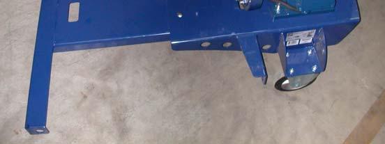
8 RCA 380 E : Connect the RCA 380 E to the thee-phase electric power source: Nominal voltage: 400 V / 50 Hz Minimum Power Cable Size: 4 mm² Plug: 32A-CCE 3P+N+E 400V Nominal Current of the Main Fuses: 32 A Connection Power: 21,2 kw I Warning! Before completing the connection of the machine it is necessary to check the rotating direction of the cutting chain and/or electric motor. Wrong rotating direction can cause damages to the oil pump. II Change the rotating direction of the electric motor by inverting the poles on the plug. 3.1 DISCHARGE CONVEYOR ASSEMBLY (in case of separate delivery) Hydraulically driven discharge conveyor is also a component part of the firewood processor. Place the discharge conveyor on the ground and move it closer to connecting spot Slide the discharge conveyor on the supporting forks and secure it with two screws (1 Figure:3) Fasten the lifting package by fixing rope pulleys to their position (2-Figure: 4). Use the hand winch (3-Figure: 3) to lift the discharge conveyor slightly above the desired height and attach the carrying chain (4-Figure: 3). Loosen the wire rope, so that the weight of discharge conveyor is distributed between the wire rope and carrying chain (4-Figure:3) Connect the hydraulic connectors (a & b) 3 3 a b a b 1 4 8


 must be closed fully tightened.")
9 3.1.1 RETRACTION OF THE DISCHARGE CONVEYOR Discharge conveyor is usually telescopically retracted in the machine transport position. By activating the machine, telescopic cylinder of the discharge conveyor automatically activates and fully extends the machine, so the belt is tensioned. Before starting the machine, make sure to loosen the conveyor belt, by moving the Discharge Conveyor from vertical to horizontal position using the hand winch (3-Figure:3). Otherwise damages to the belt can occur during the extension procedure! To optimally tension the belt, move the control handle of the lifting table (E-Figure: 1) to the lowering position, which increases the system pressure. To position the Discharge Conveyor into the working extended position, the discharge conveyor valve (T:Figure:1) must be closed fully tightened. After you disconnect the machine drive, you can retract the discharge conveyor. Open the discharge conveyor valve (T-Figure: 1) and leave the discharge conveyor to retract by its own weight. Therefore put the machine in more upright position. When the discharge conveyor is retracted, close the discharge conveyor valve (T-Figure: 4). The valve must be also closed during the operation. 4 T 2 t Ensure the clearance t between the nut and the hand winch handle axis. 3.2 TRACTOR PTO SHAFT DRIVE (RCA 380): P.T.O. shaft (grooved shaft 13/8!" Z6 DIN 9611A) must comply with the required driving power of the machine (technical data). The tractor P.T.O. shaft must rotate in a clockwise direction. Recommended rotating speed of the P.T.O. shaft: 420 RPM; maximum: 430 RPM, minimum: 400 RPM 9
10 3.3 STARTING UP: Before each machine startup, it is necessary to check the chain tension and readjust it if necessary! A too loose chain can induce vibrations, which unfavorably affect the drive belt s operation. Increased vibrations can also cause damages to the drive belt. A new cutting chain needs to be retensioned after approx. half an hour of use. Please check. Remove all wood remains and other particles from the splitting chute, before starting the machine! Check the oil levels of the hydraulic system and cutting chain lubrication system, before starting the machine! Before starting the machine, make sure to loosen the conveyor belt, by moving the Discharge Conveyor from vertical to horizontal position using the hand winch (3-Figure:3). Otherwise damages to the belt can occur during the extension procedure! RCA 380 : Examine the machine and equipment for faults and check the chain lubrication Place the tractor manual throttle handle in lowest position. Lift the machine cover (B-Figure: 1a) to activate the safety switch and disengage all major machine functions. Slowly engage the P.T.O. shaft drive and start the machine. Set the required rotating speed of P.T.O. shaft (420 RPM), using the manual throttle handle. Lower the machine cover. RCA 380 E: Examine the machine and equipment for faults and check the chain lubrication Plug the machine to electric power source Turn on the Main Switch (R-Figure: 1) Lift the machine cover (B-Figure: 1) to activate the safety switch and allow easier starting of the electric motor Push the Start-Stop switch (green button) (S-Figure:1) and immediately check the rotating direction of the cutting chain: in case of wrong cutting chain direction, immediately stop the drive (push the red button on the Start-Stop switch and change the rotating direction of the electric motor (Chapter: 3.) Lower the machine cover 10

: RCA 380 RCA 380 E Therefore, it is mandatory to wear")
11 3.4 TRANSPORT POSITION OF THE MACHINE 5a The maximum allowable speed of the tractor when transporting the machine on the rut or offroad is 10 km/h (12 mph) and 40 km/h (25 mph), when the tractor is driven on the asphalt roads! 5b Driving at unsuitable speeds for the road conditions can cause damages to the machine or the tractor. 4 OPERATING THE FIREWOOD PROCESSOR The machine must be operated by one person only. Please ensure that there is nobody else in the near vicinity of the machine working area. 4.1 NOISE Machine operator is exposed to the following noise levels, during the machine operation (measured near the ear of the machine operator): RCA 380 RCA 380 E Therefore, it is mandatory to wear hearing protectors while operating the machine. 4.2 LOG FEEDING The in-feed conveyor must be placed in a horizontal working position before operation of the machine: Idling mode: 87 db (A) 88 db (A) Operation mode: 92 db (A) 96 db (A) Pull out the safety pin (10-Figure:6) Remove the support limiter (12-Figure:6) Lower the in-feed conveyor (A-Figure:6) in horizontal position and support it using the supporting leg (11-Figure:6) Set the supporting leg so that the upper rod on the conveyor belt in the middle of the feed conveyor is slightly elevated above the table (already factory set).. Activate the feeding by pushing the sawbar activation handle (H-Figure: 1) from the upper position (neutral position) forward - away from yourself; you can stop it at any time (when the log reaches length limiter), by returning the handle to the neutral position. In case you don t stop the feeding after the log reaches the length limiter, you can damage the in-feed conveyor belt. The in-feed conveyor can be additionally operated with the handle for setting its rotating direction (D-Figure- 1). Using this handle, the conveyor belt can be activated in either direction. 11


12 A 11 7 H P 12
, during which the sawed log must be held using the retaining handle (P- Figure: 7).")

13 4.3 SAWING The barsaw is always operating. The sawbar movement is performed using the sawbar activation handle (H-Figure: 7), during which the sawed log must be held using the retaining handle (P- Figure: 7). When the sawing begins, the trapdoor (13-Figure:8) moves away automatically, so the log can fall freely into a splitting chute after the cut. Adjust the sawbar moving speed according to the hardness of the wood. Finish the cut (app. last 20 mm - last 1 in ) with rapid downward movement of the sawbar activation handle, to make the cut log fall into the chute correctly. When cutting hard wood, the cut log can fall into the chute and rebound in the air - and splitting cylinder can grab it sideways*, which can cause the jam and even damage to the machine. To avoid this, hold the sawbar activation handle after the cut in lower position, to allow the cut log to correctly position itself in the chute. Only then lift the sawbar activation handle to activate one of the two splitting cylinders. * in this case quickly switch the cylinders or open the machine cover, to stop the splitting cylinder and reposition the cut log. The force on the sawbar activation handle should not exceed 100N. Greater force can cause increased vibrations of the belt, which may result in damage to the belt. Check the tension of the belt (Chapter: 5.9) ADJUSTING THE WOOD LENGTH The length of the firewood is set by adjusting the position of the length limiter (15-Figure:8), which is fixed in the required position using the fixing pin (14-Figure:8) SPLITTING Splitting is performed by a splitting cylinder that pushes the log towards a splitting wedge. The splitting speed depends on the wood resistance and changes during splitting. Since the splitting speed is inversely proportional with the splitting force, the splitting cylinder enables greater splitting force at a lower speed and smaller splitting force at a greater splitting speed. The splitting cylinder automatically selects the necessary speed or splitting force, which results in greater energy efficiency. The activation of splitting cylinder is performed by lifting the sawbar activation handle (H-Figure 1), after the log has been cut or using the cylinder operating handle (C-Figure:9). Cylinder operating handle (C-Figure:9) can also be used at any time, to move the Cylinder Piston to the starting position, which is sometimes required in practice to prevent jamming during the splitting phase. 13


14 9 C S B B ADJUSTING THE HEIGHT OF THE SPLITTING WEDGE 10 L By using a splitting wedge handle (L-Figure: 10), the splitting wedge can be gradually lifted or lowered depending on the diameter of the logs - so the logs are split in center. Splitting wedge adjustment can be performed most easily when the splitting chute is empty or at the point when the splitting cylinder start to move. Lifting mechanism of the splitting wedge also allows partial height movements of the splitting wedge during the splitting phase. In case the wood gets stuck under the splitting wedge it must be removed to prevent damage to the lifting mechanism of the splitting wedge (Refer to chapter 5.11, indications of overload ). 14


15 4.4.2 PROPER USE OF SPLITTING WEDGE To ensure the durability of your splitting wedge, follow these instructions: 1. The splitting wedge is designed exclusively for wood splitting up to the max. diameter specified on your RCA machine. Dmax Dmax 2. The log in the splitting chute must always be longitudinally directed towards the splitting wedge. This prevents unnecessary overloads and downtime. 3. The log in the splitting chute must always be centred on the vertical blade of the splitting wedge. This prevents overloading of the side blades of the splitting wedge. 15


16 4. Ensure that the splitting chute and splitting wedge are never obstructed. Always remove any wedged pieces of wood. 5. Adjust the height of the splitting wedge to be slightly less than the mechanism permits. This allows the splitting wedge to still breathe during the splitting so as not to burden the mechanism and the lower blades of the wedge. 5 min Failure to observe the instructions may result in mechanical damage to the wedge and the machine that is not subject to reclamation MACHINE COVER WITH SAFETY SWITCH In case of eventual problems during the splitting phase, or in case the log is wrongly positioned in the splitting chute, the splitting process must be stopped immediately. In this case it may be also necessary to switch the cylinder, so the splitting cylinder which pushes towards the splitting wedge, moves back (4.4). Machine cover (B-Figure: 11) is linked to the safety switch, which disengages all major machine functions when the machine cover is lifted: in-feed and discharge conveyors stop, splitting cylinder stop and sawbar is withdrawn into the saw shield. Lifting the machine cover therefore acts also as a main safety switch. The log can be reached by hand only when the machine cover is opened and machine is stopped. Sawing and splitting cannot continue until the machine cover is closed and safety switch disengaged. 16

.")


17 11 B STOP START-STOP SWITCH (RCA 380 E) Electrical system of the wood processor RCA 380 E includes, besides the main switch, also the Start-Stop switch (S-Figure: 1). The Start-Stop switch is used to turn ON/OFF the electric driving motor, which powers the cutting chain and whole hydraulic system. Using the red button of the Start-Stop switch you can completely stop the operation of the machine. Before staring the machine or pushing the start-stop switch it is recommended to lift the machine cover, to allow easier starting of the electric motor (Refer to chapter 3.3) MAIN SWITCH (RCA 380 E) The wood processor s main switch (R-Figure: 1b) shuts down the main power supply. Use the main switch when stopping the work for longer periods or leaving the work place. Unauthorized access to the power switch can be prevented by installing the padlock. 4.5 DISCHARGE CONVEYOR K Lifting and lowering of the discharge conveyor is performed with the hand winch handle (23-Figure: 12). When the desired position is reached, secure it with the chain, so that the weight of discharge conveyor is distributed between the wire rope and the carrying chain. (24 Figure: 12). When using and maintaining the hand winch, follow the enclosed manufacturer s instructions. The speed of the discharge conveyor can be adjusted using the speed regulator of the discharge conveyor (K-Figure: 12). 17

! Disconnect the P.T.O.")
 90 degrees on the sawbar activation handle.")
 Unscrew both nuts (34- Figure: 15) on the fixing")


18 5 MAINTENANCE AND REPAIR Regular machine maintenance ensures reliable operation and long lifetime of the machine 5.1 CUTTING CHAIN REPLACEMENT Before replacing the chain, you must disconnect the machine drive (RCA 380) or unplug the power cord from the electrical outlet (RCA 380 E)! Disconnect the P.T.O. shaft or unplug the power cord from the electrical outlet. Turn the handle (28-Figure:13) 90 degrees on the sawbar activation handle. Unscrew the screw (29-Figure:13) and move the saw shield (30- Figure:14) in the forward position. Loosen the cutting chain tensioning screws (33-Figure:15) Unscrew both nuts (34- Figure: 15) on the fixing plate (35- Figure: 15) until you can move the sawbar away from the tensioner. Remove the worn cutting chain and replace it with new well-sharpened chain. Make sure the cutting teeth are turned in the right direction the cutting edge on the top of the sawbar must face the machine controls. Replace the cutting chain in a reverse order and don t forget to tension it afterwards. A new cutting chain must be run-in; 2 to 3 minutes. The cutting chain tension must be rechecked immediately afterwards. (Refer to chapter 5.2) Do not install a new cutting chain on a worn out sprocket. Replace the sprocket after second replacement of the worn out chain at the latest
19 5.2 CUTTING CHAIN TENSIONING Loosen both nuts (34-Figure: 15) on the fixing plate (35-Figure: 15) Tighten the tensioning screw (33-Figure: 15) until the chain in tensioned correctly* Tighten both nuts (34-Figure: 15) on the fixing plate (35-Figure: 15) *The cutting chain is tensioned correctly when it clings to the lower side of the sawbar when cold and can be still lifted on the upper side of the sawbar (approximately in the middle), three or four times the height of the driving teeth. Always wear gloves when checking the chain tension to avoid cutting your fingers on the sharp chain! 5.3 CHANGING THE SPLITTING WEDGE Remove all firewood and wood remains from the splitting wedge area (splitting chute and under the machine). Activate the splitting cylinder and open machine cover when the cylinder reaches the middle position, to make enough room for splitting wedge replacement. Put the handle of the splitting wedge (L-Figure: 16) in the right position, to lower the splitting wedge completely. Remove the splitting wedge from its mount and replace it with a new wedge (39-Figure: 17) Close the machine cover. Set the desired splitting wedge height L HYDRAULIC SYSTEM OIL CHANGE Important: To prevent pollution of the environment, dispose of used oil properly! Perform the first oil change after 5000 hours of operation. Afterwards change the oil every 2 years The oil drain plug is located on the lower side of the tank. Hydraulic system oil quantity: 100 l. / 25 gallons 19


20 Hydraulic oil suitable brands: (Viscosity: 46 mm 2 /s at 40 o C) Manufacturer s: Renolin B 46 - HVI Substitute oils: Castrol Hyspin AVH 46 Mobil DTE 16 Shell TELLUS T46 BIPI Energol SFA 46 SETRAL Poclain 5.5 OIL FILTER MAINTENANCE Check and/or clean the oil filter when the first oil change is performed. Presence of small aluminum particles, caused by running-in of the pump is expected. Clean the filter insert using gasoline. Work in open areas and take necessary precautions to prevent fire. Using an air compressor, blow the filter insert from inside out. Filter insert must be replaced only if the filter gets mechanically damaged. Bad filter permeability is shown on the filter gauge if the gauge indicator is in the red zone when oil is heated to operating temperature. Change the oil filter 5.6 LUBRICATION OF THE ANGLE MULTIPLICATION GEAR (RCA 380) Oil quantity and grade: 1.2 l (0,32 gallon), SAE 75 (Renolin CLP 100 DIN /13) Replace the oil when changing the reduction gear bearings. 5.7 CUTTING CHAIN LUBRICATION Never operate the machine without lubricating the chain first! Chain lubrication oil quantity: 8 L Approximate oil consumption: ( ) L/h Quality chain lubrication oils with viscosity grade of 95 mm 2 /s at 40ºC are recommended. 18 Never use used oils! The flow of the cutting chain lubrication oil can be regulated depending on the oil quality, using a regulation screw (Figure: 18). It is factory set to maximum! 20
21 5.8 TROUBLESHOOTING PROBLEM POSSIBLE CAUSES SOLUTION The machine does not react to movements of the sawbar activation handle Electric motor does not start or it often shuts down (RCA 380 E) Damaged control mechanism Damages to power cables or blown fuses Motor protection is shutting the motor down. Check the machine drive (P.T.O. shaft or electric motor must be connected and in operation, otherwise the pump and chainsaw drive do not work) Check the level of the oil in the tank Repair or replace the control mechanism Check the power cables, install the approp- Power cable size is not appropriate, the machine is overloaded Hydraulic oil is overheating Not enough oil in the reservoir Check the oil level and add more if necessary. Worn-out hydraulic oil Change the hydraulic system oil. Clogged oil filter Clean the oil filter. (5.5) Clogged hydraulic pipes Splitting cylinder did not reach the final position. Check the hydraulic pipes and clean them if necessary. Reverse the cylinders, clean the splitting chute High Outside Temperature Install the oil cooler Machine is loosing power Hydraulic oil is overheating Refer to Hydraulic oil is overheating Excessive power consumption during sawing Louder operation of the machine Not enough oil in the reservoir The machine is overloaded The chain is dull The chain is not properly tensioned The chain is covered with resin Revolution speed of the tractor is exceeded (RCA 380) Clogged filter Not enough oil in the reduction gear Check the oil level and add more if Remove the overloading causes Sharpen or replace the chain Tension the chain Clean the chain using the solvent (i.e. Nitro-Solvent) or replace the chain Consider the recommended revolution speed. Clean the filter Check the oil level and add more if necessary. The machine is not connected to the tractor only P.T.O. shaft is connected (RCA 380) P.T.O. shaft is not lubricated Connect the machine to the tractor or position the tractor perpendicular to machine Lubricate P.T.O. shaft appropriately Hydraulic hoses are overheating Not enough oil in the hydraulic system Check the oil level and add more if necessary. Worn-out hydraulic oil Replace the hydraulic system oil. (**) Hydraulic cylinder is leaking Seals are worn-out Replace worn-out seals. In-feed conveyor is slipping or not operating Damaged piston-rod Conveyor belt is not tensioned enough Not enough oil in the hydraulic system Replace the cylinder Tension the conveyor belt Check the oil level and add more if necessary. 21
22 PROBLEM POSSIBLE CAUSES SOLUTION In-feed conveyor is not generating enough pull, although low pressure gauge shows 90 bars during its operation. The chain is not lubricating Conveyor belt is not tensioned enough Incorrect installation of the conveyor belt The log too heavy or jammed The machine ran out of chain lubrication oil Lubrication system is clogged or damaged Tension the in-feed conveyor belt Check the placement of the supporting foot (Chapter.:4-2) Add chain lubrication oil Check the lubrication system Discharge conveyor is not operating Conveyor belt is not tensioned enough Tension the conveyor belt Not enough oil in the hydraulic system Check the oil level and add more if necessary Speed regulator is fully screwed down Position or cut the log shorten the log Set the speed regulator appropriately Torn cutting chain drive belt Inappropriate rotating speed of the P.T.O. shaft + worn cutting chain More demanding procedures must be performed by a qualified technical service only. (**) In worse operating conditions with high temperatures of the environment we recommend installation of oil cooler. 5.9 MAINTENANCE PLAN Stuck wood is preventing the conveyor belt from moving. 22 Replace the belt (5.10), replace the cutting chain (5.1). Increase the rotating speed of the P.T.O. shaft (3.2). Cutting chain is not properly tensioned Replace the belt (5.10), tension the cutting chain properly (5.2) Belt is not properly tensioned Replace the belt (5.10) Excessive force on the operating handle during cutting Clean the conveyor belt area stop the machine during cleaning procedure. Replace the belt (5.10), (4.3), check the cutting chain and use lower force on the operating handle. The machine must be turned off (the P.T.O. shaft must be disconnected from the tractor), while performing any service and maintenance procedures! WHAT? WHEN? HOW? Check the tension of the cutting chain Before each use 5.2. Check the tension of the cutting chain belt Tighten any loose bolts and nuts and hydraulic connections Check the oil level (hydraulic & bar oil levels) Hydraulic system oil change Cleaning the oil filter Multiplication gear oil change (RCA 380) Cleaning and replacing the air filter on the saw drive Every 50 hours of operation After first hour of operation After every 100 hours of operation Before each use First after 5000 hours of operation, afterwards once every two years During the oil change or in case the gauge indicator is in the red zone After the first 50 hours of operation Later, after every 1000 hours of operation Cleaning the filter - daily Replacing the filter - every 6 months Using appropriate tools visually 5.4 Clean the filter with gasoline and blow it with compressed air from inside out. Drain the oil in the appropriate vessel from the lowest plug and replace the plug. Fill the oil through the upper plug Regularly remove all wood remains and sawdust from the splitting channel, under the conveyor belt, under the lifting mechanism of the Splitting Wedge and under Sawbar Activation Handle!
")


23 c 19 d b a WHAT? WHEN? HOW? Lubrication (Figure:19) Lubrication Point: a, b, c At least every 80 hours of operation Lithium Grease Lubrication Point: d At least every 80 hours of operation Lubricating Spray 23


 Remove the lubrication")
 Remove")
 Remove")


, housing cover (42")
 After one hour test operation,")


24 5.10 CUTTING CHAIN BELT REPLACEMENT Disconnect the machine from the drive or unplug the power cord from the electrical outlet Remove the drive protection (41 Figure: 22), remove the housing cover (42 Figure: 22), remove the drive cover (43 Figure: 22) Remove the lubrication pump (44 Figure: 22) Loosen the belt tensioner (45- Figure: 22) Remove the belt (46 Figure:22) from the driven pulley (47 Figure: 22) Remove the old belt and clean the area Install the new belt Position the belt onto the pulleys. Tension the belt and reinstall removed elements: lubrication pump (44 Figure: 22), drive protection (41 Figure: 22), housing cover (42 Figure:22), drive cover (43 Figure: 22) After one hour test operation, recheck the tension of the belt (disconnect the machine from the drive). Perform additional tension controls every 50 hours of operation. 22 a c e b d f

 Screw or unscrew the spring")
25 BELT TENSIONING The machine must be stopped, during the operation! Set the correct tension of the belt using the notch on the tension indicator. The notch must be aligned with the edge of the spring guide. Set the tension of the belt as follows: Loosen the safety nut (47-Figure: 23) Screw or unscrew the spring guide, as appropriate (48-Figure: 23) and correctly align the notch Tighten the safety nut (47-Figure: 23)
.")
26 CLEANING AND REPLACING THE AIR FILTER FILTER REPLACEMENT Disconnect the machine from the drive Remove the drive protection Remove the drive cover, the hydraulic tube, and the spring screws Replace the filter with a new one, clean the interior, and reattach the drive cover Tighten the spring screws and secure them with the adhesive LOCTITE 222 (or similar). Pay attention to distance X, which should be between 16 and 17 mm. The distance for all three screws must be THE SAME LENGTH. Attention! If the spring is completely compressed, the clutch will not work X Tighten the hydraulic tube and, finally, secure the drive protection CLEANING THE FILTER Remove sawdust and waste from the top of the filter (the cover) to allow free air flow to the inside of the saw drive. Regularly clean and change the filter on the saw drive. An unclean filter impedes the cooling air flow to the drive assembly, which may result in overheating or damage to the drive assembly (bearings, belt, shaft ). 26
27 5.11 INDICATIONS OF IMPROPER USE Certain damages which occur before the end of the lifespan of exposed machine components may indicate overloading or inappropriate handling of the machine. Manufacturer s warranty does not cover damages of this kind. Torn or damaged in-feed or discharge conveyor belts Torn cutting chain Damaged chain guide (sawbar) Damaged or bent framework, wedge or cylinder protection Damaged or bent length limiter or trapdoor Torn cutting chain drive belt Damages to the operating handles Damages to the framework due to unsuitable transport Damaged hand winch on the conveyor Damaged carrying chain carabiner Damaged wedge holder Damaged or broken splitting wedge Clogged or damaged air filter Important: The machine is functionally and safety tested. To ensure flawless and safe operation it is necessary to use only original spare parts in case of breakdown. The customer looses all claims of warranty if non-original spare parts are used, if repairs are performed unprofessionally or by unqualified person or in case of any modifications to the machine SUPPLIES The machine incorporates following parts, which have to be replaced by the customer as necessary. These parts are not covered by the warranty period, which is defined in the warranty statement. Cutting chain Drive chainwheel Cutting chain guide (sawbar) Cutting chain drive belt Electric motor driven belt Conveyor wire rope In-feed conveyor belt Discharge conveyor belt Splitting wedge Oil Air filter 5.13 SPARE PARTS ORDERING When ordering spare parts it is necessary to provide the following information: Model and serial number of the machine; catalogue number, name and quantity of the spare part; Exact address of the customer The manufacturer warrants spare parts availability and service 10 years after the purchase of the machine 27
28 EC Declaration of Conformity Manufacturer: TAJFUN Planina, proizvodnja strojev d.o.o., Planina 41a, 3225 Planina pri Sevnici declares with full responsibility that hereinafter mentioned product: FIREWOOD PROCESSOR RCA 380 covered by this declaration complies with the requirements of: Directive 2006/42/EC and is in compliance with harmonized standards: EN ISO :2009; EN ISO 12100:2010; EN ISO 13857:2008; EN 349:1993+A1:2008; EN A2:2009; ISO 4413:2010 Authorized person for technical documentation: Iztok Špan, Planina 41a, SI-3225 Planina pri Sevnici Planina, Iztok Špan General Manager 28

29 EC Declaration of Conformity Manufacturer: TAJFUN Planina, proizvodnja strojev d.o.o., Planina 41a, 3225 Planina pri Sevnici declares with full responsibility that hereinafter mentioned product: FIREWOOD PROCESSOR RCA 380 E covered by this declaration complies with the requirements of: Directive 2006/42/EC Directive 2004/108/EC Directive 2006/95/EC and is in compliance with harmonized standards: EN ISO :2009; EN ISO 12100:2010; EN ISO 13857:2008; EN 349:1993+A1:2008; EN A2:2009; ISO 4413:2010 Authorized person for technical documentation: Iztok Špan, Planina 41a, SI-3225 Planina pri Sevnici Planina, Iztok Špan General Manager 29
30 30
31 31
32 WARRANTY SHEET We guaranty: that the product will operate fault free, if operated according to enclosed operating instructions; that we will repair any fault or defectiveness during the warranty period, within 45 days. In case the product is not repaired within the mentioned term, we will replace it with a new product on customer s request. The product is warranted 12 MONTHS from the day of purchase, which must be proved by the customer with the certified warranty sheet (stamp of the shop, date of purchase and salesman s signature, serial number and year of manufacture). Guarantee sheet is valid only if shown together with original invoice! The warranty covers parts against defects in material and workmanship. In case of repairs performed by unqualified person or if non-original spare parts were used, the customer looses all claims of warranty! Our guaranty is void also in case of: Damages caused by not following these operating instructions Damages which are customer s fault Damages resulting from improper use or overload and operation in unsuitable conditions Product specifications (copy from the type plate): Type: Serial no.: Year of manufacture: Data on product sale: STORE (company and headquarters): Date of delivery: Stamp and signature of the salesperson: 32
AU DU PONT DE LUTTRE BRUSSELS BELGIUM PHONE: FAX: OPERATING MANUAL. Electric Fully Automatic Floor Saw FS 1218 EX
 AU DU PONT DE LUTTRE 74-1190 BRUSSELS BELGIUM PHONE: 322 34 83 162 FAX: 322 34 83 136 OPERATING MANUAL Electric Fully Automatic Floor Saw FS 1218 EX 2 Important information before you start! When the machine
PRODUCT CATALOGUE. Firewood Processors - RCA Logging Winches Tractor crane TajGO Forestry Information System
 PRODUCT CATALOGUE Firewood Processors - RCA Logging Winches Tractor crane TajGO Forestry Information System Tajfun Planina d.o.o., founded in 1967, provides complete and integrated solutions in the field
Instructions for use. FORESTRY WINCHES 65H / 85H / 65Hpro / 85 Hpro. Instructions for safe work Spare parts list
 Manufacturer: d.o.o. Dobriša vas 14/a 3301 PETROVČE SLOVENIA TEL.: +386 3 713 14 10 info@uniforest.si Instructions for use FORESTRY WINCHES 65H / 85H / 65Hpro / 85 Hpro Instructions for safe work Spare
EU DECLARATION CONFORMANCE
 LOGIFLEX ELF / ELFS EU DECLARATION CONFORMANCE Manufacturer: Logitrans A/S Hillerupvej 35 DK-6760 Ribe Denmark It is hereby declared that: Machine: Productgroup: Logiflex Type: ELF/ELFS Year of manufacture/
Finishing Mower Estate 72
 Finishing Mower Estate 72 Owners/Operators Manual & Spare Parts List Issue Date: October 2011 1 Introduction Your FIELDMASTER Estate 72 Finishing Mower has been designed to do a range of work to your satisfaction.
Firewood Processor Operator s Manual SSA400Z
 Distribution Limited Firewood Processor Operator s Manual SSA400Z FOR YOUR SAFETY READ AND UNDERSTAND THE ENTIRE MANUAL BEFORE OPERATING THIS MACHINE Warranty Registration Form Model: Serial Number: Type
Wood Chipper Model C550M Operator's Manual
 Wood Chipper Model C550M Operator's Manual THIS MANUAL MUST BE READ AND UNDERSTOOD BEFORE ANYONE OPERATES THIS MACHINE! Manual# 990023 Revised 01/2010 YOU MUST FILL OUT YOUR WARRANTY REGISTRATION TO ACTIVATE
Instructions for use FORESTRY WINCH 65M/85M. Instructions for safe work Spare parts list
 Manufacturer: d. o. o. SI-3301 PETROVČE Tel.: 00386/3777 14 10 E-mail: info@uniforest.si Instructions for use FORESTRY WINCH 65M/85M Instructions for safe work Spare parts list 1 GENERAL Dear customer!
These operating instructions apply for: NCX 380 NCZ 300 NCX 480 NCZ 370 NCX 580 L NCZ 480 NCX 660 K NCZ 560 NCZ 660 NCZ 800
 Original instructions Operating Instructions for May 2010 Electric Internal Vibrators BA No. 1092E Series NCX and NCZ These operating instructions apply for: NCX 380 NCZ 300 NCX 480 NCZ 370 NCX 580 L NCZ
Demco. Model E Bedienungsanleitung Instruction manual Mode d emploi Istruzioni d uso Instrucciones para el servicio Инструкция по эксплуатации
 Demco Model E96-230 Bedienungsanleitung Instruction manual Mode d emploi Istruzioni d uso Instrucciones para el servicio Инструкция по эксплуатации Manufactured by: CMP Industries LLC 413 N. Pearl St.
SIP Direct Drive Oil-Lube Air Compressors - Operating & Maintenance Instructions
 SIP Direct Drive Oil-Lube Air Compressors - Operating & Maintenance Instructions Please read and fully understand the instructions in this manual before operation. Keep this manual safe for future reference.
Hydraulic Breakers HH35. Prior to Operation. From Serial No Revised We thank you for choosing a HYCON breaker.
 Hydraulic Breakers HH35 From Serial No. 12263 Revised 01.02.2015 Prior to Operation We thank you for choosing a HYCON breaker. To ensure smooth operation and long-lasting performance of your new breaker,
Maintenance and Repair
 Maintenance and Repair WARNING ALWAYS shut off the engine, remove key from ignition, make sure the engine is cool, and disconnect the spark plug and positive battery terminal from the battery before cleaning,
WOOD CHIPPER WC1103 5PQ (8/02/12)
") O P E R A T O R ' S M A N U A L WOOD CHIPPER WC1103 5PQ990101 (8/02/12) To the Owner; Thank-You for choosing a quality product from Frontier Equipment. We strive to give you the best equipment and the
O P E R A T O R ' S M A N U A L WOOD CHIPPER WC1103 5PQ990101 (8/02/12) To the Owner; Thank-You for choosing a quality product from Frontier Equipment. We strive to give you the best equipment and the
LOG SPLITTER. Heavy Duty PTO Driven. Owners Illustrated Instruction Book & Parts List
 LOG SPLITTER Heavy Duty PTO Driven Owners Illustrated Instruction Book & Parts List Grovebury Road, Leighton Buzzard, Bedfordshire. LU7 4UX. UK. Tel:01525 375157. Fax:01525 385222. Email: enquires@brownsagricultural.co.uk
DYNAPAC CONCRETE EQUIPMENT RAMIRENT. BG70 Power Floats INSTRUCTIONS & SPARE PARTS CATALOGUE BG70 - IS ENG
 DYNAPAC CONCRETE EQUIPMENT INSTRUCTIONS & SPARE PARTS CATALOGUE BG70 Power Floats BG70 - IS - 10682 - ENG SAFETY INSTRUCTIONS - MACHINES SUBMITTED : Powered with : Electric, Pneumatic, Petrol or Diesel
OPERATION AND MAINTENANCE MANUAL SERIES HIGH GRASS MOWER FT
 S.p.A. OPERATION AND MAINTENANCE MANUAL SERIES HIGH GRASS MOWER www.hscmsc.co.uk CONTENTS INTRODUCTION IDENTIFICATION AND TECHNICAL CHARACTERISTICS PACKING AND TRANSPORT SAFETY RULES AND LIMITS ON USE
LOG CHOP. Hydraulic Wood Guillotine. Owners Illustrated Instruction Book & Parts List
 LOG CHOP Hydraulic Wood Guillotine Owners Illustrated Instruction Book & Parts List Grovebury Road, Leighton Buzzard, Bedfordshire. LU7 4UX. UK. Tel:01525 375157. Fax:01525 385222. Email: enquires@brownsagricultural.co.uk
Portable Electric/Gas Compressor Operating Instructions
 Portable Electric/Gas Compressor Operating Instructions NOTICE Carefully read this instruction manual before attempting to operate this compressor. MODEL # SERIAL # 1-800-551-2406 TABLE OF CONTENTS Safety
WOOD CHIPPER WC1105 5PQ (8/08/2012)
") O P E R A T O R ' S M A N U A L WOOD CHIPPER WC1105 5PQ990102 (8/08/2012) To the Owner; Thank-You for choosing a quality product from Frontier Equipment. We strive to give you the best equipment and the
O P E R A T O R ' S M A N U A L WOOD CHIPPER WC1105 5PQ990102 (8/08/2012) To the Owner; Thank-You for choosing a quality product from Frontier Equipment. We strive to give you the best equipment and the
Maximum Flow: 600 GPM (3800 LPM) Portable Base 1250 GPM (4800 LPM) Direct Mount. Maximum Pressure: 200 PSI (1380 Kpa, 13.8 BARS)
 Portable Base 1250 GPM (4800 LPM) Direct Mount. Maximum Pressure: 200 PSI (1380 Kpa, 13.8 BARS)") STYLE 3414 Apollo S.I. Monitor with FoldING Legs OPERATING & MAINTENANCE INSTRUCTIONS WITH SPECIAL L.A. COUNTY SPECIFICATIONS The Akron Style 3414 Apollo Monitor is designed to provide efficient trouble-free
STYLE 3414 Apollo S.I. Monitor with FoldING Legs OPERATING & MAINTENANCE INSTRUCTIONS WITH SPECIAL L.A. COUNTY SPECIFICATIONS The Akron Style 3414 Apollo Monitor is designed to provide efficient trouble-free
: 1250 gpm in the deck mode : 800 gpm while operating in the ground base - Dual Inlet : 1000 gpm while operating in the ground base - Single Inlet
 APOLLO HI-RISER MONITOR STYLE 3433/3431 INSTALLATION, OPERATING, AND MAINTENANCE INSTRUCTIONS The following is intended to provide the basic instructions for installation, operation and maintenance of
Original operating manual
 matev GmbH Nürnberger Str. 50 90579 Langenzenn T +49 9101 9087-0 F +49 9101 9087-20 info@matev.eu www.matev.eu Original operating manual Engine PTO Shaft FPS-PTO JD-3R for John Deere, type 3033R, 3038R,
RINK Model 1622 Series number:
 OPERATION MANUAL AND LIST OF PARTS RINK Model 1622 Series number: WARNING: IN ORDER TO ENSURE SAFE USE OF THE MACHINE AND OPTIMAL RESULTS, IT IS ESSENTIAL TO READ THIS OPERATION MANUAL CAREFULLY BEFORE
REEL ROTATOR SELFRRM/SELFSRRM, SELFRRE/SELFSRRE
 REEL ROTATOR SELFRRM/SELFSRRM, SELFRRE/SELFSRRE EU DECLARATION CONFORMANCE Manufacturer: Logitrans A/S Hillerupvej 35 DK-6760 Ribe Denmark It is hereby declared that: Machine: Productgroup: Reel Rotator
TAJFUN PRODUCT CATALOGUE. Firewood Processors - RCA Logging Winches Tractor crane TajGO Forestry Information System
 TAJFUN PRODUCT CATALOGUE Firewood Processors - RCA Logging Winches Tractor crane TajGO Forestry Information System Tajfun Planina d.o.o., founded in 1967, provides complete and integrated solutions in
US - UP2/OIL 12V US - UP2/OIL 24V
 SELF PRIMING ELECTRIC PUMP FOR TRANSFERRING LUBRICATING OILS OR VISCOUS FLUIDS INSTRUCTIONS FOR USE 164 220 12-US - UP2/OIL 12V 164 220 13-US - UP2/OIL 24V 15/05/14 Rev.02 A PRODUCT DESCRIPTION Self-priming
Hydraulic Impact Wrench Type
 M a s c h i n e n f a b r i k G m b H Hydraulic Impact Wrench Type 6 1520 0010 Illustration can differ from the original Operation and Maintenance Manual 615200010_en_Version_03 Page 1 of 19 TECHNICAL
Howard Tarmac Sweeper HTS
 2 Howard Tarmac Sweeper HTS Serial Number The Serial and Model numbers are stamped on the frame of your TARMAC SWEEPER. For future reference record the numbers. ALWAYS quote them when ordering spareparts.
Matala. VersiFlow Series. Instruction and Maintenance Manual
 VersiFlow Series High Flow Multi-Purpose "Versatile " Pump V-3200 1/5HP 150W / Discharge 2 V-3900 1/3HP 250W / Discharge 2 V-4700 1/2HP 400W / Discharge 2 V-5600 1HP 750W / Discharge 2 Instruction and
GL Ludemann Y-Strainers
 GL Ludemann Y-Strainers Installation, Operation and Maintenance Manual English Issue 1-03/2014 - Page 1/7 GENERAL These instructions are for installing, operation and maintenance of Y-strainers fabricated
Accessories for Wind Power Inverter WINDY BOY PROTECTION BOX 400 / 500 / 600
 Accessories for Wind Power Inverter WINDY BOY PROTECTION BOX 400 / 500 / 600 Installation Guide WBP-Box-IEN103320 IMEN-WBP-BOX Version 2.0 EN SMA Solar Technology AG Table of Contents Table of Contents
Instruction Sheet. 1/2 HP Portable Electric Pumps SAFETY FIRST. L2062 Rev. F 02/ IMPORTANT RECEIVING INSTRUCTIONS 2.
 Instruction Sheet 1/2 HP Portable Electric Pumps L2062 Rev. F 02/12 Index: English:...................................... 1-7 Français:.................................... 8-14 Deutsch:...................................
TABLE OF CONTENTS. Warranty Disclaimers Delivery Checklist After Sale Checklist Safety Set Up... 8
 TABLE OF CONTENTS Pickett Equipment Warranty... 2 Warranty Disclaimers... 3 Delivery Checklist... 4 After Sale Checklist... 4 Safety... 5-7 Set Up... 8 Machine Adjustments and Operation... 9 Maintenance
 Operation and Maintenance Manual Model.75,, 3, 5, 8, 0, 0, 5, 35, 50 http://www.torsionx.com Use the MaxDrv Series Square Drive Torque Wrench Model.75,, 3, 5, 8, 0, 0, 5, 35, 50 to install and remove threaded
ATV TRACK KIT. Operator s Manual Installation Instructions Service Instructions Replacement Parts List. Effective Date: October, 2012
 p/n 2258-642 ATV TRACK KIT Operator s Manual Installation Instructions Service Instructions Replacement Parts List Track Assembly Kits (p/n 1436-204) Mounting Assembly Kits (p/n 1436-205) 1436-815) Effective
WARM ENGINE STARTING PROCEDURE
 saw starting COLD ENGINE STARTING PROCEDURE 1. Pull the choke lever out. 2. Lock the throttle in the start position by depressing and holding the throttle lock button (C) while releasing the trigger (A)
3 Ton Trolley Jack. Please read and fully understand the instructions in this manual before operation. Keep this manual safe for future reference.
 Please dispose of packaging for the product in a responsible manner. It is suitable for recycling. Help to protect the environment, take the packaging to the local amenity tip and place into the appropriate
Start Up & Troubleshooting Manual. Resfab Equipment Inc. St Jean Sur Richelieu Website: resfab.com
 Start Up & Troubleshooting Manual Resfab Equipment Inc. 725 Rossiter St Jean Sur Richelieu 1 450 359 0800 Website: resfab.com Yogurt Blender Service Manual Page SECTION 1: Start Up and Repair... 3 thru
INSTRUCTION MANUAL INDUSTRIAL PERISTALTIC PUMPS MODEL RBT-70
 INSTRUCTION MANUAL INDUSTRIAL PERISTALTIC PUMPS MODEL RBT-70 This manual forms an integral part of the pump and must accompany it until its demolition. The series FMP peristaltic pump is a machine destined
1/4 Die Grinder. Please read and fully understand the instructions in this manual before operation. Keep this manual safe for future reference
 Please dispose of packaging for the product in a responsible manner. It is suitable for recycling. Help to protect the environment, take the packaging to the local amenity tip and place into the appropriate
R E A D T H I S F I RST SAW USER GUIDE MODEL SVC4
 READ THIS FIRST SAW USER GUIDE MODEL SVC4 USER GUIDE This manual covers the description, cautions, operation, and maintenance of the Super Vac SV3. Please take the time to read this manual before operating
Not for Reproduction. BILLY GOAT AERATOR Owner's Manual AE401, AE401H, AE401H5T Replacement Parts. AE Owner s Manual TINE ROW KIT TINE KIT P/N
 BILLY GOAT AERATOR Owner's Manual AE401, AE401H, AE401H5T Replacement Parts TINE ROW KIT Complete tine row set for replacement of one complete row of tines. Includes mounting plates, spacer, and all hardware.
6L Oil-less Air Compressor 53103
 6L Oil-less Air Compressor 53103 Operating Instructions Please read and save these instructions before attempting to assemble, install, operate or maintain the product. Protect yourself and others by observing
 Operation and Maintenance Manual http://www.torsionx.eu Use the MaxDrv Series Square Drive Torque Wrench Model.75, 1, 3, 5, 8, 10, 20, 25, 35, 50 to install and remove threaded fasteners requiring precise
Safety, Operation and Maintenance Instructions For Long & Short Nose Upholstery Air Stapler (NS10 & NS11)
") Safety, Operation and Maintenance Instructions For Long & Short Nose Upholstery Air Stapler (NS10 & NS11) Important: Drop 3 drops of oil into the stapler air inlet BEFORE first use. See page 2. Please
Safety, Operation and Maintenance Instructions For Long & Short Nose Upholstery Air Stapler (NS10 & NS11) Important: Drop 3 drops of oil into the stapler air inlet BEFORE first use. See page 2. Please
User Guide. Lubricus Lubrication System LUB-D1/LUB-D2/LUB-D3/LUB-D4 (24 VDC)
") User Guide Lubricus Lubrication System LUB-D1/LUB-D2/LUB-D3/LUB-D4 (24 VDC) version 04/2013 Content General Information 3 Warning 3 Scope of Supply 3 Overview 3 General safety details 4 Intended use 4
User Guide Lubricus Lubrication System LUB-D1/LUB-D2/LUB-D3/LUB-D4 (24 VDC) version 04/2013 Content General Information 3 Warning 3 Scope of Supply 3 Overview 3 General safety details 4 Intended use 4
CALIFORNIA TRIMMER MOWER MAINTENANCE MANUAL
 CALIFORNIA TRIMMER MOWER MAINTENANCE MANUAL 2 Table of Contents Section 1: General Information Page Handle Assembly Instructions 4 Maintenance All Models 6 Oil Change Procedures All Models 9 Height Adjustment
HH10/HH10RV Hydraulic Breaker
 Prior to Operation HH10/HH10RV Hydraulic Breaker HH10 from serial No. 1451 HH10RV from serial No. 2741 Revised 30.08.2011 We thank you for choosing a HYCON breaker. To ensure smooth operation and long-lasting
Heavy Duty Miniature Quick-Change Applicator (End-Feed Type) with Mechanical or Air-Feed Systems
 with Mechanical or Air-Feed Systems") Heavy Duty Miniature Quick-Change Applicator (End-Feed Type) with Mechanical or Air-Feed Systems Instruction Sheet 408-8039 02 JUN 16 Rev G Ram Post Wire Disc Insulation Disc Insulation Crimper Stripper
Heavy Duty Miniature Quick-Change Applicator (End-Feed Type) with Mechanical or Air-Feed Systems Instruction Sheet 408-8039 02 JUN 16 Rev G Ram Post Wire Disc Insulation Disc Insulation Crimper Stripper
User s Manual and Operating Instructions
 User s Manual and Operating Instructions Model Numbers: CL-36-BDF-A, CL-42-BDF-A, CL-48-BDF-A E355088 READ AND SAVE THESE INSTRUCTIONS IMPORTANT: Read and understand all of the instructions in this manual
FTFR Maintenance and Parts Manual SQ-1 FLOOR TRUSS FINISH ROLLER. Operators Manual
 FTFR Maintenance and Parts Manual SQ-1 FLOOR TRUSS FINISH ROLLER Operators Manual FOREWORD This manual explains the proper maintenance of Square 1 Design Floor Truss Finish Roller as well as the daily
HPD Hydraulic Post Driver
 HPD Hydraulic Post Driver From serial No. 7600 Revised 04.01.2013 Prior to Operation We thank you for choosing a HYCON Post Driver. To ensure smooth operation and long-lasting performance of your new post
VBK 2596/12E/RSF. Thickness and Width Gauge for Strip and Profile. Operating- & Service Instructions. (with lateral guide rollers)
") Thickness and Width Gauge for Strip and Profile (with lateral guide rollers) VBK 2596/12E/RSF Operating- & Service Instructions erstellt am 5.2.1998 freigegeben am Bemerkungen Rev.01 Seiten:16 Name: Rietdorf
Thickness and Width Gauge for Strip and Profile (with lateral guide rollers) VBK 2596/12E/RSF Operating- & Service Instructions erstellt am 5.2.1998 freigegeben am Bemerkungen Rev.01 Seiten:16 Name: Rietdorf
DIAMOND CONCRETE SAW MODEL CC1800XL P R O D U C T S OPERATOR S MANUAL. February Part #
 DIAMOND P R O D U C T S OPERATOR S MANUAL CONCRETE SAW MODEL CC1800XL February 2007 Part #1801038 Intentionally Blank GENERAL SAFETY WARNINGS AND PRECAUTIONS PERSONAL SAFETY Read and understand all operating
Spa USE AND MAINTENANCE CULTIVATOR MODEL BL300 / BL350
 Spa USE AND MAINTENANCE CULTIVATOR MODEL BL300 / BL350 02/12/2008 INDEX INTRODUCTION TECHNICAL DETAILS GENERAL SAFETY REGULATIONS STARTING AND STOPPING USE AND ADJUSTMENT SERVICING TESTS FOR CE REGULATIONS
HYDRAULIC PALLET TRUCK MODEL NO: PT540M/BM/CM & PT685BM/CM PART NO: , , , ,
 HYDRAULIC PALLET TRUCK MODEL NO: PT540M/BM/CM & PT685BM/CM PART NO: 7631700, 7631705, 7631710, 7631715, 7631720 OPERATION & MAINTENANCE INSTRUCTIONS LS0316 INTRODUCTION Thank you for purchasing this CLARKE
50 Gallon Skid Sprayer
 50 Gallon Skid Sprayer Model #: KS50P5 User Manual Read this manual for complete instructions Model #: KS50P5 Table of Contents Warranty... 3 General Safety Information... 3 Hazardous Substance Alert...
Instructions for Fitting, Operating and Maintenance Canopy Door RE / (St.: )
") EN Instructions for Fitting, Operating and Maintenance Canopy Door 1 818 012 RE / (St.: 12.2010) 12.2010 ENGLISH Contents 1 Safety Instructions... 3 1.1 Qualified persons... 3 1.2 Symbols and signal words
EN Instructions for Fitting, Operating and Maintenance Canopy Door 1 818 012 RE / (St.: 12.2010) 12.2010 ENGLISH Contents 1 Safety Instructions... 3 1.1 Qualified persons... 3 1.2 Symbols and signal words
HCS14/16/18 Hydraulic Cut-off Saw. Prior to Operation. We thank you for choosing a HYCON cut-off saw.
 Prior to Operation HCS14/16/18 Hydraulic Cut-off Saw From serial No. 0164 Revised September 2003 HYCON A/S Vester Hassingvej 33 DK-9320 Hjallerup Denmark Tel: +45 9647 5200 Fax: +45 9647 5201 Mail hycon@hycon.dk
RED23305 Owner s Manual
 RED23305 Owner s Manual 5 foot, 3-Point Mounted Snow Blower 270 West Park Avenue Huron, SD 57350 866-526-5682 Serial Number: Date of Purchase: Red Devil Snow Blower See Figure 1. 1. The Red Devil Snow
USE AND MAINTENANCE MANUAL
 LATERAL TURNOVER 360 ORIGINAL INSTRUCTIONS INTRODUCTION This manual includes instructions for assembly, maintenance (regular and extraordinary), and for possible faults with remedies. The instructions
IBT Series Square Drive Torque Wrenches
 IBT Series Square Drive Torque Wrenches Operation and Maintenance Manual Model.75, 1, 3, 5, 8, 10, 20, 25, 35, 50 http://www.torsionx.com Use the IBT Series Square Drive Torque Wrenches Model.75, 1, 3,
FIREWOOD PROCESSORS. WP200 Series Tractor PRODUCT FEATURES
 FIREWOOD PROCESSORS WP200 Series Tractor PRODUCT FEATURES Auto Cycle Ergonomic Controls Adjustable 4-Way Wedge Adjustable Exit Chute Cylinder Cover Adjustable Log Length Guide WP240 25 24" $9,571 Split
Z Master. 62 Mower. for Z Master Z 255 Traction Unit. Model No & UP. Operator s Manual
 FORM NO. 9 88 Z Master 6 Mower for Z Master Z 55 Traction Unit Model No. 7408 89000 & UP Operator s Manual IMPORTANT: Read this manual carefully. It contains information about your safety and the safety
Printed: Doc-Nr: PUB / / 000 / 00
 ORIGINAL OPERATING INSTRUCTIONS Hilti HTE-P 33 dispenser It is essential that the operating instructions are read before the tool is operated for the first time. Always keep these operating instructions
PNL-MS Belt Conveyor with Metal Detector
 PNL-MS Belt Conveyor with Metal Detector Date: Apr, 2013 Version: Ver.B (English) Contents 1. General Description... 7 1.1 Coding Principle... 8 1.2 Features:... 8 1.2.1 Specifications Table... 10 1.2.2
Champion Chippers OPERATOR S MANUAL. Operation & Safety. Includes Model: CX850 CX851. Part #
 OPERATOR S MANUAL Champion Chippers Operation & Safety Includes Model: CX850 CX851 Part # 990026 YOU MUST FILL OUT YOUR WARRANTY REGISTRATION TO ACTIVATE YOUR WARRANTY AND TO QUALIFY FOR PARTS SERVICE!!
Heavy Duty Engine Cranes
 Heavy Duty Engine Cranes Operating Instructions & Parts Manual Model Number Atd-7484 Atd-7485 (Foldable Legs) Capacity 2 Ton 2 Ton Model Atd-7484 Model Atd-7485 Atd Tools Inc. 160 Enterprise Drive, Wentzville,
HYDRAULIC PALLET TRUCKS
 HYDRAULIC PALLET TRUCKS HYDRAULIC PALLET TRUCKS MODEL Nos: PT550 GAL & PT685 GAL PART Nos: 7630234 & 7630236 OPERATION & MAINTENANCE INSTRUCTIONS 0204 Please read these instructions carefully before operating
GARDEN HOSE UTILITY PUMP
 GARDEN HOSE UTILITY PUMP MODEL #HPP360, HPP12V, 473707 MODEL #HPP360, 473707 MODEL #HPP12V ATTACH YOUR RECEIPT HERE Purchase Date SAFETY INFORMATION Please read and understand this entire manual before
TIRE GROOVER OPERATING INSTRUCTIONS UPRIGHT GROOVER
 TIRE GROOVER OPERATING INSTRUCTIONS UPRIGHT GROOVER SG MODEL READ INSTRUCTIONS THOROUGHLY BEFORE OPERATING 3451 S. 40th Street Phoenix, AZ 85040 602.437.5020 800.223.4540 www.tssissg.com info@tsissg.com
Maintenance Information
 Form 16575334 Edition 1 April 2005 Electric Screwdrivers EL, EP and ET 34V DC Series Maintenance Information Save These Instructions WARNING Maintenance procedures have the potential for severe shock hazard
EP1306N 5 Gallon Can Extruder System Rev. A June EP1306N Operation Manual
 EP1306N Operation Manual 1 THIS PAGE HAS BEEN INTENTIONALLY LEFT BLANK 2 TABLE OF CONTENTS SECTION 1: SAFETY... 4 1. GENERAL SAFETY... 5 2. PUMP SAFETY... 5 3. FLUID PRESSURE AND COMPATIBILITY... 6 4.
Wheel Horse. 44 Snowthrower. for 5xi Lawn and Garden Tractors. Model No & Up. Operator s Manual
 FORM NO. 8 Rev A Wheel Horse Snowthrower for 5xi Lawn and Garden Tractors Model No. 7966 890050 & Up Operator s Manual IMPORTANT: Read this manual, and your tractor manual, carefully. They contain information
I. Safety Requirement WARNING. ATV/UTV Winch
 1 2 ATV/UTV Winch Thank you for purchasing a COMEUP Winch. This manual covers operation and maintenance of the winch. All information in this publication is based on the latest production information available
DISASSEMBLY & REASSEMBLY INSTRUCTIONS
 DISASSEMBLY & REASSEMBLY INSTRUCTIONS FOR SINGLE ACTING TELESCOPIC CYLINDERS MUNCIE POWER PRODUCTS, INC. Telescopic Cylinder Disassembly & Reassembly Instructions TABLE OF CONTENTS Warning & Safety Recommendations...
HYDRAULIC PALLET TRUCK. MODEL No: PTE550 PART Nos OPERATION & MAINTENANCE INSTRUCTIONS
 HYDRAULIC PALLET TRUCK MODEL No: PTE550 PART Nos 7630171 OPERATION & MAINTENANCE INSTRUCTIONS 0604 Please read these instructions carefully before operating the truck Thank you for purchasing this CLARKE
Operator's Manual. VC-60 & VC-60 Plus Harper Industries, Inc. 7/03 Part No
 Operator's Manual VC-60 & VC-60 Plus 2003 Harper Industries, Inc. 7/03 Part No. 970066 Thank you for purchasing a Harper/Goossen Verti-Cutter. As with all Harper/Goossen products, the Harper/Goossen Verti-Cutter
Level Measuring Sensor for Diesel Fuel Tanks
 Installation and Operating Manual Level Measuring Sensor for Diesel Fuel Tanks Executions with switchable output voltage signal: 0-2.3 V and industrial standard signal 0-10 V: Tank Sensor Diesel 010-250
(Equipped with Bottle Jack)
") Operating Instructions & Parts Manual Please read and save these instructions. Read carefully before attempting to assemble, install, operate or maintain the product described. Protect yourself and others
Operating Instructions & Parts Manual Please read and save these instructions. Read carefully before attempting to assemble, install, operate or maintain the product described. Protect yourself and others
Operator s Manual. Nitro 1000 Nitro 1000X. Nitro 750 Nitro 750X. September REV0
 Operator s Manual Nitro 750 Nitro 750X Nitro 1000 Nitro 1000X September.27.2018REV0 Table of Contents Introduction...3 Safety.....4 Equipment Requirements......5 What You Have Received. 5 Serial Number...6
OPERATION INSTRUCTIONS
 www.r-techwelding.co.uk Email: sales@r-techwelding.co.uk Tel: 01452 733933 Fax: 01452 733939 ProArc 175 INVERTER ARC WELDER OPERATION INSTRUCTIONS Version 2017-10 2 3 Thank you for selecting the R-Tech
MOUNTING & MAINTENANCE INSTRUCTIONS FOR
 9 Pages / Page 1 MOUNTING & MAINTENANCE INSTRUCTIONS FOR THREEPHASE INDUCTION MOTORS - TYPES DM1 / DMA1 / DMA2 TABLE OF CONTENTS page 1 General information 2 2 Delivery 2 3 Mounting 2 4 Coupling 2 4.1.
60V RECHARGEABLE LITHIUM-ION BATTERY
 60V RECHARGEABLE LITHIUM-ION BATTERY LB60A00/LB60A03/LB60A01/LB60A02 Owner s Manual TOLL-FREE HELPLINE: 1-855-345-3934 www.greenworkstools.com Read all safety rules and instructions carefully before operating
The Chameleon Trac II Patent Pending M-Series User s Manual
 The Chameleon Trac II Patent Pending M-Series User s Manual YOU MAY ALSO VIEW OUR GENERAL OPERATION VIDEO ONLINE AT: www.marionbrush.com Please read entire manual prior to using this system. Page 1 The
PRODUCT CATALOG. Firewood Processors - RCA Logging Winches Tractor crane TajGO Forestry Information System
 PRODUCT CATALOG Firewood Processors - RCA Logging Winches Tractor crane TajGO Forestry Information System Tajfun Planina d.o.o., founded in 1967, provides complete and integrated solutions in the field
ICEBREAKER. The T12 model. USER MANUAL. Sah-Ko Oy Lumijoentie 6, P.O. Box 13 FI Oulu, FINLAND
 ICEBREAKER The T12 model USER MANUAL Note! P13 T14 in the picture. Sah-Ko Oy Lumijoentie 6, P.O. Box 13 FI-90401 Oulu, FINLAND +358 207 448 500 www.raikomachines.com CONTENTS 1 SAFETY INSTRUCTIONS... 4
AIR COMPRESSOR OPERATING INSTRUCTION AND PARTS LIST
 AIR COMPRESSOR OPERATING INSTRUCTION AND PARTS LIST BELT TYPE IMPORTANT PLEASE MAKE CERTAIN THAT THE PERSON WHO IS TO USE THIS EQUIPMENT CAREFULLY READS AND UNDERSTANDS THESE INSTRUCTIONS BEFORE STARTING
Portable Oil Free Silent Series Compressor Operating Instructions
 Portable Oil Free Silent Series Compressor Operating Instructions NOTICE Carefully read this instruction manual before attempting to operate this compressor. MODEL # SERIAL # 1-800-551-2406 www.eaglecompressor.com
ATTACHMENTS COMPONENT LOCATION
 42-Inch Mower Deck ATTACHMENTS COMPONENT LOCATION C D E F G H I H G M A B J O K L N M J A - Gage Wheel (Left Front) B - Belt Cover C - Primary Drive Belt D - Flat Idler (fixed) E - Gage Wheel (Right Front)
SUNC1200 / ITEM #40882 SUBMERSIBLE UTILITY PUMP OPERATIONS MANUAL
 SUNC1200 / ITEM #40882 SUBMERSIBLE UTILITY PUMP OPERATIONS MANUAL WWW.SUNRUNNERPOOL.COM Performance Model HP GPH of Water @ Total Feet Of Lift 0 ft. 5 ft. 10 ft. 15 ft. 20 ft. 25 ft. Max. Lift SUNC1200
Installation, Maintenance and Operation manual 4 Submersible sand fighter pump. Type: SSFP - Series
 Installation, Maintenance and Operation manual 4 Submersible sand fighter pump Type: SSFP - Series Prakash Pump Warranty We guarantee our products, for the period of 24 months from the date of purchase.
StarEye. 350 ma version. No control electronics on board
 StarEye 350 ma version No control electronics on board CONTENT 1 PICTURE... 3 1.1 GENERAL... 3 2 DIMENSIONS... 4 3 SAFETY INFORMATION... 5 3.1 SYMBOLS... 5 3.2 PROTECTION FROM ELECTRIC SHOCK... 6 3.3 PROTECTIONS
IMPORTANT INSTRUCTIONS FOR OPERATION & MAINTENANCE OF
 IMPORTANT INSTRUCTIONS FOR OPERATION & MAINTENANCE OF CONVEYORS EASIKIT 300 EASIKIT 450 EASIKIT 600, 900, 1200 & 1500 The manufacturer does not accept responsibility for any loss, damage to other equipment,
Compressor Installation Guide. Technical helpline :
 Compressor Installation Guide Technical helpline : 0843 330 4097 Compressor Installation All air-conditioning repairs should only be undertaken by someone that has sufficient knowledge and training that
CONTENT 1 PICTURE GENERAL... 3
 IP67 CONTENT 1 PICTURE... 3 1.1 GENERAL... 3 2 DIMENSIONS... 4 2.1 SYMBOLS... 5 2.2 PROTECTION FROM ELECTRIC SHOCK... 6 2.3 PROTECTIONS FROM FIRE AND BURNS... 6 2.4 PROTECTION FROM INJURY... 7 2.5 DISPOSING
Starting up hydraulic systems
 General / Installation A hydraulic system that operates economically, safely, and trouble-free requires careful planning, as well as proper installation and start-up. Conscientious maintenance has a considerable
SPECIFICATIONS Horsepower: 1.5 HP Running Maximum PSI: 125 PSI Tank Capacity: 15 Gallons CFM: 6 40 PSI 5 90 PSI
 15 GALLON AIR COMPRESSOR Model: 7678 DO NOT RETURN TO STORE Please call 800-348-5004 for parts and service CALIFORNIA PROPOSITION 65 WARNING: You can create dust when you cut, sand, drill or grind materials
Fransgård. Manual GB V-4000 V Farm tractor winch
 Fransgård Manual GB Farm tractor winch V-4000 V-6500 Fransgård Maskinfabrik A/S Fredbjergvej 132 DK - 9640 Farsø Telefon : +45 98 63 21 22 Fax : +45 98 63 18 65 Web : www.fransgard.dk E-mail : info@fransgard.dk