Compressor Installation Guide. Technical helpline :
|
|
|
- Opal Sutton
- 6 years ago
- Views:
Transcription


1 Compressor Installation Guide Technical helpline :
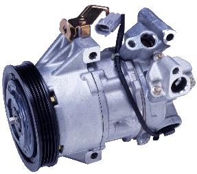
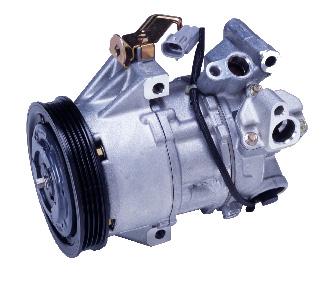
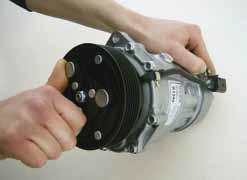
2 Compressor Installation All air-conditioning repairs should only be undertaken by someone that has sufficient knowledge and training that understands how the system works. Visually inspect the new unit for any damage ensuring that all fixing points are complete and that the pulley / front plate moves freely. Visually check the replacement unit against the item on the car to ensure they are the same. (BEFORE Removing the unit). (Once unit is removed) Check new compressor against old compressor ensuring units are the same and that the pulleys align correctly, in certain systems it is possible that different makes of compressors are interchangeable they may look slightly different however upon matching the fixing points, clutch and plug should all match. If completely flushing the system you will need to check the compressor and ensure the correct amount & type of oil. (Replacement compressors do not always come prefilled with oil). If you are not flushing the system (and the system is completely clean with no debris) you can drain the old compressor of oil, measure the amount and then ensure that the new compressor has teh same amount of oil 1-2fl oz unless it is GMA6 / YORK. (Replacement compressors do not always come with oil charge) Always check with the OEM reccommendation for the correct oil charge. DO NOT OVERCHARGE THE SYSTEM WITH OIL. When fitted to the vehicle rotate the front hub of the compressor by hand 10 times clockwise / anti-clockwise to ensure that the oil is distributed. Upon installation in certain circumstances it may be necessary to swap the manifold plate (where the pipes connect to the compressor) from the old unit to the new one. On remanufactured compressors and certain copy / pattern compressors it may be necessary to swap the wire plug from the old unit to the replacement unit.
3 Compressor Installation After installing the compressor, ensure that the last component installed is the receiver drier / accumulator, and then vacuum the system for a minimum of 30 minutes prior to leak testing. Once certain that there are no leaks, charge the air-con system with the correct amount of refrigerant and oil. Check the system operating pressures and temperatures, ensure that the Radiator / Condenser fans work correctly. You nust ensure that the high side pressures are not excessive and that the low side is not too low. When using Automatic / Semi Automatic charging stations, they do not add the oil charge to the Compressor, this must be completed prior to the Compressor installation. Please remember that Compressors do not just fail, there will be a reason why the original one failed. You must find and recify this underlying fault otherwise the replacement will also fail. When fitting clutch-less type compressors it is sometimes necessary to have the fault codes removed from the computer memory otherwise the compressor may not receive the correct feed and will not pump. You must always flush the systems to remove excess oil. Should the compressor not pump immediately then remove the control valve and sump drain plug, then blow through the control valve port ensuring that air is felt at the drain plug, this action ensures that the refrigerant bleed from the control valve to the swash plate is free and will then allow for the correct control valve operation. You must ensure that the compressor is fitted correctly and the above instructions have been followed when fitting the compressor, otherwise there will be no warranty. If you are replacing a compressor under warranty then you must complete and return the enclosed warranty form with the compressor for warranty consideration.


4 COMPRESSOR FAILURES The Suction port is dirty and black. Problem description : No varible Displacement or Compressor Seizure Cause of Failure : Insufficient cleaning of refrigerant cycle and/or not all required parts replaced. Resulting in : Dirt particles travel through the system and re-enter the compressor resulting in bad lubrication or clogged control valve. Rubber seals are swollen and do not fit in position. Problem Description : No variable displacement and/or system leakage. Cause of failure : 1) The system was charged with the wrong type of refrigerant. 2) Additives (conditioners) or wrong type flushing agents were used. Resulting in : The refrigerant, oil, additive or flushing agent resulted in swelling of the rubber seals. Discharge port is black and discoloured Problem Description : No varible displacement or compressor displacement Cause of failure : Low refrigerant amount or partially blocked refrigerant cycle. Resulting in : Insufficient oil return resulting in bad lubrication and overheating of the Compressor.


5 Compressor Failures Rubber particles at suction and discharge port Problem description : No varible displacement or compressor seizure Cause of Failure : Deterioration of rubber hose due to ageing of or a reaction with conditioners, sealers or flushing agents. Resulting in : Rubber material travels through the refrigerant cycle resulting in blockage and compressor failure. Clear separation of the two different oil liquids. Problem description : Excessive noise and/or compressor seizure Cause of Failure : POE Oil added to the refrigerant cycle. Pag oil and POE oil do not mix properly. Resulting in : A high percentage of POE will reduce lubrication performance. Clear separation of two different oil substances. Problem description : No variable displacement, system blockage or compressor seizure. Cause of Failure : PAO oil added to the refrigerant cycle. PAG oil and PAO oil do not mix and will cause a paraffin like substances. Resulting in : Clogging of control valve and/or refrigerant cycle.


6 COMPRESSOR FAILURES Suction port is clean and dry Problem Description : Compressor Seizure Cause of failure : Insufficient lubrication caused by Resulting in : 1, System blockage or 2, No run in proceedure 1, No oil return and no lubrication of compressor inner parts 2, Excessive engine rpm at first time operation provides insufficient time for oil and refrigerant to mix brfore returning to the compressor Broken hub limiter of the DL-pulley Problem Description : No Compressor operation Cause of failure : 1, Too high internal friction or complete seizure. 2, Liquid Lock. 3, Alternator free run pulley seized, broken belt tensioner, crank sharft damper or dual mass flywheel. Resulting in : For safety reasons the limiter of the pulley hub will break instead of drive belt Excessive drive belt movement results in negative force to the compressor pulley. Cracked or shattered plastic pulley Problem Description : Drive belt noise or drive belt disengaged. Cause of failure : 1, Incorrect removal or installation of the drive belt. 2, Hitting of the DL -pulley before or after installation. Resulting in : Excessive force was applied to the pulley resulting in cracks or shattering of the pulley.


7 Compressor Failures A hardened or a gel like substance inside the oil or suction port. Problem Description : No varable displacement, system blockage or compressor seizure. Cause of failure : Resulting in : Leak stop additive or conditioner added to the refrigerant cycle. Chenical reaction of the leak stop or conditioner caused blockage of the compressor control valve and or expansion valve. Pattern Compressors The one thing to remember with pattern compressors is that they are most often supplied with NO OIL, and will require oil adding to them before the compressor is fitted to the vehicle. Metal particles in the Piston shaft, where the piston has broken down because no oil was added. The wobble plate on this compressor was totally destroyed because no oil was added Orifice tube which has been totally blocked due to metal particles coming from the broken down compressor. The Orifice tube being blocked would stop the flow of refrigerant and oil to the new compressor when fitted and cause the same problem again


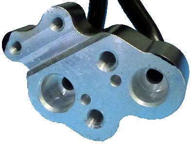
8 Remanufactured Compressors Some Remanufactured compressors will come with a manifold blanking plate. This is because the compressor may be suitable for more than one vehicle, it is just the manifold which is slightly different. If you have a compressor with a manifold blanking plate, simply remove the plate and swap the old manifold from the old compressor to the remanufactured compressor. The Manifold is where the pipes from the vehicle bolt onto the compressor.


9 How to check the oil in the Compressor 5. Let the oil flow into a measuring jug to state quantity 6. Adjust oil quantity according to manufacturer s advise 1.Loosen drain screw for oil care-2. Turn out drain screw completely 3. Remove drain screw 4.Exhaust compressor completely, turn clutch therefore 5. Let the oil flow into a measuring 6. Adjust oil quantity according to manufacturer s advise
10 WARRANTY FORM Invoice Number Part Number Make of Vehicle Model Year Engine Size Date of Installation Mileage at Installation Failure Date Mileage at Failure Please explain failure Did you change the filter drier / accumulator? Yes No Did you flush the system? Yes No What is the new system charge of oil? Oz/ML Type of oil Did you change the expansion valve? Yes No
11 If the compressor has broken down internally it is essential that the system is correctly flushed, otherwise the replacement unit will fail. Please explain how you flushed and with what machine WARRANTY FORM It is essential that the original invoice / work sheet is included when returning the compressor under warranty. Remember the compressor is only guaranteed against manufacturing defects and must be returned capped to prevent oil loss. (Do not empty the oil from the compressor), failure to do so will invalidate warranty. Comments : Company Engineer Date Engineers Signature
12 Cool Zone Automotive Technical Help :
COMPRESSORS REPLACEMENT PROCEDURE
 COMPRESSORS REPLACEMENT PROCEDURE INTRODUCTION Shown below, you can find the procedure that you must follow to replace compressors. INSTALLATION INSTRUCTION Steps to follow: 1) Remove the damaged compressor
Failure Mode Analysis
 Presented by: Brunno Covolan Pg. 1 : Introduction What is Failure Mode Analysis? Looking at the compressor to determine what was the cause of the failure. Why do we need to conduct Failure Mode Analysis?
To determine if an A/C clutch should be returned for Warranty Consideration:
 Warranty is a growing concern for all partners in the distribution of A/C Components. Because of the growing number of warranty questions, please study the following pictures to familiarize yourself with
Jeep Wrangler TJ 4.0 LITER Installation instructions
 www.jeepair.com 2000-2001 Jeep Wrangler TJ 4.0 LITER Installation instructions Important information about your system, and warranty DO NOT ADD ANY OIL TO ANY PART OF THE SYSTEM. DO NOT USE THE SIGHT GLASS
Understanding the Modern Automotive Air Conditioning System. Trainer: Grant Hand
 Understanding the Modern Automotive Air Conditioning System Trainer: Grant Hand AUTOMOTIVE TRAINING SOLUTIONS PTY LTD Training for the future... Automotive Training Solutions IMPORTANT NOTE Copyright The
Porsche 928 with 16v LH-Jetronic Fuel System
 Porsche 928 with 16v LH-Jetronic Fuel System Toll-Free Tech Hot Line: 877-FOR-928M 877-367-9286 Please do not copy this manual and give copies to your friends. Our ability to bring you this supercharger
MANUAL CONTROL / SEMIAUTO TEMPERATURE CONTROL HEATING, VENTILATION AND AIR CONDITIONING SYSTEM
 SECTION 7C MANUAL CONTROL / SEMIAUTO TEMPERATURE CONTROL HEATING, VENTILATION AND AIR CONDITIONING SYSTEM CAUTION: Disconnect the negative battery cable before removing or installing any electrical unit
Troubleshooting:Passenger Car
 Troubleshooting:Passenger Car Troubleshooting If the engine or other parts has the problem, it is possible to break the exchange turbocharger again. Please confirm the notes below and inspect each part
Table of Contents. 4. Before a New Turbocharger is Installed
 Table of Contents 1. Turbocharger Overview ------------------------------------------------------------------ 1.1. Definition -----------------------------------------------------------------------------
2003 Mustang Workshop Manual
 Page 1 of 6 SECTION 412-03: Air Conditioning 2003 Mustang Workshop Manual DESCRIPTION AND OPERATION Procedure revision date: 06/14/2002 Air Conditioning Printable View (225 KB) The A/C refrigerant system
Service and Repair. a. Remove the 2 nuts and 2 upper radiator support. b. Lift out the radiator and cooling fan assembly.
 Service and Repair REPLACEMENT 1. SEPARATE BATTERY NEGATIVE TERMINAL 2. REMOVE AIR CLEANER INLET NO.1 3. DRAIN ENGINE COOLANT 4. REMOVE V-BANK COVER 5. REMOVE INTAKE AIR CONNECTOR PIPE 6. REMOVE ENGINE
Jeep Wrangler 4.0 Liter TJ Jeep Wrangler 2.5 Liter TJ Installation instructions
 TM www.jeepair.com 1999 Jeep Wrangler 4.0 Liter TJ 1999-2001 Jeep Wrangler 2.5 Liter TJ Installation instructions Kit Information After 1994 every vehicle was designed for R134a refrigerant. The Jeep kit
A/C compressors: extending their service life
 FEATURE A/C compressors: extending their service life What can we say about the A/C compressor? Believe it or not, it is one of the hardestworking components on the vehicle. Its toughest job is to generate
Repair any problems or leaks before retrofitting. Affix labels to the vehicle showing conversion status. Observe all safety recommendations.
 The use of R134a in mobile A/C systems designed for R-1 2 refrigerant causes higher discharge pressures (as much as 10-15%) and necessitates changing the compressor lubricant from mineral oil (5GS) to
Jeep Wrangler TJ 4.0 LITER Installation instructions
 www.jeepair.com 2002-2004 Jeep Wrangler TJ 4.0 LITER Installation instructions Kit Information These directions are for 2002-2006 model Jeep Wranglers. After 1994 every vehicle was designed for R134a refrigerant.
RELEASING PRESSURE IN THE HYDRAULIC SYSTEM,
 Testing And Adjusting Introduction NOTE: For Specifications with illustrations, make reference to SPECIFICATIONS for 225 EXCAVATOR HYDRAULIC SYSTEM, Form No. SENR7734. If the Specifications are not the
GM LS Series Serpentine Drive System with & without Power Steering
 an ISO 9001:2015 Registered Company GM LS Series Serpentine Drive System with & without Power Steering 18865 Goll St. San Antonio, TX 78266 Phone: 800-862-6658 Sales: sales@vintageair.com Tech Support:
Routine Compressor Maintenance
 Establishing a regular, well-organized maintenance program and strictly following it is critical to maintaining the performance of a compressed air system. One person should be given the responsibility
IMPORTANT INFORMATION
 Table of Contents IMPORTANT INFORMATION Section 1B - Maintenance MAINTENANCE 1 B Specifications................................ 1B-1 Special Tools................................ 1B-2 Quicksilver Lubricant/Sealant..................
TSI Date Group No. Supp. Page
 Volvo Trucks North America, Inc. Greensboro, NC USA Timing Gear Cover TSI Date Group No. Supp. Page 11.2001 215 006 1(7) Timing Gear Cover D12C Fig. 1: VOLVO D12C Engine W2003244 This information covers
INSTALLATION INSTRUCTIONS
 INSTALLATION INSTRUCTIONS Accessory Application Publications No. AIR CONDITIONER CIVIC 2- AND 4-DOOR AII 24158 Issue Date SEP 2002 What s New The installation instructions for the 2003 Civic A/C are the
2003 Explorer Sport/Sport-Trac Workshop Manual. 7. Disconnect the vacuum harness connector. Remove the nut.
 7. Disconnect the vacuum harness connector. Remove the nut. 8. Remove two nuts, one bolt, and the A/C evaporator housing (19850). Remove the nut located at the bottom of the A/C evaporator housing first.
10. SEPARATE COMPRESSOR (a) Remove the nut, 3 bolts compressor stay and compressor. HINT: Hang up the hoses instead of detaching.
 Remove the nut, 3 bolts compressor stay and compressor. HINT: Hang up the hoses instead of detaching.") 14108 ENGINE MECHANICAL REPLACEMENT 1. DRAIN ENGINE COOLANT(See page165 ) 2. SEPARATE BATTERY NEGATIVE TERMINAL 3. REMOVE VBANK COVER SUBASSY (a) Remove the 2 cap nuts and Vbank cover subassy. 4. REMOVE
14108 ENGINE MECHANICAL REPLACEMENT 1. DRAIN ENGINE COOLANT(See page165 ) 2. SEPARATE BATTERY NEGATIVE TERMINAL 3. REMOVE VBANK COVER SUBASSY (a) Remove the 2 cap nuts and Vbank cover subassy. 4. REMOVE
928 Motorsports Supercharger Installation Copyright 2007, 928 Motorsports, LLC All Rights Reserved
 For Porsche 928 equipped with K-Jetronic (CIS) Fuel System Toll-Free Tech Hot Line: 877-FOR-928M 877-367-9286 Please do not copy this manual and give copies to your friends. Our ability to bring you this
Jeep Wrangler TJ. Complete Air Conditioning System. Slide Control Head. Installation instructions
 WWW.JEEPAIR.COM 1996-1998 Jeep Wrangler TJ Complete Air Conditioning System Slide Control Head Installation instructions Kit Information After 1994 every vehicle was designed for R134a refrigerant. The
Compressor Disassembly
 Compressor Disassembly Let's now move on to the compressor. My purpose in the rebuilt will be to replace every part that needs attention or is ready to fail plus retrofitting items intended for use of
CHILLER START UP PROCEDURE FORM DOC. N (DOC.N BELOW TO BE RETURN TO AERMEC)
") CHILLER START UP PROCEDURE FORM DOC. N 061103 (DOC.N 071103 BELOW TO BE RETURN TO AERMEC) 1. Preliminary Operation WARNING: The following operation must be done without the power supply (unit with the
CHILLER START UP PROCEDURE FORM DOC. N 061103 (DOC.N 071103 BELOW TO BE RETURN TO AERMEC) 1. Preliminary Operation WARNING: The following operation must be done without the power supply (unit with the
Section 10 Chapter 15
 Section 10 Chapter 15 24 Valve, 8.3 Liter Engine Note: All coding used in the 8.3 Liter and 9 Liter engine manuals are Cummins engine codes. These engine codes have no meaning to New Holland warranty codes
Badger Truck Refrigeration, Inc. Warranty Policy
 Badger Truck Refrigeration, Inc. Warranty Policy The manufacturer warrants each new heater, air conditioner or part to be free from defects in materials and workmanship under conditions of normal use and
GP-2000 : Trouble Shooting. Cause of problems
 VOL: MA-GP2000-2 Troubleshooting GP-2000 Technical Knowledge GP-2000 : Trouble Shooting Cause of problems 1: s related to other factors 2: s on the pressure reducing valve A : Reduced pressure exceed specified
 Page 1 of 50 Section 412-00: Climate Control System General Information DIAGSIS AND TESTING 1997 Mark VIII Workshop Manual Climate Control System Special Service Tool(s) 73 Digital Multimeter 105-R0051
Automotive Air Conditioning Manifold Gauge Sets
 Automotive Air Conditioning Manifold Gauge Sets 1 Caution: These instructions are not for use with Hybrid Vehicles. For instructions for servicing Hybrid Vehicles use Hybrid Vehicle manufacturer s service
TILLOTSON LTD., CLASH INDUSTRIAL ESTATE, TRALEE, CO. KERRY, IRELAND PHONE: FAX:
 TILLOTSON LTD., CLASH INDUSTRIAL ESTATE, TRALEE, CO. KERRY, IRELAND PHONE: +353 66 7121911 FAX: +353 66 7124503 e-mail: sales@tillotson.ie HR SERIES SERVICE MANUAL INTRODUCTION Tillotson has developed
IMPORTANT FITTING INSTRUCTIONS PLEASE READ THESE INSTRUCTIONS BEFORE FITTING YOUR TURBO. FAILING TO FOLLOW THEM COULD INVALIDATE THE WARRANTY.
 IMPORTANT FITTING INSTRUCTIONS! PLEASE READ THESE INSTRUCTIONS BEFORE FITTING YOUR TURBO. FAILING TO FOLLOW THEM COULD INVALIDATE THE WARRANTY. 1WHY DID THE LAST TURBO FAIL? Turbochargers are very reliable:
AIR CONDITIONING SYSTEM
 AC-1 AIR CONDITIONING SYSTEM GENERAL INFORMATION DESCRIPTION TROUBLESHOOTING PREPARATION REFRIGERATION SYSTEM DRIVE BELT REFRIGERATION LINES COMPRESSOR RECEIVER CONDENSOR COOLING UNIT COOL/ICE BOX EVAPORATORS
A/C SYSTEM GENERAL DIAGNOSTIC PROCEDURES
 Article Text ARTICLE BEGINNING 1993 AIR CONDITIONING & HEAT A/C General Diagnostic Procedures Diagnosis is an important first step in A/C system servicing. To save time and effort, systems should be carefully
 Page 1 of 6 Section 03-01C: Engine, 7.5L MFI 1996 Bronco/F-Series Workshop Manual IN-VEHICLE SERVICE Procedure revision date: 06/19/2000 Cylinder Heads Removal SPECIAL SERVICE TOOL(S) REQUIRED Description
13. FUEL SYSTEM/CARBURETOR/
 13 FUEL SYSTEM/CARBURETOR/FUEL PUMP FUEL SYSTEM --------------------------------------------------------- 13-1 SCHEMATIC DRAWING ---------------------------------------------- 13-2 OPERATION OF CARBURETOR
Engine Does Not Start or Is Hard to Start Cause of Trouble. 1. Open the drain screw, and check Fuel not supplied (1) Fuel tank empty
 Fuel tank empty") 20. Engine Does Not Start or Is Hard to Start 20-1 Engine Output Insufficient 20-2 Poor Performance at Low Speed and Idling 20-3 Poor Performance at High Speed 20-3 Unsatisfactory Operation 20-4 Fuel Gauge
20. Engine Does Not Start or Is Hard to Start 20-1 Engine Output Insufficient 20-2 Poor Performance at Low Speed and Idling 20-3 Poor Performance at High Speed 20-3 Unsatisfactory Operation 20-4 Fuel Gauge
A/C-HEATER SYSTEM - AUTOMATIC
 A/C-HEATER SYSTEM - AUTOMATIC 1988 Toyota Celica 1988 Automatic A/C-Heater Systems Celica * PLEASE READ THIS FIRST * CAUTION: When discharging air conditioning system, use only approved refrigerant recovery/recycling
84-86 Ford SVO Mustang AC Installation Guide
 84-86 Ford SVO Mustang AC Installation Guide This installation guide is for the AC installation kit from Late Model Restoration. The Vendor is Hose Wizards that manufactures this great kit that provides
Refrigerant Oil Calculation during Compressor Replacement
 Refrigerant Oil Calculation during Compressor Replacement Study Guide TMT: 100820 Dealer Education 2008 Navistar, Inc. 4201 Winfield Road, Warrenville, IL 60555. All rights reserved. No part of this publication
IMPORTANT INFORMATION
 Table of Contents IMPORTANT INFORMATION Section 1B - Maintenance MAINTENANCE 1 B Specifications........................... 1B-1 Special Tools........................... 1B-2 Mercury/Quicksilver Lubricants
Important information about your new a/c system. Please read the following directions prior to installing this a/c system.
 PAGE 1 Important information about your new a/c system. Please read the following directions prior to installing this a/c system. PN s: CK-7586258, CK-758642, CK-7586304, CK7586SBC, CK-7486NC Jeep CJ Series
26 - COOLING SYSTEM CONTENTS ENGINE COOLING - DESCRIPTION... 3 ENGINE COOLING - OPERATION... 9 COOLING SYSTEM FAULTS... 1
 26 - COOLING SYSTEM CONTENTS Page LAND ROVER V8 DESCRIPTION AND OPERATION ENGINE COOLING - DESCRIPTION... 3 ENGINE COOLING - OPERATION... 9 FAULT DIAGNOSIS COOLING SYSTEM FAULTS... 1 REPAIR COOLANT - DRAIN
Technical Bulletin. Drive Failure due to Incorrect Tensioner set-up. Transmission : Various Fuel : Petrol. Technical Details
 Bulletin No. : TB0025 Issue Date : Oct 2013 Pages : 7 Subject : Drive Failure due to Incorrect Tensioner set-up Part No. : QBK538 / QTB578 Description : Timing Belt Kit Make : Mitsubishi / Volvo Engine
Air Compressor. Operating & Maintenance Instructions 1110 ENGINE DRIVEN - 1 -
 Air Compressor ENGINE DRIVEN Operating & Maintenance Instructions 1110-1 - Read these safety instructions before using the equipment. INTRODUCTION Thank you for purchasing this Clarke portable compressor.
SAFETY AND OPERATING MANUAL
 SAFETY AND OPERATING MANUAL COLD WATER PETROL WATER BLASTERS Read Safety & Operating Instructions Before Commencing Operation THESE INSTRUCTIONS MUST BE READ AND ADHERED TO BEFORE OPERATING THIS MACHINE.
14-6. TSB Revision ENGINE COOLING ON-VEHICLE SERVICE
 14-6 RADIATOR CAP DRAIN PLUG ENGINE COOLING ON-VEHICLE SERVICE When removing the radiator cap, use care to avoid contact with hot coolant or steam Place a shop towel over the cap and turn the cap counterclockwise
DESCRIPTION AND OPERATION
 412-03-1 Air Conditioning 412-03-1 DESCRIPTION AND OPERATION Air Conditioning Refrigerant flow into the evaporator core is metered The air conditioning system components are: by an evaporator core orifice
Before you go through this booklet, we request you to go through the following general instruction before commissioning your hydraulic systems.
 Hello, We are proud to be on your suppliers list. During few years we came to know that most of our customers are satisfied by Yuken Hydraulic Products but some of our customers had minor problems and
2003 Land Rover Freelander S. CAUTION: DO NOT rotate crankshaft or camshafts with timing belt removed and cylinder heads installed.
 FRONT TIMING BELT CAUTION: DO NOT rotate crankshaft or camshafts with timing belt removed and cylinder heads installed. Removal CAUTION: Camshaft timing belt must be replaced if cylinder head is to be
TC Series Cooling Systems
 TC Series Cooling Systems Table of Contents Table of Contents...1 List of Figures...1 Safety...2 Introduction...2 General Specifications...2 Types of Coolant...2 Routine Maintenance...2 Surge Tank Coolant
WARNINGS. Maintenance must be properly done to avoid serious injury risks. Improper maintenance can result in injury or property damage.
 Foreword This service manual has been elaborated to help service personnel to provide efficient and correct service and maintenance on the TM31 (formerly called DKS 32) compressor (for HFC-134a) for automotive
Technical Service BULLETIN
 Technical Service BULLETIN Title: Models: 01 03 Sequoia TSB UPDATE NOTICE: The information contained in this TSB supercedes TSBs AC001 01 and AC001 02. The previous TSBs, AC001 01 and AC001 02, should
PACKING, HANDLING, TRANSPORTING AND STORING MOTORS
 PACKING, HANDLING, TRANSPORTING AND STORING MOTORS Make sure that the shaft of the motor is not loaded in any way and is protected from knocks. Axial loads or shocks may easily damage the bearings inside
TROUBLESHOOTING TABLE
 TROUBLESHOOTING TABLE TROUBLESHOOTING GUIDE GLOSARY OF TERMS VANE PUMPS NO FLOW, NO PRESSURE A) Is the pump rotating? a-1) Check if the coupling is rotating. If not, check the rotation of the electric
Troubleshooting The Transmission Hydraulic System
 416B, 426B, 428B, 436B, & 438B BACKHOE LOADERS TRANSMISSION Testing And Adjusting Troubleshooting The Transmission Hydraulic System Make reference to the following warning and pressure tap locations for
ENGINE COOLING Click on the applicable bookmark to selected the required model year
 ENGINE COOLING - ENGINE COOLING General Information/ Service Specifications/Lubricant/Sealants GENERAL INFORMATION 0000 The cooling system is designed to keep every part of the engine at appropriate temperature
1992 Clutch. Eclipse, Expo/Expo LRV, Galant, Mirage, Precis, 3000GT
 Article Text ARTICLE BEGINNING 1992 Clutch Eclipse, Expo/Expo LRV, Galant, Mirage, Precis, 3000GT DESCRIPTION All clutches are single disc type. Pressure plate assembly uses a diaphragm spring to engage
Purging Air From Divider Block Lubrication Systems
 FROST ENGINEERING SERVICE Purging Air From Lubrication Systems A D I V I S I O N O F G E C S E Y S A L E S & S E R V I C E DESCRIPTION Divider block lubrication systems operate correctly only when all
FUEL SYSTEM/CARBURETOR/FUEL PUMP
 13 FUEL SYSTEM/CARBURETOR/FUEL PUMP FUEL SYSTEM-------------------------------------------------------------------------------------13-1 SCHEMATIC DRAWING-------------------------------------------------------------------------13-2
Turbocharger Warranty Analysis Guidelines
 Turbocharger Warranty Analysis Guidelines Authorized Agent Use Only INTERSTATE-McBEE, LLC 5300 Lakeside Avenue Cleveland, Ohio 44114 U.S.A. 216-881-0015 Toll Free: 1-800-321-4234 Fax: 216-881-0805 www.interstate-mcbee.com
HVF110, 210, 310, 410HD
 342 N. Co. Rd. 400 East Valparaiso, IN 46383 219-464-8818 Fax 219-462-7985 www.heatwagon.com Installation and Maintenance Manual Please retain this manual for future reference. HVF110, 210, 310, 410HD
CHAPTER 3 ENGINE Models: J08C-TP and J08C-TR
 1 INDEX ENGINE 3-1-1 CHAPTER 3 ENGINE Models: J08C-TP and J08C-TR 3-228E-05 3 TROUBLESHOOTING... 3-1-3 SPECIAL TOOLS...3-2-1 ENGINE OVERHAUL CRITERIA... 3-3-1 DISMOUNTING THE ENGINE ASSEMBLY... 3-4-1 REMOVAL
Cooling System. Table of Contents
 Sub-Headings Safety 2 s 2 Cautions 2 Notes 2 Introduction 2 General Specifications 2 Engine 2 Coolant 2 Routine Maintenance 2 Hose Connections 4 Radiator, Charge Air and Heater Cores 4 Cooling System Leaks
LS Chevy With Variable Valve Timing (VVT)
") LS Chevy With Variable Valve Timing (VVT) S-Drive Pulley Kit INSTALLATION INSTRUCTIONS Before beginning the installation, please note: Please read all of the instructions thoroughly before beginning the
LS Chevy With Variable Valve Timing (VVT) S-Drive Pulley Kit INSTALLATION INSTRUCTIONS Before beginning the installation, please note: Please read all of the instructions thoroughly before beginning the
Hanna Daily Preventive Maintenance Schedule
 Hanna Daily Preventive Maintenance Schedule Location Location # Daily operation and inspection procedures to be performed by car wash personnel. Mark status in the spaces on the right after performing
TIMING AND ACCESSORY Ranges. Diagnostic Expert Analysis & Recommendations
 Diagnostic Expert Analysis & Recommendations MAJOR CAUSES OF TIMING BELT FAILURES: 1 Uneven breakage 2 A clean break 3 Detached or separation of the belt teeth 4 Ripped teeth 5 Split teeth 6 Loss of teeth
Manual A/C System Components in Engine Compartment, Servicing
 Page 1 of 5 Volkswagen > A4 > 1999-2006 Heating, Ventilation and Air Conditioning 87 - Manual A/C System Manual A/C System Components in Engine Compartment, Servicing CAUTION! Before beginning repairs:
Big Block Chevrolet INSTALLATION INSTRUCTIONS
 Big Block Chevrolet Engine Prep: INSTALLATION INSTRUCTIONS Disconnect battery Remove existing alternator, a/c compressor, and brackets. Remove all pulleys and brackets Clean front of block Chase the tapped
Trouble shooting general
 Trouble shooting general THINK before starting trouble shooting Every fault location process should follow a logical and systematical order. Usually it is wisest to start at the beginning: - Is the oil
1995 Mitsubishi Montero LS. Ensure timing marks are aligned. Mark timing belt direction of rotation.
 TIMING BELT NOTE: Ensure timing marks are aligned. Mark timing belt direction of rotation. Removal 1. Disconnect negative battery cable. Drain engine coolant. Remove engine coolant reservoir tank, fan
Starting up hydraulic systems
 General / Installation A hydraulic system that operates economically, safely, and trouble-free requires careful planning, as well as proper installation and start-up. Conscientious maintenance has a considerable
TSB #: 53 Date: 2/11/2011 HOLDEN (DELPHI) VARIABLE STROKE COMPRESSOR DIAGNOSIS STEP ACTION RESULT YES NO
 VARIABLE STROKE COMPRESSOR DIAGNOSIS STEP ACTION RESULT YES NO") HOLDEN (DELPHI) VARIABLE STROKE COMPRESSOR DIAGSIS TSB #: 53 Date: 2/11/2011 Initial Once Read: Even though the Holden variable stroke compressor manufactured by Delphi has been in the Australian market
HOLDEN (DELPHI) VARIABLE STROKE COMPRESSOR DIAGSIS TSB #: 53 Date: 2/11/2011 Initial Once Read: Even though the Holden variable stroke compressor manufactured by Delphi has been in the Australian market
GROUP CONTENTS GENERAL DESCRIPTION RADIATOR SPECIAL TOOL THERMOSTAT ENGINE COOLING DIAGNOSIS...
 14-1 GROUP 14 CONTENTS GENERAL DESCRIPTION 14-2 SPECIAL TOOL 14-2 ENGINE COOLING DIAGNOSIS 14-3 INTRODUCTION 14-3 TROUBLESHOOTING STRATEGY 14-3 SYMPTOM CHART 14-3 SYMPTOM PROCEDURES 14-4 ON-VEHICLE SERVICE
FBC CODES AND TRANSLATIONS TRANSLATION
 FBC CODES AND TRANSLATIONS CODE TRANSLATION 500 air cleaning system checked 501 air cleaner housing found cracked 502 repaired cracked air cleaner housing 503 renewed air cleaner housing 504 air intake
Section 35 Chapter 2 HYDRAULIC SYSTEM HOW IT WORKS AND TROUBLESHOOTING NH
 Section 35 Chapter HYDRAULIC SYSTEM HOW IT WORKS AND TROUBLESHOOTING 6-80NH TABLE OF CONTENTS GENERAL INTRODUCTION... 35-3 Hydraulic Pumps... 35-3 Standard Flow PFC Pump Layout... 35-5 MegaFlow PFC Pump
Clutches for Automobiles and Light Trucks
 Clutches for Automobiles and Light Trucks What does the Clutch do? Connects the engine torque to transmission when ENGAGED Unhooks engine from transmission when DISENGAGED Where is the driver s foot when
HEATER, AIR CONDITIONER AND VENTILATION
 55-1 HEATER, AIR CONDITIONER AND VENTILATION CONTENTS HEATER AND MANUAL AIR CONDITIONER...................... 3 GENERAL............................... 3 Outline of Change......................... 3 SERVICE
Section 10 Chapter 7
 Section 10 Chapter 7 24 Valve, 8.3 Liter Engine Troubleshooting Symptoms Identification Note: All coding used in the 8.3 Liter and 9 Liter engine manuals are Cummins engine codes. These engine codes have
D-Series Blowers and Exhausters
 Operation and Maintenance Manual D-Series MONOXIVENT - SOURCE CAPTURE SYSTEMS - info@ Oct. - 2015 MONOXVENT BLOWERS AND EXHAUSTERS D05-1 D05-3 D10-1 D10-3 D15-1 D15-3 D20-1 D20-3 D30-1 D30-3 ½ HP TEFC
2/17/2017 Timing Belt Service and Repair, Removal and Replacement
 http://repair.alldata.com/alldata/article/display.action?componentid=64&itypeid=401&nonstandardid=0&vehicleid=39554&miles=&printfriendly=com 1/22 http://repair.alldata.com/alldata/article/display.action?componentid=64&itypeid=401&nonstandardid=0&vehicleid=39554&miles=&printfriendly=com
Electrical Systems. Introduction
 Electrical Systems Figure 1. Major Components of the Car s Electrical System Introduction Electricity is used in nearly all systems of the automobile (Figure 1). It is much easier to understand what electricity
Fig. 1: Remove the bolts which fasten the upper timing belt cover... Fig. 2:... and remove the cover
 Show Timing Belt and Covers REMOVAL & INSTALLATION 1983 87 626 NOTE: For access, safely support the car, then remove the right front wheel and splash shield. 1. Loosen the alternator mounting bolts and
Table 6-1. Problems and solutions with pump operations. No Fluid Delivery
 Table 6-1. and solutions with pump operations No Fluid Delivery Fluid level in the reservoir is low. Oil intake pipe or inlet filter is plugged. Air leak in the inlet line prevents priming or causes noise
CHAPTER 21 ENVIRONMENT CONTROL. Section Title Page
 CHAPTER 21 ENVIRONMENT CONTROL Section Title Page 21-00 Description........................................ 21.1 21-10 Ventilation........................................ 21.3 21-11 Nose Vent................................
Engine, disassembling and
 Page 1 of 38 13-1 Engine, disassembling and assembling Lock carrier, moving into service position Special tools and equipment 3369 support tool 1 - Bolts 2 - Bolts 3 - Bolts 4 - Bolts 5 - Bore 45 Nm (33
9/28/2018. Refrigeration compressor operation, maintenance and safety
 Refrigeration compressor operation, maintenance and safety Presented By: Dhananjay S. Deshpande Company name: Technex HVAC&R Engg. Works 304, Shivshakti CHS, Sector 09, Plot no 15, Khanda colony, New Panvel
EXTERNAL CONTROL VALVE (ECV) EQUIPPED VARIABLE A/C COMPRESSOR DIAGNOSIS PROCEDURE
 EQUIPPED VARIABLE A/C COMPRESSOR DIAGNOSIS PROCEDURE") Technical Service Bulletin GROUP DATE HVAC JUNE, 2017 NUMBER MODEL(S) 17-HA-002 Multiple Models EXTERNAL CONTROL VALVE (ECV) EQUIPPED VARIABLE A/C COMPRESSOR DIAGNOSIS PROCEDURE This bulletin supersedes
Technical Service Bulletin GROUP DATE HVAC JUNE, 2017 NUMBER MODEL(S) 17-HA-002 Multiple Models EXTERNAL CONTROL VALVE (ECV) EQUIPPED VARIABLE A/C COMPRESSOR DIAGNOSIS PROCEDURE This bulletin supersedes
Air Trap TATSU2. Copyright 2013 by TLV CO., LTD. All rights reserved ISO 9001/ ISO M-02 (TATSU2) 7 August 2013.
 7 August 2013.") 172-65177M-02 (TATSU2) 7 August 2013 ISO 9001/ ISO 14001 Manufacturer Kakogawa, Japan is approved by LRQA LTD. to ISO 9001/14001 Air Trap TATSU2 Copyright 2013 by TLV CO., LTD. All rights reserved 1 Contents
172-65177M-02 (TATSU2) 7 August 2013 ISO 9001/ ISO 14001 Manufacturer Kakogawa, Japan is approved by LRQA LTD. to ISO 9001/14001 Air Trap TATSU2 Copyright 2013 by TLV CO., LTD. All rights reserved 1 Contents
User s Manual D-Series Blowers and Exhausters
 User s Manual D-Series Blowers and Exhausters D05-1 ½ HP TEFC 115/230 VOLTS, 1 PH D05-3 ½ HP TEFC 208/230/460 VOLTS, 3 PH D10-1 1 HP TEFC 115/230 VOLTS, 1 PH D10-3 1 HP TEFC 208/230/460 VOLTS, 3 PH D15-1
SPECIFICATIONS TEST AND ADJUSTMENT SPECIFICATIONS SPECIFICATIONS ENGINE FD620D, K SERIES
 ENGINE FD620D, K SERIES SPECIFICATIONS SPECIFICATIONS TEST AND ADJUSTMENT SPECIFICATIONS Engine Oil Pressure Sensor Activates............................... 98 kpa (14.2 psi) Oil Pressure While Cranking
Different oils are used in automotive A/C systems, based on the type of refrigerant. Polyalkylene Glycol (PAG) oil is used for R-134a refrigerant.
 oil is used for R-134a refrigerant.") Lubricants Automotive air conditioning lubricants are specially formulated because of how and where they operate. Air conditioning oils must be dry (having little or no water content) and mix with the
Lubricants Automotive air conditioning lubricants are specially formulated because of how and where they operate. Air conditioning oils must be dry (having little or no water content) and mix with the
WELDING FUME EXHAUSTERS & ARMS
 WELDING FUME EXHAUSTERS & ARMS The Ace 75 Series is our flexible and effective line of welding fume exhausters and extraction arms for shops that elect to exhaust their weld fumes outdoors instead of through
Oregon Fuel Injection
 Cummins PT Fuel Pump Diagnostic No Start, with no smoke 1. This could be caused by the fuel pump not turning or a seized gear pump. Remove the fuel supply hose and the fuel inlet fitting from the gear
Installation and Operating Manual
 Installation and Operating Manual L-Series Vacuum Pumps Models L/H400C - L/H630C INSTALLATION & OPERATING MANUAL L/H-SERIES SINGLE STAGE ROTARY VANE VACUUM PUMPS L/H400C-L/H630C Please read the manual
Eurovacuum Installations and Operating manual EV Series Vacuum pumps Models
 Eurovacuum Installations and Operating manual EV Series Vacuum pumps Models 0010-0630 Single Stage Oil Sealed Rotary Vane Pump Eurovacuum EV Series Single Stage Oil Sealed Rotary Vane Pumps Eurovacuum
February 26, ch.12.notebook. Ch. 12. Preventative Maintenance and Troubleshooting. Feb 23 5:03 PM
 Ch. 12 Preventative Maintenance and Troubleshooting Feb 23 5:03 PM 1 Why PM? preventive maintenance certain maintenance tasks must be performed regularly to keep an engine working properly helps premature
REMY TECHNICAL SERVICE BULLETIN
 June 2018 REMY TECHNICAL SERVICE BULLETIN Remy Power Products is continuously adding technical training and technical information. We welcome suggestions. If there is something technical you would like