Instructions for use. FORESTRY WINCHES 65H / 85H / 65Hpro / 85 Hpro. Instructions for safe work Spare parts list
|
|
|
- Winfred Watts
- 6 years ago
- Views:
Transcription

1 Manufacturer: d.o.o. Dobriša vas 14/a 3301 PETROVČE SLOVENIA TEL.: info@uniforest.si Instructions for use FORESTRY WINCHES 65H / 85H / 65Hpro / 85 Hpro Instructions for safe work Spare parts list
2 Index Technical data... 4 Instructions for safe work... 5 Instructions for use... 9 Settings Maintenance Removal of faults A list of replacement parts.. 22 A list of hydraulic replacement parts 28 Declaration
3 FORESTRY WINCHES 65H/ 85H / 65Hpro / 85Hpro Dear customer! We are pleased that you decided to purchase our machine. Forestry winch is a forestry machine of modern design, whose construction enables effective and safe work in the forest. Work in the forest can only be safe if you follow the instructions for safe work and use. Upon following all instructions, the machine will operate flawlessly, and you will avoid unnecessary costs. We recommend reading the instructions carefully. If you are not sure about something, you can also contact us. We wish you safe work. 1. Intended purpose The machine is intended exclusively for normal work in the forest. Any other use outside of this framework holds as unintended. The manufacturer is not liable for damages, resulting from unintended use. In this case, the user is the sole bearer of risk. Intended use also includes regarding operational, service and maintenance conditions, which are prescribed by the manufacturer. Only persons, who are trained and acquainted about the dangers and consequences, which can result from improper use, can operate the machine. Relevant safety regulations must also be followed, including generally valid safety-technical, occupational medicine and road traffic regulations. Own interference and modifications of the machine exclude the manufacturer s liability for damages resulting from this. 3
4 2. Technical data: Unit 65H 85H 65Hpro 85Hpro Connection category Pulling force kn Brake force kn 81,25 81,25 106,25 106,25 Wire rope medium speed m/s 0,60 0,60 0,60 0,60 Wire rope mm/m 11/135 11/135 12/128 12/128 maximum length mm/m 12/115 12/115 11/150 11/150 Wire rope length (serial) mm/m 12/80 12/80 13/90 13/90 Tractor kw >50 >50 required power PS >70 >70 Rated strength N/mm Width mm Depth mm Height without protective net mm Height with protective net mm Weight (without wire kg rope) Revolutions on cardan min-1 max 540 max 540 max 540 max 540 Unwinding device Option Serial 4

5 INSTRUCTIONS FOR SAFE WORK When operating the winch, you must devote maximum attention to safety! To prevent accidents, carefully read and follow the instructions below. General: 1. Beside guidelines in these instructions for use, follow also all generally valid safety and accident regulations. 2. The winch must be operated safely and regulations regarding safe work must be followed. 3. Only persons, who are older than 18 years, can operate or work with the winch. 4. Warning plates on the machine provide important instructions for safe operation. Follow them for your own safety. 5. The winch or its flawless operation must be checked before each use or at least once per working day. Defects must be eliminated professionally. The winch must be professionally inspected by an expert before first use and after major modifications or at least once a year. 6. When using public traffic routes, follow the signs and traffic regulations. 7. When working, it is obligatory to use personal protection equipment (helmet, gloves, appropriate footwear...). 8. Before taking off and inclusion, control the vicinity (children). Ensure adequate visibility. 9. Driving on winch during transport is prohibited. 10. The winch must be connected according to the instructions. 11. For road transport, prepare the machine as prescribed. If the winch covers the rear lights of the tractor and are not visible during transport, additional lights must be installed for driving on the road. 12. Drive speed must always be adjusted to environment conditions. When driving uphill or downhill and transversally to slope, avoid sudden turns. 13. Do not stand in the danger area. 5

. 19. With each intervention in the winch, the PTO shaft or the tractor must be shut down. 20.")


6 14. Nobody is allowed to stand between the tractor and the winch, if the tractor is not secured against movement with hand brake or with a wedge. 15. Until all winch elements are not still, it is prohibited to touch it. 16. Regularly check tightness of bolts. 17. The winch must be visually inspected before use. At least once a year, a professionally trained person must conduct an inspection. 18. The winch must not be used for other purposes (e.g. for lifting load figure 5). 19. With each intervention in the winch, the PTO shaft or the tractor must be shut down. 20. It is prohibited to remove protective elements on the winch. 21. Rope of appropriate strength and quality must be used for towing rope (see factor plate). 22. Damaged wire rope must be replaced immediately. 23. It is obligatory to use wire ropes of such length that, at full winding on the drum, the distance 1.5 of rope diameter to outside drum diameter remains. When unwinding the rope, a minimum of two windings must remain on the drum. 24. Assistant must not connect load to the winch, if the tractor operator is not aware of it. 25. It is especially dangerous to stand under the tree, which is to be towed (figure 1). 26. When using diverting pulley, there is a triangular area, which represents a danger Figure 1 Figure 2 6
. 30. The winch is not intended for lifting loads (figure 5). 31.")


7 27. When towing, respect the maximum allowed angle of 30 degrees (figure 3). 28. On dangerous terrain or with disregarding maximum allowed towing angle, danger of tipping over exists (figure 4). Figure 3 Figure 4 Figure Do not stand in the danger zone (figure 4). 30. The winch is not intended for lifting loads (figure 5). 31. Tractor operator and assistant must communicate constantly during work. 32. Winch operator must constantly observe the load during towing. If the terrain configuration does not allow it, the assistant must help him with this task. 33. The tractor, on which the winch is installed, must have a minimum tyre profile, which is still in accordance with road regulations. If not, chains must be installed on the wheels. Chains are also obligatory when working on snow and ice. 34. When disconnecting, you must first choose a solid and flat surface. The winch must be fixed with the help of support legs. PTO shaft is put on the prepared holder. 35. In the area of three-point hitch, there is a danger of injury, because of crushing and impact. 36. The winch can be operated only from a safe position, where the operator is not exposed to the danger of the load, rope, hook or the winch itself. A safe place is also the tractor seat, if the winch is fitted with an appropriate sized safety net. When operating the winch outside the tractor seat, the operator of the winch must have sufficient protection, e.g. with the tractor itself, with a safe position with adequate distance from the vehicle, e.g. behind a tree. Timber can be attended to from the side by the connection; shorter wood can be attended to diagonally behind the load (figure 6). 7


8 Oscillating rope Tow rope Torn-off-pulley Triangle area Danger area Pulley Tree Figure 6 Figure During towing, standing between the load is prohibited (figure 7). 38. For towing, use only low expansive rope of adequate strength, which are given on the winch type plate and in the manufacturer s instructions. PTO SHAFT 1. Only PTO shafts, which are prescribed by the manufacturer, can be used. 2. Cardan protection pipes and protection funnels and connection protection must be installed, which must be in perfect condition. 3. With PTO shafts, be careful with prescribed pipe protection in transport and working position. 4. Connect and disconnect the cardan only when the cardan power takeoff is disengaged, the engine is stopped and the ignition key is removed. 5. Always be careful to install and secure the cardan correctly. 6. Protect the cardan protection from rotation with hang chain. 7. Before engaging the PTO shaft on the tractor, make sure that the chosen number of revolutions and rotation direction comply with the requirements, given in the technical data chapter. 8. Before engaging the PTO shaft, be careful that nobody is standing in the machine s danger zone, which applies also to operation. 9. PTO shaft must never be engaged, when the engine is stopped. 10. Put the disconnected PTO shaft on the foreseen holder. 8
9 INSTRUCTIONS FOR USE DESCRIPTION The winch is a machine intended for storing chopped logs from the forest. Basic parts of the winch are: welded housing, drive part, drum with shaft, clutch, brake, upper and lower pulley and other smaller elements. Control is done by electro hydraulic system. Clutch and brake are engaged by hydraulic cylinders. Pressure in the hydraulic part is created by the hydraulic pump, which is driven by the PTO shaft. Hydraulic battery maintains required pressure in the system even after the pump becomes still or the tractor is shut down, which still enables to unwind the wire rope. Steering elements are powered by electricity from the electrical socket at the rear of the tractor. The winch operates with hydraulic pressure to maximum 160 bar. Safety valve is factory set and the pressure is not allowed to be increased! REQUIRED EQUIPMENT OF THE TRACTOR -PTO shaft with chosen gear ratio, max. 540 RPM. -Three-point hitch of I and II category. -electrical installation 12 V with socket on the rear of the tractor Maximum number of revolutions and direction of tractor PTO shaft rotation is 540 min -1. PTO SHAFT ADJUSTMENT Length of PTO shaft needs to be adjusted for different tractors (figure F1-F4). For winch 65H/85H/65Hpro/85Hpro, the use of PTO shaft with torque 695 Nm (type W 400E Walterscheid) is appropriate. Ascertain the accurate length in the following manner: 1. Shut down the tractor. 2. Connect the machine to the tractor. 3. Extract the PTO shaft apart and connect the individual shaft halves to the tractor and machine and compare them crosswise and mark them (figure F1). 4. Shorten external and internal plastic protection pipes (figure F2). 5. Shorten external and internal slide profiles with the same distance as plastic protection pipes (figure F3). 6. Crop the pipe end, remove fillings and grease the slide positions well (figure F4). 9

10 TRACTOR MOUNTING When connecting the winch, do not stand in the danger zone! Forestry winch can be connected to any tractor, which has a three-point hitch, with connection frame of category I or II. Appropriate construction also enables easy connection to the tractor with automatic connection rods. Connect the prescribed PTO shaft and secure cardan protection with a hang chain. Be careful that the cardan clicks into place on both connection points! For transfer of torque from the tractor to the winch, it is advisable to use a PTO shaft with a clutch. Once the winch is attached to the tractor, strengthen the stabilizers on the lower connection rods and level the winch with a hitch nut into position, so that the winch is tilted backwards for approximately 20 degrees. Electrical cable plug on the winch is connected to the socket on the tractor. Steering console is connected to the socket on the winch housing. When using remote control, receiver cable is connected to the socket, where the steering console used to be. 10
11 WIRE ROPE UNWINDING When the winch is properly connected, we can begin with unwinding of the wire rope. On tractors without a socket with constant current of 12 V, we can connect a supply cable in the socket, which is usually made for connection of light equipment on the trailer. Because of this, we have to turn on the position lights. On the steering console (figure 8), press the left button to release the brake. Hydraulic cylinder shifts to position 1. If we disengage pressure on the button in less than 3 seconds, the brake cylinder shuts and the winch is again open and unwinding is not possible. If this button is pressed for more than 3 seconds, the function shifts from impulse to constant release and despite not holding the button, the cylinder stays in the open position and the winch in unwinding function. When unwinding, we have to be careful not to unwind the wire rope completely or leave at least three winds on the drum. This distance is marked on the wire rope. Due to safety reasons, the wire rope is installed on the drum so that if the logs start to slide without control, the rope must pull itself off the drum. If the rope was pulled out with excessive force, we can pull out the entire wire rope during pulling. In this case, replace it according to the procedure, foreseen for wire rope installation. If the wire rope is very tight and we wish to release it, we have to do it impulsively with quick presses 2-3 times on the left button. This prevents the wire rope to unwind too quickly from the drum and that the wire rope is not too loose. It also prevents the logs to slide downhill. Warning Steel rope must be completely unwound before first use and wind it back on the generator drum under load. For instance, we can do this so that we attach the rope to a standing tree and pull the tractor with slight braking to the tree. This procedure must be done also before trying to tow, if we towed downhill beforehand or if the rope was wound loosely during towing. ATTENTION! Loosely wound steel rope can be damaged (stuck, bent) at greater load, so that it is prohibited to use it again. Warranty does not apply for a steel rope, which is damaged in such manner. 11
.")
12 Figure WINCH CONTROLER We can start pulling, when the winch is on the ground and properly strengthened. Apply the hand brake on the tractor. If the PTO shaft is engaged and the hydraulic system requires pressure, we can start pulling. Press the right button on the steering console (pos. 2, figure 8). The wire rope starts winding on the drum. When we release the button, the winding stops. If the unwinding of the wire rope does not stop immediately after releasing the button, the winch is malfunctioning. Immediately stop work and contact service company, because operating the winch in this case is deadly! During pulling it is forbidden to lift the winch, because this can damage the connection PTO shaft on the winch. In case of ultra vires or danger of accident, immediately press the red button (pos. 3) to put the winch in a standstill. 12
13 SETTINGS Figure 9 CLUTCH Before any modification on the winch, shut off the tractor engine! Pulling force on the clutch is factory set and does not require to be changed. Due to wear of friction surfaces, distance between clutches needs to be set after a certain period. This is done once a year at usual work in the forest or after every 1000 m3 of pulled out logs, but not before end of warranty period. Perform the setting by unscrewing the nut (pos. 9, figure 11), which is the safety nut, to the left. Then, tighten the high nut (pos. 15, figure 11) to the right. In this position, there is no distance between the clutches. Then, unwind the nut for one turn to the left this creates a gap between the lamellas of approximately 4-5 mm. Retighten the safety nut (pos. 9, figure 11) to the right. This protects the high nut from unwinding. Engage the motor and PTO shaft, pull out the rope and begin controlling the adjustment. If, despite not engaging the right button for pulling, the rope starts to move, then the distance between the clutches is too small. Increase it for approximately 1 millimeter or repeat the setting procedure by unwinding the high nut for ¼ of a turn to the left. Engaging pulling is not allowed, if the nuts (pos. 9 and 15, figure 11) are not installed on the shaft, because the hydraulic cylinder of the clutch gets damages, because the maximum permitted travel is only 8 mm! WARNING If the cylinder stroke is greater than 8 mm, oil can leak on clutches. PRELIMINARY BRAKE Set the pre-brake with screw (pos. 4, fig. 11) and nut (pos. 5, fig. 11). By rotating the bolt to the right, the brake force is increased, with rotating to the left, the brake force is decreased. Then tighten the wing nut, which prevents the bolt to loosen automatically. Proper setting ensures that the wire rope does not roll off the drum automatically or excessively. This would cause loose winding and damage to the wire rope at fast disburdening of the brake and unwinding. Preliminary brake is properly set when unwinding of the rope is still possible without excessive effort. If you pull the rope uphill, it is possible to additionally disburden the brake, so that rope towing is easier, the bolt (pos. 4, figure 11) must be returned to its original position immediately after. 13
14 BRAKE At the end of pulling, the differential brake automatically engages. Brake is factory set to brake force, which is 25% greater than the nominal towing force of the winch. By wear of the brake pad, the brake force changes, therefore it has to be set again. This is needed, when the brake does not hold the load as described in the beginning of this paragraph. Set the brake force by loosening or tightening the screw (pos. 2, fig. 11) and loosen the safety nut (pos. 3, fig. 11) beforehand. When tightening the screw (pos. 2, fig. 11), the brake force decreases, and when loosening the screw, the brake force increases. After finishing setting tighten the safety nut (pos. 3, fig. 11). Correctly set band brake in the on position disables the load to slide backwards, and in the off position, it enables smooth pulling of the rope from the winch. Figure 10 Figure 11 14
15 DRIVE CHAIN TENSIONING After a certain period of operation (10 hours), the drive chain stretches; therefore it must be checked frequently and tensioned, if required. It must be checked every 500 hours of operation. Tensioning is done according to the following procedure (figure 12)! First, disengage the PTO shaft and turn off the engine. Remove the protective sheet of the PTO shaft (pos. 1,fig.12)). Loosen the nuts (pos. 2, pos. 8, fig. 12), which fix the lower drive (pos. 3, pos. 9, fig. 12). Then loosen the safety nut (pos. 12, fig. 12) and use screw (pos. 13, fig. 12) to tension the longer chain (pos. 6). Turn this screw to the right until you set the correct tension of the chain. Chain is correctly tensioned when it still swings approx. 3 to 4 mm in the transverse direction. Them, with the counter-nut (pos. 12, fig. 12), tighten the screw, which prevents the tensioning device to loosen. Now securely tighten all four nuts on the lower drive (pos. 2, fig. 12). Then start to tension the shorter chain (pos. 8, fig. 12). If you have already loosened the four nuts (pos. 8, fig. 12), loosen the nut (pos. 11, fig. 12) and start turning the tensioning screw (pos. 10, fig. 12) to the left. This increases the distance between both housings. When the chain (pos. 7, fig. 12) is properly tensioned, tighten the nut (pos. 11, fig. 12) and other nuts (pos. 8). 15

16 Figure 12 16
17 WIRE ROPE ASSEMBLY First, remove the triangular protective net on the winch column. Then rotate the cover (pos. 7, figure 11) and rotate the drum in a position, which enables unscrewing of the bolt (pos. 8, figure 11)on the drum. Insert the wire rope in the guide of the upper pulley and direct it through the upper pulley to the rope drum. Insert the rope in the groove and tighten the bolt (pos. 8). Then start to wind according to the procedure, which applies to towing. Once the entire length of the wire rope is wound, unwind it again and wind it again strongly according to the procedure, which is described in the chapter Wire rope unwinding to prevent damage to the rope. MAINTENANCE LUBRICATION Before proceeding with maintenance work, shut down the engine, remove the key and wait for all moving parts to stop. There is a grease fitting on the winch, which enables greasing of the upper pulley and guide. The second grease fitting is on the housing of the lower pulley. Greasing is required every 60 hours of operation. The PTO shaft needs to be lubricated according to instructions of the manufacturer. Non-frequent greasing can cause wear of slide elements and consequentially a defect, which is not subject to warranty terms! Drive chain must be lubricated every 200 hours of operation. Lubricate it with spray for lubrication of chains or special grease, which does not melt at high temperatures, because the grease can come into contact with friction coating of the clutch. First, remove the cardan shaft protection, which must be fitted back after finishing lubrication. Clean the chain before lubrication. Do not lubricate the part, where the grease can reach clutch with application. If grease comes into contact with friction coating of the clutch due do improper and excessive lubrication, this would mean a drastic reduction in pulling force and consequentially it would be required to replace the blades of the clutch, which cannot be a subject of this warranty! All other bearings on the winch are of closed type, therefore greasing is not necessary. 17
18 CONTROL OF HYDRAULIC OIL Oil level in the tank needs to be controlled occasionally. Oil level in the tank is 3 liters. Hydraulic system uses oil for hydraulic systems ISO 32. First oil change must be done after 100 hours of operation. Each next change must be done after 1000 hours of operation or at least once a year. Oil temperature must be checked during operation. If it exceeds 70 C, the cardan must be stopped and determine the cause of overheating. If you do not have a thermometer present, you can determine the oil temperature by touching the hydraulic line. This must be done only with the engine switched off or else the hydraulic system can malfunction. Oil level is controlled with stick on the tank cover (fig. 13). Here you also fill in oil. With any work on the hydraulic system, pressure in the system must be released. Do this by pressing the left button on the control console (pos. 1, fig. 8) several times, until the pressure drops to 0 bar (pos. 1, fig. 14). Remove the triangular protection on the winch pillar and cardan protection beforehand. Release the oil from the tank (fig. 13) on the tube, which goes from the pump to the tank. There is a filter on the bottom of the tank, which must be replace with every oil change. High-pressure filter (pos. 2, fig. 14) must also be cleaned. Replenishing of oil Release of oil Figure 13 Figure 14 18
19 REMOVAL OF FAULTS Determined fault (malfunctions) Manometer does not show pressure. Pressure drops too quickly. Clutch cannot be engaged. Brake cannot be engaged. Cause Manometer does not work. Sprocket does not drive the pump (broken axle, broken chains, spring pin on the sprocket). Impurities in pressure valve. Folded tube. Not enough oil in the tank. Pump malfunction. The battery s membrane is damaged or nitrogen level in the battery is incorrect. Impurities in steering valve. Non-return valve does not seal (impurities or malfunction). Pressure valve does not seal (impurities or malfunction). Impurities in steering valve. No voltage / electrical current on the electro-magnetic coil. Insufficient voltage on the electromagnetic valve (min 11.6 V). Electro-magnetic coil does not work. Impurities in steering valve. No voltage / electrical current on the electro-magnetic coil. Insufficient voltage on the electro-magnetic valve (min 11.6 V). Electro-magnetic coil does not work. Procedure for removal of faults (malfunctions) Replace the manometer. Replace the damaged part. Unscrew the valve, clean it and replace it. Replace the tube. Fill up oil in the tank. Replace the pump. Fill up nitrogen or replace the battery. Unscrew the valve, clean it and replace it. Unscrew the valve, clean it and replace it. Unscrew the valve, clean it and replace it or change it. Unscrew the valve, clean it and replace it. Check the electrical wiring and contacts. Check the electrical installation on the tractor. Change the electromagnetic coil. Unscrew the valve, clean it and replace it. Check the electrical wiring and contacts. Check the electrical installation on the tractor. Change the electromagnetic coil. 19
20 Determined fault (malfunctions) Pressure oscillates. Insufficient pulling force. Insufficient brake force. Wire rope cannot be pulled out or the pulling is difficult. Cause With each engagement of electromagnetic valve it is normal for the pressure to oscillate. If the pressure oscillates, when the valves are not engaging, this means that the pressure valve is damaged or there are impurities in the valve. Grease on frictional padding of the clutch. Burnt frictional padding of the clutch. Insufficient pressure in hydraulic system (required pressure at least 140 bar). Worn frictional padding of the clutch. Incorrectly installed clutch. Improper setting. Grease on the padding of the brake belt. Damaged brake belt. Damaged brake mechanism. Improper setting of pre-brake. Improper setting of brake. Damaged or stuck wire rope. Damaged brake belt. Procedure for removal of faults (malfunctions) Change or clean the pressure valve. Replace clutches. Clean padding with sandpaper or grind (thickness approximately 0.5 mm). Determine the reason for pressure drop. Replace clutches. Install according to technical documentation. Setting according to instructions for use. Replace the brake belt. Replace the brake belt. Replace damaged parts. Setting according to instructions. Setting according to instructions. Pull out the rope with a tractor and, if required, install a new wire rope. Replace the brake belt. 20
21 Determined fault (malfunctions) The winch pulls, despite the clutch being disengaged. Cause Error on electro-magnetic valve. Not enough clutch distance. Broken part of frictional padding on the clutch. Excessively tensioned drive chain. Damaged winch drum. Procedure for removal of faults (malfunctions) Cease work immediately and consult a service company. Setting according to instructions. Replace clutches. Chain setting according to instructions Replacement or repair of the drum. 21
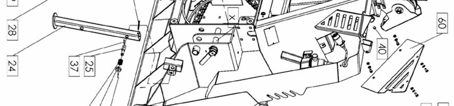
22 A LIST OF REPLACEMENT PARTS Forestry winches 65H, 65Hpro, 85H, 85Hpro (Figure 1) Position Name Design or standard number 65H, 65Hpro 85H, 85Hpro No. of pieces No. of pieces 1 Framework Small cover Cover Shaft holder Spacer Braking belt Bearing Z 5 DIN DIN Rope drum Freewheel spring Clutch Clutch Large freewheel z = Drum shaft Connection Connection guard Connection pin Adjusting screw Protective nut Pressure spring Pin Ø Hydraulics protection Safety net Safety net - small Foot A A 22
23 Position Name Design or standard number 65H, 65Hpro 85H, 85Hpro No. of pieces No. of pieces 25 Foot cork Holder Pressure spring Adapter Long nut M Breaking belt plate U holder Breaking belt roller Tensioning screw Breaking belt pin 1 / 1 / 35 Breaking belt plate Spring pin 3 x 20 1 DIN DIN Spring pin 6 x 30 6 DIN DIN Cotter 5 x 50 2 DIN 94 2 DIN Spring fuse 10 + chain 2 DIN DIN Greaser M8 1 DIN DIN Screw M12 x 40 1 DIN DIN Nut M12 3 DIN DIN Screw M8 x DIN DIN Washer M8 21 DIN DIN Washer M14 4 BN BN Screw M14 x 30 3 DIN DIN Screw M14 x 25 1 DIN DIN Nut M50 1 DIN DIN Nut M50 1 DIN DIN Screw M10 x 70 2 DIN DIN Screw M12 x 50 2 DIN DIN Pressure spring Nut M12 3 DIN DIN Washer M8 9 DIN DIN Screw M12 x 65 1 DIN DIN Screw M12 x 45 2 DIN DIN Washer M10 1 DIN DIN Nut M8 9 DIN DIN Spring pin 4 x 16 1 DIN DIN Guard L Guard R


24 24 65H, 65Hpro, 85H, 85Hpro
25 A LIST OF REPLACEMENT PARTS Forestry winches 65H, 65Hpro, 85H, 85Hpro (Figure 2) Position Name Design or standard number 65H, 65Hpro 85H, 85Hpro No. of pieces No. of pieces 1 Lower pulley housing A Protective pin of the lower pulley 3 Lower pulley pin A Lower pulley axis A 5 Bearing RS 2 DIN DIN Pulley wheel Lower pulley Upper pin Snap ring 1 DIN DIN Guide sleeve Lower pin Rivet 5mm 4 DIN DIN Shaft guard Drive cover Chain 1" 16B1 1 DIN DIN Master link 1" 16B1 1 DIN DIN Chain with a freewheel z = Dowel A 12 x 8 x 28 2 DIN DIN Bearing ZR 4 DIN DIN Lower drive housing Freewheel Protective washer MB 8 2 DIN DIN Nut KM/8 M40 x 1,5 2 DIN DIN Entire lower drive Longer chain 1 DIN DIN Master link 1 DIN DIN Drive shaft Vent 1 Mintor 1 Mintor 29 Sealing cover 1 DIN DIN Upper drive housing Entire upper drive A A 32 Pinion Pinion Pinion axis Pinion Upper pulley housing Upper pulley reinforcement / / A 25
26 Position Name Design or standard number 65H, 65Hpro 85H, 85Hpro No. of pieces No. of pieces 38 Upper pulley axis Upper pulley spacer Upper pulley wire rope 1 1 guide Upper pulley Spring pin 8 x 50 2 DIN DIN Spring pin 6 x 45 1 DIN DIN Pin holder Spring fuse 10 + chain 1 DIN DIN Spring fuse 8 + chain 2 DIN DIN Guard Spring pin 6 x 15 2 DIN DIN Screw M12 1 DIN DIN Spring Washer M8 11 DIN DIN Nut M12 7 DIN DIN Washer M12 16 DIN DIN Screw M12 x DIN DIN Nut M16 2 DIN DIN Screw M16 x 55 1 DIN DIN Screw M16 x DIN DIN Screw M5 x 10 1 ISO ISO Screw M12 x 80 2 ISO ISO Screw M12 x 50 2 DIN DIN Washer M12 2 DIN DIN Magnet 1 / 1 / 65 Greaser M8 1 DIN DIN Bearing DIN DIN Washer Washer 1 DIN DIN Sealing cover 1 DIN DIN Screw M8 x 16 3 DIN DIN Screw M14 x 50 / / 2 DIN Washer M14 / / 2 DIN Washer 35 4 DIN DIN


27 27 65H, 65Hpro, 85H, 85Hpro
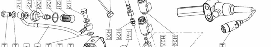
28 A LIST OF HYDRAULIC REPLACEMENT PARTS Forestry winches 65H, 65Hpro, 85H, 85Hpro (Figure H) Position Name No. of pieces H1 Hydraulic hose 1 H2 Hydraulic hose 1 H3 Hydraulic hose 1 H4 Hydraulic hose 1 H5 Hydraulic hose 1 H6 High pressure filter 1 H7 Safety valve 1 H8 Angular connector 1 H9 Hydraulic plug 1/4 1 H10 Hydraulic manometer connection 1 H11 Hydraulic bolt through 1/4 3 H12 Hydraulic bolt through 3/8 3 H13 Cu washer 1/4 6 H14 Cu washer 3/8 6 H15 Hydraulic pump 1 H16 Hydraulic brake cylinder 1 H17 Hydraulic clutch cylinder 1 H18 Hydraulic block 1 H19 Reservoir 1 H20 Reservoir cover TCL S3G 1/2 1 H21 Suction filter 1/4 90µm 1 H22 Hydraulic membrane accumulator 75 1 H23 Manometer 1 H24 Gasket set 1 H25 Coil 2 H26 Electromagnetic valve 2 H27 Safety valve 1 H28 7-pin socket aluminium 1 H29 Hydraulic connection ¼`` / 16 2 H30 Hydraulic connection ¼`` ¼`` 1 H31 Hydraulic extension ¼`` ¼`` 1 Number Notes 28
29 Position Name No. of pieces H32 Hydraulic connection ½ `` ½ `` 1 H33 Reservoir cover gasket 1 H34 Cu washer 21x26x1.5 2 H35 Cu washer 36x42x2 1 H36 Plug 2 H37 Connector 2 H38 Steering console 1 H39 Cylinder spring 1 H40 Cu washer 14x18/20 1 H41 Hydraulic connection ¼``/ 14 1 H42 Hydraulic connection 3/8`` ¼`` 1 H43 Hydraulic connection 3/8``/ 16 1 H44 Hydraulic connection M36x1,5 3/8" 1 Number Notes 29
30 30


31 31
32 EC Declaration of conformity In accordance with EC guideline 2006/42/EC and Regulation on machine safety (Ur.list RS, št.75/08) we d.o.o. Dobriša vas 14, 3301 PETROVČE, SLOVENIA Marko Polak, BE, Uniforest, Dobriša vas 14, 3301 PETROVČE declare with full responsibility that the following product: Winch: UNIFOREST 45H, 55H, 55Hpro, 65H, 65Hpro, 85H, 85Hpro meets the basic safety and health requirements of EC guideline 2006/42/EC and Regulation on machine safety (Ur.list RS, št.75/08) For appropriate enforcement of relevant safety and health requirements of EC guidelines, the following standards and/or technical regulations were applied: EN ISO 12100/2010 EN ISO /2010/ AC:2011 EN ISO 13857/2008 EN ISO 4413/2010 ÖNORM L5276/ 2008 Petrovče, Drago Pintar, BE 32
Instructions for use FORESTRY WINCH 65M/85M. Instructions for safe work Spare parts list
 Manufacturer: d. o. o. SI-3301 PETROVČE Tel.: 00386/3777 14 10 E-mail: info@uniforest.si Instructions for use FORESTRY WINCH 65M/85M Instructions for safe work Spare parts list 1 GENERAL Dear customer!
Original Operating Manual
 matev GmbH Nürnberger Str. 50 90579 Langenzenn T +49 (0) 9101 9087-0 F +49 (0) 9101 9087-20 info@matev.eu www.matev.eu Original Operating Manual Snow blade SRM-FB 120 CD Angle adjustment mechanical Version
Original Operating Manual
 matev GmbH Nürnberger Str. 50 90579 Langenzenn T +49 (0) 9101 9087-0 F +49 (0) 9101 9087-20 info@matev.eu www.matev.eu Original Operating Manual Front Power System und Front PTO shaft FPS- JD X 950 R for
6.0 Vehicles and machinery
 Code of Practice for Preventing Injury and Occupational Ill Health in Agriculture 6.0 Vehicles and machinery 6.1. Risk assessment Farm vehicles and machinery account for the highest proportion of farm
Northern Sales & Distribution Centre
 User Manual Industrial Door Northern Sales & Distribution Centre The Door Centre, Discovery Park, Crossley Road, Stockport, SK4 5BW /indupart /indupart /indupart /company/indupart-ltd Foreword This user
4332LR LR CR
 4332LR - 4336LR - 4336CR Operator's Manual Translated from the original instruction manual Version 2012-03 Date printed 03.2012 Language EN Machine no. KT422977 Document no. 90015106EN Index number 2012-03
Repair Manual 11/99 PS-34. Page 1
 Repair Manual /99 PS-4 Page Table of contents Index Technical Data page Special tools 4 Repair instructions, general 0 Chain brake 6 0 Centrifugal clutch 8 0 Oil pump 9-04 Ignition system - 0 Starting
Operating and Maintenance Manual. for. HADEF overhead crane. as jointed crane TA
 5.52.714.00.1.0 Edition 03.2004 GB Operating and Maintenance Manual for HADEF overhead crane as jointed crane TA Subject to changes. 1 HADEF Table of Contents 1 General Page 3 2 Product description Page
INSTRUCTION MANUAL MAGNA RAIL
 R ENGLISH NR. 148293 00 INSTRUCTION MANUAL MAGNA RAIL 1999-05-01 List of contents Declaration of conformity, CE Delivery check Mounting instruction (rail, trolley units) Mounting instruction (exhaust pipe,
ROTARY TILLER. Operation, Service & Parts Manual For P-P/C Series. November 1996 (Rev. 4-05) FORM: PTillerBook.QXD
 FORM: PTillerBook.QXD") ROTARY TILLER Operation, Service & Parts Manual For P-P/C Series FORM: PTillerBook.QXD November 1996 (Rev. 4-05) TABLE OF CONTENTS Preparation......................................1 Assembly Instructions.............................2
ROTARY TILLER Operation, Service & Parts Manual For P-P/C Series FORM: PTillerBook.QXD November 1996 (Rev. 4-05) TABLE OF CONTENTS Preparation......................................1 Assembly Instructions.............................2
SERVICE MANUAL US. Permobil M300/M400. Power Wheelchair
 SERVICE MANUAL US Permobil M300/M400 Power Wheelchair How to contact Permobil Head Office of the Permobil group Produced and published by Permobil AB, Sweden Version 2, 2011-06 Article no.: 205261-US-0
Instructions for Use Plain Trolley ULK Geared Trolley UHK
 Instructions for Use Plain Trolley Geared Trolley Item no. Load-carrying capacity (payload) Weight Trolley widths *special trolley widths* Device dimensions mm H / W / D Minimum curve radius mm -005 0,5
SERVICE MANUAL. Permobil C350. Power Wheelchair
 SERVICE MANUAL US Permobil C350 Power Wheelchair Contents Contents Introduction... 5 Rating plates... 6 Covers... 8 Batteries... 10 Rear wheels... 12 Support wheels... 14 Front wheels... 16 Wheel fork...
Original operating manual
 matev GmbH Nürnberger Str. 50 90579 Langenzenn T +49 9101 9087-0 F +49 9101 9087-20 info@matev.eu www.matev.eu Original operating manual Engine PTO Shaft FPS-PTO JD-3R for John Deere, type 3033R, 3038R,
Fransgård. Manual GB V-4000 V Farm tractor winch
 Fransgård Manual GB Farm tractor winch V-4000 V-6500 Fransgård Maskinfabrik A/S Fredbjergvej 132 DK - 9640 Farsø Telefon : +45 98 63 21 22 Fax : +45 98 63 18 65 Web : www.fransgard.dk E-mail : info@fransgard.dk
Edition Manual Chapter Page Workshop Manual, Stiga Park 5 Belts 11
 2008-05-19 Workshop Manual, Stiga Park 5 Belts 11 Pro 20 1. Dismantle the belts A and B as described above. 2. Block up the rear frame and remove the right rear wheel. Clean carefully the insex hole in
Assembly and Maintenance Manual Type ASNU
 Assembly and Maintenance Manual Type ASNU Hatschekstr.36 69126 Heidelberg Germany Tel +49(0)6221 30470 Fax +49(0)6221 304731 info@stieber.de www.stieber.de Date of issue: 30.05.2018 GB Revision: 0 U:\EngUsers\!ProduktDoku\1AAA_Einbauerklaerung_Wartungsanleitung_Konformitaetserklaerung\1AAA_Wartungsanleitungen\Orginal_Worddatei\_ASNU.docx
LOG CHOP. Hydraulic Wood Guillotine. Owners Illustrated Instruction Book & Parts List
 LOG CHOP Hydraulic Wood Guillotine Owners Illustrated Instruction Book & Parts List Grovebury Road, Leighton Buzzard, Bedfordshire. LU7 4UX. UK. Tel:01525 375157. Fax:01525 385222. Email: enquires@brownsagricultural.co.uk
DM-135 DRUM MOWER USER S MANUAL
 DM-135 DRUM MOWER USER S MANUAL 1 DM135 DRUM MOWER INSTRUCTIONS CHAPTER 1 SAFE OPERATION Do not attempt to operate the mower until you have read the operator s manual and all the safety signs on the mower.
Assembly and Maintenance Manual Type AS
 Assembly and Maintenance Manual Type AS Hatschekstr.36 69126 Heidelberg Germany Tel +49(0)6221 30470 Fax +49(0)6221 304731 info@stieber.de www.stieber.de Date of issue: 30.05.2018 GB Revision: 0 U:\EngUsers\!ProduktDoku\1AAA_Einbauerklaerung_Wartungsanleitung_Konformitaetserklaerung\1AAA_Wartungsanleitungen\Orginal_Worddatei\_AS.docx
Operating Instructions Declaration of Conformity Spare Parts List. Sub-Tiller 2.5 m / 3.0 m / 3.5 m / 4.0 m (rigid)
") UK Operating Instructions Declaration of Conformity Spare Parts List Sub-Tiller 2.5 m / 3.0 m / 3.5 m / 4.0 m (rigid) Important: Before using the machine, please study the Operating Instructions thoroughly
UK Operating Instructions Declaration of Conformity Spare Parts List Sub-Tiller 2.5 m / 3.0 m / 3.5 m / 4.0 m (rigid) Important: Before using the machine, please study the Operating Instructions thoroughly
Operating Instructions Flexdip CYA112
 BA00432C/07/EN/13.13 71207066 Products Solutions Services Operating Instructions Wastewater assembly About this document Safety messages The structure, signal words and safety colors of the signs comply
Starting up hydraulic systems
 General / Installation A hydraulic system that operates economically, safely, and trouble-free requires careful planning, as well as proper installation and start-up. Conscientious maintenance has a considerable
RONDINI SQTF. The spreader cannot be used for other purposes than those ones for which had been designed.
 RONDINI SQTF 1 - How to use the machine The spreader cannot be used for other purposes than those ones for which had been designed. The liability is null and void in case of damages occurred when the machine
WARRANTY REGISTRATION AND POLICY
 WARRANTY REGISTRATION AND POLICY Buhler Manufacturing products are warranted for a period of twelve (12) months from original date of purchase, by original purchaser, to be free from defects in material
TABLE OF CONTENTS DESCRIPTION. Safety Instructions & Safety Sign Locations Operating Instructions Assembly Instructions...
 TABLE OF CONTENTS DESCRIPTION PAGE Warranty... 1 Safety Instructions & Safety Sign Locations... 2 Operating Instructions... 3 Assembly Instructions... 5 500 & 600 Snowblower Drawings... 8 500 & 600 Snowblower
LOG SPLITTER. Heavy Duty PTO Driven. Owners Illustrated Instruction Book & Parts List
 LOG SPLITTER Heavy Duty PTO Driven Owners Illustrated Instruction Book & Parts List Grovebury Road, Leighton Buzzard, Bedfordshire. LU7 4UX. UK. Tel:01525 375157. Fax:01525 385222. Email: enquires@brownsagricultural.co.uk
RINK Model 1622 Series number:
 OPERATION MANUAL AND LIST OF PARTS RINK Model 1622 Series number: WARNING: IN ORDER TO ENSURE SAFE USE OF THE MACHINE AND OPTIMAL RESULTS, IT IS ESSENTIAL TO READ THIS OPERATION MANUAL CAREFULLY BEFORE
ROTARY TILLER. Operation, Service & Parts Manual For "AS" Series. FORM: ASTillerBook.QXD
 ROTARY TILLER Operation, Service & Parts Manual For "AS" Series FORM: ASTillerBook.QXD April 2002 TABLE OF CONTENTS Preparation......................................1 Assembly Instructions.............................2
O P E R A T I N G M A N U A L
 O P E R A T I N G M A N U A L - Original - A 5615-2 / Rolltrailer 60 100t Page 1 / 18 Product Seacom Rolltrailer RT 60 100t Serial no. A 5615-2 / 1-35 Customer Grimaldi - Italy Supplier Transport Systems
INSTRUCTIONS AND SPARE PARTS READ CAREFULLY BEFORE OPERATING MACHINE
 SP Series OPERATING INSTRUCTIONS AND SPARE PARTS READ CAREFULLY BEFORE OPERATING MACHINE July 2006 Technical Data SERIES "SP Model SP 150 SP 250 SP 300 SP 400 SP 500 Capacity 149 li 198 li 250 li 302 li
ENGINE WINCHES from 300 to 5000 kg - TS and TD Series
 ENGINE WINCHES from 300 to 5000 kg - TS and TD Series INSTRUCTION MANUAL START-UP AND MAINTENANCE In an endeavor to improve its products, HUCHEZ reserves the right to alter the equipment described herein,
ABACO MACHINES OPERATION MANUAL STONE/STEEL/GLASS/WOODS LIFTER (ASSGWL20) ABACO MACHINES (USA)
 ABACO MACHINES (USA)") ABACO MACHINES OPERATION MANUAL STONE/STEEL/GLASS/WOODS LIFTER (ASSGWL20) ABACO MACHINES (USA) 14508 S. Garfield Ave., Paramount, CA 90723, USA Tel : 310-532-0366 Fax : 310-532-99 Email : sales@abacomachines.com
ABACO MACHINES OPERATION MANUAL STONE/STEEL/GLASS/WOODS LIFTER (ASSGWL20) ABACO MACHINES (USA) 14508 S. Garfield Ave., Paramount, CA 90723, USA Tel : 310-532-0366 Fax : 310-532-99 Email : sales@abacomachines.com
Service manual. English. F5 Corpus
 Service manual English F5 Corpus Introduction The Service Manual is intended for technical personnel who maintain and repair power wheelchairs. It is important that anyone who performs maintenance and
Berta Flail Mower Attachment. BCS Power Units
 Manufactured by Berta s.r.l. to fit BCS Power Units Operating Instructions Before commissioning the machine, read operating instructions and observe warning and safety instructions. PLEASE ALSO READ ORIGINAL
SKIDDING WINCH JL 290
 03182360 OPERATING, MAINTENANCE AND SPARE PARTS MANUAL B // En // 081101 MRu www.normet.fi SKIDDING WINCH From machine 3181930 IT IS VERY IMPORTANT TO READ THIS INSTRUCTION MANUAL THOROUGHLY BEFORE USING
Directions for use VIBRO FLEX 7400
 Directions for use VIBRO FLEX 7400 Contents Introduction... 3 Identification... 3 Explanation of symbols... 4 Safety... 5 General safety advice... 5 Coupling and uncoupling... 5 Three-point hitch or linkage...
<THESE INSTRUCTIONS MUST BE GIVEN TO THE END USER> B&W
 B&W Trailer Hitches 6 Hawaii Rd / PO Box 86 Humboldt, KS 66748 P:60.473664 F:60.869.903 Turnoverball Gooseneck Hitch Installation Instructions MODEL 08
Timing-Belt Reverse Unit 8 80 R25 Notes on Use and Installation
 Timing-Belt Reverse Unit 8 80 R25 Notes on Use and Installation Content General General hazard warning 2 Appropriate use 3 Content Application 3 Technical Data/Scope of Supply 3 Application Options 4 Fitting
TABLE OF CONTENTS. 2 Technical specifications... 3
 TABLE OF CONTENTS 1 Introduction... 1 1.1 General... 1 1.1.1 Destination and intended use... 1 1.1.2 Customers... 1 1.1.3 Used symbols... 2 1.2 Liability and warranty... 2 2 Technical specifications...
JSK 34. Installation and operating instructions
 JSK 34 EN Installation and operating instructions Table of contents 1 Explanation of symbols... 3 2 Safety information... 4 2.1 Safety information for operation... 4 2.2 Safety information for installation...
POST HOLE DIGGER. Operation, Service & Parts Manual For Models D20 & D40. FORM: D20_40DigRev.QXD
 POST HOLE DIGGER Operation, Service & Parts Manual For Models D20 & D40 FORM: D20_40DigRev.QXD September 2006 Revised August 2009 TABLE OF CONTENTS Introduction.............................1 Preparation..............................2
Winch Trouble Shooting Guide
 Winch Trouble Shooting Guide This guide has been compiled to help resolve common problems often experienced with winches. It is only a guide to help diagnose and correct some of the more common faults
Assembly and Maintenance Manual Type RSBW
 Assembly and Maintenance Manual Type RSBW Hatschekstr. 36 69126 Heidelberg Germany Tel +49(0)6221 30470 Tel +49(0)6221 304731 info@stieber.de www.stieber.de Stieber Clutch Date of issue: 16/03/2017 GB
Safety, Operation and Maintenance Instructions For Long & Short Nose Upholstery Air Stapler (NS10 & NS11)
") Safety, Operation and Maintenance Instructions For Long & Short Nose Upholstery Air Stapler (NS10 & NS11) Important: Drop 3 drops of oil into the stapler air inlet BEFORE first use. See page 2. Please
Safety, Operation and Maintenance Instructions For Long & Short Nose Upholstery Air Stapler (NS10 & NS11) Important: Drop 3 drops of oil into the stapler air inlet BEFORE first use. See page 2. Please
NGH NGS
 NGH 301-351-401 NGS 301-401-451 Instruction manual Edition 06/2011 Print 06/2011 Language EN from machine number Article code MUM78EN06 Machine identification To enable your dealer to help quickly and
FOREST TRAILER PALMS 9S
 USER MANUAL FOREST TRAILER PALMS 9S Palmse Mehaanikakoda, Võsupere küla, Vihula vald, Lääne-Virumaa 45202, Estonia tel. +3723255375 fax +3723255378 e-mail: palms@palms.eu http://www.palms.eu TABLE OF CONTENTS
SERVICE MANUAL (2)
") Terra 128B - 132B SERVICE MANUAL 146 0721 000(2)2003-04 INDEX GENERAL INFORMATION 3 MACHINE LIFTING 3 MACHINE TRANSPORTATION 3 OTHER AVAILABLE MANUALS 3 SAFETY - ACCIDENT PREVENTION 4 GENERAL SAFETY RULES
Terra 128B - 132B SERVICE MANUAL 146 0721 000(2)2003-04 INDEX GENERAL INFORMATION 3 MACHINE LIFTING 3 MACHINE TRANSPORTATION 3 OTHER AVAILABLE MANUALS 3 SAFETY - ACCIDENT PREVENTION 4 GENERAL SAFETY RULES
Concrete Mixer DBM 750
 Concrete Mixer DBM 750 OPERATING INSTRUCTIONS AND SPARE PARTS READ CAREFULLY BEFORE OPERATING M ACHINE August 2006 Concrete Mixer Type DBM750 Technical data: Mixing capacity 0.75 m3 Container diameter:
TECHNICAL MANUAL GTB16N
 TECHNICAL MANUAL GTB16N 1/20 1. INTRODUCTION 1.1 Purpose 1.2 Before Service 1.3 Safety 1.3.1 Hazard Definitions 1.3.2 For Your Safety 1.4 Specifications & dimensions 1.5 Description 2. HYDRAULIC SYSTEM
ABACO GLASS LIFTER (AGL38)
") ABACO MACHINES ABACO GLASS LIFTER (AGL38) ABACO MACHINES (USA) 14508 S. Garfield Ave., Paramount, CA 90723, USA Tel : 310-532-0366 Fax : 310-532-0499 Email : sales@abacomachines.com Website : www.abacomachines.com
ABACO MACHINES ABACO GLASS LIFTER (AGL38) ABACO MACHINES (USA) 14508 S. Garfield Ave., Paramount, CA 90723, USA Tel : 310-532-0366 Fax : 310-532-0499 Email : sales@abacomachines.com Website : www.abacomachines.com
OPERATING INSTRUCTIONS
 : OPERATING INSTRUCTIONS FIREWOOD PROCESSOR RCA 380 RCA 380 E Ver.: 2.5 05/2006-ENG Please carefully read the operating instructions before using the machine! 1 TABLE OF CONTENTS Chapter: Page: 1 GENERAL
BALTIMATIC 2 ROTOR HAYTEDDER INSTRUCTION & PARTS
 BALTIMATIC 2 ROTOR HAYTEDDER INSTRUCTION & PARTS OWNERS MANUAL/INSTRUCTION AND SPARE PARTS CATALOGUE BALTIMATIC HAY TEDDER 1 INTRODUCTION2 2 APPLICATION OF HAY TEDDER2 3 SAFETY AND WARNINGS 31 general
FX140 & FX140R Skidding Winch Parts Manual
 EMB Manufacturing Inc. 4144 Boomer Line St. Clements, On N0B 2M0 Canada Ph: (519) 699-9283 Fax: (519) 699-4146 www.wallensteinequipment.com FX140 & FX140R Skidding Winch Parts Manual S/N 514094 & After
Installation and Operational Instructions for EAS - HTL housed overload clutch Sizes 01 3 Type 490._24.0
 Please read these Operational Instructions carefully and follow them accordingly! Ignoring these Instructions may lead to malfunctions or to clutch failure, resulting in damage to other parts. Contents:
BUTTERFLY VALVE WITH WELDED ENDS INSTALLATION AND MAINTENANCE MANUAL
 BUTTERFLY VALVE 31300 SERIES INSTRUCTIONS FOR INSTALLATION, USE AND MAINTENANCE 1. Overview Read these instructions carefully before starting the valve installation and start-up work. Safe keep the instructions
USER MANUAL AND SPARE PARTS LIST RINK. Model SP950. Serial Number: 1703 English
 USER MANUAL AND SPARE PARTS LIST RINK Model SP950 Serial Number: 1703 English 933.095.410 TABLE OF CONTENTS Content Page Safety Regulations... 3 Short Description... 5 Technical Features... 5 First Startup...
New Generation: GEN 2. Traction aid cable winch Highgrade Harvester front & rear
 New Generation: GEN 2 Traction aid cable winch Highgrade Harvester front & rear Features of the HAAS traction aid cable winch GEN 2 Highgrade HAAS - hydraumatic was developed exclusively for integration
Support legs. Installation and operating instructions
 Support legs Installation and operating instructions Table of contents 1 Explanation of symbols... 3 2 Assembly... 4 3 Operation... 5 4 Servicing and testing... 8 2 MUB 013 001 M01 (REV--) 11/2016 Support
D Vers. 03 ELECTROMECHANICAL AUTOMATION FOR SWING GATES
 E5 D811007 15-09-99 Vers. 03 ELECTROMECHANICAL AUTOMATION FOR SWING GATES 122 This product complies with recognised technical standards and safety regulations. We declare that this product is in conformity
BX7322 Adventurer Tow Bar Operator Manual & Installation Instructions
 Please visit www.blueox.com for the latest version of these installation instructions. BX7322 Operator Manual & Installation Instructions Serial Number (5,000 lb) 2 Inch Coupler 292-1263 Rev J Page 1 of
ZE ZE ZE. Simplex expanding wedge brake Assembly and Maintenance Instructions
 Simplex expanding wedge brake Assembly and Maintenance Instructions Simplex expanding wedge brake Assembly and Maintenance Instructions Edition 1 This publication is not subject to any update service.
Assembly and maintenance manual Type FSO, FSO-GR, FS, HPI
 Type FSO, FSO-GR, FS, HPI Hatschekstr.36 69126 Heidelberg Deutschland Tel +49(0)6221 30470 Fax +49(0)6221 304731 info@stieber.de www.stieber.de Date of issue: 23.08.2018 GB Revision: 0 U:\EngUsers\!ProduktDoku\1AAA_Einbauerklaerung_Wartungsanleitung_Konformitaetserklaerung\1AAA_Wartungsanleitungen\Orginal_Worddatei\M1124E_0_FSO_FSO-GR_FS_HPI.docx
BEFCO. Operator s Manual BABY HOP & HOP FERTILIZER SPREADERS ACCESSORIES SIDE ROW DISCHARGE. AA4-120 (fits models Hop 209 & 212) DEFLECTOR
 DEFLECTOR") BEFCO Operator s Manual BABY HOP & HOP FERTILIZER SPREADERS ACCESSORIES SIDE ROW DISCHARGE AA-0 (fits models Hop 09 & ) DEFLECTOR AA-0 (fits models Baby Hop 0 & 06) 009-95 (fits models Hop 0 & 06) 009-968
BEFCO Operator s Manual BABY HOP & HOP FERTILIZER SPREADERS ACCESSORIES SIDE ROW DISCHARGE AA-0 (fits models Hop 09 & ) DEFLECTOR AA-0 (fits models Baby Hop 0 & 06) 009-95 (fits models Hop 0 & 06) 009-968
Product Handbook FOR THE BLADEZ XTR Lite ELECTRIC POWER BOARD
 Portable Electric Power Board Product Handbook FOR THE BLADEZ XTR Lite ELECTRIC POWER BOARD PLEASE BE SAFE WHEN RIDING... ALWAYS WEAR A HELMET AND OBEY ALL LAWS! Page 1 IMPORTANT PLEASE READ THIS BEFORE
BELT CONVEYOR CB/M5 Series
 BELT CONVEYOR CB/M5 Series User and maintenance manual 1 DECLARATION OF CONFORMITY The company: Tel. +39-0444 450 620-451 520 Fax +39-0444 671 840 declares under its own responsibility that the machine
Timing-Belt Reverse Unit 8 80 R50 II Notes on Use and Installation
 Timing-Belt Reverse Unit 8 80 R50 II Notes on Use and Installation Content 2 General safety information 3 Correct use 3 Application 4 Technical Data/Scope of Supply 4 Fastening Options 5 Rounding the Profile
Contents. Important Read the manual carefully before using the cycle and save it for future use MONARK EXERCISE AB, Vansbro, Sweden
 Manual 871 E Contents Contents... 3 Monark Exercise AB... 4 Product Information... 5 Facts... 5 Serial number... 5 Operating Instruction... 6 Workload device... 6 Computer specifications... 7 Troubleshooting
Performa Winch 80.3 STP
 MRPW-00 Performa Winch 80.3 STP Index Introduction 3 Technical characteristics 3 Weight 3 Maximum working load 3 Outline 3 Installation 4 Installation Procedure 5 Positioning the self-tailing arm 8 Maintenance
 DRUM BRAKE RIMS Periodic inspection of drum brake rims is necessary to determine indications of uneven or excessive wear. In general, brake rim failures other that regular wear are caused by brake linings
Operator's Manual. VC-60 & VC-60 Plus Harper Industries, Inc. 7/03 Part No
 Operator's Manual VC-60 & VC-60 Plus 2003 Harper Industries, Inc. 7/03 Part No. 970066 Thank you for purchasing a Harper/Goossen Verti-Cutter. As with all Harper/Goossen products, the Harper/Goossen Verti-Cutter
Husqvarna Hedgetrimmers 325HS/ 325HE/ 325HDA. Workshop manual
 Husqvarna Hedgetrimmers 325HS/ 325HE/ 325HDA Workshop manual 101 90 73-26 2 Workshop Manual Hedge trimmers Supplement for models 325HS, 325HE,325HDA Contents 1. Starter 5 2. Ignition system 7 3. Fuel system
Agri-Fab OWNER'S MANUAL. Model No POINT HITCH TRAILER.
 Agri-Fab OWNER'S MANUAL Model No. 45-0353 3-POINT HITCH TRAILER CAUTION: Read Rules for Safe Operation and Instructions Carefully Safety Assembly Operation Maintenance Parts the fastest way to purchase
Folding aggregates. Oil lubrication. Use and maintenance manual
 Folding aggregates Oil lubrication Use and maintenance manual 2 MC S.r.l. - 580103600gb.fm140208 Publication information Publication information Copyright 2008 MC S.r.l.. All rights reserved. Code Edition
WARNING. Electric Recovery Winch. General Safety Precautions
 1 Electric Recovery Winch Thanks for purchasing a WINCH. This manual covers operation and maintenance of the winch. All information in this publication is based on the latest production information available
Hydraulic Breakers HH35. Prior to Operation. From Serial No Revised We thank you for choosing a HYCON breaker.
 Hydraulic Breakers HH35 From Serial No. 12263 Revised 01.02.2015 Prior to Operation We thank you for choosing a HYCON breaker. To ensure smooth operation and long-lasting performance of your new breaker,
HPD Hydraulic Post Driver
 HPD Hydraulic Post Driver From serial No. 7600 Revised 04.01.2013 Prior to Operation We thank you for choosing a HYCON Post Driver. To ensure smooth operation and long-lasting performance of your new post
HANDLING BIG BALES SAFELY
 HANDLING BIG BALES SAFELY PRE-HARVEST PRECAUTIONS Those big round bales weigh 1,000 to 2,000 pounds. Developing safety awareness begins with the operator's manual. Take time to read through it when the
Alpine geared cable winches. Profiable technology for the private forestry industry
 16 Profiable technology for the private forestry industry 17 The series of three-point alpine winches has been designed for semi-professional and forestry workers. The demand for the technology is the
57 ROUGH CUT OWNER S MANUAL. With Assembly Instructions For Model: MR55H KUNZ ENGINEERING, INC. / MENDOTA, IL / PH (815) /07
 /07") 57 ROUGH CUT OWNER S MANUAL With Assembly Instructions For Model: MR55H KUNZ ENGINEERING, INC. / MENDOTA, IL 61342 / PH (815) 539-6954 1/07 ASSEMBLY INSTRUCTIONS Read the complete assembly instructions
57 ROUGH CUT OWNER S MANUAL With Assembly Instructions For Model: MR55H KUNZ ENGINEERING, INC. / MENDOTA, IL 61342 / PH (815) 539-6954 1/07 ASSEMBLY INSTRUCTIONS Read the complete assembly instructions
Hand winch with worm gear Type WH 7 S in accordance with DIN EN 13157
 This original user manual must be read before start-up and be available to the user at all times. Hand winch with worm gear Type WH 7 S in accordance with DIN EN 357 Do not use for! Intended use: In acc.
BX7322 Adventurer Tow Bar Operator Manual & Installation Instructions
 Please visit www.blueox.com for the latest version of these installation instructions. BX7322 Operator Manual & Installation Instructions Serial Number (5,000 lb) 2 Inch Coupler 292-1263 Rev J Page 1 of
Contents. Important Read the manual carefully before using the cycle and save it for future use MONARK EXERCISE AB, Vansbro, Sweden
 Manual 881 E Contents Monark Exercise AB... 4 Product Information... 5 Facts... 5 Serial number... 5 Operating Instruction... 6 Workload device... 6 Computer specifications... 7 Calibration... 8 Troubleshooting
Translation of the Original operating instructions Lifting device Z 70 /...
 Translation of the Original operating instructions Lifting device Z 70 /... Content 1. Lifting device / Correct use according to regulations 2. Basic principles 3. General information 4. Special remarks
Lbs Kgs Ft M
 Installation Instructions for 92600 ATV Winch 3000 lb. Rated Pull SPECIFICATIONS Rated line pull: 3000 lbs. (1360kgs) single line Motor: Permanent magnetic DC 12V with 1.2 hp. /0.9kw output Gear: Differential
BA-4 AIR-JECT AERATOR OPERATOR S MANUAL & PARTS BREAKDOWN
 BA-4 AIR-JECT AERATOR OPERATOR S MANUAL & PARTS BREAKDOWN Table of Contents Page 02 Table of Contents Page 03 - Welcome to Bannerman Page 04 Declaration of CE Conformity Page 05 Warranty Statement Page
SKIDDING WINCH JL 351P
 FROM MACHINE: 03182320 D-EN-110108-ER OPERATION, MAINTENANCE AND SPARE PARTS MANUAL SKIDDING WINCH READ THIS OPERATION AND MAINTENANCE MANUAL CAREFULLY BEFORE USING THE MACHINE Farmi Forest Corporation
To increase the height of the trailer increase the length, to reduce the height, decrease the length of the link.
 RIDE HEIGHT (CONTINUED) 8.8.2. Trailer Suspension The trailer suspension is set at the factory and should always return to this setting when the height control valve is returned to the central position,
Owner s Manual: PS4000 4,000 LB. WINCH
 Owner s Manual: PS4000 4,000 LB. WINCH PIERCE ARROW INC. 549 U.S. HWY 287 S. HENRIETTA, TEXAS 76365 ---------------------------------------------------- TOLL FREE 800-658-6301 FAX 940-538-4382 ----------------------------------------------------
Service - Safety Manual
 Service - Safety Manual Mounting and maintenance instructions Linear Units LT50 series Code Unit Serial number Date by Linear Units LT50 series Table of contents 1 Safety 3 1.1 Significance of the manual
OPE R AT O R S MANU A L QUICK-HITCH ADAPTER. 5BP (Field conversion kit)
") OPE R AT O R S MANU A L 5BP006750 (Field conversion kit) Manual 5BP97378B Date 06/8/05 SAFETY Take note! This safety alert symbol found throughout this manual is used to call your attention to instructions
OPE R AT O R S MANU A L 5BP006750 (Field conversion kit) Manual 5BP97378B Date 06/8/05 SAFETY Take note! This safety alert symbol found throughout this manual is used to call your attention to instructions
Installation Instructions LamboStyleDoors (The instruction are to be used as a reference. Please repeat for both doors)
") Installation Instructions LamboStyleDoors (The instruction are to be used as a reference. Please repeat for both doors) Mercedes C-Class Sport coupé type W203 Part number 500 25 009 Pre installation check
Installation Instructions LamboStyleDoors (The instruction are to be used as a reference. Please repeat for both doors) Mercedes C-Class Sport coupé type W203 Part number 500 25 009 Pre installation check
ONION TOPPER. Manual & Parts list SAMON SU15AO SU18AO SU15FOB SU18FOB. Type: Version: Open Serial no.: >>> V EN
 SAMON ONION TOPPER Manual & Parts list Type: SU15AO SU18AO SU15FOB SU18FOB Version: Open Serial no.: 2711771 - >>> V1-2017-EN Dealer: Ploegstraat 4 8308 AA Nagele The Netherlands Tel (+31) 527 652 500
Series Type ROi400 DE EN FR. Montage- und Betriebsanleitung Installation and operating instructions Instructions de montage et d utilisation
 Montage- und Betriebsanleitung Installation and operating instructions Instructions de montage et d utilisation DE EN FR Member of JOST-World Modellreihe Series Type ROi400 Vollautomatische Anhängekupplung
Owner s Manual: PS SERIES WINCHES
 Owner s Manual: PS SERIES WINCHES PIERCE ARROW INC. 549 U.S. HWY 287 S. HENRIETTA, TEXAS 76365 -------------------------------------------------------- TOLL FREE 800-658-6301 FAX 940-538-4382 --------------------------------------------------------
3-Pt. Quick Hitch. Owner s Manual
 3-Pt. Quick Hitch Owner s Manual WARNING: Read carefully and understand all ASSEMBLY AND OPERATION INSTRUCTIONS before operating. Failure to follow the safety rules and other basic safety precautions may
DIAGNOSTICS OF TRANSMISSION HYDRAULIC CIR- CUITS, TRAVEL CLUTCH AND ELECTRONIC CONTROL UNIT OF PROXIMA POWER TRACTOR
 DIAGNOSTICS OF TRANSMISSION HYDRAULIC CIR- CUITS, TRAVEL CLUTCH AND ELECTRONIC CONTROL UNIT OF PROXIMA POWER TRACTOR TABLE OF CONTENT 1 DESCRIPTION OF DISTRIBUTOR... 4 1.1 DESCRIPTION OF INPUTS, OUTPUTS
PUMP SCPD 56/26 DIN BY-PASS
 GB INSTRUCTION MANUAL THANK YOU FOR CHOOSING SUNFAB You have chosen SCPD 56/26 DIN, a dual flow pump with differentiated flow suitable for combination vehicles with high power take off ratio and high output
CRANE OPERATION INSTRUCTION AND GUIDELINES
 CRANE OPERATION INSTRUCTION AND GUIDELINES Qualifications Crane operation, to be safe and efficient, requires skill, the exercise of extreme care and good judgment, alertness and concentration, and a rigid
The Grasshopper. Golf Buggy. Owners Manual Classic - Cobra - Junior (Twin Motor)
") The Grasshopper Golf Buggy Owners Manual Classic - Cobra - Junior (Twin Motor) Grasshopper Golf Buggies Ltd 86-88 Mason Street Sutton-in-Ashfield Nottinghamshire NG17 4HP Tel: (+44) 01623 404730 email:
The Grasshopper Golf Buggy Owners Manual Classic - Cobra - Junior (Twin Motor) Grasshopper Golf Buggies Ltd 86-88 Mason Street Sutton-in-Ashfield Nottinghamshire NG17 4HP Tel: (+44) 01623 404730 email: