AIRCRAFT MAINTENANCE MANUAL
|
|
|
- Kathryn Spencer
- 6 years ago
- Views:
Transcription


1 TL-2000 Sting S4 AIRCRAFT MAINTENANCE MANUAL Authors: Ing. Martin Zahálka Lukáš Tláskal THIS DOCUMENT AND TECHNICAL DATA HEREON DISCLOSED ARE PROPRIETARY TO TL-ULTRALIGHT AND SHALL NOT BE USED, RELEASED OR DISCLOSED IN WHOLE OR IN PART WITHOUT EXPRESS WRITTEN PERMISSION FROM TL-ULTRALIGHT.
2 (THIS PAGE BLANK) 0-1
3 (THIS PAGE BLANK) 0-2

4 Dear Sting Owner: Congratulations on the purchase of your Sting S4! You will find your new TL- ULTRALIGHT aircraft very enjoyable, extremely economical, and easy to maintain. The Sting S4 is the ideal Light Sport Airplane. It is fast, economical, pleasing to the eye, and user friendly. We at TL Aircraft are certain that your Sting will give you hours and hours of leisure flying and enjoyment. With this Aircraft Maintenance Manual (AMM), we hope to help inform you about the design and operation of your aircraft. This AMM is to be used as a guide to assist the pilot to safely use the Sting S4 aircraft. The contents are not intended to be a final authority and although proofed extensively they are still not considered error free. Therefore, the pilot in command is the final authority for the safe operation of the aircraft. Should there be any questions or errors found in your reading this manual please contact us immediately and we will issue a clarification. Please study and become familiar with this AMM and the respective manuals for the engine, propeller and rescue system. Thank you again for your business. We look forward to a continuing satisfied customer relationship. Feel free to contact us if you have any questions or comments regarding your Sting aircraft. Fly safe! Fly fun! Jiri Tlusty TL-ULTRALIGHT, s.r.o. Airport 515, Pouchov Hradec Kralove Czech Republic 0-3
5 (THIS PAGE BLANK) 0-4
6 0 INTRODUCTION 0.1 Table of content 0 INTRODUCTION Table of content Notes, Cautions, and Warnings List of Revisions GENERAL INFORMATION Introduction Scope Safety Referenced Documents Definitions Maintenance and repair Line maintenance and repairs Heavy maintenance and repairs Overhaul Alternation, modification or major repair Task-specific Training Safety directives Views, dimensions Aircraft specification Engine specification Propeller specifications Structural materials Aircraft and engine approved equipment List of disposable replacement parts Weight and balance information Tire inflation pressure Approved oils and capacities Recommended fastener torque values General safety information Report Feed back forms INSPECTIONS Introduction Airplane files Washing and cleaning the airplane Filling the fuel tank Engine visual inspection First 25h / 50h / Annual inspection FAA required inspections First 25 hour inspections Every 50h / 100h / Annual inspection Every 300 hour inspection Alterations or major repairs Lubrication program figures
7 3 STRUCTURES Introduction Wing Wing installation Wings removal Verification required (wings) Empennage Installation of horizontal tail Horizontal tail removal Elevator installation Elevator removal Verification required (horizontal tail and elevator) Rudder installation Rudder removal Verification required (rudder) Landing gear Nose gear leg installation Nose gear leg removal Nose gear assembly installation Nose gear assembly removal The upper attachment installation The upper attachment removal Nose gear bottom attachment installation Nose gear bottom attachment remove Fork assembly installation Fork assembly removal Main wheel assembly installation Main wheel assembly removal Main undercarriage leg removal Main undercarriage leg installation Verification required (landing gear) Brake system description Filling brake system with fluid Verification required (filling brake system with fluid) Replacing/removal of the brake pads Verification required (replacing / removal of the brake pads) Structural control surfaces Flap installation Flap removal Verification required (flap installation / removal) Setting flap zero position Verification required (flap zero position) Aileron installation Aileron removal
8 3.5.8 Verification required (aileron installation / removal) Setting aileron zero position Verification required (aileron zero position) Engine Fuel system Fuel tanks filter inspection / cleaning Verification required (fuel tanks filters inspection / cleaning) Gascolator inspection / cleaning Verification required (gascolator inspection / cleaning) Propeller Utility systems Heating system Venting system Seats Canopy Instrument and avionics Airspeed indicator markings Engine instruments Pitot static system Airspeed indicator Altimeter Vertical speed indicator Magnetic compass Avionics equipment Electrical system Exterior lighting Generator Circuit breakers and fuses Battery Inspection and operation checks Structural Repair Repair of laminate parts Painting and coating Paint repairs Paint repairs method of verification Securing bolted connections General Cotter pins Safety wire Inspection of rod ends Inspection of push pull tube connections Cable inspections Swaged Nicopress clamp installation Cable system inspections
9 0.2 Notes, Cautions, and Warnings Throughout this manual, small boxes are inserted reading Note, Caution, or Warning. These are items which require particularly close attention for special conditions or procedures. NOTE This text box emphasizes specific operating conditions, steps in a procedure, helpful hints or useful advice. CAUTION This text box represents danger to equipment or operation. By not observing the cautions, the result could be the destruction of equipment and possibly personal danger and injury. WARNING This text box represents a hazardous situation. Warnings are used to call attention to operating procedures or conditions which, if not strictly observed, may result in personal injury or death. Every owner, pilot, operator, or maintainer of the Sirius should become familiar with the entire text of this Aircraft Maintenance Manual (AMM) It also incorporates only some references from Rotax, the engine manufacturer, DUC or Woodcomp, the propeller supplier, and Galaxy, the installed aircraft parachute system. Please refer to the latest edition of those manufacturer manuals for specific and complete detailed maintenance procedures of each aircraft system. CAUTION The Sting S4 is intended for sport and recreational purposes only. This aircraft meets the standard specification Design and Performance (D&P) established by the American Society for Testing and Materials (ASTM) Document F , and it is therefore restricted by that guideline. The aircraft does not comply with any FAA Part 22, or 23 certification processes. Compliance with regulations placed upon the airplane category should be strictly adhered to by the owner and any operator. 0-8
10 NOTE This AMM is valid only if the user complies with any changes that may be issued at a later date. Any pages affected by a change should be removed and replaced with the effective pages immediately. If this manual is found not to be current, revisions missing or pages removed contact our USA Customer Service location for replacements. TL Ultralight, sro Customer Service 8222 Remount Road KORK Municipal Airport North Little Rock, AR Phone: Fax:
11 0.3 List of Revisions The Revisions pages are updated by TL ULTRALIGHT each time revision issued. They contain a list of all revisions made to the Maintenance Manual since its original issue. Nr. Date Revised pages Type of Revision Posted By 0 27 September 2011 None Original Issue 1 18 March 2013 all chapters Added additionally information about the fuel system, system of electrical controlled flaps and foot pedals. Updated list of disposable replacement parts TL-ULTRALIGHT 2 4 July Propeller type update TL-ULTRALIGHT 0-10
12 1. GENERAL INFORMATION 1.1 Introduction Section 1 contains general information regarding manual organization, descriptive data, abbreviations, the Master Equipment List, feed-back forms for the aircraft and this manual as well as current warranty information. This manual is written to conform to the ASTM F2483, Maintenance and the Development of Maintenance Manuals for Light Sport Aircraft. Maintenance and operation of major components, engine, emergency parachute system, propeller, avionics or other installed equipment is provided in the appropriate manufacturer manuals which are included with the aircraft. Any conflicts in this manual should be superseded by the appropriate manufacturer s manual Scope This document defines the content and structure of the maintenance manual for the TL Ultralight, sro Sting S4 aircraft and it s components while operated as light sport aircraft Safety TL Ultralight, sro cannot address all of the safety concerns associated with the use of this document. It is the responsibility of the user of this document to establish appropriate safety and health practices and to determine the applicability of any regulatory limitations prior to use Referenced Documents ASTM Standards: F 2245 Specification for Design and Performance of a Light Sport Airplane F 2295 Practice for Continued Operational Safety Monitoring of a Light Sport Airplane Federal Standards: 14 CFR Part Issue of a Special Airworthiness Certificate for a Light-Sport Category Aircraft 14 CFR Part 43 Maintenance, Preventive Maintenance, Rebuilding, and Alteration 14 CFR Part 65 Certification: Airmen Other Than Flight Crewmembers 1-1
13 1.1.4 Definitions 14 CFR Code of Federal Regulations Title 14 Aeronautics and Space also know as the FARs or Federal Aviation Regulations. 100-hour inspection same as an annual condition inspection, except the interval of inspection is 100 hours of operation instead of 12 calendar months. This inspection is utilized when an LSA aircraft is being used for commercial operations such as flight instruction or rental, or both. Alteration any change to the airframe or aircraft component part after the initial design and production acceptance testing by TL Ultralight, sro to the applicable ASTM standards that is not described in the TL Ultralight, sro maintenance manual. Annual condition inspection detailed inspection accomplished once a year on an LSA aircraft in accordance with instructions provided in the maintenance manual. The purpose of the inspection is to look for any wear, corrosion, damage or conditions of use that would cause an aircraft to not be in a condition for safe operation. A&P airframe and power plant mechanic as defined by 14 CFR Part 65. FAA United States Federal Aviation Administration. Heavy maintenance any maintenance, inspection, or repair, that TL Ultralight, sro has designated that requires specialized training, equipment, or facilities. Line maintenance any repair, maintenance, scheduled checks, servicing, inspections not considered heavy maintenance that is approved by TL Ultralight, sro and is specified in TL Ultralight, sro s maintenance manual. LSA (light sport aircraft) aircraft designed in accordance with ASTM standards under the jurisdiction of Committee F37 Light Sport Aircraft. LSA repairman inspection U.S. FAA-certificated repairman (light sport aircraft) with an inspection rating as defined by 14 CFR Part 65, authorized to perform the annual condition inspection on experimental light sport aircraft, or an equivalent rating issued by other civil aviation authorities. Experimental LSA aircraft do not require the individual performing maintenance to hold any FAA airman certificate in the U.S. LSA repairman maintenance U.S. FAA-certificated repairman (light sport aircraft) with a maintenance rating as defined by 14 CFR Part 65, authorized to perform line maintenance on aircraft certificated as special LSA aircraft. Authorized to perform the annual condition/100-h inspection on an LSA, or an equivalent rating issued by other civil aviation authorities. Maintenance manual (AMM) manual provided by an TL Ultralight, sro that specifies all maintenance or repairs authorized by TL Ultralight, sro. 1-2
14 Major repair or maintenance any repair or maintenance for which instructions to complete the task are excluded from the maintenance manual supplied to the consumer are considered major. Manufacturer any entity engaged in the production of an LSA or component used on an LSA. Minor repair or maintenance any repair or maintenance for which instructions are provided in the TL Ultralight, sro maintenance manual are considered minor. Modification any change to the airframe or aircraft component part after the initial design and production acceptance testing by TL Ultralight, sro to the applicable ASTM standards that is not described in the TL Ultralight, sro maintenance manual. Overhaul maintenance, inspection, or repair that is only to be accomplished by the TL Ultralight, sro or a facility approved by the original manufacturer of the product. Overhaul facility facility specifically authorized by the FAA or TL Ultralight, sro or component manufacturer to overhaul the product originally produced by that manufacturer. Repair facility facility specifically authorized by the FAA or TL Ultralight, sro or component manufacturer to repair the product originally produced by that manufacturer Maintenance and Repair Inspection or Repair, Each of the inspections or repairs outlined in the maintenance manual specifically list: (1) Recommended special tools to accomplish the task, if any (2) The parts needed to perform the task, if any (3) Type of maintenance, line (L), heavy (H), or overhaul (OV) (4) The level of certification needed to accomplish the task, owner (ON), (light sport aircraft) inspection (RI), (light sport aircraft) repairman (RM), FAA approved A&P (A&P), FAA or TL Ultralight repair station, (5) Detailed instructions and diagrams if needed to perform the task, and (6) Confirmation by signature to verify the task was accomplished properly. Repairs and Alterations TL Ultralight, sro may refer to other repair and alteration manuals such as the FAA s AC for the detailed instructions to accomplish tasks outlined in the maintenance manual. Level of Certification When listing the level of certification needed to perform a task, TL Ultralight, sro shall use one of the following descriptors. Owner (ON) Items that can be expected to be completed by a responsible owner who holds a pilot certificate but who has not received any specific authorized training. 1-3
15 FAA regulations authorize SLSA aircraft owners who hold at least a sport pilot certificate to perform maintenance as outlined in 14 CFR Part 43. LSA Repairman Inspection (RI) Items that can be expected to be completed on an ELSA by a responsible owner, which holds an FAA repairman certificate (light sport aircraft), with an inspection rating or equivalent. A&P (A&P) Items that can be expected to be completed by a responsible individual who holds an FAA mechanic certificate with airframe or power plant ratings, or both, or equivalent. Task Specified Items that can be expected to be completed by a responsible individual who holds either a mechanic certificate or a repairman certificate and has received task specific training to perform the task. Therefore the symbol (ON) indicates a maintenance function that can be performed by an owner or higher skilled level. The symbol (A&P) indicates maintenance to be performed by an A&P or a Repair Station. Indicated at each task by the following designation(s); (ON-RI-RM-A&P) and level of maintenance, (L-H-OV) see Task Not Specified The aircraft is to be maintained, serviced and repaired in accordance with this manual and the equivalent maintenance manual provided by the manufacturer of all other components not manufactured by TL Ultralight, sro. In the absence of specific instructions for a repair in one of the above mentioned maintenance manuals, and where such repairs are not restricted by these manuals or listed as Overhaul, Alteration, Modification or Major Repair, such repairs may be completed by an FAA qualified A&P mechanic. Such repairs must be coordinated with the TL Ultralight U. S, Field Technical Director, in accordance with standard maintenance practice described by FAA Advisory Circular and use all available resources including exploded parts views for guidance Line Maintenance and Repairs (L) Authorization to Perform The holder of an LSA repairman certificate with either an inspection or maintenance rating is generally considered the minimum level of certification to perform line maintenance of TL Ultralight LSA aircraft. The examples listed below are not considered as restrictions against the performance of such tasks by an owner who is authorized to perform said task by the FAA. Typical Tasks Considered as Line Maintenance Include: hour inspection, 2. Annual condition inspection, 3. Servicing of fluids, 4. Removal and replacement of components for which instructions are provided in the maintenance manual. 5. Repair of components and structure for which instructions are provided in the maintenance manual and which do not require additional specialized training. 6. Compliance with a TL Ultralight, sro service directive when the repairman is listed as an authorized person to accomplish the work described. 1-4
16 1.1.7 Heavy Maintenance and Repairs (H) Authorization to Perform The holder of an FAA mechanic certificate with airframe or power plant rating(s), or both, or an LSA Repairman maintenance that has received additional task specific training for the function to be performed is generally considered the minimum level of certification to perform heavy maintenance of TL Ultralight, sro LSA aircraft. Typical Tasks Considered as Heavy Maintenance include: Removal and replacement of components for which instructions are provided in the maintenance manual or service directive instructions, such as: Complete engine removal and reinstallation in support of an engine overhaul or to install a new engine, Remove and replacement of engine cylinders, pistons, or valve assemblies, or a combination thereof, Primary flight control cables/components, Landing gear assemblies. Repair of components for which instructions are provided in the maintenance manual or service directive instructions, Structural repairs of components or aircraft structure, or both, for which instructions are provided in the maintenance manual or service directive instructions Overhaul (OV) Authorization to Perform Only TL Ultralight, sro or the FTD may overhaul an LSA component or they may authorize the overhaul of an LSA component to be performed by a competent facility. No FAA certification is required to be an LSA approved overhaul facility. Overhaul Manual A separate overhaul manual in addition to the TL Ultralight, sro maintenance manual is required to perform the overhaul of an LSA aircraft or LSA aircraft component. Typical components that are overhauled include: 1. Engines, 2. Carburetors/fuel systems, 3. Starters/alternators/generators, 4. Instruments, 5. Propellers 6. Ballistic parachute systems. 1-5
17 1.1.9 Alteration, Modification or Major Repair Any alteration, modification or major repair made to TL Ultralight, sro aircraft after the initial design and production acceptance testing to applicable ASTM standards, initial airworthiness inspection and sale to a consumer must be evaluated by TL Ultralight relative to the requirements of the applicable ASTM design and production acceptance specification(s) as well as the aerodynamic, structural, electrical, or flight safety conditions. No changes may be made to any TL Ultralight, sro aircraft without prior written approval of TL Ultralight, sro. Any changes made without TL Ultralight, sro written approval will void the aircraft airworthiness certificate. TL Ultralight, sro may authorize another TL Ultralight, sro approved entity to perform the evaluation of an alteration, modification or major repair who shall provide a written affidavit that the aircraft being altered will still meet the requirements of the applicable ASTM design and performance specification after the alteration. TL Ultralight, sro or another TL Ultralight approved entity that performs the evaluation shall provide written instructions and diagrams on how, who, and the level of certification needed to perform the alteration, modification or major repair. The instructions must be approved by TL Ultralight, sro or the local FTD and must include ground and flight testing that complies with the original ASTM production acceptance testing standard, as appropriate, to verify the alteration, modification or major repair was performed correctly and the aircraft is in a condition for safe operation. TL Ultralight, sro or another TL Ultralight approved entity that performs the evaluation shall provide information to the owner of the aircraft for the documentation of the alteration, modification or major repair in the aircraft s records Task-Specific Training TL Ultralight, sro may require type-specific training in order to accomplish a task in either the maintenance manual or in an authorization for a major repair, maintenance, or alteration. The FAA does not give approval to these task-specific training programs for SLSA. TL Ultralight, sro may specify any task-specific training it determines is appropriate to accomplish a task. Examples of task-specific training include: 1. Engine manufacturer heavy maintenance or overhaul school, or both, 2. Instrument installation or repair course 3. Parachute manufacturer replacement course 4. Aircraft manufacturer course. 1-6
18 Safety Directives An SLSA aircraft may have a Safety Directive issued against an aircraft or component part by the manufacturer. TL Ultralight, sro will issue any directive as outlined in the applicable ASTM continued airworthiness specification. SLSA and components installed on SLSA s do not have Airworthiness Directives issued against them. If an AD is issued against a type-certificated product that may be incorporated into special light sport aircraft, TL Ultralight, sro will issue a safety directive in accordance with ASTM Standard F 2295 to provide instructions on how to address the safety defect outlined in the AD on component in the specific SLSA. TL Ultralight, sro will provide applicable instructions to comply with any safety directive, which will include: 1. A list of the tools needed to accomplish the task, 2. A list of the parts needed to perform the task, 3. Type of maintenance, line, heavy, overhaul, 4. Certification level needed to accomplish the task, RI, RM, A&P. 5. Detailed instructions and diagrams as needed to perform the task, 6. Method to test/inspect to verify the task was accomplished properly. 7. Service directives are considered mandatory tasks in order to maintain a condition of safe operation and compliance with the applicable original ASTM design specification. Service directives are not considered mandatory for experimental LSA s in the United States. 1-7
19 Views, dimensions All dimensions are in millimeters 1-8
20 Aircraft Specification The TL-2000 Sting S4 is a full three axis, low wing, two place, side-by-side seating, tricycle landing gear aircraft with a steerable nose wheel. The primary aircraft structure is carbon fiber and fiberglass UV resistant reinforced laminate with an inner foam core creating a sandwich layered construction between each ply. Various options are available such as the Rotax 912ULS, tinted canopies and other avionics or interior selections. Therefore your aircraft may vary from the descriptions in this manual. Please check with your local dealer if you have any specific questions not addressed here. Basic dimensions Length: 20 ft. 4 in. Cabin width: 44 in.+ Wing span: 29 ft. 11 in. Height: 6 ft. 4 in., Areas Wing: 119,479 ft 2 Flap: 18.6 ft 2 Aspect ratio: 7.26 Glide ratio: 12:1 Gross weight: 1320 lbs Engine Specification 4-cylinder, 4-stroke liquid/air cooled engine with opposed cylinders, dry sump forced lubrication with separate oil tank, automatic adjustment by hydraulic valve tappet, 2 carburetors, mechanical fuel pump, electronic dual ignition, electric starter, propeller speed reduction unit. CAUTION For actual and complete information see the Maintenance Manual for ROTAX Engine Type 900 Series supplied with the aircraft. 1-9
21 Operating speeds and limits: Engine Type Rotax 912 UL Rotax 912 ULS Speed: Take-off speed /min ( /min (5 min.) min.) Maximum continuous speed /min /min Idle speed ca /min ca /min Performance (ISA): (International Standard Atmosphere) Take-off performance 59,6 kw (80 BHP) at /min Maximum continuous performance 58 kw at /min Acceleration: Limit of engine operation at zero gravity 5 seconds at max. and in negative g conditions, max -0,5 g Reduction ratio: Crankshaft : propeller shaft 2,27 : 1 2,43 : 1 (optional) Oil pressure: 73,5 kw (100 BHP) at /min 69 kw at /min 5 seconds at max. -0,5 g 2,43 : 1 Maximum 7 bar 7 bar Minimum 0,8 bar (12 psi) (below 3500 rpm) 0,8 bar (12 psi) (below 3500 rpm) Normal 2,0 5,0 bar (29 2,0 5,0 bar (29 73 psi) (above 73 psi) (above 3500 rpm) 3500 rpm) Oil temperature: Maximum 140 C (285 F) 130 C (266 F) Minimum 50 C (120 F) 50 C (120 F) Normal operating temperature ca C ( F) Cylinder head temperature: Maximum reading at observation point of the hotter cylinder head, either no. 2 or no. 3 ca C ( F) 150 C (300 F) 135 C (284 F) Engine start, operating temperature: Maximum 50 C (120 F) 50 C (120 F) Minimum - 25 C (- 13 F) - 25 C (- 13 F) Fuel pressure: (Current fuel pump) Maximum 0,4 bar (5,8 psi) 0,4 bar (5,8 psi) Minimum 0,15 bar (2,2 psi) 0,15 bar (2,2 psi) 1-10
22 Propeller Specifications CAUTION For actual and complete information read the Maintenance Manual for DUC Propeller supplied with the aircraft. Propeller Manufacturer DUC Hélices company Propeller Model Number Three-blade SWIRL, Right Number of Blades 3 Propeller Diameter 1660 mm (65.51 in) Propeller Type Ground Adjustable - variable pitch Recommended Blade Pitch Angle Setting ( 20 Rotax 912 UL) Recommended Blade Pitch Angle Setting ( 24 Rotax 912 ULS) Structural Materials Non-metal materials: No. Material Description Supplier 1 Epoxy resin L-285 Skolil kompozit s.r.o. 2 Hardener 285 Skolil kompozit s.r.o. 3 Hardener 287 Skolil kompozit s.r.o. 4 Hardener C Havel Composites CZ s.r.o. 5 Epoxy flokes BAUMWOLLEFLOCKEN Skolil kompozit s.r.o. 6 Epoxy flokes GLASS Bubbles Q-Cell 2106 Skolil kompozit s.r.o. Supplier article number L+R0025 L+R Helmipur FH Technik spol. s.r.o Harter FH Technik spol. s.r.o Fiber glass fabric SKLOTEX st Skolil kompozit s.r.o Fiber glass fabric SKLOTEX st Skolil kompozit s.r.o Fiber glass fabric Interglas GRM Systems s.r.o. 12 Fiber glass fabric Skolil kompozit s.r.o Fiber glass fabric Skolil kompozit s.r.o
23 14 Fiber glass fabric UD Interglass Skolil kompozit s.r.o. 15 Carbon fabric UD 177gr. Skolil kompozit s.r.o Carbon fabric CT U 175 GRM Systems s.r.o Carbon fabric K Skolil kompozit s.r.o Carbon fabric TT kepr Skolil kompozit s.r.o Carbon fabric 200 g/m2 kepr 2/2 GRM Systems s.r.o Roving glass EC (45) Skloplast a.s. Trnava 21 Roving carbon T 700SC 12k-50C Skolil kompozit s.r.o. 22 Divinycell H60 Skolil kompozit s.r.o. 3H Alkamid 24 Poly JARID (Silon) PolyPLASTY s.r.o. VV Metal materials: No. Material Description Source of mechanical properties 1 Steel ČSN Steel ČSN Steel ČSN High-tensile steel ČSN Chromium molybdenum steel Stainless steel ČSN Stainless steel EN ISO 9445 EN Aluminium alloy ČSN Aluminium alloy ČSN Bronze EN CW-617N CuZn40Pb2 ČSN EN Bronze EN CW-CuSn8 ČSN EN Aircraft and engine approved equipment The latest list of approved equipment for TL aircraft is published at our website: Changes and additions to the master equipment list will be issued as structural, dynamic, electrical, loading, weight/balance, and system component performance testing and analysis is completed. Manufacturers are encouraged to submit requests to the U. S. Field Technical Director for additions to the equipment list. Such requests must explain proposed benefits to our customers, documentation of all aspects of the item under consideration, samples and anticipated effect on existing components/systems, as well as with a written program describing the methods of both ground and flight testing necessary for approval. 1-12
24 TL Ultralight must remain and retain the approval authority of any items installed in the TL2000 Sting S4 series aircraft. Therefore the latest edition of the Master Equipment List must be enforced as the only approved items for installation on the aircraft without further authority. No substitutions are allowed without a proper testing program previously approved under the written authority of TL Ultralight, sro or the U. S. Field Technical Director List of disposable replacement parts Type of component Filters Hoses Rubber parts Brake system parts Component Air filter Fuel filter Components marking Rotax Rotax KN Filters R Gascolator ACS Airplane variant all variants all variants all variants all variants Oil filter Rotax all variants Fuel system hoses FUB 386 5/11 FUB 386 6/12 FUB 386 8/14 all variants Replacement after every 300 hours after every 300 hours after every 300 hours on condition after every 100 hours after every 5 yaers Engine cooling after every 5 Rubena all variants system hoses yaers Oil hoses Rotax all variants after every 5 yaers Engine mount Rubena / after every 5 all variants rubber blocks yaers Carb. bracket after every 5 Rubena all variants rubber blocks yaers Ignition rubber after every 5 Rotax all variants block yaers size 400 x 100 Sting Sport, Sting S3 on condition Wheel tires size 300 x 100 Sting Sport, Sting S3 on condition size 15 x 6 Sting S4 on condition size 11 x 4 Sting S4 on condition Brake pads DIAFRICT 400 x 100 mm wheels on condition Brake disc TL 400 x 100 mm wheels on condition 1-13
25 Brake system parts Metal parts Engine parts Fluids Brake pads Brake disc Metal plates under the engine DIAFRICT and S4-350_000_00-1 STING x 100 mm size wheels 15 x 6 size wheels all variants on condition on condition after every 300 hours Ignition sparks see the current Operator s Manual for all version of ROTAX 900 series Oil see the current Operator s Manual for all version of ROTAX 900 series Cooling fluid see the current Operator s Manual for all version of ROTAX 900 series Braking fluid DOT 4 or DOT 5 all variants after every 2 yaers CAUTION For the current and complete information regarding list of disposable replacement engine and propeller parts see the Maintenance Manual for ROTAX Engine Type 900 Series and the Manual for Propeller supplied with the aircraft Weight and Balance Information Section includes the allowed center of gravity positioning and weight ranges and center of gravity position determination procedure allowing safe aircraft operating. All aircraft are structurally and aerodynamically engineered for certain load conditions which result from specific weights and forces anticipated to occur in normal operations within the specified flight envelope. An Aircraft s handling qualities and structural integrity may be seriously compromised if the weight and balance limits are exceeded in normal operations. It is the pilot s responsibility to make sure the weight and balance limits are not exceeded as to weight, its location, distribution and security prior to any flight. Definitions: Arm: The horizontal distance expressed in inches from the reference datum plane to the center of gravity (CG) of an item or location along the fuselage. 1-14
26 NOTE Units of measurements and weights must be consistent for each set of calculations and in the same system of units, i.e., pounds and inches, or kilograms and centimeters. Ballast: A specific amount of weight attached in a specific location, which can be temporarily or permanently installed in an aircraft, to help bring its Center of Gravity within the required limits. If temporary ballast must be used for certain operations, the exact amount and its location must be placarded on the instrument panel within clear view of the pilot. The use of Ballast increases Empty Weight and reduces Useful Load. Basic Empty Weight: The standard empty weight plus the weight of any additionally installed or optional equipment. Basic Empty Weight Center of Gravity. The c.g. of an aircraft in its basic empty weight condition, and is an essential part of the weight and balance record. Center of Gravity (CG): A point along an aircraft s longitudinal axis at which all the loads and forces are perfectly concentrated and balanced. It is computed by dividing the total moment by the total weight of the airplane. Its distance from the reference datum is found by dividing the total moment by the total weight of the airplane. (Total Moment / Total Weight = Center of Gravity) Center of Gravity Arm is the arm obtained by adding the airplane's individual moments and dividing the sum by the total weight. Center of Gravity Limits are the extreme forward and aft center of gravity locations (limits) within which the airplane must be operated at any given weight. Center of Gravity Range: The horizontal distance, along an aircraft s longitudinal axis, within which an aircraft has been found to be fully maneuverable at all specified design speeds, weights and loading configurations. Datum: A convenient vertical reference plane along the longitudinal axis of an aircraft from which all horizontal measurements are taken. Installed Equipment: All optional accessories and equipment permanently installed on an airframe or engine at the time of weighing. These items must be included in the Installed Equipment List resulting in the Basic aircraft weight. Additions and deletions must be noted in the list each time they are made and new Weight and Balance calculations performed to determine the magnitude and effect of weight change. Ballast, if permanently installed, must also be listed. 1-15
27 Maximum and Minimum Weights: Due to balance, structural and aerodynamic considerations, maximum, or minimum, weights for certain locations on the aircraft are specified. For example, the pilot s minimum (100Lbs) and maximum (240Lbs) weight is be specified for some operations. The same is true for baggage, cargo, fuel, and any other disposable or variable loads. Maximum Forward and Maximum Aft C.G. Locations: A specified forward most and rear most Center of Gravity location, along the aircraft longitudinal axis. These Center of Gravity location limits are expressed in inches from a convenient reference (forward tip of the propeller spinner) on the aircraft. Reference or Datum Plane: An imaginary vertical plane located on the forward tip of the propeller spinner from which all horizontal distances are measured for balance purposes. Standard Empty Weight: The weight of a standard airplane, including unusable fuel, full engine operating fluids, and full engine oil reservoir. Station: A vertical location along the airplane fuselage horizontal axis given in terms of the distance from the reference datum plane. Tare: The weight of chocks, blocks, stands, etc. used when weighing an airplane, and is included in the scale readings. Tare is deducted from the scale reading to obtain the actual (net) airplane weight. Useful Load: The total amount of weight available for pilot, passengers, baggage, cargo and in-flight usable fuel. The difference between the maximum ramp weight and the basic empty weight. (Maximum Ramp Weight Basic Empty Weight = Useful Load) The useful load will be reduced by the installation of additional equipment. Weight: Actual individual weight of each item such as airframe, crew, fuel, baggage, cargo, etc. in pounds or kilograms Empty Weight: The actual weight of the individual aircraft, including the structure, power plant, fixed equipment, any fixed ballast, unusable (in-flight) fuel, and coolant. Original Empty Weight is determined by actually weighing each new aircraft before it is flown. Any time a Major Alteration, Modification or Repair (WHICH MUST BE APPROVED IN WRITING BY THE MANUFACTURER.) is performed on the aircraft; a new Empty Weight must be determined by either weighing the aircraft again, or by accurate calculation of the weight changes and their effect on Empty Weight Center of Gravity (EWCG) location. 1-16
28 Major Alteration or Modification results from the addition, deletion, or redistribution of existing equipment and accessories, or from a repair which results in a significant increase of weight of the airframe or engine. For example, addition or removal of floats, skis, battery, radios, installation of a additional fuel tank(s) or engine change, painting the airframe, installation of heavier wheels and tires, etc. Maximum Gross Weight: The maximum total weight for which an aircraft s structure and performance have been approved for normal operations by its manufacturer. It is the maximum weight (Empty Weight plus useful load) at which an aircraft can be safely operated. Maximum Takeoff Weight must never exceed the published Gross Weight. Useful Load: The difference between the maximum ramp weight and the basic empty weight. Maximum Ramp Weight Basic Empty Weight = Useful Load The total amount of weight available for pilot, passengers, baggage, cargo and in-flight usable fuel. Moment: The product of the weight of an item multiplied by its arm. (Weight x Arm = Moment) Loading Chart: Used to calculate the actual Center of Gravity location of a ready to fly aircraft. Care must be taken not to exceed the Maximum/Minimum Weight and Balance Limits stipulated for the aircraft. These limits are determined by structural, stability and control considerations throughout the aircraft speed range. Procedure: All permanent equipment, options, and accessories should be installed on the aircraft prior to weighing. All equipment options and accessories installed in the aircraft must be listed on the Installed Equipment List. That list becomes part of Weight and Balance Documents. Be sure to remove any loose equipment, tools, etc. from the aircraft prior to weighing. Sometimes it is necessary to adjust or reduce fuel, cargo, or passenger weights to remain at or below Maximum Allowable Gross Weight. Temporary or permanent ballast is sometimes necessary to bring the CG within specified limits. However, the Maximum Allowable Gross Weight should not be exceeded under any circumstances The fuel tank should be empty except for unusable fuel. If the fuel tank is not empty, then the exact amount of usable fuel in the tank must be determined. Usable fuel weight and its moment must be deducted from the Empty Weight calculations before EWCG can be accurately determined. Oil and coolant tanks and reservoirs must be properly filled before weighing. These and any other liquids necessary for normal operations are considered part of an aircraft s empty weight. 1-17
29 For best results, weigh indoors. The scales must be calibrated correctly and must be set on level ground. Any equipment placed on the scales when weighing the aircraft, such as chocks or blocks, should be weighed separately and the weight deducted from the scale reading. Measurements for the exact horizontal distance from Datum plane to center of spindles of all wheel axles are included. These are recorded as measurements on Empty Weight and Balance Calculations The aircraft must be weighed in a level flight attitude, both longitudinally (front to back) and laterally, as shown in the as shown in the Moment Arm Drawing Data Sheet. Place a scale under each wheel of aircraft for all future weighing. If only one scale is used, be sure to level the wheels not being weighed before taking the scale readings. Remember, the aircraft must be in proper level flight attitude to ensure accuracy. Empty weight center of gravity calculations Complete each horizontal line of calculations by multiplying Weight from the scale by the Arm to find the Moment. Total the Weight and Moment columns. Divide the Total Empty Moment by the Total Empty Weight to determine the Empty Weight CG location, from the Datum plane In the example the EWCG is inches aft of Datum. This distance is also known as the Empty Weight Arm. Typical empty weight calculations for the Sting aircraft ITEM WEIGHT ARM MOMENT NOSE WHEEL LEFT GEAR RIGHT GEAR TOTALS Therefore the aircraft Empty Weight Center of Gravity (EWCG) Location = (Total Moment) / 805 (Empty Weight) = 83.4 inches aft of Datum Plane 1-18
30 Loaded weight and balance calculations Complete the Loaded CG calculations as was done in the Sample Weight CG Chart. The Empty Weight, the Empty Weight Arm, and the Empty Moment are shown in the Loading Chart Weight and Balance Work Sheet. Write in the actual Fuel weight for each tank location for your aircraft load condition. Fuel weight is calculated at 6 pounds per U.S. gallon. The maximum weight for the Main fuel tank at 20.5 gallons is 120 pounds. If installed, the maximum weight for the Wing aux tanks at 6 gallons each side, 12 gallons total, is 72 pounds. Multiply the fuel weight times the Arm shown in each row to obtain the moment for each tank Write in the actual weight of Pilot1 and Pilot2, in the case of two occupants. Be sure not to exceed the individual maximum recommended weights for the seat load. Multiply the occupant weight times the Arm shown in each row to obtain the moment for each seat location. Write in the actual weight of the baggage in all three locations, pilot side storage, copilot side storage and aft deck area. Multiply the total baggage weight times the Arm shown in the row to obtain the moment for the baggage. Total the weights, including the empty aircraft weight which should not exceed 1320 pounds. Total all the moments, including the empty aircraft moment. Divide the total moment by the total weight. This is the current CG which should be between 80.2 and 86.7 inches from the Datum plane for the aircraft to be within its weight and balance for this flight loading. Complete this chart for each of critical test loading conditions to be sure that your final Loaded CG position falls within the allowable CG limits, at all times, for all operations. Critical loading conditions Each of the following eight critical loading conditions should be investigated for each individual aircraft, along with any other possible loading condition which may affect the Weight and Balance envelope of the aircraft. This is particularly important for aircraft operation close to the CG limits. Be sure the maximum individual weights and the Gross Weight are not exceeded at any time. 1-19
31 Be sure all loaded items are placed in approved locations aboard the aircraft. 1. Maximum Pilot1 + Pilot2 Weight, with: Full Usable Fuel, Maximum Baggage Full Usable Fuel, Zero Baggage Zero Usable Fuel, Maximum Baggage Zero Usable Fuel, Zero Baggage 2. Minimum Pilot Weight, (100lbs), with: Full Usable Fuel, Maximum Baggage Full Usable Fuel, Zero Baggage Zero Usable Fuel, Maximum Baggage Zero Usable Fuel, Zero Baggage The Loaded CG must fall within the specified Maximum Forward Limit of 80.2 and Maximum Aft Limit of 86.7 for all aircraft. An aircraft log book entry should be made whenever a Weight Balance calculation is performed, indicating date, and nature of change, results and name of person performing the calculation. (An entry moment arm is included in the sample should any changes be made to the instrument panel.) This document, in its entirety, becomes a part of the Aircraft Legal Documents. It must be kept aboard the aircraft and made available for inspection upon request. Weight & balance data worksheet notes 1. Datum Plane: Forward tip of nose cone at propeller. 2. Maximum Forward CG Limit: 80.2 inches aft of Datum 3. Maximum Aft CG Limit: 86.7 inches aft of Datum 4. Maximum Gross Weight: 1320 pounds 5. Maximum Seat Load: 250 pounds 6. Minimum Pilot Weight: 100 pounds 7. Maximum Main Fuel: 120 pounds 8. Maximum Wing Fuel: 72 pounds 9. Maximum Baggage Weight: 55 pounds (40 pounds used for example) 1-20
32 Sting moment arm data sheet 1-21
33 Sample weight & balance data Sting S4 (NXXXN) SAMPLE WEIGHT & BALANCE DATA Date: By: LT Item Weight Arm Moment Nose Wheel Left Gear Right Gear Empty A/C Instruments 59.5 Main Fuel Wing Fuel Pilot Pilot Baggage Totals CG LEMAC 22% 34% TEMAC Test 1: Minimum Pilot Weight, with: a) Full Usable Fuel, Max Baggage = 84.8 b) Zero Usable Fuel, Max Baggage = 85.1 c) Full Usable Fuel, Zero Baggage = 82.7 d) Zero Usable Fuel, Zero Baggage = 84.1 Test 2: Maximum Pilot 1 + Pilot 2 Weight, with: a) Full Usable Fuel, Max Baggage = 85.3 b) Zero Usable Fuel, Max Baggage = Over Limit! 86.9 c) Full Usable Fuel, Zero Baggage = 83.9 d) Zero Usable Fuel, Zero Baggage =
34 Weight & balance data work sheet Sting S4 (NXXXN) WEIGHT & BALANCE DATA SHEET Date: By: Item Weight Arm Moment Nose Wheel 32.8 Left Gear 95.2 Right Gear 95.2 Empty A/C 83.4 Instrument 59.5 Main Fuel 68.4 Wing Fuel 80.1 Pilot Pilot Baggage Totals CG LEMAC 22% 34% TEMAC Test 1: Minimum Pilot Weight, with: a) Full Usable Fuel, Max Baggage = b) Zero Usable Fuel, Max Baggage = c) Full Usable Fuel, Zero Baggage = d) Zero Usable Fuel, Zero Baggage = Test 2: Maximum Pilot 1 + Pilot 2 Weight, with: a) Full Usable Fuel, Max Baggage = b) Zero Usable Fuel, Max Baggage = c) Full Usable Fuel, Zero Baggage = d) Zero Usable Fuel, Zero Baggage = 1-23
35 Tire inflation pressure Main wheels: 44 PSI (3,0 bar) Nose wheel: 70 PSI (4,8 bar) Approved Oils and Capacities NOTE For approved oil see the current Operator s Manual for all version of ROTAX 900 series. Do not use oil additives. Use quaility motorcycle or automotive motor oil. The engine is not approved for aircraft motor oil for viscosity see Operators s Manual for all version of ROTAX 900 Series. Oil capacity: 7.4 liq pt (3,5 l) Oil consumption: max 0.13 liq pt/h (0,06 l/h) Prior to checking the engine oil level, run the engine at idle for a few minutes. Then, shut it down. As an alternate method, turn the engine by pulling the propeller over, by hand. WARNING Before hand-cranking the propeller, ensure that both ignition switches are in the off position. For safety purposes, always treat a propeller as though the engine could start at any time while cranking. WARNING Never turn the engine backwards (clockwise when viewed from the front to the rear of the aircraft) permanent damage to the engine may result due to loss of oil pressure to critical components. Open the access panel on the upper cowling. To check the oil, unscrew the cap of the oil reservoir located at the rear of the firewall. Remove the dipstick to check the oil level. A flattened segment at the end of the dipstick represents the oil capacity range. The top of this segment is the MAX limit and the bottom of the segment is the MIN limit. Ensure the oil level is between these limits, but it must never fall below the MIN limit. 1-24
36 CAUTION 100LL Avgas is to be used only as an alternate fuel type if 91 octane auto fuel is not available. The use of 100LL Avgas is restricted to less than 30% of engine operation time without additional engine maintenance management. To best protect your engine, change the engine oil and replace the oil filter every 25 hours of engine operating time or after cross-country operation with 100LL Avgas. Fuel NOTE For approved fuel see the Operator s Manual for all version of ROTAX 912. CAUTION 100LL Avgas is to be used only as an alternate fuel type if 91 octane auto fuel is not available. The use of 100LL Avgas is restricted to less than 30% of engine operation time. Fuel specification: Premium automotive unleaded that conform to ASTM D 4814 Minimum AKI 89 Rotax 912 UL Minimum AKI 91 Rotax 912 ULS Total fuselage capacity: 20.5 Gals Wing fuel tanks capacity: 2 x 6 Gals Total fuel capacity (if wing tanks installed): 32.5 Gals Total unusable: 1.5 Gals Fuel consumption: max US gal/h (27l/h) Approved fuel grade: 91 Unleaded auto gas (yellow) Alternate fuel grade: 100LL Avgas (blue) (for less than 30% of engine operation time) Fluids Braking fluid: DOT 4 Brake fluid or DOT 5, it depends on type of cylinders (see chapter ) Cooling fluid: Antifreeze Extra 1-25
37 CAUTION Different coolants cannot not mixed, if doubt, drain and replace all of the coolant Recommended Fastener Torque Values Join Bolt Nut Bolt Nut (countersunk) Dimension M5 M6 M8 M5 M6 Recommended Torques for class 8.8 (ISO 898) fasteners For areas with thick bonding seams (cotton + cab-o-sil + resin + hardener) Parts of PVC Carbon fabric composite packages assemblies Plywood bonded into composite Glass fiber composite packages Metal parts assemblies (steel, stainless steel, aluminum alloys) 52 lb-in (5.9 N.m) 49 lb-in (5.5 N.m) 49 lb-in (5.5 N.m) 49 lb-in (5.5 N.m) 40 lb-in (4.5 N.m) 49 lb-in (5.5 N.m) 53 lb-in (6 N.m) 89 lb-in (10 N.m) 80 lb-in (9 N.m) 80 lb-in (9 N.m) 80 lb-in (9 N.m) 71 lb-in (8 N.m) 80 lb-in (9 N.m) 89 lb-in (10 N.m) 200 lb-in (22.5 N.m) 200 lb-in (22.5 N.m) 200 lb-in (22.5 N.m) 200 lb-in (22.5 N.m) 200 lb-in (22.5 N.m) 200 lb-in (22.5 N.m) 200 lb-in (22.5 N.m) 52 lb-in (5.9 N.m) 40 lb-in (4.5 N.m) 49 lb-in (5.5 N.m) 49 lb-in (5.5 N.m) 31 lb-in (3.5 N.m) 49 lb-in (5.5 N.m) 53 lb-in (6 N.m) 89 lb-in (10 N.m) 71 lb-in (8 N.m) 80 lb-in (9 N.m) 80 lb-in (9 N.m) 62 lb-in (7 N.m) 80 lb-in (9 N.m) 89 lb-in (10 N.m) 1-26


38 General Safety Information WARNING During all service and repair work beware of activating the Ballistic Parachute systém rocket. Ballistic parachute system activating pin. 1-27
39 WARNING An accidental engine start is very dangerous. Ensure that the Ignition Switches and main switch are turned off Report Feed Back Forms The following pages contain feed-back reports that are intended to assist the owner in reporting questions, safety issues, service or maintenance issues, parts and assembly performance, incidences and warranty claims which may assist in the safe operation of our aircraft and the use of this manual. Electronic versions are also available by request. Please copy the form, mail or fax it to the address below. confirmation of the receipt and status of your comments. You will receive a Send the completed form to: TL Ultralight, sro Customer Service 8222 Remount Road KORK Municipal Airport North Little Rock, AR Phone: Fax:
40 Aircraft / Part / Assembly/ Incident Safety Feed Back Form: Report Date: Aircraft N Number: Aircraft S/N: Flight hours: Report Airport: Aircraft Airport: Conditions: 1. Periodic Inspection Notes (circle ) 2. Pre-flight Inspection 3. Engine Start 4. Taxi 5. Take off 6. Climb 7. Level Off 8. Cruise 9. Decent 10. Pattern 11. Approach 12. Landing 13. Other Detailed Description: (Continue on back if required) Affected parts/assembly: Part Name Part Number Time in Service Total Time Dealer Name: Contact: Warranty Claim Filed: YES - NO Claim Number: Owner: Address: City, State, Zip Phone / Fax: Signature: CONTACT INFORMATION Date: 1-29
41 Aircraft Maintenance & Maintenance Manual Feed Back Form: Report Date: Manual Section: (circle) 0. Introduction 1. General 2. Inspections 3. Structures 4. Engine 5. Fuel System 6. Propeller 7. Utility Systems 8. Instruments and Avionics 9. Electrical System 10. Painting and Coatings Page Number: Subject Heading: Description: (errata; information conflict; details; photos, etc) Owner: Address: City, State, Zip Phone / Fax: Signature: CONTACT INFORMATION Date: 1-30
42 Example of report below, see following page for Warranty Claim Report form. 1-31
43 1-32
44 2. INSPECTIONS 2.1 Introduction Section 2 contains information pertaining to light maintenance, the weight and balance calculations and periodic inspection lists for the airplane. Included is a illustrated parts list grouped by category and at the end of this section are detailed checklists of the periodic inspections which are meant to be copied and the copy used as a checklist for the inspection. Return the original to this manual. 2.2 Airplane files Certain items must be with the TL-2000 Sting S4 airplane at all times. The following is a list of these items and when they are required: 1. To be carried in the airplane at all times: 1. Aircraft Operating Instructions (AOI) 2. Weight and Balance Data 3. Operating Limitations issued by FAA at airworthiness inspection. 4. Aircraft Airworthiness Certificate (FAA Form ) 5. Aircraft Registration Certificate (AC Form ) 2. To be with the pilot during flight 1. Airman Certificate 2. Medical Certificate 3. Aviation Charts 3. To be made available upon request: 1. Airplane Log Book 2. Engine Log Book 3. Propeller Log Book 4. Pilot Log Book 2.3 Washing and Cleaning the Airplane Type of Maintenance Level of Certification Required Tools Required Materials Required Washing and Cleaning Checklist Line L/O, RI, RM, A& P Vacuum cleaner, Chamois leather Lukewarm water, Cleansing agents used for cleaning and protecting automobiles After each flight Once a mounth day 2-1
45 Propeller. Ensure that the Ignition Switches and Main Switch are turned off. Wash and rinse sedentary dirt from the blades of the propeller. Canopy. Wash, rinse and polish canopy. Use chamois leather that is rinsed often in clean water. Wing, Tail. Wash and rinse the leading edges of the wings and tail areas. Fuselage. Clean front part of the cowlings. Clean the bottom part of the body behind the front undercarriage leg. Undercarriage. Remove any grass that may have collected on the undercarriage. Interior. Clean the interior of the cabin, removing trash from all storage areas. Other parts. Clean other parts of the airplane, as needed, especially the upper sides of the wings and openings of the engine. Safeguard the airplane. Safeguard the airplane with cleansing agents used for cleaning nad protecting automobiles, including the propeller and any composite parts. Clean the cabin. Use a vacuum cleaner to clean the cabin, making sure there are no undersirable objects in the back storage area. Use lukewarm water that is changed often to wash the airplane. First, wash the parts and then dry them off. For cleaning insects off of airplane parts, use the same cleaning agents as used for automobiles. Before waxing a new airplane, let it dry for approximately one month to allow the finish maximum drying time. Remark: Cover the Pitot tube while washing the airplane to protect it from water. 2.4 Filling the Fuel Tank Safety instruction for filling fuel into the airplane tank(s) The fuel tank can be filed with fuel only by those individuals who are fully instructed and familiar with all fuel safety instructions. 2-2
46 It is prohibited to fill the fuel tank during rain, storm, in closed space, when engine is operating or with electric system switched on. The person filling the fuel tank must not be wearing polyester clothing or any clothing from a material which creates static electricity. Do not smoke, use a cell phone, any static producing device, handle open flame or any electrical device during refueling. Procedure of fuel tank filling Ground the airplane. The airplane ground point is located on the engine exhaust pipe. Open the fuel tank cap. Fill with necessary quantity of fuel. CAUTION When filling into the airplane, avoid fuel contact with the airplane finish which may cause damage to surface of the airplane. When the airplane is filled with fuel, wipe the filler neck fuel and close the fuel neck filler cap. Remove conductive interconnection between the filling device and the airplane. WARNING When fueling the airplane, ensure the airplane is electrically grounded by verifying that the grounding wire located on the right main gear wheel makes adequate contact with the ground s surface. Also, ensure the fueling container remains adequately grounded to fuel neck ring and nozzle. A ground wire from the refueling container should be attached to the engine exhaust pipe. The exhaust pipe is electrically connected to the aircraft ground system as are all fuel tanks and tank opening ports. Type of Maintenance Level of Certification Required Tools Required Materials Required The Fuel Tank filling Checklist Electrical appliances. Turn off all electrical appliances, cell phones, ignition circuits and the main switch. Line L/O, RI, RM, A& P Funnel with water separator 2-3
47 Fuel Selector. Close the fuel selector switch. Open Fire. Make sure there is no open fire near the airplane, and that no one is smoking near the airplane. Fire Extinguisher. Have a fire extinguisher close at hand (one suitable for flammable fuels). Grounding cable. Make sure the grounding cable placed on the right undercarriage leg is reaching the ground. Fuel cap(s). Unlock and release the fuel cap(s). Container grounding. Ground the aircraft to the fuel container by a strap to the exhaust pipe. Funnel placing. Carefully place the approved funnel in the fuel opening. Use a water separator to prevent contamination of the fuel tank. Fuel filling. Pour the fuel slowly. Pay particular attention to keep fuel off of the airplane when you remove the funnel. After fueling. After fueling, remove the funnel, replace the tank cap and lock it. Wipe off any spilled fuel. 2.5 Engine Visual Inspection Type of Maintenance Level of Certification Required Tools Required Materials Required Engine Visual Inspection Checklist Switches. Ensure that the Ignition Switches and Main Switch are turned off. Engine covers. Remove engine covers Fuel filter. Check for possible contaminants in the fuel filter using the drain tap, and change it if necessary. If you spot pollution in the engine space, carry out a complete inspection or change the fuel filters of the tanks in the wings. Line L/O, RI, RM, A& P Screw driver Fuel filter, Engine Oil, Engine Cooling Fluid Before each flight day 2-4
48 Oil level. Remove the Oil tank cap. Manually turn the propeller until you hear the sound of air leaking into the oil in the oil tank. Check the level of oil and follow the Operator s Manual for all versions of ROTAX 912. Close the oil tank. Cooling fluid level. Check the level of cooling fluid and follow the Operator s Manual for all versions of ROTAX 912. Hoses. Look for possible worn places on the hoses especially at places, or where they are connected to or near matallic parts of the engine. Carburetors. Carefully check the link of the carburetor with the carburetor bowl stirrup. Looseness or slack in the rubber connector at the neck of the carburetor, is cause for replacement even though it has been tightened, take it off and exchange it according to the carburetor manual. Engine mount. Inspect for cracks, corrosion, loose hardware, chafing by cables, wires, hoses, etc.. Engine covers. Assembly of the engine covers. 2.6 First 25h / 50h / 100h / Annual Inspection FAA Required Inspections As required by Federal Aviation Regulations, all LSA aircraft of U.S. registry must undergo a complete condition inspection ( annual ) every twelve calendar months, in addition, every 100 hours of operation when operated in commercial use. It is the responsibility of the owner/operator to assure compliance with all applicable aircraft manufacturer directives First 25 hour Inspection The inspection after first 25 flight hours is performed in conjuction with the engine oil and filter change by the airplane owner if he is trained for the airplane s maintenance or by an FAA qualified inspector following the First 25 hour inspection checklist. If the aircraft is used for commercial operation the inspection is performed by an FAA approved A&P. Otherwise, it is made in the manufacturer s service center. 2-5
49 Type of Maintenance Level of Certification Required First 25 hour Inspection Checklist Engine cowling. Remove engine cowling Engine covers. Remove engine covers Engine. Follow the Operator s Manual for all versions of ROTAX 912 for instruction of First 25 hours Inspection. Pipes and Gascolator. Carefully inspect the tightening of the engine pipes and the state of the fuel gascolator and any filter(s). Clean thr fuel gascolator. Check all places carefully where the pipes are attached to metal parts of the engine. Wing tanks filters. Disassembly wings and check both wing tanks filters. (see Chapter 3.7.1) Wings and Engine covers Assembly. Assembly the wings and engine covers Line L/O, RI, RM, A& P After first 25 hour The possibility that dust or other debris may be left in the tank or the fuel system during the manufacturing process cannot be overlooked. Rinsing of the tank and the fuel system prior to cleaning the filter can cause major contamination Every 50h / 100h / Annual Inspection The inspection after every 50 flight hours is performed in conjuction with the engine oil and filter change by the airplane owner if he is trained for the airplane s maintenance or by an FAA qualified inspector following the 50 hour inspection checklist. If the aircraft is used for commercial operation the inspection is performed by an FAA approved A&P. Otherwise, it is made in the manufacturer s service center. If Used for commercial operations, the Annual Condition Inspection and the 100 hour Inspection and maintenance after every 100 hours is performed by an FAA approved A&P. Otherwise, it is made in the manufacturer s service center. If not used for commercial operations, the Annual Condition Inspection is performed by the airplane owner if he is trained for the airplane s maintenance, by an FAA qualified inspector or by an FAA approved A&P. Otherwise, it is made in the manufacturer s service center. 2-6
50 The maintenance procedure is as follows: Condition inspection checklist Aircraft Records checklist Run-up checklist Post-Run-up checklist Propulsion System checklist Fuselage checklist Wings checklist Empennage checklist Landing Gear checklist Cabin and Baggage Compartment checklist Inspection Completion checklist Condition inspection checklist Aircraft Model / Serial Number TL 2000 Sting S4 / Registration Number Owner s Name Inspector s Name Date of Inspection Engine Model / Serial Number / Airframe Hours Engine Hours Condition inspection checklist Inspection Item 50 hour 100 hour Annual Aircraft logbooks. Determine total times, times since overhaul and time since last required or recommended maintenance and record on Inspection Coversheet Safety Directives (SD s), Airworthiness Directives (AD s) and Service Bulletins. Check SD s, AD s, and Service Bulletins which may need to be complied within the inspection. Aircraft records. Check for presence and condition of aircraft federal registration form and airworthiness certificate. Pilot s Operating Handbook (POH). Make sure that the last revisions of POH, the Equipment List and Weight and Balance forms are in use. 2-7
51 Run-up checklist Type of Inspection 50 hour 100 hour Annual ELT battery due (if applicabe): Altimeter/Transponder test due (if applicabe): Strobe lights test due (if applicabe): Systems Pre - inspection Post - inspection Starter Oil pressure (PSI) Brakes Instrument and Avionics Navigation and position lights test (if applicabe) Cabin light test (if applicabe) Ignition ground test (See Chapter of the Operator s Manual for all versions of ROTAX) Oil temperature ( F) WARNING WARNING Ensure cylinder heads temperature and oil temperature are within limits. Cabin heat Idle RPM WARNING WARNING Allow engine to cool to 300 F (Cylinder heads temperature) before shutdown. All exterior lights are off Check for fuel odors in cabin Check for fuel stains on floor Check fuel valve off function 2-8
52 Post Run - up checklist Inspection Item 50 hour 100 hour Annual Flight controls. Check for smooth operation of all flight controls with flaps in retracted and extended positions. Flight controls. Check controls within entire range for binding, play, and unusual sounds. Wash clean and vacuum the aircraft. See Washing and Cleaning Checklist. Aircraft exterior. Examine the entire aircraft exterior surface for damage, deformation or abrasion. Fairings, access panels, seats, carpets, covers, and spinner. Remove for inspection to ensure access. Check for missing or unscrewed bolts and nuts. Propulsion system checklist Inspection Item 50 hour 100 hour Annual Engine cowlings. Remove and check engine cowlings for signs of heat damage, leaks or cracks. Engine Compartment. Check all engine compartment components and engine mount for chafing, loose connections, wear, fluid or exhaust leaks. Cleaning. Clean the engine as required in the Maintenance Manual for ROTAX Engine Type 912 Series. Engine. Inspect all systems as required in the Maintenance Manual for ROTAX Engine Type 912 Series. Oil cooler. Check oil cooler and radiator for damage or debris. Cowling ducts. Check cowling ducts for blockage Engine oil. Check the level of oil and follow the Operator s Manual for all versions of ROTAX 912. Induction system. Check connection of manifold between Air filter box and carburetors. Check for fuel leakage nearby carburetors. Induction air filter. Inspect for cleanliness and condition of sealing surfaces. Replace filter, if damaged. 2-9
53 Fuel installation. Inspect the fuel installation, hoses, pumps, connections, and supports. Inspect and clean the fuel filters in the engine area. Cabin heater. Check clamps and heater attachments. Check the manifold for holes and attachments. Engine mount. Inspect for cracks, corrosion, loose hardware, chafing by cables, wires, hoses, etc., and make sure that any flexing item is secured to the engine mount. Engine mount bolts. Inspect and check engine mount bolts. Exhaust system. Check the exhaust springs, the pipe systém and its attachment for leaks, cracks on the exhaust pipe and welds. Battery attachment. Inspect for security of mounting and condition. Ensure vent holes are clear. Throttle and choke controls. Check operation of throttle and choke controls. Spinner. Inspect for cracks, security to propeller. Clean inside of spinner. Propeller hub. Inspect for cracks, corrosion. Retorque all mounting bolts, if loos of torque is suspected on any bolt. Propeller blades. Inspect for play, dents, nicks, craks, corrosion, pitting, and leading odge erosion. Propeller. Check required inspection items detailed in the technical and operational documents of the propeller manufacturer Foreign Objects. Check engine compartment for foreign objects. Fuselage checklist Inspection Item 50 hour 100 hour Annual Skin surface. Inspect for obvious latent signs of damage, including cracks, holes, buckling. Check drain holes for obstructions. Check condition of paint and cleanliness. Placards. Inspect for presence and condition. Canopy. Clean Inspect for cleanliness, cracks, condition, and bonding. Check vent operating. Inspect for operating and fit. Inspect hinges, gas struts, latching mechanisms. Lubricate latching pins. 2-10
54 Fuel leaks. Inspect the outer skin tank areas for evidence of fuel stains Static Port. Check static port for evidence of obstructions. Do not apply compressed air to the system, since this will result in damage to the static air flight instruments. Antennas. Inspect for security and condition. Aircraft identification tag. Inspect for security and legibility. Wings checklist Inspection Item 50 hour 100 hour Annual Wings. Remove wings. 200 hours interval Wing fuel tanks. (if applied) Inspect Check wing leading edge and forward surface of root rib for cracks and fuel leak. Make sure there are no foreign objects within area of the fuel tank. Inspect fuel intake filter for obstruction, the fuel vents, fuel cap, connections for leaks. Wing skins. Inspect for obvious signs of damage, including cracks, holes, and buckling. Check condition of paint and placards. Check drain holes for obstructions. Aileron and flaps hinges. Inspect for security of attachment to wing. Inspect bearing for condition. Lubricate the hinges bearing Ailerons. Inspect skins for damage, looseness, or play in attach bearings, and condition of rod end attachment and lubricate. Check for obstruction of drain holes. Flaps. Inspect skins for condition and signs of debonding. Check hinges for play and attachment to wing and flap. Check flap rod and rod tips for condition, and lubricate. Check for obstruction of drain holes. Flap actuator. Clean and run flaps up and down to check for smooth operation. Wing interior. Inspect wing spars, ribs and control system attachment through revision holes in the bottom skin of the wing for signs of cracks or debonding. Inspect visible areas of ribs and other structures. 200 hours interval 2-11
55 Wings. Assembly wings 200 hours interval Flap deflection. Ensure that flaps extend equally on each side of the airplane in all configurations. Measure the down deflection on each side. The difference in static deflection should not be greater than 1/8 (3 mm). Inspect stop switches for operating. Flight controls. Inspect all push-pull rods, rod end bearings for condition, play, security of attachment and lubricate. Ensure locking is proper where applicable. Aileron and flaps hinges. Inspect for security of attachment to wing. Inspect bearing for condition. Lubricate the hinges bearing. Pitot tube. Check condition and pitot tube attachment. Check cleanness of air inlet holes of pitot tube. Empennage checklist 200 hours interval Inspection Item 50 hour 100 hour Annual Rudder. Visually check surface condition delaminating, deformation, or cracks. Check suspension and security of the rudder upper/lower hinges. Check attachment and security of rudder cables. Check attachment of rudder bell crank to rudder torque tube.check for obstruction of drain holes. Check for continuity, full and free travel. Rudder angles of deflection. Verify rudder angles of deflection. Rudder lubrication. Lubricate upper rudder hinge. Horizontal Stabilizer and Elevator. Inspect for visible damage and evidence of latent damage. Inspect looseness or play in hinges. Check for obstruction of drain holes. Check suspension and free travel of the elevator. Elevator angles of deflection. Verify elevator angles of deflection. Elevator lubrication. Lubricate elevator hinges. 2-12
56 Horizontal Stabilizer. Remove aft tail cone and disconnect controls to the tail. Remove horizontal stabilizer. Check for surface corrosion and craks main and rear horizontal stabilizer hinge housings and pins. Inspect for corrosion, cracks, damage and looseness elevator driver and elevator driver rivets attachments. Lubricate horizontal stabilizer hinges. Re-install horizontal stabilizer and tail cone. Trim tab. Check trim tab operation, condition and hinge. Lubricate hinges. Ailerons angles of deflection. Verify ailerons angles of deflection. Check for continuity, full and free travel. Flight controls. Inspect all push-pull rods, cable, rudder and trim tab control cables, rod end bearings and bellcranks for condition, play, security of attachment and lubricate. Landing Gear 200 hours interval Inspection Item 50 hour 100 hour Annual Visual inspection. Inspect from top to bottom for scratches, cracks, corrosion, signs of overstress and side-loading. Wheels. Inspect for cracks and corrosion. Check all hardware for signs of loss of torque. Check wheel for free rotation. Inspect tires for splitting, flat spots, wear, and dry-rotting. Check tire pressure, and service as necessary. Fairings. Ispect for condition, scratches, cracks, and signs of overstress. Clean interior. Wheel bearings. Inspect for damage, wear, and corrosion. Check bearing for play, binding and bearing protection plate for condition. Replace bearings if necessary. Nose landing gear. Lift up the nose gear and check rotation of the nose gear. Lubricate bearings. Main landing legs. Remove seats and check condition of landing gear legs and attachment points for cracks or damage. Hydraulic brake lines. Inspect brake lines. Check for security and evidence of chafing. Check for leaks. 2-13
57 Brake calipers, brake pads and brake discs. Clean and inspect for condition, fluid leakage, for cracks and corrosion, security of components. Inspect brake discs for pitting and signs of overheating. Inspect all hardware for signs of loss of torque. Do not lubricate. Brake fluid reservoir. Inspect for condition, security, and fluid level. Service, if necessary. Cabin and Baggage Compartment Inspection Item 50 hour 100 hour Annual Seats. Remove seats bases Seats inspection. Inspect seat structure for general condition and cracks. Inspect cushions and upholstery for condition. Fire extinguisher. Remove fire extinguisher (if applicable) and inspect. Safety belts. Inspect belts for wear, cuts, and broken stitching. Check all buckles for proper locking and release. Check belt attachments to structure. Avionics and instruments. Check general condition, attachment, and function of the instrument panel, instruments, switches and circuit breakers. Magnetics compass. Inspect compass correction card for presence and legibility of all headings. Magnetic tools must not be used during this procedure. Fuel valve. Inspect for operating and signs of fuel leakage. Starting carb, fuel pump and ventilation. Check function and condition. Placards. Inspect for presence and condition of all required interior placards. Ceiling cover. Check condition and attachment of the ceiling cover. Rudder pedals. Inspect for security, cracks, and play. Lubricate Parking brake. Inspect for security of mounting and signs of leakage. Upholstery. Inspect for general condition, attachment, and cleanliness. 2-14
58 Baggage compartment. Inspect baggage aera network for condition and attachment. Inspect baggage compartment for cleanliness. Aircraft Parachute systém. Check the condition of the chute handle and safety pin for proper fit. Check for proper clearance and freedom from binding of the chute pull (activation) cable. Check the parachute system in accordance with the manufacturer inspection schedule. Seats. Instal seats Inspection Completion Inspection Item 50 hour 100 hour Annual Fuselage and wings. Make sure aircraft is free of any tools, parts, and debris, and reinstall all access panels, fairings, seats, and so on, removed for the inspection. Engine. Verify that there is oil in the oil tank, cooling liquid in the expansion tank and coolant level in overflow bottle take place between min. and max. mark as required by the Operator s Manual for all versions of ROTAX 912, and engine compartment is free of tools, rags, and debris. Engine run. Run engine for no more than two minutes at 1400 to After shutdown, check for leaks at oil filter, and any other components removed during this inspection. Instal cowlings, if no leaks are noted. Aircraft. Operate engine at 2000 to 2500 RPM to warm it up. Operate all aircraft systems to verify proper operation. As engine warms, operate engine systems at appropriate engine speeds and complete all checks listed on Inspection Coversheet. Aircraft records. Complete entries in logbooks, AD and SD compliance lists, and any other required records. 2-15
59 2.7 Every 300 hour Inspection This inspection is made after every 300 flight hours, or after five years of operation. The inspection of all stressed parts of the construction is made along with the prescribed repair according to the manufacturer s guide book. The inspection and maintenance include: Inspection after 100 hours Removing the propeller Inspection of the construction. Inspection of the interior of the body and the cabin. Outer inspection of the entire airframe. Inspection of the steering components. Replacement of parts. A flight test by the pilot. CAUTION This inspection is typically made by the manufacturer s service center or a repair station. 2-16
60 2.8 Alterations or Major repairs WARNING Any alterations or major repairs to the airplane must be approved in writing by the aircraft manufacturer. See Chapter 1, General Information, for more details. 2.9 Lubrication program figures Typical location bearings on the rod end and levers 2-17
61 Unit Area of lubrication Periodic 25 hours Annual (100 hour) Lubricant Engine Throttle control cable into the engine compartment. X X Light Oil Choke control cable into the engine compartment. X X Light Oil Nose gear Nose gear leg insertion of the upper Lubrication strut into the lower yoke. Include the X X Grease links to the rudder pedals. Main gear Lubrication Axle Bearings. X X Grease Ailerons Lubrication Hinges. X X Grease Rod end bearings X X Lubrication Grease Turning actuator to aileron. X X Lubrication Grease Push-pull actuator to aileron. X X Lubrication Grease Flaps Lubrication Hinges X X Grease Torque tube connectors to actuators X X Lubrication Grease Tail Rod end bearing of the elevator Lubrication X X control tube. Grease Rudder hinges and bearing. X X Lubrication Grease Rudder horn cable shackles X X Lubrication Grease Horiz stabilizer fittings and sockets. X X Lubrication Grease Trim tab Lubrication All movable parts on the tail. X X Grease Foot Lubrication All moving parts in the cockpit area X X Pedals Grease Ends of the wing spars and bearing Lubrication 200X rings. Grease Structure Lubrication Torque ball, wing attach supports (4) 200X Grease Ends of the wing spars and bearing Lubrication 200X rings. Grease 2-18
62 3. STRUCTURES 3.1 Introduction Section 3 describes the structure, subsystems and work to be completed in the removal and installation of subsystems and parts drawings specific to the Sting S4. Some equipment described in this section may not apply to all Sting S4 serial numbers. 3.2 Wing The wing of TL-2000 Sting S4 consists of right and left wings (made of carbon and fiberglass parts bonded together with structural epoxy resin). The wings are attached to the fuselage by two, interlocking, box-type spars that cross beneath the cockpit and interlock with the opposite wing. These spars in turn are connected by a large over-center locking bolt. An optional six-gallon auxiliary fuel tank may be contained in each wing Wings Installation To install the wings requires two - three persons. Contact TL-Ultralight or an authorized dealer for the instructions on wing installation, if installing a replacement wing, or a repaired wing. Type of Maintenance Line Level of Certification Required L/O, RI, RM, A& P Task Specific Can be completed only by a responsible individual, which has received TL-Ultralight Airplane Operation Training. Tools Required Wrench 10,13,16,17 (1pcs) Allen wrench 5 (1pcs) Socket wrench 10,13,16 (1pcs) Screwdriver (1pcs) Torque wrench (1pcs) Cradles for the wings Materials Required Self-locking nuts VM5, 6, 8, 10 (3 pcs, 2pcs, 2pcs, 6 pcs) Plastic grease Mogul G3 F-900 Torque seal 3-1
 Wing preparing.")
63 Wings Installation Checklist 1) Aircraft parking. Prior to installation set the aircraft on the parking brake and remove any obstacle within 16ft area from the fuselage. 2) Wing preparing. Insert the wing root spar into the hole in the fuselage. Add support for the end of the wing as shown below. 3-2

64 2) Lubricating. Lubricate all metal details with plastic grease before connecting. 3-3


65 3) Wing inserting. Slide the wing into the fuselage. Ball on the root spar must fit into the hole. NOTE Pay attention to flap drive fit into the backdrop drive flap. 3-4


66 4) Pin inserting. In the hole in the root spar insert the secure pin as shown. Insert in hole and rotate about
 7) Connect fuel hose (if wing fuel tank applied). Connect fuel hose from wing tank to fuselage. 8) Grounded wire. Connect grounded wire. 9) Pitot hose.")
67 5) Aileron control connect. Connect aileron pull rod control. 6) Connect all wiring. Connect all electric fuselage wing wiring if applicable (eg. light electrical wiring) 7) Connect fuel hose (if wing fuel tank applied). Connect fuel hose from wing tank to fuselage. 8) Grounded wire. Connect grounded wire. 9) Pitot hose. Connect the pitot hoses wiring fuselage-right wing. 10) Seat mount. Insert back seat and bottom seat. NOTE See chapter Seats for detailed information. 3-6

68 3.2.2 Wings Removal Drain all the fuel from the wing tanks (if applied) and fuel lines. The process of draining the aircraft should be performed in a ventilated area with fire precautions taken. The rest of the wing removal process goes in reverse to the wings installation process. During the wings removal make indications arising of interchangeable parts, so when the subsequent assembly was assembled in the correct position (struts, Flaps drive) Verification Required (wings) Make sure the main bolt is correctly positioned Check fuselage and wings for foreign objects. 3.3 Empennage Installation of horizontal tail To the installation of the elevators is two person required. 3-7
69 Type of Maintenance Line Level of Certification Required L/O, RI, RM, A& P Task Specific Can be completed only by a responsible individual, which has received TL-Ultralight Airplane Operation Training. Tools Required Allen wrench 5 (1pcs) Socket wrench 5,5,8,10 (1pcs) Screwdriver (1pcs) Torque wrench (1pcs) Materials Required Safety wire diameter Self-locking nuts VM3 (2 pcs) Plastic grease Mogul G3 F-900 Torque seal Horizontal tail Installation Checklist 1) Aircraft parking. Prior to installation set the aircraft on the parking brake and remove any obstacle within 8ft area from the rear part of fuselage. 2) Lubricating. Lubricate all metal main and rear hinges interfaces with plastic grease before connecting: Elevator main hinge pins, Main hinge case, Rear hinge case and bearing and bolt on the Elevator drive. 3) Horizontal tail assembly. Put the Horizontal tail with the Main hinge cases on Elevator main hinge pins located in the rear part of fuselage. Then push the horizontal tail forward to the stop face on the main hinge pins. 3-8


70 4) Rear horizontal tail hinge. Fix the Horizontal tail on the fuselage with the screw M8 x 87 DIN 912 and wedge Stabilizer washer. Secure the screw by the stainless safety wire having diameter of The hole for screw is highlighted red. 3-9


71 3-10
72 5) Elevator control connection. Connect the elevator control connection as shown. Use screw M5 x 25 DIN 912 with washer M6 and castle nut with cotter pin 1,
73 6) Elevator deflection. Check angles of deflection of the elevator to within the range as follows (± 10 mm / ± 0.4 in). 7) Fuselage-to-rudder wiring. Connect all fuselage-to-rudder wiring, i.e. connect the position lights sockets and plug. Fix wires in the fuselage as shown. Access to the wires is through the rear inspection hole 3-12
 Trim tab control connection. Connect the trim tab with trim tab pull rod drive as shown. Use bold M5 x 20 with washers M5 and castle nuts with cotter pin 1.6. 3-13")
74 8) Trim tab connection. Connect the Trim tab lever with elevator trim tab as shown. Use phil. Head machine screws M3 x 10 DIN Use only new self-locking nuts VM3. 9) Trim tab control connection. Connect the trim tab with trim tab pull rod drive as shown. Use bold M5 x 20 with washers M5 and castle nuts with cotter pin

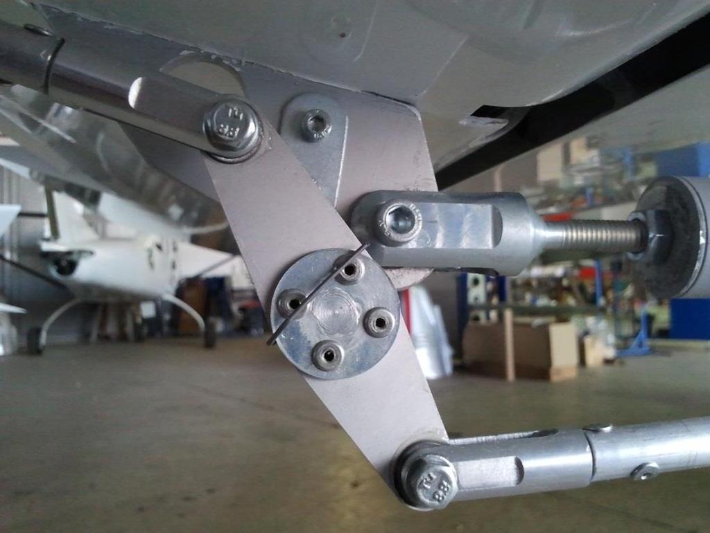
75 3-14
 Tail cone cover.")

76 10) Trim tab deflection. Check angles of deflection of the Trim tab. Check Trim tab neutral position. Inspect Trim tab for free travel. 11) Tail cone cover. Fix Tail cone cover on the fuselage with twelve slotted mushroom head screws M4 x 12 (905624). Two screws are under the horizontal tail stabilizer and two screws are in the fuselage accessible through the rear inspection hole. See the Picture below. Insert screwdriver in the fuselage as shown for screw bold holding the tail cover. 3-15

77 3-16

78 3.3.2 Horizontal tail removal The rest of the horizontal tail removal process goes in reverse to the horizontal tail installation process Elevator installation To installation the elevator requires two person. Type of Maintenance Line Level of Certification Required L/O, RI, RM, A& P Task Specific Can be completed only by a responsible individual, which has received TL-Ultralight Airplane Operation Training. Tools Required Allen wrench 5 (1pcs) Socket wrench 8, 10 (1pcs) Screwdriver (1pcs) Torque wrench (1pcs) Materials Required Self-locking nuts VM3 (2 pcs) Plastic grease Mogul G3 F-900 Torque seal Elevator Installation Checklist 1) Aircraft parking. Prior to installation set the aircraft on the parking brake and remove any obstacle within 8ft area from the rear part of fuselage if you mount elevator on the aircraft with fixed stabilizer. If you install elevator on non on the fuselage fixed stabilizer, put stabilizer on the cradles. 2) Lubricating. Lubricate all elevator hinges (on the stabilizer and elevator) with plastic grease before connecting: Elevator hinges and bearing and bolt on the Elevator drive. 3-17
79 3) Elevator assembly. Insert the elevator with the hinges into the stabilizer from the back side. 4) Elevator assembly. Fix the Elevator on the Stabilizator with five elevator pins. Use only castle nut M6 with the cotter pin 1,

80 5) Elevator control connection. Connect the elevator control connetcion as shown. Use screw M5 x 25 DIN 912 with washer M6 and castle nut with cotter pin 1,
81 6) Elevator deflection. Check angles of deflection of the elevator to within the range as follows (± 10 mm / ± 0.4 in). 7) Fuselage-to-rudder wiring. Connect all fuselage-to-rudder wiring, i.e. connect the position lights sockets and plug. Fix wires in the fuselage as shown. Access to the wires is through the rear inspection hole 3-20
82 8) Trim tab connection. Connect the Trim tab lever with elevator trim tab as shown. Use phil. Head machine screws M3 x 10 DIN Use only new self-locking nuts VM3. 9) Trim tab control connection. Connect the trim tab with trim tab pullrod drive as shown. Use bold M5 x 20 with washers M5 and castle nuts with cotter pin
83 3-22
.")
84 10) Trim tab deflection. Check angles of deflection of the Trim tab. Check Trim tab neutral position. Inspect Trim tab for free travel. 11) Tail cone cover. Fix Tail cone cover on the fuselage with twelve slotted mushroom head screws M4 x 12 (905624). Two screws are under the horizontal tail stabilizer and two screws are in the fuselage accessible through the rear inspection hole. See the Picture below. Insert screwdriver in the fuselage as shown for screw bold holding the tail cover. 3-23

85 12) Rear inspection hole. Close rear inspection hole by screw M4 x 12 (905624) Elevator Removal The rest of the elevator removal process goes in reverse to the wings installation process. 3-24
86 3.3.5 Verification Required (horizontal tail and elevator) Make sure the main bolts are not loose (do not rotate). Check fuselage and horizontal tail for foreign objects. Check elevator and trim tab for free travel. Secure all bolted connections by the F-900 Torque seal Rudder Installation To installation the rudder requires two person. Type of Maintenance Line Level of Certification Required L/O, RI, RM, A& P Task Specific Can be completed only by a responsible individual, which has received TL-Utralight Airplane Operation Training. Tools Required Allen wrench 5 (1pcs) Socket wrench 10 (1pcs) Screwdriver (1pcs) Torque wrench (1pcs) Hook for rudder springs (1pcs) Materials Required Self-locking nuts VM6 (1 pcs) Plastic grease Mogul G3 F-900 Torque seal Rudder Installation Checklist 1) Aircraft parking. Prior to installation set the aircraft on the parking brake and remove any obstacle within 6ft area from the rear part of fuselage. 2) Lubricating. Lubricate rudder upper and bottom hinges with plastic grease before connecting: Bottom mounting axis bearing on the Upper rudder hinge and Upper rudder pin. Pos. Part Part number / Norm 1 Bottom mounting axis s213_100_ Upper rudder hinge s214_100_ Upper rudder pin s214_200_


87 3-26


88 3) Rudder assembly. Slip the small spacer on the bottom mounting axis. Put the rudder on the fuselage inserting the bottom mounting axis to the ball bearing the bottom suspension. Then upper rudder attachment, i.e. slip the upper rudder pin on the bearing in the upper rudder hinge. 3-27


89 3-28

90 4) Rudder balance beam assembly. Slip the Big spacer on the Bottom mounting axis. Fix the Rudder balance beam on the Bottom mounting axis with screw M6 x 30 DIN 912. Use only new self-locking nuts VM
. 5) Rudder spring connection.")
91 Pos. Part Part number / Norm 1 Bottom mounting axis s213_100_ Big spacer s213_400_ Rudder balance beam s213_500_ Screw M6 x 30 DIN Washer M6 ČSN Self locking nut VM 6 DIN 980 CAUTION During the assembly don t damage the fuselage to rudder wiring inside the Bottom mounting axis (especially when inserting the screw M6 x 30). 5) Rudder spring connection. Connect two Rudder springs to the Fuselage bulkhead. Bulkhead is located behind the crew seats. Use hook for springs tension. 3-30
92 6) Fuselage-to-rudder wiring. Connect all fuselage-to-rudder wiring, i.e. connect the position lights sockets and plug. Fix wires in the fuselage as shown. Access to the wires is through the rear inspection hole 7) Rudder deflection. Check angles of deflection of the Rudder to within the range 20 left and right (± 10 mm / ± 0.4 in). Inspect Rudder for free travel. 8) Securing bolted connections. Secure all bolted connections by the F-900 Torque seal. 9) Tail cone cover. Fix Tail cone cover on the fuselage with twelve slotted mushroom head screws M4 x 12 (905624). 3-31
93 10) Central console front covers. Install left and right central console front covers with black phil. pan head machine screw M4 x 12 DIN Rudder Removal The rest of the rudder removal process goes in reverse to the wings installation process Verification Required (rudder) Make sure the main bolts are not loose (do not rotate). Check fuselage for foreign objects. Check elevator, trim tab and rudder for free travel. Secure all bolted connections by the F-900 Torque seal. 3.4 Landing gear Nose gear leg installation To the nose gear leg installation is one person required. Type of Maintenance Line Level of Certification Required L/O, RI, RM, A& P Task Specific Can be completed only by a responsible individual, which has received TL-Ultralight Airplane Operation Training. Tools Required Socket wrench 10, 13, 24 (1pcs, 1pcs, 1pcs) Combination wrench 13 (1pcs) Screwdriver (1pcs) Torque wrench (1pcs) Support for the wing 3-32

94 Materials Required Modified self locking nut M16 (1 pcs) Self-locking nuts VM8 (1 pcs) F-900 Torque seal Nose gear leg Installation Checklist 1) Inserting into the bottom hinge. Nose gear leg slide from the bottom side into the bottom nose leg hinge. Don t forgot under the bottom hinge insert ball bearing. Grease ball bearing and sliding parts. Above the bottom hinge first insert roller bearings, after that balance beam spacer and balance beam. 3-33


95 3-34

 Balance beam screw.")
96 2) Inserting into the upper hinge. The upper part of the nose gear leg insert into the upper nose leg hinge. Under the upper hinge insert the spacer ring. Above upper nose leg hinge screw self-locking nut VM8 DIN 980 with the washer M Pos. Part Part number / Norm 1 Nose gear leg upper hinge s424_000_ Nose gear leg s421_000_00-1 3) Balance beam screw. Screw the balance beam through the hole in the balance beam by screw M6 x 55 DIN 912 and use self-locking nut VM6 DIN 980 with washer M8 ČSN
 Mounting rods.")

97 NOTE Location of the balance beam and preparing the hole for screw in the nose gear leg must be prepared by the hole in the engine firewall before montage start. 4) Mounting rods. Install the tensioner rope control to the balance beam. Screw the tensioner sheets on the both ends of the balance beam, using s screw M6 x 20, crown nut M6 ČSN with washer M6 ŠC with cotter pin. 3-36

98 3.4.2 Nose gear leg removal To the nose gear leg removal process goes in reverse to the nose gear leg installation process Nose gear assembly installation Type of Maintenance Line Level of Certification Required L/O, RI, RM, A& P Task Specific Can be completed only by a responsible individual, which has received TL-Ultralight Airplane Operation Training. Tools Required Wrench 5 (1pcs) Allen wrench 5 (1pcs) Screwdriver (1pcs) Torque wrench (1pcs) Support for the fuselage Materials Required Self-locking nuts VM12 (2 pcs) Plastic grease Mogul G3 F-900 Torque seal 3-37
99 Nose gear assembly Installation Checklist 1) Grease. Grease by plastic grease Mogul G3 the bottom part of the nose gear leg under the bottom attachment. (Part of the nose gear leg with slotted) 2) Spring and cylinder spacer. Into the tube for attaching the fork which is assembled in the assembly, insert the cylinder spacer and steel spring. 3) Fork assembly installation. Fork assembly with nose wheel and with tube for attaching the fork with nose wheel pant slide on the nose gear leg attached in the the upper hinge and in the bottom hinge on the fuselage. Assembly slide on the leg from the bottom side. Pos. Part Part number / Norm 1 Nose gear leg s421_000_ Nose wheel pant sn426_000_ Screw M8 x 55 DIN Washer M8 ČSN Self-locking nut VM8 DIN
100 Fork assembly screw by bold M8 x 55 with self-locking nut with washer. Screw through the milled slot in the fixed part of the nose landing gear leg. NOTE For passage screw through the leg must compress the spring. It is necessary to push down on the fuselage. 4) Check. Push the fuselage to check the functionality of the spring. Check free rotation of nose landing gear leg Nose gear assembly removal To the nose gear assembly remove process goes in reverse to the nose gear assembly installation process The upper attachment installation To installation the upper attachment requires one person 3-39

101 Type of Maintenance Line Level of Certification Required L/O, RI, RM, A& P Task Specific Can be completed only by a responsible individual, which has received TL-Ultralight Airplane Operation Training. Tools Required Socket wrench 10 (1pcs) Combination wrench 10 (1pcs) Screwdriver (1pcs) Torque wrench (1pcs) Support for the fuselage Materials Required Self-locking nuts VM6 (6 pcs) Plastic grease Mogul G3 F-900 Torque seal The upper attachment Installation Checklist 1) Upper attachments. Screw the upper attachment. Use four bolt M6 x 20 ISO 4014 a self-locking nuts VM6 DIN 980 with washers M6 x ČSN

102 Pos. Part Part number / Norm 1 Self-locking nutsvm6 DIN Washer M6 ČSN Nose gear upper attachments s424_000_ Screw M6 x 20 ISO The upper attachment removal To the upper attachment remove process goes in reverse to the upper attachment installation process Nose gear bottom attachment installation To installation the nose gear bottom attachment are requires two persons. Type of Maintenance Line Level of Certification Required L/O, RI, RM, A& P Task Specific Can be completed only by a responsible individual, which has received TL-Ultralight Airplane Operation Training. 3-41
103 Tools Required Socket wrench 10 (1pcs) Combination wrench 10 (1pcs) Screwdriver (1pcs) Torque wrench (1pcs) Support for the fuselage Materials Required Self-locking nuts VM6 (6 pcs) Plastic grease Mogul G3 F-900 Torque seal Bottom attachment Installation Checklist 1) Preparation. Before starting, set the parking brake. Remove cowlings, make sure the tail area is clear. Lift the forward fuselage by pushing down the tail at the over horizontal tail main hinge so that is possible insert the support under engine mount firewall attachment. Insert the support securely under engine mount firewall attachments. CAUTION Do not pushing on the horizontal tail surface. CAUTION Be careful not to touch the rear fuselage of the ground 3-42


104 2) Central console front covers removing. Remove left and right central console front covers fixed by black phil. pan head machine screw M4 x 12 DIN

105 NOTE Place where the mounting hole to Access the screws holding bottom attachment is marked in red. 3) Bottom attachment installation. Fix the Bottom attachment on the fuselage with six screws M6 x 22 ISO Use only new self-locking nuts VM6. Proceed this installation from pilot area (nuts and washers) which was developed by dismounting the Central console. NOTE Nuts and washers are located under the floor in the front part of the pilot cabin (accessible through mounting hole as shown on the picture below). Pos. Part Part number / Norm 1 Bottom attachment s423_000_ Screw M6 x 22 ISO Washer M6 ČSN Self locking nut VM 6 DIN

106 4) Central console front covers. Install back left and right central console front covers with black phil. pan head machine screw M4 x 12 DIN Nose gear bottom attachment removal The nose gear bottom attachment removal process goes in reverse to the bottom attachment installation process. 3-45
107 3.4.9 Fork assembly installation To installation the upper attachment requires one person Type of Maintenance Line Level of Certification Required L/O, RI, RM, A& P Task Specific Can be completed only by a responsible individual, which has received TL-Ultralight Airplane Operation Training. Tools Required Wrench 5 (1pcs) Allen wrench 5 (1pcs) Screwdriver (1pcs) Torque wrench (1pcs) Support for the fuselage Materials Required Self-locking nuts VM8 Plastic grease Mogul G3 F-900 Torque seal Fork assembly Installation Checklist 1) Grease. Grease by plastic grease Mogul G3 the bottom part of the nose gear leg under the bottom attachment. (Part of the nose gear leg with slotted) 2) Spring and cylinder spacer. Into the tube for attaching the fork which is assembled in the assembly, insert the cylinder spacer and steel spring. 3) Fork assembly installation. Fork assembly with nose wheel and with tube for attaching the fork with nose wheel pant slide on the nose gear leg attached in the upper hinge and in the bottom hinge on the fuselage. Assembly slide on the leg from the bottom side. Pos. Part Part number / Norm 1 Nose gear leg s421_000_ Nose wheel pant sn426_000_ Screw M8 x 55 DIN Washer M8 ČSN Self-locking nut VM8 DIN
 Check. Push the fuselage to check the functionality of the spring.")
108 Fork assembly screw by bold M8 x 55 with self-locking nut with washer. Screw through the milled slot in the fixed part of the nose landing gear leg. NOTE For passage screw through the leg must compress the spring. It is necessary to push down on the fuselage. 4) Check. Push the fuselage to check the functionality of the spring. Check free rotation of nose landing gear leg Fork assembly removal The nose gear bottom attachment removal process goes in reverse to the bottom attachment installation process. 3-47

109 Main wheel assembly Installation To installation the main wheel assembly requires two person. Type of Maintenance Line Level of Certification Required L/O, RI, RM, A& P Task Specific Can be completed only by a responsible individual, which has received TL-Ultralight Airplane Operation Training. Tools Required Socket wrench 10, 13, 24 (1pcs, 1pcs, 1pcs) Combination wrench 13 (1pcs) Screwdriver (1pcs) Torque wrench (1pcs) Support for the wing Materials Required Modified self locking nut M16 (1 pcs) Self-locking nuts VM8 (1 pcs) F-900 Torque seal 3-48
110 Main wheel assembly Installation Checklist 1) Preparation. Before starting, set the parking brake. Remove cowlings, make sure the tail area is clear. Lift the forward fuselage by pushing down the tail at the over horizontal tail main hinge so that is possible insert the support under engine mount firewall attachment. Insert the support securely under engine mount firewall attachment. Then, lift up the fuselage and slide under the fuselage prepared support - the cradle. CAUTION When lift the fuselage, pay attention on the elevator. CAUTION During the lift the fuselage, do not touch the elevator. CAUTION Do not lift fuselage via the elevator. 3-49
111 3-50
112 2) Main wheel assembly. Assemble the Main wheel assembly according instructions below. Pos. Part Part number / Norm 1 Main wheel sn411_210_ Brake caliper assembly sn411_220_ Main wheel axis sn411_240_ Brake disc sn411_250_ Main wheel nut sn411_270_ Main wheel nut spacer sn411_280_ Screw M6 x 20 8 Pin 2,5 x 50 ČSN

113 3-52
 Disc caliper axis assembly mount to the main wheel.")
114 3) Disc caliper- axis assembly. Assemble disc caliper axis assembly as shown, it means put the brake disc to the caliper assembly and crew by M6 x 20 to main wheel axis. Bolted connections secured by F900 Torque seal. 4) Disc caliper axis assembly mount to the main wheel. Insert completely assembly into the wheel, it means wheel and main wheel spacer slide on the main wheel axis and attachment wheel nut by the cotter pin 2.5 x 50. 5) Brake disc. Brake disc insert into the slots on the main wheel and secure disc by wire diameter of 1 mm in groove. 3-53
 Rubber edging installation.")
115 6) Check and ensure connections. Screw M6 x 20 and main wheel nut secure with cotter pin 2,5 x 50 secure by F900 Torque seal. Check brake disc wire attachment. Check brake disc free moving along the main wheel axis between the uncompressible brake pads. 7) Rubber edging installation. On the hole for undercarriage leg on the inner part of main wheel pant install rubber edging. 8) Main wheel axis assembly. Pos. Part Part number / Norm 1 Left main undercarriage leg sn411_100_ Wheel assembly, brake disc caliper - assembly, main wheel axis assembly 3 Wedge axis washer sn411_230_ Main wheel axis catering pin sn411_260_ Inner part of wheel pant sn411_520_ Screw M6 x 16 HEX ISO Screw M8 x 62 Allen wrench DIN Screw M8 x 67 Allen wrench DIN Washer M6 ČSN Washer M8 large - 11 Nut M8 self-locking DIN
116 9) Inner main wheel pant installation. Slide the inner part of the main wheel pant to the main undercarriage leg. Put brake hose into the slot on wheel pant. NOTE Inner part of main wheel pant must be strung to the main undercarriage leg before main wheel axis assembly. 10) Install the main wheel axis centering pin. Thread wedge axis washer to main wheel axis catering pin. Insert catering pin into the case in the main undercarriage leg. 11) Main wheel, caliper and axis assembly. Main wheel, caliper and axis assembly screw on undercarriage leg, it means driven throughout the leg two screws M8x62 (upper) and two screws M8x67 (lower, passes throughout the caliper), throughout main wheel, throughout hose in axis assembly and screw it by self-locking nuts M8 with washer M8. Secure by the F900 Torque seal. 12) Inner part of the main wheel pant installation. The inner part of the main wheel pant slide down on the undercarriage leg into correct place and screw by the M6 x 16 with M6 washer. 3-55
117 13) Check freedom of rotation. Check the main wheel free rotation. The wheel must rotate freely without any resistance. 14) Main wheel pant assembly. Assembly inner and outer part of the main wheel pant (as shown), it means spacing tube and washer screw by M6 x 50. Screw inner and outer part of main wheel pant by the 12 screws M4 x 12. Bolted joints secure by the F900 Torque seal. Pos. Part Part number / Norm 1 Main wheel pant spacing tube s411_300_ Outer part of main wheel pant s411_510_ Screw M6 x 50 HEX ISO Washer M6 ČS

118 15) Check freedom of rotation. Check the main wheel free rotation. The wheel must rotate freely without any resistance. Between the main wheel and main wheel pant must be a hole mm. Check strength of attachment main wheel pant Main wheel assembly removal The Main wheel assembly removal process goes in reverse to the Main wheel assembly installation process. After disconnection the line of the Brake system prevent draining of brake liquid out of the hose by plugging it up. 3-57
119 Main undercarriage leg removal To remove the main wheel assembly requires two person. Type of Maintenance Line Level of Certification Required L/O, RI, RM, A& P Task Specific Can be completed only by a responsible individual, which has received TL-Ultralight Airplane Operation Training. Tools Required Socket wrench 10, 13, 24 (1pcs, 1pcs, 1pcs) Combination wrench 13 (1pcs) Screwdriver (1pcs) Torque wrench (1pcs) Support for the wing Materials Required Modified self locking nut M16 (1 pcs) Self-locking nuts VM8 (1 pcs) F-900 Torque seal Main undercarriage leg remove checklist 1) Preparation. Before starting, set the parking brake. Remove cowlings, make sure the tail area is clear. Lift the forward fuselage by pushing down the tail at the over horizontal tail main hinge so that is possible insert the support under engine mount firewall attachment. Insert the support securely under engine mount firewall attachment. Then, lift up the fuselage and slide under the fuselage prepared support - the cradle. CAUTION When lift the fuselage, pay attention on the elevator. CAUTION During the lift the fuselage, do not touch the elevator. CAUTION Do not lift fuselage via the elevator. 3-58
120 3-59
121 2) Seat removal. Remove the Back seat and the Bottom seat over installed main undercarriage leg. See chapter ) Main undercarriage leg removal. Main undercarriage leg is attached in the laminated case. Through the case and leg go two screws M8 x 65 with washers M8 and nuts M8. Unscrew two screws (on each main undercarriage leg). Use hammer and knock out the main undercarriage leg out from the case. Knock just only to the main undercarriage legs and not to the laminate. 3-60

122 CAUTION Knocking only on the place indicated by the arrow 3-61
123 Main undercarriage leg installation Type of Maintenance Line Level of Certification Required L/O, RI, RM, A& P Task Specific Can be completed only by a responsible individual, which has received TL-Ultralight Airplane Operation Training. Tools Required Socket wrench 10, 13, 24 (1pcs, 1pcs, 1pcs) Combination wrench 13 (1pcs) Screwdriver (1pcs) Torque wrench (1pcs) Support for the wing Materials Required Modified self locking nut M16 (1 pcs) Self-locking nuts VM8 (1 pcs) F-900 Torque seal Main wheel leg Installation Checklist 1) Leg installing. Clean end of the main undercarriage leg from the surface color by the brush paper. Insert end of the main undercarriage leg exactly on the position in the laminate case. CAUTION The leg must be exactly at the point where was the original leg. 2) Leg fixation. Fix the main undercarriage leg in the case by the screws M8 x 65 with washers M8 and nuts M
 Make sure the main bolts are not loose (do not rotate).")
124 3) Seat installation. Install the Back seat and the Bottom seat back in the cockpit. leg. 4) Gap clog. Clog the gap between the main undercarriage leg and bottom side of the fuselage using the silicone Verification Required (Landing gear) Make sure the main bolts are not loose (do not rotate). Check fuselage and wheel pants for foreign objects. Check wheels for free travel. Secure all bolted connections by the F-900 Torque seal Brake system description The aircraft has two single-rotor, hydraulically-actuated brakes located on the main landing gear, one on each wheel. Each brake is connected to a brake piston cylinder attached to the toe pedals of the rudder pedals. 3-63
125 When the operator presses the left brake pedal, hydraulic pressure is sent down hydraulic line to the left wheel brake pads, which in turn press on both sides of the rotor. The same process also applies the right brake pedal pressure to the right brake rotor Filling brake system with fluid Type of Maintenance Line Level of Certification Required L/O, RI, RM, A& P Task Specific Can be completed only by a responsible individual, which has received TL-Ultralight Airplane Operation Training. Tools Required Allen wrench 5 (1pcs) Socket wrench 8, 10 (1 pcs, 1pcs) Screwdriver (1pcs) Torque wrench (1pcs) Auxiliary tank Support for the wing Bottle with the stand for brake fluid Materials Required Self-locking nuts VM6 (4 pcs) F-900 Torque seal DOT 4 (or DOT 5, it depends on type of cylinders) Brake fluid 3-64
126 Filling Brake system with Fluid Checklist 1) Preparation. Before starting, set the chocks under the wheels to prevent plane s rolling. Visually check the system for integrity and tightness. Make sure the aircraft is not set on parking brake, i.e. the parking brake valve is open and the handle of the valve is aligned to aircraft longitudinal axle. 2) Outer part of wheel pant removing. Remove the outer part of the main wheel pant from the inner part of the main wheel pant. Outer part of wheel pant is fixed with slotted mushroom head screws M4 x
127 Pos. Part Part number / Norm 1 Main wheel pant spacer s411_300_ Outer part of the main wheel pant s411_510_ Screw M6 x 50 HEX ISO Washer M6 ČSN ) Brake line interruption. Disconnect hoses joints under the wheel pant. Blind disconnected hoses. 4) Brake fluid filling. Fill brake fluid to the Brake fluid reservoir (bottle) on the Engine mount (on the left side). Brake fluid reservoir is the highest point of the system. Use only the correct type of brake fluid. If are mounted the master cylinders AJP or TL type on the pedal assembly, use DOT 4 brake fluid. When are used the brake master cylinders MATCO type, use DOT 5 brake fluid (see the following figures). 3-66


128 CAUTION Brake fluid is an aggressive substance, be careful avoid the contact with composite structure and cabin upholstery, otherwise it would damage them. 3-67
 and hoses end insert into the auxiliary tank so that the brake fluid can freely flow from Brake fluid reservoir through the brake cylinders")
129 5) Left pedal brake cylinder venting. Remove the Brake cylinder from the left Foot pedal assembly (left pilot side for the left wheel line or right pilot side for the right wheel line). Remove blanking from disconnected hoses (blinded in step 3) and hoses end insert into the auxiliary tank so that the brake fluid can freely flow from Brake fluid reservoir through the brake cylinders on the pedals to the auxiliary tank situated under the disconnected hose. Let the brake fluid to flow through the removed brake cylinder and by tilting with the brake cylinder to different positions try to remove any air bubbles from the Brake cylinder. Several times press on the brake toe pedal and try to remove any air bubbles form the brake line. Then install the Brake cylinder back on the Foot pedal assembly. Use only new self-locking nut VM6. Pos. Part Part number / Norm 1 Foot pedal assembly S4-100_000_ Brake cylinder AJP / TL / MATCO 3 Screw M6 x 25 DIN Washer M6 ČSN Self locking nut VM 6 DIN
 and hoses end insert into the auxiliary tank so that the brake fluid can freely flow from Brake fluid reservoir through the brake cylinders")
130 6) Right pedal brake cylinder venting. Remove the Brake from the right Foot pedal assembly (right pilot side for the left right line or left pilot side for the left wheel line). Remove blanking from disconnected hoses (blinded in step 3) and hoses end insert into the auxiliary tank so that the brake fluid can freely flow from Brake fluid reservoir through the brake cylinders on the pedals to the auxiliary tank situated under the disconnected hose. Let the brake fluid to flow through the removed brake cylinder and by tilting with the brake cylinder to different positions try to remove any air bubbles from the Brake cylinder. Several times press on the brake toe pedals and try to remove any air bubbles form the brake line. Then install the Brake cylinder back on the Foot pedal assembly. Use only new self-locking nut VM6. Pos. Part Part number / Norm 1 Foot pedal assembly S4-100_000_ Brake cylinder AJP / TL / MATCO 3 Screw M6 x 25 DIN Washer M6 ČSN Self locking nut VM 6 DIN
131 7) Hose blinding. Under the wheel pant location blind the disconnected brake system hose leading from the parking brake cylinder. 8) Bottle with the stand for brake fluid connection. Connect hose line from the bottle with the stand for brake fluid to under wheel pant disconnected Brake line leading to the main wheel Brake caliper (left pilot side for the left wheel line or right pilot side for the right wheel line). Bottle on the stand must be filled by brake fluid and this bottle must be the highest point of the system. Pos. Part Part number / Norm 1 Brake system line (from disconnected - hose to the wheel Brake caliper) 2 Brake fluid DOT 4 or DOT 5 3 Bottle with the stand for brake fluid - 4 Hose line for brake fluid - 9) Wheel brake system line venting. Remove the Drain bolt M8 from the Brake caliper and let the brake fluid freely flow from Bottle on the stand to the auxiliary tank situated under the Brake caliper drain bolt M8. By tilting with the Brake caliper cylinder to different positions try to remove any air bubbles from the Brake caliper. NOTE Brake caliper is fixed on the wheel assembly. To remove air bubbles is possible gently tilt the aircraft. If this method fails to remove all air bubbles from the Brake caliper is necessary to remove the wheel assembly and just tilt with it. 3-70

132 Then install the Brake caliper drain bolt M8 back on the Brake caliper. 10) Brake line connection. Connect back hoses joints under the wheel pant. NOTE During this operation protect both hoses line against intrusion of air bubbles. If during the hoses connection penetrated air bubbles, remove them. 3-71
133 11) Brake fluid filling. Fill brake fluid to the Brake fluid reservoir (bottle) on the Engine mount (on the left side). Brake fluid reservoir is the highest point of the system. Remove the Drain bolt M8 from the Brake caliper and let again the brake fluid freely flow from Bottle on the stand trough the brake system line to the auxiliary tank situated under the Brake caliper drain bolt M8. Several times press on the brake toe pedals. Then install back the Brake caliper drain bolt M8 and remove bottle with the stand system. 14) Brake system function verification. Check the Brake system function. Check the Parking brake system function. Visually check the system for integrity and tightness. 15) Wheel pants installation. Install back the Outer part of wheel pant. Use F-900 Torque seal for wheel pant screw connections. NOTE Repeat on the other side of the brake system (Second main wheel brake system) Verification Required (Filling Brake System with Fluid) Make sure the main bolts are not loose (do not rotate). Check fuselage and wheel pants for foreign objects. Check wheels and pedals for free travel. Secure all bolted connections by the F-900 Torque seal. 3-72
134 Replacing/removal of the Brake pads To replacing/removal of the Brake pads requires one person. Type of Maintenance Line Level of Certification Required L/O, RI, RM, A& P Task Specific Can be completed only by a responsible individual, which has received TL-Ultralight Airplane Operation Training. Tools Required Socket wrench 10 (1 pcs) Allen wrench (1 pcs ) Screwdriver (1pcs) Torque wrench (1pcs) Needle nose pliers (1pcs) Materials Required F-900 Torque seal Brake pads for replacing Replacing of the Brake pads Checklist 1) Preparation. Remove cowlings, make sure the tail area is clear. Lift the forward fuselage by pushing down the tail at the over horizontal tail main hinge so that is possible insert the support under engine mount firewall attachment. Insert the support securely under engine mount firewall attachment. Then, lift up the fuselage and slide under the fuselage prepared support - the cradle. CAUTION When lift the fuselage, pay attention on the elevator. CAUTION During the lift the fuselage, do not touch the elevator. CAUTION Do not lift fuselage via the elevator. 3-73
135 3-74

136 2) Remove outer part. Unscrew connecting outer and inner part of the main wheel pant. Remove outer part of the main wheel pant. 3-75

 Brake disc remove.")
137 3) Remove inner part. Unscrew the highlighted screw. Slide the inner part of the main wheel pant up to undercarriage leg. 4) Brake disc remove. Cut the wire holding the brake disc. 3-76


138 5) Remove main wheel. Remove cotter pin 2.5 x 50 and unscrew the nut main wheel. Remove main wheel of the main undercarriage leg. NOTE Main wheel assembly axis to leave installed in the leg. NOTE For more information about wheel remove see "Main wheel assembly" chapter. 6) Release brake pads. Unscrew three screws on the caliper as shown below and release the brake pads. 3-77


139 7) Replacing brake pads. Replace old brake pads with new ones. 3-78


140 8) Screw. Complete the caliper assembly. Use the reverse procedure. Screw three screws. 9) Insert brake disc. Insert brake disc between brake pads in caliper. 3-79
141 10) Brake system function verification. Check the Brake system function. Visually check the system for integrity and tightness. 11) Wheel installation. Slide main wheel to the main wheel axis. 12) Attaching brake disc. Attach the brake disc to the wheel by using wire. 13) Install main wheel. Screw wheel on the main wheel axis by the main wheel nut. Insert cotter pin 2.5 x 50. NOTE For more information about wheel remove see "Main wheel assembly" chapter. 14) Install inner part. Download inner part of the main wheel pant back into place. Screw the highlighted screw. 3-80
142 15) Install outer part. Install outer part of the main wheel pant, i.e. screw screws connecting outer and inner part of the main wheel pant. 3-81

143 Verification Required (Replacing/removal of the Brake pads) Make sure the main bolts are not loose (do not rotate). Check wheel pants for foreign objects. Check wheels for free travel. Secure all bolted connections by the F-900 Torque seal. 3-82

144 3.5 Structural control surfaces TL Sting S4 is equipped with electrically operated split flaps on the wing trailing edge. Extending flaps increases the camber of the wing airfoil, thus raising the maximum lift coefficient. TL Sting S4 is equipped with ailerons on the wing trailing edge. The ailerons are used to control the aircraft roll. Both flaps and ailerons are made of carbon top and bottom skins, glass fiber sandwich spars and ribs. 3-83

145 3.5.1 Flap installation To flap installation requires one person Type of Maintenance Line Level of Certification Required L/O, RI, RM, A& P Task Specific Can be completed only by a responsible individual, which has received TL-Ultralight Airplane Operation Training. Tools Required Allen wrench 6 Socket wrench 10 (1 pcs) Torque wrench (1pcs) Materials Required F-900 Torque seal SOUDAL Fix All Classic (single component joint sealant) Flap installation Checklist 1) Lubricating. Lubricate all metal details with plastic grease before connecting: 6 x flap hinge ( hole for bolt on the wing and on the flap ) and bearing in the flaps pull rod assembly. 2) Flap installation. Fix the flap on the wing with six bolts M6 x 45 DIN 912 with washer M6. Use only castle nuts M6 with cotter pin 1,


146 3) Connection flap control. Insert the flap drive into the backdrop drive flap, Stick must fit into the forks as shown below. 3-85
. Inspect stop switches for operating. Inspect all flaps drive line for vibration and free travel. 3.5.2.")
147 4) Flaps deflection. Ensure that flaps equally on each side of the airplane in all configurations. Measure the down deflection on each side. The difference in static deflection should not be greater than 1/8 (3 mm). Inspect stop switches for operating. Inspect all flaps drive line for vibration and free travel Flap Removal The flap removal process goes in reverse to the Flap installation process. Use segmented blade utility knife for Flap pull rod cover removing. Remove the Flap pull rod cover without damaging the wing. 3-86
148 Verification Required (flap installation/removal) Check flaps for free travel. Secure all bolted connections by the F-900 Torque seal Setting Flap Zero Position To Setting Flap Zero position requires one person. Zero position of the Flaps is the position when the flaps are aligned to the center section on fuselage. Type of Maintenance Line Level of Certification Required L/O, RI, RM, A& P Task Specific Can be completed only by a responsible individual, which has received TL-ULTRALIGHT Airplane Operation Training. Tools Required Allen wrench 5 (1 pcs) Socket wrench 10 (1 pcs) Combination wrench 13 (1 pcs) Torque wrench (1pcs) Materials Required F-900 Torque seal SOUDAL Fix All Classic (single component joint sealant) Setting Flap Zero Position Checklist 1) Close flaps and check position. Fully close flaps using FLYBOX. Check position of booth flaps. 2) Check extended position. Set flaps approx. on take-off position. Check flaps deflection. On both flaps measure the value of deflection. a) both measured value of deflection are the same: the flaps are set correctly continue to 4) b) both measured value of deflection are different: continue to 3) 3-87

149 3) Flaps setting: Using the one of the two highlighted forks set correct position of flaps. Flaps with higher measured value set on the same value, which has a flaps with lower measured value. CAUTION Both flaps must have the same deflection. 3-88
 Device powered OFF. Switch A/M switch in the AUTOMATIC position.")
150 4) Close flaps and check position. Fully close flaps using FLYBOX. Check position of booth flaps. 5) Fly Box flaps settings. CAUTION Both flaps must have the same deflection before FlyBox setting. How to save the positions of flaps using an instrument FlyBox 1) Device powered OFF. Switch A/M switch in the AUTOMATIC position. 2) Press and hold the U/D switch in the UP position for 10 seconds until the LED1 and LED4 start flashing. Then release the U/D switch. 3) Make the sequence using the U/D switch: 2 click in the UP position, 2 click in the DOWN position and 1 click in the UP. 4) Now, the first LED is flashing. You can adjust and the flaps in the desired position (using the U/D switch). To save the position, briefly move the A/M switch in the MANUAL and then return in the AUTOMATIC. 5) Now, the second LED is flashing. You can adjust and save the second position in the same way explained in the previous step (U/D switch to adjust then A/M switch to the save position). 6) Repeat again the step for the third and fourth position. The EFC-P will automatically exit from the programming mode and become operative once the last position is correctly saved in memory. 3-89
151 Verification Required (flap Zero position) Check flaps for free travel. Secure all bolted connections by the F-900 Torque seal Aileron installation To aileron installation requires one person. Type of Maintenance Line Level of Certification Required L/O, RI, RM, A& P Task Specific Can be completed only by a responsible individual, which has received TL-Ultralight Airplane Operation Training. Tools Required Allen wrench 5 Socket wrench 10 (1 pcs) Torque wrench (1pcs) Materials Required F-900 Torque seal SOUDAL Fix All Classic (single component joint sealant) Aileron installation Checklist 1) Lubricating. Lubricate all metal details with plastic grease before connecting: Lubricate hinges on the aileron and hinges on the wing (holes for bold) and bearing in the pull rod assembly. 3-90


152 3) Pull rod connecting. Connect the pull rod and aileron drive by the bold M6 x30 DIN 912. Use castle nut M6 with cotter pin 1,6 and 8 washers M6. Assemble as shown bellow. 3-91

153 Pos. Part Part number / Norm 1 Aileron control hinge s110_650_ Pull rod assembly in the aileron s523_600_ Screw M6 x 30 DIN Washer M6 ČSN Castle nut M 6 ČSN Cotter pin 1,6 ČSN
154 4) Ailerons deflection. Check ailerons deflection. Angles of deflection of the aileron are to within the range as follows (± 5 mm / ± 0.2 in). 5) Aileron pull rod cover installing. Fix the Aileron pull rod cover on the Wing with single component joint sealant SOUDAL Fix All Classic. CAUTION Aileron pull rod cover must be placed in order not to interfere Aileron and Pull rod assembly in the aileron movement. Correct Aileron pull rod cover position must be determinated by the test of all possible ailerons positions. 3-93
155 CAUTION Do not support your hands or any subjects on the wing and aileron, as the laminate surface is not proportioned for high area force Aileron Removal The rest of the Aileron removal process goes in reverse to the Aileron installation process. Use segmented blade utility knife for Aileron pull rod cover removing. Remove the Aileron pull rod cover without damaging the wing Verification required (aileron installation/removal) Check aileron for free travel. Secure all bolted connections by the F-900 Torque seal Setting Aileron Zero Position To Setting Aileron Zero position requires one person. Type of Maintenance Line Level of Certification Required L/O, RI, RM, A& P Task Specific Can be completed only by a responsible individual, which has received TL-Ultralight Airplane Operation Training. Tools Required Allen wrench 5 (1 pcs) Socket wrench 10 (1 pcs) Combination wrench 13 (1 pcs) Torque wrench (1pcs) Materials Required F-900 Torque seal SOUDAL Fix All Classic (single component joint sealant) 3-94

156 Setting Aileron Zero Position Checklist 1) Aileron pull rod cover removing. Remove the Aileron pull rod cover from the Wing. Aileron pull rod cover is glued by the single component joint sealant on the wing. Use segmented blade utility knife for Aileron pull rod cover removing. Remove the Aileron pull rod cover without damaging the wing skin. 2) Aileron control disconnecting. Disconnect the Pull rod assembly in the aileron and the Aileron control hinge. Pull rod assembly in the aileron is fixed with screw M6 x 30 DIN 912 and castle nuts M6 ČSN with the Cotter pin 1,6 3-95
 Aileron pull rod setting. Loosen the nut M8 ISO 4032 on the Adjustable eye M8. Select the correct Adjustable eye M8 position so that aileron is in the zero position.")
157 Pos. Part Part number / Norm 1 Aileron control hinge s110_650_ Pull rod assembly in the aileron s523_600_ Screw M6 x 30 DIN Washer M6 ČSN Castle nut M 6 ČSN Cotter pin 1,6 ČSN ) Aileron pull rod setting. Loosen the nut M8 ISO 4032 on the Adjustable eye M8. Select the correct Adjustable eye M8 position so that aileron is in the zero position. Then tighten the nut M8 ISO 4032 on the Adjustable eye M8 (use F-900 Torque seal). Pos. Part Part number / Norm 1 Wing s110_000_ Aileron s110_600_ Pull rod assembly in the aileron s523_600_ Adjustable eye M8 s590_300_ Nut M 6 ISO
158 4) Pull rod connecting. Connect the pull rod and aileron drive by the bold M6 x30 DIN 912. Use castle nut M6 with cotter pin 1,6 and 8 washers M6. Assemble as shown bellow. Pos. Part Part number / Norm 1 Aileron control hinge s110_650_ Pull rod assembly in the aileron s523_600_ Screw M6 x 30 DIN Washer M6 ČSN Castle nut M 6 ČSN Cotter pin 1,6 ČSN
159 5) Pull rod connecting. Connect the pull rod and aileron drive by the bold M6 x30 DIN 912. Use castle nut M6 with cotter pin 1,6 and 8 washers M6. Assemble as shown below. Pos. Part Part number / Norm 1 Aileron control hinge s110_650_ Pull rod assembly in the aileron s523_600_ Screw M6 x 30 DIN Washer M6 ČSN Castle nut M 6 ČSN Cotter pin 1,6 ČSN
160 6) Ailerons deflection. Check ailerons deflection. Angles of deflection of the aileron are to within the range as follows (± 5 mm / ± 0.2 in). 7) Aileron pull rod cover installing. Fix the Aileron pull rod cover on the Wing with single component joint sealant SOUDAL Fix All Classic. 3-99
161 CAUTION Aileron pull rod cover must be placed in order not to interfere Aileron and pull rod assembly in the aileron movement. Correct Aileron pull rod cover position must be determinated by the test of all possible ailerons positions. CAUTION Do not support your hands or any subjects on the wing and aileron, as the laminate surface is not proportioned for high area force Verification Required (aileron Zero position) Check ailerons for free travel. Secure all bolted connections by the F-900 Torque seal
 3) Service instruction fur ROTAX Type 912 und 914 (series) 4) ROTAX service letter Warranty conditions for ROTAX engine types 912 and 914 (series) 5) ROTAX engine Log book CAUTION")
162 3.6 Engine For engine inspection and maintenance refer to original Rotax manuals supplied with the aircraft: 1) Operator s Manual for ROTAX engine Type 912 Series 2) Documentation for ROTAX aircraft engines (CD ROM) 3) Service instruction fur ROTAX Type 912 und 914 (series) 4) ROTAX service letter Warranty conditions for ROTAX engine types 912 and 914 (series) 5) ROTAX engine Log book CAUTION Engine removal, installation and replacement can only done of TL-Ultralight authorized service center
163 3.7 Fuel System The TL-2000 Sting S4 has one main fuel tank in fuselage and can also be equipped with tanks in the wings. Main tank has capacity 20.5 US Gals. Wing tanks, if installed, has a 6 US Gals each

164 NOTE The aircraft could be equipped with two different types of Fuel Shut-Off Valve. Older aircraft models are fitted with two-way valve type 22MB. The latest aircraft are equipped with two-way valve type TL-ultralight

165 3.7.1 Fuel tanks filter inspection/cleaning To inspection/cleaning wing tanks fuel filters requires two persons. Type of Maintenance Line Level of Certification Required L/O, RI, RM, A& P Task Specific Can be completed only by a responsible individual, which has received TL-Ultralight Airplane Operation Training. Tools Required Socket wrench 22 (1 pcs) Torque wrench (1pcs) Materials Required F-900 Torque seal Fuel tanks filters inspection/cleaning Checklist 1) Drain the fuel tanks. Unscrew the drain valve (located on the bottom side of the fuselage under the main fuel tank) to release fuel from the fuel tank. 2) Remove covers. Remove the side covers of the central console. Unscrew all bolts attached side covers. 3) Unscrew the cover. Unscrew all bolts attached cover on the main fuel tank. Take out the fuel tanks filters. 4) Fuel filters inspection/cleaning. Inspect Fuel tank filter] for obstruction and cleanliness. Clean the fuel tank. Replace fuel filter, if damaged
 Screw the drain valve. Screw the drain valve back. 3.7.2. Verification Required (Fuel tanks filters inspection/cleaning) Make sure the main bolts are not loose (do not rotate).")
166 5) Screw the cover. Install back the main fuel tank cover with fuel tanks filters. 6) Install covers. Install back the side covers of the central console. Screw all bolts attached the side covers. 7) Screw the drain valve. Screw the drain valve back Verification Required (Fuel tanks filters inspection/cleaning) Make sure the main bolts are not loose (do not rotate). Check wings and fuel tanks for foreign objects. Inspect fuel system for fuel leak Secure all bolted connections by the F-900 Torque seal

167 3.7.3 Gascolator Inspection/cleaning To inspection/cleaning Gascolator requires one person. Type of Maintenance Line Level of Certification Required L/O, RI, RM, A& P Task Specific Can be completed only by a responsible individual, which has received TL-Ultralight Airplane Operation Training. Tools Required Screwdriver (1pcs) Materials Required Safety wire diameter Gascolator inspection/cleaning Checklist 1) Engine covers removing. Remove Upper cowling and Bottom bowling. 2) Fuel selector valve. Make sure the Fuel Selector Valve is in the off position. 3) Fuel gascolator draining. Drain the Fuel gascolator by the draining vent on the Fuel gascolator tank. Remove all fuel from Fuel gascolator tank. 4) Safety wire removing. Remove the stainless safety wire securing Fuel gascolator tank Nut
 Fuel gascolator inspection/cleaning.")
168 5) Fuel filter tank removing. Remove Fuel filter tank from the Fuel gascolator. Pos. Part Part number / Norm 1 Fuel filter cap ACS Fuel filter sealing ACS Fuel filter tank ACS ) Fuel gascolator inspection/cleaning. Clean Fuel gascolator fuel strainer and sediment bowl. Inspect the Fuel gascolator sealing for condition, replace it if damaged. 7) Fuel filter tank installation. Install back Fuel filter tank from the Fuel gascolator [ACS 10580]. The rest of the Fuel filter tank installation process goes in reverse to the Fuel filter tank removing process (Step 5). 8) Gascolator nut securing. Secure the Fuel gascolator tank Nut by the stainless safety wire having diameter of Pos. Part Part number / Norm 1 Fuel Gascolator ACS Stainless safety wire diameter 3-107
 Make sure the nuts are not loose (do not rotate).")
169 9) Leakage inspection. Make the Fuel Selector Valve to the Left or Right tank position. Inspect Fuel Gascolator for leakage. 10) Cowlings installation. Install back the Upper cowling and Bottom cowling Verification Required (Gascolator Inspection/cleaning) Make sure the nuts are not loose (do not rotate). Check engine and gascolator area for foreign objects. Inspect fuel system for fuel leak. 3.8 Propeller For propeller inspection and maintenance refer to original propeller manufacturer s manuals. CAUTION Propeller removal, installation and replacement can only done of TL-Ultralight or propeller manufacturer authorized service center

170 3.9 Utility systems Heating System To minimize the chances for carbon monoxide entering the cockpit, heated air is drawn from the water radiator not from a heat exchanger on the muffler. Ambient inlet air taken through the radiator is heated and supplied through a control flap into the cockpit by a air hose. The amount of hot air is regulated by the CABIN HEAT knob on the lower throttle quadrant instrument panel. In case that the aircraft is being operated while OAT is more than 20 C dismount the carbon Heating cover and Heating air hose. To dismounting Heating cover and Heating hose one person is required. Type of Maintenance Line Level of Certification Required L/O, RI, RM, A& P Task Specific Can be completed only by a responsible individual, which has received TL-Ultralight Airplane Operation Training. Tools Required Screwdriver (1pcs) Cross-screwdriver (1pcs) Materials Required - Heating cover and Heating hose dismounting Checklist 1) Engine covers removing. Remove Upper bowling and Bottom cowling. 2) Fuel selector valve. Remove two Hose clamp carbon Heating cover and Heating hose from the engine area
 Cowlings installation. Install back the Upper cowling and Bottom bowling.")
171 Pos. Part Part number / Norm 1 Heating flap s700_910_ Heating cover s700_920_ Heating hose - 4 Hose clamp TORRO ) Heating flap inspection. Make sure the Heating flap on the firewall is in closed position. 4) Cowlings installation. Install back the Upper cowling and Bottom bowling. To removal of the Cabin Heat control knob one person is required. Type of Maintenance Line Level of Certification Required L/O, RI, RM, A& P Task Specific Can be completed only by a responsible individual, which has received TL-Ultralight Airplane Operation Training. Tools Required Screwdriver (1pcs) Cross-screwdriver (1pcs) Needle - nose pliers (1pcs) Materials Required
172 Cabin Heat control knob removal Checklist 1) Upper engine cover removing. Remove Upper cowling. 2) Control cable disconnecting. Disconnect the control cable on the control flap lever located on the firewall (on the Heating flap). 3) Nut removing. Remove the nuts thus releasing the heating control knob. 4) Control knob removing. Remove the Heating control knob with cable from the flexible housing. To installation of the Cabin Heat control knob one person is required. Type of Maintenance Line Level of Certification Required L/O, RI, RM, A& P Task Specific Can be completed only by a responsible individual, which has received TL-ultralight Airplane Operation Training. Tools Required Screwdriver (1pcs) Cross-screwdriver (1pcs) Needle - nose pliers (1pcs) Materials Required F-900 Torque seal Cabin Heat control knob installation Checklist 1) Upper engine cover removing. Remove Upper cowling. 2) Control knob inserting. Insert the Cabin Heat control knob into the flexible housing and fasten it from both sides of the lower throttle panel by means of nuts. 3) Control cable connecting. Connect the control cable with control flap lever on the Heating flap. 4) Heat control adjusting. Adjust heat control Venting System Cockpit ventilation is ensured by two rotating scoop air vents located on the canopy. To removal and installation of the cabin air vents one person is required 3-111
 Cabin air vents removal/installation.")
173 Type of Maintenance Line Level of Certification Required L/O, RI, RM, A& P Task Specific Can be completed only by a responsible individual, which has received TL-Ultralight Airplane Operation Training. Tools Required - Materials Required - Cabin air vents removal and installation Checklist 1) Cabin air vents removal/installation. The two rotating air vents mounted in the canopy can be removed or installed by slightly squeezing the interior edge of the vent scoop from the exterior and rotating the scoop slightly as it is removed or replaced. CAUTION This is should be done carefully to not break the plastic scoop Seats The seats of the Sting S4 are fixed and are equipped with an upholstered removable back cushions attached to the cockpit bulkhead by Velcro. The seat bases are attached to the lower cockpit frame
174 To removal and installation of the seats one person is required. Type of Maintenance Line Level of Certification Required L/O, RI, RM, A& P Task Specific Can be completed only by a responsible individual, which has received TL-Ultralight Airplane Operation Training. Tools Required Screwdriver (1pcs) Cross-screwdriver (1pcs) Materials Required - Seat removal Checklist 1) Back seat removing. Remove seat belts. Remove the back seat: back seat is attached to the cockpit bulkhead by Velcro. Slowly break away the back seat from the bulkhead with Velcro and pull up (in direction of arrow) the back seats

175 2) Bottom seat unscrewing. Remove the screws M5 x 16 located in the rear part of the bottom seat
 Bottom seat install. Slide the bottom seat back on the lower cockpit frame in the arrow direction as shown.")
176 3) Remove bottom seat. Slide backwards the bottom seat out from the lower cockpit frame in the direction on arrow. 4) Bottom seat install. Slide the bottom seat back on the lower cockpit frame in the arrow direction as shown

177 5) Bottom seat screw. Screw M5 x 16 is located in the rear part of the bottom seat. Screw the bottom seat


178 6) Back seat installs. Install the back seat: back seat is attached to the cockpit bulkhead by Velcro. Slide the bottom part of the seas in the middle of the cockpit bulkhead and rear part of the bottom seat. Then press the back seat on the cockpit bulkhead to attach. Give back the seat belts Canopy To removal and installation of the seats two persons are required

179 CAUTION Be careful. If the cover fall down and quickly closed, can cause injury. CAUTION With the canopy handled with care. Be careful to do not break. Type of Maintenance Line Level of Certification Required L/O, RI, RM, A& P Task Specific Can be completed only by a responsible individual, which has received TL-Ultralight Airplane Operation Training. Tools Required Allen wrench Materials Required Canopy removal checklist 1) Gas strut removal. Take out the gas struts supporting the canopy


180 2) Unscrew bold. Unscrew two bolds M8 x 40 (with nut M8) attached the canopy in the fuselage


181 3-120
182 3) Canopy removing. Remove carefully canopy from the fuselage. CAUTION With the canopy handled with care. Be careful to do not break. The canopy installation process goes in reverse to the canopy removal process. NOTE Canopy is not designed for frequent assembly and disassembly, so these operations be performed only if necessary
183 3.10 Instruments and Avionics The specific instruments and/or the configuration in which they are arranged may vary slightly from aircraft to aircraft. The magnetic compass is centered on top of the glare shield behind the utility tray. Sting S4 flight instruments are arranged in the basic T configuration on the pilot (left) side of the aircraft. Part of switches can be placed on the ceiling instrument panel. Exceptions can include the absence of a particular instrument or a variation in the order of the instruments due to after market changes Airspeed indicator markings Airspeed indicator speed range markings: MARKING KIAS KCAS SIGNIFICANCE White arc Green arc Yellow arc Full-Flap Operating Range. Lower limit is maximum weight V S0 in landing configuration. Upper limit is maximum speed permissible with flaps extended to stage one (Takeoff) (Approach) setting. Normal Operating Range. Lower limit is maximum weight V S at most forward CG with flaps retracted. Upper limit is maximum structural cruising speed. VCMN Caution Range. Operations must be conducted with caution and only in smooth air Red line Never Exceed Speed. Maximum speed for all operations
184 Engine instruments The Engine Information System (EIS) is the primary display for monitoring engine operation. The EIS displays the following data: RPM, manifold pressure, fuel pressure, oil temperature, oil pressure, 2 cylinder head temperatures, 4 exhaust gas temperatures, voltage, elapsed engine time, and total engine time. Individual input limitations are preprogrammed into the system. If any of these limits are exceeded, a red EIS alert light will illuminate. The EIS data display will then flash the reading that is in alert. NOTE A difference of as much as 200 RPM can exist between the Rotax tachometer and the RPM indication on the EIS. The EIS digital RPM readout is more accurate and should be relied upon when in doubt. Engine manifold pressure is monitored in the AUX1 display on the EIS. The indication interpreted from the remote sensor is displayed in two digits with a decimal point and one more digit (eg 25.5) which is an indication of induction air manifold pressure, and is measured in inches of mercury. Fuel pressure is monitored in the AUX2 display on the EIS. The indication interpreted from the remote sensor is displayed in two digits without a decimal point (eg 35) which is an indication of 3.5 and is measured in pounds per square inch (PSI). Engine Information System (EIS) Setup (1 Nov 05) (L/O,RI,RM,A&P): 1. Hold down both the Next/ACK and Previous buttons at the same time for 5 seconds. The unit will enter the MAIN program set limits mode and the alert light will stay on. 2. The left (Next/Ack) button will now increase the setting (Up) 3. The center (Previous) button will now lower the setting (Down) 4. The right (Display) button will enter the setting and advance to the (Next) setting. 5. Set Contrast at 2 and push Next, 6. Set Max timer to 0 and push Next, 7. Set Max Oil P to 92 and push Next, 8. Set Min Oil P to 30 and push Next, 9. Set Max Oil T to 256 and push Next, 10. Set Max RPM to 5700 and push Next, 11. Set Max Aux 1 to 0 and push Next, 12. Set Min Aux 1 to 0 and push Next, 13. Set Max Aux 2 to 56 and push Next, 14. Set Min Aux 2 to 22 and push Next, 15. Set Max Volt to 14.8 and push Next, 3-123
185 16. Set Min Volt to 11.0 and push Next, 17. Set Max CHT to 238 and push Next, 18. Set Max EGT to 1600 and push Next, 19. Set Display to 3 and push Next. 20. This will then exit the main program. Prior to entering the SECONDARY program mode, you must read the static amount of the Fuel Pressure display with the power on but the engine off and the aux pump off. Example to obtain the setting value for minimum fuel pressure on Aux2Off: 1. Turn on power to the EIS display. Read the EIS number shown for Fuel Pressure (AUX2) with the power on but no fuel pump or engine running. 2. If this number is one digit such as 9, place a decimal in front to read.9. If the number is two digits such as 11, insert a decimal to read Multiply the number shown by 20, such as.9 x 20 = 18. Then subtract 1, the number will always be odd, so the answer is 17 in this example. 4. If the number is 1.1, then the calculation will be 1.1 X 20 = 22, minus 1 = Pitot static system The pitot-static tube is located under the leading edge of the right wing and consists of a ram air duct located inside a cylindrical static air chamber. Total system pressure is sensed through the hole in the pitot-tube face and static pressure is sensed through the holes on the side of the rear part of fuselage. Pressure distribution to individual instruments is received by means of flexible plastic hoses. The tube supplies dynamic ram air pressure to the airspeed indicator, and the static ports supply outside atmospheric pressure to the airspeed indicator, altimeter, mode C encoder, and vertical speed indicator. If installed, the altitude hold portion of the autopilot is also connected to the pitot system. Pos. Part Part number / Norm 1 Pitot static tube attachment in the wing s611_000_ Pitot static tube s612_000_ Pitot static probe Aviatik 3-124

186 To removal and installation of the pitot static tube one persons is required. Type of Maintenance Line Level of Certification Required L/O, RI, RM, A& P Task Specific Can be completed only by a responsible individual, which has received TL-ultralight Airplane Operation Training. Tools Required Screwdriver (1pcs) Linesman s pliers (1pcs) 3-125
187 Materials Required - Pitot static tube removal Checklist 1) Screw removing. Remove the screw attaching the Pitot static tube with Pitot static tube attachment to the wing. 2) Pitot static tube removing. Remove the Pitot static tube by gently pulling front and rotating the tube to expose the total pressure hose. 3) Hose disconnecting. Disconnect the total pressure hose from the Pitot static probe [Aviatik]. Type of Maintenance Line Level of Certification Required L/O, RI, RM, A& P Task Specific Can be completed only by a responsible individual, which has received TL-Ultralight Airplane Operation Training. Tools Required Screwdriver (1pcs) Linesman s pliers (1pcs) Materials Required F-900 Torque seal Pitot static tube installation Checklist 1) Hose inserting. Insert the transparent hose of total pressure line the Pitot static tube. Connect the hose to the outlet of the Pitot static probe and secure it with clamp. WARNING When connecting the pitot static system hose pay increased attention. There must not be any incorrect connection! Connect the hose to the outlet marked P. 2) Pitot static probe inserting. Insert the Pitot static probe in the Pitot - static tube. 3) Pitot static tube mounting. Attach the Pitot static tube by means of the screw through the Pitot static tube attachment protruding from the leading edge of the left wing. Use F-900 Torque seal for screw connection. 4) Pitot static system inspection. Carry out check of pitot static system tightness
188 To inspect pitot static system tightness one persons is required. Type of Maintenance Line Level of Certification Required L/O, RI, RM, A& P Task Specific Can be completed only by a responsible individual, which has received TL-ultralight Airplane Operation Training. Pitot static system tightness inspection Checklist 1) Static pressure line. In the static pressure system create the under pressure by means of an appropriate instrument corresponding to an altitude of 1000 ft indicated on the cockpit altimeter. Drop in the indicated altitude per one minute must not exceed 100 ft. 2) Total pressure line. Create in the total pressure tube, by means of a suitable instrument, an overpressure corresponding to the speed of 120 KT indicated on the ASI. Drop in speed during 3 minutes must not exceed 3 KT Airspeed indicator The airspeed indicator (ASI) is the instrument that displays how fast the aircraft is traveling, in knots, through the air. Ram air pressure and static atmospheric pressure supplied by the pitot tube and static ports are compared by a diaphragm that expands and contracts as the difference between the two varies. Linkages are connected between the diaphragm and the indicator needle gives the operator a visual reading of the indicated airspeed at any given time Altimeter The altimeter (ALT) contains aneroid wafers that expand and contract as atmospheric pressure changes. As altitude increases, the atmospheric pressure decreases, and the aneroid wafers expand. As altitude decreases, the aneroid wafers will contract. Atmospheric pressure is supplied to the altimeter by the static ports on the fuselage. Mechanical linkages attached to the aneroid wafers move the needles on the altimeter face. A knob on the altimeter s face allows the operator to enter the correct barometric pressure into the Kollsman window. NOTE When setting the current barometric pressure in the Kollsman window for the first flight of the day, note the difference between the indicated altitude and the known field elevation. This will give you a correction factor for airborne resetting
189 Vertical speed indicator The vertical speed indicator (VSI) provides the operator with rate of climb and rate of descent. It acts quite similar to the altimeter. Atmospheric pressure is supplied by the static ports on the fuselage, and this air is sent into a holding chamber. However, unlike the altimeter, this chamber also has a metered leak attached to it that allows the pressure inside the chamber to eventually equalize with the pressure outside of the chamber. As the aircraft climbs, pressure decreases and this is displayed by the needle on the VSI as a rate of climb. When the aircraft stops climbing, the metered leak allows the pressures to equalize, and thus the indicator needle returns to zero, or no rate of climb. The same holds true for a descent. The indicator will show a rate of descent so long as the aircraft continues to lose altitude, but will return to zero whenever level flight is reached. Because of the metered leak, there is a small delay in the VSI s indication and a change in altitude may be noted first from the altimeter Magnetic compass The magnetic compass is designed to determine magnetic course of the airplane. The magnetic compass is positioned on the upper glare shield of the instrument panel and consists of a vessel filed with nonfreezing liquid to dampen movement and has a window in the front wall. The compass rose is positioned on the rotary swinging pivot inside the compass. To magnetic compass compensation one person is required. Type of Maintenance Line Level of Certification Required L/O, RI, RM, A& P Task Specific Can be completed only by a responsible individual, which has received TL-Ultralight Airplane Operation Training. Magnetic compass compensation Checklist 1) Preparatory work. Compass compensation must be performed on the approved compass swinging locations, which are at least 300 ft from steel structures, electric leading or over ground or underground steel equipment or objects. If the compass north is westward from magnetic north, the deviation is westward, i.e. negative. If the compass north is eastward from magnetic north, the deviation is eastward, i.e. positive. 2) Turn the airplane to N heading; eliminate the deviation by C screw. 3) Turn the airplane to S heading, reduce any deviation by half value by C screw and write down the corrected heading
190 4) Turn the airplane to E heading, eliminate the deviation by B screw. 5) Turn the airplane to W heading, reduce any deviation by half value by B screw and write down the corrected heading. 6) Enter the individual corrected headings to maintain in the magnetic direction on the compass compensation card and position it in the airplane near the magnetic compass Avionics equipment For specific operational and maintenance instructions, see the manufacturer s manual corresponding to each piece of equipment. NOTE The Garmin 295 GPS internal AA batteries should to be replaced at each annual condition inspection. The battery furnished with the Garmin 396 should be checked at each annual condition inspection and replaced in accordance with the manufacturer s instructions Electrical System The aircraft is equipped with a 12-volt, direct-current electrical system with grounded negative pole. The primary source of electrical energy is provided by the engine mounted interior alternator/generator with total power of 750 W. The internal alternator located at the rear of the engine block will charge the battery up to 13.5 VDC. Power is supplied to the electrical and avionics circuits through a main bus bar located behind center instrument panel, this bus bar is energized anytime the Main switch is ON. Each system is protected by circuit breaker which is permanently on. If some circuit is overloaded, then the circuit breaker disconnects that circuit. The ELT is independent from the aircraft electrical system
191 3-130
192 3-131
193 Two 12 VDC auxiliary power ports are installed in the lower right and left vertical surface of each seat. The ports are directly hot-wired to the battery and can be used to charge the battery without the operator having to connect additional leads directly to the battery. CAUTION Do not attempt to start the engine with a dead battery by using either 12VDC port. The current load will exceed the wire capacity and a fire may result. The Instrument Switch activates all avionics equipment tied into the circuit. This instrument switch should always be in the OFF position before the main switch is turned on or before the main switch is turned off Exterior lighting Main switches on ceiling panel High capacity, anti-collision, safety strobe lights are located on each wingtip and one on the lower aft tail. These lights are encased in a clear-plastic, flush-mounted cover for protection and decreased drag. The center or ceiling panel has an ON/OFF circuit breaker-switch (CBS) for the strobe lights. LED high intensity position-navigation lights are mounted on each wing tip and on the rudder trailing edge. The ceiling panel has an ON/OFF circuit breaker-switch (CBS) for the position lights. The HID lamp is used for taxi and landing illumination and is mounted on the left wing leading edge. The ceiling panel has an ON/OFF circuit breaker-switch (CBS) for the landing light. To wing tip lights installation one person is required
194 Type of Maintenance Line Level of Certification Required L/O, RI, RM, A& P Task Specific Can be completed only by a responsible individual, which has received TL-Ultralight Airplane Operation Training. Tools Required Screwdriver (1pcs) Linesman s pliers (1pcs) Materials Required F-900 Torque seal Wing tip lights installation Checklist 1) Light assembling. Assembly the wing tip light as shown. Pos. Part Part number / Norm 1 LED light ring s621_300_ LED light 12V s621_400_ LED light spacer - 4 LED light 12V socket - 5 Strobe light Krčmář 6 Strobe light socket Krčmář 3-133
 LED light 12V.")
 Strobe light.")
195 NOTE Wing tip lights could be mounted according to the customer s requirement. Aircraft could be fitted with various lights. 2) LED light 12V. Mount LED light 12V assembly into the light console. Screw the light by a two black screws. 3) Strobe light. Mount the strobe light assembly into the light console. Screw the strobe light by a two black screws
 Light console installing.")
 Transparency light cover installing. Install the Transparency light cover on the wing tip.")
196 4) Mount landing light. Mount the landing light into the light console. 5) Wing-to-wingtip lights wiring. Connect all wing-to-wing tip light wiring, i.e. connect the lights sockets and plug. 6) Light console installing. Install the light console with lights on the wingtip. Use the Philips pan wood screws 3 x 10 with F900 Torque seal. 7) Transparency light cover installing. Install the Transparency light cover on the wing tip. Use the Philips pan wood screws 3 x 10 with F-900 Torque seal

197 Generator The 600 W generator is a part of the engine which supplies electric current through the rectifier. Regulator supplies electric current of 14 V voltage to onboard network. The maximum of approximately 18 amps is provided by the regulator, but only 14 amps should be considered available for use. Technical parameters of generator: Maximum output power: 600 W at 5500 RPM Technical parameters of rectifier - regulator: Type: electronic Output voltage: 14 ± 0.3 V (000 ± 250 RPM) Range of operation temperatures: min. -13 F max F Weight: 0.6 lbs Circuit breakers and fuses Circuit breakers and fuses are the best protection for electrical loads and malfunctions. The most common form of protection for this aircraft is circuit breakers (CB) and circuit breaker-switches (CBS). The CBs cannot manually be pulled out to disconnect the circuit. If a surge or over-loading amperage is placed on a CB switch, the built-in circuit breaker will open turning the switch off, thus protecting the circuit. After reducing the electrical load, turn the switch back to the ON position to reset the breaker
198 Battery Both the GPS and the Emergency Locator Transmitter (ELT) contain internal batteries, and therefore can be operated when Main switch is OFF. The Garmin 295GPS contains six AA batteries. The ELT contains eight D-cell batteries, as well as one small battery in the remote control panel. All batteries should be replaced at each annual inspection. The Garmin 396GPS contains a rechargeable lithium-ion battery pack. The battery furnished with the Garmin 396 should be checked at each annual condition inspection and replaced in accordance with the manufacturers instructions. The maintenance-free Varta battery or equivalent is installed on firewall. Battery can be charged directly in the airplane after disconnecting from the onboard electrical system. Aircraft Battery Technical Parameters: Voltage 12 V Nominal capacity 24 Ah Weight: 17 lbs Discharging current 1200 ma Maximum loading 200 A Range of operation temperatures -22 F to +122 F Number of cycles, 100% discharging-charging: more than 200 Service life: 4 to 5 years (Service life occurs at 60% of nominal capacity after full charging) 3-137
199 NOTE If the airplane is not used for flight for more than one month, remove the battery from the airplane and store it. Always store the battery fully charged at temperature of 68 F. Daily discharging is less than 0.1 % of battery nominal capacity. Regularly recharge it up to the full capacity once a month. To battery removal one person is required. Type of Maintenance Line Level of Certification Required L/O, RI, RM, A& P Task Specific Can be completed only by a responsible individual, which has received TL-Ultralight Airplane Operation Training. Tools Required Screwdriver (1pcs) Cross-screwdriver (1pcs) Wrench 10 (1pcs) Materials Required - Battery removal Checklist 1) Engine cover removing. Remove Upper bowling. 2) Contacts disconnecting. Disconnect the contacts from the battery. 3) Upper battery holder block. Disconnect the Upper battery holder block i. e. remove two Philips mushroom head screws M4 x 10 ISO

200 Pos. Part Part number / Norm 1 Bottom battery holder s700_710_ Upper battery holder block s700_710_ Battery Varta 12V 8Ah 80A(EN) 4 Screw M4 x 10 ISO ) Battery removing. Remove the battery from the airplane. CAUTION To reduce the chance of personal injury and possible equipment damage, remove the negative wire before removing the positive wire
201 To battery installation one person is required. Type of Maintenance Line Level of Certification Required L/O, RI, RM, A& P Task Specific Can be completed only by a responsible individual, which has received TL-Ultralight Airplane Operation Training. Tools Required Screwdriver (1pcs) Cross-screwdriver (1pcs) Wrench 10 (1pcs) Materials Required Electrical grease for battery contact Battery installation Checklist 1) Battery inserting. Insert the battery into the Battery holder on the firewall 2) Battery fastening. Fasten the battery with fixing the Upper battery holder block so that it cannot move in the Bottom battery holder, i.e. fix the Upper battery holder block with two Philips mushroom head screws M4 x 10 ISO Pos. Part Part number / Norm 1 Bottom battery holder s700_710_ Upper battery holder block s700_710_ Battery Varta 12V 8Ah 80A(EN) 4 Screw M4 x 10 ISO


202 3) Additional contacts. Install the additional electrical contacts to the aircraft electrical system. 4) Contacts corrosion protection. Install electrical grease on the battery contacts to minimize corrosion. 5) Clamps installation. Install the clamps on battery contacts from the aircraft electrical +/- system. 6) Engine cowl installation. Reinstall the Upper bowling
203 WARNING Failure to reconnect the battery connectors properly could result in reversing the polarity of the battery. CAUTION Do not replace the dry cell battery with a wet cell battery. The dry cell battery has the electrolyte immobilized as a paste and the battery can be operated in any random position Inspection and operation checks The satisfactory performance of an aircraft is dependent upon the continued reliability of the electrical system. Damaged wiring or equipment in an aircraft, regardless of how minor it may appear to be, cannot be tolerated. Reliability of the system is proportional to the amount of maintenance received and the knowledge of those who perform such maintenance. It is, therefore, important that maintenance be accomplished using the best techniques and practices to minimize the possibility of failure. Inspect equipment, electrical assemblies, and wiring installations for damage, general condition, and proper functioning to ensure the continued satisfactory operation of the electrical system. Adjust, repair, overhaul, and test electrical equipment and systems in accordance with the recommendations and procedures in the component manufacturer s maintenance instructions. Replace components of the electrical system that are damaged or defective with identical parts from the aircraft manufacturer s approved equipment, or its equivalent to the original in operating characteristics, mechanical strength, and environmental specifications. A list of suggested problems to look for and checks to be performed are: a b c d e f g h Damaged, discolored, or overheated equipment, connections, wiring, and installations. Excessive heat or discoloration at high current carrying connections. Misalignment of electrically driven equipment. Poor electrical bonding (broken, disconnected or corroded bonding strap) and grounding, including evidence of corrosion. Dirty equipment and connections. Improper, broken, inadequately supported wiring and conduit, loose connections of terminals, and loose ferrules. Poor mechanical or cold solder joints. Condition of circuit breaker and fuses
204 i j k l m Insufficient clearance between exposed current carrying parts and ground or poor insulation of exposed terminals. Broken or missing safety wire, broken bundle lacing, cotter pins, etc. Operational check of electrically operated equipment such as motors, inverters, generators, batteries, lights, protective devices, etc. Ensure that ventilation and cooling air passages are clear and unobstructed. Voltage check of system with portable precision equipment Structural Repair Task Specific: can be completed only by a responsible individual, which holds either an FAA Mechanic certificate or an FAA LSA Repairman Certificate plus he (or she) must have received TL Ultralight Structure Repairing course. Otherwise all repairs can only be done at TL Ultralight authorized service centers Repair of Laminate parts Any damage of parts from reinforced plastics with epoxy matrix leads to increased saturation of the matrix with humidity and subsequently to loss of properties. Carry out their repair as soon as possible after the damage has occurred. According to the damage extent, it can be divided into repairs of: 1. small damage 2. medium damage (not more than 10% of part damaged) 1. heavy damage General Epoxy resin mixtures are prepared in a given mass ratio by means of weighing (accuracy of scales 0,002 lb) SMALL DAMAGE (surface defects, not affecting the spars or other structure) Repair of damage just by application of mastic and by varnish repair. 1) Preparatory Sanding For a good adhesion of repair layers it is necessary to carry out surface sanding at the utmost up to the depth of contact with the lower surface of fabric (do not damage). It is necessary to do surface sanding with overrun of 2 from the damage location smoothly to the top layer. It is suitable to do sanding with grain size of 160. Dry Sanding equipment with suction from the sanding area is used. Al2O3 or equivalent (fused corundum) can be used as sanding material
205 2) Dust removing Wipe with clean and dry brush or by a vacuum cleaner. 3) Application of smoothing layer After preparation of mixture and its eventual thickening to enhance the non-curtaining capability (for vertical or lower areas) is performed its application onto the repair area by means of a plastic spatula. For better distribution of deposited material on irregular surface it is possible to form it through the laid PE or PP transparent polyethylene. After proper application the layer is without bubbles. Deposit thickness is given by necessary thickness of surrounding layers (leveling) and ranges from to ½ in one deposit. Manufacturer MGS, A: L285 B: Hardener 285 Type Epoxy Mixing Ratio A:B = 100:40 Delay Process within 50 min (for 0.2kg mixture) Rate of Setting 40% 100% Time of Setting 16hours (32hours) 26hours (72hours) (2hours) Temperature F (62-68 F) F (62-68 F) (176 F) Fillers Aerosil, Microballs 4) Sanding Sanding or eventually sealing the surface is made after setting the mixture and possible tearing of the used polyethylene. It is suitable to start sanding with grain size up to 160 and finish with grain size of at least 400. It is carried out by dry sanding equipment with suction from the sanding area. Al203 or equivalent (fused corundum) can be used as sanding material. Basic material of the part must not be diminished by sanding. NOTE Especially in case of carbon stiffener in the basic part, sanding through up to the stiffener must not occur 5) Finishing MEDIUM DAMAGE Repair of damage by replacing the stiffener part, by mastic and varnish repair. At such repair it is necessary to distinguish type of used stiffener (especially for sanding): C (carbon), rovings of fabric of black color G (glass), rovings from milky white to transparent 3-144
206 1) Preparatory Sanding: For good adhesion of repair layers it is necessary to do sanding up to the depth of damage. It is necessary to do surface sanding from the damage area with overrun at the least 1 for every damaged stiffener layer smoothly up to the top layer and then about 2 for finishing and mastic application. It is convenient to do sanding with sanding material having grain size of 160. It is carried out by dry sanding equipment with suction from sanding area. Al203 or equivalent (fused corundum) can be used as sanding material. 2) Dust removing Dust is removed by wiping with a clean and dry brush or by a vacuum cleaner. 3) Stiffener preparation: For this kind of repairs use the stiffener G (glass) with plain weave, 150g/m2, with surface protection for epoxy resins. Number of needed stiffener layers depends on depth of damage. It is possible to say that each layer of the mentioned fabric represents at proper saturation by matrix resin thickness of Stiffener layers must be prepared (cut out) gradually from the smallest (the lowest) up to the bigger (upper), each with overrun of ¾. 4) Putting layers After preparing lamination mixture, it is applied to the place of repair by means of rigid brush. The first stiffener is laid into the deposit and it is again saturated by brush. Another layer of stiffener is laid and saturated. When putting the last layer it is necessary to pay attention to a proper saturation and compression of stiffeners so that they cannot come up" to the surface and subsequent useless damage at final sanding. For better saturation of the surface by resin and securing against curtaining it is possible to put PE or PP transparent foil across the surface. When applied properly, the layer is without bubbles. Repair thickness should exceed surrounding surface in this phase by about 0,020 to 0,040 for finishing. 5) Sanding Carry out sanding and eventually apply mastic on the surface after setting, eventually tearing of the foil. It is suitable to begin sanding by abrasive with grain size of 160 and finish by grain size of at least 400. Dry Sanding equipment is used with suction from the sanding area. Al2O3 or equivalent can be used as sanding material. It is important not to diminish basic material of the part at sanding
207 HEAVY DAMAGE At such damage the part must be replaced. CAUTION When repairing structural parts, it is necessary to pay attention to timely repair see the text about low of properties at humidity effect. CAUTION When repairing small damage, it is necessary to carefully pay attention not to damage any structural part! 3.13 Painting and Coating Task Specific: can be completed a responsible individual, which holds either an FAA Mechanic certificate or an FAA LSA Repairman Certificate or aircraft owner plus he (or she) must have received TL Ultralight Structure Repairing course Paint repairs Safety rules When working with paints, thinners and solvents follow the following safety rules: 1. it is necessary to follow safety rules for working with flammable and volatile substances 2. working area must be properly aerated 3. it is prohibited to smoke and anyway handle with free fire in a working area 4. use protective working means such as goggles, gloves, respirator, etc. Recommendation for additional surface treatment of the airplane surface CAUTION By applying permanent protective coats weight of airplane is increased and gravity center position is changed. Increase in weight depends on type of coat and its thickness
208 1) Washing and degreasing It is possible to use both organic solvents and water based solvents. CAUTION All paints and solvents must be used only with caution for proper personal and environmental protection and disposal. Organic solvents (acetone, metyetylketone (MEK), benzine, toluene) Applied by spraying on washed surfaces (e.g. mechanical sprayer, jet ejector) or by wiping with wet (by pouring, not by dipping because it would contaminate the whole volume of solvent) textile wad. After applying it, the agent is wiped of by clean absorbing material before solvent evaporation. Advantages: fast and reliable evaporation even from the corners and borders without additional warming Disadvantages: it must be used without other dilution (expensive); not ecological (danger of water contamination); detrimental to health (must be carried out in an aerated area with personal protective means); waste (including dripping from the area) must be eliminated in the incinerating plants. Use: for Al-alloys surfaces, epoxy fiberglass CAUTION These agents must not be used for degreasing parts from plastics (PC -Lexan, PMMA Plexiglass) Water-based agents (emulgation substances, wetting agents) Applied also by spraying onto washed surfaces or by wiping with wet (by pouring and dipping) textile wad. After applying it, let it act for some time (see manufacturers recommendation) and then it is rinsed with clear water (by means of sponge dipped in ample amount of water or water jet). Advantages: (different according to the type of product: it is possible to highly dilute with water (cheap); ecological - waste (including dripping from the surface due to ample amount of water it is necessary to contain it) can be generally eliminated after its additional dilution with water; the least detrimental to health. Disadvantages: slow and unreliable evaporating from corners and borders, additional warming (drying) mostly required imperfect elimination of water results in 3-147
209 wrong adhesion of paint coats; imperfect degreasing of fiberglass parts (not possible to use) Use: for Al-alloys surfaces and plastics 2) Application of primer (paint) In order to reach a uniform resistance to corrosion and smooth surface, carry out this application by means of spraying (air standard gun with the upper vessel, air HVLP gun, airless electric gun). The adjusting of the used gun (given by manufacturer) differs according to the type - air pressure, jet diameter. Primer should be applied in several sprayings (total thickness is not reached at a blow) with defined maximum dwell and total drying time till further treatment or handling. Primer serves especially for anchoring (adhesion to the substrate) the topcoats and can serve also for eliminating irregularities of the surface (function of filer, for sanding). Surface Manufacturer Type Carbon fiber Fiberglass PC (Lexan), PMMA (Plexiglass) 3) Bonding BASF Glasurit (base) Further Components Epoxy BASF Glasurit /2 (hardener) Glasurit (thinner) Surface Mass [lb/inch/ft 2 ] Recom. Thickness [ ] (at it can be also used as filler) Drying (between spraying / total) / 65 F 15 min / 12 hours After total drying of basic coat carry out total bonding of irregularities including repairs of bonding. After drying perform sanding with emery paper with grain size of 240 until the surface is smooth. After sanding clean dust and wipe of with grease remover and perform repairing paint coat by primer (1/3 of coat thickness). 4) Application of top coat In order to reach smooth surface apply the paint coat only by spraying. Topcoat serves especially for creating the coat resistant to weather and external effects for aesthetic rendering of the unit. Considering the higher loading by external effects use top materials, exclusively two-component ones, on the acrylic-polyurethane or polyurethane basis, always with guaranteed adhesiveness to the used base coat (according to manufacturer)
210 SMALL DAMAGE General Small damage is a deterioration of corrosion resistance. At repair the situation is made more difficult by the fact that the substrate for repair coats is not a compact surface of basic material but mostly all coats of surface protection (after sanding), of which not all are suitable for (in ageing stage) for good adhesion of paint coats. Therefore accomplish such repairs only by a verified system. It is suitable to choose a defined edge delimited area (e.g. connection of parts, wing edge) for the scope of the place, which is being repaired transition, is then better blended. In the case that it is not possible to choose the area in this way, it is necessary to take into consideration the higher difficulty of the procedure as for the uniformity of shade and elaboration of coat transition. Sanding For good adhesion of the repair coats it is necessary to carry out sanding of the old paint coat at least up to such depth as the depth of damage. Ground area must be larger from 2 to 4 than damaged area. With two-coat type of the topcoat it is necessary to add at least 2 for the run-out of the top coat. Sanding can be started with abrasive having grain size of max. 160 and finish with grain size of 400. It is made by the grinder equipped with the suction from the area of sanding or by manual sanding under water. Degreasing It is carried out in the same way as in the case of the total spray coat. Application of primer For reaching the satisfactory equal adhesion to carry out a spray coat of the place to be repaired by adhesive interlayer Surface Manufacturer Type Surface weight [lb/inch/ft 2 ] Recomm. Thickness [ ] Drying (total) / 65 F Al-alloys Epoxy fiberglass BASF Glasurit Singlecomponent max 15 min Old paint coats Subsequently the primer is applied according to the table.. Paint coat thickness is given by necessary thickness of surrounding coats (leveling)
211 CAUTION In case that the primer was not removed by the previous step, it is not necessary to apply the primer again. The original ground primer with adhesive intercoat is enough. Actual application of primer will be carried out in the same way as for the total spray-coat Application of top coat Application of the top coat will be carried out by spraying as for the total spray coat with the exception of used thinners and hardeners. Due to the need of smooth transition to the basic surface it is necessary to use so called spraying into the surface" using longer time of drying initiations for a good result of work. FINISH COATINGS COLORS AND NUMBER Paint number: Rabbe, RAL9003, Signal White Silicone number: GE Silicone II, White Paint repairs Method of Verification For final inspection touch the painted (or coated) surfaces of parts. Finished surface must be smooth, no dents or bumps are allowed. Ensure original profile of the treated surfaces, if necessary. Inspect painted surface visually from various viewpoints. No paint runs, unpainted areas are allowed. Quality of polishing must be the same of adjacent areas Securing bolted connections General Bolt/nut joint securing is used in order to prevent from their loosening due to vibration or force action on the connected parts, which could result in the damage of the connected parts. Three ways of bolt joint securing are used on the airplane: safety wire, cotter pin and locking washer Cotter Pins Securing by cotter pin is used for bolts subject to rotation. They are used because they can be removed and reinstalled quickly. The diameter of the cotter pin should be the largest size that will fit the slot in the castle nut or the hole in the bolt. To prevent injury the ends of the cotter pin should be bent over the nut and firmly flat against each face of the nut then rolled and tucked
212 Figure: Securing bolts or castle nuts with a cotter pin. Cotter pin removal is very easy: by means of a flat screwdriver straighten up the bent ends of the cotter pin and take the cotter pin out of the hole with small pliers. CAUTION When securing castle nuts, always use new cotter pins. Shift the new cotter pin into the hole in the bolt and bend the cotter pin ends as shown in Figure above Safety Wire Procedure of bolt joint securing is by stainless steel wire having diameter of Figure: Examples of correct direction for drilled bolt safety wire 3-151
213 The installation of safety wire is not intended to retain bolt or nut torque. It is installed to prevent disengagement of screws, nuts, bolts, and other parts for added safety. Do not confuse aluminum wire with stainless steel wire. Wire should only be stainless steel, do not use common wire or ferrous metal which can rust or be attracted by magnetic portions of the aircraft. Drilled bolts or screws do not need to be safety wired if they are installed with selflocking nuts. Safety wire must be installed in a manner that will prevent the tendency of the part to loosen or rotate. See figure on above. Safety wire ends are a safety hazard unless they are bent under and inward toward the part to avoid sharp or projecting ends. Safety wire must not be nicked, kinked, or mutilated. When cutting off the end of the twisted wire, leave at least four to six completer turns (1/2 to 5/8 ) of wound wire to complete a loop. Figure: Safety wire pliers Figure: Twisting the wire 3-152
214 Figure: Safety wire installation to turnbuckles and swaged terminals Safety wire procedures, alignment and installation are shown below: 1. Adjust the correct position of holes for safety wire. 6. Pull the upper wire through the hole in the other bolt. Hold the wire end by pliers tighten it firm. 2. Pull the safety wire through the hole in one bolt to be secured. 3. Hold the upper end of the wire and wind it around the bolt head and then by the other end of the wire. Make sure that the wire is properly tightened around the head. 7. Hold the free end of wire by hand, bend it around the bolt head and along with the other end twist it counterclockwise. 8. Hold the twisted end by pliers and twist it tight
215 4. Twist the wire to the hole in the next bolt as tight as possible. 9. Bend the end of the wire under the bolt head. 5. Tighten the wire and at the same time continue its twisting until perfectly tightened. The twisted wire can have approximately from 3 to 4 threads on the length of 0, Cut off the surplus wire Inspection of rod ends Cracks and subsequent failures of rod ends usually begin at the thread end near the bearing and adjacent to or under the jam nut. (See figure below) Typical locations for rod end cracks 3-154
216 Inspection of push pull tube connections Elongated holes are especially prevalent in taper-pin holes and bolt holes or at the riveted joints of torque tubes and push-pull rods. (See figure below) Typical locations for elongation of insert holes in push pull tubes Cable inspections Swaged Nicopress clamp installation Cable system Inspections The aircraft uses cable only for the rudders and trim system. These cables are subject to many environmental exterior and interior conditions which can result in deterioration over of a long period of time. Wire or stand breakages is easy to visually recognize when bent into a curve. See Figure below. Other deterioration, such as wear, corrosion and distortion are not so easily seen. Therefore the control cables and all critical areas of fatigue, fairleads, pulleys and swaged connections should receive a detailed inspection at the annual condition inspection for signs of such deterioration. Figure: Wire cable strands exposed by bending the cable

217 Figure: Swage terminal shank gauge Nicopress clamp installation procedure is shown below: Pos. Part Part number / Norm 1 Clamp - 2 Eye - 3 Sequence of squeezing - 4 Inspection gauge - 5 Gauge No. - Accomplish all procedures in accordance with the manufacturer directions. First pull the cable through the clamp, make a loop around the eye and pull the cable end back through the clamp. The cable end should overlap by about 1 ¼ from the clamp after its puling through. The overlapping will ensure that the cable end will not be pulled back into the clamp during the clamp squeezing
CHAPTER 10. WEIGHT AND BALANCE
 9/27/01 AC 43.13-1B CHG 1 CHAPTER 10. WEIGHT AND BALANCE SECTION 1 TERMINOLOGY 10-1. GENERAL. The removal or addition of equipment results in changes to the center of gravity (c.g.). The empty weight of
State of Israel Ministry of Transport Civil Aviation Authority TYPE CERTIFICATE DATA SHEET
 State of Israel Ministry of Transport Civil Aviation Authority TYPE CERTIFICATE DATA SHEET TC number: Revision: Aircraft make: Aircraft model: IA298 New BRM Aero BRISTELL RG This Data Sheet which is part
Liberty Aerospace, Inc. Section 1 SECTION 1 GENERAL TABLE OF CONTENTS
 Liberty Aerospace, Inc. Section 1 SECTION 1 TABLE OF CONTENTS Introduction... 1-3 Airplane Three Views... 1-4 Descriptive Data... 1-5 Engine... 1-5 Propeller... 1-5 Fuel... 1-5 Oil... 1-5 Maximum Certificated
DEPARTMENT OF TRANSPORTATION FEDERAL AVIATION ADMINISTRATION TYPE CERTIFICATE DATA SHEET NO. A49NM
 DEPARTMENT OF TRANSPORTATION FEDERAL AVIATION ADMINISTRATION A49NM Jetcruzer 450 June 14, 1994 TYPE CERTIFICATE DATA SHEET NO. A49NM This data sheet which is a part of Type Certificate A49NM, prescribes
Small Fixed Wing Aircraft Operational Weight and Balance Computations
 Small Fixed Wing Aircraft Operational Weight and Balance Computations Chapter 4 Weight and balance data allows the pilot to determine the loaded weight of the aircraft and determine whether or not the
DEPARTMENT OF TRANSPORTATION FEDERAL AVIATION ADMINISTRATION TYPE CERTIFICATE DATA SHEET NO. 1A13
 DEPARTMENT OF TRANSPORTATION FEDERAL AVIATION ADMINISTRATION TYPE CERTIFICATE DATA SHEET NO. 1A13 1A13 Revision 27 Revo, Inc. COLONIAL C-1 COLONIAL C-2 LAKE LA-4 LAKE LA-4A LAKE LA-4P LAKE LA-4-200 LAKE
DEPARTMENT OF TRANSPORTATION FEDERAL AVIATION ADMINISTRATION AIRCRAFT SPECIFICATION NO. A-804. Continental E165-2 (see Item 106 for optional engines)
") DEPARTMENT OF TRANSPORTATION FEDERAL AVIATION ADMINISTRATION A-804 Revision 14 LAND-AIR (TEMCO) (LUSCOMBE) 11A 11E April 6, 2005 AIRCRAFT SPECIFICATION NO. A-804 Type Certificate Holder Luscombe Aircraft
DEPARTMENT OF TRANSPORTATION FEDERAL AVIATION ADMINISTRATION A-804 Revision 14 LAND-AIR (TEMCO) (LUSCOMBE) 11A 11E April 6, 2005 AIRCRAFT SPECIFICATION NO. A-804 Type Certificate Holder Luscombe Aircraft
TYPE-CERTIFICATE DATA SHEET
 TYPE-CERTIFICATE DATA SHEET NO. EASA.IM.A.073 for Beechcraft 390 (PREMIER I and IA) Type Certificate Holder: Textron Aviation Inc. One Cessna Boulevard Wichita, Kansas 67215 USA For Models: Model 390 1
DEPARTMENT OF TRANSPORTATION FEDERAL AVIATION ADMINISTRATION TYPE CERTIFICATE DATA SHEET A18SW. San Antonio, Texas
 DEPARTMENT OF TRANSPORTATION FEDERAL AVIATION ADMINISTRATION A18SW Revision 2 Fairchild Aircraft, Inc. SA227-CC SA227-DC (C-26B) November 14, 1996 TYPE CERTIFICATE DATA SHEET A18SW Type Certificate Holder:
CHAPTER 4 AIRWORTHINESS LIMITATIONS
 Section Title CHAPTER 4 AIRWORTHINESS LIMITATIONS 4-10 Airworthiness Limitations..................................... 4.1 4-20 Additional Limitations....................................... 4.3 4-21 Parts
Hawker Beechcraft Corporation on March 26, 2007
 DEPARTMENT OF TRANSPORTATION FEDERAL AVIATION ADMINISTRATION A00010WI Revision 8 Hawker Beechcraft 390 March 26, 2007 TYPE CERTIFICATE DATA SHEET NO. A00010WI This data sheet, which is part of Type Certificate
DEPARTMENT OF TRANSPORTATION FEDERAL AVIATION ADMINISTRATION. TYPE CERTIFICATE DATA SHEET No. A50NM
 DEPARTMENT OF TRANSPORTATION FEDERAL AVIATION ADMINISTRATION A50NM Dassault Aviation Falcon 2000 December 19, 1995 TYPE CERTIFICATE DATA SHEET No. A50NM This data sheet which is part of Type Certificate
DEPARTMENT OF TRANSPORTATION FEDERAL AVIATION ADMINISTRATION TYPE CERTIFICATE DATA SHEET NO. A33EU
 DEPARTMENT OF TRANSPORTATION FEDERAL AVIATION ADMINISTRATION A33EU Revision 2 DASSAULT-BREGUET Falcon 10 September 3, 1987 TYPE CERTIFICATE DATA SHEET NO. A33EU This data sheet which is a part of Type
TYPE-CERTIFICATE DATA SHEET
 TYPE-CERTIFICATE DATA SHEET NO. EASA.A.607 for BS 115 Type Certificate Holder BLACKSHAPE S.P.A. Strada Statale 16 KM 841+900 70043 Monopoli (BA) ITALY For models: BS 115 TE.CERT.00048-001 European Aviation
CHAPTER 3 LIFE-LIMITED COMPONENTS
 Section Title CHAPTER 3 LIFE-LIMITED COMPONENTS 3.000 Life-Limited Components...................................... 3.1 3.001 Introduction............................................. 3.1 3.002 Time-In-Service
TABLE OF CONTENTS SECTION 6 WEIGHT AND BALANCE
 TABLE OF CONTENTS Paragraph No. Page No. 6.1 General 6-1 6.3 Airplane Weighing Procedure 6-2 6.5 Weight and Balance Data and Record... 6-6 6.7 Weight and Balance Determination for Flight 6-11 Equipment
DEPARTMENT OF TRANSPORTATION FEDERAL AVIATION ADMINISTRATION TYPE CERTIFICATE DATA SHEET NO. A16EA
 DEPARTMENT OF TRANSPORTATION FEDERAL AVIATION ADMINISTRATION A16EA Revision 15 True Flight Holdings LLC AA-5, AA-5A, AA-5B AG-5B September 18, 2009 TYPE CERTIFICATE DATA SHEET NO. A16EA This data sheet,
SECTION 6 WEIGHT & BALANCE/EQUIPMENT LIST
 SECTION 6 WEIGHT AND BALANCE / EQUIPMENT LIST TABLE OF CONTENTS Page Introduction... 6-3 Airplane Weighing Procedures... 6-4 Airplane Weighing Form... 6-5 Weight and Balance... 6-7 Sample Weight and Balance
Hamilton. Hamilton. Jet A/A1 (See Approved Flight Manual for additional fuels) Engine Limits: Gas Gen RPM % Ng (2006)
 Engine Limits: Gas Gen RPM % Ng (2006)") TCDS No A-14 Revision 16 Pacific Aerospace Ltd 750XL 14 June 2018 TYPE CERTIFICATE DATA SHEET No A-14 This data sheet which is part of Type Certificate No A-14 prescribes the conditions and limitations
TCDS No A-14 Revision 16 Pacific Aerospace Ltd 750XL 14 June 2018 TYPE CERTIFICATE DATA SHEET No A-14 This data sheet which is part of Type Certificate No A-14 prescribes the conditions and limitations
SECTION 6 WEIGHT & BALANCE/EQUIPMENT LIST
 SECTION 6 WEIGHT AND BALANCE / EQUIPMENT LIST TABLE OF CONTENTS Page Introduction... 6-3 Airplane Weighing Procedures... 6-4 Airplane Weighing Form... 6-5 Sample Weight and Balance Record... 6-8 Loading
European Aviation Safety Agency
 Page 1/8 European Aviation Safety Agency EASA TYPE CERTIFICATE DATA SHEET Cirrus Design SF50 Type Certificate Holder: Cirrus Design Corporation 4515 Taylor Circle Duluth, Minnesota 55811 United States
JODEL D.112 INFORMATION MANUAL C-FVOF
 JODEL D.112 INFORMATION MANUAL C-FVOF Table of Contents I General Description...4 Dimensions:...4 Powertrain:...4 Landing gear:...4 Control travel:...4 II Limitations...5 Speed limits:...5 Airpeed indicator
European Aviation Safety Agency
 Page 1 of 9 European Aviation Safety Agency EASA TYPE-CERTIFICATE DATA SHEET APM 20 and APM 30 series Type Certificate Holder: BP 1 Manufacturer: BP 1 For variants: APM 20 APM 30 Issue 3 : 23 December
Weight & Balance. Let s Wait & Balance. Chapter Sixteen. Page P1. Excessive Weight and Structural Damage. Center of Gravity
 Page P1 Chapter Sixteen Weight & Balance Let s Wait & Balance Excessive Weight and Structural Damage 1. [P2/1/1] Airplanes are designed to be flown up to a specific maximum weight. A. landing B. gross
CIVIL AVIATION AUTHORITY SAFETY AND AIRSPACE REGULATION GROUP MICROLIGHT TYPE APPROVAL DATA SHEET (TADS) NO: BM-82 ISSUE: 2
 NO: BM-82 ISSUE: 2") TYPE: EV-97 Eurostar SL Microlight (1) MANUFACTURER: Light Sport Aviation Ltd, Wycombe Air Park, Hangar 1, Booker, Marlow, Buckinghamshire, SL7 3DP (2) UK IMPORTER: N/A (3) CERTIFICATION: BCAR Section
TYPE: EV-97 Eurostar SL Microlight (1) MANUFACTURER: Light Sport Aviation Ltd, Wycombe Air Park, Hangar 1, Booker, Marlow, Buckinghamshire, SL7 3DP (2) UK IMPORTER: N/A (3) CERTIFICATION: BCAR Section
European Aviation Safety Agency
 TCDS No. EASA.A.592 SportStar RTC Page 1 of 8 European Aviation Safety Agency EASA TYPE-CERTIFICATE DATA SHEET EASA.A.592 SportStar RTC Type Certificate Holder: Evektor, spol. s r.o. Letecká 1008 686 04
Accident Prevention Program
 Accident Prevention Program Maintenance Aspects of Owning Your Own Airplane Introduction As an owner-pilot, FAR Part 43 allows you to perform certain types of inspections and maintenance on your airplane.
CHAPTER 3 LIFE-LIMITED COMPONENTS
 CHAPTER 3 LIFE-LIMITED COMPONENTS Section Title 3.100 Life-Limited Components..................................... 3.1 3.110 Time-in-Service Records................................... 3.1 3.120 Fatigue
CIVIL AVIATION AUTHORITY SAFETY REGULATION GROUP MICROLIGHT TYPE APPROVAL DATA SHEET (TADS) NO: BM65 ISSUE: 6. Flight Design CT2K
 NO: BM65 ISSUE: 6. Flight Design CT2K") TYPE: Flight Design CT2K (1) MANUFACTURER: P&M Aviation Ltd, Unit B, Crawford St, Rochdale. (UK type approval holder for Flight Design GMBH) (2) UK IMPORTER: P&M Aviation Ltd. (3) CERTIFICATION: BCAR section
TYPE: Flight Design CT2K (1) MANUFACTURER: P&M Aviation Ltd, Unit B, Crawford St, Rochdale. (UK type approval holder for Flight Design GMBH) (2) UK IMPORTER: P&M Aviation Ltd. (3) CERTIFICATION: BCAR section
LANCAIR LEGACY PRE-TEST FLIGHT INSPECTION (8-04)
") LANCAIR LEGACY PRE-TEST FLIGHT INSPECTION (8-04) OWNER PHONE # ADDRESS N SERIAL # AIRCRAFT TYPE DATE / / TACH TIME hrs. TOTAL TIME hrs. EMPTY WEIGHT CG. PAINT & INTERIOR? YES NO ENGINE TYPE PROPELLER ALL
LANCAIR LEGACY PRE-TEST FLIGHT INSPECTION (8-04) OWNER PHONE # ADDRESS N SERIAL # AIRCRAFT TYPE DATE / / TACH TIME hrs. TOTAL TIME hrs. EMPTY WEIGHT CG. PAINT & INTERIOR? YES NO ENGINE TYPE PROPELLER ALL
Civil Aviation Authority Czech Republic
 TCDS 92-01 L 13 SL Vivat Page 1 of 12 Civil Aviation Authority Czech Republic CAA CZ TYPE-CERTIFICATE DATA SHEET L 13 SL Vivat Type Certificate Holder: EVEKTOR, spol. s r.o. Letecká 1008 CZECH REPUBLIC
TYPE-CERTIFICATE DATA SHEET
 TYPE-CERTIFICATE DATA SHEET NO. EASA.A.598 for Breezer B600 Certificate Holder Breezer Aircraft GmbH & Co. KG Sönke-Nissen-Koog 58 25821 Reußenköge Germany For models: B600 TE.CERT.000xx-001 European Aviation
WEIGHT AND BALANCE FOR CHEROKEE WARRIOR MODEL PA ' ISSUED: MAY 14, 1973 REPORT: VB-535 MODEL: PA
 WEGHT AND BALANCE FOR CHEROKEE WARROR SERAL NO. 28-7415064 28-7415435 N43158 N54446 MODEL PA-28-151' SSUED: MAY 14, 1973 REPORT: VB-535 WEGHT AND BALANCE Log of Revisions.. Weight and Balance Weight and
TYPE-CERTIFICATE DATA SHEET
 TYPE-CERTIFICATE DATA SHEET NO. EASA.A.610 for Type Certificate Holder Game Composites Ltd. Ground Floor Flat 56 Queen s Gate, London, SW7 5JW, United Kingdom For models: TE.CERT.00048-001 European Aviation
TYPE CERTIFICATE DATA SHEET
 TYPE CERTIFICATE DATA SHEET No. EASA.IM.R.121 for Type Certificate Holder Robinson Helicopter Company 2901 Airport Drive Torrance, CA 90505 U.S.A. For Models:, II TE.CERT.00049-001 European Aviation Safety
Section 1.4 FINAL INSPECTION
 File Number MDRA C20 MANUAL of PROCEDURES for INSPECTION of METAL, TUBE, FABRIC and WOOD AMATEUR-BUILT AIRCRAFT, INSPECTION AND TECHNICAL INFORMATION RECORD Section 1.4 FINAL INSPECTION GENERAL 1. Have
European Aviation Safety Agency
 Page 1 of 9 European Aviation Safety Agency EASA TYPE-CERTIFICATE DATA SHEET EASA.A.583 Costruzioni Aeronautiche TECNAM S.r.l. Via Tasso, 478 80127 Napoli ITALIA Issue 01: 27 September 2013 TC issue Issue
TYPE-CERTIFICATE DATA SHEET
 Page 1 of 9 TYPE-CERTIFICATE DATA SHEET EASA.A.583 Costruzioni Aeronautiche TECNAM S.r.l. Via Tasso, 478 80127 Napoli ITALIA EASA Form NR 90 CS-23 Issue 01 Page 2 of 9 CONTENT SECTION A: A.I. General A.II.
European Aviation Safety Agency
 TCDS A.185 P2006T Page 1 of 9 European Aviation Safety Agency EASA TYPE-CERTIFICATE DATA SHEET EASA.A.185 P2006T Type Certificate Holder Costruzioni Aeronautiche TECNAM S.r.l. Via Tasso, 478 80127 Napoli
Van s Aircraft RV-7A. Pilot s Operating Handbook N585RV
 Van s Aircraft RV-7A Pilot s Operating Handbook N585RV PERFORMANCE SPECIFICATIONS SPAN:..25 0 LENGTH...20 4 HEIGHT:.. 7 10 SPEED: Maximum at Sea Level...180 knots Cruise, 75% Power at 8,000 Ft...170 knots
DEPARTMENT OF TRANSPORTATION FEDERAL AVIATION ADMINISTRATION TYPE CERTIFICATE DATA SHEET NO. A13CE
 DEPARTMENT OF TRANSPORTATION FEDERAL AVIATION ADMINISTRATION A13CE Revision 28 CESSNA 177 177A 177B November 16, 2010 TYPE CERTIFICATE DATA SHEET NO. A13CE WARNING: Use of alcohol-based fuels can cause
Chapter 3: Aircraft Construction
 Chapter 3: Aircraft Construction p. 1-3 1. Aircraft Design, Certification, and Airworthiness 1.1. Replace the letters A, B, C, and D by the appropriate name of aircraft component A: B: C: D: E: 1.2. What
T-51 Mustang - 3/4 Scale Kit
 T-51 Mustang - 3/4 Scale Kit Description Titan Aircraft is pleased to offer the T-51D Mustang. This P-51D replica incorporates material and systems not commonly found in comparably priced aircraft. This,
DEPARTMENT OF TRANSPORTATION FEDERAL AVIATION ADMINISTRATION AIRCRAFT SPECIFICATION NO. 5A5
 DEPARTMENT OF TRANSPORTATION FEDERAL AVIATION ADMINISTRATION 5A5 Revision 30 Cessna (USAF 0-1A) 305A (USAF 0-1E) 305C (USAF 0-1G) 305D 305F April 4, 1994 AIRCRAFT SPECIFICATION NO. 5A5 Type Certificate
AIR TRACTOR, INC. OLNEY, TEXAS
 TABLE OF CONTENTS LOG OF REVISIONS... 2 DESCRIPTION... 4 SECTION 1 LIMITATIONS... 5 SECTION 2 NORMAL PROCEDURES... 8 SECTION 3 EMERGENCY PROCEDURES... 8 SECTION 4 MANUFACTURER'S SECTION - PERFORMANCE...
LAA TYPE ACCEPTANCE DATA SHEET TADS 064 STEEN SKYBOLT
 Issue 2 New format. Additional notes on maximum gross weight Revision A Notes added to section 3.4 regarding Marquart Charger undercarriage. Dated 03/01/18 Dated 08/01/18 JV JV This TADS is intended as
European Aviation Safety Agency EASA SPECIFIC AIRWORTHINESS SPECIFICATION. for. OA7 Optica Series 100/200/301
 EASA.SAS.A.073 OA7 Optica Page 1 of 5 European Aviation Safety Agency EASA SPECIFIC AIRWORTHINESS SPECIFICATION for OA7 Optica Series 100/200/301 The UK Type Certificate for this aircraft type is no longer
TYPE-CERTIFICATE DATA SHEET EASA.A.060. Ae 270
 TCDS EASA.A.060 Ae 270 Page 1 of 9 European Aviation Safety Agency EASA TYPE-CERTIFICATE DATA SHEET EASA.A.060 Ae 270 Type Certificate Holder: AIRCRAFT INTEGRATED SOLUTIONS LTD International House 12 Constance
TEMPORARY REVISION NUMBER
 TEMPORARY REVISION NUMBER 7 DATED 1 DECEMBER 2011 MANUAL TITLE MANUAL NUMBER - PAPER COPY TEMPORARY REVISION NUMBER Model 188 & T188 Series 1966 Thru 1984 Service Manual D2054-1-13 D2054-1TR7 MANUAL DATE
European Aviation Safety Agency
 TCDS A.185 Tecnam P2006T Page 1 of 8 European Aviation Safety Agency EASA TYPE-CERTIFICATE DATA SHEET P2006T Type Certificate Holder: Costruzioni Aeronautiche TECNAM S.r.l. Via Tasso, 478 80127 Napoli
DEPARTMENT OF TRANSPORTATION FEDERAL AVIATION ADMINISTRATION AIRCRAFT SPECIFICATION NO. A-725
 DEPARTMENT OF TRANSPORTATION FEDERAL AVIATION ADMINISTRATION A-725 Revision 4 FS 2001 Corp. (Army L-4F) -80 J5B (Army L-4G) J5C March 30, 2001 AIRCRAFT SPECIFICATION NO. A-725 Type Certificate Holder FS
TYPE-CERTIFICATE DATA SHEET
 TYPE-CERTIFICATE DATA SHEET EASA.IM.A.081 for Type Certificate Holder: PACIFIC AEROSPACE Ltd 333 Airport Road, Hamilton 3282, New Zealand For models: TE.CERT.00048-001 European Aviation Safety Agency,
AIRCRAFT INFORMATION. Pipistrel Virus. 80 HP (Rotax 912 UL2) Page 1 MAY 2012, Revision 01
 Page 1 MAY 2012, Revision 01") AIRCRAFT INFORMATION Pipistrel Virus 80 HP (Rotax 912 UL2) Page 1 MAY 2012, Revision 01 www.pipistrel-usa.com info@pipistrel-usa.com Introduction This document is published for the purpose of providing
AIRCRAFT INFORMATION Pipistrel Virus 80 HP (Rotax 912 UL2) Page 1 MAY 2012, Revision 01 www.pipistrel-usa.com info@pipistrel-usa.com Introduction This document is published for the purpose of providing
European Aviation Safety Agency
 TCDS EASA.A.109 ASI AVIATION Page 1 of 10 European Aviation Safety Agency EASA TYPE-CERTIFICATE DATA SHEET EASA.A.109 F 406 Type Certificate Holder : ASI AVIATION 14 allée René Fonck 51100 REIMS France
CHAPTER 18 WEIGHT AND BALANCE
 CHAPTER 18 WEIGHT AND BALANCE Section Title 18-10 Leveling................................................. 18.1 18-11 Leveling at Lower Right Side Frame Tube & Aft Landing Gear Cross Tube.. 18.1 18-12
European Aviation Safety Agency
 TCDS EASA.IM.A.162 Page 1/9 European Aviation Safety Agency EASA TYPE-CERTIFICATE DATA SHEET Tupolev TU 204-120CE Manufacturer: Tupolev PSC 17, Tupolev Embankment 111250 Moscow Russia For model: TU 204-120CE
European Aviation Safety Agency
 TCDS IM.A.226 Cessna Aircraft Company Page 1 of 20 European Aviation Safety Agency EASA TYPE-CERTIFICATE DATA SHEET Cessna Model 208 Type Certificate Holder: Cessna Aircraft Company P.O. Box 7704 Wichita,
REPUBLIC OF INDONESIA MINISTRY OF TRANSPORTATION DIRECTORATE GENERAL OF CIVIL AVIATION TYPE CERTIFICATE DATA SHEET NO. A094
 REPUBLIC OF INDONESIA MINISTRY OF TRANSPORTATION DIRECTORATE GENERAL OF CIVIL AVIATION A094 Revision 0 Costruzioni Aeronautiche TECNAM S.r.L P2006T 7 June 2013 TYPE CERTIFICATE DATA SHEET NO. A094 This
European Aviation Safety Agency
 P2010 Page 1 of 10 European Aviation Safety Agency EASA TYPE-CERTIFICATE DATA SHEET EASA.A.576 P2010 Costruzioni Aeronautiche TECNAM S.r.l. Via Tasso, 478 80127 Napoli ITALIA Issue 01: 26 Sept 2014 Issue
TYPE CERTIFICATE DATA SHEET 2A10
 DEPARTMENT OF TRANSPORTATION FEDERAL AVIATION ADMINISTRATION 2A10 Revision 23 LAVIA S.A. PA-25 PA-25-235 PA-25-260 TYPE CERTIFICATE DATA SHEET 2A10 November 30, 2000 This data sheet which is a part of
European Aviation Safety Agency
 TCDS A.412 Tecnam P92 Page 1 of 13 European Aviation Safety Agency EASA TYPE-CERTIFICATE DATA SHEET EASA.A.412 TECNAM P92 Type Certificate Holder: Costruzioni Aeronautiche TECNAM S.r.l. Via Tasso, 478
DEPARTMENT OF TRANSPORTATION FEDERAL AVIATION ADMINISTRATION TYPE CERTIFICATE DATA SHEET NO. A11EA
 DEPARTMENT OF TRANSPORTATION FEDERAL AVIATION ADMINISTRATION A11EA Revision 9 American General Aircraft Holding Co. AA-1 AA-1A AA-1B AA-1C June 7, 1995 TYPE CERTIFICATE DATA SHEET NO. A11EA This data sheet,
TEMPORARY REVISION NUMBER
 TEMPORARY REVISION NUMBER 8 DATED 1 DECEMBER 2011 MANUAL TITLE MANUAL NUMBER - PAPER COPY TEMPORARY REVISION NUMBER 1978 Thru 1986 Model R182 & TR182 Service Manual D2069-3-13 D2069-3TR8 MANUAL DATE 15
CIVIL AVIATION AUTHORITY SAFETY REGULATION GROUP MICROLIGHT TYPE APPROVAL DATA SHEET (TADS) NO: BM 41 ISSUE: 7
 NO: BM 41 ISSUE: 7") TYPE: Shadow Series CD (1) MANUFACTURER CFM Aircraft Ltd (ceased trading) BMAA is responsible for continued airworthiness (2) UK IMPORTER None (3) CERTIFICATION BCAR Section S (First example Advanced Issue
TYPE: Shadow Series CD (1) MANUFACTURER CFM Aircraft Ltd (ceased trading) BMAA is responsible for continued airworthiness (2) UK IMPORTER None (3) CERTIFICATION BCAR Section S (First example Advanced Issue
CIVIL AVIATION AUTHORITY TYPE APPROVAL DATA SHEET (TADS) NO: BM-84 ISSUE: 1
 NO: BM-84 ISSUE: 1") TYPE: SHERWOOD SCOUT (1) MANUFACTURER: The Light Aircraft Company Limited Hangar 4 Little Snoring Airfield Fakenham Norfolk NR21 0JL (2) UK IMPORTER: N/A (3) CERTIFICATION: BCAR Section S (Issue 6) (4)
TYPE: SHERWOOD SCOUT (1) MANUFACTURER: The Light Aircraft Company Limited Hangar 4 Little Snoring Airfield Fakenham Norfolk NR21 0JL (2) UK IMPORTER: N/A (3) CERTIFICATION: BCAR Section S (Issue 6) (4)
CIVIL AVIATION AUTHORITY SAFETY REGULATION GROUP MICROLIGHT TYPE APPROVAL DATA SHEET (TADS) NO: BM 41 ISSUE: 7. Shadow Series CD
 NO: BM 41 ISSUE: 7. Shadow Series CD") Shadow Series CD 1 MANUFACTURER CFM Aircraft Ltd (ceased trading) BMAA is responsible for continued airworthiness 2 UK IMPORTER None 3 CERTIFICATION BCAR Section S (First example Advanced Issue dated March
Shadow Series CD 1 MANUFACTURER CFM Aircraft Ltd (ceased trading) BMAA is responsible for continued airworthiness 2 UK IMPORTER None 3 CERTIFICATION BCAR Section S (First example Advanced Issue dated March
CIVIL AVIATION AUTHORITY SAFETY REGULATION GROUP MICROLIGHT TYPE APPROVAL DATA SHEET (TADS) NO: BM 55 ISSUE: 6
 NO: BM 55 ISSUE: 6") TYPE: Shadow Series D & DD (1) MANUFACTURER CFM Aircraft Ltd (ceased trading) BMAA is responsible for continued airworthiness (2) UK IMPORTER None (3) CERTIFICATION BCAR Section S (First example Issue
TYPE: Shadow Series D & DD (1) MANUFACTURER CFM Aircraft Ltd (ceased trading) BMAA is responsible for continued airworthiness (2) UK IMPORTER None (3) CERTIFICATION BCAR Section S (First example Issue
DEPARTMENT OF TRANSPORTATION FEDERAL AVIATION ADMINISTRATION AIRCRAFT SPECIFICATION NO. A Fieldbrook Drive Brookfield, Wisconsin 53005
 DEPARTMENT OF TRANSPORTATION FEDERAL AVIATION ADMINISTRATION A-746 Revision 5 TAYLORCRAFT (Army L-2, L-2C) DC-65 (Army L-2E) DF-65 (Army L-2D) DL-65 (Army L-2A, -2B, -2M) DCO-65 April 3, 1972 AIRCRAFT
TYPE CERTIFICATE DATA SHEET
 TYPE CERTIFICATE DATA SHEET No. EASA.IM.R.120 for Type Certificate Holder Robinson Helicopter Company 2901 Airport Drive Torrance, CA 90505 U.S.A. For Models:, Alpha, Beta, Mariner TE.CERT.00049-001 European
DEPARTMENT OF TRANSPORTATION FEDERAL AVIATION ADMINISTRATION TYPE CERTIFICATE DATA SHEET NO. A-761. P. O. Box 37 Rochester, Wisconsin 53167
 DEPARTMENT OF TRANSPORTATION FEDERAL AVIATION ADMINISTRATION TYPE CERTIFICATE DATA SHEET NO. A-761 A-761 Revision 17 American Champion (Bellanca) (Trytek) (Aeronca) 11AC S11AC 11BC S11BC August 1, 1991
Proposed Special Condition C-xx on Rudder Control Reversal Load Conditions. Applicable to Large Aeroplane category. Issue 1
 Proposed Special Condition C-xx on Rudder Control Reversal Load Conditions Introductory note: Applicable to Large Aeroplane category Issue 1 The following Special Condition has been classified as an important
LAA TYPE ACCEPTANCE DATA SHEET TADS 385 BRISTELL NG5 SPEED WING
 Issue 2 Revised elevator trim tab deflections Dated 11/3/15 JV Revision A Amended fuel tank capacity, addition of Dated 7/5/15 JV Jabiru engine, amended agent website address Revision B Correction of Jabiru
DEPARTMENT OF TRANSPORTATION FEDERAL AVIATION ADMINISTRATION RESTRICTED AIRCRAFT SPECIFICATION NO. AR-7
 DEPARTMENT OF TRANSPORTATION FEDERAL AVIATION ADMINISTRATION RESTRICTED AIRCRAFT SPECIFICATION NO. AR-7 AR-7 Revision 10 PIPER PA-18A PA-18A "135" PA-18A "150" April 23, 1996 Type Certificate Holder The
CHAPTER 8 WEIGHT AND BALANCE. Section Title Page
 CHAPTER 8 WEIGHT AND BALANCE Section Title Page 8-10 Leveling.......................................... 8.1 8-11 Leveling for Weight and Balance................. 8.1 8-12 Leveling for Rigging..........................
TYPE CERTIFICATE DATA SHEET 2A8
 DEPARTMENT OF TRANSPORTATION FEDERAL AVIATION ADMINISTRATION TYPE CERTIFICATE DATA SHEET 2A8 2A8 Revision 20 LAVIA S.A. PA-25 PA-25-235 PA-25-260 November 30, 2000 This data sheet which is part of Type
Registration Number. Serial Number
 Registration Number Serial Number This supplement must be attached to the DMCR Approved Airplane Flight Manual listed on page 2 of this supplement or later approved revision and must be carried in the
Shadow Series D & DD
 Shadow Series D & DD 1 MANUFACTURER CFM Aircraft Ltd (ceased trading) BMAA is responsible for continued airworthiness 2 UK IMPORTER None 3 CERTIFICATION BCAR Section S (First example Issue 1 dated April
TYPE-CERTIFICATE DATA SHEET
 TYPE-CERTIFICATE DATA SHEET NO. EASA.A.616 for Type Certificate Holder M&D Flugzeugbau GmbH & Co. KG Streeker Straße 5 b 26446 Friedeburg Germany For models: JS-MD 1C TE.CERT.00135-001 European Union Aviation
European Aviation Safety Agency
 Page 1 of 17 European Aviation Safety Agency EASA TYPE-CERTIFICATE DATA SHEET EASA.A.011 Extra Flugzeugproduktions- und Vertriebs GmbH Schwarze Heide 21 D-46569, Hünxe Germany For models: -500 Issue 24
Changed links from specific to general to account for ever-changing and broken links.
 Flight Training Supplement FTS page iii REV 1: Added the following note to the table of contents "NOTE: Pages 4-7 4-9, 5-7, 5-9, 6-3 and 6-5 correspond to a particular EFIS installation. Please remove
AIRCRAFT INFORMATION. Pipistrel Sinus. 80 HP (Rotax 912 UL2) Page 1 MAY 2012, Revision 01
 Page 1 MAY 2012, Revision 01") AIRCRAFT INFORMATION Pipistrel Sinus 80 HP (Rotax 912 UL2) Page 1 MAY 2012, Revision 01 www.pipistrel-usa.com info@pipistrel-usa.com Introduction This document is published for the purpose of providing
AIRCRAFT INFORMATION Pipistrel Sinus 80 HP (Rotax 912 UL2) Page 1 MAY 2012, Revision 01 www.pipistrel-usa.com info@pipistrel-usa.com Introduction This document is published for the purpose of providing
CIVIL AVIATION AUTHORITY OF THE CZECH REPUBLIC
 CIVIL AVIATION AUTHORITY OF THE CZECH REPUBLIC 74-01 Revision 5 MORAVAN-AEROPLANES a.s. Model Z 726 Model Z 726 K 11.04.2007 TYPE CERTIFICATE DATA SHEET No. 74-01 This data sheet, which is a part of Type
EASA TYPE-CERTIFICATE DATA SHEET EASA.A.113 IAR-46 / -46S
 TCDS EASA.A.113 IAR-46/46S Page 1 of 8 EASA TYPE-CERTIFICATE DATA SHEET EASA.A.113 IAR-46 / -46S Type Certificate Holder: Aeroclubul Romaniei Bd.Lascar Catargiu, Nr.54, cod: 010673 Sector 1, Bucharest
1 Planning Information
 Flight Design GmbH Rudder Centering Fork - Control Stop Replacement 1 Planning Information 1.1 Affected Aircraft Type: Model: Serial Number: Applicable Countries: CT CTLS F-08-04-09, F-08-04-10, F-08-04-11,
INSTRUCTIONS FOR CONTINUED AIRWORTHINESS
 INSTRUCTIONS FOR CONTINUED AIRWORTHINESS INSTALLED IN AIRCRAFT LISTED IN APPROVED MODEL LIST, Issue Date RECORD OF REVISIONS Upon receipt of revisions, insert the revised pages into this document and enter
DO NOT WRITE ON THIS TEST FEB 2013 Elmendorf Aero Club Aircraft Test. Cessna - 182
 DO NOT WRITE ON THIS TEST FEB 2013 Elmendorf Aero Club Aircraft Test Cessna - 182 For the following questions, you will need to refer to the Pilots Information Manual for the C-182R. The bonus questions
TCDS NUMBER E00078NE U.S. DEPARTMENT OF TRANSPORTATION REVISION: 3 DATE: April 12, 2011
 TCDS NUMBER E00078NE U.S. DEPARTMENT OF TRANSPORTATION REVISION: 3 DATE: April 12, 2011 FEDERAL AVIATION ADMINISTRATION GENERAL ELECTRIC COMPANY MODELS: TYPE CERTIFICATE DATA SHEET E00078NE GEnx-1B54 GEnx-1B58
TYPE-CERTIFICATE DATA SHEET
 Issue: 02 Date: 27 October 2017 TYPE-CERTIFICATE DATA SHEET NO. EASA. A.616 for Type Certificate Holder M&D Flugzeugbau GmbH & Co. KG Streeker Straße 5 b 26446 Friedeburg Germany For models: JS-MD 1C TE.CERT.00135-001
Van s Aircraft RV-4. Pilot s Operating Handbook
 Van s Aircraft RV-4 Pilot s Operating Handbook PERFORMANCE SPECIFICATIONS SPAN:.. 23 0 LENGTH:. 19 9 HEIGHT:. 6 8 SPEED: Maximum at Sea Level.. Cruise, 75% Power at 8,000 Ft.. 173 Knots 165 Knots RANGE
Seabee Annual Inspection Procedures
 Procedures Due to the wide variety of Seabee s flying out there, these procedures should be modified to fit YOUR Seabee. Make sure that all AD s are complied with as well as any required Service Bulletins
TYPE-CERTIFICATE DATA SHEET
 SF340A, 340B TYPE-CERTIFICATE DATA SHEET No. EASA.A.068 for SF340A, 340B Type Certificate Holder: Saab AB 581 88 Linköping SWEDEN For Models: SF340A, 340B TE.CERT.00051-001 European Aviation Safety Agency,
European Aviation Safety Agency
 TCDS No.: EASA.IM.A.212 Learjet M60 Page 1 of 15 European Aviation Safety Agency EASA TYPE CERTIFICATE DATA SHEET No. EASA.IM.A.212 for LEARJET Model 60 Type Certificate Holder: Learjet Inc. One Learjet
PIPER CUB J3-65 N68952 PRE-FLIGHT CHECKLIST
 PRE-FLIGHT CHECKLIST COCKPIT Check airworthiness certificate, registration, weight & balance documentation Battery - CONNECTED Plug in headsets or secure as required Fuel ON Primer CLOSED & LOCKED Carb
Author: Ing. M. Zahálka, TL-Ultralight, s.r.o.
 TL-3000 Sirius PILOT OPERATING HANDBOOK 1 February 2011 / Change 4 Aircraft Serial No: Author: Ing. M. Zahálka, TL-Ultralight, s.r.o. This Pilot Operating Handbook must remain in the aircraft and be accessible
[A/C REG. MARK] MAINTENANCE PROGRAM Appendix 6 Revision [No. Date]
![[A/C REG. MARK] MAINTENANCE PROGRAM Appendix 6 Revision [No. Date]](/thumbs/79/79979863.jpg "[A/C REG. MARK] MAINTENANCE PROGRAM Appendix 6 Revision [No. Date]") LIMITED PILOT-OWNER MAINTENANCE (a) Competence and responsibility 1. The Pilot-owner is always responsible for any maintenance that he performs. 2. Before carrying out any Pilot-owner maintenance tasks,
LIMITED PILOT-OWNER MAINTENANCE (a) Competence and responsibility 1. The Pilot-owner is always responsible for any maintenance that he performs. 2. Before carrying out any Pilot-owner maintenance tasks,
European Aviation Safety Agency
 TCDS No. EASA.A.044 L 23 SUPER-BLANÍK Page 1 of 8 European Aviation Safety Agency EASA TYPE-CERTIFICATE DATA SHEET EASA.A.044 L 23 SUPER-BLANÍK Type Certificate Holder: Blanik Aircraft CZ s.r.o. Karolinská
TYPE CERTIFICATE DATA SHEET
 TYPE CERTIFICATE DATA SHEET No. EASA.R.145 for Type Certificate Holder Hélicoptères Guimbal 1070, rue du Lieutenant Parayre Aérodrome d'aix-en-provence 13290 Les Milles France For Model: TE.CERT.00049-001
Type Approval of the Cyclone AX3/503 3 Axis Microlight Aeroplane and Approval for a Permit to Fly
 AIRWORTHINESS APPROVAL NOTE NO: 23042 APPLICANT: AIRCRAFT TYPE: REGISTRATION NO: Cyclone Airsports Ltd Cyclone AX3/503 G-MYER CONSTRUCTOR'S NO: CA 001 Type Approval of the Cyclone AX3/503 3 Axis Microlight
TYPE CERTIFICATE DATA SHEET 2A10
 DEPARTMENT OF TRANSPORTATION FEDERAL AVIATION ADMINISTRATION 2A10 Revision 28 LAVIA ARGENTINA S.A. PA-25 PA-25-235 PA-25-260 TYPE CERTIFICATE DATA SHEET 2A10 July 2, 2013 This data sheet which is a part
CIVIL AVIATION AUTHORITY OF THE CZECH REPUBLIC
 CIVIL AVIATION AUTHORITY OF THE CZECH REPUBLIC 69-04 Revision 6 MORAVAN-AEROPLANES a.s. Model Z 526 F 11.04.2007 TYPE CERTIFICATE DATA SHEET No. 69-04 This data sheet which is a part of Type Certificate