SECTION 6 WEIGHT & BALANCE/EQUIPMENT LIST
|
|
|
- Austin Brooks
- 6 years ago
- Views:
Transcription
1 SECTION 6 WEIGHT AND BALANCE / EQUIPMENT LIST TABLE OF CONTENTS Page Introduction Airplane Weighing Procedures Airplane Weighing Form Weight and Balance Sample Weight and Balance Record Loading Instructions Basic Loading Configuration Aft Seats Weight & Balance Loading Form Loading Graph Center of Gravity Moment Envelope Center of Gravity Range Envelope Carriage of Cargo Cargo Tie-Down Passenger Compartment (Cargo Tie-Down) Baggage Compartment (Cargo Tie-Down) Cabin Height Measurements Door Opening Dimensions Cabin Width Measurements Comprehensive Equipment List ISSUE 2 REV 1 6-1
2 SECTION 6 FOUND INTENTIONALLY LEFT BLANK 6-2 ISSUE 2 February 12, 2012
3 INTRODUCTION This section describes the procedure for establishing the Basic Empty Weight and Moment of the airplane. These procedures involve weighing the airplane and are typically performed by maintenance organizations after major modifications, relocation of equipment, accomplishment of service bulletins, etc. Sample forms are provided for reference in this section. The basic empty weight and centre of gravity of the airplane were established at the factory before delivery of the airplane and this information is provided in the Weight and Balance Record. The procedures for calculating the weight and moment for various operations are also provided in this section. WARNING IT IS THE RESPONSIBILITY OF THE PILOT TO ENSURE THE AIRPLANE IS LOADED PROPERLY. OPERATION OUTSIDE OF PRESCRIBED WEIGHT AND BALANCE LIMITATIONS COULD RESULT IN AN ACCIDENT AND SERIOUS OR FATAL INJURY. NOTE The data in this section utilizes pounds for weight and inches aft of datum for C of G (centre of gravity). ISSUE 2 February 12,
4 SECTION 6 FOUND AIRPLANE WEIGHING PROCEDURES 1. Preparation: a) Inflate tires to recommended operating pressures. b) De-fuel airplane. Refer to FAC2-M200 Maintenance Manual. c) Service engine oil as required to obtain a normal full indication. d) Move sliding seats to the most forward position. e) Raise flaps to the fully retracted position. f) Place all control surfaces in neutral position. g) Remove all non-required items from airplane. 2. Levelling: a) Place scales under each wheel (minimum scale capacity, 1000 pounds each main, 500 pounds nose wheel). b) Deflate the main wheel and/or lower or raise the nose wheel to properly centre the bubble in the level longitudinally and laterally (See Figure 6-1). 3. Weighing: a) With the airplane level and brakes released, record the weight shown on each scale. Deduct the tare, if any, from each reading. 4. Measuring: a) Obtain measurement A in Figure 6-1 by measuring horizontally and parallel to the airplane centre line, from centre of nose wheel axle, left side, to a plumb bob dropped from the line between the main wheel centres. Repeat on right side and average the measurements. 5. Calculate C.G. and Weight: a) Using weights from Item 3 and measurements from Item 4, the airplane Basic Empty Weight and C.G. can be determined by completing the table in Figure 6-1. b) Transfer the basic empty weight and moment data from the table in Figure 6-1 to the Weight and Balance Record, a sample of which is shown in Figure ISSUE 2 February 12, 2012
5 AIRPLANE WEIGHING FORM REFERENCE DATUM: 1/2 in AFT FROM TOP OF LWR HINGE PIN (FRONT DOOR) STN 0.0 IT IS THE RESPONSIBILITY OF THE PILOT TO ENSURE THAT THE AIRPLANE IS PROPERLY LOADED WATERLINE (WL) - INCHES FUSELAGE STATION (FS) - INCHES MEASURE A Measure A per item 4 of this Section, to assist in locating CG with airplane weighed on landing gear LEVELING PROVISIONS Longitudinal & Lateral: Floor of the Passenger Compartment Figure 6-1 Airplane Weighing Form (Sheet 1 of 2) ISSUE 2 February 12,
6 SECTION 6 FOUND Weighing Point Nose Wheel Tare Scale Reading Net Weight Arm Moment (lbs) (lbs) (lbs) (inches) (in lbs) Right Main Left Main Total CG = (Weighed) CG = Total Moment / Total Net Weight Use spaces below to add or subtract items from weighed condition Empty Weight Drainable Unusable Fuel (6lbs/USG) 1.7 USG Basic Empty Weight CG = Net Weight = Scale Reading Tare Moment = Net Weight * Arm Arm is measured from the aircraft datum (See Figure 6 1) Formula for Longitudinal CG (X): X ( Total Weight) - (A Total Weight ) IN. AOD (37.25 Nose Wheel Weight) Figure 6-1 Airplane Weighing Form (Sheet 2 of 2) 6-6 ISSUE 2 February 12, 2012
7 WEIGHT AND BALANCE SAMPLE WEIGHT AND BALANCE RECORD Use this form to maintain a continuous history of changes to the airplane structure or equipment affecting weight and balance. Serial #: Registration: Page of Date ITEM NO. IN OUT Description of Article or Modification Weight Change Added (+) or Removed (-) Weight (lbs) ARM (inch) Moment /1000 Running Basic Empty Weight Weight (lbs) Moment / 1000 ISSUE 2 February 12, 2012 Figure 6-2 Sample Weight and Balance Record 6-7
8 SECTION 6 FOUND LOADING INSTRUCTIONS It is the responsibility of the pilot to ensure that the airplane is properly loaded and operated within the weight and center of gravity limits. The following information will enable you to operate your within these limits. To calculate the weight and balance for a particular loading use the Sample Weight and Balance Loading Form (Figure 6-4), Loading Graph (Figure 6-5), Centre of Gravity and Moment Envelopes (Figure 6-6) and Centre of Gravity Range Envelope (Figure 6-7) as follows: 1. Take the Basic Empty Weight and Moment from appropriate Weight and Balance Record carried in your airplane and enter them on the Weight and Balance Loading Form (Figure 6-4). NOTE The moment which is shown must be divided by 1000 and this value is used as the moment/1000 on the loading form. 2. Use the Loading Graph (Figure 6-5) to determine the moment/1000 for each item (pilot & co-pilot, passengers, fuel, and baggage); then list these on the loading form (Figure 6-4). NOTE Loading Graph information for the pilot, passengers and baggage is based on seats positioned for average occupants and baggage loaded in the centre of the aft baggage compartment. For loadings which differ from these; additional moment calculations, based on the actual weight and C.G. arm (fuselage station) of the item being loaded, must be made if the position of the load is different from that shown in Figure 6-3 Basic Loading Configuration. 3. Sum the weights and moments/1000 (Item 9 in the Figure 6-4 Sample Weight and Balance Loading Form). Plot these values on the Centre of Gravity Moment Envelope (Figure 6-6) and on the Centre of Gravity Range Envelope (Figure 6-7) to determine whether the point falls within the envelope, and see if the loading is acceptable. 6-8 ISSUE 2 February 12, 2012
9 BASIC LOADING CONFIGURATION FUSELAGE STATION (C.G. ARM - INCHES) FS 0.0 Pilot Co Pilot Passenger Compartment *17.8 in (15.8 to 22.8) *** FS 33.5 AFT SEATS * 61.5 (56.0 to 64.0) ***FS 76.0 Baggage Compartment **94 in. FS * Pilot and passenger center of gravity on adjustable seats positioned for average occupant. Numbers in parentheses indicate forward and aft limits of occupant center of gravity range. ** Arm measured to the centre of the area shown. *** The aft door forward edge (approx. stn 33.5) or the forward edge the baggage compartment floor (approx. stn 76.0) can be used as convenient interior points for determining the location. Figure 6-3 Basic Loading Configuration ISSUE 2 February 12,
10 SECTION 6 FOUND AFT SEATS ALLOWABLE AFT SEAT POSITIONS The aft seats are approved for the 9 positions shown below. The first position in figure below is the most aft position on the rail. The seats are to be installed facing forward only SEAT REAR LOCK POSITIONS A/C FWD PASSENGER LOADING, WEIGHT & BALANCE Following is a typical passenger loading table for a passenger weight of 175 lbs and 13.4 lbs seat. Actual passenger weight must be used for actual weight and balance calculation. Centers of gravity of the Passenger and seat locations are shown in the following Table. POSITION 2C3 AFT SEAT LOADING TABLE WEIGHT (lbs) ARM (in AOD) MOMENT (in-lbs/1000) AFT SEAT (ONE 175 LB PERSON & ONE AFT SEAT) = lbs ISSUE 2 February 12, 2012
11 WEIGHT & BALANCE LOADING FORM Serial # : Registration: ITEM 1 Basic Empty Weight DESCRIPTION Includes unusable fuel & oil 2 Front Seat Occupants Pilot and Front Passenger at 22 in. arm for example 3 Rear Seat Occupants Two 200lb 56 in. arm for example 4 Baggage compartment (250 lbs Maximum) in. arm for example Date: SAMPLE AIRPLANE WEIGHT ARM (lbs) (in. AOD) MOMENT (in-lbs / 1000) WEIGHT ARM (lbs) YOUR AIRPLANE (in. AOD) MOMENT (in-lbs / 1000) 5 Zero Fuel Condition Sub total from 1 through Usuable Fuel (6.0 lb/usg) 98 Gallon 21.8 in. Arm in. arm for example 7 Ramp Condition 8 Sub total item 5 & 6 Fuel Allowance for Engine Start, Taxi and Run-Up Normally 2 Gallon ( in. Arm Takeoff Condition Subtract item 8 from 7. For CG (arm), divide Moment by weight. Example: 88800/3751 = Note 1: The takeoff weight in item 9 must not exceed 3800 lbs Note 2: The takeoff condition moment and CG must be within the limits shown in Figure 6-6 and Figure 6-7 at the takeoff weight condition. Figure 6-4 Sample Weight and Balance Loading Form ISSUE 2 February 12,
12 SECTION 6 FOUND LOADING GRAPH Fuel 21.8" Aft Seat: Passenger or 56.0" Pilot & Front 15.8" Pilot & Front 22.8" Aft Seat: Passenger or 64.0" Baggage 94.0" Load Moment / 1000 (in-lbs) Weight (lb) Figure 6-5 Loading Graph 6-12 ISSUE 2 February 12, 2012
13 CENTER OF GRAVITY MOMENT ENVELOPE Airplane Weight (lbs) Airplane Moment / 1000 (in-lbs) Figure 6-6 Centre of Gravity Moment Envelope ISSUE 2 February 12,
14 SECTION 6 FOUND CENTER OF GRAVITY RANGE ENVELOPE Airplane Weight (lbs) Airplane C.G. Location - Aft of Datum (in.) Figure 6-7 Centre of Gravity Range Envelope 6-14 ISSUE 2 February 12, 2012
15 CARRIAGE OF CARGO There are two distinct areas where cargo may be carried (refer to Figure 6-3): The passenger compartment located behind the crew seats (after removal of one or more of the three passenger seats) The baggage compartment located behind the three passenger seats It is recommended that the heaviest cargo be located in the forward part of the airplane and the lightest in the rear part of the airplane in order to keep the centre of gravity within limits. It is essential to properly secure cargo before flight. CARGO TIE-DOWN The airplane is equipped with multiple tie-down points. The load ratings for the tie-down points are given in Figure 6-8. Only the total rated load of the tie-downs located aft of the cargo are to be considered when determining adequate restraint. For example, a 750 lbs load would require a minimum of three tie-downs rated at 250 lbs each to be located aft of the load. It should also be noted that additional tiedowns located forward of the load would also be needed to properly secure the cargo. Rope, strap or cable used for tie-down should be rated at a minimum of ten times the load capacity of the tie-down used. ISSUE 2 REV
16 SECTION 6 FOUND 25 LBS BAGGAGE AREA CREW AREA SECONDARY TIE-DOWNS LOCATED ON SIDEWALL 30 LBS SECONDARY TIE-DOWNS LOCATED ON SIDEWALL PASSENGER AREA SIDE VIEW 100 LBS 125 LBS 125 LBS CREW SEAT TRACKS REAR SEAT TRACKS 250 LBS (DOUBLE STUD) 110 LBS (SINGLE STUD) 125 LBS TOP VIEW Figure 6-8 Tie-down Load Ratings 6-16 ISSUE 2 REV 1


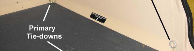
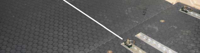
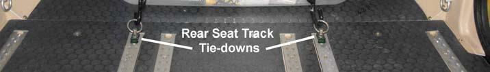
17 PASSENGER COMPARTMENT (CARGO TIE-DOWN) The primary passenger compartment tie-down points are the six rear seat tracks. Tie-down points are created by installing either single or double stud load ring fittings in the tracks. Single Stud Track Fitting Double Stud Track Fitting It should be noted that single stud fittings are typically rated at half the strength of the double stud fittings. Use a double stud fitting to achieve the full strength of the seat track tie-down point. Figure 6-9 shows single stud fittings installed in the rear tracks. ISSUE 2 REV


18 SECTION 6 FOUND Figure 6-9 Single Stud Load Rings in Rear Seat Tracks The rear seat track tie-down points should be used in conjunction with the four tie-down points located at the ends of the crew seat tracks to secure cargo in the passenger compartment. Figure 6-10 shows the location of the tie-down rings on the crew seat tracks. There are four tie-down points located on the sides of the cabin just behind the crew seats. These tie-downs should not be used as the primary tie-down points for securing cargo. They should only be used to stabilize the cargo and prevent it from shifting. Figure 6-11 shows these tie-down points being used in conjunction with the primary tie-down points to secure a cargo bin. There are also six tie-down points located on the sides of the cabin just behind the passenger seats. Again these tie-downs should not be used as the primary attachment points for securing cargo in the passenger compartment. They should only be used in conjunction with the rear seat track tie-down points ISSUE 2 REV 1
19 Figure 6-10 Load Rings on Crew Seats Figure 6-11 shows a cargo bin secured in the passenger compartment using the appropriate tie-down points. There are two (blue) straps running from two rear seat track tie-downs to the tie-downs on the crew seats. A single (orange) strap attached to the outer rear seat tracks tie-downs provides additional forward load capability. Note that this strap has been secured to the top of the cargo bin with an additional strap (blue) to prevent it sliding off the bottom of the bin. A single strap (blue) attached to the tie-downs just aft of the crew seats provides additional stability and helps prevent the cargo bin from sliding aft. In this example there are four tie-downs located aft of the cargo. These tiedowns are single stud fittings in the rear seat tracks with a load rating of 110 lbs each, for a total load rating of 440 lbs. ISSUE 2 REV


20 SECTION 6 FOUND Figure 6-11 Example Cargo Loading in Passenger Compartment Figure 6-12 Horizontal Strap Secured to Prevent Slippage 6-20 ISSUE 2 REV 1


21 BAGGAGE COMPARTMENT (CARGO TIE-DOWN) The maximum load in the baggage compartment is 250 lbs. The primary baggage compartment tie-down points are the D-rings located in the lower aft corners of the compartment, as shown in Figure These two tie-down points should be used in conjunction with tie-down fittings installed in the rear seat tracks to secure cargo in this compartment. Figure 6-15 shows a cargo bin secured using these tie-downs. There are six tie-down points located on the sides of the cabin just behind the passenger seats that may be used in conjunction with the primary tie-downs to stabilize and prevent cargo from shifting. These secondary tie-downs are shown in Figure Figure 6-13 Primary Tie-downs in Baggage Compartment ISSUE 2 REV


22 SECTION 6 FOUND Figure 6-14 Tie-downs in Baggage Compartment 6-22 ISSUE 2 REV 1


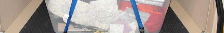
23 Figure 6-15 Cargo Bin Secured in Baggage Compartment ISSUE 2 REV
24 SECTION 6 FOUND CABIN HEIGHT MEASUREMENTS FS 0.0 FS 33.5 FS 76.0 FS 94.0 FS Figure 6-16 Internal Cabin Dimensions 6-24 ISSUE 2 REV 1
25 DOOR OPENING DIMENSIONS Figure 6-17 Door Opening Dimensions ISSUE 2 REV
26 SECTION 6 FOUND CABIN WIDTH MEASUREMENTS FS 0.0 FS 33.5 FS 76.0 FS 94.0 FS Figure 6-18 Cabin Width Measurements 6-26 ISSUE 2 REV 1
27 COMPREHENSIVE EQUIPMENT LIST A comprehensive list of the equipment installed in an airplane is provided with the Pilot s Operating Handbook at the time of delivery. ISSUE 2 REV
SECTION 6 WEIGHT & BALANCE/EQUIPMENT LIST
 SECTION 6 WEIGHT AND BALANCE / EQUIPMENT LIST TABLE OF CONTENTS Page Introduction... 6-3 Airplane Weighing Procedures... 6-4 Airplane Weighing Form... 6-5 Sample Weight and Balance Record... 6-8 Loading
TABLE OF CONTENTS SECTION 6 WEIGHT AND BALANCE
 TABLE OF CONTENTS Paragraph No. Page No. 6.1 General 6-1 6.3 Airplane Weighing Procedure 6-2 6.5 Weight and Balance Data and Record... 6-6 6.7 Weight and Balance Determination for Flight 6-11 Equipment
SECTION VI WEIGHT AND BALANCE/ EQUIPMENT LIST TABLE OF CONTENTS
 BEECHCRAFT Sundowner 180 SECTION VI WEIGHT AND BALANCE/ EQUIPMENT LIST TABLE OF CONTENTS SUBJECT PAGE Introduction To Weight And Balance 6-3 Weighing Instructions 6-4 Basic Weight And Balance Form 6-7
Small Fixed Wing Aircraft Operational Weight and Balance Computations
 Small Fixed Wing Aircraft Operational Weight and Balance Computations Chapter 4 Weight and balance data allows the pilot to determine the loaded weight of the aircraft and determine whether or not the
SECTION 6 WEIGHT AND BALANCE AND EQUIPMENT LIST
 SECTION 6 AND BALANCE AND EQUIPMENT LIST TABLE OF CONTENTS PARAGRAPH PAGE 6.1 GENERAL 6-1 6.2 AIRPLANE WEIGHING PROCEDURES 6-2 6.3 AND BALANCE RECORD 6-10 6.4 AND BALANCE DETERMINATION FOR FLIGHT 6-15
WEIGHT AND BALANCE FOR CHEROKEE WARRIOR MODEL PA ' ISSUED: MAY 14, 1973 REPORT: VB-535 MODEL: PA
 WEGHT AND BALANCE FOR CHEROKEE WARROR SERAL NO. 28-7415064 28-7415435 N43158 N54446 MODEL PA-28-151' SSUED: MAY 14, 1973 REPORT: VB-535 WEGHT AND BALANCE Log of Revisions.. Weight and Balance Weight and
CHAPTER 10. WEIGHT AND BALANCE
 9/27/01 AC 43.13-1B CHG 1 CHAPTER 10. WEIGHT AND BALANCE SECTION 1 TERMINOLOGY 10-1. GENERAL. The removal or addition of equipment results in changes to the center of gravity (c.g.). The empty weight of
Liberty Aerospace, Inc. Section 1 SECTION 1 GENERAL TABLE OF CONTENTS
 Liberty Aerospace, Inc. Section 1 SECTION 1 TABLE OF CONTENTS Introduction... 1-3 Airplane Three Views... 1-4 Descriptive Data... 1-5 Engine... 1-5 Propeller... 1-5 Fuel... 1-5 Oil... 1-5 Maximum Certificated
Australian Government
 Australian Government Civil Aviation Safety Authority PPL & CPL (Aeroplane) Workbook Version 1-1 September 214 The Civil Aviation Safety Authority (CASA) owns copyright of this workbook. The workbook is
DEPARTMENT OF TRANSPORTATION FEDERAL AVIATION ADMINISTRATION TYPE CERTIFICATE DATA SHEET NO. A33EU
 DEPARTMENT OF TRANSPORTATION FEDERAL AVIATION ADMINISTRATION A33EU Revision 2 DASSAULT-BREGUET Falcon 10 September 3, 1987 TYPE CERTIFICATE DATA SHEET NO. A33EU This data sheet which is a part of Type
CHAPTER 18 WEIGHT AND BALANCE
 CHAPTER 18 WEIGHT AND BALANCE Section Title 18-10 Leveling................................................. 18.1 18-11 Leveling at Lower Right Side Frame Tube & Aft Landing Gear Cross Tube.. 18.1 18-12
CIRRUS AIRPLANE MAINTENANCE MANUAL
 JACKING 1. DESCRIPTION Three jack points, located at each wing tiedown and tail tiedown, are provided to perform maintenance operations. Tie-down rings must be removed and replaced with jack points prior
CHAPTER 8 WEIGHT AND BALANCE. Section Title Page
 CHAPTER 8 WEIGHT AND BALANCE Section Title Page 8-10 Leveling.......................................... 8.1 8-11 Leveling for Weight and Balance................. 8.1 8-12 Leveling for Rigging..........................
TYPE-CERTIFICATE DATA SHEET
 TYPE-CERTIFICATE DATA SHEET NO. EASA.IM.A.073 for Beechcraft 390 (PREMIER I and IA) Type Certificate Holder: Textron Aviation Inc. One Cessna Boulevard Wichita, Kansas 67215 USA For Models: Model 390 1
FLIGHT PERFORMANCE AND PLANNING (1) MASS AND BALANCE
 MASS AND BALANCE") 1 The centre of gravity of an aircraft A is in a fixed position and is unaffected by aircraft loading. B must be maintained in a fixed position by careful distribution of the load. C can be allowed to
1 The centre of gravity of an aircraft A is in a fixed position and is unaffected by aircraft loading. B must be maintained in a fixed position by careful distribution of the load. C can be allowed to
SR20 Airplanes Equipped with the G3 Wing
 Cirrus Design Section 9 Pilot s Operating Handbook and FAA Approved Airplane Flight Manual Supplement for Airplanes Equipped with the G3 Wing When the G3 Wing is installed on the Cirrus Design Serials
European Aviation Safety Agency
 TCDS IM.A.080 BD100-1A10 (Challenger 300) Page 1/11 Issue 3.0, 26 October 2010 European Aviation Safety Agency EASA TYPE-CERTIFICATE DATA SHEET IM.A.080 CHALLENGER 300 Manufacturer: BOMBARDIER INC. P.
6-l. PIPER AIRCRAFT CORPORATION PA-2&1ü, ARCHER II 6.1 GENERAL
 PIPER AIRCRAFT CORPORATION PA-2&1ü, ARCHER II 6.1 GENERAL In order to achieve the performance and flying characteristics whichare designed into the airplane, it must be flown with the weight and center
ERF LOADAIR CARGO WEIGHT AND BALANCE CONTROL AND LOADING MANUAL. Export controlled by EAR99
 LOADAIR CARGO WEIGHT AND BALANCE Export controlled by EAR99 Boeing Commercial Airplane Group Weight Engineering Organization P.O. Box 3707 Seattle, Washington 98124 Boeing Document No. INTRODUCTION The
Hawker Beechcraft Corporation on March 26, 2007
 DEPARTMENT OF TRANSPORTATION FEDERAL AVIATION ADMINISTRATION A00010WI Revision 8 Hawker Beechcraft 390 March 26, 2007 TYPE CERTIFICATE DATA SHEET NO. A00010WI This data sheet, which is part of Type Certificate
Weight & Balance. Let s Wait & Balance. Chapter Sixteen. Page P1. Excessive Weight and Structural Damage. Center of Gravity
 Page P1 Chapter Sixteen Weight & Balance Let s Wait & Balance Excessive Weight and Structural Damage 1. [P2/1/1] Airplanes are designed to be flown up to a specific maximum weight. A. landing B. gross
DEPARTMENT OF TRANSPORTATION FEDERAL AVIATION ADMINISTRATION TYPE CERTIFICATE DATA SHEET A18SW. San Antonio, Texas
 DEPARTMENT OF TRANSPORTATION FEDERAL AVIATION ADMINISTRATION A18SW Revision 2 Fairchild Aircraft, Inc. SA227-CC SA227-DC (C-26B) November 14, 1996 TYPE CERTIFICATE DATA SHEET A18SW Type Certificate Holder:
INCORPORA:1EO. PO Box Shannon Lane Priest River, FAA APPROVED
 INCORPORA:1EO FAA APPROVED Document A-1 0023.., Page 1 of. 9 Rev, (see rev. page) SUPPLEMENTAL AIRPLANE FLIGHT MANUAL FOR CESSNA 180J & 180K SERIES FLOATPLANES Modified with Kenmore Air Harbor STC # SA649NW
F SAMPLE MANUAL WEIGHT AND BALANCE CONTROL AND LOADING MANUAL
 SAMPLE MANUAL WEIGHT AND BALANCE Export controlled by ECCN 9E991 No License is required for the dissemination of the commercial information contained herein to foreign persons other than those from or
Answer Key. Page 1 of 10
 Name: Answer Key Score: [1] When range and economy of operation are the principal goals, the pilot must ensure that the airplane will be operated at the recommended A. equivalent airspeed. B. specific
787-8 LAN AIRLINES S.A. WEIGHT AND BALANCE CONTROL AND LOADING MANUAL
 LAN AIRLINES S.A. WEIGHT AND BALANCE Export controlled by ECCN 9E991 No License is required for the dissemination of the commercial information contained herein to foreign persons other than those from
Chapter 14 SERVICING TABLE OF CONTENTS ILLUSTRATIONS
 Chapter 14 SERVICING TABLE OF CONTENTS INTRODUCTION -------------------------------------------------------------------------- 3 General ----------------------------------------------------------------------------------
European Aviation Safety Agency
 TCDS No.: EASA.IM.A.212 Learjet M60 Page 1 of 15 European Aviation Safety Agency EASA TYPE CERTIFICATE DATA SHEET No. EASA.IM.A.212 for LEARJET Model 60 Type Certificate Holder: Learjet Inc. One Learjet
GACE Flying Club Aircraft Review Test 2018 N5312S & N5928E. Name: GACE #: Score: Checked by: CFI #:
 GACE Flying Club Aircraft Review Test 2018 N5312S & N5928E Name: GACE #: Score: Checked by: CFI #: Date: (The majority of these questions are for N5312S. All N5928E questions will be marked 28E) 1. What
European Aviation Safety Agency EASA TYPE CERTIFICATE DATA SHEET EASA.A.155 FALCON 7X. DASSAULT AVIATION 9 Rond Point Marcel Dassault PARIS
 TCDS A.155 Page 1/11 European Aviation Safety Agency EASA TYPE CERTIFICATE DATA SHEET EASA.A.155 FALCON 7X DASSAULT AVIATION 9 Rond Point Marcel Dassault 75008 PARIS For models: FALCON 7X Issue 4.0: 20
APICAL S-76 BAGGAGE DOOR LIFERAFT KIT
 2608 Temple Heights Dr. FAA APPROVED ROTORCRAFT FLIGHT MANUAL SUPPLEMENT TO THE SIKORSKY MODELS S-76A, S-76B, & S-76C FAA APPROVED ROTORCRAFT FLIGHT MANUAL When Equipped with APICAL S-76 BAGGAGE DOOR LIFERAFT
TYPE-CERTIFICATE DATA SHEET
 Issue: 03 Date: 25/07/2018 TYPE-CERTIFICATE DATA SHEET NO. EASA.IM.A.636 for Model 3000 Type Certificate Holder Textron Aviation Defense LLC 9709 East Central 67206 Wichita, Kansas United States of America
European Aviation Safety Agency
 Page 1/8 European Aviation Safety Agency EASA TYPE CERTIFICATE DATA SHEET Cirrus Design SF50 Type Certificate Holder: Cirrus Design Corporation 4515 Taylor Circle Duluth, Minnesota 55811 United States
DEPARTMENT OF TRANSPORTATION FEDERAL AVIATION ADMINISTRATION. TYPE CERTIFICATE DATA SHEET No. A50NM
 DEPARTMENT OF TRANSPORTATION FEDERAL AVIATION ADMINISTRATION A50NM Dassault Aviation Falcon 2000 December 19, 1995 TYPE CERTIFICATE DATA SHEET No. A50NM This data sheet which is part of Type Certificate
a. Lycoming IO-520J 250 HP c. Lycoming O-540-J3C5D 235 HP b. Continental O450T 330 HP d. Lycoming O-360A 180 HP
 Three points each question Page 1 of 6 References: Pilot's Operating Handbook for the 1979 Cessna R182 Model; Flying Magazine Article "Cessna 182 Safety Report;" RAFA SOP; and Refueling Instructions found
Van s Aircraft RV-7A. Pilot s Operating Handbook N585RV
 Van s Aircraft RV-7A Pilot s Operating Handbook N585RV PERFORMANCE SPECIFICATIONS SPAN:..25 0 LENGTH...20 4 HEIGHT:.. 7 10 SPEED: Maximum at Sea Level...180 knots Cruise, 75% Power at 8,000 Ft...170 knots
Registration Number. Serial Number
 Registration Number Serial Number This supplement must be attached to the DMCR Approved Airplane Flight Manual listed on page 2 of this supplement or later approved revision and must be carried in the
MALAYSIAN AIRLINE SYSTEM BERHAD WEIGHT AND BALANCE CONTROL AND LOADING MANUAL
 MALAYSIAN AIRLINE SYSTEM BERHAD WEIGHT AND BALANCE Export controlled by ECCN 9E991 No License is required for the dissemination of the commercial information contained herein to foreign persons other than
INSTALLATION INSTRUCTIONS
 Aero Twin, Inc. Single Place Folding Seat P/N DFS1-01W TSO-C127a INSTALLATION INSTRUCTIONS Document No. DFS1W-IM1-T Note: This installation and weight and balance data is identical to that contained within
DEPARTMENT OF TRANSPORTATION FEDERAL AVIATION ADMINISTRATION TYPE CERTIFICATE DATA SHEET NO. A16EA
 DEPARTMENT OF TRANSPORTATION FEDERAL AVIATION ADMINISTRATION A16EA Revision 15 True Flight Holdings LLC AA-5, AA-5A, AA-5B AG-5B September 18, 2009 TYPE CERTIFICATE DATA SHEET NO. A16EA This data sheet,
SD3-60 AIRCRAFT MAINTENANCE MANUAL. This chapter includes information on dimensions, areas, zoning, etc. and is presented as follows:
 AMM 6-00-00 1.0.0.0GENERAL 1. General This chapter includes information on dimensions, areas, oning, etc. and is presented as follows: Measurements and Figures which show the stations of fuselage frames,
TABLE OF CONTENTS. Chapter 1: AIRCRAFT - GENERAL Chapter 2: ELECTRICAL SYSTEM Chapter 3: ANNUNCIATOR SYSTEM...37
 TABLE OF CONTENTS Chapter 1: AIRCRAFT - GENERAL... 4 Chapter 2: ELECTRICAL SYSTEM...21 Chapter 3: ANNUNCIATOR SYSTEM...37 Chapter 4: FUEL SYSTEM...43 Chapter 5: ENGINE SYSTEM...60 Chapter 6: PROPELLER
FEDERAL AVIATION ADMINISTRATION TYPE CERTIFICATE DATA SHEET A8SW. San Antonio, Texas
 FEDERAL AVIATION ADMINISTRATION A8SW Revision 21 Fairchild Aircraft SA226-TC SA227-AC (C-26A) SA227-PC SA227-BC (C-26A) February 6, 1997 TYPE CERTIFICATE DATA SHEET A8SW This data sheet, which is part
CHAPTER 4 AIRWORTHINESS LIMITATIONS
 Section Title CHAPTER 4 AIRWORTHINESS LIMITATIONS 4-10 Airworthiness Limitations..................................... 4.1 4-20 Additional Limitations....................................... 4.3 4-21 Parts
AERCDET INCORPORATED TH DR. NE BLDG#1 ARLINGTON, WA FAA APPROVED SUPPLEMENTAL AIRPLANE FLIGHT MANUAL FOR CESSNA 185 SERIES FLOATPLANES
 AERCDET FAA APPROVED Page 1 of 9 SUPPLEMENTAL AIRPLANE FLIGHT MANUAL FOR CESSNA 185 SERIES FLOATPLANES Equipped With AEROCET 3500 or 3500L Seaplane Floats Registration No. ------- Serial No. ------- The
DEPARTMENT OF TRANSPORTATION FEDERAL AVIATION ADMINISTRATION TYPE CERTIFICATE DATA SHEET NO. 1A13
 DEPARTMENT OF TRANSPORTATION FEDERAL AVIATION ADMINISTRATION TYPE CERTIFICATE DATA SHEET NO. 1A13 1A13 Revision 27 Revo, Inc. COLONIAL C-1 COLONIAL C-2 LAKE LA-4 LAKE LA-4A LAKE LA-4P LAKE LA-4-200 LAKE
CHAPTER 17 LIMITATIONS TABLE OF CONTENTS
 CHAPTER 17 LIMITATIONS TABLE OF CONTENTS INTRODUCTION... 5 GENERAL... 5 Flight Crew... 6 Configuration... 6 Optional Equipment... 6 Doors Opened / Removed... 6 Passenger Seats... 6 Cargo... 7 Weight and
CARGO AND COMBINED CARGO/PASSENGERS (COMBI) CONFIGURATIONS
 CONFIGURATIONS") 2.34. 2.34.1 CARGO AND COMBINED CARGO/PASSENGERS (COMBI) CONFIGURATIONS CARGO CABIN CONFIGURATION To secure the load when stowed in the approved bins, up to twelve tie-down straps and 24 tie-down fittings
2.34. 2.34.1 CARGO AND COMBINED CARGO/PASSENGERS (COMBI) CONFIGURATIONS CARGO CABIN CONFIGURATION To secure the load when stowed in the approved bins, up to twelve tie-down straps and 24 tie-down fittings
DEPARTMENT OF TRANSPORTATION FEDERAL AVIATION ADMINISTRATION TYPE CERTIFICATE DATA SHEET NO. A49NM
 DEPARTMENT OF TRANSPORTATION FEDERAL AVIATION ADMINISTRATION A49NM Jetcruzer 450 June 14, 1994 TYPE CERTIFICATE DATA SHEET NO. A49NM This data sheet which is a part of Type Certificate A49NM, prescribes
European Aviation Safety Agency
 TCDS EASA.IM.A.162 Page 1/9 European Aviation Safety Agency EASA TYPE-CERTIFICATE DATA SHEET Tupolev TU 204-120CE Manufacturer: Tupolev PSC 17, Tupolev Embankment 111250 Moscow Russia For model: TU 204-120CE
European Aviation Safety Agency
 TCDS EASA.A.109 ASI AVIATION Page 1 of 10 European Aviation Safety Agency EASA TYPE-CERTIFICATE DATA SHEET EASA.A.109 F 406 Type Certificate Holder : ASI AVIATION 14 allée René Fonck 51100 REIMS France
SPECIAL PURPOSE EQUIPMENT
 All SPECIAL PURPOSE EQUIPMENT 1. GENERAL This section describes special purpose equipment on the airplane. This equipment includes the Cirrus Airplane Parachute System (CAPS) the aft tiedown ballast bracket,
European Aviation Safety Agency
 TCDS A.412 Tecnam P92 Page 1 of 13 European Aviation Safety Agency EASA TYPE-CERTIFICATE DATA SHEET EASA.A.412 TECNAM P92 Type Certificate Holder: Costruzioni Aeronautiche TECNAM S.r.l. Via Tasso, 478
DEPARTMENT OF TRANSPORTATION FEDERAL AVIATION ADMINISTRATION RESTRICTED AIRCRAFT SPECIFICATION NO. AR-7
 DEPARTMENT OF TRANSPORTATION FEDERAL AVIATION ADMINISTRATION RESTRICTED AIRCRAFT SPECIFICATION NO. AR-7 AR-7 Revision 10 PIPER PA-18A PA-18A "135" PA-18A "150" April 23, 1996 Type Certificate Holder The
European Aviation Safety Agency
 TCDS EASA.A.191 Page 1/15 European Aviation Safety Agency EASA TYPE-CERTIFICATE DATA SHEET Jetstream 3100 / 3200 Series Type Certificate Holder: BAE SYSTEMS (OPERATIONS) LTD Prestwick International Airport
SR22 Airplane Flight Manual (AFM) Temporary Change
 Temporary Change") Cirrus Design TPOH AFM Temporary Change Airplane Flight Manual (AFM) Temporary Change Information in this Temporary Change adds to, supersedes, or deletes information in the basic Pilot s Operating Handbook.
Cirrus Design TPOH AFM Temporary Change Airplane Flight Manual (AFM) Temporary Change Information in this Temporary Change adds to, supersedes, or deletes information in the basic Pilot s Operating Handbook.
CIRRUS AIRPLANE MAINTENANCE MANUAL
 SPECIAL PURPOSE EQUIPMENT 1. GENERAL This section describes special purpose equipment on the airplane. This equipment includes the Cirrus Airplane Parachute System (CAPS) and the aft tiedown ballast bracket.
CHAPTER 09 TOWING AND TAXIING LIST OF EFFECTIVE PAGES
 09 - Effective Pages AIRCRAFT MAINTENANCE MANUAL - PART I CHAPTER 09 TOWING AND TAXIING LIST OF EFFECTIVE PAGES Ch-Se-Su Effectivity Page Date Ch-Se-Su Effectivity Page Date ALL 1 09 - Contents ALL 1 ALL
EGLIN AERO CLUB C-172 OPEN BOOK EXAMINATION Apr Total usable fuel capacity for the aircraft with long range tanks is:
 (The following questions are taken from the C-172N POH) 1. Total usable fuel capacity for the aircraft with long range tanks is: a. 54 gallons b. 50 gallons c. 62 gallons d. 40 gallons 2. Total fuel capacity
DEPARTMENT OF TRANSPORTATION FEDERAL AVIATION ADMINISTRATION TYPE CERTIFICATE DATA SHEET NO. A19SO
 DEPARTMENT OF TRANSPORTATION FEDERAL AVIATION ADMINISTRATION A19SO Revison 14 Piper Aircraft, Inc PA-44-180 PA-44-180T TYPE CERTIFICATE DATA SHEET NO. A19SO October 28, 2014 This data sheet, which is part
/200/300/400/500 SERIES FLAMMABLE MATERIAL LOCATIONS
 73737-100/200/300/400/500 SERIES FLAMMABLE MATERIAL LOCATIONS (tab) 1 390/492/984 GAL - 1476/1862/3725 L WINGLETS OPTIONAL AUXILIARY FUEL TANK IN LWR AFT CARGO COMPARTMENT VENT SURGE TANK FUEL TANK No.
3. What is the total fuel capacity with normal tanks? Usable? 4. What is the total fuel capacity with long range tanks? Usable?
 Pilot Name: Last, first, mi. Date: (mo/dy/yr) Instructor: Pass/Fail: Instructors Initials: 1. What is the engine Manufacturer: Model: Type: 2. What is the horsepower rating? 3. What is the total fuel capacity
DEPARTMENT OF TRANSPORTATION FEDERAL AVIATION ADMINISTRATION TYPE CERTIFICATE DATA SHEET NO. A13CE
 DEPARTMENT OF TRANSPORTATION FEDERAL AVIATION ADMINISTRATION A13CE Revision 28 CESSNA 177 177A 177B November 16, 2010 TYPE CERTIFICATE DATA SHEET NO. A13CE WARNING: Use of alcohol-based fuels can cause
CIRRUS AIRPLANE MAINTENANCE MANUAL
 DIMENSIONS AND AREAS 1. GENERAL This section describes those diagrams and text which shows the area, dimensions, stations, access doors, and physical locations of the structural members of the airplane.
FAA APPROVED. Dated: January 20, Airplane Serial No:
 INSTALLATION OF SADDLE TANKS FOR BEECHCRAFT KING AIR AIRPLANES 200, 200C, A200, A200C, B200, B200C, B200GT, B200CGT 300, B300, AND B300C SUPPLEMENTAL TYPE CERTIFICATE NUMBER SA11142SC FAA APPROVED Airplane
Chapter 52 DOORS -Title
 Chapter 52 DOORS 52-Title Page 1 January 23, 2012 INTENTIONALLY LEFT BLANK 52-Title Page 2 January 23, 2012 LIST OF EFFECTIVE PAGES Chapter Section Page No. Date 52 52-Title 1 January 23, 2012 2 January
CHAPTER 3 LIFE-LIMITED COMPONENTS
 Section Title CHAPTER 3 LIFE-LIMITED COMPONENTS 3.000 Life-Limited Components...................................... 3.1 3.001 Introduction............................................. 3.1 3.002 Time-In-Service
OPERATIONS MANUAL SECTION 6-2
 SECTION 6-2 Index Page Pilot's Seats... 6-2-2 Pilot's Seats Adjustment... 6-2-4 Pedals Adjustment... 6-2-5 Direct Vision Windows... 6-2-6 Observer's Seat... 6-2-7 Attendant's Furnishings Typical (Version
Performance That Counts! 2099 Georgia Highway 133 South Moultrie, GA (229) Fax: (229) or (229)
 Fax: (229) or (229)") Performance That Counts! 2099 Georgia Highway 133 South Moultrie, GA 31788 (229) 985-2045 Fax: (229) 985-2048 or (229) 890-2402 www.mauleairinc.com LOG OF REVISIONS REV. TO PAGES DESCRIPTION APPROVAL AND
Performance That Counts! 2099 Georgia Highway 133 South Moultrie, GA 31788 (229) 985-2045 Fax: (229) 985-2048 or (229) 890-2402 www.mauleairinc.com LOG OF REVISIONS REV. TO PAGES DESCRIPTION APPROVAL AND
Reduced minimum cockpit load by fitting removable trim ballast in front of the pedal assembly: see Section 7.13
 Flight Manual ASH 31 Mi Flight Manual Reduced minimum cockpit load by fitting removable trim ballast in front of the pedal assembly: see Section 7.13 The baggage compartment load must not exceed 15 kg
TYPE CERTIFICATE DATA SHEET
 TYPE CERTIFICATE DATA SHEET No. EASA.IM.R.120 for Type Certificate Holder Robinson Helicopter Company 2901 Airport Drive Torrance, CA 90505 U.S.A. For Models:, Alpha, Beta, Mariner TE.CERT.00049-001 European
TYPE-CERTIFICATE DATA SHEET
 TCDS No.:EASA.IM.A.013 Gulfstream 200 / Galaxy Issue: 03 Date: 03 July 2017 TYPE-CERTIFICATE DATA SHEET EASA.IM.A.013 for GULFSTREAM 200 / GALAXY Type Certificate Holder GULFSTREAM AEROSPACE LP (GALP P.O.
DEPARTMENT OF TRANSPORTATION FEDERAL AVIATION ADMINISTRATION AIRCRAFT SPECIFICATION NO. A-804. Continental E165-2 (see Item 106 for optional engines)
") DEPARTMENT OF TRANSPORTATION FEDERAL AVIATION ADMINISTRATION A-804 Revision 14 LAND-AIR (TEMCO) (LUSCOMBE) 11A 11E April 6, 2005 AIRCRAFT SPECIFICATION NO. A-804 Type Certificate Holder Luscombe Aircraft
DEPARTMENT OF TRANSPORTATION FEDERAL AVIATION ADMINISTRATION A-804 Revision 14 LAND-AIR (TEMCO) (LUSCOMBE) 11A 11E April 6, 2005 AIRCRAFT SPECIFICATION NO. A-804 Type Certificate Holder Luscombe Aircraft
FAA APPROVED FOR MAULE MX-7-180A. Airplane Serial No. Registration No. THIS DOCUMENT MUST BE KEPT IN THE AIRPLANE AT ALL TIMES.
 FAA APPROVED FOR Airplane Serial No. Registration No. THIS DOCUMENT MUST BE KEPT IN THE AIRPLANE AT ALL TIMES. FAA APPROVED: Manager, Aircraft Certification Office Federal Aviation Administration Atlanta,
Registration Number. Serial Number
 Registration Number Serial Number This supplement must be attached to the DMCR Approved Airplane Flight Manual dated October 1, 1954 or later approved revision and must be carried in the airplane when
AIRPORT PLANNING MANUAL TRANSMITTAL LETTER REVISION 9
 TRANSMITTAL LETTER REVISION 9 This package contains the CRJ1000 Aircraft Airport Planning Manual, CSP D 020, Revision 9, dated Dec 20/2016. TRANSMITTAL LETTER Page 1 Dec 20/2016 THIS PAGE INTENTIONALLY
AIRPORT PLANNING MANUAL
 AIRPORT PLANNING MANUAL Technical Publications Manual Change Request B TO: MCR FOCAL, TECHNICAL PUBLICATIONS BOMBARDIER AEROSPACE 123 GARRATT BLVD. TORONTO, ONTARIO, CANADA, M3K 1Y5 MAIL STOP: N42 25
TYPE-CERTIFICATE DATA SHEET
 TYPE-CERTIFICATE DATA SHEET EASA.IM.A.081 for Type Certificate Holder: PACIFIC AEROSPACE Ltd 333 Airport Road, Hamilton 3282, New Zealand For models: TE.CERT.00048-001 European Aviation Safety Agency,
DEPARTMENT OF TRANSPORTATION FEDERAL AVIATION ADMINISTRATION TYPE CERTIFICATE DATA SHEET NO. T00009LA
 DEPARTMENT OF TRANSPORTATION FEDERAL AVIATION ADMINISTRATION T00009LA Revision 2 Marsh Aviation Company S-2F3AT November 18, 2002 TYPE CERTIFICATE DATA SHEET NO. T00009LA This data sheet, which is a part
European Aviation Safety Agency
 TCDS IM.A.080 BD-100-1A10 Page 1/12 European Aviation Safety Agency EASA TYPE-CERTIFICATE DATA SHEET CHALLENGER 300 CHALLENGER 350 Manufacturer: BOMBARDIER INC. 800 Boul. René-Lévesque Ouest Montreal,
European Aviation Safety Agency
 TCDS No.: EASA.IM.A.526 EMB-550 Page 1 of 11 European Aviation Safety Agency EASA TYPE-CERTIFICATE DATA SHEET No. EASA.IM.A.526 for EMB-550 Type Certificate Holder: Embraer S.A. Av. Brigadeiro Faria Lima,2170.
FAA APPROVED FOR MAULE MX Airplane Serial No. Registration No. THIS DOCUMENT MUST BE KEPT IN THE AIRPLANE AT ALL TIMES.
 FAA APPROVED FOR Airplane Serial No. Registration No. THIS DOCUMENT MUST BE KEPT IN THE AIRPLANE AT ALL TIMES. FAA APPROVED: Manager, Aircraft Certification Office Federal Aviation Administration Atlanta,
TYPE CERTIFICATE DATA SHEET
 TYPE CERTIFICATE DATA SHEET No. EASA.IM.R.121 for Type Certificate Holder Robinson Helicopter Company 2901 Airport Drive Torrance, CA 90505 U.S.A. For Models:, II TE.CERT.00049-001 European Aviation Safety
CIRRUS AIRPLANE MAINTENANCE MANUAL
 UNSCHEDULED MAINTENANCE CHECKS 1. DESCRIPTION The following describes those maintenance checks and inspections on the aircraft which are dictated by special or unusual conditions which are not related
I - Model PZL SW-4 (Normal Category Rotorcraft), approved 26 August % Min. 100% 100% Gas Producer Speed (continuous)
, approved 26 August % Min. 100% 100% Gas Producer Speed (continuous)") TYPE CERTIFICATE DATA SHEET No. ER-2011T13 Type Certificate Holder: Wytwórnia Sprzętu Komunikacyjnego "PZL-Świdnik" S.A. Al. Lotników Polskich 1 21-045 Świdnik Poland ER-2011T13-00 Sheet 01 PZL-ŚWIDNIK
TYPE CERTIFICATE DATA SHEET No. ER-2011T13 Type Certificate Holder: Wytwórnia Sprzętu Komunikacyjnego "PZL-Świdnik" S.A. Al. Lotników Polskich 1 21-045 Świdnik Poland ER-2011T13-00 Sheet 01 PZL-ŚWIDNIK
European Aviation Safety Agency
 TCDS No.: TCDS IM.A.020 Learjet 45 Page 1 of 35 European Aviation Safety Agency EASA TYPE-CERTIFICATE DATA SHEET No. TCDS IM.A.020 for LEARJET MODEL 45 Type Certificate Holder: Learjet Inc. One Learjet
TYPE CERTIFICATE DATA SHEET NO. 2H2. Wilbarger County Airport Airport Drive Vernon, Texas 76384
 DEPARTMENT OF TRANSPORTATION FEDERAL AVIATION ADMINISTRATION 2H2 Revision 23 BRANTLY (YHO 3BR) B-2 B-2A B-2B August 14, 2002 TYPE CERTIFICATE DATA SHEET NO. 2H2 This data sheet which is part of type certificate
Chapter 3: Aircraft Construction
 Chapter 3: Aircraft Construction p. 1-3 1. Aircraft Design, Certification, and Airworthiness 1.1. Replace the letters A, B, C, and D by the appropriate name of aircraft component A: B: C: D: E: 1.2. What
PA-28R 201 Piper Arrow
 Beale Aero Club Aircraft Written Test PA-28R 201 Piper Arrow (Required passing score: 80%) 1. If an engine power loss occurs immediately after take off, the pilot s reaction should be to: a. maintain safe
PREFLIGHT CHECK COCKPIT RIGHT WING. NORMAL PROCEDURRES CHECKLIST PA-28RT 201 Arrow IV
 NORMAL PROCEDURRES CHECKLIST PA-28RT 201 Arrow IV PREFLIGHT CHECK COCKPIT Control Wheel -- Release Restraints Avionics -- OFF Parking Brake -- SET All Switches -- OFF Mixture -- IDLE CUT-OFF Master Switch
TYPE CERTIFICATE DATA SHEET
 TYPE CERTIFICATE DATA SHEET No. EASA.IM.R.512 for Bell 206/407 Series Type Certificate Holder Bell Helicopter Textron Canada Limited 12 800 rue de l Avenir Mirabel, Québec J7J 1R4, Canada For Models: 206A
C.G. Range Fwd Limit 30.2 in AOD )All Aft Limit 33.8 in AOD Acrobatic )Weights 36.0 in AOD Normal ) Empty Weight C.G. Range
All Aft Limit 33.8 in AOD Acrobatic )Weights 36.0 in AOD Normal ) Empty Weight C.G. Range") A-10 Revision 18 Pacific Aerospace Ltd CT/4 CT/4A CT/4B CT/4E 11 November 2015 TYPE CERTIFICATE DATA SHEET No A-10 This data sheet, which is part of Type Certificate No A-10, prescribes conditions and
A-10 Revision 18 Pacific Aerospace Ltd CT/4 CT/4A CT/4B CT/4E 11 November 2015 TYPE CERTIFICATE DATA SHEET No A-10 This data sheet, which is part of Type Certificate No A-10, prescribes conditions and
SERVICE INSTRUCTION SI Revision 1
 SERVICE INSTRUCTION SI-25-02 Revision 1 TITLE: Aft Seats Inertia Reel Harness Installation (Mod 1229) SUBJECT / REASON / DESCRIPTION: The FBA-2C1 and FBA-2C2 aircraft are equipped with three individual
DEPARTMENT OF TRANSPORTATION FEDERAL AVIATION ADMINISTRATION AIRCRAFT SPECIFICATION NO. A-725
 DEPARTMENT OF TRANSPORTATION FEDERAL AVIATION ADMINISTRATION A-725 Revision 4 FS 2001 Corp. (Army L-4F) -80 J5B (Army L-4G) J5C March 30, 2001 AIRCRAFT SPECIFICATION NO. A-725 Type Certificate Holder FS
AVANTI P180. Ground Handling
 AVANTI P180 Ground Handling Towing The airplane should be moved on the ground with the aid of the nosewheel towing bar provided with the airplane. The tow bar is designed to attach to the nose wheel axle.
Page 1 of 7 01-Mar-2013 EASA.IM.A.341. Company. Be-103. Issue 2 EASA. Taganrog, BE-103. For models: general
 Page 1 of 7 European Aviation Safety Agency EASA TYPE-CERTIFICATE DATA SHEET EASA.IM.A.341 BE-103 Type Certificate Holder: Berievv Aircraft Company 1,, Aviatorovv square Taganrog, 347923 RUSSIA For models:
SECTION 2 LIMITATIONS
 GENERAL This section includes operating limitations, instrument markings, and basic placards required for safe operation of the helicopter, its engine, and other standard systems. This helicopter is approved
C I R R U S HOISTING DESCRIPTION
 HOISTING 1. DESCRIPTION This chapter describes those instructions necessary to support the airplane during maintenance and repair. In some instances (i.e. off-runway landing, collapsed gear, etc.) it may
TYPE-CERTIFICATE DATA SHEET
 TCDS No.: EASA.IM.A.207 Issue: 04 Date: 28 August 2018 TYPE-CERTIFICATE DATA SHEET No. EASA.IM.A.207 for CESSNA 500, 550, S550, 560, 560XL Type Certificate Holder: Textron Aviation Inc. One Cessna Boulevard
European Aviation Safety Agency
 Page 1 of 9 European Aviation Safety Agency EASA TYPE-CERTIFICATE DATA SHEET APM 20 and APM 30 series Type Certificate Holder: BP 1 Manufacturer: BP 1 For variants: APM 20 APM 30 Issue 3 : 23 December