INSTRUCTIONS FOR THE INSTALLATION AND USE OF THE PUMPS HWB
|
|
|
- Mitchell Hodge
- 6 years ago
- Views:
Transcription
1 Menu INSTRUCTIONS FOR THE INSTALLATION AND USE OF THE PUMPS HWB
2 Dear Customer, We would like to thank you for the trust you granted us and are sure that you made the right choice. The NERÒN pumps are hydraulic transformers with three actuated axial plungers transforming the power of the hydraulic system into hydraulic power on a separate circuit (fresh and salted water, oil, glycol etc.). The HWB (high pressure water bluster) have been developed considering the needs of the high pressure-washing field. They are equipped with specific devices that, together with the suitable washing lance, allow an easy & safe use. THE COMPLIANCE WITH THE FOLLOWING OPERATING INSTRUCTIONS WILL ALLOW YOU TO USE YOUR PUMPS ACCORDING TO THE BASIC SAFETY REQUIREMENTS AND WILL HELP TO MAINTAIN IT PERFECTLY EFFICIENT FOR LONG PERIOD. 1 GENERAL SAFETY RULES The high power of the high pressure jet can be the cause of serious hazards Keep people, animals and any brittle object far away while the pump is running. Carefully read this manual before using the pump and keep this booklet and spec. with the pump or in a accessible area. The high pressure hoses must be certified for over and above the working pressure allowing for the pump. Certified data must be printed on the hoses together with the max allowable temperature and manufacturing date. Never use a defective and/or old, damaged hoses. Always wear glasses and protective clothing when using the pump. Strictly keep to the rules concerning the clearance of the substances coming off the surfaces hit by the highpressure jet. Do not use the pump to clean surfaces containing asbestos. When cleaning delicate surfaces use only nozzles with a fan jet, keeping it at a minimum distance of 30. When using the pump make sure that it lays on a steady, solid and firm support. Always hold the lance with both hands during washing operations. Do not use detergents containing a high ammonia percentage. Never leave the hose (7)undern pressure. This can cause hazard to people or objects in case the gun trigger is unintentionally pulled. Never direct the jet against people, animals, brittle parts in general, on nearby or on electric device cables and plugs. Never put your hands in front of the high pressure jet. (INJURIES HAZARD) 2 WARRANTY NERÒN warrants its product form manufacturing or material defects and for lubricated parts for two years from the date of purchase except for the high pressure seals, the wear parts or the components damaged by an improper use. The pump will have, always, to be returned to Neròn at customer s cost and care. The warranty is void if the pump has been tampered and if the unloader or the by-pass device has, also, been tampered. Each pump is identified with a unique number printed on the manifold; the first figure identifies the fabrication year, the second two figures the fabrication month and following the progressive serial number. The HWB can be supplied with a rating plate, upon request. Data to be strictly respected. The pump model, and serial number must be stated when ordering spare parts. The manufacturer declines all responsibilities for damages to the pump, to people, animals, and things due to an improper use of the pump. NERÒN, at any time, can revise this manual and/modify its products with no notice obligation. 2
3 3 PUMP S INSTALLATION AND USE a) Installation The rotation speed and consequently the performance of the NERÒN units are directly related to the oil flow of the supply circuit (P1). Make sure that the oil flow of the hydraulic system does not exceed the values stated in this manual or on the rating plate. (min. 3,9 GPM; max 6,6 GPM). Supplying the pump with an excessive oil flow will cause an improper running, possible cavitation and internal parts breakages. If your hydraulic system is not equipped with an oil flow device, and/or it is not possible to measure or limit the effective inlet oil flow to the pump, an oil flow limiting device has to be mounted on the inlet line (3). (see page 9) The oil must be suitable for hydraulic systems. The oil temperature must not exceed 176 F, the oil flow must be constant and may increase of about 5% according to the oil temperature. Maximum allowed pressure in the oil return line to the tank: 145 PSI Inlet and outlet oil hoses dimension and port: flexible type, minimum ½ or bigger. Inlet water hose dimension: 1, flexible type. Outlet water hose size: 5/16 minimum, flexible type. Never run the pump with no water; adopt a safety control system. Make sure the oil quantity available in the tank and the minimum water level do not create turbulence into the pump Drain at the end of every working day the water from the suction cover THE HYDRAULIC OIL DOES NOT NEED TO BE REPLACED BUT ONLY FILTRATED 1. Fix the pump on a sufficient wide and solid base or fix it through the fixing holes (3 holes on one side of the block and 4 on the other side of the block) located on the pump in any desired position. Always, use vibrationdampeners. 2. Make sure that the oil/water vent plug is not covered (in order that any leakage is visible by the operator) but has an escape way; use spacers. It is also possible to install a pressure switch on the port. See here in under: 3. Install the pump in such a way that possible oil leaks from the vent valve cannot cause any damages to people, animals or objects. In case of wrong hoses connection (3) & (5) or in case of an excessive back pressure in the return line (5), the vent valve (S) will open discharging the oil. 4. Connect the water inlet hose (12) to the water inlet port (3/4 BSP M or 3/4 BSP F). The pump must always be installed with a positive suction head. Cavitation will occur if operated with a suction lift. 3
4 5. Connect the oil return hose (5) to the outlet port (T1) ½ BSP F, mark OUT on the carter; (it is necessary to use the Neròn nipple in order to avoid the oil flow obstructing, causing a pressure increase on the return line and the vent valve): max torque 40 Nm make sure the oil is discharged freely to the hydraulic tank (1) and does not create vacuum with the suction hose. 6. Connect the oil high pressure hose (3) to the port (P1) ½ BSP F (mark IN on the carter). During the operation in order to prevent any rotation of the nipple at P1, hold it firmly by using an hexagonal wrench of 1,06, but it is very important not to force in order to avoid moving of the internal components. 7. Connect the water high pressure hose (7) to the port (P2). Max water temperature: 110 F with thermal valve and 165 F with the by-pass valve to water tank and viton seals. 8. Connect the by-pass valve to the water tank (only when the thermal valve is not mounted) 9. Switch on the pump. 10. Open the lance knob (9) to release the air. 11. Increase gradually the pressure by closing the lance knob. Make always sure that all connections are tight before starting the operations. Always use thread sealing. DO NEVER PAINT THE PUMP. CONNECTION SCHEMA LEGENDA: 1 Oil reservoir 2 Oil pump 3 High pressure suction oil hose 4 Oil pressure gauge 5 Oil return line to the reservoir 6 Water pressure gauge 7 High pressure hose 8 Washing lance and gun 9 Pressure regulation knob 10 High pressure nozzle (use the turbo nozzle for an accurate cleaning) 11 Low pressure nozzle 12 Water suction hose (net type) 4

5 CONNECTION OF THE BY-PASS VALVE TO THE WATER TANK M Unloader P1 Oil inlet connection C Nut P2 Water outlet connection V Water pressure regulation nut T1 Oil outlet connection to the reservoir 6 Water pressure gauge Q2 Water inlet connection 1133 Pressure gauge port S Safety relief valve or vent valve Built-in by-pass device Thermal relief valve or water by-pass to tank (to be connected to the water tank) Oil outlet from the carter Hydraulic lubricated power system Use with fresh water, salt water, glycole, oils and chemicals fluids b) Chemical suction device (when applicable) This accessory can be used only if the pump sucks water from any reservoir with no pressure in the supply hose. In case the water supplyg line is pressurised only an external chemical injector can be mounted. Both accessories are available at Neròn s premise.s 1. Unscrew the plug or the water vent valve (1) placed on the suction cover. 2. Wrap the thread port of the suction nipple (2) with teflon. 3. Insert in the back part of the nipple the ball, first, (3) and then the spring (4) using some grease to keep their positions. 4. Screw the nipple using a hexagonal wrench 0,5. 5. Connect the coupling to the chemical reservoir by means of flexible hose with inside diameter 0,2. 6. The quantity of chemicals sucked is adjustable, through the knob (5), from zero (with the knob completely screwed) up to the maximum value (with the knob completely unscrewed). 5
6 Always respect the existing laws for the type of chemical used, both for the proper use and clearance. Use only chemicals slightly alkaline (ph 9,1 solution 1%) biodegradable beyond 90% and compatible with the inner tube and cover of the hoses. 7. It is possible to mount a chemical injector M22 swivel end, at the water output (depression suction), if the chemical is too aggressive to avoid to damage the pump. 8. If the chemical injector is not installed on the suction cover, the water drain valve needs to be mounted (see Neròn), in order to drain the water. This will avoid water freezing mainly in winter time. c) Pressure gauge, filter, hose tail mounting 1. Take off the protection plastic plug from the port by a screwdriver (1). 2. Wrap the nipple thread (1) with some teflon tape. 3. Screw on the filter with the arrow in the inlet direction (standard neròn ¾ FF), or a different one, but suitable for the application, with 200 to 360 micron filtration strainer; always wrap the nipple thread (1) with teflon every time the filter is replaced, in order to avoid air suction. The capacity of each filter must be at least 3 times the rated pump volume Filter port diameters should not be smaller than the pump inlet ports. 4. Screw in the hose tail directly on the filter port. 5. Take off the plastic cup from the port ¼ BSP (5) with a screwdriver, wrap the thread of the pressure gauge (4) with teflon tape and screw it with a fork wrench 0,5. Do not tighten the pressure gauge seizing the dial with hands in order not to break it. NOTE: Mount the pressure gauge both on the inlet and outlet lines. The position of the suction nipple can be changed (pos. A-B-C-D) by removing the four fixing screws of the fixing hole of the cover. U S E 1. Make sure that the end of the connection hose to the reservoir is completely plunged in the liquid to suck and it cannot suck air. 2. Release the air from the low pressure nozzle on the lance, while the pump is running. 3. Open the suction nipple knob, keeping the gun trigger disengaged and, wait a few minutes making sure that possible air bubbles have been released. 4. Adjust the quantity of the chemical detergent sucked through the knob (5) and spray with the lance either in low or high pressure, as you wish. In order to stop the action of the chemical detergent close the knob (5) turning it clockwise until the end of its run. A SUITABLE SUCTION FILTER (1) HAS TO BE MOUNTED AS CLOSE AS POSSIBLE TO THE PUMP, ALLOWING EASY INSPECTION & MAINTENANCE 6

7 5. After using chemicals or other liquids always rinse the pump, making it run for few minutes with fresh water. 6. If, during operation, the pump becomes noisier and the jet inconsistent, it means that the pump is sucking air. Open, immediately, the low pressure nozzle and release the air. d) Flow and pressure limiting valve block In case you cannot adjust the oil inlet flow to the pump maximum allowed flow or, the oil flow is not constant, it is necessary to mount a valve in order to limit and control the flow (RF). In case you cannot adjust the oil flow and the oil pressure, in order to protect the pump, you need to mount a flow and pressure valve limiting device (RFP). Each valve can handle inlet flow up to 20 GPM; it is calibrated for 6,6 GPM; the oil over flow is discharged to the oil reservoir. When considering placing an order, please give Neròn the details of the flow and the pressure available in your hydraulic system in order to supply you with the valve block, tested with the correct features. For mounting operation follow the schemas: P OIL ENTRATA INLET OLIO C B A RF OIL USCITA OUTLET OLIO T C A B Pompa Neròn Neròn pump C B A RFP T N:B.: The assembly and testing operation of the block has to be done at Neròn s premises, in order to avoid the wrong connection and functioning. e) Oil side connection 7 CORRECT OPERATION: HOLD WITH A KEY THE OIL INLET OR OUTLET NIPPLE ON THE PUMP AND WITH THE OTHER KEY UNSCREW O SCREW IN THE CONNECTOR
 1.")
8 WRONG OPERATION: UNSCREW OR SCREW IN WITH A KEY THE OIL INLET OR OUTLET NIPPLE 4 FIRST STARTING Make sure the oil inlet supply flow does not exceed the maximum allowable data and keep it constant. (see page 13) 1. Reduce, to the minimum allowed, the flow of the hydraulic system adjusting, according to the situation, the rotation speed of the engine that runs the pump (2) or the flow limiting device of the system or the one of the pump (2). 2. Turn the knob (9) of the lance until the low pressure jet (11) is completely open. 3. Keep the gun trigger engaged. 4. Once the air released, close the lance knob and increase, if necessary, the oil flow until the pump reaches the desired pressure. 5. Close gradually the lance knob making sure that the pressure gauge needle does not exceed the working pressure (see page 11 Test & calibration data). Should the needle go beyond the working pressure, it means that the oil supply to the pump, is still too high. It must be reduced. On the contrary, gradually, increase the oil flow till the pressure gauge will state the correct working pressure, with the knob (9) completely close. In the above condition the hydraulic system is perfectly set. Should the pressure in the hydraulic system be too low, and cannot be increased, change the high pressure spray nozzle for one of smaller hole. This is in order to avoid that the safety valve in the hydraulic system remains open. With the gun open, adjust the unloader pressure of about 217 PSI higher in respect to the working pressure. This is in order to avoid a recycle in the pump manifold or any pressure jerks. When the gun is closed, the water pressure has to be at least 145 PSI lower in respect to the safety valve of the hydraulic system. The new set-up must be made only by authorised personnel. 5 START-UP 1. Turn the lance (9) knob until the low-pressure jet is completely open (11). 2. Keep the gun trigger engaged. 3. Supply the pump with oil under pressure and let it run until the air in the hoses is completely released and the water flow that comes out from the low pressure nozzle (11) has become consistent and continuous. 4. Gradually close the lance knob until the water pressure gauge needle (6) shows the working pressure. With the knob (9) completely closed the pressure gauge needle should not exceed the maximum pressure stated in the rating plate. 5. Open and close the trigger gun few times, checking that the unloader works properly (M). By releasing the gun trigger, the pump must stop and restart as soon as the trigger is engaged again and/or activate the recycling, in the by-pass version. By releasing the gun trigger, the pressure at the pressure gauge must go below 145 PSI and go back to the set up data as soon as the trigger is engaged again. In case of improper running or bad functioning, open the low pressure nozzle of the lance (9) and stop the operations. Verify that: the pump is supplied with the requested oil flow the suction water filter and the nozzle are dirty or obstructed 8
9 the unloader is adjusted too high or too low the pressure on the return line doe not exceed 145 PSI the threads are tight and there is no air infiltration. 6 FROST PRECAUTIONS When there is risk of freezing run the pump for a minute with no pressure, keeping the gun trigger disengaged, so that possible ice melts. Flush the system with solution of anti-freeze or oily solution until the anti-freeze works throughout the system. Do not operate the pump at high pressure with exhausted oil. Follow the basic rules for the hydraulic circuits. Do not operate the pump at high pressure if the hoses are frosted. Before operating the system thaw-out the parts. At the end of the operation close or disconnect the water inlet line and release the pressure keeping the lance knob open. Drain all suction and delivery lines, including filter. If the pump is frozen or appears frozen, do not operate it until the entire system has been thawed. In case the pump is used in cold condition it is necessary to use the water vent valve, available at Neròn s, to drain the water in the cover plate at the end of every working day. 7 TEST AND CALIBRATION DATA Hereinafter, test and calibration data, standard manufacturer test for minutes at Neròn premises: MODEL OIL INLET FLOW OIL INLET PRESSURE OUTLET WATER PRESSURE OUTLET WATER FLOW UNLOADER CALIBRATION NOZZLE (HOLE ø) HWB GPM 2820 PSI 1010 PSI 10 GPM PSI 50 ¼ meg (4,2 mm) HWB 100 4,8 GPM 2600 PSI 1300 PSI 5,7 GPM PSI 10 ¼ meg (1,9 mm) HWB 110 6,6 GPM 3625 PSI 1595 PSI 9,8 GPM PSI 30 ¼ meg (3,3 mm) HWB 150 5,8 GPM 3625 PSI 1885 PSI 6,8 GPM PSI 10 ¼ meg (1,9 mm) HWB GPM 2465 PSI 1815 PSI 5,5 GPM PSI 08 ¼ meg (1,7 mm) HWB GPM 2755 PSI 3260 PSI 4,2 GPM PSI 04 ¼ meg (1,2 mm) HWB 300 5,8 GPM 1740 PSI 2465 PSI 2,6 GPM PSI 03 ¼ meg (1,1 mm) HWB 400 5,8 GPM 1740 PSI 2320 PSI 2,3 GPM PSI 02 ¼ meg (1 mm) In order to set up your pump properly during testing at Neròn workshop, please supply to the manufacturer all technical details of your hydraulic system. 8 END OF THE OPERATION 1. Close the gun and turn the knob to let water run to the low pressure nozzle (8) of the lance. 2. Stop the oil supply line to the pump. 3. Unload the pressure from the hose (7) by engaging the gun trigger. 4. Drain the water from the suction cover. Before closing the oil supply line to the pump always open the low pressure nozzle of the lance. In order to avoid serious damages to the pump do never stop the oil supply line while the pump is running at a pressure above 725 psi.. 9
10 9 MAINTENANCE INSTRUCTIONS The HWB does not require any regular maintenance. If a leak develops maintenance is required. The filter, in any case, must be kept clean in order to avoid bad supply problems and cavitation. Clean the filter daily, more often in poor water conditions, (water heavy of sand or iron) to prevent premature pump wear and damage, in particular the breakage of the thermal valve, when mounted. 10 PUMP STOP FOR LONG PERIOD If you foresee a long inactivity period it is recommended to drain the water from all suction lines. Before starting the pump, again, check for correct hydraulic oil level. Before operating the pump in high pressure flush with water at low pressure. PUMPS PERFORMANCE HWB HWB HWB HWB HWB HWB HWB HWB MODEL Max inlet oil capacity at P1 (GPM) 6,6 5,2 6,6 6,6 6,6 6,6 6,6 25 Flow ratio factor Q2/Q1 1,6 1,3 1,5 1,3 1 0,67 0,5 0,4 Max discharge flow at P2 (GPM) ,6 6,6 4,4 3,3 10 Multiply the available hydraulic oil volume by the flow ratio factor to calculate your discharge flow(ie 6,6x1,3) HWB HWB HWB HWB HWB HWB HWB HWB MODEL Max inlet oil pressure (PSI) Pressure ratio factor P2/P1 0,8 0,55 0,45 0,6 0,8 1,2 1,75 1,9 Max discharge pressure (PSI) Multiply the available hydraulic pressure by the pressure ratio factor to calculate your discharge pressure:ie 3625x0,6) 11 TROUBLES SHOOTING PROBLEM POSSIBLE CAUSE REMEDY The required pressure is reached before the lance knob (9) is completely closed. The nozzle is dirty or too small Excessive oil quantity to the pump Clean or replace the nozzle Reduce the oil flow at P1 The pressure is not stable and the pump stops during working operation The pump is supplied with too much oil Reduce the oil flow at P1 The nozzle is dirty or too small Clean or replace the nozzle Unloader (M) set at a too low value Reset the unloader at the right value (*) The pump does not reach the working pressure as per the calibration data Oil is leaking from the valve (S) Oil or water is leaking from the vent valve on the pump housing The oil inlet flow is insufficient or excessive The pump is sucking air Excessive pressure in the carter Oil return line (5) crushed or obstructed Excessive back pressure in the return line (5) Lack of water or dirt might have damaged the seals 10 Screw in the unloader (*), reduce the oil inlet flow of the primary circuit Release the air for the lines and verify the hydraulic line Replace the return line (advised ½ or ¾) Verify and calibrate the hydraulic system Stop immediately the operation Replace the seals and check the pistons
11 Water is leaking from the manifold and from the pump housing Worn O-R between housing worn (HWB) manifold and Check and replace the O-R (*) The pump is noisy and the pressure at the pressure gauges waves The pump does not stop by releasing the gun trigger The pump does not work in by-pass when releasing the gun trigger The pump sucks air: - from the suction line or from the couplings - cavitation or vacuum in the main hydraulic system The pump cavitates: - the suction hose (12) is too small, crashed or obstructed - the water suction filter is dirty Replace the water suction hose and/or tighten the coupling or replace the seals Release the air from the suction line and verify the main hydraulic system Replace the hose with one having adequate section and quality (see technical data) clean and replace the filter cartridge Inlet or outlet valves worn Check and replace the valves (*) High pressure seals worn Check and replace the water seals (*) Unloader valve incorrectly set or defective Adjust and/or repair the pressure unloader (*) By-pass incorrectly set or defective Adjust and/or repair the by-pass valve(*) (*) Operation to be carried out only by authorised personnel NOTE: In case of breaks, from oil side, it means the pump runs with no water or the oil supply flow and/or the pressure are not constant and exceed the max allowed values. Record the data with a digital instrument. CONFORMITY REPORT Product: High pressure pump hydraulically driven HWB 8040 BY-PASS HWB 100 BY-PASS HWB 110 BY-PASS HWB 150 BY-PASS HWB 200 BY-PASS HWB 250 BY-PASS HWB 300 BY-PASS HWB 400 BY-PASS The construction of the machine is according to the following spec.: 89/392/EWG SERIAL N.: SIGNATURE: Treviglio, NERÒN Pumps S.r.l. Plant & Offices: Ranica (BG) ITALY Via Locatelli, 13 Tel Fax info@neron.it web site: 11
12 NOTES OIL SIDE 1 Hose diameter on the return line 2 Hose length on the return line 3 Oil inlet flow 4 Oil inlet pressure: a) specify opening picks b) specify closing picks 5 Back pressure at the pump outlet 6 When closing the gun: a) specify flow picks b) specify pressure picks WATER SIDE 1 Suction hose internal diameter 2 Suction hose length 3 Filter type: a) filtration capacity (micron) 4 Nozzle hole diameter (mm) 5 Specify water inlet: a) out take b) suction 6 Water type: a) fresh b) salt c) with chemicals (specify type) BLANK SPACE FOR NOTES: 12
13 SHORT INSTRUCTION A Mount the pressure gauge (M) with teflon tape and install suction water filter (F) Connect the oil hoses of the hydraulic circuit: (make sure the oil is type 46, with suction filter, NAS 7 recommended) properly cooled and the hoses are not creating vacuum in the oil tank and the system is set up for the pumps application B P1 = Oil in pressure: ½ BSP F or NPT F Max oil temperature: 176 F Minimum oil flow: 3,9 GPM Max flow: 6,6 GPM (WITH FLOW LIMITING VALVE MAX 21GPM) T1 = Oil return to the reservoir: ½ BSP F Max back pressure: 70 PSI M F P2 T2 TI P1 C Connect the water hoses: T2 = Water suction; avoid air suction in the hoses in order to avoid cavitation ¾ BSP M-3/4 BSPF Max prevalence 5 mt P2 = Outlet water pressure: connect to the washing lance M22x1,5 D Open the lance knob (R) and release the air in the hoses to allow water suction at T2. R Feed the pump with oil, keeping the gun open. When the water flow is constant close the lance knob (R) and the pressure at P2 will increase. E By closing the gun, the outlet water flow is stopped: the water recycles in the manifold (with thermal valve) or returns to the water tank (with by-pass valve) The value stated on the pressure gauge must be higher of about 10%, with respect to the normal value obtained during washing operations. 13
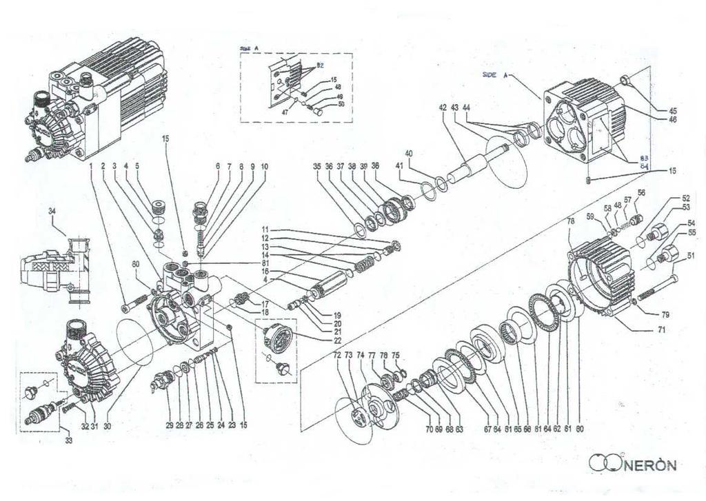
14 SPARE PARTS LIST item code description quantity Screw TCE A2 12x055 (torque 5/6 kg) Brass head Anodized alluminium manifold Outlet valve (HWB ) (torque 4 kg) Outlet valve (HWB 150) (torque 4 kg) O-R Sh Outlet valve plug (torque 4/5 kg) Outlet nipple M22 x M22x1.5 (torque 4/5 kg) Outlet nipple M22 x 3/8" F NPT (torque 4/5 kg) Outlet nipple M22 x 3/8" F BSP (torque 4/5 kg) Outlet nipple M22 x 1/2" F BSP (torque 4/5 kg) O-R 15,6x1,78-90 Sh Back relief valve spring Back relief hexagonal valve O-R 6x3-90 Sh Hexagonal nut M Screw STEI M16 x By pass regulation spring Spring spacer Ø Screw 906 8x1x8 conical Spring nipple (torque 4/5 kg) Inlet valve (torque 1,5/2 kg) O-R 18x2-90 Sh Back ring for O-R 7 x O-R 7x2-70 Sh By pass piston female Pressure rear connection gauge bar / 5700 psi (torque 2,5/3 kg) Pressure radial gauge bar / 5700 psi (torque 2,5/3 kg) Plug with washer (torque 2,5/3 kg) O-R ,69x1,78-70 Sh Back ring for O-R By pass piston male with spherical head O-R ,6x1,78-70 Sh By pass shutter O-R 19x2-70 Sh Brass thermal relief valve M22x1, Brass water by-pass to tank dia Port 3/8" BSP F Plastic elbow 90 dia 15 back to tank O-R ,87x2,62-70 Sh Anodized manifold cover plate 3/4"BSP M Brass suction cover 3/4" NPT F Brass suction cover 3/4" BSP F Screw TCE A2 5 x 025 (torque 2/3 kg) Chemical suction injector (ON REQUEST) Plug M12x1 (+ O-R 4x3 70 Sh ) (torque 2,5/3 kg) Water draining valve Neròn filter 3/4"FF 80m & hose barb 3/4"M Neròn 1 filter 3/4"MM 80m + sockets 3/4"FF & hose barb 3/4"M (on req Washer for high pressure seal Ø 25 (for HWB 150) Washer for high pressure seal Ø 21 (for HWB 200) Washer for high pressure seal Ø 18 (for HWB 250) Washer for high pressure seal Ø 15 (for HWB 300) Washer for high pressure seal Ø 14 (HWB 400) High pressure seals Ø 32x25.1x2 (for HWB 150) High pressure seals Ø 21 (for HWB 200) High pressure seals Ø 18 (for HWB 250) High pressure seals Ø 15 (for HWB 300) High pressure seals Ø 14 (HWB 400) Back ring Ø 32x25.1x2 (for HWB 150) Back ring Ø 28x21x2 (for HWB 200) Back ring Ø 26x18x2 (for HWB 250) Back ring Ø 25x15x2 (for HWB 300) Back ring Ø 25x13,5x2 (HWB 400) 14
15 item code description quantity O-R 32x1,5-75 Sh Brass water bushing Ø 25 (for HWB 150) Brass water bushing Ø 21 (for HWB 200) Brass water bushing Ø 18 (for HWB 250) Brass water bushing Ø 15 (for HWB 300) Boccola tenuta acqua Ø 13,7 ottone (HWB 400) Stainless steel washer Ø38 / Ø25.5 (for HWB 150) Stainless steel washer Ø38 / Ø21.5 (for HWB 200) Stainless steel washer Ø38 / Ø18.5 (for HWB 250) Stainless steel washer Ø38 / Ø15.5 (for HWB 300) Rondella Ø 14 inox (HWB 400) O-R Sh Complete piston Ø 25 (for HWB 150) Complete piston Ø 21 (for HWB 200) Complete piston Ø 18 (for HWB 250) Complete piston Ø 15 (for HWB 300) Complete piston Ø 13,5 (HWB 400) O-R 90x2-70 Sh Turcon-Glyde Ø Turcon-Glyde Ø Anodized aluminium body three-four fixing holes Brass body with three-four fixing holes O-R 5x3-90Sh Ball Ø Valve spring Valve plug Pressure switch device (upon request) Screw TCE A2 8 x 065 (torque 3/3,5 kg) O-R ,17x1,78 90 sh Oil inlet nipple 1/2" BSP Oil inlet nipple 1/2" BSP F (only for brass bottom) Oil inlet nipple 1/2" NPT F Gasket 1/2" BSP Oil outlet nipple 1/2" BSP Oil outlet nipple 1/2" NPT Ventil valve plug Ventil valve spring Ventil valve seat O-R 10 x 1,3-90 Sh Shim 68x55x0,1 (use as needed) Shim 68x55x0,2 (use as needed) Shim 68x55x0,3 (use as needed) Flat bearing AS Oil distribution KIT Niddle bearing Wobble plate Bearing th. 4mm Back ring 25x19,3x1, O-R 19 x 3-90 Sh Half ball spring Aluminium anodized bottom Culatta ottone Oil distributor O-R 87 x 2-70 Sh Swaying disc Piston retainer KIT Cylindrical pin Ø Washer C98 for screw Ø Washer for screw M Nozzle (HWB 250-HWB 300) 1 82 Fixing holes Aluminium revetted data plate (HWB 150) Aluminium revetted data plate (HWB 200) Aluminium revetted data plate (HWB 250) Aluminium revetted data plate (HWB 300) Aluminium revetted data plate (HWB 400) 15
16 16
GENERAL PUMPA member of the Interpump Group
 FEATURES Innovative drive design eliminates need for auxiliary hydraulic drive HWB Series Hydraulic Drive - Triplex Plunger Pump HWB2512 & HWB2112 Forged brass manifold No scheduled maintenance required
HWB Series GENERAL PUMP. Hydraulic Drive Triplex Plunger Pump INDUSTRIAL INDUSTRIAL FEATURES
 GENERAL PUMP HWB Series Hydraulic Drive Triplex Plunger Pump FEATURES INDUSTRIAL INDUSTRIAL Innovative drive design eliminates need for auxiliary hydraulic drive Forged brass manifold Built-in Pump Thermal
Electric Pressure Washer
 FEATURES This lightweight, portable high-pressure washer makes the toughest clean-up tasks faster and easier. Weighing only 43 pounds, you can take it virtually anywhere. Ideal for light industrial applications
OPERATING INSTRUCTIONS MODE D EMPLOI GEBRAUCHSANLEITUNG INSTRUCCIONES PARA EL USO CENTER 200
 OPERATING INSTRUCTIONS MODE D EMPLOI GEBRAUCHSANLEITUNG INSTRUCCIONES PARA EL USO CENTER 200 PULICAR - di D Annibale e C. S.n.c. 41058 - VIGNOLA (MO) - Via Puccini, 165 - Tel. 059.775061 - Fax 059.764045
WA 2719 ( 604 ) ( 604 ) , H.E.R.O.
 ( 604 ) , H.E.R.O.") a division of Middlefield Bancorp Limited 2719 Lake City Way, Burnaby, B.C., Canada Phone: ( 604 ) 420-6543 Fax: ( 604 ) 420-8725 Toll Free: 1-800-494-4376 E-mail: sales@hero.ca Website: www.hero.ca U.S.
a division of Middlefield Bancorp Limited 2719 Lake City Way, Burnaby, B.C., Canada Phone: ( 604 ) 420-6543 Fax: ( 604 ) 420-8725 Toll Free: 1-800-494-4376 E-mail: sales@hero.ca Website: www.hero.ca U.S.
Service Handbook HD /97
 Service Handbook HD 1050 5.905-032 07/97 Foreword HD 1050 Foreword Indispensable prerequisites for the competent execution of service procedures are comprehensive, real-life training workshops for technical
Table of Contents WARRANTY
 H.E.R.O. Industries a division of Middlefield Bancorp Limited 2719 Lake City Way, Burnaby, B.C., Canada Phone: ( 604 ) 420-6543 Fax: ( 604 ) 420-8725 Toll Free: 1-800-494-4376 E-mail: sales@hero.ca Website:
HOT WASHER MODEL NO: KING 125 OPERATION & MAINTENANCE INSTRUCTIONS PART NO: LS1009
 HOT WASHER MODEL NO: KING 125 PART NO: 7320170 OPERATION & MAINTENANCE INSTRUCTIONS LS1009 INTRODUCTION Thank you for purchasing this Hot Washer. This machine is a portable, high pressure power washer,
Table of Contents WARRANTY
 a division of Middlefield Bancorp Limited 2719 Lake City Way, Burnaby, B.C., Canada Phone: ( 604 ) 420-6543 Fax: ( 604 ) 420-8725 Toll Free: 1-800-494-4376 E-mail: sales@hero.ca Website: //www.hero.ca
SAFETY AND OPERATING MANUAL
 SAFETY AND OPERATING MANUAL COLD WATER PETROL WATER BLASTERS Read Safety & Operating Instructions Before Commencing Operation THESE INSTRUCTIONS MUST BE READ AND ADHERED TO BEFORE OPERATING THIS MACHINE.
A member of the Interpump Group
 FEATURES Nickel-plated cast manifold manufactured like heavy-duty pump line Triplex Plunger Pump, Gas New generation seal package New dust protection chamber TRIPLEX TRIPLEX Solid ceramic plungers New
Professional Series 1/2HP 2 YEAR WARRANTY CONVERTIBLE JET PUMP REPAIR PARTS
 Model T033 CONVERTIBLE JET PUMP /HP 900 GPH Suction lift Head of 5 (7.5m) in shallow well mode Professional Series YEAR WARRANTY Suction: /4 Discharge: NPT Maximum pressure: 85 PSI US GPH LPH 5 900 3400
TWO-STAGE HYDRAULIC PUMP. RWP55-IBT-Air
 ORIGINAL INSTRUCTIONS Form No.1000458 5 SPX Corporation 5885 11th Street Rockford, IL 61109-3699 USA Tech. Services: (800) 477-8326 Fax: (800) 765-8326 Order Entry: (800) 541-1418 Fax: (800) 288-7031 Internet
Model T Professional Series 1/2HP 2 YEAR WARRANTY SHALLOW WELL JET PUMP
 Model T03121 SHALLOW WELL JET PUMP Professional Series 2 YEAR WARRANTY 1/2HP 916 GPH Head of 25 (7,5 m) US GPH LPH Suction: 1 1/4 NPT Discharge: 1 NPT Maximum Pressure: 65 PSI Stainless steel shaft and
Complete orbital coverage of all interior surfaces. Suitable for use in the food industry. Model Number Y Y Rated Pressure
 FEATURES Designed for quick and efficient cleaning of interior surfaces of tanks and barrels. TANK CLEANING TANK CLEANING Note: Nozzles not included SPECIFICATIONS Model Number Y25479000 Y25479100 Rated
SERVICE MANUAL MODEL # ORDER # RG
 SERVICE MANUAL MODEL # ORDER # RG-232637 1.107-235.0 9.801-589.0 CONTENTS Exploded View... 4 Exploded View Parts List... 5 Legacy Axial Pump...6-7 Troubleshooting... 8 Preventive Manteinance... 9 Oil
1600 PSI ELECTRIC PRESSURE WASHER
 MODEL NO.: XE03 SKU: 39-8508-6 1600 PSI ELECTRIC PRESSURE WASHER Owner s Manual QUESTIONS, PROBLEMS, MISSING PARTS? Before returning to your retailer, visit our web site or call our customer service at
VB 10 - Unloader Valve (discharging)
") Last update: 20/04/18 VB 10 - Unloader Valve (discharging) Technical manual: E 212 Pressure regulating unloader valve with discharge control pressure with very low readings. At gun-lance closure, the water
Last update: 20/04/18 VB 10 - Unloader Valve (discharging) Technical manual: E 212 Pressure regulating unloader valve with discharge control pressure with very low readings. At gun-lance closure, the water
Model GP Triplex Ceramic Plunger Pump Operating Instructions/ Manual
 Model GP6145-3100 Triplex Ceramic Plunger Pump Operating Instructions/ Manual Contents: Installation Instructions: page 2 Pump Specifications: page 3 Exploded View: page 4 Parts List / Kits: page 5 Repair
Paint/Solvent/Dump Valve and Flow-Through Valve
 Instruction Sheet P/N 08573D Paint/Solvent/Dump Valve and Flow-Through Valve. Description See Figure. The paint/solvent/dump valve is a normally-closed valve that opens to trigger and/or dump coating material.
HWB HPP HPX HWD. Power being equal our pump is the smallest, the lightest and the most economical. in price worldwide!
 HWB HPP Power being equal our pump is the smallest, the lightest and the most economical in price worldwide! THE ULTIMATE COLD WATER HIGH PRESSURE SYSTEM HIGH PRESSURE HYDRAULICALLY DRIVEN PRESSURE WASHER
Triplex Plunger Pump, Total Start-Stop Feature
 GENERAL PUMP A member of the Interpump Group ET Series FEATURES Total start-stop feature allows flow to activate electric motor Built-in unloader Triplex Plunger Pump, TRIPLEX TRIPLEX Nickel-plated cast
Model LP200, LP250 & LP250W-MT
 Triplex Ceramic Plunger Pump Operating Instructions/ Repair and Service Manual Model LP200, LP250 & LP250W-MT Updated 5/02 Contents: Installation Instructions: page 2 LP200 Specifications: page 3 Exploded
model # Order # Xpert-HD 2.3/23 p / DD Xpert-HD 2.5/27 p / DD PD
 Service MANUAL model # Order # Xpert-HD 2.3/23 p / DD-232336 1.107-103.0 Xpert-HD 2.3/23 p / DD-232337 1.107-104.0 Xpert-HD 2.5/27 p / DD-252737 1.107-106.0 PD3-23326 1.107-091.0 PD3-23327 1.107-092.0
Model BP6150. Triplex Ceramic Plunger Pump Operating Instructions/ Manual
 Model BP6150 Triplex Ceramic Plunger Pump Operating Instructions/ Manual Contents: Installation Instructions: page 2 Pump Specs: page 3 Exploded View: page 4 Parts List / Kits Torque Specifications: page
MACH 1A HVLP (MACH 1AV HVLP) Automatic Airspray Gun
 Automatic Airspray Gun") MACH 1A HVLP (MACH 1AV HVLP) Automatic Airspray Gun Your new Binks MACH 1A HVLP Automatic Spray Gun is exceptionally rugged in construction, and is built to stand up under hard, continuous use. However,
MACH 1A HVLP (MACH 1AV HVLP) Automatic Airspray Gun Your new Binks MACH 1A HVLP Automatic Spray Gun is exceptionally rugged in construction, and is built to stand up under hard, continuous use. However,
DIAPHRAGM PUMPS: Instruction Manual
 INTRODUCTION DIAPHRAGM PUMPS: Instruction Manual Congratulations for choosing a product Imovilli Pompe, the result of a careful manufacturing process supported by over fifty years of specific experience
Models P420A-3100 & P420A-5100
 Models P420A-3100 & P420A-5100 Triplex Ceramic Plunger Pump Operating Instructions/ Repair and Service Manual Corrossion Resistant Pumps Contents: Installation Instructions: page 2 Specifications: page
DELUXE TELESCOPING LANCE ASSEMBLY
 DELUXE TELESCOPING LANCE ASSEMBLY Products Part # Lenght Inlet Outlet 27.0080 18 3/8 Plug 1/4" QC F 27.0082 24 3/8 Plug 1/4" QC F The product come supplied with: - Non Molded Extension Wand M22 Male Inlet
Models GP5132, GP5136, GP5142 & GP5145. Triplex Ceramic Plunger Pump Operating Instructions / Manual
 Models GP5132, GP5136, GP5142 & GP5145 Triplex Ceramic Plunger Pump Operating Instructions / Manual Updated 07/14 Contents: Installation Instructions: page 2 Pump Specifications: page 3 Exploded View:
P318, P321, P324, P327,
 P300 Series - 12 & 20 mm versions Triplex Ceramic Plunger Pump Operating Instructions/ Repair and Service Manual For Models: P314, P318, P321, P324, P327, and P330 Updated 11/17 Contents: Installation
SERVICE PARTS LIST SPECIFY CATALOG NO. AND SERIAL NO. WHEN ORDERING PARTS 13 HP DIRECT DRIVE PRESSURE WASHER CATALOG NO
 SPECIFY CATALOG NO. AND SERIAL NO. WHEN ORDERING PARTS HP DIRECT DRIVE PRESSURE WASHER CATALOG NO. 555-22 SERVICE PARTS LIST STARTING SERIAL NUMBER B06A REVISED BULLETIN PAGE OF BULLETIN NO. 5-20-000 DATE
TECHNICAL SPECIFICATIONS RATED PRESSURE MAX FLOW RATE. L/ min. USGpm bar MPa C F g lbs
 Last Update: 30/01/17 RB 65 Adjustable spray wash gun for food industry - 24 bar 2.4 MPa Technical manual : E 123 Guns suitable for use up to 24 bar 2.4 MPa rated pressure pumps. Shockproof gun with adjustable
Models GP7545GB-180/ GP7555GB-180. Gearbox Versions for Pinion Shaft Drives
 Models GP7545GB-180/ Triplex Ceramic Plunger Pump Operating Instructions/ Repair and Service Manual GP7555GB-180 Gearbox Versions for Pinion Shaft Drives Contents: Installation Instructions: page 2 Pump
FRP SystemOne GELCOATER OPERATION MANUAL. MAGNUM VENUS PRODUCTS Operation Manual. Part No. M Revision
 1300-1-1 GELCOATER OPERATION MANUAL MAGNUM VENUS PRODUCTS Operation Manual Part No. M1300-1-1 Revision 04.26.01 Operation Manual Unit Information Unit # Type Of: Power Cylinder Metering Pump Gun Fluid
DIRECT-DRIVE PRESSURE WASHERS
 DIRECT-DRIVE PRESSURE WASHERS PJG SERIES PRESSURE WASHER MANUFACTURED BY: PJG-2002B PJG-2502-6.5B PJG-3002B PJG-4002B INTRODUCTION Thank you for purchasing a Mancorp Pressure Washer. This manual covers
P SERIES PUMPS. 18mm Versions Nickle-Aluminum Bronze Models: P , P , P , P , P , P , P
 P200-3100 SERIES PUMPS 18mm Versions Nickle-Aluminum Bronze Models: P217-3100, P218-3100, P219-3100, P220-3100, P221-3100, P227-3100, P230-3100 Triplex Ceramic Plunger Pump Operating Instructions/ Repair
Plunger Pumps. Plunger Pumps LIMITED WARRANTY
 Torque Specifications in/lbs:(ft/lbs) Oil Manifold Piston Rear Side Valve Connecting Capacity (Head) Nut Cover Cover Cap Rods 92/(5) N/A 71/(6) N/A 442/(7) N/A LIMITED WARRANTY Annovi Reverberi (A.R.)
INSTALLATION INSTRUCTIONS
 www.burcam.com 2190 Dagenais Blvd.West TEL: 514.337.4415 LAVAL (QUEBEC) FAX: 514.337.4029 CANADA H7L 5X9 info@burcam.com INSTALLATION INSTRUCTIONS MODEL 506518SS AND BY-PRODUCTS LIKE Your pump has been
MK Rittenhouse & Sons Ltd. 115 Litre/30 US Gallon Greenhouse Sprayer Manual
 MK Rittenhouse & Sons Ltd. 115 Litre/30 US Gallon Greenhouse Sprayer Manual TABLE OF CONTENTS Introduction 3 Precautions & Maintenance 4-5 Piston pump Care & Maintenance 5-6 Shut Down & Winterizing 6 Troubleshooting
5020 Series Injector
 5.2018.9.k 1 5020 Series Injector 1 2 3 4 5 6 10 11 7 12 13 8 2 14 Parts List 15 16 17 Item # Part # # Reqd. Description Material Alternate Part # 1 A-1854 1 0-12 PSI Pressure Gauge A-1295SS 2 A-0022 1
IMPORTANT OPERATING CONDITIONS. Failure to comply with any of these conditions invalidates the warranty. STANDARD CONFIGURATIONS
 X-SERIES TRIPLEX CERAMIC PLUNGER PUMPS OPERATING MANUAL MODELS X8 X10 X20 IMPORTANT OPERATING CONDITIONS Failure to comply with any of these conditions invalidates the warranty. Lubrication - Prior to
IBT Series Square Drive Torque Wrenches
 IBT Series Square Drive Torque Wrenches Operation and Maintenance Manual Model.75, 1, 3, 5, 8, 10, 20, 25, 35, 50 http://www.torsionx.com Use the IBT Series Square Drive Torque Wrenches Model.75, 1, 3,
DEMA MODEL 693T FOAM STATION II INSTALLATION INSTRUCTION
 1. PARTS CHECKLIST: 2. INSTALLATION: DEMA MODEL 93T FOAM STATION II ITEM DESCRIPTION QTY. A. Foam Station Assembly 1 B. ¼ ID Tubing & Foot Strainer 1 C. 3/ ID Tubing & Foot Strainer 1 D. Ceramic Weight
Material required for drilled well application (indoor use only)
") SAFETY INSTRUCTIONS: This fine pump that you have just purchased is designed from the latest in material and workmanship. Before installation and operation, we recommend the following procedures: A B C
SAFETY INSTRUCTIONS: This fine pump that you have just purchased is designed from the latest in material and workmanship. Before installation and operation, we recommend the following procedures: A B C
USE and MAINTENANCE INSTRUCTION MANUAL AZ3 HTE2 AZ3 HTE2 HVLP GRAVITY. SPRAY GUN Series. en it fr es pt de se
 USE and MAINTENANCE INSTRUCTION MANUAL AZ3 HTE2 AZ3 HTE2 HVLP GRAVITY SPRAY GUN Series en it fr es pt de se TECHNICAL DATA Technical AZ3 HTE2 AZ3 HTE2 HVLP 1.0 80 180 1.3 10-15HTE 140 200 240 1.5 2.0 160
AIR COMPRESSOR OPERATING INSTRUCTION AND PARTS LIST
 AIR COMPRESSOR OPERATING INSTRUCTION AND PARTS LIST BELT TYPE IMPORTANT PLEASE MAKE CERTAIN THAT THE PERSON WHO IS TO USE THIS EQUIPMENT CAREFULLY READS AND UNDERSTANDS THESE INSTRUCTIONS BEFORE STARTING
SERVICE MANUAL MODEL # ORDER # XPERT-HD 3.8/35 P PD DA DD
 SERVICE MANUAL MODEL # ORDER # XPERT-HD 3.8/35 P 1.107-108.0 PD4-35324 1.107-096.0 DA-383539 1.107-102.0 DD-383537 1.107-137.0 8.780-001.0 CONTENTS Exploded View... 4 Exploded View Parts List... 5 S.2
180 Lake Ave North Paynesville, MN Phone: (320) MASTER MANUFACTURING MASTER GARDNER
 MASTER MANUFACTURING MASTER GARDNER") 180 Lake Ave North Paynesville, MN 56362 Phone: (320) 340-6464 www.master-mfg.com MASTER MANUFACTURING MASTER GARDNER Part Number PCD-E3-009B-MM July 2017 Note: Do not return product to the distributor/dealer
180 Lake Ave North Paynesville, MN 56362 Phone: (320) 340-6464 www.master-mfg.com MASTER MANUFACTURING MASTER GARDNER Part Number PCD-E3-009B-MM July 2017 Note: Do not return product to the distributor/dealer
P300 Series - 16 & 18 mm versions. Triplex Ceramic Plunger Pump Operating Instructions/ Repair and Service Manual
 P300 Series - 16 & 18 mm versions Triplex Ceramic Plunger Pump Operating Instructions/ Repair and Service Manual For Models: P316, P317, P319, P322, P323, P325 & P340 Updated 06/13 Contents: Installation
MODEL SS INSTALLATION INSTRUCTIONS
 WWW.BURCAM.COM 2190 Boul. Dagenais West TEL: 514.337.4415 LAVAL (QUEBEC) FAX: 514.337.4029 CANADA H7L 5X9 info@burcam.com Your pump has been carefully packaged at the factory to prevent damage during shipping.
Section 10 Chapter 17
 Section 10 Chapter 17 24 Valve, 8.3 Liter Engine Air Intake System Note: All coding used in the 8.3 Liter and 9 Liter engine manuals are Cummins engine codes. These engine codes have no meaning to New
P300 Series - 16 & 18 mm versions. Triplex Ceramic Plunger Pump Operating Instructions/ Repair and Service Manual
 P300 Series - 16 & 18 mm versions Triplex Ceramic Plunger Pump Operating Instructions/ Repair and Service Manual For Models:P316, P317, P319, P322, P323, P325, P328, P329, P332 & P340 Updated 03/16 Contents:
Model GX Series. Consumer Pump. Triplex Plunger Pump Operating Instructions/ Repair Instructions Manual
 Model GX Series Triplex Plunger Pump Operating Instructions/ Repair Instructions Manual Consumer Pump Horizontal/Vertical Pump with built-in Thermal Relief Valve and Siphon Injector Contents: Installation
OWNER S MANUAL. ROTARY SURFACE CLEANER Models 105C, 105F, 105CW, & 105FW. Revision 2.01
 OWNER S MANUAL ROTARY SURFACE CLEANER Models 105C, 105F, 105CW, & 105FW Revision 2.01 ROTARY SURFACE CLEANER WARNING HIGH PRESSURE CAN CAUSE SERIOUS INJURY, MAXIMUM WORKING PRESSURE IS 4000 P.S.I. Any
Heavy Duty Sprayer Owners Manual Model MS-O
 Heavy Duty Sprayer Owners Manual Model MS-O Table of Contents Warranty 4 Warning 5 Assembly and Preparation 6 Operation 7 Cleaning and Storage 7 Standard Spray Gun & Parts List 8 Trigger Style Spray Gun
INSTALLATION INSTRUCTIONS
 www.burcam.com 2190 Dagenais Blvd.West TEL: 514.337.4415 LAVAL (QUEBEC) FAX: 514.337.4029 CANADA H7L 5X9 info@burcam.com Your pump has been carefully packaged at the factory to prevent damage during shipping.
AIRCLEAN 32 USER MANUAL. High-pressure cleaner. Wilhelmsen Ships Service. Produced in Norway for:
 AIRCLEAN 32 High-pressure cleaner USER MANUAL Produced in Norway for: Wilhelmsen Ships Service Contents E.1 IMPORTANT INFORMATION 3 E.1.1 Safety 3 E.1.2 Lubrication 3 E.1.3 Air operating pressure 3 E.1.4
AMB100L-im-issue INSTRUCTION MANUAL 240V DIESEL MINI BOWSER AMB100L AMB100L
 -im-issue1-2015 INSTRUCTION MANUAL 240V DIESEL MINI BOWSER INSTRUCTION MANUAL 240V DIESEL MINI BOWSER INTRODUCTION Thank you for purchasing a Macnaught 240V Diesel Mini Bowser (100 l/min) The Macnaught
Model GXR Series. Consumer Pump. Triplex Plunger Pump Operating Instructions/ Repair Instructions Manual
 Model GXR Series Triplex Plunger Pump Operating Instructions/ Repair Instructions Manual Consumer Pump Horizontal/Vertical Pump with built-in Regulator, Thermal Relief Valve and Siphon Injector MADE IN
OPERATION AND MAINTENANCE MANUAL
 WREN IBT SERIES HYDRAULIC TORQUE WRENCHES IBT SQUARE DRIVE SERIES OPERATION AND MAINTENANCE MANUAL FOR WREN Products: POINT 75, 1IBT, 3IBT, 5IBT, 8IBT, 10IBT, 20IBT, 25IBT, 35IBT, 50IBT SQUARE DRIVE HYDRAULIC
Model GP5128. Triplex Ceramic Plunger Pump Operating Instructions / Manual
 Model GP5128 Triplex Ceramic Plunger Pump Operating Instructions / Manual Updated 11/17 Contents: Installation Instructions: page 2 Pump Specifications: page 3 Exploded View: page 4 Parts List: page 5
Operating instructions Form no safety definitions
 Operating instructions Form no. 1000437 safety definitions safety symbols are used to identify any action or lack of action that can cause personal injury. Your reading and understanding of these safety
Steam/Water Washdown Units Safety and Operation Installation and Maintenance Instructions
 INSTALLATION AND MAINTENANCE INSTRUCTIONS IM-8-002-US October 2016 Steam/Water Washdown Units Safety and Operation Installation and Maintenance Instructions These instructions should be read by the Company
Model GXR Series. Consumer Pump. Triplex Plunger Pump Operating Instructions/ Repair Instructions Manual
 Model GXR Series Triplex Plunger Pump Operating Instructions/ Repair Instructions Manual Consumer Pump Horizontal/Vertical Pump with built-in Regulator, Thermal Relief Valve and Siphon Injector Updated
HPD Hydraulic Post Driver
 HPD Hydraulic Post Driver From serial No. 7600 Revised 04.01.2013 Prior to Operation We thank you for choosing a HYCON Post Driver. To ensure smooth operation and long-lasting performance of your new post
Model GP5128HS. Hydraulic Drive Pump. Triplex Ceramic Plunger Pump Operating Instructions / Manual
 Model GP5128HS Hydraulic Drive Pump Triplex Ceramic Plunger Pump Operating Instructions / Manual Contents: Installation Instructions: page 2 Pump Specifications: page 3 Exploded View: page 4 Parts List:
Super T QR20 INSTRUCTIONS GENERAL RULES
 INSTRUCTIONS GENERAL RULES 1. Where specified, assemble and disassemble the shock absorption system using the MARZOCCHI special tools only. 2. On reassembling the suspension system, always use new seals.
PETROL POWER WASHER MODEL NO: PLS195, PLS265 OPERATION & MAINTENANCE INSTRUCTIONS PART NO: , LS0616
 PETROL POWER WASHER MODEL NO: PLS195, PLS265 PART NO: 7330360, 7330365 OPERATION & MAINTENANCE INSTRUCTIONS LS0616 INTRODUCTION Thank you for purchasing this CLARKE Petrol Power Washer. Before attempting
 Operation and Maintenance Manual http://www.torsionx.eu Use the MaxDrv Series Square Drive Torque Wrench Model.75, 1, 3, 5, 8, 10, 20, 25, 35, 50 to install and remove threaded fasteners requiring precise
Plunger Pumps. RSV Series Pumps NORTH AMERICA. Description. Operating Instructions and Parts Manual
 Please read and save these instructions. Read carefully before attempting to assemble, install, operate or maintain the product described. Protect yourself and others by observing all safety information.
Pump Operating and Maintenance Manual - Models
 Pump Operating and Maintenance Manual - Models 78-00111 - 78-0057 Thank you for purchasing the SDI Diaphragm Pump manufactured by Comet Pump. Comet produces quality products which are safe, efficient and
VB Unloader Valve (discharging)
") Last update: 07/07/10 VB 135 - Unloader Valve (discharging) Pressure regulating unloader valve complete with metallic intake manifold. At gun shut off, the water flow is bypassed at reduced pressure. Technical
Last update: 07/07/10 VB 135 - Unloader Valve (discharging) Pressure regulating unloader valve complete with metallic intake manifold. At gun shut off, the water flow is bypassed at reduced pressure. Technical
Model GXR Series. Consumer Pump. Triplex Plunger Pump Operating Instructions/ Repair Instructions Manual
 Model GXR Series Triplex Plunger Pump Operating Instructions/ Repair Instructions Manual Consumer Pump Horizontal/Vertical Pump with built-in Regulator, Thermal Relief Valve and Siphon Injector Updated
DEMA MODEL 692T FOAM STATION I INSTALLATION INSTRUCTION
 1. PARTS CHECKLIST: ITEM DESCRIPTION QTY. A. Foam Station Assembly 1 B. #10 Screw & Anchor Kit Set (Total: 4 Screws & 4 Anchors) 1 C. Ceramic Weight 1 D. ¼ ID Tubing & Foot Valve Assembly 1 E. Metering
Page 1 of 19. Part# /10/2006
 Part# 1002733-01 10/10/2006 This manual contains important information concerning the installation and operation of the gun washers listed above. Read manual thoroughly and keep for future reference INSTRUCTIONS
POMPE AUTOADESCANTI SELF-PRIMING ELECTRO PUMP ACM DISASSEMBLY AND ASSEMBLY INSTRUCTIONS FOR MULTISTAGE SELF-PRIMING PUMPS
 POMPE AUTOADESCANTI SELF-PRIMING ELECTRO PUMP ACM DISASSEMBLY AND ASSEMBLY INSTRUCTIONS FOR MULTISTAGE SELF-PRIMING PUMPS Ed. 02/2011 5 WARNING These instructions are for the maintenance personnel for
INSTALLATION INSTRUCTIONS MODELS S S S S SSN S SSW SSN SPRINKLER PUMPS
 WWW.BURCAM.COM 2190 Boul. Dagenais West TEL: 514.337.4415 LAVAL (QUEBEC) FAX: 514.337.4029 CANADA H7L 5X9 info@burcam.com Your pump has been carefully packaged at the factory to prevent damage during shipping.
WORKSHOP MANUAL. Chainsaw GS35 GS350 MT350 MT3500
 WORKSHOP MANUAL Chainsaw GS35 GS350 MT350 MT3500 General failures analysis Suggested tools I. Emak tool kit II. Compression tester: to check thermal group III. Electronic tachometer: for 2 and 4 stroke
Service Handbook. High-Pressure Washer Pump
 Pump 629 9/28/01 3:22 PM Page 1 Service Handbook High-Pressure Washer Pump 3.532-629.0 10.00 Pump 629 9/28/01 3:22 PM Page 2 Pump 629 9/28/01 3:22 PM Page 3 TROUBLESHOOTING OVERVIEW How to Use This Manual
INSTRUCTIONS. Fc. -1,<" SERIES ST-261 REGULATING UNLOADER VALVE
 INSTRUCTIONS Fc. -1,
Agxcel GX12i Chemical Injection System
 Agxcel GX12i Chemical Injection System Table of Contents System Contents... 3 Specifications... 4 Safety Precautions and Tips... 5 Operations... 6 Installation... 7 Maintenance... 8-9 Troubleshooting...
 Operation and Maintenance Manual Model.75,, 3, 5, 8, 0, 0, 5, 35, 50 http://www.torsionx.com Use the MaxDrv Series Square Drive Torque Wrench Model.75,, 3, 5, 8, 0, 0, 5, 35, 50 to install and remove threaded
HUGH CRANE. SOUTH WALSHAM ROAD, ACLE, NORWICH, NORFOLK, NR13 3ES TEL: FAX:
 HUGH CRANE Cleaning Equipment Limited SOUTH WALSHAM ROAD, ACLE, NORWICH, NORFOLK, NR13 3ES TEL: 01493 750072 - FAX: 01493 751854 - www.hughcrane.co.uk FS0962 OPERATOR INSTRUCTION MANUAL COMMANDO 500P For
Pump Model P Corrosion Resistant Pump
 Pump Model P450-5100 Corrosion Resistant Pump Triplex Ceramic Plunger Pump Operating Instructions Repair and Service Manual 07/09 Contents: Installation Instructions: page 2 Specifications: page 3 Exploded
Models GP7645GB-180/ GP7655GB-180. Gearbox Versions for Pinion Shaft Drives
 Models GP7645GB-180/ Triplex Ceramic Plunger Pump Operating Instructions/ Repair and Service Manual GP7655GB-180 Gearbox Versions for Pinion Shaft Drives Contents: Installation Instructions: page 2 Pump
INSTALLATION INSTRUCTIONS MODELS S S SHALLOW WELL & CONVERTIBLE JET PUMPS PAGE 3 PAGE 8
 INSTALLATION INSTRUCTIONS WWW.BURCAM.COM 2190 Blvd. Dagenais West LAVAL (QUEBEC) CANADA H7L 5X9 MODELS 503132S 503332 503232S 503732 TEL : 514.337.4415 FAX : 514.337.4029 info@burcam.com Your pump has
AIRMIX PUMP and LOW-PRESSURE PUMP air motor with reversing block
 INSTRUCTION MANUAL AIRMIX PUMP and LOW-PRESSURE PUMP air motor with reversing block Manual : 0306 573.002.212 Date : 12/06/03 Supersedes : 17/06/02 Modif. 1 + 4 added KREMLIN REXSON Site de Stains : 150,
DIRECT-DRIVE PRESSURE WASHERS
 DIRECT-DRIVE PRESSURE WASHERS PJG SERIES PRESSURE WASHER MANUFACTURED BY: PJG-2001 PJG-2501-6.5 PJG-2501 PJG-3000 PJG-3001 PJG-3501 PJG-4001 OPERATOR s INTRODUCTION Thank you for purchasing a Mancorp Pressure
Series CP200. Triplex Ceramic Plunger Pump Operating Instructions/ Repair and Service Manual. For Models: CP218 CP219 CP220 CP230
 Series CP200 Triplex Ceramic Plunger Pump Operating Instructions/ Repair and Service Manual For Models: CP218 CP219 CP220 CP230 Updated 10/02 Contents: Installation Instructions: page 2 Pump Specifications:
TS Series. MultiStage Centrifugal Pump Instruction Manual. Walrus America Inc. ISO 9001 Certified
 TS Series MultiStage Centrifugal Pump Instruction Manual 234867 ISO 9001 Certified Walrus America Inc EC Declaration of Conformity Manufacturer: Walrus Pump Co., Ltd. Address: No. 83-14, Dapiantou, Sanjhih
HYDROSTATIC TEST SYSTEM MANUAL
 PDQC HYDROSTATIC TEST SYSTEM MANUAL Technical Specification Operating Instructions Part List Revised 12-2016 Manual # PDQC- 6,000 And PDQC-10,000 1 PDQC PERFORMANCE DATA Model Number Maximum Pressure Volume
Ph: (07) Fax: (07) Pump Manual
 Fax: (07) Pump Manual") sales@scintex.com.au www.scintex.com.au Ph: (07) 3137 0135 Fax: (07) 3041 0541 Pump Manual 12V 75LPM Vane Pump & Vane Pump Station SPEP12V75 & SP12VFS75 SPEP12V75 SP12VFS75 Parts List No. Part Name QTY
sales@scintex.com.au www.scintex.com.au Ph: (07) 3137 0135 Fax: (07) 3041 0541 Pump Manual 12V 75LPM Vane Pump & Vane Pump Station SPEP12V75 & SP12VFS75 SPEP12V75 SP12VFS75 Parts List No. Part Name QTY
Air Actuated Hydraulic Bottle Jacks
 Air Actuated Hydraulic Bottle Jacks Operating Instructions & Parts Manual Model Number Atd-7412 Atd-7420 Capacity 12 Ton 20 Ton Atd Tools Inc. 160 Enterprise Drive, Wentzville MO 63385 Printed in China
INSTALLATION, OPERATING AND SERVICE MANUAL
 INSTALLATION, OPERATING AND SERVICE MANUAL ECONO-mist WATER SOFTENER Demand Regeneration 7-LMC56-75B 7-LM56-75B 7-LM56-100B 7-LM56-150B 7-LM56-200B Congratulations on purchasing your new Lancaster Water
Installation & Operator s Manual
 Installation & Operator s Manual LS6 Liquid Spray System for SHPE1500, 2000 Style Spreaders Installation Instructions 1. Position Support (3013939) in truck s bed. Place 30 gal. Tank (#3014062) on support
DP-139 PUMP DIMENSIONS
 3/2019 Table of Contents NOTES TO THE OWNER... 3 SELECTION OF PUMP AND EQUIPMENT DESIGN... 3 SAFETY PRECAUTIONS... 3 WARNING... 4 INSTALLATION SCHEME... 5 ORDINARY MAINTENANCE FOR DIAPHRAGM PUMPS... 6-7
Model CP420/CP425. Triplex Ceramic Plunger Pump Operating Instructions/ Repair and Service Manual
 Model CP420/CP425 Triplex Ceramic Plunger Pump Operating Instructions/ Repair and Service Manual Updated 02/12 Contents: Installation Instructions: page 2 Pump Specifications: page 3 Exploded View: page
SERVICE MANUAL
 SERVICE MANUAL MODEL # ORDER # HD 3.0/27 G 1.107-270.0 HD3.0/27 GB 1.107-271.0 HD 3.4/35 G 1.107-272.0 HD 3.3/35 GB HD 4.0/40 G HD 4.0/40 GB HD 4.0/40 Ge HD 4.0/40 GeB 1.107-273.0 1.107-274.0 1.107-275.0
Wash Prep Systems featuring CAT PUMPS DUPM623 DUPM820 / DUPM820-TS DUPM820D / DUPM820D-TS DUPM1010. Owner s Manual #
 Wash Prep Systems featuring CAT PUMPS DUPM623 DUPM820 / DUPM820-TS DUPM820D / DUPM820D-TS DUPM1010 Serial Number: Owner s Manual #0779 072415 Installation Date: Please read and understand this manual.