Spray Wyng II. Operator s & Parts Manual R4 Printed In The USA Specifications & Design Subject To Change Without Notice
|
|
|
- Alfred Pope
- 5 years ago
- Views:
Transcription


1 Spray Wyng II Operator s & Parts Manual R4 Printed In The USA Specifications & Design Subject To Change Without Notice
2 Warranty Information A Message To The Owner And Operator This equipment was carefully designed and manufactured to give you dependable service. To insure efficient operation of this equipment, please read this operator s manual carefully. Check each item and acquaint yourself with the adjustments required to maintain optimum performance and operation. Remember, this equipment s performance depends on how you operate and care for it! At the end of each season, thoroughly clean and inspect your equipment. Preventive maintenance saves time and pays dividends. Your nearest Wylie Spray Center has original equipment parts which assure proper fit and best performance. Record your equipment s model and serial numbers and the date you purchased this equipment in the space below. Have this information available when you order parts or attachments. Model Number: Serial Number: Date Purchased: Limited Warranty This is a limited warranty. It covers products manufactured by WYLIE Mfg. Co. The Warrantor is WYLIE Mfg. Co., 702 E. 40th St., Lubbock, TX USA. The duration of the warranty for WYLIE manufactured equipment and products (excluding polyethylene tanks) is for one year from date of delivery to the carrier. The Warrantor warrants to the Buyer that the product(s) sold hereunder are free from defects to material and workmanship, under normal use and service, in the hands of the original buyer. If goods are defective, the defective goods will be replaced with identical goods. If identical goods are not available, the Buyer may elect to receive a refund of the purchase price for the defective goods, or the Buyer may order similar goods. The damage for defective goods shall not exceed the purchase price of the defective goods. No allowance shall be made for labor or expense or repairing goods without prior approval in writing by the Warrantor. The Buyer s remedy under this warranty does not include incidental or consequential damages. For products not manufactured by the Warrantor, the Warrantor warrants these products to the extent of the warranties of their respective manufactures. There are no warranties which extend beyond this limited warranty, including the implied warranty of merchantability. Dealers or representatives shall not make any representation in regard to particular goods except as authorized by the Warrantor through a written warranty accompanying those particular goods. Disclaimer of Warranty WYLIE Mfg. Co., and its divisions, Wylie Spray Centers, in each location, requires as a condition of sale and coverage by its LIMITED WARRANTY that all equipment sold by it be used in accordance with the instructions and specifications of the Warrantor. This requirement is in addition to the LIMITED WARRANTY. Polyethylene and fiberglass tanks These tanks are warranted for the storage and transport of water, herbicide solutions (on farm), liquid fertilizer and liquid feed. Such tanks should not be used for the storage of any bulk herbicide (undiluted). Any such use will render this warranty void. In addition, the Warrantor makes no warranty with regard to bulkhead tank fittings used in connection with tanks containing bulk herbicides and the use of any such fittings sold by the Warrantor or any WYLIE dealer in connection with tanks containing bulk herbicides is improper. Chemical Incompatibility The Warrantor does not make any recommendations or warranties regarding chemical compatibility. WYLIE shall not be liable for any damages due to chemical incompatibility, and any Buyer or user should rely solely on written information furnished by the chemical manufacturer regarding chemical compatibility. No employee of WYLIE Mfg. Co., or its representatives, agents or dealers, is authorized to vary the terms of this limited warranty.

3 Owner Registration Wylie Manufacturing Company 702 E. 40th St. Lubbock, TX Ph Spray Wyng II Sprayer Date of Purchase Model Number Use of Applicator: Tank Serial Number Trailer Serial Number Boom Serial Number Pump Model Wylie Invoice Number Owner s Name Address Row Crop Small Grain Other Cotton Pasture City State Zip Phone Dealer Owner s Signature Must be returned within 10 days to validate the warranty. -- Or Register Online -- Go to:
4 .
5 Table of Contents Table Of Contents Safety Issues Safety Decals & Placement Introduction... 8 Inspection & Setup Boom Operation Sprayer Operation Maintenance Boom Adjustment Trailer Adjustment Lubrication Troubleshooting Guidelines Repair Parts Spray Wyng II Center Section...34 Spray Wyng II Suspension Spray Wyng II Primary Section...36 Spray Wyng II Boom Plumbing...36 Spray Wyng II Secondary Section...37 Spray Wyng II Breakaway Section...38 Spray Wyng II Hi-Lift Linkage...39 Spray Wyng II Control System...40 Spray Wyng II Hydraulic Hose Routing...41 W1510 VersaTrail Trailer W ,600 Gal. Spray Trailer...43 SW-1000-SA 1,000 Gal. Single Axle Trailer...44 SW-1000-ST 1,000 Gal. Tandem Axle Trailer...45 W1515 VersaTrakr Trailer (through 2018)...46 VersaTrakr Articulated Hydraulic System...47 VersaTrakr/VersaTrail Wheels and Axle...48 VersaTrakr, VersaTrail Pump Kit Pump Kit VersaTrakr, VersaTrail, 1600 Tank Plumbing...51 VersaTrakr, VersaTrail, 1600 Trailer Plumbing ,000 Tandem/Single Axle Trailer Plumbing Handler Mix Assembly/1600 Agitator Assembly Hydraulic System Raven Boom Valves Ace 304 Pump Ace 206 Pump
6 Safety Issues Safety Precautions Be alert when you see the above symbol in the manual. It warns of a hazard which might lead to injury. It means: Attention! Become alert! Your safety is Involved! Three (3) words (Danger, Warning, and Caution) are associated with this symbol. DANGER Indicates a hazardous situation, which, if not avoided, will result in death or serious injury. This signal word is to be limited to the most extreme situations. WARNING Indicates a hazardous situation, which, if not avoided, could result in death or serious injury. CAUTION Indicates a hazardous situation, which, if not avoided, may result in minor or moderate injury. NOTICE Indicates information considered important, but not hazard-related (e.g., messages relating to property damage). SAFETY INSTRUCTIONS - Indicates a type of safety sign where specific safety-related instructions or procedures are described. Before Use Do not operate sprayer until this manual has been read and understood! * Thoroughly read and understand all instructions before operating this sprayer. If you have questions, please contact Wylie Manufacturing, 702 E. 40th St., Lubbock, TX 79404, (888) You can also contact your nearest Wylie Spray Center. * Place an emblem on the rear of the unit prior to driving on open roads. * Always wear safety goggles, chemical resistant apron and rubber gloves when handling chemicals. * Read and understand the chemical manufacturer s safety guidelines on handling, mixing and application. During Use * Do not allow anyone to ride on sprayer during operation. Falling can cause injury. * Reduce speed when crossing uneven or rough terrain. * Always support the sprayer on parking stands and turn off tractor engine before making adjustments or repairs. 2
7 Safety Issues After Use * Inspect sprayer for wear or damage. * Ensure that all fasteners and fittings are tight. * Flush tank and pump with fresh water. Dispose of flush water using appropriate means. * Carry out maintenance and/or lubrication procedures as outlined in this manual. Always * Keep hands, feet and clothing away from moving parts. * Wear protective clothing and gloves when working with the hydraulic system. * Escaping hydraulic fluid under pressure can penetrate skin causing serious injury: Do Not use hands to check for leaks in hydraulic system, use cardboard or paper. Stop tractor engine and relieve pressure before connecting or disconnecting lines. Tighten all connections prior to starting engine or pressurizing line. If any fluid is injected into the skin, obtain medical treatment immediately to avoid gangrene. Operator s Instructions * Securely fasten seat belt if tractor is equipped with a (ROPS). * When possible, avoid operating the tractor near ditches, embankments and holes. * Reduce speed when turning, crossing slopes and on rough, slick or muddy surfaces. * Be aware of where you are going at all times; especially at row ends, roads and around trees. * Do not permit others to ride. * Operate tractor smoothly no jerky turns, starts and stops. * Hitch only to the drawbar and hitch points recommended by the tractor manufacturer. * When tractor is idle, engage brakes and park lock securely. * Tighten lug bolts before transporting and after the first five miles. * Limit transport speed to 25 mph. 3


8 Safety Issues Safety Decals & Placement VersaTrail/1600 Spray Trailer Decal #T2W Decal #V9003 Decal #V9044 Decal #SW701W Decal #V9043 Decal #SW700 Decal #V9055 Contact us at or to order safety decal or manual replacements. 4


9 Safety Issues Safety Decals & Placement VersaTrail/1600 Spray Trailer Decal #V9044 Decal #V9032 Decal #V9033 Decal #V9008 Decal #V9007 Decal #V9010 Contact us at or to order safety decal or manual replacements. 5

10 Safety Issues Safety Decals & Placement 1,000 Gal. Single/Tandem Axle Decal #SW700 Decal #V9055 Decal #SW701W Decal #T2W Contact us at or to order safety decal or manual replacements. 6


11 Safety Issues Safety Decals & Placement Spray Wyng II Boom Decal #V9045 Contact us at or to order safety decal or manual replacements. Decal #SW202 Decal #V9006 7

12 Introduction Introduction The Wylie Spray Wyng II Sprayer is built of the finest materials and expert workmanship to provide you with years of reliable service. The Spray Wyng II is built in five sizes, 60, 80, 90, 100 and 108 for trailer mounted configurations. All sizes are available for the VersaTrail and 1600 models. The 1,000 gallon models carries the 60 boom. This manual explains where and how to make necessary adjustments to your sprayer for safe and proper operation. Thoroughly read and understand the contents of this manual before operating your sprayer. If you have questions or do not understand particular items, contact your nearest Wylie Spray Center or call Wylie Manufacturing at (888) Please keep this manual handy to answer questions you may have as they arise. Pay Particular Attention To All Safety Suggestions Their purpose is to assure safe operation of the sprayer and prevent injury or damage to yourself or the sprayer. Note: In all references to the boom and trailer, left and right are determined by standing behind the sprayer and looking toward the tractor. 8


13 Inspection & Setup Spray Trailers The Spray Wyng II boom can be mounted on a variety of trailers including the VersaTrail, 1,600 gallon, the 1,000 gallon tandem axle, the 1,000 gallon single axle. The VersaTrail, 1,600 and 1,000 gallon tandem/single axle are delivered set up and should need no further assembly. The sprayer was tested at the factory, but the sprayer should be checked for any damage during shipment. It is important to check the lug bolts upon delivery and after 100 hours of operation. Tighten as necessary. Inspection & Setup All Spray Trailers: The Spray Wyng II Boom requires only two tractor remote circuits. One circuit powers the pump and while the other circuit powers all the boom functions. The Spray Wyng II, from the factory, is set up to operate on open-center and closed-center hydraulic systems without any modifications. Enhanced performance is available on closed-center systems with a field modification. Call Wylie Customer Service for details. ( ). < Electrical Connection < Pump Hyd. Hoses Figure A1 Check and Tighten Lug Bolts Attach the trailer tongue to the tractor drawbar. The sprayer should be leveled by adjusting the hitch in the trailer tongue. Lower the jack, unpin the hitch from the tongue and raise or lower the tongue as needed to level the sprayer. Pin the hitch in the appropriate holes. Hitch Pins Spray > Control Cable Lift/Tilt/Fold > Control Cable Figure A3 Hydraulic Hoses < Lift/Tilt/Fold Hyd. Hoses Transport Lights The Spray Wyng II is equipped with red and amber transport lights that function in the same way as the tractor s flashing lights. Make sure the sprayers lights are plugged in and operating before transporting the sprayer on any public road. Figure A2 Adjust Hitch To Level Sprayer Figure A4 Transport Lights 9


14 Inspection & Setup Installing Boom Controller The Spray Wyng II is equipped with an integrated boom control that mounts with the Raven SCS450 controller. The upper boom section controls the lift, fold, and tilt functions of the boom, while the lower spray section programs and controls the volume and pressure of the spray. Most tractor manufacturers offer a control mount. The boom/spray control can be installed on a manufacturer s mount or can be installed at the operator s preferred location. Refer to the Raven Owner s Manual for instructions on properly wiring the Raven controller. The Wylie boom control box is equipped with a pair of hot/ ground wires and a wiring harness for the sprayer. Attach the red wire to a constant 12 volt source and the black wire to a ground source. The wiring harness should be routed outside the tractor cab to the sprayer. Figure A6 Boom and Sprayer Controls Figure A5 Boom/Spray Control 10


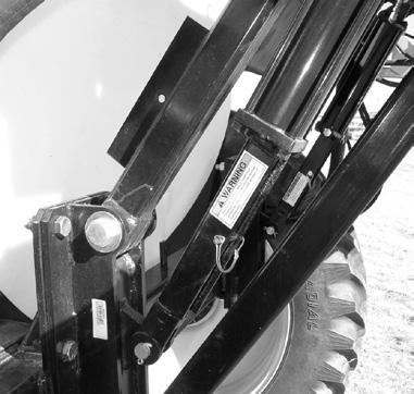
15 Boom Operation Unfolding the Boom Boom Operation Assure that the area is clear of all people before unfolding boom. Failure to do so could cause bodily injury to anyone hit by an unfolding boom. The first time the boom is operated should be in an open area so that any air in the hydraulic system can be purged from the lines. Air in the lines can cause erratic or excessive speed in unfolding. Move the sprayer to a flat area with sufficient clearance to unfold the boom. Figure B2 Raising Boom Boom Chain > Hi-Lift Lock > < Hi-Lift Lock < Boom Rest Figure B1 Boom Chains Figure B3 Hi-Lift Lock Installed Hi-Lift Lock Stored The boom control panel contains three major sections: the left boom controls, the right boom controls and the combined boom controls. Chains must be removed before unfolding boom. Failure to do so will result in damage to the boom. Remove the chains from the boom before unfolding. The transport locks must be removed from the Hi-Lift linkage to allow the boom to lower to the operating position. The boom hydraulics are activated by the tractor hydraulic system, but controlled by the boom control panel. The tractor remote should be set to run at ¼ to ½ speed and should be shifted to the pressure detent position for normal operation. Activate the boom lift switch on the boom control panel (as shown in Fig. B2) to raise the boom and allow the locks to be removed. Remove the Hi-Lift locks from the cylinders and store on the upper link. When moving from field to field, return the locks to the transport position and lower the boom onto the locks to reduce strain on the boom and lift components. 11 With the boom chains removed and the sprayer in an open area, the boom is ready to be unfolded. It is possible that air could be in the hydraulic lines the first time the boom is unfolded. Note: Be aware that air in the lines can cause the boom to unfold erratically or with excessive speed. Figure B4 Boom Control Panel


16 Boom Operation Push the tilt switch up for each boom to raise the boom out of the boom rests. The individual boom switches on the control panel operate in the desired direction of travel i.e., push the fold switch toward the outside of the panel to fold the boom out, or push the tilt switch up to raise the boom section. Figure B7 Unfolding Right Breakaway Section Unfold and fold the boom several times to purge any air from the hydraulic lines. After the initial fold/unfold cycle, the combined control can be used to fold/unfold both wings simultaneously. Figure B5 Activating Tilt Switch Raises Wing Unfold the inner wings of the right boom by engaging the right boom fold switch. Repeat with the left boom switch. Figure B8 Unfolding Both Wings With Combined Switch Tilting the Boom The boom can be tilted by activating the tilt switch on either wing. Push the switch up to raise the wing; push the switch down to lower the wing. The combined tilt switch will tilt both wings simultaneously. Figure B6 Unfolding Right Boom Activate the right outer fold switch to fold the right outer wing out. Repeat with the left outer wing. 12 Figure B9 Activating Tilt Switch Raises Wing


17 Sprayer Operation Figure B10 Tilted Left Wing Folding One Side of the Boom From time to time it may be necessary to fold one wing and spray with the rest of the boom. Use the single wing controls to fold the outer wing, then tilt the wing so that the folded section will clear the trailer tire as it is folded. Fold the primary wing by pushing the individual wing fold switch in. Cradle the boom in the boom rest when folded by tilting the boom down. Figure B12 Folded Wing When one wing is folded, the other wing will probably drop since the boom is then unbalanced. Tilt the unfolded wing up to bring it back to level. Single wing spraying should only be for short distances, at slow speeds. With the boom unfolded, check along the length of the boom to assure that the boom is straight. If one or more sections of the boom is not straight, refer to pages for instructions on how to straighten the boom. < Boom Rest boom sections should be aligned Figure B11 Wing In Boom Rest Figure B13 Aligned Boom Center Section Inner Wing Outer Wing Breakaway Figure B14 Spray Wyng II Boom Sections 13


 Main > Agitator > Return > Figure C3 1,000 Field Sprayer Manifold 1. Main Tank Valve 2. Main Tank Fill Valve 3. Return Valve 4. Agitation Valve 5.")
18 Sprayer Operation Sprayer Operation VersaTrail, 1600 Manifold The VersaTrail and 1600 are equipped with a valve manifold to make filling, mixing and cleaning easier and safer. An instructional decal is included as well. to the hoses are required. For operation, the valves should be open. The main tank valve is a three-way valve; vertical is off, handle rear (shown) is normal flow, handle front is drain (with plug removed). < Instructional Decal Figure C1 VersaTrail, 1600 Manifold 1. Tank Source Valve -- controls main tank and fresh water tank 2. Fresh Water Tank Fill Valve 3. Main Tank Fill Valve 4. Fresh Water Hygiene Valve 5. Agitation Valve 6. Return Valve 7. Boom Flush Valve 8. Boom Line Strainer (discharge) 9. Supply Line Strainer (suction) 10. Handler Drain Valve 11. Handler Rinse Valve 12. Jug Rinse Valve (not shown) Main > Agitator > Return > Figure C3 1,000 Field Sprayer Manifold 1. Main Tank Valve 2. Main Tank Fill Valve 3. Return Valve 4. Agitation Valve 5. Supply Line Strainer (suction) 6. Boom Flush Valve Initial Sprayer Check-out Load about 300 gallons of clean water into the spray tank. Add a few gallons of water to any other tanks such as the Handler or fresh water tank. VersaTrail, To add water to the spray tank, remove the cap from the Main Tank Fill quick coupler and couple the supply hose. Open spray tank fill valve (leave other valves closed) (Figure C1). Open the supply line and add desired amount of water. 1,000 Field Sprayer -- To add water to the spray tank, remove the cap from the Main Tank Fill quick coupler and couple the supply hose. Open main tank fill valve and main tank valve (leave other valves closed) (Figure C3). Open the supply line and add desired amount of water. Figure C2 VersaTrail, 1600 Open Tank valves The VersaTrail main tank is equipped with valves below the sump. These valves will usually only be closed when repairs 14 Do not add any chemical to any tank until the sprayer has been fully checked for leaks.


19 Sprayer Operation Open ball valves to allow water to gravity flow through the system. Check for any leaks. Close all ball valves except the main ball valve between the spray tank and the pump. It is important to flush the boom before installing the spray tips. the agitator ball valve on the spray tank. Engage the pump and open the valves to bring the boom up to operating pressure. With the boom spraying, check all plumbing connections for leaks. Make sure that all tips are spraying a uniform pattern. Note: The hydraulic fluid flow supplying the pump must be set the first time the pump is engaged and anytime a different hydraulic circuit or tractor is used. Before engaging the pump, turn the hydraulic adjustment to its lowest setting for that particular circuit. With the return and boom valves turned off, engage the hydraulic lever and slowly increase the hydraulic fluid flow until the boom pressure gauge reads not more than 100 psi. Figure C4 Adjusting hydraulic fluid flow Set the controller to manual. Activate the valve for each boom section so that water is flushed through open nozzle bodies. Turn the pump off once the boom is flushed. See Figure C5. Figure C6 Installing tip screen and spray tip Note: The return valve should be opened fully only when mixing chemical in the main tank. This valve can be partially opened during spraying to control the pump pressure. Fully opening during spraying will prevent the boom from achieving operating pressure. Turn the pump off, close the spray tank ball valve and clean out the main strainer. Filling The Fresh Water Tank Only potable water should be added to the fresh water tank. Addition of contaminated water could cause bodily injury when used for washing hands, face and eyes. Figure C5 Flushing boom with clean water VersaTrail, Remove the cap from the fresh water tank fill valve and couple the supply line. Open the fresh water tank fill valve and open the supply line. When the tank is full, close the fresh water tank fill valve before disconnecting the supply hose. Install the spray tips and tip screens in each nozzle body. Note: Some sprayers may be equipped with double line strainer, therefore, making tip screens unnecessary. Open 15 1,000 Field Sprayer -- The fresh water tank is filled by inserting a supply hose through the fillwell on top of the tank.


20 Sprayer Operation < Open Fresh Water Tank Valve Loading Spray Material Into The Sprayer Fresh Water > Supply Line Figure C7 Filling Fresh Water Tank The fresh water tank can be used for flushing the pump and boom as well as supplying hygiene water for washing hands, face and, if necessary, eyes. Open the fresh water hygiene valve as needed to wash hands, face or to flush eyes if contacted with chemical. Always wear protective clothing, i.e. apron, face shield, gloves and respirator, when handling any chemicals. Failure to do so will risk chemical exposure to your body resulting in sickness, injury or possibly death. Spraying solution can be loaded by either filling with a premixed solution or mixing the chemical and carrier on the sprayer. Most trailer mounted sprayers have a Handler mix tank mounted on the trailer. Remove the cap from the Quick Fill coupling on the Main Fill valve and attach the supply hose to the coupling. Open the main fill ball valve and the supply line. Fill the spray tank with water, fertilizer, etc., less the amount of chemical to be added. < Open Main Fill Valve < Supply Line Valve < Closed Main Tank Valve Figure C8 Washing Hands From Fresh Water Tank Faucet Figure C9 Filling Spray Tank Handler tank should always be empty except when adding chemical to the sprayer. Raising and lowering the tank with chemical is dangerous and greatly increases the possibility of chemical exposure to your body resulting in sickness, injury or possibly death. 16

, the agitation valve and the return valve.")


21 Sprayer Operation Mixing Chemical Through the Handler System Pull the lock pin and lower the Handler tank. The Handler system includes a venturi in the return line that draws chemical in downstream of the pump so that concentrate chemical does not pass through the pump. Open the tank source valve for the main tank (handle pointed up), the agitation valve and the return valve. Make sure that the boom valves are closed. Engage the pump. < Lock Pin Open Agitator Valve > < Open Return Valve < Open Main Tank Valve Figure C10 Handler Tank In Stowed Position Handler > Rinse Valve < Handler Jug Rinse Valve < Handler Drain Valve Figure C12 Valve Setting For Educting Chemical The Handler system is equipped with a knife to puncture the chemical jugs for easy rinsing and proper disposal. Set the chemical jug on the knife with enough force to puncture the jug (Figure C14). Figure C11 Handler Tank Lowered & Ready To Fill Figure C13 Stabbing Jug On Handler Knife 17


22 Sprayer Operation Agitation and Return Lines The trailer sprayers are equipped with an agitator and a return line to aid in mixing chemical and keeping it in suspension. The agitator valve should be open for most spraying and mixing operations to keep the chemical in suspension. The return valve should be opened to mix large volumes of chemical such as when the tank is refilled. The return valve should be closed completely or open just slightly when spraying. An open return valve will not allow the boom to reach operating pressure. Figure C14 Rinsing Empty Chemical Jug Open the Handler drain valve. The venturi will educt the chemical into the return line. Once the chemical jug is empty, and before removing the jug from the knife, open the jug rinse valve. Close the jug rinse valve before removing jug. Open the Handler rinse valve for several seconds to rinse out any chemical concentrate. Once the Handler tank is empty, close the Handler drain valve to prevent backflow of solution through the tank agitator valve. Continue to circulate the solution for several minutes with the return and agitation valves open. Close the return valve before beginning spraying operations. < Open Agitator Valve < Open Return Valve < Open Main Valve Figure C16 Open Agitation And Return Valves To Mix Chemical Raise and secure the Handler into the transport position when mixing operations are complete. < Rinse Nozzle Return> < Anti-Vortex Drain < Agitator Figure C15 Rinsing Handler Tank Figure C17 Agitator and Return Inside Tank 18


23 Sprayer Operation Operating The Sprayer With the sprayer in the field, unfold the boom as described on pages Open the main tank valve and the agitator valve. Engage the pump, activate the master switch on the controller and begin spraying. The boom must always operate perpendicular to the ground. Failure to do this can cause excessive yaw movement and can damage the boom. Levelling Trailer Sprayers Adjust the drawbar clevis to level the spray trailer. Agitator Valve > Open Figure C20 Valve Set For Spraying < Main Tank Valve Open Tilting The Spray Wyng II Boom The Spray Wyng II boom is designed to tilt up to clear obstructions or to fit the contour of the land. Tilting the boom is as simple as activating the tilt switch for the appropriate wing. Figure C18 Trailer Should Run Level Setting Boom Height With the boom unfolded and the transport locks removed, activate the main lift switch to lower the boom to the desired boom height. Figure C21 Activating Right Wing Tilt Switch Reduced Width Spraying The Spray Wyng II boom may be equipped with boom plumbing in 3, 5, or 6 sections. Each configuration may be ordered to meet the needs of different operators. Figure C19 Setting Boom Height Activating The Sprayer If you are using an automatic controller, refer to the owner s manual for instructions on setting the controller for the desired spray volume and speed. Single Side Fold Occasionally, one side of the boom must be folded to spray around an obstruction or to spray a reduced width area. See page 15 for instructions on how to fold one section of the boom. Turn off the folded sections on the controller in order to continue to spray with the unfolded boom sections. 19

 by folding the outer wings and turning off two sections of the five section boom plumbing.")


 is a machined bolt")
24 Sprayer Operation Breakaways The Spray Wyng II is protected by an auto-reset shock that will reset the wing tip once the obstruction is cleared. Figure C22 Single Side Spraying Folded Outer Wing Spraying The Spray Wyng II 80 or 90 can be reduced to a 49 spraying width (100 boom ) by folding the outer wings and turning off two sections of the five section boom plumbing. Figure C25 Wing Tip Breakaway If the breakaway wing tip becomes slack, tighten the coil spring. < Coil Spring Figure C23 Folded Outer Wings Activate the combined outer fold switch on the control panel to fold/unfold the outer wings. Figure C26 Auto-Reset Shock The Spray Wyng II is also equipped with a shear bolt that protects the inner and outer wings if an obstruction is hit inside the breakaway. The shear bolt (P/N W8325- SHEAR1HD-KIT , Red; W8325-SHEAR1-KIT -- 60, 80, Blue) is a machined bolt and should be ordered from Wylie Customer Service. Do not replace the shear bolt with a standard bolt. Figure C24 Unfolding Outer Wings Be aware that when the sprayer is operated with the breakaways folded, the boom is only protected by the shear bolts. Extra care should be taken to avoid obstructions. 20


25 Sprayer Operation End Of The Day Procedure Some chemicals require the boom to be flushed at the end of the day to prevent corrosion in the pump or settling of chemical in other components. Open the fresh water tank valve and close all other valves. Set the controller for manual operation, engage the pump and open the boom valves to allow fresh water to flush the pump and boom. Breakaway Shear Bolt > Figure C27 Breakaway Shear Bolt Operating Recommendations Be aware of any obstructions, animals or people while spraying. The Spray Wyng II booms extends on either side as you spray. While the boom is equipped with a breakaway to help protect the boom, damage or injury can occur in a collision. Open Fresh Water Tank Valve > Figure C28 Setting Valves To Flush With Fresh Water The Spray Wyng II is designed to operate at a top speed of 15 mph. Care and common sense, however, must be used to determine the optimum speed for a particular spraying operation. Factors such as rough surface conditions, hillsides, terraces and turns will require a slower operating speed. When spraying with one side of the boom folded, spraying speeds should be at 6 mph or less as the boom is in a locked position and does not have the flex that is available in the full fold-out position. Listed below are several things you should check to maintain trouble free spraying: *Make sure spray tips are sized for the desired volume and speed. (Refer to the TeeJet Catalog or Wylie web site ( if using TeeJet tips.) *Clean pump strainer as needed to maintain adequate flow to the pump. *Keep tractor hydraulic level full for consistent pump operation. *Keep the agitator ball valve open and the return line ball valve closed or slightly open while spraying. 21 The VersaTrail sprayer is equipped with a rotary tank cleaning nozzle that cleans the spray tank when the chemical type is changed. Open the Fresh Water Tank valve and the Tank Clean valve. Engage the pump for about one minute to clean the tank. The diluted rinse fluid should be sprayed on the field or disposed of properly. Open > Spray Tank Rinse Valve Open Fresh Water Tank Valve > Figure C29 Valve Set for Rinsing Spray Tank (VersaTrail) Lower and lock into place any parking stands supplied with trailer units when unhooked from the tractor to maintain complete stability.
 Remove cap from fresh water tank valve and open ball valve to drain the fresh water tank. (4) Remove the strainer base and screen to drain the suction plumbing.")

26 Sprayer Operation Preparing The Sprayer For Storage (1) Flush the tank, pump and lines with clean water. (2) Remove cap from the main tank fill valve and open ball valve to drain the spray tank. (3) Remove cap from fresh water tank valve and open ball valve to drain the fresh water tank. (4) Remove the strainer base and screen to drain the suction plumbing. Remove pump plug to drain pump housing. (5) Remove tips and strainers from the nozzle bodies. Clean strainers and check tips for wear and damage. (6) Open controller ball valves. Allow the system to drain completely to prevent any parts from breaking due to freezing. Loosen at least one cap from each boom section to allow any water inside the nozzle bodies to drain. Check any fittings where water can collect and disconnect to allow drainage. Reconnect all fittings and ensure tightness once system is drained. (7) For further protection, pump environmentally safe antifreeze or winter grade windshield washing fluid into the lines. Sprayer Transport Before transporting the sprayer on any public roads, make sure that the sprayer lights are plugged into the tractor, the boom is lowered into the boom rest, and the boom lock chains are pinned. Light Plug > Figure C30 Remove Strainer Base To Drain Tank Figure C31 Light Plug and Boom Lock Chain 22
 and discharge (boom line) side of the pump as well as tip strainers.")

 Secondary strainers are located at each nozzle.")
27 Maintenance Maintenance and Adjustment Clearing Debris From System Occasionally, it may become necessary to clear debris from the system. The VersaTrail, and 1600 are equipped with strainers on both the suction (supply line) and discharge (boom line) side of the pump as well as tip strainers. The Field Sprayers have a strainer on the suction side and tip strainers. < Strainer Screen < Strainer O-Ring Wear chemical resistant rubber gloves when cleaning the system. Failure to do so can cause sickness or death. Read safety information provided by chemical manufacturer for proper handling procedures. (1) Cleaning Suction (Supply Line) Strainer -- Close all ball valves. Remove the strainer s cap and take out wire mesh screen. Take care that the strainer O-ring stays in place on the cap. Clean and replace the screen. Turn the main tank ball valve on. < Strainer Cap Figure D2 Cleaning Boom Line Strainer (3) Secondary strainers are located at each nozzle. To clean, remove the nozzle cap (tip and gasket come out with cap). Remove strainer from the nozzle body. Clean and replace. Closed Main Tank Valve > < Strainer Screen < Strainer Cap Figure D1 Cleaning Supply Line Strainer (2) Cleaning Discharge (Boom Line) Strainer -- Close all ball valves. Remove the strainer s cap and take out wire mesh screen. Take care that the strainer O-ring stays in place on the cap. Clean and replace the screen. Turn the main tank ball valve on. Figure D3 Removing Tip Strainer (4) Discard and replace damaged strainers. It is possible for debris to get past the strainers and clog the orifice of the tip. Clean the tips with a TeeJet cleaning brush only. Using wire, pocketknives or wire brushes can cause damage to the tip altering spray volume or pattern. 23


28 Maintenance Adjusting The Boom The Wylie Spray Wyng II boom was manufactured to exacting specifications and should not need adjustment initially. It may become necessary, however, during the life of the boom to make adjustments to the folding/unfolding cycle or the level control. Breakaway Outer Wing Inner Wing Figure D4 Spray Wyng II Boom Sections Center Section Fold/Unfold Adjustment The boom should be adjusted so that it is straight when completely unfolded. In rare cases, it may be necessary to extend the length of the cylinder by extending the cylinder clevis. Remove the cylinder pin and screw the clevis out as needed. Adjusting Wing Relief Valve The Spray Wyng II boom is equipped with a relief valve for each side of the boom which works like an automatic reset. A fast stop or high speed turn can cause one or both wings to swing forward. As the sprayer moves through the field, the natural action allows the relief valve to equalize the hydraulic fluid in the fold cylinder and reset the boom against the boom stop. The relief valve is preset at the factory and should not need adjustment. However, if the boom swings forward but does not reset without activating the hydraulics, the relief valve may need adjustment. It is recommended that you contact the Wylie Service Department for specific instructions or have a factory service technician make the adjustment. Always adjust the inner wing first, then straighten the breakaways. Always make sure that the fold cylinders are fully extended before making adjustments. Make any adjustments to align the unfolded boom first, then make the adjustments to the folded boom. Adjusting Inner Wing The inner wing unfold cycle is controlled by the setting of the limit bolt. The limit bolt should be set so that the primary wing is aligned with the center section when the cylinder is fully extended. Extra shims are located between the nut and frame. To adjust the boom in remove the nuts and move 1 or 2 shims to the other side of the frame, which lengthens the bolt. Retighten the nuts and check alignment. Shims > < Fold Cylinder < Fold Hinge Removing Cap Figure D6 Adjusting Relief Valve Overtightening of the relief valve can cause excessive pressure and damage in the hydraulic system. Aligning The Breakaway The breakaway is controlled by an auto-reset shock. The breakaway is equipped with a poly spring cushion and a coil spring. The coil spring should maintain some pressure against the poly spring. Adjust the setting of the set bolt to align the breakaway. Limit Bolt > Figure D5 Inner Wing Adjustment 24


29 Maintenance Coil Spring > Cable < Shock Poly Spring > < Set Bolt < Poly Pad Figure D7 Breakaway Adjustment If the breakaway becomes loose, check the setting of the coil spring, poly spring and condition of the shock. < Coil Spring Figure D9 Outer Wing Adjustment Adjusting Tilt Cylinder The tilt cylinder raises the inner wing to an approximately 15º angle. The wing should be level when the tilt cylinder is completely extended. To adjust the wing, extend the tilt cylinder. Lower the complete boom till the tilt section is resting on a support such as a sawhorse. Remove the pin from the cylinder clevis, screw the clevis in or out as needed, then replace the pin. Shock > < Poly Spring < Cylinder Clevis Figure D8 Breakaway Reset Adjusting Outer Wing The outer wing, as it unfolds vertically, should come to rest on the same level with the center section and inner wing. The outer wing rests against a poly pad. If the outer wing unfolds past level, shims can be placed between the poly pad and the frame. Figure D10 Wing Tilt Adjustment 25


30 Maintenance Adjusting Spray Wyng II Boom The All-Directional suspension will keep the boom level in most situations. If the boom is not level when unfolded, check it verify that mud or some other object is not weighing down one end of the boom or that the tilt cylinders are not totally extended. The Spray Wyng II is equipped with a set of springs at the bottom of the pivot frame. Outer Wing Boom Rest The outer wing boom rest can be adjusted laterally to align with the boom. Loosen the adjustment bolts and slide the rest to align with the boom. Outer Boom Rest > Adjustment Slot > Center Section < Jam Nut < Pivot Frame < Springs Figure D12 Outer Wing Boom Rest Figure D11 Boom Adjustment Springs If the boom is not level, loosen the jam nut on both sets of springs. Tighten the adjustment nut on the side of the boom that is higher. Count the number of turns so that the adjustment nut on the opposite side can be loosened the same number of turns. The springs should maintain the same tension. Manually raise and lower the end of boom two times and let the boom settle. Check to see if the boom is level. Adjust further if needed. Tighten the jam nuts when the boom is level. VersaTrail/Single Axle Hitch Adjustment The spray trailers feature an adjustable hitch to maintain a level trailer and boom with different tractor drawbar heights. With the trailer pinned to the tractor drawbar and the parking jack supporting the tongue, remove the two hitch pins. Level the trailer with the jack, then insert and lock the pins. Figure D13 Adjust Hitch To Level Trailer 26


31 Maintenance Wheel Spacing VersaTrail/1,000 Gal. Single Axle The wheel spacing on the VersaTrail and 1,000 gal. single axle trailers are adjustable from An optional axle is available for spacing. The 14.9xR46 tractor style tires can be adjusted through the full adjustment. Optional 24.5x32 hi-flotation tires can be spaced Check that all people are clear of the trailer when the axle is moved in or out. Failure to secure the frame to a solid support can result in the sprayer sliding off of the support causing severe injury or death to anyone under the sprayer. Spray Wyng II Tandem Axle Trailer The Spray Wyng II Tandem Axle Trailer with x 24 tires, can be adjusted from 66 to 120 spacing for varying row widths. Attach the sprayer to the tractor drawbar and set the brake on the tractor. Using sturdy blocks to support a hydraulic jack, raise one side of the trailer. Loosen the strut bolts and move the wheels to the desired location. Moving the wheels to the narrow setting of 66 requires reversing the strut so that the strut and walking beam are on the outside and the tires are on the inside. Make sure that the trailer is attached to a tractor for stability and if possible, unfold the boom. Raise one side of the trailer and secure on a solid support. Loosen the lock bolt and the U-bolt on the axle to be moved. Slide the axle to the desired location and tighten the lock bolt and U-bolt. Repeat on the opposite side. Lock Bolt > U-Bolt > Adjustment Slot > Figure D15 Spray Wyng Tandem Axle Adjustment Figure D14 VersaTrakr/VersaTrail Axle Adjustment 27


32 Lubrication Recommended Lubrication Boom Suspension (1 grease zert) Grease every week Inner Wing/Tilt Hinge (3 grease zerts per hinge) Grease daily Walking Beam Pivot Grease every week Wheel Hub Assemblies Repack every year 28

 Grease")
33 Lubrication Recommended Lubrication Hi-Lift Linkage Grease every week 8 grease zerts Outer Wing Hinge (2 grease zerts per hinge) Grease daily 29
34 Troubleshooting Troubleshooting Guidelines Problem Cause Solution Pump Will Not Operate Pump will not move solution Pump output is very low; erratic Controller does not operate Boom ball valves do not operate (1) Hydraulic lines not attached (2) Tractor hydraulic lever not engaged (3) Hydraulic lines in wrong ports (4) Malfunctioning hydraulic motor (5) Tractor hydraulic flow adjusted too low (1) Spray tank empty (2) Main tank ball valve closed (3) Plugged strainer (4) Malfunctioning pump (5) Pump is air locked (1) Spray tank low; air getting in pump (2) Tank ball valve partially closed (3) Plugged strainer (4) Collapsed suction hose (5) Air leak in suction system (6) Air leaking through open Mix n Fill ball valve (7) Malfunctioning pump (8) Air leaking through open fresh water tank valve (1) Not connected to 12V system (2) Improperly connected to 12V system (3) Improper ground connection (4) Fuse blown on controller (5) Master switch turned off (6) Boom switches off (7) Controller not programmed properly (8) Malfunctioning controller (1) Not connected to controller (2) Not connected to independent 12 volt source (3) Ball valve stuck (1) Insert hydraulic lines in tractor circuit (2) Engage lever (see tractor instructions) (3) Change hydraulic line locations (4) See pump owner s manual or contact Wylie (5) Adjust tractor flow higher (1) Fill tank (2) Open ball valve (3) Clean strainer screen and inspect cap O-ring (4) See pump owner s manual or contact Wylie Spray Center (5) Open drain cocks to bleed air and check for air leaks between tank and pump (1) Fill tank; bleed air by removing top pump plug (2) Open ball valve (3) Clean strainer screen and inspect cap O-ring (4) Replace suction hose (5) Tighten fittings and clamps; Check for cracked or cut components; Apply thread sealant to pipe threads. (6) Close ball valve (7) See pump owner s manual or contact Wylie Spray Center (8) Close fresh water tank valve (1) Connect to constant power source, such as the starter (2) Check hot and ground connections (3) Do not ground to cab. Cab is usually mounted on rubber bushings (4) Replace fuse (5) Turn on switch (6) Turn boom switches on (7) See controller owner s manual for instructions. (8) See controller owner s manual or contact Wylie Spray Center (1) Connect wires to controller cable (2) Connect red wire to 12 volt source (3) Flush entire spray system with clean water 30
35 Troubleshooting Troubleshooting Guidelines Problem Cause Solution No output or insufficient pressure at spray tip(s) No output from one section of sprayer Spray pattern uneven at one tip Spray solution not mixing well Boom not level Boom fold/tilt functions will not operate (1) Air leak in suction side of system (2) Problem with pump (3) Control valve malfunctioning (4) Malfunctioning controller (5) Nozzle strainer(s) or tip(s) clogged (6) Spray tips not proper size (7) Return valve open too much (8) Pressure shows on gauge but there is no pressure on outside tips on boom (1) Boom switch turned off (2) Malfunctioning ball valve (3) Malfunctioning boom switch (1) Trash in tip orifice (2) Damaged tip orifice (3) Worn or damaged tip (1) Agitator closed (2) Clogged or damaged agitator (3) Chemical incompatibility (1) One end of boom weighted with mud, etc. (2) Tilt cylinders not set uniformly (3) Tension springs not set properly (1) Hydraulic circuit not in pressure detent position (2) Boom control panel not powered (1) See above (2) See above (3) Replace control valve; Replace pressure adjusting switch; See controller owner s manual or contact Wylie Spray Center (4) See above (5) Clean strainer(s) or tip(s), or replace (6) Replace with proper tip (7) Partially or completely close return valve (8) Remove outside tips from both sides of boom and flush entire system with clean water (1) Turn boom switch on (2) Repair or replace ball valve (3) Replace boom switch (1) Clean tip (2), (3) Replace tip (1) Open agitator ball valve (2) Replace agitator assembly (3) Mix a small sample in a 5 gal. bucket first (1) Clean boom (2) Activate tilt cylinder to level boom (3) Tighten one spring and loosen other spring uniformly to maintain constant tension and level boom (1) Move hydraulic circuit in pressure detent position for continuous operation (2) Check hot/ground connections for panel One fold/tilt function will not operate (1) Malfunctioning panel switch (1) Replace panel switch Inner wing does not fold out in line with center section (1) Inner fold cylinder clevis needs adjustment (2) Limit bolt needs adjustment (1) Shorten clevis to fold in; lengthen clevis to fold out (2) Lengthen limit bolt to fold in; shorten limit bolt to fold out 31
36 Troubleshooting Troubleshooting Guidelines Problem Cause Solution Breakaway not in line with inner and outer wings (1) Poly spring set bolt needs adjustment (1) Loosen set bolt to move breakaway back Tighten set bolt to move breakaway forward Breakaway section swings excessively (1) Coil spring without tension (2) Poly spring needs adjustment (1) Adjust coil spring for tension (2) Adjust poly spring set bolt to increase tension from coil spring With one wing folded, boom is unlevel (1) Unfolded wing not tilted (1) Tilt unfolded wing up until level Hi-Lift linkage will not lower (1) Transport locks in place (1) Raise boom off transport locks; remove locks and store on frame Boom bounces excessively (1) Excessive speed for ground conditions (1) Slow ground speed Boom bounces hard -- does not float (1) Nitrogen charged accumulator has lost charge (1) Contact Wylie Service to have accumulator recharged Boom leans toward front or rear (1) Spray trailer is not level (1) Lower jack to support tongue, raise or lower hitch in tongue 32
Coulter Applicator. Operator s & Parts Manual R0 Printed In The USA Specifications & Design Subject To Change Without Notice!
 Coulter Applicator Operator s & Parts Manual 4-15-18 17-011R0 Printed In The USA Specifications & Design Subject To Change Without Notice! Warranty Information This equipment was carefully designed and
8420, VSB, 8220 Boom. Operator s & Parts Manual R4 Printed In The USA Specifications & Design Subject To Change Without Notice!
 8420, VSB, 8220 Boom Operator s & Parts Manual 4-1-18 05-08R4 Printed In The USA Specifications & Design Subject To Change Without Notice! Warranty Information A Message To The Owner And Operator This
Poultry House Sprayer
 Poultry House Sprayer Operator s & Parts Manual 5-10-09 09-02R1 Printed In The USA Specifications & Design Subject To Change Without Notice Warranty Information A Message To The Owner And Operator This
Turf Wyng Sprayer. Operator s & Parts Manual R1 Printed In The USA Specifications & Design Subject To Change Without Notice!
 Turf Wyng Sprayer Operator s & Parts Manual 3-1-08 04-29R1 Printed In The USA Specifications & Design Subject To Change Without Notice! Warranty Information A Message To The Owner And Operator This equipment
Vineyard Sprayer. Operator s & Parts Manual R0 Printed In The USA Specifications & Design Subject To Change Without Notice!
 Vineyard Sprayer Operator s & Parts Manual 6-1-17 17-004R0 Printed In The USA Specifications & Design Subject To Change Without Notice! Warranty Information This equipment was carefully designed and manufactured
Side Mount Tanks Front Mount Tanks
 Side Mount Tanks Front Mount Tanks Operator s & Parts Manual 12-26-18 16-05R2 Printed In The USA Specifications & Design Subject To Change Without Notice! Warranty Information A Message To The Owner And
Dust Killer Auto-Skid Ice Blitzer Auto-Skid
 Dust Killer Auto-Skid Ice Blitzer Auto-Skid Operator s & Parts Manual 3-1-18 06-01R2 Printed In The USA Specifications & Design Subject To Change Without Notice! Warranty Information A Message To The Owner
DOT Trailers R1 Printed In The USA Specifications & Design Subject To Change Without Notice!
 DOT Trailers 5-1-09 05-18R1 Printed In The USA Specifications & Design Subject To Change Without Notice! Warranty Information This equipment was carefully designed and manufactured to give you dependable
Non-DOT Nurse Trailer Cone Trailer Hi-Rise Trailer Steerable Trailer Tilt Trailer
 Non-DOT Nurse Trailer Cone Trailer Hi-Rise Trailer Steerable Trailer Tilt Trailer Operator s & Parts Manual 5-1-13 06-25R4 Printed In The USA Specifications & Design Subject To Change Without Notice Warranty
OWNER S MANUAL Model: TR-40-EX ( ) (40 Gallon Lawn & Garden Trailer Sprayer w/5-nozzle Boom Assembly)
 (40 Gallon Lawn & Garden Trailer Sprayer w/5-nozzle Boom Assembly)") OWNER S MANUAL Model: TR-40-EX (5301338) (40 Gallon Lawn & Garden Trailer Sprayer w/5-nozzle Boom Assembly) Technical Specifications 40 Gal. Corrosion-Resistant Polyethylene Tank 12 Volt Diaphragm Pump,
OWNER S MANUAL Model: TR-40-EX (5301338) (40 Gallon Lawn & Garden Trailer Sprayer w/5-nozzle Boom Assembly) Technical Specifications 40 Gal. Corrosion-Resistant Polyethylene Tank 12 Volt Diaphragm Pump,
Operator and Parts Manual
 Operator and Parts Manual High-Clearance Sprayer Model 1200 / 850 122010 SXL-25029 Introduction High-Clearance Sprayer Farm King Sprayers have been designed to provide many years of profitable and dependable
Model No. LG55-3PT 55 Gallon Sprayer 3 Point Lawn & Garden Sprayer Model No. LG27-3PT 25 Gallon Sprayer GENERAL INFORMATION
 5300587 Model No. LG27-3PT 25 Gallon Sprayer 5300576 Model No. LG55-3PT 55 Gallon Sprayer 3 Point Lawn & Garden Sprayer Join the center boom to the carrier frame with the two u-bolts, and flange locknuts.
LEWIS WINDROWER OWNER / OPERATOR MANUAL
 LEWIS WINDROWER OWNER / OPERATOR MANUAL MODEL # WR-1 WINDROWER Manufactured by: LEWIS BROTHERS MANUFACTURING, INC. Post Office Box 146 Baxley, GA 31513 Tel: (912) 367-4651 Fax: (912) 367-3958 2-21-14 1
OWNER S MANUAL. Model: LG-30-TRL ( ) (30 Gallon Lawn & Garden Trailer Sprayer)
 (30 Gallon Lawn & Garden Trailer Sprayer)") OWNER S MANUAL Model: LG-30-TRL (5302317) (30 Gallon Lawn & Garden Trailer Sprayer) Technical Specifications 30 Gal. Corrosion-Resistant Polyethylene Tank 12 Volt Diaphragm Pump, 2.1 g.p.m. 60 psi 15 Ft.
OWNER S MANUAL Model: LG-30-TRL (5302317) (30 Gallon Lawn & Garden Trailer Sprayer) Technical Specifications 30 Gal. Corrosion-Resistant Polyethylene Tank 12 Volt Diaphragm Pump, 2.1 g.p.m. 60 psi 15 Ft.
Model: ATVTS-60-12V 60 Gallon Trailer Sprayer W/7 Nozzle Boom ASSEMBLY / OPERATION INSTRUCTIONS / PARTS
 5301192 Model: ATVTS-60-12V 60 Gallon Trailer Sprayer W/7 Nozzle Boom ASSEMBLY / OPERATION INSTRUCTIONS / PARTS ASSEMBLY INSTRUCTIONS The sprayer is assembled except for the pressure gauge, axle, wheels
OWNER S MANUAL. Model: TR-40-GAS ( ) (40 Gallon Lawn & Garden Trailer Sprayer w/5-nozzle Boom Assembly) Technical Specifications
 (40 Gallon Lawn & Garden Trailer Sprayer w/5-nozzle Boom Assembly) Technical Specifications") OWNER S MANUAL Model: TR-40-GAS (5301339) (40 Gallon Lawn & Garden Trailer Sprayer w/5-nozzle Boom Assembly) Technical Specifications 40 Gal. Corrosion-Resistant Polyethylene Tank 5.5 HP Briggs & Stratton
OWNER S MANUAL Model: TR-40-GAS (5301339) (40 Gallon Lawn & Garden Trailer Sprayer w/5-nozzle Boom Assembly) Technical Specifications 40 Gal. Corrosion-Resistant Polyethylene Tank 5.5 HP Briggs & Stratton
180 Lake Ave North Paynesville, MN Phone: (320) MASTER MANUFACTURING MASTER GARDNER
 MASTER MANUFACTURING MASTER GARDNER") 180 Lake Ave North Paynesville, MN 56362 Phone: (320) 340-6464 www.master-mfg.com MASTER MANUFACTURING MASTER GARDNER Part Number PCD-E3-009B-MM July 2017 Note: Do not return product to the distributor/dealer
180 Lake Ave North Paynesville, MN 56362 Phone: (320) 340-6464 www.master-mfg.com MASTER MANUFACTURING MASTER GARDNER Part Number PCD-E3-009B-MM July 2017 Note: Do not return product to the distributor/dealer
Smart-Till. Models ST101, ST151, ST203, and ST303. HCC, inc st Avenue Mendota, IL
 Owners Manual Smart-Till Models ST101, ST151, ST203, and ST303 HCC, inc. 1501 1st Avenue Mendota, IL 61342 815-539-9371 www.hccincorporated.com C-1159 May 2010 Safety Most work related accidents are caused
03-SERIES 4 & 6-ROW RIGID & FOLDING PEANUT VINE CONDITIONER OPERATOR S MANUAL THIS MANUAL TO ACCOMPANY MACHINE
 03-SERIES 4 & 6-ROW RIGID & FOLDING PEANUT VINE CONDITIONER OPERATOR S MANUAL THIS MANUAL TO ACCOMPANY MACHINE PART NO. 03-OM-03 Printing Date: SEPT 2012 WARRANTY POLICY KELLEY MANUFACTURING COMPANY (KMC)
MODEL NO. UTL-60-7
 5301400 MODEL NO. UTL-60-7 12 Volt Skid Mounted Utility Sprayer ASSEMBLY / OPERATION INSTRUCTIONS / PARTS ASSEMBLY The sprayer is fully assembled at the factory. The only assembly necessary is to thread
MODEL NO. UTL Gallon 12 Volt Skid Mounted Utility Sprayer ASSEMBLY / OPERATION INSTRUCTIONS / PARTS
 5301399 MODEL NO. UTL-40-5 40 Gallon 12 Volt Skid Mounted Utility Sprayer ASSEMBLY / OPERATION INSTRUCTIONS / PARTS ASSEMBLY The sprayer is fully assembled at the factory. The only assembly necessary is
Mulcher Operators Manual
 Mulcher Operators Manual Skid Pro Attachments PO Box 982 Alexandria, MN 56308 October 2015 1 2 Contents 1. Introduction And Warranty... 4 1.1 Introduction... 4 1.2 Warranty... 4 2. Component Identification...
OWNER S MANUAL. Model: UTL-60-12V ( ) (60 Gallon Lawn & Garden Utility Sprayer w/5-nozzle Boom)
 (60 Gallon Lawn & Garden Utility Sprayer w/5-nozzle Boom)") OWNER S MANUAL Model: UTL-60-12V (5301347) (60 Gallon Lawn & Garden Utility Sprayer w/5-nozzle Boom) Technical Specifications 60 Gal. Corrosion-Resistant Polyethylene Tank Deluxe Pistol-Grip Handgun w/25
OWNER S MANUAL Model: UTL-60-12V (5301347) (60 Gallon Lawn & Garden Utility Sprayer w/5-nozzle Boom) Technical Specifications 60 Gal. Corrosion-Resistant Polyethylene Tank Deluxe Pistol-Grip Handgun w/25
CRUSTBUSTER OWNER / OPERATOR MANUAL
 CRUSTBUSTER OWNER / OPERATOR MANUAL MODEL # CB-1 CRUSTBUSTER Manufactured by: LEWIS BROTHERS MANUFACTURING, INC. Post Office Box 146 Baxley, GA 31513 Tel: (912) 367-4651 Fax: (912) 367-3958 5-2-17 1 INTRODUCTION
Operator and Parts Manual
 SXL-27039 Operator and Parts Manual 1000 Trailer Sprayer 01/2010 Introduction 1000 Trailer Sprayer TO THE OWNER Thank you for purchasing a Farm King 1000 Trailer Sprayer. Farm King Sprayers have been designed
W & A 12 ROW TOP LEVELING STACKER LEVEL BANDER
 W & A 12 ROW TOP LEVELING STACKER LEVEL BANDER NO. 3640 OPERATOR S MANUAL TO THE OWNER: Congratulations on your purchase of a new W & A Top Leveling Stacker Level Bander. Your selection is an indication
MODEL: ATV Volt, 15 Gallon ATV Mounted Sprayer ASSEMBLY / OPERATION INSTRUCTIONS / PARTS
 5300936 MODEL: ATV-15-2 12 Volt, 15 Gallon ATV Mounted Sprayer ASSEMBLY / OPERATION INSTRUCTIONS / PARTS 2.1 G.P.M. Pressure Gauge-Adjustable Pressure Range 15 Foot Handgun Hose 2 Nozzle Boom Assembly
APPLICATION EQUIPMENT. Fertilizer Applicators High-Clearance Sprayers Liquid Supply Trailer
 APPLICATION EQUIPMENT Fertilizer Applicators High-Clearance Sprayers Liquid Supply Trailer Farm King Application Equipment: Fertilizer Applicators, High-Clearance Sprayers, Liquid Supply Trailer FARM KING
MODEL NO. LG Volt Lawn & Garden Sprayer ASSEMBLY / OPERATION INSTRUCTIONS / PARTS
 5301065 MODEL NO. LG-2500-303 12 Volt Lawn & Garden Sprayer ASSEMBLY / OPERATION INSTRUCTIONS / PARTS 12 Volt Diaphragm Pump 2.1 G.P.M. Lever Handgun 15 Ft. of 3/8 Hose (Handgun) Pressure Gauge Adjustable
Deere G & GP Series Snow Wing Installation
 Deere G & GP Series Snow Wing Installation Model: Serial Number: Rev. 10/13 Rylind Manufacturing, Inc. 2801 Youngfield St Suite 250 Golden, CO 80401 Offices: 303-979-3548 Fax: 303-979-4730 www.rylind.com
TRAILER SPRAYER MODEL: 500 BW OPERATOR'S MANUAL DO NOT OPERATE THIS EQUIPMENT UNTIL THIS MANUAL HAS BEEN READ AND UNDERSTOOD.
 TRAILER SPRAYER MODEL: 500 BW OPERATOR'S MANUAL DO NOT OPERATE THIS EQUIPMENT UNTIL THIS MANUAL HAS BEEN READ AND UNDERSTOOD. Part Number: 07.09145D November 2007 MILLER-ST.NAZIANZ,INC. P.O. BOX 127 ST.
Operating and Assembly Manual
 Model 1080 Operating and Assembly Manual Midwest Equipment Manufacturing, Inc. 5225 Serum Plant Road Thorntown, IN 46071 08-02-16 SAFETY RULES Remember, any power equipment can cause injury if operated
W & A 12 ROW TOP LEVELING STACKER LEVEL BANDER
 W & A 12 ROW TOP LEVELING STACKER LEVEL BANDER NO. 3640 OPERATOR S MANUAL TO THE OWNER: Congratulations on your purchase of a new W & A Top Leveling Stacker Level Bander. Your selection is an indication
tRIPr Chief Grain Cart. Operator s Manual. Operator s Manual
 125-000-01 125-000-01 1tRIPr 1tRIPr Operator s Manual 1210 Chief Grain Cart Operator s Manual Operator s Manual TO THE DEALER Predelivery/Delivery Checklist 1210 Grain Cart PREDELIVERY/DELIVERY CHECKLIST
123 Industrial Loop Road Paynesville, MN Phone:
 123 Industrial Loop Road Paynesville, MN 56362 Phone: 1-800-864-1649 www.master-mfg.com Note: Do not return product to the distributor/dealer for warranty work. Call Master Manufacturing at (800) 864-1649
Operating and Assembly Manual
 Model 470-/H/PRO/IC Operating and Assembly Manual Midwest Equipment Manufacturing, Inc. 5225 Serum Plant Road Thorntown, IN 46071 11-11-11 SAFETY RULES Remember, any power equipment can cause injury if
180 Lake Ave North Paynesville, MN Phone: MASTER MANUFACTURING MASTER GARDNER
 180 Lake Ave North Paynesville, MN 56362 Phone: 1-800-864-1649 www.master-mfg.com MASTER MANUFACTURING MASTER GARDNER Part Number PCD-E3-009B-MM Rev 2 Dec. 2012 Note: Do not return product to the distributor/dealer
Operator s Manual. Go Galvanized! YOU'RE ALWAYS AHEAD...WITH A MODERN BEHIND.
 fall 2010 3pt & quick attach Bale spears & 3pt bale carrier Operator s Manual YOU'RE ALWAYS AHEAD...WITH A MODERN BEHIND. 318-1006-i 318-1005-i 020-1500 020-1502 P.O. Box 790 Beaumont, Tx 77704 409.833.2665
Fertilizer Applicators Utility Sprayer Liquid Supply Trailer APPLICATION EQUIPMENT
 Fertilizer Applicators Utility Sprayer Liquid Supply Trailer APPLICATION EQUIPMENT Farm King Application Equipment: Utility Sprayer, Fertilizer Applicators, Liquid Supply Trailer FARM KING PRODUCT LINE-UP
STOP. 44" High Speed Sweeper. Operator's Manual. Model No Safety Assembly Operation Maintenance Parts
 Operator's Manual STOP 44" High Speed Sweeper Model No. 486.029 DO NOT RETURN TO STORE For Missing Parts or Assembly Questions Call 1-866-576-8388 CAUTION: Before using this product, read this manual and
4745 Drill OWNER'S MANUAL (06-08) #
 #") 4745 Drill OWNER'S MANUAL (06-08) # 605865 Identification Your CrustBuster drill is identified by a Serial Number and Model Number. Record these numbers in the spaces provided in this manual and refer
4745 Drill OWNER'S MANUAL (06-08) # 605865 Identification Your CrustBuster drill is identified by a Serial Number and Model Number. Record these numbers in the spaces provided in this manual and refer
MODEL NO & UP MODEL NO & UP MODEL NO & UP MODEL NO & UP MODEL NO.
 9-0688 MODEL NO. 00-800 & UP MODEL NO. 0-800 & UP MODEL NO. 5-800 & UP MODEL NO. -800 & UP MODEL NO. 0-800 & UP SKID SPRAYER with the Centrifugal Pump FORM NO. 95-9095 SET-UP AND PARTS CATALOG SAFETY AND
Operating and Assembly Manual
 Model 380/385-IC/385-LH Operating and Assembly Manual Midwest Equipment Manufacturing, Inc. 5225 Serum Plant Road Thorntown, IN 46071 2-0916 SAFETY RULES Remember, any power equipment can cause injury
Owner's Manual. Model: ATVBK-710 ( ) (7-Nozzle Deluxe Boom Assembly w/brackets & Connecting Fittings) Technical Specifications.
 (7-Nozzle Deluxe Boom Assembly w/brackets & Connecting Fittings) Technical Specifications.") Owner's Manual Model: ATVBK-70 (3027) (7-zzle Deluxe Boom Assembly w/brackets & Connecting Fittings) (Tank NOT Included with Boom Kit) Technical Specifications 7-zzle Boom Assembly (Diaphragm/Check Valve
Owner's Manual Model: ATVBK-70 (3027) (7-zzle Deluxe Boom Assembly w/brackets & Connecting Fittings) (Tank NOT Included with Boom Kit) Technical Specifications 7-zzle Boom Assembly (Diaphragm/Check Valve
MidCap Rake MCR8 MCR10 MCR12
 MidCap Rake MCR8 MCR10 MCR12 Operator s Manual Counter Balance Valves for Steady Single Side Raking Model MCR8 3 Collection width Settings Individual Spring Adjustment THIS MANUAL MUST BE READ AND UNDERSTOOD
BUCKET SWEEPER OPERATORS & PARTS MANUAL 2852 & 3174 SERIES
 OM628 BUCKET SWEEPER OPERATORS & PARTS MANUAL 2852 & 3174 SERIES MODEL 12002-5 FOOT WIDE X 24 INCH DIAMETER (SKID-STEER) MODEL 12004-6 FOOT WIDE X 24 INCH DIAMETER (SKID-STEER) MODEL 12017-6 FOOT WIDE
Pressure Roller with 24-inch Fixed Extension - For application of architectural paints and coatings -
 Instructions Important Safety Instructions Read all warnings and instructions in this manual. Save these instructions. 311082D Pressure Roller with 24-inch Fixed Extension - For application of architectural
LG-60-3PT-WP-309-BL-TSC
 55 Model No: LG-0-PT-WP-0-BL-TSC 0 Gallon Point Lawn & Garden Sprayer W/Pump & Coupler & Boomless Boom Assembly / Operation Instructions / Parts ASSEMBLY Most of the sprayer has been assembled at the factory..
Operating and Assembly Manual
 Model 455-IC/PRO/H Operating and Assembly Manual Midwest Equipment Manufacturing, Inc. 5225 Serum Plant Road Thorntown, IN 46071 03-08-12 SAFETY RULES Remember, any power equipment can cause injury if
200 & 300 Gallon 3 Point w/5880 Nozzle ASSEMBLY / OPERATION INSTRUCTIONS / PARTS
 5300826 Model: 200-3PT-5880 5300827 Model: 300-3PT-5880 200 & 300 Gallon 3 Point w/5880 Nozzle ASSEMBLY / OPERATION INSTRUCTIONS / PARTS PUMP SYSTEM ASSEMBLY INSTRUCTIONS 1. Use a good grade of thread
OWNER S MANUAL Z SERIES TRACKS. Rev. 355_05
 OWNER S MANUAL Z SERIES TRACKS Rev. 355_05 LOEGERING 800-373-5441 15514 37 th Street SE 701-347-5441 Casselton, ND 58012 USA Fax: 701-347-4323 E-Mail: lmi@loegering.com Internet: www.loegering.com Loegering
Operating and Assembly Manual
 Model 455-IC/PRO/H Operating and Assembly Manual Palmor Products Inc. 5225 Serum Plant Road Thorntown, IN 46071 03-08-12 SAFETY RULES Remember, any power equipment can cause injury if operated improperly
WORKHORSE. Assembly / Operation Instructions / Parts 25 GALLON TRAILER SPRAYER
 WORKHORSE S P R A Y E R S Assembly / Operation Instructions / Parts GALLON TRAILER SPRAYER by PSE, a Division of Green Leaf, Inc * This sprayer is designed to be towed behind a garden tractor. MODELS #LGSTS
Bertolini Sprayer Operator s Manual
 Bertolini Sprayer Operator s Manual To ensure safe and efficient use of your new Bertolini Sprayer Please read manufacturer s operator s manual BEFORE operating sprayer. Failure to do so will void warranty
ADJUSTING PRESSURE USING THE BOOM NOZZLES OPERATION
 6. The pressure gauge is shipped in a parts bag. Thread the gauge into the tee fitting as shown on the exploded view drawing. Use a good quality thread sealant to prevent leaks. The in-line switch turns
Model ET 5000W Operation and Service Manual
 Model ET 5000W Operation and Service Manual Patented 5/16 BALL Load Capacity: 5000 lbs The ET 5000W ESCALATE TRAILER offers ground level roll-on loading and roll-off unloading of equipment with non-tilting
WORKHORSE. Assembly / Operation Instructions / Parts
 WORKHORSE S P R A Y E R S Assembly / Operation Instructions / Parts by, a Division of Green Leaf, Inc ATV 2522 MODEL # ATV 2522 DELUXE ATV 2 NOZZLE SPRAYER GENERAL INFORMATION WARRANTY / PARTS / SERVICE
OWNER S MANUAL. Model: FSUTV-45-12V ( ) (45 Gallon Lawn & Garden UTV Sprayer, Boom Ready) Technical Specifications. Assembly Instructions
 (45 Gallon Lawn & Garden UTV Sprayer, Boom Ready) Technical Specifications. Assembly Instructions") OWNER S MANUAL Model: FSUTV-45-12V (5302903) (45 Gallon Lawn & Garden UTV Sprayer, Boom Ready) Technical Specifications 45 Gal. Corrosion-Resistant Polyethylene Tank Deluxe Pistol-Grip Handgun 25 Ft. Handgun
OWNER S MANUAL Model: FSUTV-45-12V (5302903) (45 Gallon Lawn & Garden UTV Sprayer, Boom Ready) Technical Specifications 45 Gal. Corrosion-Resistant Polyethylene Tank Deluxe Pistol-Grip Handgun 25 Ft. Handgun
! CAUTION! ! WARNING!
 Assembly Instructions! 24- and 30-Foot, No-Till Flat Fold Marker Option Used with: 2N-2410 and 2N-3010 Drills 2N-2420 and 2N-3020 Drills When you see this symbol, the subsequent instructions and warnings
Owner's Manual. Model: ATVBK-710 ( ) (7-Nozzle Deluxe Boom Assembly w/connecting Fittings) Technical Specifications.
 (7-Nozzle Deluxe Boom Assembly w/connecting Fittings) Technical Specifications.") Owner's Manual Model: ATVBK-70 (5307) (7-Nozzle Deluxe Boom Assembly w/connecting Fittings) (Tank NOT Included with Boom Kit) Technical Specifications 7-Nozzle Boom Assembly (Diaphragm/Check Valve Nozzles)
Owner's Manual Model: ATVBK-70 (5307) (7-Nozzle Deluxe Boom Assembly w/connecting Fittings) (Tank NOT Included with Boom Kit) Technical Specifications 7-Nozzle Boom Assembly (Diaphragm/Check Valve Nozzles)
MODEL: ATVBK-710 BEFORE RETURNING THIS PRODUCT FOR ANY REASON, PLEASE CALL
 5307 MODEL: ATVBK-70 7 Nozzle boom assembly W/CONNECTING FITTINGS Assembly / Operation Instructions / Parts original sales slip, or other evidence of purchase date, to your distributor / dealer. TECHNICAL
Installation, Operation & Maintenance Manual. For Pro-Fill kits with part numbers beginning in BG
 Installation, Operation & Maintenance Manual For Pro-Fill kits with part numbers beginning in BG BL-175 6/26/2009 General Information & Precautions This publication provides detailed instructions for installing
WORKHORSE. Assembly / Operation Instructions / Parts
 WORKHORSE S P R A Y E R S Assembly / Operation Instructions / Parts by PSE, a Division of Green Leaf, Inc LG DTS * This sprayer is designed to be towed behind a garden tractor. MODEL # LG DTS GAL. DELUXE
WORKHORSE. Assembly / Operation Instructions / Parts 15 GALLON TRAILER SPRAYER
 WORKHORSE S P R A Y E R S Assembly / Operation Instructions / Parts GALLON TRAILER SPRAYER by, a Division of Green Leaf, Inc MODELS #LGSTS & LGDTS GALLON TRAILER SPRAYER Compact Trailer and Tank Polyethylene
Model 452-DIC/DH. Operating and Assembly Manual
 . Model 452-DIC/DH Operating and Assembly Manual Palmor Products Inc. 5225 Serum Plant Road Thorntown, IN 46071 02-14-12 SAFETY RULES Remember, any power equipment can cause injury if operated improperly
TABLE OF CONTENTS. Warranty Disclaimers Delivery Checklist After Sale Checklist Safety Set Up... 8
 TABLE OF CONTENTS Pickett Equipment Warranty... 2 Warranty Disclaimers... 3 Delivery Checklist... 4 After Sale Checklist... 4 Safety... 5-7 Set Up... 8 Machine Adjustments and Operation... 9 Maintenance
Spray Nozzle Adapters
 INSTRUCTIONS-PARTS LIST 306 788 INSTRUCTIONS This manual contains important warnings and information. READ AND KEEP FOR REFERENCE. First choice when quality counts. Rev. G Supersedes Rev. F DIRECTIONAL
OWNER S MANUAL. Model: FS-ATV-15 ( ) (15 Gallon Lawn & Garden/ATV Sprayer) Technical Specifications. Assembly Instructions. General Information
 (15 Gallon Lawn & Garden/ATV Sprayer) Technical Specifications. Assembly Instructions. General Information") OWNER S MANUAL Model: FS-ATV-15 (5301169) (15 Gallon Lawn & Garden/ATV Sprayer) Technical Specifications 15 Gal. Corrosion-Resistant Polyethylene Tank 12 Volt Diaphragm Pump, 1.8 g.p.m. 60 psi Spot Sprayer
OWNER S MANUAL Model: FS-ATV-15 (5301169) (15 Gallon Lawn & Garden/ATV Sprayer) Technical Specifications 15 Gal. Corrosion-Resistant Polyethylene Tank 12 Volt Diaphragm Pump, 1.8 g.p.m. 60 psi Spot Sprayer
Owner s Manual & Safety Instructions
 Owner s Manual & Safety Instructions Save This Manual Keep this manual for the safety warnings and precautions, assembly, operating, inspection, maintenance and cleaning procedures. Write the product s
OWNER S MANUAL. Model: FSUTL60-12V ( ) Technical Specifications. Assembly Instructions
 Technical Specifications. Assembly Instructions") OWNER S MANUAL Model: FSUTL60-12V (5301421) (60 Gallon Lawn & Garden Utility Sprayer - Boom-Ready) Technical Specifications 60 Gal. Corrosion-Resistant Polyethylene Tank Deluxe Pistol-Grip Handgun 25 Ft.
OWNER S MANUAL Model: FSUTL60-12V (5301421) (60 Gallon Lawn & Garden Utility Sprayer - Boom-Ready) Technical Specifications 60 Gal. Corrosion-Resistant Polyethylene Tank Deluxe Pistol-Grip Handgun 25 Ft.
OWNER S MANUAL. Model: FSUTL40-12V ( ) Technical Specifications. Assembly Instructions
 Technical Specifications. Assembly Instructions") OWNER S MANUAL Model: FSUTL40-12V (5301420) (60 Gallon Lawn & Garden Utility Sprayer - Boom-Ready) Technical Specifications 40 Gal. Corrosion-Resistant Polyethylene Tank Deluxe Pistol-Grip Handgun 25 Ft.
OWNER S MANUAL Model: FSUTL40-12V (5301420) (60 Gallon Lawn & Garden Utility Sprayer - Boom-Ready) Technical Specifications 40 Gal. Corrosion-Resistant Polyethylene Tank Deluxe Pistol-Grip Handgun 25 Ft.
610 BUSHEL MANURE SPREADER
 610 BUSHEL MANURE SPREADER RODA MANUFACTURING 1008 LOCUST ST. HULL, IA. 51239 Art s-way Manufacturing 712-439-2366 Co., Inc. Hwy 9 West - PO Box 288 WWW.RODAMFG.COM Armstrong, IA. 50514 U.S.A 2 INTRODUCTION
Assembly / Operation Instructions / Parts
 Assembly / Operation Instructions / Parts TSC# 0 VENDOR # LGDTSCL* GAL. DELUXE TRAILER SPRAYER Compact Trailer and Tank Polyethylene Tank.0/.0 x Pneumatic Tires Volt Diaphragm Pump.0 G.P.M. Lever Handgun
Operating and Assembly Manual
 Model CV385-PRO Operating and Assembly Manual Midwest Equipment Manufacturing, Inc. 5225 Serum Plant Road Thorntown, IN 46071 2-09-16 SAFETY RULES Remember, any power equipment can cause injury if operated
OPERATOR S MANUAL REPAIR PARTS CATALOG. Models: SCP-51 & SCP-71 SCP-52 & SCP-72 SCP-91 & SCP-111 SCP-92 & SCP-112 BRILLION FARM EQUIPMENT
 OPERATOR S MANUAL REPAIR PARTS CATALOG Subsoil Chisel Plow Models: SCP-51 & SCP-71 SCP-52 & SCP-72 SCP-91 & SCP-111 SCP-92 & SCP-112 IMPORTANT! Repairs cannot be purchased retail direct from factory. Order
1250 LB. CAPACITY MECHANICAL WHEEL DOLLY
 1250 LB. CAPACITY MECHANICAL WHEEL DOLLY 67287 SET-UP AND OPERATING INSTRUCTIONS Visit our website at: http://www.harborfreight.com Read this material before using this product. Failure to do so can result
Pro Shot Grease Dispense Valve
 Instructions Parts List Pro Shot Grease Dispense Valve 309032J For high pressure grease dispense. 8000 psi (55 MPa, 552 bar) Maximum Working Pressure Model No. 242055, Series B, 1/4 npt Fluid Inlet Model
MODEL NO GALLON H.P. SKID SPRAYER ASSEMBLY / OPERATION INSTRUCTIONS / PARTS
 5300431 MODEL NO. 9-150 150 GALLON - 5.5 H.P. SKID SPRAYER ASSEMBLY / OPERATION INSTRUCTIONS / PARTS Pressure Gauge - Adjustable Pressure Range Suction Line Filter Handgun With 25 Feet Of Handgun Hose
LEWIS POULTRY HOUSE BLOWER OWNER / OPERATOR MANUAL
 LEWIS POULTRY HOUSE BLOWER OWNER / OPERATOR MANUAL MODEL # PB-1 Manufactured by: Lewis Brothers Manufacturing, Inc. Post Office Box 146 Baxley, GA 31515 Telephone: (912) 367-4651 Fax: (912) 367-3958 1
Owner s Manual & Safety Instructions
 Owner s Manual & Safety Instructions Save Save This This Manual Keep Keep this this manual manual for for the the safety safety warnings warnings and and precautions, assembly, assembly, operating, inspection,
3800 SERIES SINGLE HYDRAULIC LOCKING TOOLBAR
 3800 SERIES SINGLE HYDRAULIC LOCKING TOOLBAR 2565-774_REV_D 02/2018 OPERATOR S MANUAL PART IDENTIFICATION YETTER MANUFACTURING CO. FOUNDED 1930 Colchester, IL 62326-0358 Toll free: 800/447-5777 309/776-3222
MK AUGERS POWER SWING KIT ASSEMBLY & OPERATION MANUAL
 MK AUGERS POWER SWING KIT ASSEMBLY & OPERATION MANUAL Read this manual before using product. Failure to follow instructions and safety precautions can result in serious injury, death, or property damage.
Airless Spray Gun INSTRUCTIONS DP psi (345 bar) Maximum Working Pressure
 Maximum Working Pressure") INSTRUCTIONS DP-6376 Airless Spray Gun 5000 psi (345 bar) Maximum Working Pressure INSTRUCTIONS This manual contains important warnings and information. READ AND KEEP FOR REFERENCE. Table of Contents Warnings......................................
INSTRUCTIONS DP-6376 Airless Spray Gun 5000 psi (345 bar) Maximum Working Pressure INSTRUCTIONS This manual contains important warnings and information. READ AND KEEP FOR REFERENCE. Table of Contents Warnings......................................
OWNER S MANUAL. Model: ATV ( ) ***IMPORTANT REMINDER*** Technical Specifications. Assembly Instructions. General Information
 ***IMPORTANT REMINDER*** Technical Specifications. Assembly Instructions. General Information") OWNER S MANUAL Technical Specifications 25 Gal. Corrosion-Resistant Polyethylene Tank 12 Volt Diaphragm Pump, 2.1 g.p.m. 60 psi 15 Ft. Handgun Hose (3/8 I.D.) 15 Ft. Vertical throw, 30 Ft. Horizontal Throw
OWNER S MANUAL Technical Specifications 25 Gal. Corrosion-Resistant Polyethylene Tank 12 Volt Diaphragm Pump, 2.1 g.p.m. 60 psi 15 Ft. Handgun Hose (3/8 I.D.) 15 Ft. Vertical throw, 30 Ft. Horizontal Throw
Hydra 200 Owners Manual
 Hydra 200 Owners Manual Table of Contents Warranty...4 Warning...5 Introduction...6 Assembly and Preparation...6 Operation...6-7 Start-Up...6 Spray Operation...7 Shut-Down...7 Chemical Mixing Procedure...8
SUPERSPRAYERS ULTIMATE NT & ULTRA ULTIMATE NT
 SUPERSPRAYERS ULTIMATE NT & ULTRA ULTIMATE NT Patent No. 6,293,475 & 7,669,789 Illustrations may show optional equipment Hydraulic Boom Height Hydraulic Tip Lift Hydraulic Fold Narrow Cart Ultra Ultimate
Trailer & 3 Point Sprayers. 110 Gallons 300 Gallons 500 Gallons 750 Gallons 1,000 Gallons
 Trailer & 3 Point Sprayers 110 Gallons 300 Gallons 500 Gallons 750 Gallons 1,000 Gallons Sprayers for every application. 5 basic models. Loaded with high production features & options. 500S/500T 500 gallon
! CAUTION! ! WARNING!
 Assembly Instructions! 3N-3010P, No-Till Flat Fold Marker Option Used with: 3N-3010P Drills When you see this symbol, the subsequent instructions and warnings are serious - follow without exception. Your
OWNER S MANUAL. LOEGERING th Street SE Casselton, ND USA Fax:
 OWNER S MANUAL TRAIL BLAZERS and D SERIES TRACKS LOEGERING 800-373-5441 15514 37 th Street SE 701-347-5441 Casselton, ND 58012 USA Fax: 701-347-4323 E-Mail: lmi@loegering.com Internet: www.loegering.com
Installation, Operation & Maintenance Manual
 Installation, Operation & Maintenance Manual Picture may differ from your specific application For Pro-Fill kits with part numbers beginning in BG BL-175 9-20-13 General Information & Precautions This
Centrifugal PTO Pumps. 2 nd Edition
 Centrifugal PTO Pumps 2 nd Edition MAN072 November 2005 2005 Centrifugal PTO pumps are manufactured by AMADAS Industries. You can find us on the Web at: www.amadas.com or e-mail us at: amadas@amadas.com
MODEL NO. ATVBK NOZZLE BOOM ASSEMBLY FOR ATV MOUNTING ASSEMBLY / OPERATION INSTRUCTIONS / PARTS
 5301230 MODEL NO. ATVBK-200 2 NOZZLE BOOM ASSEMBLY FOR ATV MOUNTING ASSEMBLY / OPERATION INSTRUCTIONS / PARTS 2. Center the boom tube on the boom mounts and secure in place with (2) u-bolts and whiz locknuts.
Tractor Mounted Tank Units
 Tractor Mounted Tank Units YEARS U.S. Patent No. 6,286,870 Certified Doing Our Best To Provide You The Best 1200gallons Shown with optional steps Large centered drainage sump n Two 600 gallon polyethylene
Hose Reel Kit for Multi-Pro 1200 and 1250 Sprayers. Installation Instructions. Form No Model No Serial No.
 Hose Reel Kit for Multi-Pro 00 and 50 Sprayers Model No. Serial No. 000000 and Up Form No. 9-8 Installation Instructions Installation Important You will need to purchase Teflon tape before installing this
Walker Loader Bucket OPERATOR S AND PARTS MANUAL
 Walker Loader Bucket OPERATOR S AND PARTS MANUAL Please Read and Save These Instructions For Safety, Read all Safety and Operation Instructions Prior To Operating Machine P/N 6690 TABLE OF CONTENTS Introduction
BX7322 Adventurer Tow Bar Operator Manual & Installation Instructions
 Please visit www.blueox.com for the latest version of these installation instructions. BX7322 Operator Manual & Installation Instructions Serial Number (5,000 lb) 2 Inch Coupler 292-1263 Rev J Page 1 of
STOP 42" HIGH SPEED LAWNSWEEPER. Owner's Manual. Model No's Safety Assembly Operation Maintenance Parts
 Owner's Manual STOP 42" HIGH SPEED LAWNSWEEPER Model No's. 486.242223 DO NOT RETURN TO STORE For Missing Parts or Assembly Questions Call 1-866-576-8388 CAUTION: Before using this product, read this manual
Operator s Manual & Repair Parts Manual. Do Not Use or Operate This Equipment Until You Have Read and Understand This Manual
 Operator s Manual & Repair Parts Manual Do Not Use or Operate This Equipment Until You Have Read and Understand This Manual The purpose of this manual is to explain maintenance requirements and adjustments
Lubricator Gun: 10,000 psi (700 bar) Maximum Delivery Pressure when disconnected from Dispenser
 Maximum Delivery Pressure when disconnected from Dispenser") INSTRUCTIONS-PARTS LIST 30 455 INSTRUCTIONS This manual contains important warnings and information. READ AND KEEP FOR REFERENCE. Rev. C Supercedes B Hand-Operated Portable Grease Dispenser Buckshot Luber
INSTRUCTIONS-PARTS LIST 30 455 INSTRUCTIONS This manual contains important warnings and information. READ AND KEEP FOR REFERENCE. Rev. C Supercedes B Hand-Operated Portable Grease Dispenser Buckshot Luber
CBR lv. Prizelawn COMMERCIAL BROADCAST SPREADER MODEL CBR IV MODEL CBR IVSS. Part# OWNER S MANUAL
 Prizelawn CBR lv COMMERCIAL BROADCAST SPREADER MODEL CBR IV MODEL CBR IVSS Part# 12 OWNER S MANUAL ASSEMBLY INSTRUCTIONS 1. Remove the spreader and components from carton and place hopper up-side down