TM GENERATOR, SMOKE, MECHANICAL: PULSE JET, M3A4 ( ) ORGANIZATIONAL AND DIRECT SUPPORT MAINTENANCE MANUAL
|
|
|
- Alexia Jackson
- 5 years ago
- Views:
Transcription
1 ORGANIZATIONAL AND DIRECT SUPPORT MAINTENANCE MANUAL GENERATOR, SMOKE, MECHANICAL: PULSE JET, M3A4 ( ) HEADQUARTERS, DEPARTMENT OF THE ARMY OCTOBER 1985
2 WARNINGS FIRE HAZARD Flames, hot gases, or hot fog oil may shoot out from smoke outlet nozzles up to 24 hours after operation. Use two people at nozzle end, one on each side, to lift and carry a hot smoke generator. Gasoline fumes may be present even after tank has been washed and can cause an explosion and injury to personnel. Do not use open flame torch of any kind to apply heat to fuel tank for soldering. Use a soldering iron to apply heat, but do not heat iron to point it glows or can cause a spark. A hot engine may cause fuel or trapped gases to ignite. Wait till engine cools before attempting procedure. Make sure float bowl toggle valve is off before pulling fuel tube from metering jet. Use a suitable authorized container for draining fuel. HEAT HAZARD Fog oil pump may become very hot during operation. Make sure fog oil pump air motor is cool before checking for stuck rocker arms, pump rod assembly, or tappet valves to avoid injury. HEALTH HAZARD Gasket made of lead. Wash hands to avoid lead poisoning after handling lead gasket. Asbestos fibers can cause cancer if inhaled. Handle asbestos gasket with care. For first aid information, refer to FM FIRST AID
3 CHANGE No. 1 TM C1 HEADQUARTERS DEPARTMENT OF THE ARMY WASHINGTON, DC, 19 June 1989 Organizational and Direct Support Maintenance Manual GENERATOR, SMOKE, MECHANICAL: PULSE JET, M3A4 (NSN ) TM , 11 October 1985, is changed as follows: 1. New or changed material is indicated by a vertical bar in the margin of the page. 2. Changes to illustrations are indicated by a pointing hand. 3. Remove old pages and insert new pages as indicated below. Remove pages 2-1 thru and thru 2-46 None 2-61 thru 2-66 None 2-67 thru and thru and thru 3-42 B-3 thru B-5/(B-6 blank) D-1 thru D-3/(D-4 blank) Index 1 and Index 2 Insert pages 2-1 thru and thru /( blank) 2-61 thru thru /( blank) 2-67 thru 2-71/(2-72 blank) 3-5 and thru and /(3-40 blank) B-3 thru B-6 D-1 thru D-4 Index 1 and Index 2 4. File this change sheet in back of the publication for reference purposes. By Order of the Secretary of the Army: Official: WILLIAM J. MEEHAN Brigadier General, United States Army The Adjutant General CARL E. VUONO GeneraI, United States Army Chief of Staff Distribution: To be distributed in accordance with DA Form 12-28, requirements for TM
4
 REPORTING ERRORS AND RECOMMENDING")
5 TECHNICAL MANUAL HEADQUARTERS DEPARTMENT OF THE ARMY No Washington, DC, 11 October 1985 Organizational and Direct Support Maintenance Manual GENERATOR, SMOKE, MECHANICAL: PULSE JET, M3A4 ( ) REPORTING ERRORS AND RECOMMENDING IMPROVEMENTS You can help improve this manual. lf you find any mistakes or if you know of a way to improve the procedures, please let us know. Mail your letter, DA Form 2028 (Recommended Changes to Publications and Blank Forms), or DA Form located in the back of this manual direct to: Commander, US Army Armament, Munitions, and Chemical Command, ATTN: AMSMC-MAR-T (A), Aberdeen Proving Ground, MD A reply will be furnished to you. Page CHAPTER 1 Section I Section II Section Ill CHAPTER 2 Section I Section II Section Ill Section IV Section V CHAPTER 3 Section I Section II APPENDIX A APPENDIX B APPENDIX C APPENDIX D HOW-TO-USE THIS MANUAL iii INTRODUCTION General Information Equipment Description and Data Principles of Operation ORGANIZATIONAL MAINTENANCE INSTRUCTIONS Repair Parts; Special Tools; Test, Measurement, and Diagnostic Equipment (TMDE); and Support Equipment Service upon Receipt Preventive Maintenance Checks and Services (PMCS) Troubleshooting Procedures Organizational Maintenance Procedures DIRECT SUPPORT MAINTENANCE INSTRUCTIONS Repair Parts; Special Tools; Test, Measurement, and Diagnostic Equipment (TMDE); and Support Equipment Direct Support Maintenance Procedures REFERENCES A-1 MAINTENANCE ALLOCATION CHART B-1. EXPENDABLE/DURABLE SUPPLIES AND MATERIALS LIST C-1 ILLUSTRATED LIST OF MANUFACTURED ITEMS D-1 ALPHABETICAL INDEX Index-1. i
6 HOW-TO-USE THIS MANUAL GENERAL. When using this manual, check all warnings and cautions before operating the M3A4 smoke generator and review the entire maintenance procedure before beginning the maintenance task. References are to pages, figures, or other publications. TM provides procedures for installing the M2 smoke generator mount. INDEXES. Three indexes provide quick access to parts of this manual. a. Table of Contents. Lists in order all chapters and their sections and appendixes. Gives page references. b. Symptom Index. Indexes the common malfunctions that may be reported to you by the operator or that you may find during maintenance. c. Alphabetical Index. Lists page numbers for each paragraph and appendix. ORGANIZATIONAL MAINTENANCE INSTRUCTIONS. Chapter 2 covers the following information: a. Repair Parts; Special Tools; Test, Measurement, and Diagnostic Equipment (TMDE); and Support Equipment. b. Service Upon Receipt. Gives procedures for servicing smoke generators upon receipt. c. Preventive Maintenance Checks and Services. Lists mandatory semiannual inspections and services. d. Troubleshooting Procedures. Provides the typical malfunctions reported by the operator to organizational maintenance. Lists the tests or inspections, and sequential steps to be taken to correct failures reported on the generator. Refers to organizational maintenance instructions required to correct the problem. e. Organization/Maintenance Procedures. Provides initial setup and detailed procedures for performing maintenance functions authorized by the MAC, appendix B. DIRECT SUPPORT MAINTENANCE INSTRUCTIONS. Chapter 3 covers the following information. a. Repair Parts; Special Tools; Test Measurement, and Diagnostic Equipment (TMDE); and Support Equipment. b. Direct Support Maintenance Procedures. Provides initial setup and detailed procedures for performing maintenance functions authorized by the MAC, appendix B. APPENDIXES. This appendixes covers the following information. a. Appendix A. Lists all references used. b. Appendix B. Contains the maintenance allocation chart (MAC) for the M3A4 smoke generator. c. Appendix C. Lists expendable or durable supplies needed to operate and maintain the M3A4 smoke generator. d. Appendix D. Lists and illustrates items requiring manufacture. EXAMPLE. You are a Quartermaster and Chemical Equipment Repairer, MOS 63J. You have received an M3A4 smoke generator from the operator for repair at organizational maintenance level. The operator reports that the fog oil pump fails to pump fog oil. (Note: The same methods of finding information apply to direct support maintenance.) a. How do you start? Look at the table of contents in the front of this manual. On the left side you find the listing chapter 2, Organizational Maintenance, section IV, Troubleshooting Procedures, telling you to go to page 2-8. b. What malfunction did the operator report for the generator turned into you for repair? If the DA Form 2404 does not tell you, ask the operator to describe the problem. c. How do you fix a problem? Follow the step-bystep instructions in the troubleshooting table. The instructions under corrective action tell you what maintenance procedures to follow and the page number. Follow the procedures until the problem is fixed or the instructions tell you to refer the problem to direct support maintenance for repair of the generator. d. What supplies and equipment will you need? Go to the alphabetical index in the back of the manual. Look for the major component you are going to fix. For example, M4 fog oil pump maintenance instructions for organizational maintenance refer you to page There, under Initial Setup, you will find a list of tools, supplies, and materials you will need. ii
7


8 FULL EXTERNAL VIEW OF M3A4 PULSE JET MECHANICAL SMOKE GENERATOR (iii blank)/1-0
9 1-1. SCOPE. a. Type of Manual. Organizational and Direct Support Maintenance Manual. b. Model Number and Equipment Name. M3A4 pulse jet mechanical smoke generator. c. Purpose of Equipment. To generate large area smoke screens that will reduce direct visual observation and conceal troops, vehicles, or installations from enemy view MAINTENANCE FORMS, RECORDS, AND REPORTS. Department of the Army forms and procedures used for equipment maintenance will be those prescribed by DA PAM , The Army Maintenance Management System (TAMMS), as contained in Maintenance Management Update DESTRUCTION OF ARMY MATERIEL TO PRE- VENT ENEMY USE. Destroy M3A4 smoke generator components by mechanical means, demolition, fire, or improper operation as described in TM PREPARATION FOR STORAGE OR SHIPMENT. Refer to TM for administrative storage instructions OFFICIAL NOMENCLATURE, NAMES, AND DESIGNATIONS. This listing includes nomenclature cross-references used in this manual. CHAPTER 1 INTRODUCTION Section I. GENERAL INFORMATION Common Name Air hose Air pump assembly Air release button Engine tube assembly Fog oil exhaust hose Fog oil inlet hose Fog oil line Fuel gage Fuel hose Fuel shutoff valve Lock pin Ignition cable M3A4 smoke generator Pin and chain assembly Pressurizing line Purging air line Toggle valve Official Nomenclature Nonmetallic hose assembly Manual inflating pump Control valve and moisture proof boot Engine manifold Nonmetallic hose Rubber hose assembly Tube, copper assembly Liquid quantity indicator Nonmetallic hose assembly Plug cock Quick release pin Special purpose cable Generator, Smoke. Mechanical: Pulse Jet, M3A4 Headed straight pin Tube assembly Tube assembly Shutoff cock 1-6. REPORTING EQUIPMENT IMPROVEMENT REC- OMMENDATIONS (EIR s). If your M3A4 smoke generator needs improvement, let us know. Send us an EIR. You, the user, are the only one who can tell us what you don t like about your equipment. Let us know why you don t like the design or performance. Tell us why a procedure is hard to perform. Put it on an SF 368 (Quality Deficiency Report). Mail it to us at Commander, US Army Armament, Munitions, and Chemical Command, ATTN: AMSMC-QAD (R), Rock Island, IL We ll send you a reply. Section Il. EQUIPMENT DESCRIPTION AND DATA 1-7. EQUIPMENT DATA. See TM Section Ill. PRINCIPLES OF OPERATION 1-8. PRINCIPLES OF OPERATION. The M3A4 pulse the following schematic flow diagram. Each of the jet mechanical smoke generator uses fuel (gasoline), air maintenance significant functional components of the pressure, exhaust gases, and fog oil to start, operate, M3A4 smoke generator described below is repregenerate smoke, or purge the generator as shown on sented in this diagram. 1-1
10 SCHEMATIC DIAGRAM OF MAINTENANCE SIGNIFICANT FUNCTIONAL COMPONENTS OF M3A4 SMOKE GENERATOR 1-2


11 a. Fuel Tank Assembly. Supplies fuel (by gravity flow) to carburetor reservoir of adjustable float assembly on engine assembly. Fuel gage indicates fuel level. b. Engine Assembly. Gasoline-operated, pulse jet, izing line to drive M4 fog oil pump. The remaining gas single-cycle engine that heats fog oil to generate vaporizes fog oil injected in engine tube and forces fog smoke. Adjustable float assembly meters fuel to engine oil vapors into inner shell, through mufflers, and out head assembly. Engine head assembly injects fuel-air smoke discharge nozzles. Once discharged, cooler air mixture into combustion chamber of engine tube condenses fog oil vapors into small droplets to form assembly. Spark igniter initially ignites fuel-air mixture. dense white smoke. Some hot exhaust gases are routed through a pressur- 1-3
12 c. Engine Head Assembly. Pulse-jet engine-head and adapter assembly with a metering jet, flowjector, and engine valve which is held to rear of engine head by an engine valve backstop, washer, and cap screw. Fuel flows by gravity into metering jet. Air from air accumulator passes over three fuel spray orifices in flowjector to draw fuel into engine head venturi. Air pressure opens engine valve as far as engine valve backstop and forces fuel-air mixture into combustion chamber of engine tube assembly. Spark from spark igniter explodes fuelair mixture closing engine valve and forcing burning gases through engine tube. Shock waves moving through engine tube away from engine valve develop negative pressure on combustion chamber side of engine valve. This vacuum opens engine valve and draws air into combustion chamber. As air from atmosphere passes over fuel spray orifices in flowjector, fuel is drawn into air stream past engine valve. Once in combustion chamber, fuel-air mixture is ignited by hot gases in chamber and cycle begins again without a spark from spark igniter. d. Air Pump Assembly. Hand-operated plungertype air pump. Pressurizes air accumulator assembly which provides pressurized air through air line and air hose to engine head assembly. e. Magneto-Air Pump Assembly. Hand-operated plunger-type air pump and magnetic-electric magneto. Pump handle is connected to rack which engages magneto gear. Sends electric charge through ignition cable and spark igniter to start engine. Pumps air through air pump line to purge hot exhaust gases from engine tube assembly after shut-down of generator. 1-4
13 f. M4 Fog Oil Pump. Driven by an air motor. rod. Oil pump draws fog oil through fog oil inlet hose Engine exhaust gases enter pressurizing line through inserted in fog oil drum. Oil pump pumps fog oil into fog air check valve on M4 fog oil pump air motor. Pressure oil line leading to engine assembly. Excess oil lubricates from engine exhaust gases drives the air motor piston air motor and is returned to fog oil drum through fog oil which is connected to the oil pump piston by a piston exhaust hose. 1-5/(1-6 blank)
14
15 .TM CHAPTER 2 ORGANIZATIONAL MAINTENANCE INSTRUCTIONS Section I. REPAIR PARTS; SPECIAL TOOLS; TEST, MEASUREMENT, AND DIAGNOSTIC EQUIPMENT (TMDE); AND SUPPORT EQUIPMENT 2-1. COMMON TOOLS AND EQUIPMENT. For au SPECIAL TOOLS, TMDE, AND SUPPORT thorized common tools and equipment, refer to the EQUIPMENT. Refer to the Maintenance Allocation Modified Table of Organization and Equipment (MTOE) Chart (app B) for support equipment. assigned to your unit REPAIR PARTS. Repair parts are listed and illustrated in TM P. Section Il. SERVICE UPON RECEIPT SERVICE UPON RECEIPT - SMOKE GENERATOR LOCATION ITEM ACTION REMARKS 1 Shipping Container Smoke generator Unpack. 2 Smoke Generator a. Components a. Inspect the equipment for damage incurred during shipment. If the equipment has been damaged, report the damage on SF 364, Report of Discrepancy. (ROD). b. Check the equipment against the packing slip to see if the shipment is complete. Report all discrepancies in accordance with the instructions of DA PAM c. Check to see whether the equipment has been modified. Refer to DA PAM b. Smoke generator Perform operator and monthly organizational PMCS and operate smoke generator. TM Change 1 2-1
16 Section Ill. PREVENTIVE MAINTENANCE CHECKS AND SERVICES (PMCS) 2-4. ORGANIZATIONAL PREVENTIVE MAINTE- NANCE CHECKS AND SERVICES. a. Purpose. The purpose of organizational PMCS is to systematically and periodically inspect and service the M3A4 smoke generator: (1) To insure that the equipment is ready for operation at all times. (2) To perform those PMCS procedures that are beyond the capability of the operator/crew. (3) To discover and correct defects before they result in serious damage or failure requiring time-consuming repairs or replacement. b. Use. (1) Schedule each of your unit s smoke generators for organizational PMCS at specified intervals. (2) Use the schedule below as a check list each time you perform the PMCS to make sure that you perform all required procedures. (3) Report and record all deficiencies and shortcomings, together with corrective actions taken, on DA Form 2404, Equipment Inspection and Maintenance Worksheet. (4) Make sure that you record the serial numbers for both the smoke generator and its M4 fog oil pump assembly. (5) Because it takes two persons to lift and carry the smoke generator and the operator knows his/ her smoke generator best, use the assigned operator, if available, to assist in performing the organizational PMCS. c. Explanation of Columns on the PMCS Schedule. (1) Item number column. Checks and services are numbered in order of performance. Use this column as a source of item numbers for the TM Number Column on DA Form 2404, Equipment Inspection and Maintenance Worksheet, in recording results of PMCS. (2) Interval column designates the interval at which the procedures are to be performed. M means monthly. S means semiannually. The dots indicate the items to be inspected and the procedure to be performed. (3) Item to be inspected column. The items listed in this column are divided into groups indicating the portion of the equipment of which they are part. The common name or official nomenclature as shown on the maintenance allocation chart (app B) is used for this purpose. (4) Procedures column. This column briefly describes the procedure for performing the check or service. Whenever replacement or repair is recommended, reference is made to page number for the applicable maintenance instruction. 2-2 Change 1
. Tighten all loose screws and nuts.")
. 2 Air pump assembly a. Open the front cover.")
17 ORGANIZATIONAL PREVENTIVE MAINTENANCE CHECKS AND SERVICES SCHEDULE M - MONTHLY S - SEMIANNUALLY Item No. Interval M S Item To Be Inspected Procedures 1 M3A4 smoke generator Perform operator PMCS (TM ). Tighten all loose screws and nuts. Perform authorized organizational maintenance as required. Evacuate to direct support maintenance as required. Make sure instruction plate (caution plate) is legible and not torn. Replace if necessary (p 2-14). 2 Air pump assembly a. Open the front cover. Straighten and remove two cotter pins (1), extract lock pin (2) and pull air pump handle (3) out to remove air pump components from air pump tube (4). b. Clean parts with dry cleaning solvent (item 4, app C) and dry with rag (item 6, app C). c. Check for broken or missing parts. Check for bent or missing washer (5), cut, torn, or frayed felt washer (6). Check for deformed or frayed sleeve nut (7). Check for bent air pump rod (8) and bent or punctured air pump tube (4). Replace missing or damaged parts (p 2-67). Change 1 2-3
, inside of air pump tube (4), and felt washer (6) with lubricating oil (item 6, app C).")
18 ORGANIZATIONAL PREVENTIVE MAINTENANCE CHECKS AND SERVICES SCHEDULE (CONT) M - MONTHLY S - SEMIANNUALLY Item No. Interval M S Item To Be Inspected Procedures 2 Air pump assembly (cont) d. e. Lubricate sleeve nut (7), inside of air pump tube (4), and felt washer (6) with lubricating oil (item 6, app C). Press air release button (9) to release pressure from accumulator assembly before inserting air pump piston (10). f. Insert air pump piston (10) end into air pump tube (4) and press pump rod bushing (11) into tube while alining two holes in bushing with two holes in tube. Insert two cotter pins (1) through two holes in air pump tube and pump rod bushing. Bend ends of cotter pins. g. Perform operator s PMCS on air pump assembly (TM ) and troubleshoot if necessary (p 2-67). h. Insert lock pin (2) into air pump handle (3). 2-4 Change 1


 with washer from bracket (4), clamp (5), and")
, flat washer (8), nut (9), and Iockwasher (10), from")
19 ORGANIZATIONAL PREVENTIVE MAINTENANCE CHECKS AND SERVICES SCHEDULE (CONT) M - MONTHLY S - SEMIANNUALLY Item No. Interval M S Item To Be Inspected Procedures 3 Magneto air pump assembly a. b. c. Unwrap fog oil inlet and exhaust hoses. Disconnect ignition cable (1) from ignition magneto outlet (2). Remove cap screw (3) with washer from bracket (4), clamp (5), and ignition magneto assembly (6) housing. d. Remove cap screw (7), flat washer (8), nut (9), and Iockwasher (10), from ignition magneto assembly (6) housing and clamp (5). Lift magneto assembly (6) from clamp (5). Change 1 2-5
 and washer (12) from frame (13) and clamp (5). Pull air pump handle (14) and remove clamp (5) with assembled from magneto air pump tube (15). items g. h. i. j. k. l.")
 and check if gear turns easily. Disassemble, clean, inspect, repair, replace, and reassemble parts as required (p 2-51).")
20 ORGANIZATIONAL PREVENTIVE MAINTENANCE CHECKS AND SERVICES SCHEDULE (CONT) M - MONTHLY S - SEMIANNUALLY Item No. Interval M S Item To Be Inspected Procedures 3 Magneto air pump assembly (cont) e. f. Remove cap screw (11) and washer (12) from frame (13) and clamp (5). Pull air pump handle (14) and remove clamp (5) with assembled from magneto air pump tube (15). items g. h. i. j. k. l. Clean dirty parts with dry cleaning solvent (item 4, app C). Check plunger (16) for cuts, brittleness, or deterioration. Check for bent rack (17) and broken rack teeth. Check for broken teeth on gear (18) and check if gear turns easily. Disassemble, clean, inspect, repair, replace, and reassemble parts as required (p 2-51). Fill grease cup (19) with aircraft grease (item 5, app C), and lubricate inside of magneto air pump tube and plunger (16) with lubricating oil (item 6, app C). CAUTION When inserting plunger (16) into magneto air pump tube (15), carefully guide plunger past edges of groove opening in tube. Forcing plunger against the edges will cut or tear the plunger. 2-6 Change 1
21 ORGANIZATIONAL PREVENTIVE MAINTENANCE CHECKS AND SERVICES SCHEDULE (CONT) M - MONTHLY S - SEMIANNUALLY Item No. Interval M S Item To Be inspected Procedures 3 Magneto air pump assembly (cont) m. While holding air pump handle (14), insert plunger (16) into air pump tube (15) and push handle and clamp until clamp mates with tube and slides onto bracket (4). Install cap screw (11) and washer (12) through frame (13) and into clamp (5). NOTE Aline teeth on rack with ignition magneto gear. Operate handle to make sure teeth are alined. n. o. p. q. Position ignition magneto assembly (6) housing onto clamp (5) and install cap screw (3) with washer. Install cap screw (7), flat washer (8), nut (9), and Iockwasher (10) into ignition magneto assembly (6) housing and clamp (5). Connect ignition cable (1) to ignition magneto assembly outlet (2). Operate smoke generator (TM ). Change 1 2-7
22 Section IV. TROUBLESHOOTING PROCEDURES 2-5. ORGANIZATIONAL MAINTENANCE TROUBLE- SHOOTING PROCEDURES. a. The table (p 2-8) lists the common malfunctions that may be reported to you by the operator or you may find during maintenance of the M3A4 smoke generator or its components. Perform the tests/inspections and corrective actions in the order listed. b. This manual cannot list all malfunctions that may occur, nor all tests or inspections and corrective actions. If a malfunction is not listed or is not corrected by listed corrective actions, notify your supervisor. c. Before you use the troubleshooting table, check with the operator to determine if all operator troubleshooting procedures for the reported malfunction have been followed. If in doubt, repeat the operator troubleshooting procedures before proceeding and after replacing faulty components. SYMPTOM INDEX Troubleshooting Procedure Page AIR PRESSURE GAGE Registers low pressure AIR PUMP ASSEMBLY/AIR ACCUMULATOR ASSEMBLY Gives weak or no starting air blast FOG OIL EXHAUST HOSE Gushes fog oil FOG OIL PUMP Fails to pump fog oil IGNITION CABLE/MAGNETO Gives no spark or weak spark MAGNETO AIR PUMP ASSEMBLY Fails to purge smoke/exhaust gases from engine TROUBLESHOOTING MALFUNCTION TEST OR INSPECTION CORRECTIVE ACTION 1. AIR PRESSURE GAGE REGISTERS LOW PRESSURE. Step 1. Check air accumulator and air pump assembly for loose fittings and connections and for cracks in air pump assembly and air accumulator. Tighten loose fittings and connections and replace cracked air pump assembly (p 2-32) and air accumulator (p 2-15). Step 2. Check air accumulator check valve. Replace faulty air accumulator check valve (p 2-19). 2-8
23 TROUBLESHOOTING (CONT) MALFUNCTION TEST OR INSPECTION CORRECTIVE ACTION Step 3. Check air pump assembly check valve and filter plug. Replace faulty check valve and filter plug (p 2-31). Step 4. Check air pressure gage. Replace faulty air pressure gage (p 2-20). 2. AIR PUMP ASSEMBLY/AIR ACCUMULATOR ASSEMBLY GIVES WEAK OR NO STARTING AIR BLAST. Step 1. Air hose split, cut, or doesn t fit. Replace air hose (p 2-42). Step 2. Control valve stuck. Replace control valve (p 2-20). 3. IGNITION CABLE/MAGNETO GIVES NO SPARK OR WEAK SPARK. CAUTION Handle ignition cable with care. Rough handling cracks insulator. When you pump magneto air pump handle, stop short in both directions. Use short strokes about 8 inches long. Rough handling cracks magneto air pump clamp. Step 1. Ignition cable contacts (1) corroded or insulator (2) cracked. Clean cable contacts. Repair damaged cable (p 2-71). Change 1 2-9
24 TROUBLESHOOTING (CONT) MALFUNCTION TEST OR INSPECTION CORRECTIVE ACTION Step 2. Step 3. Step 4. Step 5. Step 6. Step 7. Ignition terminal sleeve contact corroded or insulator chipped or cracked. Replace ignition terminal sleeve (p 2-55). Coil clip (4) missing or broken. Replace coil clip (4) (p 2-55). Capacitor cracked or has broken lead. Replace capacitor (p 2-55). Contact set points pitted or corroded. Separate points by inserting screwdriver blade and check points. Replace contact set (p 2-55). Contact set point gap may need adjusting. Rotate cam so that breaker arm of contact set sits on high center. Then check gap between points with inch feeler gage. Feeler should slide in between points with little resistance or play. Adjust contact set point gap (p 2-55). Coil has cracked insulator or broken leads. Replace ignition magneto (p 2-51). Step 8. Rotor-coil induction producing weak electrical charge. Replace ignition magneto (p 2-51). 4. FOG OIL EXHAUST HOSE GUSHES FOG OIL. Step 1. Test for faulty air check valve assembly disc valve. Remove air check valve assembly (p 2-61). Shake valve body and listen for rattle. If disc valve doesn t rattle (won t open or close), repair air check valve assembly (p ). Step 2. Fog oil pump air motor leaks. Remove M4 fog oil pump (p 2-26) and repair (2-66.7). Step 3. Pressurizing line clogged. Report on DA Form 2404 to your supervisor Change 1
25 TROUBLESHOOTING (CONT) MALFUNCTION TEST OR INSPECTION CORRECTIVE ACTION 5. FOG OIL PUMP FAILS TO PUMP FOG OIL. Step 1. Fog oil inlet hose has loose connections, breaks, or missing, clogged, or torn fog oil strainer. Repair fog oil inlet hose (p 2-60). WARNING Fog oil pump may become very hot during operation. Make sure fog oil pump air motor is cool before checking for stuck rocker arms, pump rod assembly, or tappet valves to avoid injury. Step 2. Rocker arms, pump rod assembly, or tappet valves are stuck. Remove M4 fog oil pump (p 2-26) and repair (p ). Step 3. Oil check valve stuck. Replace check valve (p 2-63). Step 4. Test for faulty air check valve assembly disc valve (malfunction 4, step 1). If valve won t open or close, repair (p ). Step 5. Air motor overloaded with oil. Press boots on safety release valves and drain oil (p 2-27). Step 6. Fog oil pump internal moving parts stuck or binding. Remove fog oil pump (p 2-26) and repair (p ). Step 7. Fog oil line clogged or oil metering globe valve stuck. Report on DA Form 2404 to your supervisor. Step 8. Engine gases leaking past engine head gasket. Check for carbon deposits on gasket. Replace gasket if necessary (p ). Change
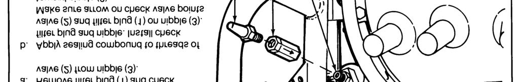
26 TROUBLESHOOTING (CONT) MALFUNCTION TEST OR INSPECTION CORRECTIVE ACTION 6. MAGNETO AIR PUMP ASSEMBLY FAILS TO PURGE SMOKE/EXHAUST GASES FROM ENGINE. WARNING A hot engine may cause fuel or trapped gases to ignite. Wait till engine cools before attempting this procedure. Make sure float bowl toggle valve is off before pulling fuel tube from metering jet. Use a suitable authorized container for draining fuel. Step 1. Test for faulty magneto-air check valve. a. b. c. d. e. f. Pull fuel tube (1) from metering jet (2) and drain fuel into container. Unscrew air pump hose (3) from flowjector (4). Remove engine head assembly (5) from engine tube (6). Disconnect ignition cable (7) from spark igniter (8). Place hand in engine tube combustion chamber, pump magneto-air pump handle (9), and check for purging air blast from pressurizing line boss (10). Replace magneto air pump check valve (p 2-22). Repeat step 1d. If no purging air blast from pressurizing line boss, go to step 2. Assemble parts in reverse order indicated on illustration. Step 2. Purging air line tube punctured or cracked. Report on DA Form 2404 to your supervisor Change 1
27 Section V. ORGANIZATIONAL MAINTENANCE PROCEDURES 2-6. INTRODUCTION. to 24 hours after operation. Use two peoa. This section contains maintenance procedures ple at nozzle end, one on each side, to lift which are the responsibility of the organizational main- and carry a hot smoke generator. tenance technician as authorized by the maintenance allocation chart (MAC) (app B) and source, mainte- b. Disassemble the smoke generator only as nance, and recoverability (SMR) coded items in the needed for repair. One quartermaster and chemical repair parts and special tools list (RPSTL) equipment repairer MOS 63J can do each task. How- (TM P). ever, it takes two people to lift and carry the smoke generator. No special environmental conditions are WARNING listed because none are required. Flames, hot gases, or hot fog oil may shoot out from smoke outlet nozzles up 2-7. SMOKE GENERATOR. p 2-8 Change
28 2-7. SMOKE GENERATOR (CONT). 2-14
29 2-15
30 2-7. SMOKE GENERATOR (CONT). 2-16
31 2-17
32 2-7. SMOKE GENERATOR (CONT). 2-18
33 p 2-15 p
34 2-7. SMOKE GENERATOR (CONT). p 2-15 p
35 p
36 2-7. SMOKE GENERATOR (CONT). p 2-15 p
37 p
38 2-7. SMOKE GENERATOR (CONT). p Change 1


39 fig D-1 p
40 2-7. SMOKE GENERATOR (CONT). 2-26
41 2-27
42 2-7. SMOKE GENERATOR (CONT). 2-28
43 2-29
44 2-7. SMOKE GENERATOR (CONT). 2-30
45 2-31
46 2-7. SMOKE GENERATOR (CONT). 2-32
47 2-33
48 2-7. SMOKE GENERATOR (CONT). 2-34
49 Change
50 2-7. SMOKE GENERATOR (CONT) Change 1
51 Change
52 2-7. SMOKE GENERATOR (CONT) Change 1
53 Change

54 2-7. SMOKE GENERATOR (CONT). p 2-51 p Change 1

55 2-8. ENGINE ASSEMBLY. fig D
56 2-8. ENGINE ASSEMBLY (CONT). fig D Change 1
57 2-9. ADJUSTABLE FLOAT ASSEMBLY. Change
58 2-9. ADJUSTABLE FLOAT ASSEMBLY (CONT) Change 1
59 Change
60 2-9. ADJUSTABLE FLOAT ASSEMBLY (CONT) Change 1
61 2-10. ENGINE HEAD ASSEMBLY. 2-47
62 2-10. ENGINE HEAD ASSEMBLY (CONT). 2-48
63 ENGINE TUBE ASSEMBLY. Change /( blank)
64

65 2-11. FUEL TANK ASSEMBLY. fig D-3 fig D
66 2-11. FUEL TANK ASSEMBLY (CONT). 2-50
67 2-12. MAGNETO AIR PUMP ASSEMBLY. p
68 2-12. MAGNETO AIR PUMP ASSEMBLY (CONT). 2-52
69 2-53
.")
70 2-12. MAGNETO AIR PUMP ASSEMBLY (CONT). p
71 2-13. IGNITION MAGNETO ASSEMBLY. p
72 2-13. IGNITION MAGNETO ASSEMBLY (CONT). 2-56
73 2-57
74 2-13. IGNITION MAGNETO ASSEMBLY (CONT). 2-58
75 2-59

76 2-14. FOG OIL INLET HOSE ASSEMBLY. p 2-25 fig D-4 fig D
77 2-15. M4 FOG OIL PUMP - EXTERNAL FlTTlNGS. Change
78 2-15. M4 FOG OIL PUMP - EXTERNAL FlTTlNGS (CONT). p
79 Change
80 2-15. M4 FOG OIL PUMP - EXTERNAL FlTTlNGS (CONT). 2-64
81 Change
.")
82 2-15. M4 FOG OIL PUMP - EXTERNAL FlTTlNGS (CONT). p 2-25 p Change 1
83 Change
84 2-15. M4 FOG OIL PUMP - EXTERNAL FlTTINGS (CONT). p 2-25 p Change 1
85 Change
86 2-15. M4 FOG OIL PUMP - EXTERNAL FITTINGS (CONT) Change 1

87 2-16. M4 FOG OIL PUMP - AIR MOTOR AND HYDRAULIC PISTONS. p 2-26 p 2-63 Change
88 2-16. M4 FOG OIL PUMP - AIR MOTOR AND HYDRAULIC PISTONS (CONT) Change 1
89 Change
. 2-66.")
90 2-16. M4 FOG OIL PUMP - AIR MOTOR AND HYDRAULIC PISTONS (CONT) Change 1
91 Change
92 2-16. M4 FOG OIL PUMP - AIR MOTOR AND HYDRAULIC PISTONS (CONT). p Change 1
93 Change
94 2-16. M4 FOG OIL PUMP - AIR MOTOR AND HYDRAULIC PISTONS (CONT) Change 1
95 p 2-64 Change
96 2-17. M4 FOG OIL PUMP - PORT PLATE AND SEPARATOR ASSEMBLIES. p

97 p p p 2-64 Change
98 2-18. M4 FOG OIL PUMP - ADJUSTMENT Change 1
99 Change
. 2-66.")
100 2-18. M4 FOG OIL PUMP - ADJUSTMENT (CONT) Change 1
101 2-19. AIR CHECK VALVE ASSEMBLY. p 2-61 Change

102 2-20. OIL DISCHARGE SEPARATOR ASSEMBLY. p Change 1
103 2-21. OIL PORT PLATE ASSEMBLY. p Change /( blank)
104
105 2-22. AIR PUMP ASSEMBLY. p 2-32 Change
106 2-22. AIR PUMP ASSEMBLY (CONT) Change 1
107 2-69

108 2-23. FRAME ASSEMBLY. fig D-5 fig D Change 1


109 2-24. IGNITION CABLE ASSEMBLY. p 2-24 fig D-8 fig D-9 Change /(2-72 blank)
110
111 CHAPTER 3 DIRECT SUPPORT MAINTENANCE INSTRUCTIONS Section I. REPAIR PARTS; SPECIAL TOOLS; TEST, MEASUREMENT, AND DIAGNOSTIC EQUIPMENT (TMDE); AND SUPPORT EQUIPMENT 3-1. COMMON TOOLS AND EQUIPMENT. For autho SPECIAL TOOLS, TMDE, AND SUPPORT rized common tools and equipment, refer to the Modi- EQUIPMENT. Refer to Maintenance Allocation Chart fied Table of Organization and Equipment (MTOE) (app B) for support equipment. assigned to your unit REPAIR PARTS. Repair parts are listed and illustrated in TM P. Section Il. DIRECT SUPPORT MAINTENANCE PROCEDURES 3-4. INTRODUCTION. a. This section contains maintenance procedures which are the responsibility of the direct support maintenance technician as authorized by the maintenance allocation chart (MAC) (app B) and source, maintenance, and recoverability (SMR) coded items in the repair parts and special tools list (RPSTL) (TM P). WARNING Flames, hot gases, or hot fog oil may shoot out from smoke outlet nozzles up to 24 hours after operation. Use two people at nozzle end, one on each side, to lift and carry a hot smoke generator. b. One quartermaster and chemical equipment repairer (MOS 63J) can do most tasks alone. However, it takes two people to lift and carry the smoke generator, engine assembly, or frame assembly. A welder is also needed, to weld the frame. No special environmental conditions are listed because none are required. 3-1

112 3-5. M3A4 SMOKE GENERATOR. 3-2
113 p 2-15 p

.")

114 3-5. M3A4 SMOKE GENERATOR (CONT). p 2-37 p 3-3 p 3-2 p 2-16 p 2-17 p 3-2 p 3-3 p
115 Change 1 3-5
116 3-5. M3A4 SMOKE GENERATOR (CONT). p 3-2 p 2-15 p 2-23 p 2-20 p
117 3-7
118 3-5. M34A4 SMOKE GENERATOR (CONT). 3-8
119 3-9
120 3-5. M3A4 SMOKE GENERATOR (CONT). p 2-34 p 2-21 p 2-23 p 2-17 p 2-23 p Change 1
121 p 2-15 p 2-23 p 2-25 p 2-26 p 3-5 p 2-32 p
122 3-6. ENGINE ASSEMBLY. fig D Change 1
123 Change
124 3-6. ENGINE ASSEMBLY (CONT). p 3-5 p 3-12 p Change 1
125 3-15
126 3-6. ENGINE ASSEMBLY (CONT). 3-16
127 3-17
. fig D-6 3-18")
128 3-6. ENGINE ASSEMBLY (CONT). fig D
129 3-19
130 3-6. ENGINE ASSEMBLY (CONT). 3-20
131 3-21

132 3-6. ENGINE ASSEMBLY (CONT). p 3-5 p 3-13 p FRONT COVER ASSEMBLY AND FRONT COVER BAFFLE. p Change 1
133 3-23
134 3-7. FRONT COVER ASSEMBLY AND FRONT COVER BAFFLE (CONT). 3-24
135 3-8. ADJUSTABLE FLOAT ASSEMBLY. p 3-12 p
136 3-8. ADJUSTABLE FLOAT ASSEMBLY (CONT). 3-26
137 3-27
138 3-8. ADJUSTABLE FLOAT ASSEMBLY (CONT) CARBURETOR RESERVOIR. p
139 3-29
140 3-9. CARBURETOR RESERVOIR (CONT). 3-30
141 3-31
142 3-9. CARBURETOR RESERVOIR (CONT). p
143 3-10. ENGINE TUBE ASSEMBLY. p
144 3-10. ENGINE TUBE ASSEMBLY (CONT). 3-34

145 3-11. FUEL TANK ASSEMBLY. p 3-4 p
146 3-11. FUEL TANK ASSEMBLY (CONT). 3-36
147 3-37
148 3-12. TOOL BOX ASSEMBLY. p
149 Change /(3-40 blank)
150
151 3-41
152 3-13. M4 FOG OIL PUMP (CONT). I 3-42
153 3-14. FRAME ASSEMBLY. p 3-11 fig D
154 3-14. FRAME ASSEMBLY (CONT). fig D
155 APPENDIX A REFERENCES A-1. TECHNICAL MANUALS. TM TM P Organizational and Direct Support Maintenance Repair Parts and Special Tools List for Generator, Smoke, Mechanical: Pulse Jet, M3A4 (NSN ) TM TM Use and Care of Hand Tools and Measuring Tools TM TM TM Operator s Manual-Generator, Smoke, Mechanical: Pulse Jet, M3A4 ( ) Operator s Manual for Welding Theory and Application Wood and Metal Repair Painting Instructions for Field Use Administrative Storage of Equipment A-2. TECHNICAL BULLETIN. TB SIG Solder and Soldering A-3. PAMPHLETS. DA PAM Military Publications: US Army Equipment lndex of Modification Work Orders DA PAM The Army Maintenance Management System (TAMMS) A-4. FIELD MANUAL. FM (TEST) First Aid for Soldiers A-5. SUPPLY CATALOGS. SC CL-A SC CL-N Shop Equipment Automotive Maintenance and Repair: Organizational Maintenance, Common No. 1, Less Power (NSN ) (LINW32593) and MAP only (NSN ) Tool Kit, General Mechanic s Automotive (NSN ) A-1
156 A-6. COMMON TABLES OF ALLOWANCES. CTA Army Medical Equipment Expendable/Durable Supplies CTA Expendable/Durable Items (Except: Medical Class V, Repair Parts and Heraldic Items) A-7. BLANK FORMS. DA Form Recommended Changes to Publications and Blank Forms DA Form Recommended Changes to Equipment Technical Publications DA Form Equipment Inspection and Maintenance Worksheet SF Report of Discrepancy (ROD) SF Quality Deficiency Report (Category 11) A-2
157 APPENDIX B MAINTENANCE ALLOCATION CHART Section I. INTRODUCTION B-1. GENERAL. a. This section provides a general explanation of all maintenance and repair functions authorized at various maintenance categories. b. The Maintenance Allocation Chart (MAC) in section II designates overall authority and responsibility for the performance of maintenance functions on the identified end item or component. The application of the maintenance functions to the end item or component will be consistent with the capacities and capabilities of the designated maintenance categories. c. Section Ill lists the tools and test equipment (both special tools and common tool sets) required for each maintenance function as referenced from section Il. d. Section IV contains supplemental instructions and explanatory notes for a particular maintenance function. B-2. MAINTENANCE FUNCTIONS. Maintenance functions will be limited to and defined as follows: a. Inspect. To determine the serviceability of an item by comparing its physical, mechanical, and/or electrical characteristics with established standards through examination (e.g., by sight, sound, or feel). b. Test. To verify serviceability by measuring the mechanical, pneumatic, hydraulic, or electrical characteristics of an item and comparing those characteristics with prescribed standards. c. Service. Operations required periodically to keep an item in proper operating condition, i.e., to clean (includes decontaminate, when required), to preserve, to drain, to paint, or to replenish fuel, lubricants, chemical fluids, or gases. d. Adjust. To maintain or regulate, within prescribed limits, by bringing into proper or exact position, or by setting the operating characteristics to specified parameters. e. Aline. To adjust specified variable elements of an item to bring about optimum or desired performance. f. Calibrate. To determine and cause corrections to be made or to be adjusted on instruments or test, measuring and diagnostic equipments used in precision measurement. Consists of comparisons of two instruments, one of which is a certified standard of known accuracy, to detect and adjust any discrepancy in the accuracy of the instrument being compared. g. Remove/Install. To remove and install the same item when required to perform service or other maintenance functions. Install may be the act of emplacing, seating, or fixing into position a spare, repair part, or module (component or assembly) in a manner to allow the proper functioning of an equipment or system. h. Replace. To remove an unserviceable item and install a serviceable counterpart in its place. Replace is authorized by the MAC and is shown as the 3d position code of the SMR code. i. Repair. The application of maintenance services 1 including fault location/troubleshooting 2, removal/installation, and disassembly/assembly 3 procedures, and maintenance actions 4 to identify troubles and restore serviceability to an item by correcting specific damage, fault, malfunction, or failure in a part, subassembly, module (component or assembly), end item, or system. 1 Services - inspect, test, service, adjust, aline, calibrate, and/or replace. 2 Fault locate/troubleshoot - The process of investigating and detecting the cause of equipment malfunctioning; the act of isolating a fault within a system or unit under test (UUT). 3 Disassemble/assemble - encompasses the step-by-step taking apart (or breakdown) of a spare/functional group coded item to the level of its least componency identified as maintenance significant (i.e., assigned as SMR code) for the category of maintenance under consideration. 4 Actions - welding, grinding, riveting, straightening, facing, remachining, and/or resurfacing. B-1
158 j. Overhaul. That maintenance effort (service/ action) prescribed to restore an item to a completely serviceable/operational condition as required by maintenance standards in appropriate technical publications (i.e., DMWR). Overhaul is normally the highest degree of maintenance performed by the Army. Overhaul does not normally return an item to like new condition. k. Rebuild. Consists of those services/actions necessary for the restoration of unserviceable equipment to a like new condition in accordance with original manufacturing standards. Rebuild is the highest degree of materiel maintenance applied to Army equipment. The rebuild operation includes the act of returning to zero those age measurements (hours/miles, etc.) considered in classifying Army equipment/components. B-3. EXPLANATION OF COLUMNS IN THE MAC, SECTION II. a. Column 1, Group Number. Column 1 lists functional group code numbers, the purpose of which is to identify maintenance significant components, assemblies, subassemblies, and modules with the next higher assembly. End item group number shall be 00. b. Column 2, Component/Assembly. Column 2 contains the names of components, assemblies, subassemblies, and modules for which maintenance is authorized. c. Column 3. Maintenance Function. Column 3 lists the functions to be performed on the item listed in column 2. (For detailed explanation of these functions, see paragraph B-2.) d. Column 4, Maintenance Category. Column 4 specifies, by the listing of a work time figure in the appropriate subcolumn(s), the category of maintenance authorized to perform the function listed in column 3. This figure represents the active time required to perform that maintenance function at the indicated category of maintenance. If the number or complexity of the tasks within the listed maintenance function vary at different maintenance categories, appropriate work time figures will be shown for each category. The work time figure represents the average time required to restore an item (assembly, subassembly, component, module, end item, or system) to a serviceable condition under typical field operating conditions. This time includes preparation time (including any necessary disassembly/ assembly time), troubleshooting/fault location time, and quality assurance/quality control time in addition to the time required to perform the specific tasks identified for the maintenance functions authorized in the maintenance allocation chart. The symbol designations for the various maintenance categories are as follows: C Operator or Crew O Organizational Maintenance F Direct Support Maintenance H General Support Maintenance L Specialized Repair Activity (SRA) 5 D Depot Maintenance e. Column 5, Tools and Equipment. Column 5 specifies, by code, those common tool sets (not individual tools) and special tools, TMDE, and support equipment required to perform the designated function. f. Column 6, Remarks. This column shall, when applicable, contain a letter code, in alphabetic order, which shall be keyed to the remarks contained in Section IV. B-4. EXPLANATION OF COLUMNS IN TOOL AND TEST EQUIPMENT REQUIREMENTS, SECTION Ill. a. Column 1, Reference Code. The tool and test equipment reference code correlates with a code used in the MAC, section 11, column 5. b. Column 2, Maintenance Category. The lowest category of maintenance authorized to use the tool or test equipment. c. Column 3, Nomenclature. Name or identification of the tool or test equipment. d. Column 4, National Stock Number. The National stock number of the tool or test equipment. e. Column 5, Tool Number. The manufacturer s part number. B-5. EXPLANATION OF COLUMNS IN REMARKS, SECTION IV. a. Column 1, Reference Code. The code recorded in column 6, Section Il. b. Column 2, Remarks. This column lists information pertinent to the maintenance function being performed as indicated in the MAC, section Il. 5 This maintenance category is not included in Section II, column (4) of the Maintenance Allocation Chart. To identify functions to this category of maintenance, enter a work time figure in the H column of Section II, column (4), and use an associated reference code in the Remarks column (6). Key the code to Section IV, Remarks, and explain the SRA complete repair application there. The explanatory remark(s) shall reference the specific Repair Parts and Special Tools List (RPSTL) TM which contains additional SRA criteria and the authorized spare/repair parts. B-2
159 Section Il. MAINTENANCE ALLOCATION CHART FOR GENERATOR, SMOKE, MECHANICAL PULSE: JET, M3A4 Change 1 B-3
160 B-4 Change 1
161 Section Ill. TOOL AND TEST EQUIPMENT REQUIREMENTS FOR GENERATOR, SMOKE, MECHANICAL: PULSE JET, M3A4 Change 1 B-5
162 Section IV. REMARKS B-6 Change 1
163 APPENDIX C EXPENDABLE/DURABLE SUPPLIES AND MATERIALS LIST Section I. INTRODUCTION C-1. SCOPE. This appendix lists expendable/durable supplies and materials you will need to operate and maintain the smoke generator. This listing is for informational purposes only and is not authority to requisition the listed items. These items are authorized to you by CTA , Expendable/Durable Items (Except Medical, Class V, Repair Parts, and Heraldic Items), or CTA 8-100, Army Medical Department Expendable/ Durable Items. C-2. EXPLANATION OF COLUMNS. a. Column (1) - Item Number. This number is assigned to the entry in the listing and is referenced in the narrative instructions to identify the material (e.g., "Use lubricating oil, item 6, app C"). b. Column (2) - Level. This column identifies the lowest level of maintenance that requires the listed item. O- Organizational Maintenance F - Direct Support Maintenance c. Column (3) - National Stock Number. This is the National stock number assigned to the item; use it to request or requisition the item. d. Column (4) - Description. Indicates the Federal item name and, if required, a description to identify the item. The last line for each item indicates the Federal Supply Code for Manufacturer (FSCM) in parentheses followed by the part number. e. Column (5) - Unit of Measure (U/M). Indicates the measure used in performing the actual maintenance function. This measure is expressed by a two-character alphabetical abbreviation (e.g., ea, in., pr). If the unit of measure differs from the unit of issue, requisition the lowest unit of issue that will satisfy your requirements. Section Il. EXPENDABLE/DURABLE SUPPLIES AND MATERIALS LIST C-1
164 C-2
165 APPENDIX D ILLUSTRATED LIST OF MANUFACTURED ITEMS D-1. INTRODUCTION. a. This appendix includes complete instructions for making items authorized to be manufactured or fabricated at organizational or direct support maintenance level. b. A part number index in alphanumeric order is provided for cross-referencing the part number of the item to be manufactured to the figure which covers fabrication criteria. c. All bulk materials needed for manufacture of an item are listed by National stock number and part number on the illustration. Item INDEX Figure Number C HOSE (Hose) D-4 D (Electrical Wire) D-8 D (Insulation Sleeving) D-9 E CHAIN (Chain) D-3 E CHAIN (Chain) D-5 E WEBBING (Strap) D-7 E (Fog Oil Exhaust Hose)..... D-1 E (Fuel Tube) D-2 E (Wire) D-6 PL (Fuel Tube) D-2 Figure D-1. Fog Oil Exhaust Hose (E ). Figure D-2. Fuel Tube (E or PL ). Change 1 D-1
166 Figure D-3. Chain (E CHAIN). Figure D-4. Hose (C HOSE). Figure D-5. Chain (E CHAIN). D-2
.")
167 Figure D-6. Wire (E ). Figure D-7. Strap (E WEBBING). Change 1 D-3
.")
168 Figure D-8. Electrical Wire (D ). Figure D-9. Insulation Sleeving (D ). D-4 Change 1
169 ALPHABETICAL INDEX Subject Page Subject Page A Accumulator assembly Installation Removal Troubleshooting Adjustable float assembly Installation Removal Repair Air check valve assembly Installation Principles of operation Removal Repair Troubleshooting Air pump assembly Installation Preventive maintenance checks and services (PMCS) Principles of operation Removal Repair Alphabetical index lndex-1 Blank forms A-2 Carburetor reservoir Installation Removal Repair Common tables of allowances A-2 Common tools and equipment ; 3-1 Destruction of Army materiel to prevent enemy use Direct support maintenance instructions Maintenance procedures Repair parts; special tools; test, measurement, and diagnostic equipment (TMDE); and support equipment B C D E Engine assembly Installation Principles of operation Removal Repair Engine head assembly Disassembly Principles of operation Reassembly Repair Engine tube assembly Disassembly Reassembly Repair Replacement of engine head gasket Equipment Data Description lmprovement recommendations (EIR) Expendable/durable supplies and materials list (E/DSML) C-1 Field manuals A-1 Fog oil inlet hose Disassembly Installation Reassembly Removal Repair Fog oil pump, M4 Adjustment Installation Principles of operation Removal Repair ; ; Frame assembly Installation Removal Repair Front cover assembly Installation Removal Repair F Change 1 Index 1
170 Subject Page Subject Page F Front cover baffle Installation Removal Repair Fuel tank assembly Installation Principles of operation Removal Repair ; 3-4 General information How-to-use this manual ii Ignition cable Repair Troubleshooting Ignition magneto assembly Installation Removal Repair Troubleshooting Illustrated list of manufactured items D-1 Improvement recommendations (EIR), reporting equipment Introduction Magneto-air pump assembly Disassembly Installation Preventive maintenance checks and services (PMCS) Pnnciples of operation Reassembly Removal Repair Troubleshooting Maintenance Allocation chart B-1 Direct support Forms, records, and reports Organizational G H I M Manufactured items illustrations D-1 Manufactured items part number index... D-1 Model number and equipment name Oil Discharge Separator Assembly Oil Port Plate Assembly Official nomenclature, names, and designations Organizational maintenance instructions Maintenance procedures Preventive maintenance checks and services (PMCS) Troubleshooting Pamphlets A-1 Preventive maintenance checks and services (PMCS), organizational Principles of operation Reporting equipment improvement recommendations (EIR) O P R Scope Service upon receipt of smoke generator Smoke generator Data Inspection Maintenance allocation chart (MAC).... B-1 Operational test Painting Principles of operation Repair Servicing Special tools, TMDE, and support equipment Supply bulletin A-1 Supply catalogs A-1 Table of contents i Technical bulletins A-1 Technical manuals A-1 S T Index 2 Change 1 U.S. GOVERNMENT PRINTING OFFICE: /00242 PIN:
171 Subject Page Subject Page Tool box assembly Disassembly Installation Reassembly Removal Repair Tools and test equipment requirements ; 3-1 Troubleshooting organizational maintenance Symptom index Type of manual Index 3/(Index 4 blank)
172
173
174
175
176
177
178

179
180
181 By Order of the Secretary of the Army: JOHN A. WICKHAM, JR. General, United States Army Chief of Staff Official: DONALD J. DELANDRO Brigadier General, United States Army The Adjutant General Distribution: To be distributed in accordance with DA Form 12-28, Organizational and Direct Support requirements for Mechanical Smoke Generators. *U.S. GOVERNMENT PRINTING OFFICE: :20020
182
183
184 058818

185 This fine document... Was brought to you by me: Liberated Manuals -- free army and government manuals Why do I do it? I am tired of sleazy CD-ROM sellers, who take publicly available information, slap watermarks and other junk on it, and sell it. Those masters of search engine manipulation make sure that their sites that sell free information, come up first in search engines. They did not create it... They did not even scan it... Why should they get your money? Why are not letting you give those free manuals to your friends? I am setting this document FREE. This document was made by the US Government and is NOT protected by Copyright. Feel free to share, republish, sell and so on. I am not asking you for donations, fees or handouts. If you can, please provide a link to liberatedmanuals.com, so that free manuals come up first in search engines: <A HREF= Military and Government Manuals</A> Sincerely Igor Chudov
THIS MANUAL SUPERSEDES TM DATED 30 MAY 1994, INCLUDING ALL CHANGES. TECHNICAL MANUAL
 THIS MANUAL SUPERSEDES TM 9-2330-385-14 DATED 30 MAY 1994, INCLUDING ALL CHANGES. TECHNICAL MANUAL OPERATOR S, UNIT, DIRECT SUPPORT AND GENERAL SUPPORT MAINTENANCE MANUAL INTRODUCTION 1-1 OPERATING INSTRUCTIONS
FILTER/ SEPARATOR, LIQUID FUEL 15 GPM, ALUMINUM, SKID MOUNTED (NSN )
") *TM 10 4330 230-12&P TECHNICAL MANUAL OPERATOR S AND UNIT MAINTENANCE MANUAL (INCLUDING REPAIR PARTS AND SPECIAL TOOLS LIST) FOR FILTER/ SEPARATOR, LIQUID FUEL 15 GPM, ALUMINUM, SKID MOUNTED (NSN 4330-00-438-1460)
*TM 10 4330 230-12&P TECHNICAL MANUAL OPERATOR S AND UNIT MAINTENANCE MANUAL (INCLUDING REPAIR PARTS AND SPECIAL TOOLS LIST) FOR FILTER/ SEPARATOR, LIQUID FUEL 15 GPM, ALUMINUM, SKID MOUNTED (NSN 4330-00-438-1460)
TM TECHNICAL MANUAL UNIT, INTERMEDIATE DIRECT SUPPORT AND INTERMEDIATE GENERAL SUPPORT MAINTENANCE INSTRUCTIONS
 TECHNICAL MANUAL UNIT, INTERMEDIATE DIRECT SUPPORT AND INTERMEDIATE GENERAL SUPPORT MAINTENANCE INSTRUCTIONS MAIN REDUCTION GEAR FOR LANDING CRAFT UTILITY (LCU) NSN 1905-01-154-1191 INTRODUCTION 1-1 UNIT
EMERGENCY GENERATOR SET
 TECHNICAL MANUAL UNIT, INTERMEDIATE DIRECT SUPPORT AND INTERMEDIATE GENERAL SUPPORT MAINTENANCE INSTRUCTIONS EMERGENCY GENERATOR SET FOR LANDING CRAFT UTILITY (LCU) NSN 1905-01-154-1191 INTRODUCTION 1-1
UNIT MAINTENANCE INSTRUCTIONS PAGE 2-1 DIRECT SUPPORT
 TECHNICAL MANUAL TABLE OF CONTENTS PAGE i INTRODUCTION PAGE 1-1 UNIT, DIRECT SUPPORT AND GENERAL SUPPORT MAINTENANCE MANUAL UNIT MAINTENANCE INSTRUCTIONS PAGE 2-1 DIRECT SUPPORT MAINTENANCE INSTRUCTIONS
TECHNICAL MANUAL OPERATOR, AVIATION UNIT, AND AVIATION INTERMEDIATE MAINTENANCE MANUAL WITH REPAIR PARTS AND SPECIAL TOOLS LIST CHAPTER 1 INTRODUCTION
 EXTENDED RANGE FUEL SYSTEM ARMY MODEL CH-47 HELICOPTER TECHNICAL MANUAL OPERATOR, AVIATION UNIT, AND AVIATION INTERMEDIATE MAINTENANCE MANUAL WITH REPAIR PARTS AND SPECIAL TOOLS LIST CHAPTER 1 INTRODUCTION
TM P Supersedes copy dated May 1974 TECHNICAL MANUAL DIRECT SUPPORT AND GENERAL SUPPORT MAINTENANCE REPAIR PARTS AND SPECIAL TOOLS LISTS
 Supersedes copy dated May 1974 TECHNICAL MANUAL REPAIR PARTS AND SPECIAL TOOLS LISTS FOR ENGINE, DIESEL (MULTIFUEL): TURBOCHARGED, FUEL INJECTED, WATER COOLED, 6-CYLINDER ASSEMBLY (MILITARY MODELS LDT-465-1D,
TECHNICAL MANUAL OPERATOR S, UNIT, DIRECT SUPPORT, AND GENERAL SUPPORT MAINTENANCE MANUAL FOR
 TECHNICAL MANUAL OPERATOR S, UNIT, DIRECT SUPPORT, AND GENERAL SUPPORT MAINTENANCE MANUAL FOR SEMITRAILER, TANK: 5000 GALLON, (POTABLE WATER DISPENSING) XM1098 (NSN 2330-01-330-2779) Approved for public
TECHNICAL MANUAL OPERATOR S, ORGANIZATIONAL AND DIRECT SUPPORT MAINTENANCE MANUAL TANK AND PUMP UNIT, LIQUID DISPENSING
 TECHNICAL MANUAL OPERATOR S, ORGANIZATIONAL AND DIRECT SUPPORT MAINTENANCE MANUAL TANK AND PUMP UNIT, LIQUID DISPENSING FOR TRUCK MOUNTING (UNITED MANUFACTURING AND ENGINEERING CORP. MODEL STYLE 1) NSN
TECHNICAL MANUAL OPERATOR'S, UNIT, DIRECT SUPPORT, AND GENERAL SUPPORT MAINTENANCE MANUAL (INCLUDING REPAIR PARTS AND SPECIAL TOOLS LISTS) FOR
 FOR") TECHNICAL MANUAL OPERATOR'S, UNIT, DIRECT SUPPORT, AND GENERAL SUPPORT MAINTENANCE MANUAL (INCLUDING REPAIR PARTS AND SPECIAL TOOLS LISTS) Operating Instructions 2-1 FOR DISTRIBUTOR, WATER, SEMITRAILER
TECHNICAL MANUAL OPERATOR'S, UNIT, DIRECT SUPPORT, AND GENERAL SUPPORT MAINTENANCE MANUAL (INCLUDING REPAIR PARTS AND SPECIAL TOOLS LISTS) Operating Instructions 2-1 FOR DISTRIBUTOR, WATER, SEMITRAILER
TM &P TECHNICAL MANUAL
 TECHNICAL MANUAL TM 9-2330-376-14&P OPERATOR S, ORGANIZATIONAL, DIRECT SUPPORT AND GENERAL SUPPORT MAINTENANCE MANUAL (INCLUDING REPAIR PARTS AND SPECIAL TOOLS LISTS) FOR CHASSIS, TRAILER: 5-TON, 4-WHEEL,
UNIT MAINTENANCE MANUAL INCLUDING REPAIR PARTS AND SPECIAL TOOLS LIST MOUNTING KIT, SMOKE GENERATOR: M288 ( )
") UNIT MAINTENANCE MANUAL INCLUDING REPAIR PARTS AND SPECIAL TOOLS LIST MOUNTING KIT, SMOKE GENERATOR: M288 (1040-01-248-6985) DISTRIBUTION STATEMENT A. Approved for public release; distribution is unlimited.
UNIT MAINTENANCE MANUAL INCLUDING REPAIR PARTS AND SPECIAL TOOLS LIST MOUNTING KIT, SMOKE GENERATOR: M288 (1040-01-248-6985) DISTRIBUTION STATEMENT A. Approved for public release; distribution is unlimited.
HEADQUARTERS, DEPARTMENT OF THE ARMY
 TECHNICAL MANUAL OPERATOR'S, UNIT AND DIRECT SUPPORT MAINTENANCE MANUAL INCLUDING REPAIR PARTS AND SPECIAL TOOLS LIST EQUIPMENT DESCRIPTION 1-3 PRINCIPLES OF OPERATION 1-6 DESCRIPTION AND USE OF OPERATOR'S
TECHNICAL MANUAL DIRECT SUPPORT AND GENERAL SUPPORT MAINTENANCE REPAIR PARTS AND SPECIAL TOOLS LIST (INCLUDING DEPOT MAINTENANCE REPAIR PARTS)
") TECHNICAL MANUAL DIRECT SUPPORT AND GENERAL SUPPORT MAINTENANCE REPAIR PARTS AND SPECIAL TOOLS LIST (INCLUDING DEPOT MAINTENANCE REPAIR PARTS) ENGINE W/CONTAINER: MODEL 5063-5299 (2815-00-124-5390) (2815-01-295-7458)
TECHNICAL MANUAL DIRECT SUPPORT AND GENERAL SUPPORT MAINTENANCE REPAIR PARTS AND SPECIAL TOOLS LIST (INCLUDING DEPOT MAINTENANCE REPAIR PARTS) ENGINE W/CONTAINER: MODEL 5063-5299 (2815-00-124-5390) (2815-01-295-7458)
CLEANER, STEAM, HIGH PRESSURE, HOT AND COLD WATER JET, TRAILER MOUNTED ( )(EIC: 2BC)
(EIC: 2BC)") TECHNICAL MANUAL TM 9-4940-531-24P UNIT, DIRECT SUPPORT, AND GENERAL SUPPORT MAINTENANCE FOR CLEANER, STEAM, HIGH PRESSURE, HOT AND COLD WATER JET, TRAILER MOUNTED (4940-01-025-9856)(EIC: 2BC) DISTRIBUTION
TECHNICAL MANUAL TM 9-4940-531-24P UNIT, DIRECT SUPPORT, AND GENERAL SUPPORT MAINTENANCE FOR CLEANER, STEAM, HIGH PRESSURE, HOT AND COLD WATER JET, TRAILER MOUNTED (4940-01-025-9856)(EIC: 2BC) DISTRIBUTION
TECHNICAL MANUAL OPERATOR'S, UNIT, DIRECT SUPPORT AND GENERAL SUPPORT MAINTENANCE MANUAL (INCLUDING REPAIR PARTS AND SPECIAL TOOLS LIST)
") TECHNICAL MANUAL OPERATOR'S, UNIT, DIRECT SUPPORT AND GENERAL SUPPORT MAINTENANCE MANUAL (INCLUDING REPAIR PARTS AND SPECIAL TOOLS LIST) INTRODUCTION 1-1 OPERATING INSTRUCTIONS 2-1 OPERATOR MAINTENANCE
TECHNICAL MANUAL OPERATOR'S, UNIT, DIRECT SUPPORT AND GENERAL SUPPORT MAINTENANCE MANUAL (INCLUDING REPAIR PARTS AND SPECIAL TOOLS LIST) INTRODUCTION 1-1 OPERATING INSTRUCTIONS 2-1 OPERATOR MAINTENANCE
TECHNICAL MANUAL M149A2. This manual supersedes TM &P, dated February 1981, and all changes.
 TECHNICAL MANUAL TM 9-2330-267-14&P OPERATOR S, ORGANIZATIONAL, DIRECT SUPPORT, AND GENERAL SUPPORT MAINTENANCE MANUAL (INCLUDING REPAIR PARTS AND SPECIAL TOOLS LISTS) FOR TRAILER, TANK, WATER: 400 GALLON,
TECHNICAL MANUAL ORGANIZATIONAL MAINTENANCE MANUAL VOLUME 1 OF 3
 TECHNICAL MANUAL ORGANIZATIONAL MAINTENANCE MANUAL VOLUME 1 OF 3 This copy is a reprint which includes current pages from Change 1. TRACTOR, WHEELED (DED) LOADER BACKHOE W/HYDRAULIC IMPACT TOOL AND WIHYDRAULIC
TECHNICAL MANUAL ORGANIZATIONAL, DIRECT SUPPORT, AND GENERAL SUPPORT MAINTENANCE MANUAL WITH REPAIR PARTS AND SPECIAL TOOLS LIST
 TECHNICAL MANUAL ORGANIZATIONAL, DIRECT SUPPORT, AND GENERAL SUPPORT MAINTENANCE MANUAL WITH REPAIR PARTS AND SPECIAL TOOLS LIST BITUMINOUS DISTRIBUTOR BODY M918, MODEL D-63 NSN 3895-01-028-4390 E.D. ETNYRE
TM THIS MANUAL SUPERSEDES TM DATED 25 FEB 1994, INCLUDING ALL CHANGES.
 THIS MANUAL SUPERSEDES TM 9-2320-364-10 DATED 25 FEB 1994, INCLUDING ALL CHANGES. OPERATOR S MANUAL HOW TO USE THIS MANUAL iii EQUIPMENT DESCRIPTION 1-9 OPERATOR S CONTROLS AND INDICATORS 2-3 PREVENTIVE
TECHNICAL MANUAL CHASSIS, TRAILER: GENERAL PURPOSE, 3-1/2 TON, 2-WHEEL, M353 (NSN )
") TECHNICAL MANUAL OPERATOR S, ORGANIZATIONAL, DIRECT SUPPORT, AND GENERAL SUPPORT MAINTENANCE MANUAL (INCLUDING REPAIR PARTS AND SPECIAL TOOLS LISTS) FOR CHASSIS, TRAILER: GENERAL PURPOSE, 3-1/2 TON, 2-WHEEL,
TECHNICAL MANUAL OPERATOR S, ORGANIZATIONAL, DIRECT SUPPORT, AND GENERAL SUPPORT MAINTENANCE MANUAL (INCLUDING REPAIR PARTS AND SPECIAL TOOLS LISTS) FOR CHASSIS, TRAILER: GENERAL PURPOSE, 3-1/2 TON, 2-WHEEL,
TECHNICAL MANUAL. Operator's, Organizational and Direct Support Maintenance Manual (Including Repair Parts and Special Tools List) for
 for") TECHNICAL MANUAL Operator's, Organizational and Direct Support Maintenance Manual (Including Repair Parts and Special Tools List) for CONVERTER ASSEMBLY, VAPOR RECOVERY PART NUMBER F428A NSN 2590-01-090-7659
TECHNICAL MANUAL Operator's, Organizational and Direct Support Maintenance Manual (Including Repair Parts and Special Tools List) for CONVERTER ASSEMBLY, VAPOR RECOVERY PART NUMBER F428A NSN 2590-01-090-7659
MAIN PROPULSION ENGINE INTERMEDIATE GENERAL FOR MAINTENANCE INSTRUCTIONS 3-1 LANDING CRAFT UTILITY (LCU) INDEX-1
 INDEX-1") TECHNICAL MANUAL UNIT, INTERMEDIATE DIRECT INTRODUCTION 1-1 SUPPORT AND INTERMEDIATE GENERAL SUPPORT UNIT MAINTENANCE 2-1 MAINTENANCE INSTRUCTIONS INSTRUCTIONS MAIN PROPULSION ENGINE INTERMEDIATE GENERAL
TECHNICAL MANUAL UNIT, INTERMEDIATE DIRECT INTRODUCTION 1-1 SUPPORT AND INTERMEDIATE GENERAL SUPPORT UNIT MAINTENANCE 2-1 MAINTENANCE INSTRUCTIONS INSTRUCTIONS MAIN PROPULSION ENGINE INTERMEDIATE GENERAL
TM T.O. 38G
 T.O. 38G1-48-12-2-1 TECHNICAL MANUAL VOLUME 2 OF 2 PART 1 OF 2 MAINTENANCE DIRECT SUPPORT AND GENERAL SUPPORT LEVEL ENGINE ASSEMBLY, DIESEL (MULTIFUEL): NATURALLY ASPIRATED OR TURBOCHARGED, FUEL-INJECTED,
TECHNICAL MANUAL UNIT, DIRECT SUPPORT AND GENERAL SUPPORT MAINTENANCE INSTRUCTIONS
 TECHNICAL MANUAL UNIT, DIRECT SUPPORT AND GENERAL SUPPORT MAINTENANCE INSTRUCTIONS DIESEL ENGINE MODEL 4039T 4 CYLINDER 3.9 LITER NSN: 2815-01-350-2208 This copy is a reprint which includes current pages
TECHNICAL MANUAL UNIT, DIRECT SUPPORT, AND GENERAL SUPPORT MAINTENANCE REPAIR PARTS AND SPECIAL TOOLS LISTS FOR
 TECHNICAL MANUAL UNIT, DIRECT SUPPORT, AND GENERAL SUPPORT MAINTENANCE REPAIR PARTS AND SPECIAL TOOLS LISTS FOR BULK HAUL, SELF LOAD/UNLOAD M967 (NSN 2330-01 -050-5632) AND M967A1 (NSN 2330-01-1 55-0046)
TECHNICAL MANUAL OPERATOR'S, ORGANIZATIONAL, DIRECT SUPPORT AND GENERAL SUPPORT MAINTENANCE MANUAL
 TECHNICAL MANUAL OPERATOR'S, ORGANIZATIONAL, DIRECT SUPPORT AND GENERAL SUPPORT MAINTENANCE MANUAL COMPRESSOR, ROTARY; AIR, SKID MOUNTED; DIESEL ENGINE DRIVEN, 125 CFM, 100 PSIG (DAVEY MODEL 6M125) NSN
1 1/2-TON, 2-WHEEL, M332 PAGE B1 (NSN ) REPAIR PARTS AND SPECIAL TOOLS LIST PAGE F-1
 REPAIR PARTS AND SPECIAL TOOLS LIST PAGE F-1") TECHNICAL MANUAL OPERATOR'S, ORGANIZATIONAL, DIRECT SUPPORT, AND GENERAL SUPPORT MAINTENANCE (INCLUDING REPAIR PARTS AND SPECIAL TOOLS LIST) OPERATING INSTRUCTIONS PAGE 2-1 OPERATOR PMCS PAGE 2-4 OPERATOR
TECHNICAL MANUAL OPERATOR'S, ORGANIZATIONAL, DIRECT SUPPORT, AND GENERAL SUPPORT MAINTENANCE (INCLUDING REPAIR PARTS AND SPECIAL TOOLS LIST) OPERATING INSTRUCTIONS PAGE 2-1 OPERATOR PMCS PAGE 2-4 OPERATOR
ARMY TM &P AIR FORCE TO 36A
 ARMY TM 9-2330-213-14&P AIR FORCE TO 36A11-1-461 TECHNICAL MANUAL OPERATOR S, UNIT, DIRECT SUPPORT, AND GENERAL SUPPORT MAINTENANCE MANUAL (INCLUDING REPAIR PARTS AND SPECIAL TOOLS LISTS) FOR TRAILER,
TECHNICAL MANUAL UNIT, DIRECT SUPPORT AND GENERAL SUPPORT MAINTENANCE REPAIR PARTS AND SPECIAL TOOLS LIST
 *TM 10-4320-343-24P UNIT, DIRECT SUPPORT AND GENERAL SUPPORT MAINTENANCE REPAIR PARTS AND SPECIAL TOOLS LIST WHEEL MOUNTED, 350 GALLONS PER MINUTE (GPM) 275 FOOT HEAD, MODELS: 350 PAF (NSN 4320-01-092-3551)
TECHNICAL MANUAL AVIATION UNIT AND AVIATION INTERMEDIATE MAINTENANCE MANUAL ENGINE, GAS TURBINE MODEL T55-L-714 NSN
 TECHNICAL MANUAL AVIATION UNIT AND AVIATION INTERMEDIATE MAINTENANCE MANUAL ENGINE, GAS TURBINE MODEL T55-L-714 NSN 2840-01-353-7635 DISTRIBUTION STATEMENT A: Approved for public release; distribution
TECHNICAL MANUAL OPERATOR'S AND UNIT MAINTENANCE MANUAL (INCLUDING REPAIR PARTS AND SPECIAL TOOLS LIST)
") *TM 10-4330-232-12&P TECHNICAL MANUAL OPERATOR'S AND UNIT MAINTENANCE MANUAL (INCLUDING REPAIR PARTS AND SPECIAL TOOLS LIST) FILTER/SEPARATOR, LIQUID FUEL, TYPE I FRAME MOUNTED, 50 GPM CAPACITY (MODEL
*TM 10-4330-232-12&P TECHNICAL MANUAL OPERATOR'S AND UNIT MAINTENANCE MANUAL (INCLUDING REPAIR PARTS AND SPECIAL TOOLS LIST) FILTER/SEPARATOR, LIQUID FUEL, TYPE I FRAME MOUNTED, 50 GPM CAPACITY (MODEL
TECHNICAL MANUAL UNIT, DIRECT SUPPORT, AND GENERAL SUPPORT MAINTENANCE REPAIR PARTS AND SPECIAL TOOLS LIST
 TM 10-3930-671-24P TECHNICAL MANUAL UNIT, DIRECT SUPPORT, AND GENERAL SUPPORT MAINTENANCE REPAIR PARTS AND SPECIAL TOOLS LIST TRUCK, FORKLIFT, CLEAN BURN DIESEL, FRONT-LOADING, 4000 LB. CAPACITY, M483
TM PALLETIZED LOAD SYSTEM DIRECT SUPPORT AND GENERAL SUPPORT MAINTENANCE VOLUME I MODEL M1074/M1075
 THIS MANUAL SUPERSEDES DATED 25 FEB 1994, INCLUDING ALL CHANGES. TECHNICAL MANUAL DIRECT SUPPORT AND GENERAL SUPPORT MAINTENANCE VOLUME I INTRODUCTION 1-1 VEHICLE MAINTENANCE 2-1 ENGINE TROUBLESHOOTING
DEPARTMENT OF THE ARMY TECHNICAL MANUAL OPERATOR S, UNIT, INTERMEDIATE DIRECT SUPPORT AND INTERMEDIATE GENERAL SUPPORT MAINTENANCE
 TM 9-2330-380-14 & P DEPARTMENT OF THE ARMY TECHNICAL MANUAL OPERATOR S, UNIT, INTERMEDIATE DIRECT SUPPORT AND INTERMEDIATE GENERAL SUPPORT MAINTENANCE (INCLUDING REPAIR PARTS AND SPECIAL TOOLS LISTS)
COMPRESSOR UNIT, ROTARY: AIR, TRAILER MOUNTED, 250 CFM P-250-WDM-H268 (NSN )
") ARMY TM 5-4310-452-24P MARINE CORPS TM 08917A-24P TECHNICAL MANUAL UNIT, DIRECT SUPPORT AND GENERAL SUPPORT MAINTENANCE REPAIR PARTS AND SPECIAL TOOLS LISTS (INCLUDING DEPOT MAINTENANCE REPAIR PARTS AND
ARMY TM 5-4310-452-24P MARINE CORPS TM 08917A-24P TECHNICAL MANUAL UNIT, DIRECT SUPPORT AND GENERAL SUPPORT MAINTENANCE REPAIR PARTS AND SPECIAL TOOLS LISTS (INCLUDING DEPOT MAINTENANCE REPAIR PARTS AND
ARMY TM MARINE CORPS TM 09295A-14/1 TECHNICAL MANUAL
 ARMY TM 9-2330-381-14 MARINE CORPS TM 09295A-14/1 TECHNICAL MANUAL OPERATOR'S, UNIT, DIRECT SUPPORT, AND GENERAL SUPPORT MAINTENANCE MANUAL FOR HEAVY EQUIPMENT TRANSPORTER SEMITRAILER 70 TON, M1000 NSN
TM TECHNICAL MANUAL
 TECHNICAL MANUAL AVIATION UNIT AND AVIATION INTERMEDIATE MAINTENANCE MANUAL ENGINE ASSEMBLY MODE L T63-A-5A NSN 2840-00-923-6023 MODEL T63-A-700 NSN 2840-00-179-5536 HEADQUARTERS DEPARTMENT OF THE ARMY
OPERATOR S, UNIT, DIRECT SUPPORT AND GENERAL SUPPORT MAINTENANCE MANUAL FOR ADVANCED AVIATION FORWARD AREA REFUELING SYSTEM (AAFARS) MODEL M100A1
 MODEL M100A1") TECHNICAL MANUAL OPERATOR S, UNIT, DIRECT SUPPORT AND GENERAL SUPPORT MAINTENANCE MANUAL FOR ADVANCED AVIATION FORWARD AREA REFUELING SYSTEM (AAFARS) MODEL M100A1 NSN 4930-01-495-0024 DISTRIBUTION STATEMENT
TECHNICAL MANUAL OPERATOR S, UNIT, DIRECT SUPPORT AND GENERAL SUPPORT MAINTENANCE MANUAL FOR ADVANCED AVIATION FORWARD AREA REFUELING SYSTEM (AAFARS) MODEL M100A1 NSN 4930-01-495-0024 DISTRIBUTION STATEMENT
SAW, CONCRETE, SELF PROPELLED, ABRASIVE DISK, MODEL C NSN
 TECHNICAL MANUAL UNIT, DIRECT SUPPORT AND GENERAL SUPPORT MAINTENANCE REPAIR PARTS AND SPECIAL TOOLS LIST FOR SAW, CONCRETE, SELF PROPELLED, ABRASIVE DISK, MODEL C-3000-30 NSN 3895-01-303-8909 Approved
DEPARTMENT OF THE ARMY TECHNICAL MANUAL OPERATOR AND ORGANIZATIONAL MAINTENANCE MANUAL (INCLUDING REPAIR PARTS AND SPECIAL TOOLS LIST) FOR
 FOR") TM 9-4910-389-12 DEPARTMENT OF THE ARMY TECHNICAL MANUAL OPERATOR AND ORGANIZATIONAL MAINTENANCE MANUAL (INCLUDING REPAIR PARTS AND SPECIAL TOOLS LIST) FOR CLEANER AND TESTER, SPARK PLUG: BENCH MOUNTED
TM 9-4910-389-12 DEPARTMENT OF THE ARMY TECHNICAL MANUAL OPERATOR AND ORGANIZATIONAL MAINTENANCE MANUAL (INCLUDING REPAIR PARTS AND SPECIAL TOOLS LIST) FOR CLEANER AND TESTER, SPARK PLUG: BENCH MOUNTED
TECHNICAL MANUAL AVIATION UNIT AND AVIATION INTERMEDIATE MAINTENANCE MANUAL ENGINE, GAS TURBINE MODEL T55-L-714 NSN
 TM 1-2840-252-23--2 TECHNICAL MANUAL AVIATION UNIT AND AVIATION INTERMEDIATE MAINTENANCE MANUAL ENGINE, GAS TURBINE MODEL T55-L-714 NSN 2840-01-353-7635 DISTRIBUTION STATEMENT A: Approved for public release,
TECHNICAL MANUAL UNIT MAINTENANCE MANUAL FOR TRUCK, TRACTOR, LINE HAUL 52,000 GVWR, 6 X 4, M915A2 (NSN )
") TECHNICAL MANUAL TM 9-2320-363-20-1 VOLUME NO. 1 UNIT MAINTENANCE MANUAL FOR TRUCK, TRACTOR, LINE HAUL 52,000 GVWR, 6 X 4, M915A2 (NSN 2320-01-272-5029) I TABLE I HOW OF CONTENTS TO USE THIS MANUAL I iii
TECHNICAL MANUAL TM 9-2320-363-20-1 VOLUME NO. 1 UNIT MAINTENANCE MANUAL FOR TRUCK, TRACTOR, LINE HAUL 52,000 GVWR, 6 X 4, M915A2 (NSN 2320-01-272-5029) I TABLE I HOW OF CONTENTS TO USE THIS MANUAL I iii
TM DIRECT SUPPORT AND GENERAL SUPPORT MAINTENANCE MANUAL FOR. HEADQUARTERS, DEPARTMENT OF THE ARMY August 1978 Change 2
 DIRECT SUPPORT AND GENERAL SUPPORT MAINTENANCE MANUAL FOR HULL, SUSPENSION, AND MISCELLANEOUS HULL COMPONENTS OF THE ARMORED RECONNAISSANCE/AIRBORNE ASSAULT VEHICLE: FULL-TRACKED, 152-MM GUN/LAUNCHER M551A1
TECHNICAL MANUAL UNIT, DIRECT SUPPORT AND GENERAL SUPPORT MAINTENANCE REPAIR PARTS AND SPECIAL TOOLS LIST
 *TM 5-4930-28-24P TECHNICAL MANUAL UNIT, DIRECT SUPPORT AND GENERAL SUPPORT MAINTENANCE REPAIR PARTS AND SPECIAL TOOLS LIST (INCLUDING DEPOT MAINTENANCE REPAIR PARTS AND SPECIAL TOOLS) LUBRICATING AND
TECHNICAL MANUAL. SUPERSESSION NOTICE: This manual supersedes the repair parts section only for TM &P dated 8 January 1988
 TECHNICAL MANUAL UNIT,DIRECT SUPPORT, AND GENERAL SUPPORT MAINTENANCE REPAIR PARTS AND SPECIAL TOOLS LISTS (INCLUDING DEPOT MAINTENANCE REPAIR PARTS LISTS AND SPECIAL TOOL LISTS) TRUCK, FORK LIFT, CLEAN
OPERATOR S, UNIT, DIRECT SUPPORT AND GENERAL SUPPORTMAINTENANCE MANUAL INCLUDING REPAIR PARTS AND SPECIAL TOOLS LISTS FOR ( )
") OPERATOR S, UNIT, DIRECT SUPPORT AND GENERAL SUPPORTMAINTENANCE MANUAL INCLUDING REPAIR PARTS AND SPECIAL TOOLS LISTS FOR SEMITRAILER, TANK, FUEL, 7500 GALLON, (2330-01-275-7475) M1062 Fruehauf Corporation
OPERATOR S, UNIT, DIRECT SUPPORT AND GENERAL SUPPORTMAINTENANCE MANUAL INCLUDING REPAIR PARTS AND SPECIAL TOOLS LISTS FOR SEMITRAILER, TANK, FUEL, 7500 GALLON, (2330-01-275-7475) M1062 Fruehauf Corporation
TM &P TECHNICAL MANUAL
 TECHNICAL MANUAL OPERATOR S, ORGANIZATIONAL, DIRECT SUPPORT, AND GENERAL SUPPORT MAINTENANCE MANUAL (INCLUDING REPAIR PARTS AND SPECIAL TOOLS LISTS) FOR TM 9-2330-359-14&P SEMITRAILER, FLATBED: BREAKBULK/CONTAINER
TECHNICAL MANUAL UNIT AND DIRECT SUPPORT MAINTENANCE REPAIR PARTS AND SPECIAL TOOLS LIST (INCLUDING DEPOT MAINTENANCE REPAIR PARTS AND SPECIAL TOOLS)
") *TM 10-4610-234-23P UNIT AND DIRECT SUPPORT MAINTENANCE REPAIR PARTS AND SPECIAL TOOLS LIST (INCLUDING DEPOT MAINTENANCE REPAIR PARTS AND SPECIAL TOOLS) 40, 000 GALLON WATER STORAGE AND DISTRIBUTION SYSTEM
*TM 10-4610-234-23P UNIT AND DIRECT SUPPORT MAINTENANCE REPAIR PARTS AND SPECIAL TOOLS LIST (INCLUDING DEPOT MAINTENANCE REPAIR PARTS AND SPECIAL TOOLS) 40, 000 GALLON WATER STORAGE AND DISTRIBUTION SYSTEM
TESTER, DIESEL INJECTOR NOZZLE MODEL DT-1300/7008 (KIENE DIESEL ACCESSORIES, INC.) (NSN )
 (NSN )") TM 9-90-623-&P TECHNICAL MANUAL OPERATOR S ORGANIZATIONAL, DIRECT SUPPORT AND GENERAL SUPPORT MAINTENANCE MANUAL INCLUDING REPAIR PARTS LIST TESTER, DIESEL INJECTOR NOZZLE MODEL DT-300/7008 (KIENE DIESEL
TM 9-90-623-&P TECHNICAL MANUAL OPERATOR S ORGANIZATIONAL, DIRECT SUPPORT AND GENERAL SUPPORT MAINTENANCE MANUAL INCLUDING REPAIR PARTS LIST TESTER, DIESEL INJECTOR NOZZLE MODEL DT-300/7008 (KIENE DIESEL
TECHNICAL MANUAL UNIT, DIRECT SUPPORT, AND GENERAL SUPPORT MAINTENANCE REPAIR PARTS AND SPECIAL TOOLS LISTS
 TECHNICAL MANUAL UNIT, DIRECT SUPPORT, AND GENERAL SUPPORT MAINTENANCE REPAIR PARTS AND SPECIAL TOOLS LISTS TRUCK, FORK LIFT, GASOLINE ENGINE DRIVEN, SOLID RUBBER TIRES, 4,000 LB CAPACITY ARMY MODEL MHE-203
HEADQUARTERS, DEPARTMENT OF THE ARMY
 CHECK FOR CURRENT CHANGES TECHNICAL MANUAL SUPERSEDES COPY DIRECT SUPPORT MAINTENANCE MANUAL DATED 10 JUNE 1974 INCLUDING REPAIR PARTS AND SPECIAL TOOLS LIST SEE PAGE i FOR DETAILS (INCLUDING DEPOT MAINTENANCE
TM UNIT MAINTENANCE VOLUME III PALLETIZED LOAD SYSTEM MODEL M1074/M1075 TECHNICAL MANUAL NSN NSN
 THIS MANUAL SUPERSEDES DATED 25 FEB 1994, INCLUDING ALL CHANGES. TECHNICAL MANUAL UNIT MAINTENANCE VOLUME III PALLETIZED LOAD SYSTEM CENTRAL TIRE INFLATION SYSTEM TROUBLESHOOTING 2-1912 AIR SYSTEM TROUBLESHOOTING
SHOP EQUIPMENT, GENERAL PURPOSE REPAIR, SEMITRAILER MOUNTED MODEL: SGPRSMD (NSN )
") TECHNICAL MANUAL OPERATOR, ORGANIZATIONAL, DIRECT SUPPORT & GENERAL SUPPORT MAINTENANCE REPAIR MANUAL INCLUDING PARTS LIST FOR SHOP EQUIPMENT, GENERAL PURPOSE REPAIR, SEMITRAILER MOUNTED MODEL: SGPRSMD
TECHNICAL MANUAL OPERATOR, ORGANIZATIONAL, DIRECT SUPPORT & GENERAL SUPPORT MAINTENANCE REPAIR MANUAL INCLUDING PARTS LIST FOR SHOP EQUIPMENT, GENERAL PURPOSE REPAIR, SEMITRAILER MOUNTED MODEL: SGPRSMD
TECHNICAL MANUAL UNIT, DIRECT SUPPORT, AND GENERAL SUPPORT MAINTENANCE REPAIR PARTS AND SPECIAL TOOLS LISTS
 TECHNICAL MANUAL UNIT, DIRECT SUPPORT, AND GENERAL SUPPORT MAINTENANCE REPAIR PARTS AND SPECIAL TOOLS LISTS TRUCK, LIFT, FORK: GED, PNEUMATIC TIRED WHEELS, 6000 LB CAPACITY, 168 IN. LIFT ALLIS-CHALMERS
TEST SET, TACHOMETER, DWELL (AUL INSTRUMENTS, INC.) (NSN )
 (NSN )") TECHNICAL MANUAL TM 9-4910-700-14&P OPERATOR S, ORGANIZATIONAL,. DIRECT SUPPORT AND GENERAL SUPPORT MAINTENANCE MANUAL lncluding REPAIR PARTS LIST FOR TEST SET, TACHOMETER, DWELL (AUL INSTRUMENTS, INC.)
TECHNICAL MANUAL TM 9-4910-700-14&P OPERATOR S, ORGANIZATIONAL,. DIRECT SUPPORT AND GENERAL SUPPORT MAINTENANCE MANUAL lncluding REPAIR PARTS LIST FOR TEST SET, TACHOMETER, DWELL (AUL INSTRUMENTS, INC.)
HAND RECEIPT COVERING END ITEM/COMPONENTS OF END ITEM (COEI), BASIC ISSUE ITEMS (BII), AND ADDITIONAL AUTHORIZATION LIST (AAL)
, BASIC ISSUE ITEMS (BII), AND ADDITIONAL AUTHORIZATION LIST (AAL)") *TM 9-2320-272-10-HR HAND RECEIPT COVERING END ITEM/COMPONENTS OF END ITEM (COEI), BASIC ISSUE ITEMS (BII), AND ADDITIONAL AUTHORIZATION LIST (AAL) FOR TRUCK, 5-TON, 6 X 6, M939, M939A1, AND M939A2 SERIES
*TM 9-2320-272-10-HR HAND RECEIPT COVERING END ITEM/COMPONENTS OF END ITEM (COEI), BASIC ISSUE ITEMS (BII), AND ADDITIONAL AUTHORIZATION LIST (AAL) FOR TRUCK, 5-TON, 6 X 6, M939, M939A1, AND M939A2 SERIES
TM UNIT MAINTENANCE VOLUME II PALLETIZED LOAD SYSTEM MODEL M1074/M1075 TECHNICAL MANUAL NSN NSN
 THIS MANUAL SUPERSEDES DATED 31 MAR 1994, INCLUDING ALL CHANGES. TECHNICAL MANUAL UNIT MAINTENANCE VOLUME II ATEC TROUBLESHOOTING 2-811 ENGINE TROUBLESHOOTING 2-935 FUEL SYSTEM TROUBLESHOOTING 2-1012 PALLETIZED
DEPARTMENT OF THE ARMY TECHNICAL MANUAL DEPARTMENT OF THE AIR FORCE TECHNICAL ORDER TECHNICAL MANUAL
 DEPARTMENT OF THE ARMY TECHNICAL MANUAL DEPARTMENT OF THE NAVY PUBLICATION DEPARTMENT OF THE AIR FORCE TECHNICAL ORDER * TO-35C2-3-463-4 TECHNICAL MANUAL Organizational, Intermediate (Field) (Direct and
TM TECHNICAL MANUAL DIRECT SUPPORT AND GENERAL SUPPORT MAINTENANCE
 TECHNICAL MANUAL DIRECT SUPPORT AND GENERAL SUPPORT MAINTENANCE LOADER, SCOOP TYPE, DED 4x4, ARTICULATED FRAME STEER, 2-1/2 CUBIC YARD (J. I. CASE MODEL MW24C) (NSN 3805-01-150-4814) Approved for public
LATHE, BRAKE MODEL 1476 (STAR MACHINE & TOOL COMPANY) (NSN )
 (NSN )") TECHNICAL MANUAL OPERATOR S, ORGANIZATIONAL, DIRECT SUPPORT AND GENERAL SUPPORT MAINTENANCE MANUAL (INCLUDING REPAIR PARTS LIST) FOR LATHE, BRAKE MODEL 476 (STAR MACHINE & TOOL COMPANY) (NSN 490-0-028-9849)
TECHNICAL MANUAL OPERATOR S, ORGANIZATIONAL, DIRECT SUPPORT AND GENERAL SUPPORT MAINTENANCE MANUAL (INCLUDING REPAIR PARTS LIST) FOR LATHE, BRAKE MODEL 476 (STAR MACHINE & TOOL COMPANY) (NSN 490-0-028-9849)
OPERATOR'S MANUAL CARRIER, CARGO, TRACKED, 1 /2 TON, M973 SMALL UNIT SUPPORT VEHICLE (SUSV) (NSN )
 (NSN )") OPERATOR'S MANUAL TABLE OF CONTENTS PAGE i EQUIPMENT DESCRIPTION PAGE 1-1 OPERATING INSTRUCTIONS PAGE 2-1 PREVENTIVE MAINTENANCE PAGE 2-6 CARRIER, CARGO, TRACKED, 1 /2 TON, M973 SMALL UNIT SUPPORT VEHICLE
OPERATOR'S MANUAL TABLE OF CONTENTS PAGE i EQUIPMENT DESCRIPTION PAGE 1-1 OPERATING INSTRUCTIONS PAGE 2-1 PREVENTIVE MAINTENANCE PAGE 2-6 CARRIER, CARGO, TRACKED, 1 /2 TON, M973 SMALL UNIT SUPPORT VEHICLE
ENGINE, AIRCRAFT, GAS TURBINE MODEL T63-A-720 P/N NSN
 TM 55-2840-241-23 TECHNICAL MANUAL AVIATION UNIT AND AVIATION INTERMEDIATE MAINTENANCE MANUAL ENGINE, AIRCRAFT, GAS TURBINE MODEL T63-A-720 P/N6887191 NSN 2840-01-013-1339 HEADQUARTERS, DEPARTMENT OF THE
SEMITRAILER, VAN: ELECTRONIC, 6-TON, 2-WHEEL
 TECHNICAL MANUAL UNIT, DIRECT SUPPORT AND GENERAL SUPPORT MAINTENANCE REPAIR PARTS AND SPECIAL TOOLS LISTS SEMITRAILER, VAN: ELECTRONIC, 6-TON, 2-WHEEL M348A2 M348A2C M348A2D M348A2F M348A2G M348A2H M348A2K
TM &P TECHNICAL MANUAL
 TECHNICAL MANUAL OPERATOR S, UNIT AND DIRECT SUPPORT MAINTENANCE MANUAL INCLUDING REPAIR PARTS AND SPECIAL TOOLS LIST FOR HEMTT TANKER AIRCRAFT REFUELING SYSTEM MODEL HTARS100 NSN: 4930-01-365-2771 HOW
TECHNICAL MANUAL UNIT, DIRECT SUPPORT, AND GENERAL SUPPORT MAINTENANCE REPAIR PARTS AND SPECIAL TOOLS LISTS
 TECHNICAL MANUAL UNIT, DIRECT SUPPORT, AND GENERAL SUPPORT MAINTENANCE REPAIR PARTS AND SPECIAL TOOLS LISTS TAMPER, BACKFILL: GASOLINE ENGINE DRIVEN, HAND-OPERATED, RAM-TYPE MODEL VR11C (NSN 3895-01-151-2749)
TECHNICAL MANUAL. SUPERSESSION NOTICE: This manual supersedes the repair parts section only for TM &P dated 8 January 1988
 TECHNICAL MANUAL UNIT, DIRECT SUPPORT AND GENERAL SUPPORT MAINTENANCE REPAIR PARTS AND SPECIAL TOOLS LISTS (INCLUDING DEPOT MAINTENANCE REPAIR PARTS AND SPECIAL TOOL LISTS) TRUCK, FORK, LIFT, CLEAN BURN,
DEPARTMENT OF THE ARMY TECHNICAL MANUAL TECHNICAL MANUAL DIRECT AND GENERAL SUPPORT MAINTENANCE MANUAL TRUCK, LIFT, FORK EMD, SOLID RUBBER TIRED
 DEPARTMENT OF THE ARMY TECHNICAL MANUAL TM 10-3930-631-34 TECHNICAL MANUAL DIRECT AND GENERAL SUPPORT MAINTENANCE MANUAL TRUCK, LIFT, FORK EMD, SOLID RUBBER TIRED WHEELS, 4000LB. CAPACITY 144 and 180 INCH
TECHNICAL MANUAL OPERATOR S, UNIT, DIRECT SUPPORT, AND GENERAL SUPPORT MAINTENANCE MANUAL (INCLUDING REPAIR PARTS AND SPECIAL TOOLS LISTS) FOR
 FOR") TECHNICAL MANUAL TM 9-2330-390-14&P OPERATOR S, UNIT, DIRECT SUPPORT, AND GENERAL SUPPORT MAINTENANCE MANUAL (INCLUDING REPAIR PARTS AND SPECIAL TOOLS LISTS) FOR DOLLY SET: LIFT, TRANSPORTABLE SHELTER,
TECHNICAL MANUAL TM 9-2330-390-14&P OPERATOR S, UNIT, DIRECT SUPPORT, AND GENERAL SUPPORT MAINTENANCE MANUAL (INCLUDING REPAIR PARTS AND SPECIAL TOOLS LISTS) FOR DOLLY SET: LIFT, TRANSPORTABLE SHELTER,
TM OPERATOR S MANUAL HEADQUARTERS, DEPARTMENT OF THE ARMY 1 SEPT 87
 OPERATOR S MANUAL LOADER, SCOOP TYPE, DED 4x4, ARTICULATED FRAME STEER, 2-1/2 CUBIC YARD (J.I.CASE MODEL MW24C) (NSN 3805-01-150-4814) HEADQUARTERS, DEPARTMENT OF THE ARMY 1 SEPT 87 d MW24C Loader Technical
TECHNICAL MANUAL OPERATOR S, ORGANIZATIONAL, DIRECT SUPPORT AND GENERAL SUPPORT MAINTENANCE MANUAL (INCLUDING REPAIR PARTS AND SPECIAL TOOLS LIST)
") TECHNICAL MANUAL OPERATOR S, ORGANIZATIONAL, DIRECT SUPPORT AND GENERAL SUPPORT MAINTENANCE MANUAL (INCLUDING REPAIR PARTS AND SPECIAL TOOLS LIST) SEMITRAILER, VAN: ELECTRONIC 10-TON, 4 WHEEL XM574 (2330-00-086-7406)
TECHNICAL MANUAL OPERATOR S, ORGANIZATIONAL, DIRECT SUPPORT AND GENERAL SUPPORT MAINTENANCE MANUAL (INCLUDING REPAIR PARTS AND SPECIAL TOOLS LIST) SEMITRAILER, VAN: ELECTRONIC 10-TON, 4 WHEEL XM574 (2330-00-086-7406)
ARMY TM AIR FORCE TO 38G MARINE CORPS TM 10155A/ /3
 UNIT, DIRECT SUPPORT, AND GENERAL SUPPORT MAINTENANCE MANUAL PRINCIPLES OF OPERATION 2-2 UNIT LEVEL PMCS 3-5 UNIT LEVEL TROUBLESHOOTING 3-9 UNIT MAINTENANCE PROCEDURES 3-14 DIRECT SUPPORT TROUBLESHOOTING
TECHNICAL MANUAL OPERATOR'S, AVIATION UNIT, AND INTERMEDIATE MAINTENANCE MANUAL (INCLUDING REPAIR PARTS AND SPECIAL TOOLS LIST) FOR
 FOR") TECHNICAL MANUAL OPERATOR'S, AVIATION UNIT, AND INTERMEDIATE MAINTENANCE MANUAL (INCLUDING REPAIR PARTS AND SPECIAL TOOLS LIST) FOR TRUCK, HAND (HIGH PRESSURE NITROGEN SERVICING CART) P/N FPNC-01 NSN:
TECHNICAL MANUAL OPERATOR'S, AVIATION UNIT, AND INTERMEDIATE MAINTENANCE MANUAL (INCLUDING REPAIR PARTS AND SPECIAL TOOLS LIST) FOR TRUCK, HAND (HIGH PRESSURE NITROGEN SERVICING CART) P/N FPNC-01 NSN:
TM &P TECHNICAL MANUAL
 TECHNICAL MANUAL TM 9-1095-204-13&P OPERATOR S, ORGANIZATIONAL, AND DIRECT SUPPORT MAINTENANCE MANUAL (INCLUDING REPAIR PARTS AND SPECIAL TOOLS LIST) ANTITANK MINE DISPENSING SYSTEM M57 (NSN 1095-00-169-0300)
TECHNICAL MANUAL UNIT MAINTENANCE REPAIR PARTS AND SPECIAL TOOLS LISTS)
") TECHNICAL MANUAL UNIT MAINTENANCE REPAIR PARTS AND SPECIAL TOOLS LISTS) CRANE, TRUCK MOUNTED, HYDRAULIC, 25 TON (CCE) NON-WINTERIZED NSN 3810-00-018-2021 WINTERIZED NSN 3810-00-018-2007 HARNISCHFEGER MODEL
TECHNICAL MANUAL UNIT MAINTENANCE REPAIR PARTS AND SPECIAL TOOLS LISTS) CRANE, TRUCK MOUNTED, HYDRAULIC, 25 TON (CCE) NON-WINTERIZED NSN 3810-00-018-2021 WINTERIZED NSN 3810-00-018-2007 HARNISCHFEGER MODEL
TECHNICAL MANUAL DIRECT SUPPORT AND GENERAL SUPPORT MAINTENANCE REPAIR PARTS AND SPECIAL TOOLS LIST FOR
 MARINE CORPS TM 07769B--34P/6 (Supersedes copy dated October 2000) TECHNICAL MANUAL DIRECT SUPPORT AND GENERAL SUPPORT MAINTENANCE REPAIR PARTS AND SPECIAL TOOLS LIST FOR ENGINE WITH CONTAINER: TURBOSUPERCHARGED,
FPU SYSTEMS OPERATION MANUAL (INCLUDING REPAIR PARTS & SPECIAL TOOL LIST) BOH CONTAINERIZED LATRINES BOH FPU Field Pack-up Units
 BOH CONTAINERIZED LATRINES BOH FPU Field Pack-up Units") FPU SYSTEMS OPERATION MANUAL (INCLUDING REPAIR PARTS & SPECIAL TOOL LIST) BOH CONTAINERIZED LATRINES BOH FPU Field Pack-up Units CHAPTER 4 OPERATOR MAINTENANCE INSTRUCTIONS 2016 BOH Environmental LLC This
FPU SYSTEMS OPERATION MANUAL (INCLUDING REPAIR PARTS & SPECIAL TOOL LIST) BOH CONTAINERIZED LATRINES BOH FPU Field Pack-up Units CHAPTER 4 OPERATOR MAINTENANCE INSTRUCTIONS 2016 BOH Environmental LLC This
TRUCK, FORKLIFT; 6,000 LB. VARIABLE REACH, ROUGH TERRAIN NSN
 TECHNICAL MANUAL UNIT, DIRECT SUPPORT AND GENERAL SUPPORT MAINTENANCE REPAIR PARTS AND SPECIAL TOOLS LIST (INCLUDING DEPOT MAINTENANCE REPAIR PARTS AND SPECIAL TOOLS LIST) FOR TRUCK, FORKLIFT; 6,000 LB.
TECHNICAL MANUAL UNIT, DIRECT SUPPORT, AND GENERAL SUPPORT MAINTENANCE REPAIR PARTS AND SPECIAL TOOLS LISTS
 TECHNICAL MANUAL UNIT, DIRECT SUPPORT, AND GENERAL SUPPORT MAINTENANCE REPAIR PARTS AND SPECIAL TOOLS LISTS TRUCK, FORKLIFT: GASOLINE ENGINE, PNEUMATIC TIRES, 6000 LB CAPACITY, 173 IN. LIFT BAKER MODEL
BULLDOZER, EARTH MOVING: TANK MOUNTING, M9 ( )
") TECHNICAL MANUAL OPERATOR, ORGANIZATIONAL, DIRECT SUPPORT, AND GENERAL SUPPORT MAINTENANCE MANUAL (INCLUDING REPAIR PARTS AND SPECIAL TOOLS LIST) FOR BULLDOZER, EARTH MOVING: TANK MOUNTING, M9 (2590-00-708-3563)
TECHNICAL MANUAL OPERATOR, ORGANIZATIONAL, DIRECT SUPPORT, AND GENERAL SUPPORT MAINTENANCE MANUAL (INCLUDING REPAIR PARTS AND SPECIAL TOOLS LIST) FOR BULLDOZER, EARTH MOVING: TANK MOUNTING, M9 (2590-00-708-3563)
TECHNICAL MANUAL OPERATOR S, UNIT AND DIRECT SUPPORT MAINTENANCE MANUAL FOR 40,000 GALLON WATER STORAGE AND DISTRIBUTION SYSTEM
 *TM 10-4610-234-13 TECHNICAL MANUAL OPERATOR S, UNIT AND DIRECT SUPPORT MAINTENANCE MANUAL FOR 40,000 GALLON WATER STORAGE AND DISTRIBUTION SYSTEM MODEL WSDS40K NSN: 4610-01-114-1451 MODEL 40KWSDS NSN:
OPERATOR, UNIT AND INTERMEDIATE (DIRECT AND GENERAL SUPPORT) MAINTENANCE MANUAL LANDING CRAFT, MECHANIZED STEEL, DED, OVERALL LENGTH 74 FEET,
 MAINTENANCE MANUAL LANDING CRAFT, MECHANIZED STEEL, DED, OVERALL LENGTH 74 FEET,") TECHNICAL MANUAL OPERATOR, UNIT AND INTERMEDIATE (DIRECT AND GENERAL SUPPORT) MAINTENANCE MANUAL LANDING CRAFT, MECHANIZED STEEL, DED, OVERALL LENGTH 74 FEET, MOD 1, MARK VIII, NAVY DESIGN LCM-8 INTRODUCTION
TECHNICAL MANUAL OPERATOR, UNIT AND INTERMEDIATE (DIRECT AND GENERAL SUPPORT) MAINTENANCE MANUAL LANDING CRAFT, MECHANIZED STEEL, DED, OVERALL LENGTH 74 FEET, MOD 1, MARK VIII, NAVY DESIGN LCM-8 INTRODUCTION
TECHNICAL MANUAL OPERATOR, UNIT, AND DIRECT SUPPORT MAINTENANCE MANUAL (INCLUDING REPAIR PARTS AND SPECIAL TOOLS LIST)
") TECHNICAL MANUAL OPERATOR, UNIT, AND DIRECT SUPPORT MAINTENANCE MANUAL (INCLUDING REPAIR PARTS AND SPECIAL TOOLS LIST) POWER UNIT, DIESEL ENGINE DRIVEN, 1 TON TRAILER MOUNTED, 5 kw, 60 Hz, PU-797 (NSN
TECHNICAL MANUAL OPERATOR, UNIT, AND DIRECT SUPPORT MAINTENANCE MANUAL (INCLUDING REPAIR PARTS AND SPECIAL TOOLS LIST) POWER UNIT, DIESEL ENGINE DRIVEN, 1 TON TRAILER MOUNTED, 5 kw, 60 Hz, PU-797 (NSN
M48A5 TANK CHASSIS, TRANSPORTING: FOR BRIDGE, ARMORED-VEHICLE-LAUNCHED SCISSORING TYPE,CLASS 60 (NSN )
") TECHNICAL MANUAL ORGANIZATIONAL MAINTENANCE This copy is a reprint which includes current pages from Changes 1 through 3. M48A5 TANK CHASSIS, TRANSPORTING: FOR BRIDGE, ARMORED-VEHICLE-LAUNCHED SCISSORING
TECHNICAL MANUAL ORGANIZATIONAL MAINTENANCE This copy is a reprint which includes current pages from Changes 1 through 3. M48A5 TANK CHASSIS, TRANSPORTING: FOR BRIDGE, ARMORED-VEHICLE-LAUNCHED SCISSORING
TM &P TECHNICAL MANUAL
 TECHNICAL MANUAL OPERATOR S, ORGANIZATIONAL, DIRECT SUPPORT, AND GENERAL SUPPORT MAINTENANCE MANUAL (INCLUDING REPAIR PARTS AND SPECIAL TOOLS LISTS) FOR SEMITRAILER, TANK: FUEL, 5000 GALLON, 4 WHEEL, M131A4
TECHNICAL BULLETIN TEST PROCEDURES
 TECHNICAL BULLETIN TEST PROCEDURES DIRECT SUPPORT AND GENERAL SUPPORT MAINTENANCE LEVELS LOAD TESTING HEAVY EXPANDED MOBILITY TACTICAL TRUCK (HEMTT) VEHICLE CRANES M977 CARGO TRUCK W/O WINCH W/GROVE MODEL
OPERATOR'S MANUAL FOR
 OPERATOR'S MANUAL FOR CRUSHER, JAW: DIESEL AND ELECTRIC DRIVEN, WHEEL MOUNTED, PNEUMATIC TIRES, 75 TON PER HOUR EAGLE CRUSHER MODEL 5157 AND 5157A (NSN 3820-00-783-7311) EAGLE CRUSHER MODEL 5157B (NSN
DEPARTMENT OF THE ARMY TECHNICAL MANUAL TECHNICAL MANUAL OPERATOR AND ORGANIZATIONAL MAINTENANCE MANUAL PUMP, CENTRIFUGAL, SELF-PRIMING,
 DEPARTMENT OF THE ARMY TECHNICAL MANUAL TECHNICAL MANUAL OPERATOR AND ORGANIZATIONAL MAINTENANCE MANUAL PUMP, CENTRIFUGAL, SELF-PRIMING, GASOLINE ENGINE DRIVEN, WHEEL MOUNTED, 6-INCH, 1500 GPM CAPACITY
TECHNICAL MANUAL UNIT, DIRECT AND GENERAL SUPPORT, AND DEPOT MAINTENANCE REPAIR PARTS AND SPECIAL TOOLS LIST
 ARMY TECHNICAL MANUAL AIR FORCE TECHNICAL ORDER NAVY PUBLICATION MARINE CORPS STOCK LIST TM 9-6115-545-24P TO 35C2-3-444-4 TECHNICAL MANUAL UNIT, DIRECT AND GENERAL SUPPORT, AND DEPOT MAINTENANCE REPAIR
LUBRICATION ORDER LO JULY 1990 (Supersedes LO , July 1985)
") LUBRICATION ORDER LO 9-2350-261-12 10 JULY 1990 (Supersedes LO 9-2350-261-12, July 1985) CARRIER, PERSONNEL, FULL TRACKED, ARMORED, M113A2: 2350-01-068-4077 CARRIER, COMMAND POST, LIGHT, TRACKED, M577A2:
LUBRICATION ORDER LO 9-2350-261-12 10 JULY 1990 (Supersedes LO 9-2350-261-12, July 1985) CARRIER, PERSONNEL, FULL TRACKED, ARMORED, M113A2: 2350-01-068-4077 CARRIER, COMMAND POST, LIGHT, TRACKED, M577A2:
OPERATOR'S MANUAL COMPONENT OF CRUSHING AND SCREENING PLANT: DIESEL AND ELECTRIC DRIVEN, WHEEL MOUNTED, 75 TON PER HOUR
 OPERATOR'S MANUAL FOR CRUSHER, ROLL: DIESEL AND ELECTRIC DRIVEN, WHEEL MOUNTED, PNEUMATIC TIRES, 75 TON PER HOUR EAGLE CRUSHER MODEL 5230B AND 5230C (NSN 3820-00-788-5999) EAGLE CRUSHER MODEL 5230D (NSN
TECHNICAL MANUAL UNIT MAINTENANCE FOR CONTAINER CRANE, 40-TON, ROUGH TERRAIN, MODEL RT875CC NSN
 TECHNICAL MANUAL UNIT MAINTENANCE FOR CONTAINER CRANE, 40-TON, ROUGH TERRAIN, MODEL RT875CC NSN 3810-01-205-5716 This manual shall be used in place of the Unit maintenance portion of the GROVE Manufacturing
ARMY TM P MARINE CORPS TM 09295A-24P/2 TECHNICAL MANUAL
 ARMY TM 9-2330-381-24P MARINE CORPS TM 09295A-24P/2 TECHNICAL MANUAL UNIT, DIRECT SUPPORT, AND GENERAL SUPPORT MAINTENANCE REPAIR PARTS AND SPECIAL TOOLS LIST FOR HEAVY EQUIPMENT TRANSPORTER SEMITRAILER
TECHNICAL MANUAL UNIT MAINTENANCE, DIRECT SUPPORT AND GENERAL SUPPORT MAINTENANCE REPAIR PARTS AND SPECIAL TOOLS LISTS
 TECHNICAL MANUAL UNIT MAINTENANCE, DIRECT SUPPORT AND GENERAL SUPPORT MAINTENANCE REPAIR PARTS AND SPECIAL TOOLS LISTS TRACTOR, FULL TRACKED, LOW SPEED DIESEL-ENGINE DRIVEN, SECTIONALIZED AND NONSECTIONALIZED
DEPARTMENT OF THE ARMY TECHNICAL MANUAL DIRECT SUPPORT AND GENERAL SUPPORT MAINTENANCE MANUAL FOR TRANSMISSION MODEL 3052, NSN
 DEPARTMENT OF THE ARMY TECHNICAL MANUAL DIRECT SUPPORT AND GENERAL SUPPORT MAINTENANCE MANUAL FOR TRANSMISSION MODEL 3052, NSN 2520-00-347-4520 This copy is a reprint which includes current pages from
TECHNICAL MANUAL OPERATOR'S, ORGANIZATIONAL, DIRECT SUPPORT, and GENERAL SUPPORT MAINTENANCE MANUAL (INCLUDING REPAIR PARTS AND SPECIAL TOOLS LIST)
") TM 5-4210-229-14&P TECHNICAL MANUAL OPERATOR'S, ORGANIZATIONAL, DIRECT SUPPORT, and GENERAL SUPPORT MAINTENANCE MANUAL (INCLUDING REPAIR PARTS AND SPECIAL TOOLS LIST) for TWIN AGENT 4x4 FIREFIGHTING TRUCK
TM 5-4210-229-14&P TECHNICAL MANUAL OPERATOR'S, ORGANIZATIONAL, DIRECT SUPPORT, and GENERAL SUPPORT MAINTENANCE MANUAL (INCLUDING REPAIR PARTS AND SPECIAL TOOLS LIST) for TWIN AGENT 4x4 FIREFIGHTING TRUCK
OPERATOR S MANUAL. DISTRIBUTION STATEMENT A. Approved for public release; distribution is unlimited. HEADQUARTERS, DEPARTMENT OF THE ARMY
 OPERATOR S MANUAL PREVENTIVE MAINTENANCE CHECKS AND SERVICES PAGE 2-18 OPERATION UNDER USUAL CONDITIONS PAGE 2-49 OPERATION UNDER UNUSUAL CONDITIONS PAGE 2-108 TROUBLESHOOTING PROCEDURES PAGE 3-3 MAINTENANCE
HEADQUARTERS, DEPARTMENT OF THE ARMY
 TECHNICAL MANUAL UNIT, DIRECT SUPPORT AND GENERAL SUPPORT MAINTENANCE MANUAL ROLLER, VIBRATORY, SELF-PROPELLED, Type II CATERPILLAR MODEL CS-563D NSN 3895-01-456-2735 (Type II) Contract No. DAAE07-98-C-S007
WATER PURIFICATION UNIT REVERSE OSMOSIS 600 GPH TRAILER MOUNTED,
 *TM10-4610-215-24P TECHNICAL MANUAL Unit, Direct Support and General Support Maintenance Repair Parts And Special Tools List For WATER PURIFICATION UNIT REVERSE OSMOSIS 600 GPH TRAILER MOUNTED, FLATBED
TM HEMTT TANKER AVIATION REFUELING SYSTEM (HTARS) NSN MODEL NUMBER TECHNICAL MANUAL OPERATOR S MANUAL
 NSN MODEL NUMBER TECHNICAL MANUAL OPERATOR S MANUAL") TECHNICAL MANUAL OPERATOR S MANUAL TM5-4930-237-10 HEMTT TANKER AVIATION REFUELING SYSTEM (HTARS) NSN 4930-01-269-2273 MODEL NUMBER 50-0051 Approved for public release. Distribution is unlimited. HEADQUARTERS,
TECHNICAL MANUAL OPERATOR S MANUAL TM5-4930-237-10 HEMTT TANKER AVIATION REFUELING SYSTEM (HTARS) NSN 4930-01-269-2273 MODEL NUMBER 50-0051 Approved for public release. Distribution is unlimited. HEADQUARTERS,