Design and Manufacture by Green R/C Model Airplane Co.,Ltd.
|
|
|
- Jonah Webster
- 6 years ago
- Views:
Transcription

1 Design and Manufacture by Green R/C Model Airplane Co.,Ltd.
2 Super Tiger Moth Instruction Manual Congratulations on your purchase of this excellent almost-ready-to-fly scale model! Although the plane has been designed by our expert engineers and built by the skilled craftsmen, and most of the parts have benn factory-assemblied and installed for you, its ultimate success depends upon yourself. Please read the entire manual carefully before finally assembling, adjusting and flying. WARNING - THIS IS NOT A TOY! Radio controlled model aircraft are capable of inflicting serious injury and / or property damage if not assembled, operated and maintained in a competent and safe manner. The successful assembly, operation and maintenance of radio controlled model aircraft are not intuitive skills and performing them safely and competently takes experience. If you are not already an experienced radio controlled aircraft modeler, we strongly suggest that you find someone who is, to inspect your completed model, to teach you to fly and to point out the proper maintenance procedures to keep your model aircraft in safe operating condition. WARRANTY We guarantees this kit to be free from defects in material and workmanship at the time of purchase. This warranty does not cover any component parts damaged by use, modification or deterioration resulting from the application of adhesives or other products not specified in the instructions. In no event should our liability exceed the original purchase price of the kit. Besides, we reserve the right to change or modify this warranty without notice. Since we have no control over the final assembly or components used in the final assembly of this kit, no liability is assumed or accepted for any damage resulting from the use of the final assembled model aircraft. By the act of using the final assembled model aircraft the user accepts all resulting liability. Parts List Refer to Table (1), inspect all the parts and sub-assemblies carefully. Please call your shopkeeper if anything is missing or damaged. When you want to place your order with us, or to buy spare parts from the local hobby shop, please refer to the Stock No. of our product. Note: The meaning of the English letters in Stock No. are explained as below: STM stands for Super Tiger Moth (span 1980mm) TM stands for smaller Tiger Moth (span 1200mm) C for Controls E Engine F Fuselage L Landing gear T Tail-surfaces W Wings For example: STM-C05 stands for Elevator pull-pull control cable.(included in the fuselage) STM-E for Engine mount (left and right beam) STM-F The Fuselage Sub-assembly STM-L Main landing gear assembly (steel wire) STM-T Stabilizer hinged with elevator STM-W03 stands for The Upper Wing Center Section, etc. Details as shown in Table (1). 1
3 Table (1) Parts and Sub-assemblies Pack No. Stock No. Description. Qty. Bag 1 STM-F01 Fuselage sub-assembly (including the following parts 1 pcs. F02 Wind-shield (with 8 pcs. of M2 x 8 fix screw ) 2 set C05 Elevator pull-pull control cable.(included in the fuselage) 2 sets C02 Rudder control arm & push-rod with a pivot-screw 1 set E08 Fuel tank & Fuel tube 1 set E09 Throttle push-rod with connector and outer tube 1 set Bag 2 STM-E01 Engine mount (left and right beam) 1 set E02 Anti-vibration washer 4 pcs. E03 Mounting bolt (M3 x 30) 8 pcs. E04 Self-lock nut (M3) 4 pcs. E05 Metal washer 8 pcs. E06 Screws to fix the engine cowl 3 pcs. Bag 3 STM-E07 Engine Cowl 1 pc. Bag 4 STM-W01 Upper wing panel 2 pcs. Bag 5 STM-W02 Upper wing center section 1 pcs. Bag 6 STM-W03 Lower wing panel hinged with ailerons 2 pc. Bag 7 STM-W04 Wing front dihedral joiner (Stainless steel tube 9.5 x 280 mm) 2 pc. W05 Upper wing rear joiner (Steel bar 4 x 260 mm) 1 pc. W06 Lower wing rear joiner (Steel bar 4 x 130 mm) 1 pc. W07 Wing rear strut (longer) 2 pcs. W08 Wing front strut (shorter) 2 pcs. W09 Upper wing cabane (longer) 2 pcs. W10 Upper wing cabane (medium) 2 pcs. W11 Upper wing cabane (shorter) 2 pcs. Bag 8 STM-W12 Aluminium angle attachment 12 pcs. W13.. Self-tapping screw (3 x 12 mm) 32 pcs. W14 Metal bolt (M3 x 10) 12 pcs. W15 Self-lock nut (M3) 12 pcs. W16 Flying wire connector Bag 9 STM-W17 Wing flying wire sub-assembly 4 sets W18. Lower Wing hold-down bolt (M6 x 45mm) 2 pcs. C03 Rudder pull-pull control cable 2 sets Bag 10 STM-L01 Main landing gear assembly (steel wire) 1 set Bag 11 STM-L02 Main wheel 2 pcs. L03 Wheel collar (stopper) with set screw 4 sets L04 Main gear hold-down plate 4 pcs. L05 Main gear mounting bolt (M3 x 20mm) 8 pcs. Bag 12 STM-L06 Tail wheel 1 pc. -L07 Tail gear (steel wire) 1 pc. -L08 Wheel collar (stopper) with set screw 2 sets -L09 Tail gear mounting plate (Secure to fuselage bottom) 1 pc. -L10 Mounting plate set screws (M2 x 14mm) 2 pcs. -L11 Tail gear retainer (Secure to the end of fuselage) 1 pcs. -L12 Retainer set screw (M2 x 8 mm.) 4 pcs. -T03 Tail-surfaces mounting bolt (M3 x 50mm) 2 pcs. Bag 13 STM-T01 Fin hinged with rudder 1 set -T02 Stabilizer hinged with elevator 1 set Bag 14 STM-C01 Rudder control horn with mounting screws 1 set C04 Elevator control horn with mounting screws 2 sets C06 Aileron control horn with mounting screws 2 sets C07 Aileron push-rod 2 sets
 Covered with real iron-on films.")
4 Kit highlights 1) All wood construction. Everything looks real the engine cowl, the landing gear, and the scale pull-pull control cable, etc. 2) Balsa built-up wings and tail-surfaces. For easy transportation, the wings are made up of five plug-in panels, and the tail-surfaces are screwed onto the fuselage. 3) Covered with real iron-on films. 4) Come with all hardware, accessories and flying wire. 5) Symmetrical airfoil for the upper wing and semi-symmetrical airfoil for the lower wing. Thus, you can easily fly this Super Tiger Moth as a slow docile trainer as well as a fully aerobatic pattern model. 6) Hands-off stability when trimmed properly. Specifications Wing span: 78 in. (1,980 m.m.) Wing area: 1,841 sq.in. (118.8 sq.dm.) Fuselage length: 65.7 in. (1,670 m.m.) Take-off weight: lbs.( kgs.) Radio required: 4-ch. With 5 servos. Engine: 2C 0.90 cu.in. / 4C 1.20 cu.in. Step 1. Work on the fuselage and install the servos Final Assembly 1) 1 pen Bag 1 to take out the fuselage sub-assembly (STM-F01) and other parts included in the Same bag. Details are shown in Table (1) 2) Put the fuselage up-side down as shown in Fig.(1) to get access to the opening in the fuselage Bottom side. Fix the rudder control arm & push-rod (STM-C02) in place with the pivot-screw Supplied. Please be noted that the clives end of the push-rod is connected in the second small Hole in the control arm and the Z-end of the push-rod is to be connected to the rudder servo Horn. Fig.(1) Installation of the rudder control arm and push-rod 1. Rudder intermediate control arm 2. Pivot screw 3. Rudder intermediate push-rod 4. Pull-pull cable 5 Throttle servo (not included)

5 3) Then, turn the fuselage right-side up as shown in Fig (2). Firstly loosen the 4 pcs.of fixed screws in each of the cabin floors and remove the two cabin floors to get access to the two servo-trays inside the fuselage. 4) Install your elevator servo and rudder servo in the rear servo-tray and throttle servo in the front servo-tray. 5) Connect clevis of the two sets of elevator pull-pull cable (STM-C05) to the elevator servo horn and the clevis of the rudder control push-rod to the rudder servo horn. AT this stage, the throttle servo horn is not yet connected to the throttle push-rod (STM-E09) Fig.(2) Installation of the servos 1. Cabin floors 2 Servo tray 3. Rude servo (not included) 4. Elevator servo (not included) 5. Throttle servo (not included) ) Mount and fix the rear cabin floor in place again, but, let the front cabin floor still open untilyou have connected the throttle push-rod (STM-E09) to the throttle servo horn. The receiver and its battery is to be installed under the fuel tank after the fuel tank is installed. (See Step 2. below.) 7) Then, install the front and the rear wind-shield (STM-F02) with the (2 x 8mm) self- tapping screw supplied with the windshields. There are holes in the fuselage top to locate the position of windshields. Step 2. Install the engine, fuel tank and connect the throttle push-rod 1) Open Bag 2 to get the engine mount (STM-E01) and all the hardware needed. As there are a lot of work to do. You'd better have a close look at the illustrations as shown in Fig.(3) to get an idea of the installation of all these items.
 7.")
6 Fig.(3) Installation of engine, fuel tank and throttle push-rod 1. Engine (not included) 2. Engine mount 3. Fuel tank 4. Throttle push-rod 5. Throttle servo (not included) 6. Receiver & battery (not included) 7. Wood strip (to retain Fuel tank) ) Before installing fuel tank & fuel tube (STM-E08) you have to drill a hole in the firewall to allow the throttle push-rod (STM-E09) to pass through. This hole must be carefully located such that you will not drill into your fuel tank in the fuselage. The location of the hole depends upon the position of the throttle arm on your engine carburetor. To fix fuel tank in place, apply the wood strip supplied to prevent the tank from moving backward. You have to secure the wood strip with CA. After fuel tank installed, put your receiver and battery into the fuselage and securely fix it under the fuel 3) tank with the velcro straps supplied. Insert 4 pcs. of the mounting bolt (STM-E03) through its metal washer (STM-E05) and into the holes in 4) the engine mount. The anti-vibration washer (STM-E02) should be sandwiched between engine mount and firewall. And then, insert 4 pcs of the mounting bolt through the holes in the engine mount and firewall. Tighten the bolts into the blind nut built-in the fire-wall which has the correct right thrust and down thrust pre-built in. Refer to the dimensions of your engine, drill holes into the engine mount beams. The 4 pcs. of the same 5) bolt (STM-E03) and 4 pcs.of the self-lock nut (STM-E04) is for you to fix your engine inverted on the engine mount beams. But, at this stage, you are not to securely fix the engine in place because you have to firstly connect the Z-end of throttle push-rod (STM-E09) to the carburetor throttle arm and move the engine along with the connected throttle push-rod in order to insert the push-rod into the hole in the firewall. Should you had fixed the engine, it would be impossible to do this. Insert the un-threaded end of the throttle push-rod into the firewall. Now, you can tighten securely the bolts to fix your engine in place on the mount beams. 6) Then, you can connect the un-threaded end of throttle push-rod to the throttle servo horn. To do this, firstly insert the un-threaded end of throttle push-rod through the adjustable connector which should have 7) already been installed in the throttle servo horn. Adjust the effective length of the push-rod such that when the throttle stick on the transmitter is set to its lowest position, the engine should operate iding. After adjusting, tighten the setscrew in the connector. Now that you have installed all above (i.e. the engine, the fuel tank, the throttle servo with throttle push-rod connected and the reciver with battery, you can place the front cabin floor to its original position and fix it. 8)
, drill a hole in one side of the cowl to get access to the hi-speed needle and cut a large opening in the opposite side to let the muffler to protrude through the owl.")
 The engine cowl 1.Small hole (access to hi-speed needle) 2. Large opening (for muffler) 1 2 1) 2) Step 4.")
7 Step 3. Mount the engine cowl 1) Open Bag 3 to have the engine cowl (STM-E07) 2) To mount engine cowl you should remove the engine muffler first. 3) Refer to Fig.(4), drill a hole in one side of the cowl to get access to the hi-speed needle and cut a large opening in the opposite side to let the muffler to protrude through the owl. The location and size of the hole and the opening depends upon your engine. 4) Fix the cowl with the 3 pcs.of self-tapping screw supplied. 5) Mount the muffler again after the cowl is fix in place. Fig.(4) The engine cowl 1.Small hole (access to hi-speed needle) 2. Large opening (for muffler) 1 2 1) 2) Step 4. Mount the main landing gear sub-assembly Open Bag 10 and you'll have the main landing gear assembly (STM-L01). Turn the fuselage up-side down again. The wire of main landing gear assembly may need spreading to match the forward and the rear slots that are located under the covering. Fig.(5) Mounting the main landing gear 1. Mounting bolts 2. Hold-down plate 3. Wheel collars 4. Main wheel 5. Landing gear (steel wires)
 through the aluminium hold-down plates (STM-L04) into the blide nuts pre-built in fuselage bottom.")
8 3) As shown in Fig.(5), there are holes pre-drilled in the bottom side of fuselage to locate the position to mount main landing gear. The gear wire will push covering into slots when you tighten the mounting bolts (STM-L05) through the aluminium hold-down plates (STM-L04) into the blide nuts pre-built in fuselage bottom. You don't need to cut away the covering in the slots because the covering in slots will help keep the wood slots from getting oil soaked. 4) Locate the wheel collars (STM-L03) and fix the main wheels (STM-L02) in place with the set Screw in the collar. Step 5. Mounting the tail-surfaces and the tail wheel 1) Open Bag 13 to get the fin hinged with rudder (STM-T01) and the stabilizer hinged with elevator (STM-T02). Please be noted that the 2 pcs of tail-surfaces mounting bolt (STM- T03) are put in Bag 12 in fear that the two metal bolts would damage the covering of the tail- surfaces. 2) Open Bag 12 and you will have the tail-wheel and all the hardware needed. 3) Open Bag 14 to get the rudder control horn (STM-C01) and elevator control horn (STM- C04). Mount the control horns onto rudder and elevator respectively. 4) Place tail wheel and the 2 pcs. of collar (STM-L08) on the axle of the tail gear (STM-L07). One of the collars is to keep the wheel from coming off the axle. Another is to prevent the gear from moving upward through the hole in the tail gear mounting plate (STM-L09). 5) Insert the sharp end of tail-gear into the hole pre-drilled in the fin and apply thin CA to secure it in the fin. 6) Refer to Fig.(6), mount the tail-surfaces along with the tail-wheel sub-assembly onto the tail-end of fuselage by inserting the 2 pcs of (M3 x 50 mm) tail-surfaces mounting bolt (STM-T03) into the holes & tubes pre-built in the fuselage and securely tightening the bolts into the nuts built-in the fin to fix the tail- Surfaces in place. 7) Tighten the 2 pcs of (M2 x 14 mm) screw (STM-L10) to fix the tail gear mounting plate (STM-L09) in place at the bottom of fuselage. 8) Use the (M2 x 8 mm) retainer set screw (STM-L12) to fix the tail gear retainer (STM-L11) in place at the end of fuselage. Make sure that the tail gear can rotate freely in its retainer. 9) Finally, connect the pull-pull control wires to the horns on the elevator and the rudder respectively. By turning the clives clockwise or counter-clockwise to get the appropriate tension in the wires. Otherwise you will have trouble to control your plane in flight. Important * The elevator control pull-pull cables are put in the fuselage already. * Before connecting the elevator pull-pull cable to the elevator horns, you have to adjust the effective length of the pull-pull cable. Refer to Fig.(12), please be noted that the original clamp is a stainless steel tube which has not yet be flattened. Therefore, you can pull the cable freely in the tube to adjust the effective length of the pull-pull cable. After adjustment made, flatten the tube with a pair of pliers to clamp the cable Securely. 1. Tail wheel 2. Tail gear axle 3. Wheel collar 4. Tail gear retainer 5. Tair gear strut 6. Mounting plate 7. Mounting bolts Fig.(6) Assembly of the tail-surfaces and the tail wheel
 Mount the aileron control horn (STM-C06) and aileron push-rod (STM-C07) on the ailerons There are holes pre-drilled to locate the position. 3) Refer to Fig.")
9 Step 5. Installation of the aileron servos 1) Open Bag 6 to get the lower wing panels with ailerons (STM-W03). Also open Bag 14 to get the aileron control horns and push-rods. 2) Mount the aileron control horn (STM-C06) and aileron push-rod (STM-C07) on the ailerons There are holes pre-drilled to locate the position. 3) Refer to Fig.(7), locate and remove the aileron servo access doors. Mount your aileron servos to the access doors. Long servo horns are going to be needed to get it outside the slots in the servo door. You will need 2 pcs of servo extensions and 1 pc of Y-extension. The wing (left and right) panels have pull string pre-installed. Carefully pull the extension through the panel and connect your Y-extension. 4) After installing the servos and connecting the servo extensions, close and fix the doors again. 5) Finally connect the aileron push-rods to the aileron servos. Step 6. Assembling the lower wing and mounting the wing struts 1) Open Bag 6 to get the lower wing panel hinged with aileron (STM-W03). 2) Open Bag 7 to get the wing dihedral joiners (STM-W04, STM-W05 and STM-W06), the wing struts (STM-W07, STM-W08) and the wing cabanes (STM-W09, STM-10 and STM-W11). 3) Open Bag 8 and Bag 9 to get all the hardware needed for assembling the wings. 4) Insert the wing front dihedral joiner (STM-W04) and rear dihedral joiner (STM- W06) into the root chord of the wing panel and join the left and right panels tightly together to get the complete lower wing. Fig.(7) Installing the aileron servos and controls 1. Aileron 2. Aileron horn 3. Push-rod 4. Aileron servo 5. Access door 6. Long servo arm (not included ) Refer to Fig (8), firstly use the self-tapping screw (STM-W15) to fix the aluminium angle attachment (STM-W12) and the wing flying wire connector (STM-W18) in lace on the top side of the lower wing panels. The wing panels are pre-drilled oles for you to locate the position of the aluminum angle mounts and the flying wire Connectors (STM-W16). There is also a pre-drilled location on each of the lower wing panel top side near the fuselage saddle area, this will be the attachment point of the upper wing flying wire sub-assembly (STM-W17) And then, then, use 4 psc of metal bolt (STM-W14) and self-lock
 is longer than the front wing strut (STM-W08).")
 2 8 4 3. Ailerons 4. Alum. angle attachment 5. Self-tapping screw 6. Metal bolt & nut 7 1 6 2 5 4 7. Flying wire connector attachment 8. Wing dihedral joiners Step 7.")
10 nut (STM-W15) to connect the 4 pcs of wing Struts to the 4 aluminium angle attachments. Pay attention to the length of the sturts: The rear wing strut (STM-W07) is longer than the front wing strut (STM-W08). At this stage don't screw the bolt bolts too tightly until you have connect the lower wing to the upper wing. Fig.(8) Assembling the lower wing and mounting the wing struts 1. Wing panels (L & R) 2. Wing struts (L & S) Ailerons 4. Alum. angle attachment 5. Self-tapping screw 6. Metal bolt & nut Flying wire connector attachment 8. Wing dihedral joiners Step 7. Mounting the lower wing onto fuselage Refer to Fig.(9), put the fuselage up-side down to install the complete lower wing to the fuselage saddle. Be noted that there are two dowel pre-built in the center portion of the lower wing and two holes pre-drilled in the fuselage. Slide the dowels into the holes and settle the lower wing onto the fuselage saddle. Then insert the 2 pcs of lower wing hold-down bolt (STM-W18) into the blide nuts built-in the fuselage and tighten the bolts securely to fix the complete lower wing in place.. Fig.(9) Mounting the complete lower wing onto fuselage 1. Lower wing panels (L & R) 2. Hold-down bolts 3. Holes (built-in fuselage) 4. Dowels Blind nuts (built-in fuselage)

11 Fig.(10) Assembling the upper wing paneals 1. Wing center section 2. Wing outer panels (L & R) 3. Dihedral joiners (L & S) 4. Wing cabanes (L, M, S) 5. Alum. angle attachment. 6. Self tapping screw 7. Metal bolt & nut 8. Flying wire connector S L M M Step 8. Assembling and mounting the upper wing 1) Open Bag 4 and 5 to get the upper wing panel (STM-W01) and the wing center section(stm-w02). Insert the upper wing front dihedral joiner (STM-W04) and rear dihedral joiner (STM-W05) through the upper wing center section and into the root chord of the left and right wing panel respectively. Tightly join the three parts together to form the complete upper wing. 2) Then, put the complete upper wing up-side down. Use the self-tapping screws (STM- W13) to fix 4 pcs of the aluminium angle attachments (STM-W12) in place on the bottom side of the wing center section, and another 4 pcs on bottom of the left and right paneal respectively as shown in Fig.(10). There are holes pre-drilled to locate the position of the aluminum angle attachments. 3) Use the self-tapping screws to fix 6 pcs of the upper wing cabane in place on the fuselage side There are holes pre-drilled in the fuselage to locate the position of where to fix the cabanes. Pay attention to the different length of wing cabanes: the 2 pcs of shorter upper wing cabane (STM-W11) are for the front, the 2 pcs of medium cabane (STM-W10) for the rear and the 2 pcs of longer cabane (STM-W09) for the diagonal. 4) Use the metal bolts (STM-W14) and self-lock nuts (STM-W15) to connect the wing cabenes (STM-W09), (STM-W10) and (STM-W11) to the aluminum angle attachment on the bottom side of upper wing center section to fix the complete upper wing on top of the fuselage. 5) Finally, connect the upper wing to the lower wing by means of the 4 pcs of wing struts already mounted on the lower wing as shown in Fig.(11)
 6. Nut (to secure the clives) 1 2 5 4 6 3 Step 9.")
. The wire sub-assembly is made up of 4 parts, i.e. the clives, the threaded connector, the clamp and the cable as shown in Fig.(12).")
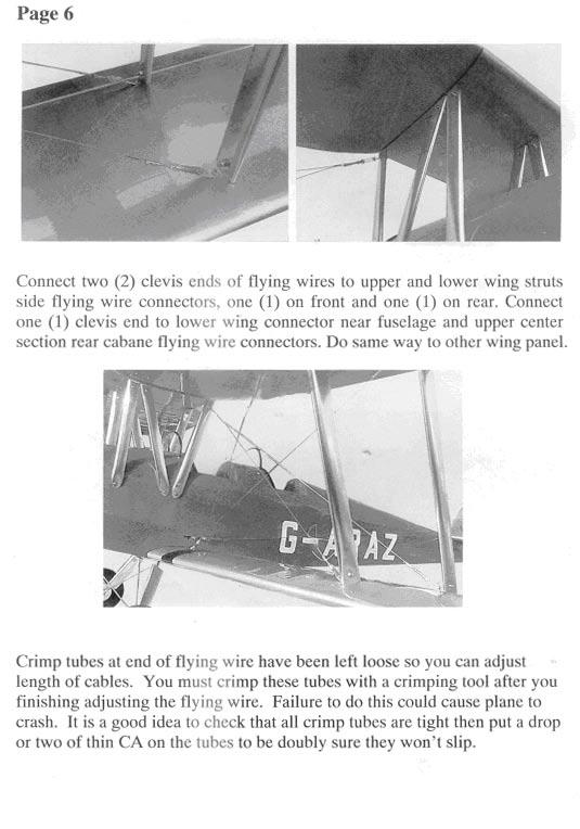
12 Fig.(11) Mounting the upper wing onto fuselage 1. Upper wing cabanes (L, M, S) 2. Wing flying wires S L M 2 Fig.(12) Flying wire and rudder control pull-pull cable sub-assembly 1. Rudder pull-pull cable 2. Flying wires 3. Clives 4. Threaded connector 5. Stainless steel tube (flattened to secure the cable) 6. Nut (to secure the clives) Step 9. Installing the wing flying wire 1) Before installing the wing flying wire sub-assembly (STM-W17), let's have a close look at the parts of the wire sub-assembly and the parts of elevator pull-pull control cable (STM-C05). The wire sub-assembly is made up of 4 parts, i.e. the clives, the threaded connector, the clamp and the cable as shown in Fig.(12). 2) As you can see, there are aluminium angle attachment (STM-W12) and flying wire connect- tor (STM- W16) already fixed on the upper and lower wing panels. Connect the clives end of the wire to the connector At all the points as shown in Fig.(13). 3) Make adjustment to get the appropriate tension of the wire such that the wing panels will not twist and the wing incidence will not be changed.
Check the tension in the wing flying wires and the pull-pull control wires. 3)Check everything which should be securely fixed.. 4)Check the C.G. point, which is to be balanced at about 6 to 6.")
13 Fig.(13) Installation of the wing flying wires 1. Wing cabanes 2. Flying wires 3. Wing struts S L Final Check before flying 1)Check the alignment and symmetry of the Kit after final assembly. 2)Check the tension in the wing flying wires and the pull-pull control wires. 3)Check everything which should be securely fixed.. 4)Check the C.G. point, which is to be balanced at about 6 to 6.5 inches (155 to165 m.m.) behind the L.E. measured at the root chord of upper wing center section. 5)Make sure that the servos operate properly and the control surfaces move in the correct direction. The travel of each control surface depends upon your own need and flight level. We recommend the following movement for your reference: Elevator 1-1/4" (32 m.m.) Rudder: 1-1/2 (38 m.m.) Ailerons: 1/2" (13 m.m.) 6)Radio and engine check as follows: * Collapse the antenna. * Before switch on your transmitter, make sure that the throttle stick is at its lowest position. * Turn on the transmitter first, and then the receiver. * Move the controls to be sure that they are all functioning correctly. * Walk away from your model for at least 100 feet (30 meters) and check all the movements. When doing this, give slow steady signals and have an assistant watch for elevator, rudder, or Aileron control flutter. Do not give fast left/right/left/right signals. * Definitely carry out the same control check with the engine running at idle as well as flat out. This safety check may show up a faulty receiver, servo or wiring/switch problems which only occur with vibration. * Don't forget to extend the antenna of your transmitter to its full length before you start flying.
14 Flying The Super Tiger Moth Using an O.S. FS-70 4-stroke engine with a 13 x 6 propeller, the Super Tiger Moth was flied perfectly for the first time, by Mr. Tony Farnan, the President of Model Engines, at the Australia's largest giant plane Fly-In during September This event was bigger than the Australia Nationals and fliers came from all over Australia. Looking at the model on the ground, these experts could not believe that the Super Tiger Moth be an ARF. Though being particular about every detail, they were satisfied with this scale model for its realistic appearance, good quality and high performance. You can also choose a 4-sroke.91 or 2-stroke.81 engine. The important thing regardless of what engine is used is to make sure that the model balances about one third back from the leading edge of the top wing. Don't hesitate to add a little weight in the nose area if necessary. It is much better to have a plane with so much wing area slightly nose heavy. The Super Tiger Moth not only looks very realistic in he air but also handles perfectly. The only adjustment is to feed in a little down trim, which perhaps would not be necessary if mounted with a lager capacity engine, such as the O.S. FS-71 which would achieve a more scalistic performance. You can fly the plane around the field most of the time half power. It's better to test fly your Super Tiger Moth on a fine day with moderate or little wind thoigh it can handle reasonably strong winds. Nevertheless, with its light weight and large wing area, naturally prefers calm conditions. On take-off, the throttle should be advanced gradually just like a full size Tiger Moth. You may need a little right rudder on the initial take-off roll. The tail will lift fairly quickly and only a little back stick is needed to allow the plane to climb out. Aerobatics, such as loops and rolls, are easy with the Super Tiger Moth once it has been trimmed out for straight and level flight. To do loops, merely face the model directly into the wind at a reasonable height. After a gentle dive apply a medium "up" elevator, taking it half off at the top of the loop and applying it again as the plane dives on the final part of the maneuvre. Rolls are commenced again by flying directly into the wind and then applying right or left aileron control. It is important, when the model is half way through its roll and on its back inverted, to give medium "down" elevator to keep the aircraft level. Similarly you can roll the plane upside down and fly inverted provided you apply the required amount of "down" elevator. Directional control whether flying upright or inverted is easy with the use of aileron movement. Spinning is easy with the Super Tiger Moth. Gradually pull throttle stick and elevator stick to stall your plane, and apply rudder to make it enter spinning. To recover from a spin requires the use of rudder against the spin, prior to or simultaneously with the elevator. In this way the model will be pitched into a even steeper attitude but will emerge in a steep dive and pick up speed rapidly. Thus, a normal dive recovery can be carried out. It is important that if spinning is to be done deliberately, it should be at good hight. Landings can be performed as wheel-less or as three-pointers if you allow for a real slow touchdown speed and keep your model straight and level. In one word, the Super Tiger Moth is designed to fly like a trainer for the beginners as well as a pattern model for the experienced pilots. Good luck and happy flying!!

15

16

17

18

19

20

21
22
Instruction Manual BULLDOG. Wingspan : 1410 mm (55.5in) : 1450 mm (57.1in) : 4900gr gr. Weight. : 6-9 Channel/ 7 servo high torque, 1standard
 : 1450 mm (57.1in) : 4900gr gr. Weight. : 6-9 Channel/ 7 servo high torque, 1standard") Wingspan : 1410 mm (55.5in) Length Weight Radio Engine : 1450 mm (57.1in) : 4900gr - 5600gr : 6-9 Channel/ 7 servo high torque, 1standard : 1.20/ 2 stroke 1.80/ 4 stroke KIT CONTENTS: We have organized
Wingspan : 1410 mm (55.5in) Length Weight Radio Engine : 1450 mm (57.1in) : 4900gr - 5600gr : 6-9 Channel/ 7 servo high torque, 1standard : 1.20/ 2 stroke 1.80/ 4 stroke KIT CONTENTS: We have organized
RADIO CONTROL MODEL ASSEMBLY INSTRUCTIONS. Wasp
 RADIO CONTROL MODEL ASSEMBLY INSTRUCTIONS Wasp TRAINER Almost ready-to-fly Wingspan 1520mm Fuselage length 1105mm Engine: 40-46 2T / 52-60 4T Electric Motor: 600-700W Radio: 5 channel / 4-5 servo RC Functions:
96in Super Decathlon ARF
 96in Super Decathlon ARF Instruction Manual Specifications Wingspan: 96in (2438mm) Length: 63.5 in (1614mm) Weight: Approx. 13lbs (6.5kg) 1 Dear Customer, Congratulations on your purchase of Super Decathlon
STICK F Class 60 Class INSTRUCTION MANUAL. Or Electric equivalent. (2T engine) (4T engine) Radio control model SPECIFICATIONS
 (4T engine) Radio control model SPECIFICATIONS") Radio control model 45 Class 60 Class (2T engine) (4T engine) Or Electric equivalent INSTRUCTION MANUAL STICK F - 1500 SPECIFICATIONS Wingspan 60 in. Length 38.5 in. Electric Motor 650 Watt Glow Engine.45
Radio control model 45 Class 60 Class (2T engine) (4T engine) Or Electric equivalent INSTRUCTION MANUAL STICK F - 1500 SPECIFICATIONS Wingspan 60 in. Length 38.5 in. Electric Motor 650 Watt Glow Engine.45
SK-50 ARF ASSEMBLY MANUAL
 SK-50 ARF ASSEMBLY MANUAL Kangke Industrial USA, Inc. 65 East Jefryn Blvd. Deer Park NY 11729 http://www.kangkeusa.com E-mail: info@kangkeusa.com Tel: 1-877-203-2377 Fax: 1-631-274-3296 Congratulations!
F3D-30 ARF ASSEMBLY MANUAL
 F3D-30 ARF ASSEMBLY MANUAL This Manuel is the sole property of Kangke Industrial USA, Inc. Reproducing any part without the consent of Kangke Industrial USA, Inc. is a lawful violation. Kangke Industrial
Radio control model INSTRUCTION MANUAL PYLON RACING. Wingspan: 1148mm (45.2 ) Radio : 4 channels Engine : two-stroke
 Radio : 4 channels Engine : two-stroke") VQA038 VQA039 Radio control model INSTRUCTION MANUAL MAGIC PYLON RACING Wingspan: 1148mm (45.2 ) Radio : 4 channels Engine :.25 -.32 two-stroke WARNING! This radio control model is not a toy. If modified
VQA038 VQA039 Radio control model INSTRUCTION MANUAL MAGIC PYLON RACING Wingspan: 1148mm (45.2 ) Radio : 4 channels Engine :.25 -.32 two-stroke WARNING! This radio control model is not a toy. If modified
SIZE.120 OR 30CC SCALE 1:5 ARF
 PC21 PILATUS MK2 SIZE.120 OR 30CC SCALE 1:5 ARF SPECIFICATION - Wingspan: 1772mm (69.72in) - Length: 2019mm (79.5 in) - Flying weight: 6.4-7.2 kg - Wing area: 57.6 dm2 - Wing loading: 113g/dm2 - Wing type:
MARACANA ASSEMBLY INSTRUCTION .40 ARF LOW WING TRAINER RADIO CONTROL MODEL. Every body can fly
 RADIO CONTROL MODEL ASSEMBLY INSTRUCTION MARACANA.40 ARF LOW WING TRAINER Every body can fly VQA085 EP GP You can use both Gas or Electric power Wingspan: 59in.(1520mm) Fuselage length: 48in.(1220mm) Engine:
RECOMMENDED MOTOR AND BATTERY SET UP
 SPECIFICATION - Wingspan: 1404mm (55.3in) - Length: 1134mm (44. 6 in) - Flying weight: 3.2-3.4 kg - Covering type: Genuine ORACOVER - Spinner size: scale type (not included) - Radio: 4 channel minimum
FUN-50 ARF ASSEMBLY MANUAL
 FUN-50 ARF ASSEMBLY MANUAL This Manuel is the sole property of Kangke Industrial USA, Inc. Reproducing any part without the consent of Kangke Industrial USA, Inc. is a lawful violation. Kangke Industrial
Table of Contents. Tail Wheel Assembly Installation.. page 01. Stabilizer Installation.. page 02. Fin Installation.. page 03
 Table of Contents Tail Wheel Assembly Installation.. page 01 Stabilizer Installation.. page 02 Fin Installation.. page 03 Elevator and Rudder Hinge Installation.. page 04 Rudder Controls.. page 05 Elevator
Instruction Manual MUSTANG P51 - EP. Wingspan : 1377mm (54.21in) : 1180mm (46.46 in) : 2200gr gr. : AXI motor 2826 or 4120
 : 1180mm (46.46 in) : 2200gr gr. : AXI motor 2826 or 4120") Instruction Manual MUSTANG P51 - EP Wingspan : 1377mm (54.21in) g Length : 1180mm (46.46 in) Weight : 2200gr - 2600gr Engine : AXI motor 2826 or 4120 Radio : 4 channel / 4 servos standard KIT CONTENTS:
Instruction Manual MUSTANG P51 - EP Wingspan : 1377mm (54.21in) g Length : 1180mm (46.46 in) Weight : 2200gr - 2600gr Engine : AXI motor 2826 or 4120 Radio : 4 channel / 4 servos standard KIT CONTENTS:
RADIO CONTROL MODEL HURRICANE
 RADIO CONTROL MODEL VQAA040G VQAA040B HURRINE Almost ready to fly SPECIFITIONS Wingspan...63 in. / 161cm Length...50 in. / 129cm Engine...50~60 2T / 70~90 4T Or Electric equivalent. RC Functions: Motor
1660mm (65.4 in) 1200mm (47.2 in) 2700gr gr 6 channel - 7 servo standard 46/ 2 stroke or 52/ 4 stroke
 1200mm (47.2 in) 2700gr gr 6 channel - 7 servo standard 46/ 2 stroke or 52/ 4 stroke") Instruction Manual CESSNA-46 1660mm (65.4 in) 1200mm (47.2 in) 2700gr - 3000gr 6 channel - 7 servo standard 46/ 2 stroke or 52/ 4 stroke KIT CONTENTS: We have organized the parts as they come out of the
Instruction Manual CESSNA-46 1660mm (65.4 in) 1200mm (47.2 in) 2700gr - 3000gr 6 channel - 7 servo standard 46/ 2 stroke or 52/ 4 stroke KIT CONTENTS: We have organized the parts as they come out of the
PITTS 12 R/C SPORT-SCALE AIRCRAFT ASSEMBLY AND INSTRUCTION MANUAL. Copyright Century UK Limited 2012
 PITTS 12 R/C SPORT-SCALE AIRCRAFT ASSEMBLY AND INSTRUCTION MANUAL 1 Warning: This radio controlled model is not a toy. It requires skill to fly and is not recommended for use by beginners. It should not
RECOMMENDED MOTOR AND BATTERY SET UP
 SPECIFICATION - Wingspan: 2190mm (86.2 in) - Length: 1907mm (75 in) - Flying weight: 9000-12000 gr - Wing area: 92 dm2 - Wing loading: 98g/dm2 - Wing type: Naca airfoils - Retract gear type: Air-retract
51in Aerobatic Series Sukhoi SU-26M Almost-Ready-to-Fly. Instruction Manual. Specifications
 51in Aerobatic Series Sukhoi SU-26M Almost-Ready-to-Fly Instruction Manual Specifications Wingspan: 51.2 in (1300mm) Length: 51.2 in (1300mm) Wing Area: 581 sq in (37.5sq dm) Flying Weight: 3.5 lb (1600g)
Instruction Manual EXTRA 260-EP. 1075mm (42.32 in) 1000mm (39.37 in) 1100gr gr. 4 channel - 4 mini servo. Axi motor 2820
 1000mm (39.37 in) 1100gr gr. 4 channel - 4 mini servo. Axi motor 2820") 1075mm (42.32 in) 1000mm (39.37 in) 1100gr - 1400gr 4 channel - 4 mini servo Axi motor 2820 KIT CONTENTS: We have organized the parts as they come out of the box for better identification during assembly.
1075mm (42.32 in) 1000mm (39.37 in) 1100gr - 1400gr 4 channel - 4 mini servo Axi motor 2820 KIT CONTENTS: We have organized the parts as they come out of the box for better identification during assembly.
MEMO. No.4341 Specification: Wing Span: 29.1 (740mm) Length: 36.6 (930mm) 2. Warranty
 Length: 36.6 (930mm) 2. Warranty") MEMO No.4341 Specification: Wing Span: 29.1 (740mm) Length: 36.6 (930mm) 2 Wing Area: 299 sq.in. (19.29 dm ) Weight: 18.9oz. (536.5g) 2 Wing loading: 0.58 oz./sq.ft (27.8g/dm ) Motor: OBL 29/27-07A Warranty
MEMO No.4341 Specification: Wing Span: 29.1 (740mm) Length: 36.6 (930mm) 2 Wing Area: 299 sq.in. (19.29 dm ) Weight: 18.9oz. (536.5g) 2 Wing loading: 0.58 oz./sq.ft (27.8g/dm ) Motor: OBL 29/27-07A Warranty
Instruction Manual. We wish you many enjoyable flights with your plane and once again thank you for your choosing a Phoenix Model product
 Instruction Manual Wing span: 1590mm (626 in) Length: 1100mm (433 in) Weight: 1500gr - 1700gr Motor: AXI 2814/10 or Motor: 500-600 w/ gear box Radio: 4 Channel / 4 servos standar Propeller: 12 x 47 We
RECOMMENDED MOTOR AND BATTERY SET UP
 SPECIFICATION - Wingspan: 6000mm (236.2 in) - Length: 2873mm (113.1 in) - Flying weight: 14-18 kg - Wing area: 219.4 dm2 - Wing loading: 64g/dm2 - Wing type: HQ airfoils - Covering type: Genuine ORACOVER
I n s t r u c t i o n M a n u a l. Instruction Manual SPECIFICATION
 I n s t r u c t i o n M a n u a l Instruction Manual SPECIFICATION - Wingspan: 3200mm (125,9 in) - Length: 1650mm (64,9 in) - Flying weight: 3000gr 3200gr - Wing area: 64.5 dm2 - Wing loading: 46g/dm2
ASSEMBLY MANUAL. Graphics and specifications may change without notice.
 NEMESISMS: SEA 111 ASSEMBLY MANUAL Graphics and specifications may change without notice. Specifications Wing span------------------------------------- 55.9in ------------------------------- 142cm. Wing
Instruction Manual. Specification:
 Instruction Manual L O W Specification: Wingspan: 133 cm (52.3 inches) Length : 104 cm (40.9 inches) Weight : 1790gr Engine : 25-32 two stroke Radio : 4 channel - 4 servo W I N G KIT CONTENTS: We have
Instruction Manual. Wingspan : 2270mm (89.37 inches) : 1870mm (73.62 inches) : 7400gr gr. : 4 channel - 6 standard servo.
 : 1870mm (73.62 inches) : 7400gr gr. : 4 channel - 6 standard servo.") Wingspan : 2270mm (89.37 inches) g Length : 1870mm (73.62 inches) Weight : 7400gr - 7600gr Radio : 4 channel - 6 standard servo Engine : 25cc-35cc KIT CONTENTS: We have organized the parts as they come
Wingspan : 2270mm (89.37 inches) g Length : 1870mm (73.62 inches) Weight : 7400gr - 7600gr Radio : 4 channel - 6 standard servo Engine : 25cc-35cc KIT CONTENTS: We have organized the parts as they come
RECOMMENDED MOTOR AND BATTERY SET UP
 SPECIFICATION - Wingspan: 1800mm (70.8 in) - Length: 1355mm (53.3 in) - Flying weight: 4100-4300 g - Wing area: 51 dm2 - Wing loading: 80g/dm2 - Wing type: Naca airfoils - Covering type: Genuine ORACOVER
RECOMMENDED MOTOR AND BATTERY SET UP
 SPECIFICATION - Wingspan: 1410mm (55.5 in) - Length: 1278mm (50.3 in) - Flying weight: 3.2-3.4 kg - Wing area: 41.3 dm2 - Wing loading: 75g/dm2 - Wing type: Naca airfoils - Covering type: Genuine ORACOVER
Assembly and Operating Manual. SPECIFICATION Length inch (640mm) Wing Span inch (705mm) Flying Weight oz (330g)
 Wing Span inch (705mm) Flying Weight oz (330g)") Assembly and Operating Manual SPECIFICATION Length 25.19 inch (640mm) Wing Span 27.76 inch (705mm) Flying Weight 11.64 oz (330g) Dear customer, Assembly and Operating manual VIPER The Radio Control System
Assembly and Operating Manual SPECIFICATION Length 25.19 inch (640mm) Wing Span 27.76 inch (705mm) Flying Weight 11.64 oz (330g) Dear customer, Assembly and Operating manual VIPER The Radio Control System
SUPER KRAFT Rearwin Speedster Assembly Manual
 SUPER KRAFT Rearwin Speedster Assembly Manual KANGKE INDUSTRIAL USA Inc. 65 East Jefryn Blvd. Deer Park New York 11729 http://www.kangkeusa.com E-mail: info@kangkeusa.com 1-877-203-2377 Fax 1-631-274-3296
SBACH SCALE 1:4 ½ ARF
 SPECIFICATION - Wingspan: 1663mm (65.5 in) - Length: 1638mm (64.5 in) - Flying weight: 4700-5200 gr - Wing area: 56 dm2 - Wing loading: 85g/dm2 - Wing type: Naca airfoils - Covering type: Genuine ORACOVER
MEMO. Assembly Manual. No Specification: Wing Span: 29.3 (830mm) Length: 29.8 (845mm) 2. Warranty
 Length: 29.8 (845mm) 2. Warranty") MEMO Assembly Manual No. 4347 Specification: Wing Span: 29.3 (830mm) Length: 29.8 (845mm) 2 Wing Area: 322.4 sq.in. (20.8 dm ) Weight: 14oz.~15oz. (420~430g) Warranty This kit is guaranteed to be free
MEMO Assembly Manual No. 4347 Specification: Wing Span: 29.3 (830mm) Length: 29.8 (845mm) 2 Wing Area: 322.4 sq.in. (20.8 dm ) Weight: 14oz.~15oz. (420~430g) Warranty This kit is guaranteed to be free
to fly. Most hardware included and all replacement parts are available.
 Instruction Manual The Thunderbolt P47 was perhaps the greatest of world war II in terms of all round performance and capability Phoenix Model has recreated a 2C - 60 class engine (or 4c 91 class) It was
EXTRA 330LX. Specifications: Code: SEA274. Graphics and specifications may change without notice. ASSEMBLY MANUAL
 ASSEMBLY MANUAL EXTRA 330LX Code: SEA274 Graphics and specifications may change without notice. Specifications: Wingspan---------------82.0 in (208.2 cm). Wing area---------------1349.4 sq.in ( 87.1 sq.dm).
MS:159 ASSEMBLY MANUAL. Graphics and specifications may change without notice.
 ASSEMBLY MANUAL MS:159 Graphics and specifications may change without notice. Specifications: Wing span ----------------------------61.8in (157cm). Wing area -----------------1100.5sq.in (71.0sq dm). Weight
48in Sbach-342. Instruction Manual. Specifications
 48in Sbach-342 Instruction Manual Specifications Wingspan: 48in (1219mm) Length: 46in (1163mm) Wing Area: 471sq in (30.4sq dm) Flying Weight: 1.8-2.0lb (800-900g) Dear Customer, www.valuehobby.com/48in-s342-arf.html
RECOMMENDED MOTOR AND BATTERY SET UP
 SPECIFICATION - Wingspan: 2000mm (78.7in) - Length: 1544mm (60.7 in) - Flying weight: 3600-3800 gr - Wing area: 66 dm2 - Wing loading: 55g/dm2 - Wing type: Naca airfoils - Covering type: Genuine ORACOVER
Wilga 20cc. Assembly Manual
 Wilga 20cc Assembly Manual Caution! You should not regard this plane as a toy! To ensure safety, please read this instruction manual thoroughly before assembly. Building and operating a model plane requires
Aviator Pro 120 ARF. Instruction Manual. Specifications
 Aviator Pro 120 ARF Instruction Manual Specifications Wingspan: 110 in (2800 mm) Length: 74 in (1870 mm) Wing Area: 1581sq in (102 sq dm) Weight: 11.4-13.4 lbs (5190-6100 g) Dear Customer, Congratulations
Instruction Manual. Wingspan : 1400mm (55.12 in) : 1370mm (53.94 in) : 2600gr gr. : 4 channel / 5 servo. : / 2 stroke_52-71 / 4 stroke
 : 1370mm (53.94 in) : 2600gr gr. : 4 channel / 5 servo. : / 2 stroke_52-71 / 4 stroke") Instruction Manual 540 Wingspan : 1400mm (55.12 in) g Length : 1370mm (53.94 in) Weight : 2600gr - 2800gr Radio : 4 channel / 5 servo Engine : 46-52 / 2 stroke_52-71 / 4 stroke KIT CONTENTS: We have organized
Instruction Manual 540 Wingspan : 1400mm (55.12 in) g Length : 1370mm (53.94 in) Weight : 2600gr - 2800gr Radio : 4 channel / 5 servo Engine : 46-52 / 2 stroke_52-71 / 4 stroke KIT CONTENTS: We have organized
MEMO. Assembly Manual. No Specification: Wing Span: 29.3 (830mm) Length: 29.8 (845mm) 2. Warranty
 Length: 29.8 (845mm) 2. Warranty") MEMO Assembly Manual No. 4347 Specification: Wing Span: 29.3 (830mm) Length: 29.8 (845mm) 2 Wing Area: 322.4 sq.in. (20.8 dm ) Weight: 14oz.~15oz. (420~430g) Warranty This kit is guaranteed to be free
MEMO Assembly Manual No. 4347 Specification: Wing Span: 29.3 (830mm) Length: 29.8 (845mm) 2 Wing Area: 322.4 sq.in. (20.8 dm ) Weight: 14oz.~15oz. (420~430g) Warranty This kit is guaranteed to be free
Instruction Manual. Congratulations on your purchase of the Flying Legends DH 60G Gipsy Moth!
 Instruction Manual Congratulations on your purchase of the Flying Legends DH 60G Gipsy Moth! Designed by the world renowned English designer David Boddington, this superb ¼ scale replica of the famous
PilotRC Trainer USER MANUAL
 PilotRC Trainer USER MANUAL Introduction Thank you for purchasing our Trainer plane. we strive to achieve a good quality quick build ARF aircraft. It requires the least amount of assembly of any ARF kit
Please read all instructions carefully before assembly and flight!
 c c Please read all instructions carefully before assembly and flight! Thank you for purchasing the. This model is designed for the intermediate to advanced flyer. The model is receiver-ready and includes
Instruction Manual. Wingspan : 1884 mm (74.17 in) Length. Weight. Engine. : 4 channels / 5 servo standard. : 1450 mm (57.
 Length. Weight. Engine. : 4 channels / 5 servo standard. : 1450 mm (57.") Wingspan : 1884 mm (74.17 in) Length : 1450 mm (57.09 in) Weight : 4000 gr Engine : 60 two strokes Radio : 4 channels / 5 servo standard KIT CONTENTS: We have organized the parts as they come out of the
Wingspan : 1884 mm (74.17 in) Length : 1450 mm (57.09 in) Weight : 4000 gr Engine : 60 two strokes Radio : 4 channels / 5 servo standard KIT CONTENTS: We have organized the parts as they come out of the
AVIATOR 25 ARF Almost Ready-to-Fly
 AVIATOR 25 ARF Almost Ready-to-Fly Instruction Manual Specifications Wingspan: 54.3 in (1380mm) Length: 45.2 in (1150mm) Wing Area: 438 sq in (34sq dm) Flying Weight: 3.8 b (1700g) Dear Customer, Congratulations
DeHavilland DH88 Comet
 DeHavilland DH88 Comet INSTRUCTION MANUAL A semi scale ARF R/C model of the famous winner of the 1934 MacRobertson, England to Australia Air Race. Technical Specification Wingspan: 88 inches (2235 mm)
ASSEMBLY MANUAL. Kit features. MS:110
 MS:110 ASSEMBLY MANUAL Graphics and specifications may change without notice. Specifications: Wing span-------------------------------------------------- 62.9 in---------------------------------------
MS:176 ASSEMBLY MANUAL. Graphics and specifications may change without notice.
 ASSEMBLY MANUAL MS:176 Graphics and specifications may change without notice. Specifications: Wing span ------------------------------98.4in (250cm). Wing area ----------------1576.4sq.in (101.7sq dm).
: 6 channel - 9 servo
 g Wingspan : 2005mm (78.94 inches) Length : 1640mm (64.57 inches) Weight : 6400g - 6600g Engine : 25cc - 35cc Radio : 6 channel - 9 servo KIT CONTENTS: We have organized the parts as they come out of
CAP 232 ASSEMBLY MANUAL
 CAP 232 MS: ASSEMBLY MANUAL SEA 91 Graphics and specfications may change without notice. Specifications Wingspan------------------------------------ 65 in --------------------------------- 165cm. Wing
Instruction Manual. Wingspan : 1694mm (66.69 in) : 1470mm (57.87 in) : 3200gr gr. : 61 two stroke/ 71 four stroke. : 6 channel / 7 servo
 : 1470mm (57.87 in) : 3200gr gr. : 61 two stroke/ 71 four stroke. : 6 channel / 7 servo") Wingspan : 1694mm (66.69 in) g Length : 1470mm (57.87 in) Weight : 3200gr - 3800gr Engine : 61 two stroke/ 71 four stroke Radio : 6 channel / 7 servo KIT CONTENTS: We have organized the parts as they
Wingspan : 1694mm (66.69 in) g Length : 1470mm (57.87 in) Weight : 3200gr - 3800gr Engine : 61 two stroke/ 71 four stroke Radio : 6 channel / 7 servo KIT CONTENTS: We have organized the parts as they
Pitts Challenger m (100cc) MANUAL
 MANUAL") Pitts Challenger 87 2.20m (100cc) MANUAL 1- Introduction: WELCOME TO THE PILOT-RC TEAM! Thank you for choosing a Pilot-Rc plane as your next model. We hope that you enjoy many successful and exhilarating
Pitts Challenger 87 2.20m (100cc) MANUAL 1- Introduction: WELCOME TO THE PILOT-RC TEAM! Thank you for choosing a Pilot-Rc plane as your next model. We hope that you enjoy many successful and exhilarating
(Glider) ASSEMBLY MANUAL
 ASSEMBLY MANUAL") (Glider) MS:132 ASSEMBLY MANUAL Graphics and specifications may change without notice. Specifications: Wing span ------------------------------118.1in (300cm). Wing area ---------------------902.1sq.in
(Glider) MS:132 ASSEMBLY MANUAL Graphics and specifications may change without notice. Specifications: Wing span ------------------------------118.1in (300cm). Wing area ---------------------902.1sq.in
YAK54 MK2. GP/EP size.120/20cc SCALE 1:4 ¾ ARF. Instruction Manual. version. version
 Instruction Manual GP EP version version GP/EP size.10/0cc SCALE 1:4 ¾ ARF SPECIFICATION - Wingspan: 168 (66.3 in) - Length: 1605mm (63.1 in) - Flying weight: 4700-500 gr - Wing area: 54.7 dm - Wing loading:
H-King R/C scale model series. instruction manual
 H-King R/C scale model series instruction manual 1. Please read this manual carefully and follow the instructions of the manual before you use this products. SAFETY INSTRUCTIONS 2. Our airplane is not
: 7 channel - 9 servo, Hi-Torque ( Minimum 6 kg ).
.") g Wingspan : 1820mm (71.65 inches) Length : 1625mm (63.98 inches) Weight : 6900gr Engine : 25cc - 35cc Radio : 7 channel - 9 servo, Hi-Torque ( Minimum 6 kg ). KIT CONTENTS: We have organized the parts
g Wingspan : 1820mm (71.65 inches) Length : 1625mm (63.98 inches) Weight : 6900gr Engine : 25cc - 35cc Radio : 7 channel - 9 servo, Hi-Torque ( Minimum 6 kg ). KIT CONTENTS: We have organized the parts
LANIER R/C S PREDATOR II ARF
 LANIER R/C S PREDATOR II ARF WARNING! THIS IS NOT A TOY! THIS IS NOT A BEGINNERS AIRPLANE This R/C kit and the model you will build from it is not a toy! It is capable of serious bodily harm and property
Climber is 776B101101
 is Climber 776B101101 Introduction Product Introduction NE R/C 776B is a good-sized glider designed by Nine Eagles Company latest, whose wing span is up to 2008mm. You only need to assemble the aerofoil
CAUTION : this plane is not a toy and should be kept away children under 16 years of age! Before use, please carefully read this manual.
 Wing Span:74in/1880mm; Flying Weight:7700-7900g; Wing Area:112sq.dm; Radio:8channels 9-10servos; Length:72in/1829mm; Engine:50CC GAS; CAUTION : this plane is not a toy and should be kept away children
Assembly and Operating Manual HR-100. Specification: *Length: 41-7/10"(1060 mm) *Wing span: 49-1/5"(1250 mm) *Flying weight: 45.
 *Wing span: 49-1/5(1250 mm) *Flying weight: 45.") Assembly and Operating Manual HR-100 Specification: *Length: 41-7/10"(1060 mm) *Wing span: 49-1/5"(1250 mm) *Flying weight: 45.9 oz (1300g) Dear customer, Congratulations on your choice of a factory-assembled
Assembly and Operating Manual HR-100 Specification: *Length: 41-7/10"(1060 mm) *Wing span: 49-1/5"(1250 mm) *Flying weight: 45.9 oz (1300g) Dear customer, Congratulations on your choice of a factory-assembled
Lanier R/C F-4 Phantom
 Lanier R/C.40-.46 F-4 Phantom Almost Ready to Fly WARNING! THIS IS NOT A TOY! THIS IS NOT A BEGINNERS AIRPLANE This R/C kit and the model you will build from it is not a toy! It is capable of serious bodily
ALMOST READY TO FLY. Wing Span in cm. 2
 ASSEMBLY MANUAL ALMOST READY TO FLY MS:X9 Specifications Wing Span --------------------------61.4 in ---------------------------156cm. 2 Wing Area --------------------------606.1 sq.in ------------------
Assembly Manual For. Wingspan: 88 in Wing area: sp in Length: 78.8 in Engine: 50CC.
 Assembly Manual For Wingspan: 88 in Wing area: 1479.8 sp in Length: 78.8 in Engine: 50CC www.pilot-rc.com INTRODUCTION Thank you for purchasing our new 50 cc model. We strive to bring you the most complete
64MM F-16 Fighting Falcon V2
 64MM F-16 Fighting Falcon V2 SIMPLE Simple assembly RIGID STRONG DURABLE EPO STABLE SMOOTH FLYING PERFORMANCE FMSMODEL.COM Table of Contents Introductions 3 Contents of Kit 4 Assemble the plane 5 Battery
1 All our plane have the matching carbon fiber servo arms, carbon fiber main and tail landing gear, carbon fiber spinner and wood propeller available.
 Our airplane model: 1 All our plane have the matching carbon fiber servo arms, carbon fiber main and tail landing gear, carbon fiber spinner and wood propeller available. 2 Pre-glued cowling ring with
ASSEMBLY MANUAL. Kit features. MS:76
 ASSEMBLY MANUAL MS:76 Graphics and specfications may change without notice. Specifications: Wingspan---------------------------------------------------- 82.8 in------------------------------------- 210.3cm.
HERO 3D SCALE 1:6 ARF
 Instruction Manual SPECIFICATION - Wingspan: 1500mm(59 in) - Length: 1410mm (55.5 in) - Flying weight: 2100-2300 gr - Wing area: 58 dm2 - Wing loading: 39g/dm2 - Covering type: Genuine ORACOVER - Gear
RECOMMENDED MOTOR AND BATTERY SET UP
 SPECIFICATION - Wingspan: 1669mm (65.7in) - Length: 1229mm (48.43 in) - Flying weight: 3300-3400 gr - Wing area: 44.2 dm2 - Wing loading: 67g/dm2 - Wing type: Naca airfoils - Covering type: Genuine ORACOVER
LANIER R/C S WARNING! THIS IS NOT A TOY! THIS IS NOT A BEGINNERS AIRPLANE
 LANIER R/C S PREDATOR 500 ARF WARNING! THIS IS NOT A TOY! THIS IS NOT A BEGINNERS AIRPLANE This R/C kit and the model you will build from it is not a toy! It is capable of serious bodily harm and property
PIPER J - 3 CUB 26s cu. in. displacement 2-stroke 0.30 cu. in. displacement 4-stroke. Specifications
 ALMOST-READY-TO-FLY INSTRUCTION MANUAL PIPER J - 3 CUB 6s 0.5-0.3 cu. in. displacement -stroke 0.30 cu. in. displacement -stroke Require s : - channel radio w/ standard servos Wing Span Wing Area Flying
Instruction Manual. Wingspan : 1400 mm (55.12 inch) : 1480 mm (58.27 inch) : 5500gr gr. : 6-9 channel/ 8 servo high torque,1 standard
 : 1480 mm (58.27 inch) : 5500gr gr. : 6-9 channel/ 8 servo high torque,1 standard") Wingspan : 1400 mm (55.12 inch) g Length : 1480 mm (58.27 inch) Weight : 5500gr - 6000gr Radio : 6-9 channel/ 8 servo high torque,1 standard Engine : GT 22 OS KIT CONTENTS: We have organized the parts
Wingspan : 1400 mm (55.12 inch) g Length : 1480 mm (58.27 inch) Weight : 5500gr - 6000gr Radio : 6-9 channel/ 8 servo high torque,1 standard Engine : GT 22 OS KIT CONTENTS: We have organized the parts
MS:183 ASSEMBLY MANUAL. Graphics and specifications may change without notice.
 MS:183 ASSEMBLY MANUAL Graphics and specifications may change without notice. Specifications: Wing span ------------------------------79.9in (203cm). Wing area -----------------1165.6sq.in (75.2sq dm).
Assembly and Operating Manual. 3D cap-232. Specification: *Length: 25-9/10"(655mm) *Wing Span: 29-3/5"(750mm) *Flying Weight: 15-9/10 oz (450g)
 *Wing Span: 29-3/5(750mm) *Flying Weight: 15-9/10 oz (450g)") Assembly and Operating Manual 3D cap-232 Specification: *Length: 25-9/10"(655mm) *Wing Span: 29-3/5"(750mm) *Flying Weight: 15-9/10 oz (450g) Dear customer, Congratulations on your choice of a factory-assembled
Assembly and Operating Manual 3D cap-232 Specification: *Length: 25-9/10"(655mm) *Wing Span: 29-3/5"(750mm) *Flying Weight: 15-9/10 oz (450g) Dear customer, Congratulations on your choice of a factory-assembled
Neptune Seaplane25 ARF. Instruction Manual. Specifications
 Neptune Seaplane25 ARF Instruction Manual Specifications Wingspan: 1270mm (50in) Length: 1155mm (45.5in) Wing Area: 34.8 sq dm (539.4 sq in) Weight: 1950g (4.30lbs) Product Highlights Removable hatch on
MS:158 ASSEMBLY MANUAL. Graphics and specifications may change without notice.
 MS:158 ASSEMBLY MANUAL Graphics and specifications may change without notice. Specifications: Wing span ------------------------------70.9in (180cm). Wing area -----------------644.8sq.in (41.6sq dm).
PilotRC EDGE USER MANUAL. WINGSPAN:1710mm LENGTH:1554mm
 PilotRC EDGE540 67 USER MANUAL WINGSPAN:1710mm LENGTH:1554mm Introduction Thank you for purchasing our Edge 540 plane. we strive to achieve a good quality quick build ARF aircraft. It requires the least
ASSEMBLY MANUAL. Kit features. MS:88
 MS:88 ASSEMBLY MANUAL Graphics and specfications may change without notice. Specifications: Wingspan-------------------------------------------------- 70.9 in--------------------------------------- 180cm.
INSTRUCTION MANUAL BOOK
 INSTRUCTION MANUAL BOOK ITEM CODE BH57. SPECIFICATION Wingspan: 1,470 mm. 57.87 in. Length : 1,180 mm. 46.46 in. Weight : 2.7 Kg. 5.94 Lbs. Engine : 46 cu.in 2 stroke. 52 cu.in 4 stroke. Radio : 4 channels.
40 EP Gee Bee Y Scale ARF V2 Instruction Manual Specs:
 40 EP Gee Bee Y Scale ARF V2 Instruction Manual Specs: Wing Span: 40" Overall length: 30" Wing area: 306 sq. in Ready to fly weight: 28~32 oz Motor/Engine: Electric: Uranus-28309 brushless outrunner motor,
RECOMMENDED MOTOR AND BATTERY SET UP
 SPECIFICATION - Wingspan: 2567mm (101in) - Length: 2190mm (86.2 in) - Flying weight: 11-13 kg - Wing area: 101 dm2 - Wing loading: 99g/dm2 - Wing type: Naca airfoils - Covering type: Genuine ORACOVER -
I/C FLIGHT GUIDELINES
 SPECIFICATION - Wingspan: 3500mm (137.8 in) - Length: 1650mm (64.96 in) - Flying weight: 3700-4000 gr - Wing area: 75 dm2 - Wing loading: 49g/dm2 - Wing type: HQ profile - Covering type: Genuine ORACOVER
8mm EPP Acrocub. Instruction Manual. Specifications
 8mm EPP Acrocub Instruction Manual Specifications Wingspan: 34.6 in (880mm) Length: 31.5 in (800mm) Wing Area: 213.9 sq in (13.8sq dm) Flying Weight: Approx. 9oz (270g) Dear Customer, www.valuehobby.com/8mm-epp-acrocub.html
Instruction Manual. Wingspan : 1670mm. : 3400gr gr. : 61/75 two stroke. : 5 servo + 1 servo retract / 6 channel
 Wingspan : 1670mm g Length Weight Engine Radio : 1350mm : 3400gr - 4000gr : 61/75 two stroke : 5 servo + 1 servo retract / 6 channel KIT CONTENTS: We have organized the parts as they come out of the box
P-47D THUNDERBOLT cu. in. displacement 4-stroke. Requires: 6-channel radio w/ 7 standard servos and 2 low profile retract servos.
 INSTRUCTION MANUAL P-7D THUNDERBOLT 1.20 cu. in. displacement -stroke Requires: 6-channel radio w/ 7 standard servos and 2 low profile retract servos Specifications Wing Span Wing Area Flying Weight Fuselage
ASSEMBLY MANUAL. Specifications
 Kit features. Ready-made minimal assembly & finishing required. Ready-covered covering. Photo-illustrated step-by-step Assembly Manual. ASSEMBLY MANUAL Specifications Wingspan--------------------------------
ASSEMBLY MANUAL. Graphics a nd s pecifications m ay c hange w ithout n otice.
 MS: 86 ASSEMBLY MANUAL Graphics a nd s pecifications m ay c hange w ithout n otice. Specifications Wing span-------------------------------------- 70.9 in------------------------------ 180cm. Wing area--------------------------------------
YAK 54 Aerobatic Model Aircraft Assembly and Instruction Manual
 YAK 54 Aerobatic Model Aircraft Assembly and Instruction Manual Warning: This radio controlled model is not a toy. It requires skill to fly and is not recommended for the novice pilot. It should not be
Instruction Manual book
 Instruction Manual book SPECIFICATION Wingspan : 1,800mm. 70.87 in. Length : 1,350 mm. 53.15in. Weight : 3.6kg. 7.92lbs. Parts Listing required (not included). Glow Engine : 55-61 2 stroke. 91 4 stroke.
HIGH WING MK2 GP/EP ARF SCALE
 SONIC HIGH WING MK2 GP/EP.25-.32 ARF SCALE 1:10 SPECIFICATION - Wingspan: 1340mm (52.7in) - Length: 1040mm (40.9 in) - Flying weight: 1800-2000 gr - Wing area: 27 dm2 - Wing loading: 79g/dm2 - Wing type:
ARF TRAINER KIT ASSEMBLY MANUAL BOOMERANG EP. ALMOST READY TO FLY
 WWW.SEAGULLMODELS.COM ASSEMBLY MANUAL BOOMERANG EP ARF TRAINER KIT Graphics and specifications may change without notice. MS: 211 ALMOST READY TO FLY Specifications: Wingspan---------------56.0 in (142.2
RECOMMENDED MOTOR AND BATTERY SET UP
 Instruction Manual SPECIFICATION - Wingspan: 1418mm (55.8 in) - Length: 1314mm (51.7 in) - Flying weight: 2700-3200 gr - Wing area: 36.8 dm2 - Wing loading: 76g/dm2 - Wing type: Naca airfoils - Covering
Instruction Manual book
 book SPECIFICATION Wingspan : 1,450 mm 57.09 in. Length : 1,200mm 47.24in. Weight : 3.1 kg 6.82 Lbs. Radio : 05 channels. Servo : 07 servos. Engine : 61-75 2 stroke. 91 4 stroke. Made in Vietnam. This
SU-31 PROFILE ELECTRIC ARF ASSEMBLY MANUAL
 SU-31 PROFILE ELECTRIC ARF ASSEMBLY MANUAL 1 TABLE OF CONTENTS Page Aeroworks Contact Information... 3 Introduction.. 4 Kit Contents... 5 Items needed to complete 6 Wing Assembly. 7 Stab Assembly. 10 Flight
Specifications. Kit features.
 A S S E M B L Y M A N U A L MS:58 Graphics and Specfications may change without notice. Specifications Wingspan---------------------------------------- 70.9 in---------------------------- 182cm. Wing area----------------------------------------
Ultimate EP. Before commencing assembly, please read these instructions thoroughly. I NSTRUCTI ON M ANUAL. Warning! This model is not a toy.
 I NSTRUCTI ON M ANUAL Before commencing assembly, please read these instructions thoroughly. Ultimate EP (GM05) Specifications Wing Span: 3.5 in / 85 mm Wing Area: 357 sq in / 3 sq dm Flying Weight: 4
ASSEMBLY MANUAL. Specifications
 ASSEMBLY MANUAL MS: SEA 82 Graphics and specfications may change without notice. Specifications Wingspan-------------------------------------- 70.9 in------------------------------ 180cm. Wing area-------------------------------------
Please read all instructions carefully before assembly and flight!
 Please read all instructions carefully before assembly and flight! Thank you for purchasing the Mig-15. This model is designed for the intermediate to advanced flyer. The model is receiver ready and includes
Instruction Manual book
 Instruction Manual book ITEM CODE:BH118. SPECIFICATION Wingspan : 1,050 mm 41.34 inches. Length : 950mm 37.4 inches. Weight : 1 kg 2.2 lbs. Radio : 04 channels. Servo : 4 mini servos. Motor : KMS 2814/05
PIPER J - 3 CUB 48S cu. in. displacement 2-stroke cu. in. displacement 4-stroke. Specifications
 ALMOST-READY-TO-FLY INSTRUCTION MANUAL PIPER J - 3 CUB 8S 0.0-0.6 cu. in. displacement -stroke 0.5-0.56 cu. in. displacement -stroke Require s : - channel radio w/ 5 standard servos Specifications Wing