Design and Optimization of an FSAE Frame, Suspension, and Business Portfolio
|
|
|
- Moses Laurence Bell
- 6 years ago
- Views:
Transcription
1 Design and Optimization of an FSAE Frame, Suspension, and Business Portfolio Submitted to the faculty of Worcester Polytechnic Institute In partial fulfillment of the requirements for this Major Qualifying Project By: Constantine Scaperdas, ME Jonathan Ross, ME Christian Strobel, ME David Powers, MGE Date: 4/27/17 Approved by: Professor David C. Planchard, ME Advisor Professor John C. Hall, ME Co Advisor Professor Kevin M. Sweeny, Business Co Advisor
2 Abstract The purpose of this MQP was to design and manufacture a new frame and suspension for use in the 2018 FSAE competition. Through analysis of the car entered in the 2016 competition, research, feedback from the previous designers, and critiques from the competition judges, optimized designs were developed. Improvements were made to the weight, ergonomics, impact strength, and reliability. Components were designed to incorporate the engine and other components from the previous car. Through the use of FEA the frame and suspension were tested to ensure the performance and safety of the final designs. The car's design also took into account the 2018 FSAE rules to ensure the car would be able to enter the competition easily and satisfy the judges requirements. Additionally changes were made to ensure an improved placement in the 2018 FSAE competition. Outlines for the business components of the competition were created including a cost report outline, business presentation outline, and standardized process for recording expenses. Page 2 of 95
3 Acknowledgements We would like to thank David Planchard, John Hall, Kevin Sweeny, Zachary Sears, Adrian Pickering, Steven Murphy, V3 Cartesian tubing, Barbra Furhman and WPI SAE for all their help during our project. You all were critical in making this project possible. Page 3 of 95
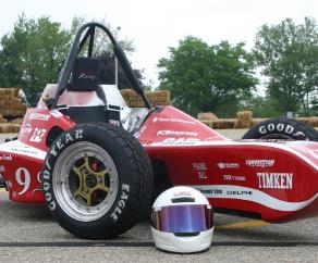
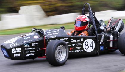
4 Executive Summary The Formula SAE competition is organized by the Society of Automotive engineers, and was developed to allow college students to design, manufacture, and drive a formula style racecar. The cars are meant to be build and marketed as weekend racers for non-professional drivers. The teams compete against one another is a series of events testing different components of the car to decide who has the best overall design. The 2016 competition was WPI s best ever placement in the FSAE competition. Due to the strong results, instead of redesigning the entire car the WPI FSAE team will be using the 2016 car as a basis and making improvements to the designs of several subsystems. This represents the first year in a two-year build process. The 2017 project will the focus on making tune-ups and getting the car running for the 2018 FSAE Michigan competition. The purpose of this MQP was to design and manufacture a new frame and suspension for use in the 2018 FSAE competition. Through analysis of the car entered in the 2016 competition, research, feedback from the previous designers, and critiques from the competition judges, optimized designs were developed. The frame used in the 2016 competition was designed to be as strong as possible and accommodate any driver. These specifications though made the frame heavy and bulky. Our goals were to lighten the frame and improve the ergonomics. These improvements were made as a weight decrease improves the mechanical performance of the car. While the ergonomics make the car easier to drive. We believe both of these will improve our placement in the 2018 FSAE competition. The in order to achieve the weight decrease several changes were made to the overall frame. The tubes on the old frame were made at a high outer diameter to increase strength so using the FSAE minimum requirements for tubing we decreased the diameter to tubes to the minimum to decrease weight. Additionally, the front section of the car was made smaller, this cut weight and allowed us to make the car more compact. To prove that the new frame was comparable in strength to the previous iteration analysis was required. Finite element analysis (FEA) through Solidworks software was performed to determine the strength of our frame. Tests were performed simulation front impacts, side impacts, and the car rolling over. The same testes were also performed on the previous frame in order to equate the two. Through the tests we found that our frame passed the FSAE requirements and was comparable in not stronger that the previous frame. The major issue with the frame ergonomics was that the front of the car was difficult to see over due to a large front roll hoop. This worked well with the weight decrease as shirking the front roll hoop achieved both goals. Additionally, the size of the front bulkhead was rotated this allows for an overall slimmer can and create a sleeker profile. Page 4 of 95
5 The suspension of the car from 2016 also had several issues that needed to be addressed. The bearings in the suspension had issues with binding where the suspension would not return to its rest state. Additionally, the geometry and the strut assemblies needed to be altered to fit the updated frame. New frame tabs were designed and manufactured to connect the suspension members to the frame with spherical joints to eliminate binding. The springs and shocks were relocated to remain in plane with the suspension to eliminate side loading and bearing wear. Finally, the thickness and diameter of the suspension arms was reduced to save weight. Finite element analysis has determined the thinner arms maintain strength. In addition to the physical car, there were managerial flaws within the team. The team was made up of entirely engineers with no students to develop the management, marketing, and financial side of the competition. The lack of business minded team members caused the team to not achieve the most points possible while the team was at competition. The team lack of effort into create the proper business materials for the competition caused the teams rank to decrease. With proper attention being pushed to the three major business sections of the competition, there was a guarantee of an increase in points as well as a better understanding of what the project is ultimately trying to accomplish. The goals of the business team were to develop a set of outlines that could be passed down from year to year. These outlines are set to help future business or even ME team members create the documentation needed to understand, create, and submit each of the two major aspects of the project. The Business Logic Case was the first document that the team should create. In years past someone on the team who was just aiming to get it completed threw it together. The goal of this document is to teach participants about the factors that need to be considered when a company embarks on development of a new product. These include: cost; identification of market and likely sales volume; profitability; the key features applicable to the selected vehicle concept and target market size. The second part is the cost analysis. The cost analysis should be submitted prior to the competition before the specified due date. As well as submitting online, the report should be handed in as a hard copy the day of the competition. The main point of the cost analysis is to teach the participants that cost and a budget are significant factors and must be taken into account in any engineering exercise Ensure the teams develop their cars within a reasonable budget, many teams have worked what may seem like an unlimited budget, so it is very easy to get ahead of yourself with purchasing and manufacturing part for the single car, but it is important to remember that the grand scale of the competition is to create a car that car be mass produced. Page 5 of 95
6 Page 6 of 95
7 Contents Abstract... 2 Acknowledgements... 3 Executive Summary... 4 List of Figures... 9 Background Overview of FSAE competition Events Breakdown Competition Results Project Approach Goals for MQP Full CAD Model Frame Frame Introduction Previous Year s Design Frame Redesign Improvements to Frame Design Final Frame Design FEA Simulation Results Final Frame Ergonomics Frame Manufacturing Frame Recommendations Suspension Previous Suspension Design A-Arms Steering Improvements to Suspension Design Spherical Joints Suspension Tabs Reduce Size of A-Arm Tubing Front Suspension Geometry Toe Bars Redesigned Pullrod System Page 7 of 95
8 Suspension Recommendations Overview of Business MQP and FSAE Team Connection Miscommunication Weekly Team and MQP Meetings Sponsorship Opportunities Requesting Sponsorship Database of sponsors Business Logic Case Business Logic Case Outline Business Logic Case Sample Understanding the Budget and Cost Analysis Recreating the Cost Report Moving Forward with the Cost Report and ebom Cost vs. Price Form Cost Analysis Outline Future Business Recommendations References Appendix Appendix 1: Cornell University FSAE 2016 sponsorship packet Appendix 2: Frame Comparison Analysis handout Appendix 3: Structural Equivalency Spreadsheet Highlights Appendix 4: Business Logic Case Outline Appendix 5: Business Logic Case Appendix 6: Cost Report Outline Appendix 7: Cost vs Price Form Page 8 of 95
9 List of Figures Figure 1: FSAE Scoring Figure 2: 2016 FSAE Scoring Results Figure 3: 2016 frame with added structural members highlighted Figure 4: Frame design from last year's car color coded for tube size: blue=1x0.065in, red=1x0.095in, grey=0.625x0.065in Figure 5: Redesigned Frame with wider rear and adjusted roll hoop positions Figure 6: Redesigned frame with narrowed cockpit and lowered front roll hoop Figure 7: excerpt from Formula SAE rule book detailing minimum tube sizes needed for different sections of the frame Figure 8: color coded redesigned slim frame: Red = 1x0.095in tubes, Blue = 1x0.065in tubes, green = 1x0.049in tubes Figure 9: final frame design featuring redesigned roll hoops with added supports Figure 10: Displacement chart for front impact test Figure 11: Factor of safety chart for front impact test Figure 12: displacement chart for side impact test Figure 13: factor of safety chart for side impact test Figure 14: Displacement chart for main roll hoop 2016 car Figure 15: Displacement chart for main roll hoop impact test Figure 16: Factor of safety chart for main roll hoop impact test Figure 17: Displacement chart for front roll hoop impact test Figure 18: Factor of safety chart for front roll hoop impact test Figure 19: cockpit opening template as shown in the Formula SEA rulebook Figure 20: cockpit opening template test showing minimum clearance of 4mm Figure 21: 95th percentile male driver template as depicted in the Formula SAE rule book Figure 22: excerpt from Formula SAE rulebook depicting 2 inches minimum clearance during 95th percentile driver template test Figure 23: 95th percentile driver test showing 2in helmet clearance and 7.92 inches leg clearance from impact attenuator Figure 24: Cockpit internal cross-section template as depicted in the Formula SAE rulebook Figure 25: Cockpit internal cross-section template test showing 16 mm of clearance Figure 26: Frame Figure 27: Previous suspension Figure 28: Camber gain in a double wishbone suspension Figure 29: Scrub radius explained Figure 30: Rear frame weighted design matrix Figure 31: Suspension weighted design matrix Figure 32: 2016 Single DOF suspension joint Figure 33: Cylindrical rod end with male threads Figure 34: Spherical joint assembly Figure 35: Spherical joint assembly exploded view Figure 36: Rear suspension tabs with extra toe bar tab Figure 37: Example and exploded view of redesigned tab and bracket system Figure 38: Weight analysis of suspension tabs Figure 39: Factor of Safety analysis of A-arm bracket Page 9 of 95
10 Figure 40: Force Derivations Figure 41: Deformation analysis of A-arms during cornering Figure 42: Designing the front suspension geometry Figure 43: Previous toe bar design Figure 44: Updated toe bar design with new tabs Figure 45: Previous pullrod suspension Figure 46: Updated design Figure 47: Rocker Deformation Test Figure 48: Previous Years Cost Report Figure 49: Recreated Cost Report Page 10 of 95
11 Background The project required research into how the FSAE competition functions and the best way to execute our project. FSAE provides a detailed rule booklet to follow detailing requirement to compete in the competition. Additionally the team felt it important to establish how we would execute the project and what the goals of the project were. Overview of FSAE competition Formula SAE is a competition simulating that a manufacturing company contracted our design team to develop a Formula-style racecar. The car is evaluated for its ability to be manufactured and sold as a weekend racer for non-professional autocross. Each student team designs, builds and tests a prototype based on a set of rules whose purpose is both to ensure safety and promote problem solving among the team. The vehicle is inspected with tests to ensure it complies with the competition rules; in addition, the vehicle will be judged in a number of performance tests on track. The rest of the judging is completed by experts from motorsports, automotive, aerospace and supplier industries on student design, cost and sales presentations. The events are broken up into two categories, static events and dynamic events. Events Breakdown The static event include any event where the car is not moving and includes three events a presentation marketing the car, the engineering design, and the cost analysis. The presentation is done to a panel of judges who evaluate the business case for the car and are treated as the executives of a corporation. Judges evaluate how it meets the demand of the market, the ability to generate a profit and how well it can be marketed. The design event team are able to explain the design choice they made in developing the car, allowing the teams a chance to showcase their improvements and there they invested time in the car. The cost analysis is done with a standard format to show where the costs we allotted when building the car, along with the total cost of manufacturing the car ( Formula SAE Rules). These three events are worth 325 out of the total 1000 point in the competition showing that priority is put on how the car functions. The dynamic events are broken up into acceleration, skid pad, autocross, efficiency and endurance. Before the car even enters the events it must go through an inspection to test that the car fulfills all the rules of the competition. The acceleration test sees what speed the car can reach over 75m. The skid pad event measures the car's ability to corner through a turn, by having it race through a figure eight pattern. The autocross event is done to evaluate how the car races and is a timed race on a closed course. Efficiency and endurance are done together, the car is raced to test durability, reliability, and to test efficiency the gas level in the car is measured at the end of the heat. Given Below is the point breakdown for the event in Page 11 of 95
12 Figure 1: FSAE Scoring 2016 Competition Results At Formula SAE 16 Michigan WPI can in 67 th out of a total 115 teams with a total of points out of the total 1000 figure 2. Figure 2: 2016 FSAE Scoring Results This represents the best scores and finishing position that WPI has even had and a huge improvement in score from the 223 WPI received in Although there are still areas where we can garner more points. On the Static portion of the events we had issues with the cost of our car. Due to time constraints for the team the cost portion and presentation were put together hastily before the competition. The cost our car came out to be 37,406 dollars. Way above the cost of the other cars which averages to around 16,000 dollars, placing us 109/115 teams. We additionally struggled with the business presentation. Teams will typically bring in business majors for this portion of the competition although ours was done last minute before the competition and suffered for this, the team came 94/115 on the presentation. The design team was solid, the issues here were the mainly with the toe bar and the suspension tabs. The issue with the toes bar was that it was mounted to the frame and not to the a-arms. The suspension tabs did not allow for easy motion as there was friction that stopped the wheels returning to their full unspring position. Page 12 of 95
13 For the dynamic competitions there are several areas of improvement. The team missed the acceleration competition because there were issues with the tech and the car was not approved to compete. We had a skid pad time of seconds significantly more than the for the top team causing to lose significant points. In autocross our lap times were low with the best being seconds while the best team had a time of 45 seconds. Even boosting our time to 60 seconds would have been a 15 point increase. The endurance competition is a place for major improvement as we took 1889 seconds to finish while the top came in around 1416 seconds, but the top is so much higher the point drop off is rapid, the 15th team only got 200 points, out of the total 275. Project Approach In 2016 WPI competed in the FSAE Michigan competition so this year represents the first year in the build cycle. When starting the project our team first had to take into account the build cycle the WPI SAE club desired for the new car. The consensus was that since the 2016 car was a complete redesign and got WPI its highest score ever in competition, we would stick with the two year build cycle, but not completely redesign the car. The new approach to the project is to spend the first year of the build cycle optimizing and redesigning a couple subsystems on the car. The second year would be spent tuning up the other systems in the car and preparing for competition. In accordance with the needs of the team, the systems chosen to be redesigned were the frame and suspension. Additionally the weakest part of the 2016 team in competition was its performance in the business portion of the competition. We felt this was important to develop during the first year of the build cycle as purchases for the car to compete in 2018 begin now and recording these purchases accurately are key to the team s success. Goals for MQP With the 2016 competition the team established a solid baseline for us to work off this year. Although there was substantial information missing about the previous car and its results during competition. We wanted to work through marginal improvements to boost our scores without doing a complete redesign on our 2 year build cycle. We also want to make sure that any work we do is easy to access and edit so future teams have a strong base and can begin work immediately. The focus our project was to redesign the frame, suspension and business portions of our project to improve scores. Using the comments of the club and the judges last year our goal were: a. Keep all files accessible, easy to edit, and organized b. Make Incremental changes to 2016 Car design c. Cut Weight wherever possible d. All models and components must meet FSAE rules e. Frame Page 13 of 95
14 i. Improve frame ergonomics ii. Maintain safety for driver iii. Make sure current engine, drivetrain other components can be reused f. Suspension i. Change suspension tabs to spherical joints ii. Redesign toe bars to be mounted to frame iii. Make changes for suspension to work with new frame g. Business i. Create an instructional white paper for Business Logic Case ii. Create instructional white paper for the Cost Report iii. Evaluate last year s Business Presentation and create a standard format to follow iv. Create an organization strategy for the club Page 14 of 95

15 Full CAD Model Page 15 of 95
16 Frame The Frame of a car provides the skeletal structure of the vehicle. In the case of FSAE the frame provides the primary means of ensuring the safety of the driver. FSAE rules provide strict requirements of the frame, in particular the material selection and standards for tube thicknesses for various parts of the frame. This ensures that a properly designed frame will protect the driver in the case of a crash. For cars following standard frame rules an excel spreadsheet provided by FSAE called the SES contains sections where frame design information is inputted. This information included tube thicknesses, number of support structures, and their angles and locations in relation to key components such as the roll bar. The SES then calculated a safety factor based on information provided. Highlights from the SES are shown in appendix 3. If a team decides to use nonstandard designs or materials the FSAE provides a series of extreme testing requirements including, front impact tests, side impact tests, and impact tests of the roll hoops along multiple directions. This is to ensure that the nonstandard frame maintains the ability to protect the driver to FSAE s standards. Frame Introduction In order to create and test our frame we used Solidworks CAD software and FEA simulations. Using the 2016 frame as a template we recreated the frame from scratch to help gain insight into how the frame was put together and what changes we would want to incorporate into our new design. In the design process of the frame the major issues we had to take into consideration were structural rigidity, manufacturability, ergonomics, and overall weight. Of paramount concern in any car is the safety and survivability of the frame and by extension the driver. The frame must be tested to ensure that in the event of a crash no part of the frame with break or experience enough deflection to put the driver at risk. To aid in this analysis the Formula SAE rule book defines proper geometric rules in regard to triangulation of structural members and cockpit design. It also provides strict performance criteria and failure definitions for a series of structural tests concerning the roll bars, side impact members, and the front bulkhead, these tests are required for the validation of cars not complying with standard frame rules. Though our car complies with standard frame rules we based our own static FEA analysis of the frame on these same tests. In order to manufacture our frame with the level of precision required we are had it made by VR3 Cartesian Tubing who is very well known within the FSAE community for their high quality manufacturing and precise fitment. Cartesian has very strict requirements for the manufacturing of FSAE frames particularly with the tube sizes available and the centerline bend radii of and bent tubes in the structure. The Formula SAE rulebook recommends the use of 4130 Chromoly steel and specifies the required minimum tube thicknesses for various components of the frame. This material is available through Cartesian and is offered in multiple tube sizes that fit within the requirements for FSAE. Previous Year s Design The frame that would be used by the SAE team in competition in May 2016 was originally designed by the 2015 FSAE MQP team and then modified by the 2016 FSAE MQP. Page 16 of 95

17 This frame allowed WPI to place higher than ever before in competition rankings, despite the success of the frame there were still areas for improvement to be addressed. One of the problems with the 2016 car was how the positioning of the front roll bar partially obstructs the field of view for smaller drivers, since several SAE team members who will be drivers at the next competition voiced concerns over visibility we consider this of high importance and in our redesign proceeded to lower the front roll-bar and slim down the frame decreasing overall width and reorienting the front bulkhead. All of these design changes will make it easier for smaller drivers to operate the vehicle while still maintaining enough room for a 95 th percentile driver to drive the car. The main goals of the previous frame design team were to create a strong frame to ensure the safety of the driver and to be able to accommodate a wider range of drivers. Unfortunately due to triangulation errors in the constructed frame additional modifications had to be added to make allow the car to compete in the 2016 FSAE competition, these added structural members increased the overall weight of the car (Figure 3) shows the initial design with the added structural members highlighted. Also in an effort to allow for the accommodation of taller drivers by the repositioning of the front roll hoop the frame created an obstructed view for shorter drivers. Figure 3: 2016 frame with added structural members highlighted Our objectives going in to the redesign of the frame for use during the May 2018 FSAE competition was to: 1. Modify to existing design, addressing concerns with triangulation and eliminating redundant structural members to decrease weight while also maintaining high structural rigidity. Page 17 of 95

18 2. Adjust cockpit geometry to allow for better visibility for shorter drivers and to also aid in the decrease of overall weight. 3. Provide a Frame that can be used as template by the SAE club to make incremental improvements in the years to come rather than coming up with an entirely new design. Frame Redesign During the course of A-term we began work on redesigning the car frame. To start this process we needed a CAD model of last year s frame. The CAD model for last year s frame left over from the previous team was made in such a way that it could not be modified to include any redesigns we wished to incorporate. To solve to issue we recreated last year s frame using the original file as a reference, this time ensuring that the new model could be modified (Figure 4). Figure 4: Frame design from last year's car color coded for tube size: blue=1x0.065in, red=1x0.095in, grey=0.625x0.065in Once we had a working model up and running we began speaking with SAE team members to get an idea of what exactly their needs were for the redesign, we also had the opportunity to get hands on experience driving last year s car giving us a feel of what works, and what would need to change. Areas that we identified as in need of improvement were: The weight of the frame: currently the frame alone weighs lbs. Triangulation of the rear of the frame: due to triangulation errors extra supports needed to be added further increasing the weight of the car Cockpit geometry: in the current design the position of the front roll hoop can obscure the vision of shorter drivers After identifying these issues we created a concept redesign (Figure 5) as a potential way for us to address the different issues. To fix the triangulation errors the concept design featured a Page 18 of 95

19 widened rear section, this eliminated the triangulation error and allowed me to remove the supports that were originally added to address the problem. Widening the rear of the car would also allow for more space for a larger fuel tank as we were told that endurance was one of the weak points at competition in May. Another set of modifications added was the adjustment of the positioning the roll hoops. The front roll hoop was lowered and the rear roll hoop was moved forward. This would alter the seating position of the driver allowing for better seating posture and would increase visibility for shorter drivers. In addition moving the rear roll hoop forward also helped increase more room in the rear of the frame. Figure 5: Redesigned Frame with wider rear and adjusted roll hoop positions Improvements to Frame Design After speaking again with the SAE team and showing them the concept design we decided to focus more on optimizing the current frame design rather than drastically changing it. As previously mentioned the club plans to make incremental improvements to the car, improving on previous versions rather than simply making a completely new design every year. Keeping the same basic shape our new goal was to decrease weight by removing redundant structural members and altering the geometry of the cockpit to remove excess space and create a tighter fit for the driver. After having an SAE team member sit in the car we took measurements to determine just how much we could alter the frame. Our next redesign (Figure 6) narrows the cockpit and lowers the front roll hoop. Page 19 of 95
 it was not as big a weight reduction as we had hoped.")
20 Figure 6: Redesigned frame with narrowed cockpit and lowered front roll hoop While the modifications did decrease the frames weight (from to lbs.) it was not as big a weight reduction as we had hoped. Instead it seems like the most weight reduction will come from removing redundant supports and adjusting the tube sizes used in the frame construction. As a team we had an opportunity to speak with Zach and Adrian members from last year s team and we discussed our redesign with them. In regards to removing redundant supports they told us that in certain areas we may be able to replace support rods with sheet metal or gussets welded to the frame. One of the problems the SAE team encountered during the last competition was that several structural members used in the frame, mainly the 0.625x0.065in tubes were too small to be considered structural members. Since the judges in their analysis could not count these members we removed them from the design further decreasing our weight. In reviewing the Formula SAE rules we looked at the minimum required tube sizes required for the frame (Figure 7) and realized that we could drastically reduce weight by reducing tube thickness in various parts of the frame. Particularly the front bulkhead supports and the main roll hoop bracing supports which could be reduced from 1x0.065in tubes down to 1x0.047in tubes. However due to the available tube sizes through Cartesian 1x0.049in tubes were selected. (Figure 8) shows the frame design with the new tube sizes. Changing these tube sizes gave us our most drastic decrease in weight at 60 lbs. Page 20 of 95


21 Figure 7: excerpt from Formula SAE rule book detailing minimum tube sizes needed for different sections of the frame Figure 8: color coded redesigned slim frame: Red = 1x0.095in tubes, Blue = 1x0.065in tubes, green = 1x0.049in tubes Final Frame Design In order to finalize our design we had to ensure that we conducted finite element analysis of the frame. These test included a front impact test, a side impact test, and impact tests on both roll hoops. As stated earlier these tests were based off of validation tests described in the Formula SAE rule book for the validation of a frame design that does not follow standard SAE design rules and all of our test parameters were examined by a certified Solidworks expert to ensure that all assumptions made in fixtures and simulation set ups were valid. After testing our Page 21 of 95

22 concept frame we made adjustments to the roll hoops, redesigning the hoop bends and addition additional supports shown in (Figure 9) Figure 9: final frame design featuring redesigned roll hoops with added supports FEA Simulation Results This new design was tested again using the following tests based on the FSAE alternate frame rules impact tests. These tests were created with the aid of a certified Solidworks expert who helped us ensure our fixtures and force application points were appropriate for ensuring accurate testing results. These results of are shown below. 1. Front impact test: a. This test applies force to the front bulkhead at the approximate locations of the impact attenuators, in this case the 4 joints on the bulkhead. The rear of the frame is fixed at the approximate locations of the rear suspension tabs, the reasoning behind this choice is that since the engine block attaches to these tubes they are relatively ridged compared to the rest of the frame. The force applied is 59 KN which is the calculated force of a 20g impact with a 300kg car. b. During the test the frame experienced a max deflection of 10mm (Figure 10), and had a factor of safety of 1.07 (Figure 11), passing the test. Page 22 of 95
23 Figure 10: Displacement chart for front impact test Figure 11: Factor of safety chart for front impact test 2. Side impact test a. This test applies a 7kN load evenly along the side impact members of the frame. Fixture points for this test are the approximate locations of the front and rear suspension tabs. The reasoning behind this choice is that since the suspension components attach to these points they can be considered relatively rigid to the rest of the frame. b. During the test the frame experienced a max displacement of 2mm (Figure 12) and had a factor of safety of 1.74 (Figure 13), passing the test. Page 23 of 95
24 Figure 12: displacement chart for side impact test Figure 13: factor of safety chart for side impact test 3. Main Roll Hoop impact test a. This test was the sole impact test conducted the 2016 FSAE MQP team as part of their frame validation and thus gives us a direct comparison between our new frame and last years. During the test last year s frame experienced a max deflection of 15mm during a 6kN impact (Figure 14). Page 24 of 95
 and a factor of safety of 1.07 (Figure 16) passing the test.")
25 Figure 14: Displacement chart for main roll hoop 2016 car b. We conducted the same test on our frame using the same fixture points described in the side impact test and applying the same 6kN impact. c. During the test our frame experienced a max deflection of 4.5mm (Figure 15) and a factor of safety of 1.07 (Figure 16) passing the test. Figure 15: Displacement chart for main roll hoop impact test Page 25 of 95

26 Figure 16: Factor of safety chart for main roll hoop impact test 4. Front Roll Hoop impact test a. This was the final test conducted on our frame and applied the same 6kN force seen in the Main Roll Hoop impact test to the top of the Front Roll Hoop. Fixtures in this test are the same as in the side impact and Main Roll Hoop impact tests. b. During the test the frame experienced a max deflection of 1.6mm (Figure 17) and a factor of safety of 1.38 (Figure 18) passing the test. Figure 17: Displacement chart for front roll hoop impact test Page 26 of 95
27 Figure 18: Factor of safety chart for front roll hoop impact test Final Frame Ergonomics Following FEA testing of the frame we had to ensure that all sizing templates used by SAE would fit within the frame. These templates are made to ensure that the car can accommodate a 95 th percentile male driver. For these fittings car can be stripped down to the frame though the fire wall between the cockpit and the engine compartment must remain in place. The cockpit opening sizer (Figure 19) is inserted vertically into the cockpit and must have clearance along its descent all the way down to the upper side impact member. At its closest point the template has 4mm of clearance between itself and the frame on either side (Figure 20). Figure 19: cockpit opening template as shown in the Formula SEA rulebook Page 27 of 95

28 Figure 20: cockpit opening template test showing minimum clearance of 4mm The next template that we tested for is a stand in for a 95 th percentile male driver (Figure 21). This template is inserted into the car taking the approximate seating position of the driver, 2 in of clearance must be maintained between the template s head and a line running from the top of the main roll hoop to the top of the front roll hoop (Figure 22). And the template s feet measuring 36 inches must not extend further then then rearmost face of the rearmost pedal, the leg can be angled so long as it is still in contact with the pedal. Since the SAE team already intends to redesign the pedal system in the car we aimed to give them as much room as possible to work with. In our design the rearmost pedal can extend as far as 7.92 inches from the rear face of the impact attenuator attached to the front bulk head while still maintaining the required 2 inches of clearance between the templates head and the line connecting the roll hoops, this assumes that the pedals used follow the same shape and height of those used on the 2016 car (Figure 23). Figure 21: 95th percentile male driver template as depicted in the Formula SAE rule book. Page 28 of 95
 was the final template used and is moved horizontally through the cockpit to a point 4in")
29 Figure 22: excerpt from Formula SAE rulebook depicting 2 inches minimum clearance during 95th percentile driver template test Figure 23: 95th percentile driver test showing 2in helmet clearance and 7.92 inches leg clearance from impact attenuator The cockpit internal cross-section template (Figure 24) was the final template used and is moved horizontally through the cockpit to a point 4in rearward of the rearmost pedal. Since the SAE team intends to redesign the pedal system in the car our placement is based on the estimated location of the pedal rearmost pedal determined by the 95 th percentile male driver test, thus the testing location is approximately inches behind the impact attenuator. In this test the template has a minimum of 16mm clearance between the frame and itself (Figure 25) Page 29 of 95

30 Figure 24: Cockpit internal cross-section template as depicted in the Formula SAE rulebook Figure 25: Cockpit internal cross-section template test showing 16 mm of clearance Following the conclusion of both our FEA simulations and sizing tests were able to finalize our frame. This new design weighs 62.42lbs achieving a weight reduction of 15% over the previous frame which after the addition of extra supports to be fix triangulation errors weighed 73.48lbs. The side by side comparison of the main roll hoop impact test shows that the new design is substantially stiffer that the previous frame. Based on this we believe that our new frame design accomplishes our design goals and will help the SAE team perform even better in the next competition. Page 30 of 95

31 Frame Manufacturing Following the completion of designing and testing of the frame we contacted VR3 Cartesian Tubing for a quote on the manufacturing of the frame. Based on our CAD files Cartesian gave us a quote of $1800 for them to cut the tubes that would comprise the frame. To fully manufacture the frame, cutting the tubes and welding them into place would cost a total of $5240. Based on the cost report from the previous team we had set our budget for frame manufacturing at $8000. Going through Cartesian not only would the frame be manufactured with the precision that we could not achieve ourselves, but we would come up several thousand dollars under budget. Our order for the frame was placed on December 24 th 2016, and the completed frame was delivered to WPI on January 20 th 2017 (Figure 26). Since our project schedule aimed to have the frame completed by mid C-term the delivery was several weeks ahead of our team s deadline. Inspection of the frame by the team confirmed that it had been manufactured to our specifications allowing us to focus on finishing suspension design and analysis and complete our project. Figure 26: Frame Frame Recommendations Due to the FSAE team working on a 2-year design and build cycle, the MQP team for will work on redesigning our frame. To aid them in that process we have prepared a series of recommendations to assist them based on lessoned learned from our project. Firstly, one of the most important things we learned is to ensure that accurate information of frame validation is recorded from year to year. When we started this project we were told that last year s car passed validation using alternate frame rules when in reality last year s car passed inspection using standard frame rules with extra validation as requested by the judges. Alternate frame rules for FSAE include a battery of extreme testing to ensure proper safety when using nonstandard Page 31 of 95
32 designs or materials, since we worked under the assumption that this extra validation was required we ended up designing a frame that had redundant supports in order to pass alternate rules which added to the overall weight and lessened the effects of light weighting. Another matter of importance for the next design team is to pay close attention to FSAE rules and regulations when designing the frame, we found that we were able to achieve significant weight reductions by recognizing the FSAE rules set different requirements for tube sizes based on what part of the frame they are located on. By decreasing tube thicknesses in areas allowed by the rules we were able to maximize weight reduction. Also the order of design when building the new frame and suspension is important. When we started organizing our project we decided since the frame was the biggest deliverable we needed to make that the design of the frame would take precedence and the suspension would be worked on afterwards. This proved to be a mistake since the two systems have to be designed in tandem to ensure that redundancies are eliminated and all the components work together as intended. Lastly and perhaps the most important to ensure that each subsequent design team improves upon the work done by the previous year is to maintain a library of accurate and modifiable CAD files from previous years. This allows new design teams to see the design process the previous team went through, learning what worked, what did not, and what was already tried. This would decrease the time spent by the new team reinventing the wheel rather than building on the work of their predecessors. Suspension The purpose of the car s suspension is to keep all four wheels in optimal contact with the ground under any and all conditions. A well-designed suspension must handle bumps and uneven surfaces as well as dynamic cornering, braking, and acceleration. The FSAE car is a racecar purpose built for a prepared track, so performance and handling will be prioritized over smoothness and suspension travel. Previous Suspension Design The previous 2016 FSAE car is fitted with a double wishbone; pull rod actuated suspension front and rear. The pull rods are connected to rocker arms that compress and extend the spring and strut assemblies. The upper wishbone members (A-arms) are shorter than the lower members for optimal performance. This setup is referred to as short-arm long-arm. The chassis does not utilize anti-roll bars or any other anti-roll device to reduce weight and increase simplicity. FSAE cars are extremely light, low to the ground, and have stiff springs, all of which limit their tendency to roll during cornering. Most Formula teams do not use anti-roll bars. Page 32 of 95

33 Figure 27: Previous suspension A-Arms The A-arms on both the front and rear of the car are made from welded 4130 chromemoly steel tubing, the same as the frame. Together with the hub assemblies, referred to as the uprights, these arms form a four bar linkage that controls the movement of the wheel relative to the frame. The most important design factor in this linkage is allowing the wheel to move up and down without it also moving laterally or tilting excessively. This leads to unpredictable handling, however a small amount of negative camber during compression (wheel tilting inward) helps compensate for body roll. This is accomplished by having the upper A-arm be shorter than the lower A-arm. Page 33 of 95
.")
34 Figure 28: Camber gain in a double wishbone suspension Taken from last year s report, the previous suspension was designed to have 1.5 degrees of front camber gain and 0.5 degrees of rear camber gain, per inch of suspension travel upwards (compression). Steering The steering of the front wheels can be affected by changes in the suspension so it is necessary to analyze the steering when designing an effective suspension. It is undesirable for the wheel s steering angle to change when the suspension moves (bump steer) or for steering to cause the wheel to scrub the pavement. Bump steer can be minimized by designing the tie rod to be as close to parallel to the lower control arm as possible, and tire scrub can be reduced by minimizing the scrub radius. Scrub radius is the distance on the ground between the projection of the center of the tire and the steering axis. Figure 29: Scrub radius explained While excessive scrub radius is undesirable, it should not be zero or negative either as driver feedback through the steering wheel will be unpredictable. An ideal value is 0.5-2, and the current design measures to be 1.8. Slightly angling the steering axis backwards helps the wheel gain camber during cornering proportional to how far the wheel is turned. This helps keep the contact patch flat during cornering. Page 34 of 95
35 Improvements to Suspension Design In the beginning of the project seemed necessary to completely redesign the whole suspension to accommodate the proposed changes to the frame. One of the preliminary modifications to the frame was to widen the rear section. This was to eliminate a bent structural tube that was frowned upon by the judges because WPI lacked adequate documentation to prove its strength. Attribute Weight Current Design Widen frame Retriangulate Roll Center Frame weight Unsprung weight Engine space Customer Satisfaction Total score Figure 30: Rear frame weighted design matrix Widening the rear frame required redesigning the entire suspension geometry including the pullrods, rocker arms, and spring/damping parameters. About a month into the project, after speaking with the team, we decided it would be too ambitious to redesign the whole suspension when we still need to redesign and analyze the whole frame. Despite the advantages, we abandoned our plan to widen the rear frame and instead provide thorough calculations to justify keeping the original design. The small point difference is not worth the redesign time. As our design progressed during the second half of the project, it became apparent that suspension redesign was unavoidable. Improvements to the front of the frame had moved locations of the suspension members, and the geometry would have to be changed to compensate. Based on feedback of last year s car from the FSAE club and previous MQP team, we decided to add spherical joints to the suspension A-arms as well as lighten them, and lower the car as much as possible. The following weighted design matrix shows the intended changes. Page 35 of 95
36 Cost Binding SAE Weight Strength Time resistance rules savings Handling Total Weight: Unmodified suspension TBD Cylindrical joints TBD Thinner Tubes TBD Upgraded A-arm tabs TBD Lowered 2.5 in TBD Lowered 1 in TBD Figure 31: Suspension weighted design matrix From the matrix it can be determined all our considered changes have advantages that outweigh the drawbacks in strength, weight, and completion time. The biggest concern at the moment is with our ride height being too low that the side impact test will fail. FSAE rules state that the side impact member must be a minimum of 11.8 off the ground. Under our lowered configuration, the worst case scenario puts this member at just While ride height can be raised with stiffer springs, our range of motion from the suspension would be compromised and the judges would be skeptical upon visible inspection. Spherical Joints One notable design problem with the current FSAE car is the use of cylindrical (Single degree of freedom) joints between the A-arms and the frame. Figure 32 shows a photograph of this design. When the suspension arms are placed under load, the joints bind up due to miniscule deformation and misalignment of the two rotation axes due to manufacturing tolerances. The best solution for this is to replace the cylindrical joints with spherical joints offering additional freedom of motion without requiring pinpoint manufacturing tolerances. With the rear frame finalized, it was then necessary to redesign how the suspension members connect to the frame while maintaining the same geometry as the current car. In order to do so, all the axes and link lengths of the double A-arm design must remain the same. Our first idea was to use rod ends like the one shown in Figure 33 below, however concerns were raised about the bending strength of the thin cross section. Page 36 of 95


37 Figure 32: 2016 Single DOF suspension joint Figure 33: Cylindrical rod end with male threads While many teams are successful in spite of this, our team opted to use weld cups with spherical bearing inserts. The inserts are press-fit into the cup, which is welded to the A-arm. This method will allow us to reuse the old tab locations and shoulder bolts and keep the joint in the same place. A website called sells the necessary parts. Using engineering drawings provided on the manufacturer s website, we were able to model this joint in Solidworks. Page 37 of 95


38 Figure 34: Spherical joint assembly Figure 35: Spherical joint assembly exploded view Suspension Tabs A small yet significant task was to add features to the tube frame that allow us to mount the suspension components. Last year s team opted to weld two dimensional tabs made from sheet metal to the frame and bolt the A-arms to them with shoulder bolts. We considered adapting this idea to our new frame. Additional tabs were added to the rear to accommodate the toe bars, shown in Figure 36, and all suspension tabs were moved slightly to give the thick spherical joints adequate range of motion. More information on the toe bars is found in later Page 38 of 95


39 sections. This design has potential however, a redesign could offer many improvements as per our weighted design matrix. Figure 36: Rear suspension tabs with extra toe bar tab We designed the new A-arms for the rear suspension using the aforementioned cylindrical joints. However, the angles between the A-arm tubing and weld cup in some places created an elliptical cross section in the tube that was longer than the length of the weld cup. We realized we could rotate the weld cups 90 degrees, since it is a spherical bearing not limited to one degree of freedom. This would solve the manufacturability problem without adding bends to the tubing requiring bracing for stiffness. A diagram of the proposed design is shown below in Figure 37 Figure 37: Example and exploded view of redesigned tab and bracket system Page 39 of 95

40 The new system consists of an aluminum bracket and a weld on steel tab. The tab is welded to the frame, and the bracket bolts to the tab for added adjustability (static camber). The shear load is held by dowel pins and the tensile load is held by bolts. This avoids shear stress on the threads of the bolt. The weight of the revised tab system versus the old is shown in Figure 38 and strength analysis of the aluminum bracket is shown in Figure 39. The minimum Factor of Safety under maximum stress is 2.3, with a maximum deflection of inches. Tab weight Bracket and hardware Total weight per tab Total weight for all 16 tabs Revised 0.19 lb 0.4 lb 0.59 lb 9.44 lb Original 0.28 lb 0.19 lb 0.47 lb 7.52 lb Figure 38: Weight analysis of suspension tabs Figure 39: Factor of Safety analysis of A-arm bracket The strength and manufacturability benefits in my opinion outweigh the added two pounds. There will be no issues breaking tabs, and the suspension geometry can be fine-tuned by creating new brackets of different lengths or adding spacers between the tab and the bracket. Reduce Size of A-Arm Tubing The FSAE club would like us to reduce the diameter and thickness of the A-arm tubing to save weight. The existing profile is overbuilt. In order to ensure performance and safety however, we need analysis to confirm the arms are strong enough and will not fail or deflect. Derivations of applied forces under extreme conditions can be shown in Figure 40. For this analysis we are only assuming one side of the car will be handling the forces for additional safety. Under dynamic driving conditions, the loading Page 40 of 95
 Weight of car (lbs) Total force (lbf) Braking Cornering Acceleration Horizontal shear 3 500 1500 Compression 1.")
41 can shift drastically from an even split between left and right to heavily biased, especially in cornering. Figure 41 shows a sample of the cornering analysis. Condition Type of Force Magnitude (g's) Weight of car (lbs) Total force (lbf) Braking Cornering Acceleration Horizontal shear Compression Horizontal shear % Front % Rear Force Front (lbf) Force Rear (lbf) Min. Factor of Safety 80% 20% % 60% % 100% Figure 40: Force Derivations Figure 41: Deformation analysis of A-arms during cornering The minimum factor of safety is 2.43 and the max deflection is 0.2 inches, within our original specification. Front Suspension Geometry The front portion of the frame had been changed to save weight, requiring the front suspension to be completely redesigned. As a precise fourbar linkage, if the length of any one Page 41 of 95

42 dimension changes, the entire linkage must be modified. Since we are keeping the wheelbase the same, the A-arms have to be lengthened by about two inches each. This is only a change of around 13% however there are important effects of simply lengthening the arms. As the wheel travels up (compression) the suspension needs to add a few degrees of camber for optimum grip. The longer the arms, the lesser the camber gain as the endpoints of the arms sweep larger arcs. Infinitely long arms would produce a straight line movement. Further exacerbating this problem is the geometry of the frame. Lengthening the upper control arm, which sits at an 8.6-degree angle, will bring it closer to horizontal and cause it to not pull the top of the upright in as it moves up. This leads to even less camber gain. Another side effect of longer control arms is lowering the roll center of the car. This adds performance potential but gives the car more of a tendency to roll during corners. Since we do not have anti roll bars, this means additional camber gain is needed from the suspension to compensate. Figure 42 shows the design process in SolidWorks. Figure 42: Designing the front suspension geometry We explored two possible solutions to increase the camber gain of the front suspension. We considered adding external structure to the frame to move the upper A-arm more outboard leading to a shorter link length. However, the extra weight, triangulation, and analyses of this would be detrimental to performance and time consuming. A different way to accomplish this would be to redesign the upright to move the upper ball joint upwards along the kingpin axis. The inside of the wheel limits the length of the upright, however physical measurement has shown an additional half inch can be added to increase camber gain. The scrub radius and bump steer remain identical, and camber gain is restored. The longer A-arms also inherently lead to a lower front roll center. Page 42 of 95

43 Toe Bars The turning motion of the front wheels (toe) is controlled by the steering wheel through the tie rods, however the rear wheels require a form of static tie rod that is adjustable to change the toe. The previous Formula car accomplished this with links attached to the rear lower A- arms, as shown in Figure 43. Figure 43: Previous toe bar design Unfortunately, this design transfers the force from braking/acceleration to the middle of a relatively long tube. Under normal driving conditions this tube can bend significantly and cause unpredictable handling. The solution to this problem was to extend the toe bar all the way to the frame and anchor it there, as shown in Figure 44. It remains parallel with the lower A-arm to eliminate any bump steer. Page 43 of 95

44 Figure 44: Updated toe bar design with new tabs Page 44 of 95

45 Redesigned Pullrod System An additional source of binding in the suspension was the pullrod-activated suspension system. As the upper A-arm travels up or down, the mechanism is no longer two dimensional and side loading is introduced in the rocker as shown in Figure 45. Figure 46 shows our updated linkage that was designed to keep all forces in plane as the suspension actuates. Figure 45: Previous pullrod suspension Page 45 of 95


46 Figure 46: Updated design The tabs used to locate the rocker and strut assembly are made from steel box tubing similar to the legacy design. This design will require more aggressive springs as the mechanical advantage is significantly less. FEA of the rocker is shown in Figure 47. The minimum factor of safety is 1.6 Figure 47: Rocker Deformation Test Page 46 of 95
47 Suspension Recommendations Most of the areas for further improvement of the suspension lie in the tuning of the car, the pullrod rocker, and the redesigned suspension tabs. The suspension geometry is engineered to have similar performance to last year s setup (scrub radius, castor, camber gain) however hands on seat time will be the best judge of handling performance. Once the suspension is manufactured and installed, we will have more information as to optimizing track performance. A major physical improvement that can be made is with the aluminum pullrod rocker. The part can be greatly improved by redesigning it from a manufacturing standpoint. There is significant extra material in low stress areas, and the slots are difficult to machine. Our team recommends replacing the slots with speed holes. The redesigned suspension tabs can additionally be optimized. The system is complex and heavy, with most tabs being custom fit to the frame for interference and adequate welding contact. Something that can be considered in the next design cycle is accomplishing the same result with a simpler means of attachment. Further design improvements to the tabs can also reduce weight. Page 47 of 95
48 Overview of Business The goal of the project is to create a sustainable Business MQP that will be focused on the development of the business aspects of the FSAE competition. This will be achieved by developing a series of outlines that show the best practices that lead to efficient development and presentation of a budget and ebom, business logic case, and cost report for the FSAE competition team along with associated timelines. This will be accomplished by utilizing the previous year s data to redo the content and develop the best strategies to complete the material that will be submitted for the competition. MQP and FSAE Team Connection Miscommunication One of our team s biggest struggles is the less than cohesive unit that is the FSAE MQP and the SAE Club. The divide between the two aspects of the team negatively affects the performance and severely limits the team s ability to transfer information from year to year. The current state of the organization is as follows. The MQP team is assembled at the start of the year, there is no formal introduction to the team other than having the team members sit in on the MQP weekly meetings. There is little conversation between the team and MQP members unless a separate meeting is scheduled. There is no goal setting at the start of the year, there is no motivational meeting to get students excited and involved on sub teams, there is only a push to create a car with little attention being paid to how to most efficiently utilize the students and faculty resources the team currently has. In the provided resources from FSAE Online, there is an article from Dick Golembiewski, an FSAE advisor for more than 20 years. In his article, "Managing Student Vehicle Projects" (Golembiewski, 2008) he talks about how goals are everything in creating a team that thrives throughout the year. The team must sit down and discuss what they are trying to achieve, whether it is winning the competition, or directing their attention to a more micro view of the competition and trying to win one category. This is something the WPI FSAE team needs to apply focus too. Below we have listed several suggestions that we will be testing with our MQP team and the current team to see how they feel on the matter. Weekly Team and MQP Meetings We would like to propose that for next year the MQP team and select members of the FSAE club sit down at the start of each term to discuss goals make sure everyone is on the same page. After the first meeting, which could be longer, we will schedule shorter meetings to have weekly updates and work on issues that arise. These should be separate from the advisor meetings every week to allow for in depth discussion and problem solving in real time. Sponsorship Opportunities Below we will talk about several different areas of interest with respect to funding the organization and maintaining records of who has supplied the club with funds. Sponsorship is a major aspect within the WPI Formula SAE club. Page 48 of 95
49 Requesting Sponsorship The team over the past couple of years has gotten lucky with the sponsorships but we need to create a process to continue that success whether it is monetary or parts donations. The current sponsorship material that was created for the team is clean but lacks the data that sponsors are looking for. Following my research into this topic, we found that it is critical to outline to mutual benefits for the club and the company or individual. An article from FSAE Online, Organizing a Formula SAE Team (Gruner, 2017) talks about the importance of first creating a plan and doing your homework to ensure you will not be wasting their time and money. Second, creating a sponsor friendly budget and marketing materials. This material needs to be rich with pictures and data showing that the investment they will be making into the car is one that will benefit both the sponsor and the team. In the appendix we have included a copy of Cornell Racing s 2016 Sponsorship Packet which is what we are using the update our marketing materials. Their packet includes the following key data points that sponsors look for when determining if it is worth their investment. Information about the program Information about the schools involvement Highlights from the team Information on the engineering of the car Team history The direct benefits to the sponsor Sponsorship levels and returns Database of sponsors Over the course of the last couple years the team has done well obtaining sponsorship, but there is no real database that shows that has given to the team and contact information. There are several lists but they are all scattered. The team should work to compile one spreadsheet of who our sponsors are, their level of involvement, donation amount, and feedback on our sponsorship process. The team should also be working to try to develop an easy way to connect with potential leads. We want to develop something similar to a Google form, so when you fill it out with a personal message, the contact information, and a personalized thank you, it automatically sends the lead an with all of the sponsorship materials and logs the message into the master database for sponsors. Business Logic Case The Business Logic Case is a form that is to be filled out by the team prior to going to competition. The Formula SAE judges supply this form and you are expected to submit it at least 6-9 months prior to the competition. Below we have listed the key points that you should address in the Business Logic Case. Analysis of Market Data Company Strategy Target Selling Price Target Vehicle Production Cost Page 49 of 95
50 Target Production Volume Target Annual Profit Vehicle Strategy and Performance Plans for Efficient Design and Manufacturing Key Design Features o Chassis / Body Type o Power Train Type o Power / Engine o Target weight, kg o Data Acquisition o Information Display Key Performance Targets o Acceleration Meters o Fuel Economy All of these categories are meant to make the team think about how they plan to design the car. The Objectives of the Business Logic Case as listed in the rules are as follows. Teach participants about the factors that need to be considered when a company embarks on development of a new product. These include: cost; identification of market and likely sales volume; profitability; the key features applicable to the selected vehicle concept and target market size. Ensure teams develop the concept of their entry with all of these aspects correctly considered, from the outset. Ensure that all three static events are approached with a single common concept and presented to each set of static judges in the same manner. Ensure participants gaining experience in producing a business case and balancing potentially conflicting attributes. Ensure that students determine the corilation between cost and price of the car and how to best balance the cost and price. To this point we have analyized the previous two years Business Logic Cases and have determine the major differences to show which represents the best method of completing the Business Logic Case. Last year the team went for a high cost of the car, $28,000.00, with a lower production volume, just 25 units and the year before the car was a lot cheaper, $14,000, with a much higher production rate, 625 vehicles. Business Logic Case Outline The Business Logic Case requires knowledge about how to do market research, calculating data such as projected selling cost, and how to determine plans for efficient design and manufacturability. To tackle this issue, an outline was created for a step-by-step guide on how to fill in the Business Logic Case. See appendix 4 for the document. Page 50 of 95

51 2018 Business Logic Case Sample In appendix 5, please see a sample of a completed business logic case. This utilizes data from the outline to best answer the questions included in the business logic case. For competition next year, the team should simply sit down, understand what purpose each of the questions means, then simply adjust the answers to best fit their current strategy. Understanding the Budget and Cost Analysis During the start of the project we worked to decipher the code that was the budget from last year s cost report that was submitted. There were several categories that were not making much sense but after meeting with Colin, we were able to see the four categories that are listed below and create a description for them. Figure 48: Previous Years Cost Report The Materials cost was the number that was actually spent by the club and the team on the whole car. The Processes cost was the amount that it would have cost the team if they were to pay to have the parts manufactured by a company and pay for them. There are specific numbers you use to calculate the price of each processes. The fastener cost was the amount it cost to put together each of the subsystems, all of the hardware costs. The tooling cost was the amount the team spent on tools for each of the subsystems. All in all the team said they spent $37,602 on the car, but they were missing a huge part of the Cost Report, The Materials Spreadsheet. The Materials spreadsheet is a document provided by Formula SAE that is for all of the teams to use to help document the cost of the car when taking wholesale pricing into account. The team had just been recording the cost of each individual part we were purchasing, when in actuality the team should have been taking the list of purchased parts, determined the price from the materials spreadsheet, then recorded. Recreating the Cost Report After realizing the rather large mistake that was made by the team, we decided it would be best to redo the Cost Report using the appropriate tools. Below is the new total cost report that should have been submitted for the car. Page 51 of 95

52 Figure 49: Recreated Cost Report Just redoing the spreadsheet showed a 49% decrease in cost, with the new number being $19, We believe there is also a lot more than could be taken off that by using smarter manufacturing techniques as well as better implementing the cost development stage of the Cost Report and ebom. Moving Forward with the Cost Report and ebom It was clear that the team had a lack of knowledge that was critical to complete a budget that was fit to gain the points required to gain some spots in the competition. The cost report is a critical step to show the judges that the car was created with cost effective strategies and techniques. To help the team create a budget and cost analysis that will help gain them points in the competition instead of hinder them, we have created an outline and step-by-step guide. Cost vs. Price Form The Cost vs. Price form is a simple Google Form that is used to help determine the cost of a part as opposed to the price that the team paid for it. As the team is purchasing parts, in order to keep track of everything purchased as well as easily transferring the price of a part into the cost you should be documenting in the Cost Analysis. In Appendix 7, you can see the form that covers the major information that you need. Students name Area of commodity Assembly the part will be used in The component name Short description of the part Source Was it donated? Price you paid to obtain the part Page 52 of 95
53 Cost Analysis Outline The Cost Analysis Outline included background information that can be used to understand the process as well as what the final product needs to be. See appendix 6 for the final product. In this outline, it talks about how to best go about calculating the cost of the car. Future Business Recommendations Below I have listed the recommendations for future business MQP s. Follow all outlines o The outlines needs to be updated biyearly to reflect the change in rules Develop a new structure for managing the subsystem teams o The team lacks proper communication between the MQPs, Professors, and students working on ISPs Develop a better system for retaining information from year to year o Something we started working on but have not properly executed was the ability to push information from one MQP to another. We have made a large step in the right direction by obtaining next year s MQP team, but the transfer of CAD files, calculations, and business materials is seriously lacking References " Formula SAE Rules." SAE Collegiate Design Series. SAE International. 4/24/17 Gruner, A. (n.d.). Organizing a Formula SAE Team. Retrieved April 24, 2017, from Golembiewski, D. (2008, February 25). Managing Student Vehicle Projects. Retrieved February, 2017, from Page 53 of 95


54 Appendix Appendix 1: Cornell University FSAE 2016 sponsorship packet SPONSORSHIP PACKET 2016 Page 54 of 95

55 Page 55 of 95


56 Page 56 of 95

57 Page 57 of 95

58 Page 58 of 95

59 Page 59 of 95

60 Page 60 of 95

61 Page 61 of 95

62 Page 62 of 95
63 Page 63 of 95


64 OUR SPONSORS Je sse Yo r i o Co r n e l l AAs Al d o n Page 64 of 95


65 OUR SPONSORS Ch r ist o Ph e r GAl An t e d Avid Po r t e r sco t t Go l d Je sse Gr e e n e t im mcgo ve r n l Air d svil l e bo d Y sh o P swan so n mil -spe C w ir e & CAbl e Co. sgan d e r l l A FAmil Y Co r n e l l l e Ad e r sh ip Page 65 of 95


66 Appendix 2: Frame Comparison Analysis handout Frame Comparison Analysis FSAE 2017 frame to FSAE 2016 frame Created by: WPI FSAE 2017 MQP Team Constantine Scaperdas, ME Jonathan Ross, ME Christian Strobel, ME David Powers, MGE Professor David C. Planchard, ME Advisor Professor John C. Hall, ME Co Advisor Professor Kevin M. Sweeny, Business Co Advisor Page 66 of 95
67 Table of Contents Weight and Center of Gravity comparison FSAE 2017 frame Main Roll Hoop impact test Study Results FSAE 2016 frame Main Roll Hoop impact test Study Results FSAE 2017 frame front impact test Study Results FSAE 2016 frame front impact Study Results Page 67 of 95


68 Weight and Center of Gravity comparison 2017 Frame 2016 frame The new 2017 frame has a total weight of 62.4 lbs. with is a weight reduction of 15% or 11 lbs. over the previous frame. However the new frame features a slightly higher center of gravity at 10.1 inches high vs 9.5 inches in the old frame. Page 68 of 95
69 FSAE 2017 frame Main Roll Hoop impact test Study Results For this impact test the fixture points were the 16 joints at the rear and front of the frame at the approximate locations of the suspension components. The force applied was 6kN applied to the top of the main roll hoop directed to the rear of the vehicle Load name Load Image Load Details Force-1 Entities: Reference: Type: Values: Moments: 1 plane(s), 1 Point Load(s) Ground Apply force Lbf ---, ---, --- N.m Name Type Min Max Stress1 TXY: Shear in Y Dir. on YZ 0 psi psi Plane Element: 1 Element: 78 WPIFRAME-Main Roll hoop static1-stress-stress1 Page 69 of 95

70 Name Type Min Max Displacement1 URES: Resultant Displacement 0 in in Node: 1 Node: 86 WPIFRAME-Main Roll hoop static1-displacement-displacement1 Page 70 of 95
71 FSAE 2016 frame Main Roll Hoop impact test Study Results For this impact test the fixture points were the 16 joints at the rear and front of the frame at the approximate locations of the suspension components. The force applied was 6kN applied to the top of the main roll hoop directed to the rear of the vehicle Load name Load Image Load Details Force-1 Entities: Reference: Type: Values: Moments: 1 plane(s), 1 Point Load(s) Top Plane Apply force Lbf ---, ---, --- N.m Name Type Min Max Stress1 TXY: Shear in Y Dir. on YZ 0 psi psi Plane Element: 1 Element: 455 Frame with tabs 2016-main roll hoop-stress-stress1 Page 71 of 95
72 Name Type Min Max Displacement1 URES: Resultant Displacement 0 in in Node: 1 Node: 454 Frame with tabs 2016-main roll hoop-displacement-displacement1 Page 72 of 95

73 FSAE 2017 frame front impact test Study Results For this impact test the fixture points were the 8 joints at the rear of the frame at the approximate locations of the rear suspension components. The force applied was 58.86kN distributed evenly among the 4 joints of the front bulkhead directed to the rear of the vehicle Load name Load Image Load Details Force-1 Entities: Reference: Type: Values: Moments: 1 plane(s), 4 Joint(s) Ground Apply force Lbf ---, ---, --- N.m Name Type Min Max Stress1 TXY: Shear in Y Dir. on YZ 0 psi psi Plane Element: 114 Element: 244 WPIFRAME-front impact-stress-stress1 Name Type Min Max Displacement1 URES: Resultant Displacement 0 in in Page 73 of 95
74 Name Type Min Max Node: 1 Node: 307 WPIFRAME-front impact-displacement-displacement1 Page 74 of 95

, 4 Joint(s) Top Plane Apply force 3308.6 Lbf ---, ---, --- N.m Name Type Min Max Stress1 TXY: Shear in Y Dir.")
75 FSAE 2016 frame front impact Study Results For this impact test the fixture points were the 8 joints at the rear of the frame at the approximate locations of the rear suspension components. The force applied was 58.86kN distributed evenly among the 4 joints of the front bulkhead directed to the rear of the vehicle Load name Load Image Load Details Force-1 Entities: Reference: Type: Values: Moments: 1 plane(s), 4 Joint(s) Top Plane Apply force Lbf ---, ---, --- N.m Name Type Min Max Stress1 TXY: Shear in Y Dir. on YZ 0 psi psi Plane Element: 29 Element: 297 Frame with tabs 2016-front impact-stress-stress1 Page 75 of 95
76 Name Type Min Max Displacement1 URES: Resultant Displacement 0 in in Node: 31 Node: 404 Frame with tabs 2016-front impact-displacement-displacement1 Page 76 of 95
77 Appendix 3: Structural Equivalency Spreadsheet Highlights Main Hoop Structural Equivalency - note, only steel may be used Material Property Baseline Your Tube Material type Steel Steel Tube shape Round Round Material name /grade Steel Steel Youngs Modulus, E 2.00E E+11 Yield strength, Pa 3.05E E+08 UTS, Pa 3.65E E+08 Yield strength, welded, Pa 1.80E E+08 UTS welded, Pa 3.00E E+08 Tube OD, mm Wall, mm Your Baseline Tube OD, m Wall, m I, m^ E E- 08 EI 2.32E E Area, mm^ Yield tensile strength, N 5.29E E UTS, N 6.33E E Yield tensile strength, N as welded 3.12E E UTS, N as welded 5.20E E Max load at mid span to give UTS for 1m long tube, N 1.33E E Max deflection at baseline load for 1m long tube, m 1.20E E Energy absorbed up to UTS, J 7.98E E Page 77 of 95
78 Front Hoop Structural Equivalency Material Property Baseline Your Tube Material type Steel Steel Tube shape Round Round Material name /grade Steel Steel Youngs Modulus, E 2.00E E+11 Yield strength, Pa 3.05E E+08 UTS, Pa 3.65E E+08 Yield strength, welded, Pa 1.80E E+08 UTS welded, Pa 3.00E E+08 Tube OD, mm Wall, mm Baseline Your Tube OD, m Wall, m I, m^ E E-08 EI 2.32E E Area, mm^ Yield tensile strength, N 5.29E E UTS, N 6.33E E Yield tensile strength, N as welded 3.12E E UTS, N as welded 5.20E E Max load at mid span to give UTS for 1m long tube, N 1.33E E Max deflection at baseline load for 1m long tube, m 1.20E E Energy absorbed up to UTS, J 7.98E E Page 78 of 95
79 Main Hoop Bracing Supports Enter construction type Tubing only Material Property Baseline Your Tube Your Composite Your Total Material type Steel Steel Composite 1 Tubing Type Round Round NA Material name /grade Steel Steel T3.30_Laminate Youngs Modulus, E 2.00E E E+00 Yield strength, Pa 3.05E E E+00 UTS, Pa 3.65E E E+00 Yield strength, welded, Pa 1.80E E+08 N/A UTS welded, Pa 3.00E E+08 N/A Number of tubes 2 3 Tube OD, mm Wall, mm Thickness of panel, mm 22 Thickness of core, mm 18 Thickness of inner skin, mm 2 Thickness of outer skin, mm 2 Panel height,mm 250 OD, m Wall, m I, m^4 6.70E E-09 Tubing Only 6.70E-09 EI 2.68E E E Area, mm^ Yield tensile strength, N 5.57E E E UTS, N 6.66E E E Yield tensile strength, N as welded 3.28E E E UTS, N as welded 5.47E E E Max load at mid span to give UTS for 1m long tube, N 1.54E E E Max deflection at baseline load for 1m long tube, m 1.20E E E Energy absorbed up to UTS, J 9.22E E E Page 79 of 95
80 Front Bulkhead Enter construction type Tubing only Material Property Baseline Your Tube Your Composite Your Total Material type Steel Steel Composite 1 Tubing Type Round Round NA Material name /grade Steel Steel T3.30_Laminate Youngs Modulus, E 2.00E E E+00 Yield strength, Pa 3.05E E E+00 UTS, Pa 3.65E E E+00 Yield strength, welded, Pa 1.80E E+08 N/A UTS welded, Pa 3.00E E+08 N/A UTS shear, Pa 2.19E E+00 Number of tubes 2 4 Tube OD, mm Wall, mm Thickness of panel, mm 22 Thickness of core, mm 18 Thickness of inner skin, mm 2 Thickness of outer skin, mm 2 Panel height,mm 60 OD, m Wall, m I, m^4 8.51E E-09 Tubing Only 8.51E-09 EI 3.40E E E Area, mm^ Yield tensile strength, N 7.30E E E UTS, N 8.73E E E Yield tensile strength, N as welded 4.31E E E UTS, N as welded 7.18E E E Max load at mid span to give UTS for 1m long tube, N 1.96E E E Max deflection at baseline load for 1m long tube, m 1.20E E E Energy absorbed up to UTS, J 1.17E E E Perimeter shear, N (monocoques only) 4.27E+05 N/A N/A NA Page 80 of 95
81 Appendix 4: Business Logic Case Outline Business Logic Case Whitepaper FSAE MQP 2017 David Powers Background The Objectives of the Business Logic Case are to: a. Teach participants about the factors that need to be considered when a company embarks on development of a new product. These include: cost; identification of market and likely sales volume; profitability; the key features applicable to the selected vehicle concept and target market size. b. Ensure teams develop the concept of their entry with all of these aspects correctly considered, from the outset. c. Ensure that all three static events are approached with a single common concept and presented to each set of static judges in the same manner. d. Ensure participants gaining experience in producing a business case and balancing potentially conflicting attributes. 2 The Design, Cost and Business Presentation judges will use the business logic case to verify that the information presented at each static event is consistent with the overall objectives as outlined in the Static Events Rules. a. In the Design event, the business logic case will be used to identify how the team determined the trade off between design for performance and design for manufacture and cost, how these requirements were considered in the overall concept and whether these were achieved in the final vehicle. b. In the Cost event, the business logic case will be used to determine that the cost target was met for the same design solution and how Cost was integrated into the overall concept and the iterative design process. c. In the Business Presentation event, the business logic case will be used to assess whether the business presentation is appropriate for the market and business strategy that the team has identified d. For some Formula Student/FSAE Events, if the event is over subscribed, then the entry selection process may include assessment of the quality of the Business Logic Case supplied. 3 All teams must submit a Business Logic Case report in accordance with the general format applicable for the year of competition FSAE Business Logic Case 201X. The report must be submitted on the 1 page template. Refer to the applicable competition website to acquire the templates 4 This report must be submitted ~ 6-9 months before the competition. Refer to the deadlines posted on the website for each specific competition. Page 81 of 95
82 General Requirements The steps in developing the case generally will consist of - Benchmarking (analysis of previous competition results, competitor vehicle specifications and costs etc.) - Short listing preferred concepts - Assessing your team (company) capability to deliver different concepts recognizing the budget and team that you have - Selecting your initial concept and developing targets to be achieved by the total vehicle (these will include target overall cost; likely sales potential; major performance and handling targets; timing plan for progressing the project;) - Deciding on how to break down the total vehicle cost into different areas of the vehicle, recognizing the performance targets you have set. - Commencing your design to deliver the design concept and related targets recognizing that the ensuing process will often be iterative and trade-offs will be necessary but if you have never defined the overall concept and what you plan to achieve, you will not be able to control your program and measure your progress Market Data Table 1 below defines the maximum number of autocross vehicles that can be sold annually for a given price, but this can only be achieved if the vehicle has sufficiently high performance. 1,000 units per annum is the maximum volume available. Your selection of Price and Volume must correlate to this table. (Interpolate as necessary). Obviously your target Vehicle Cost must also relate to your planned Price. Sale Price, 1000$ Vehicle Sale Price vs Volume Volume of Manufacture Table 1 Volume of sales vs. sale price Volume of cars sold per year Sale Price, $ Page 82 of 95
83 Step-by-Step Guide Strategy Table Instructions 1. The first step in creating a good Business Logic Case is to first go over the previous years Case and evaluate how close to your target vehicle production cost you were. Using this data is a good point to start with. Once you determine whether the cost will be higher or lower, you can determine your selling price and production volume using Table 1. Logic 2. Using the previous years data as a baseline is always a good practice when starting out. Even if the team has different goals, it s easy to point out what worked and what didn t. Some of the best teams in the competition consistently keep a similar plan from year to year; they just iterate the process to better the process. The process that we followed was the University of Wisconsin s Business Logic Case. We used their case to compare our previous years submission to determine if what we submitted was accurate to what the judges were looking for. Analysis of Market Data Instructions 3. Once you have completed the above table, it is critical to sit down with the team and discuss your analysis of the of the market data to back up your choice of production volume. Showing the data from the previous year, you have hard facts to prove to the judges that you understand your target audience, whether it is a professional autocross racer or the standard hobbyist. Logic 4. When picking a target audience it is critical to sit down with the team to come up with a target consumer. The target consumer will point you in the direction of the budget the owner of the car has. Once you know your appropriate budget you can determine the target-selling price, which shows you your production volume and then you can do annual profit. This is a simple way that you can analyze the market. Page 83 of 95
84 Company Strategy Instructions 5. For the company strategy portion of the form, you will need to sit down with the team and ask the following questions. a. Who is our target customer? b. Using our target vehicle production cost, how much room does this give us for innovation? c. Are we aimed at a cheap reliable car, or a technologically superior but expensive car? d. Are you working to obtain repeat customers? Using the answers to this question put together a description of what you are aiming to accomplish. This will show the judges the direction your company is trying to take. Logic 6. These questions that are posed help you use information from the previous portion to piece together a company strategy portion of the paper. This portion of the case is completed easily using this information. This area is simply used to tell the judges exactly what you are expecting from the customer. Vehicle Strategy & Performance Instructions 7. The vehicle strategy and performance portion is used by the judges to determine the direction of the company as far as subsystems development, and strategy for how the car is engineered. Also this is an appropriate area to talk about driver aids in the car. Logic 8. This area is designated to state the advanced components that will be in the car. The judges will use this area to determine if the team is shooting for something that is unobtainable within the budget constraints. If you plan to have a full ABS system as well as traction control, then odds are the cost of your car will be higher, as the systems require advance technology. Page 84 of 95
85 Plans for Efficient Design Instructions 9. The judges use this portion to determine if the team has put thought into creating a sustainable and easily manufactured car. The judges are looking for how in-depth the team utilizes advanced manufacturing techniques as well as any trade-offs the company has made to decrease cost and increase safety. I.e. steal frame vs. aluminum frame. Logic 10. In combination with the previous entry, you can defend the strategies you plan to implement into the car. This entry gives you an area to talk about how you plan to make your innovations cost effective and reliable. This is so the team thinks about potential issues that could come up. Key Design Features Instructions 11. An engineer on the team should complete the following two sections. The key design features list 4 key trains the car will have. This includes the material and body type of the frame, the powertrain type, the engine size, and your target weight. These can also be used to add key points to the efficient design section. Logic 12. This is fairly straightforward; again it is to show the judges that some forethought has been put into the process. If the engine is super high powered and high quality, the cost of your car goes up. It s easy to get over ambition when planning, so this areas makes you step back and look at the core details to ensure there are little to no flaws. Key Performance Targets Instructions 13. An engineer on the team should also do the calculations to determine the answers for these questions. The acceleration time for 75 metres, lateral acceleration in g s, and the average fuel economy. These can be easily completed by the engineering team utilizing the team s numbers from the previous year and then taking a Page 85 of 95
86 percentage of improvement. Logic 14. These key details can help show the judges that you are effective at planning and doing the basic calculations to determine the key details of the car. If your fuel economy and acceleration numbers are close to the accurate numbers, then you will score higher as you have proved to the judges that you understand how to do the calculations. Page 86 of 95
87 Appendix 5: Business Logic Case 2016 FSAE BUSINESS LOGIC CASE Integrated Systems Design Commencing with the 2013 year Formula SAE Competition, a new integrated business/design concept summary is to be submitted by all teams, 6-9 months ahead of the competition. This summary (entitled The FSAE Business Logic Case) should not be an onerous task and will assist teams to follow an integrated systems approach. In order to give students the maximum benefit, it is intended that this task is completed before the design process is engaged with the objective to define an integrated overall vehicle concept with consideration of but not limited to: vehicle performance, cost and target market. It will assist students understanding of, and correlation with, the real world approach to vehicle design, whereby a Total Systems Overview and Vehicle Level Targets are developed (Cost; Price; Profit; Volume; Performance), and a sanity check completed, before any detail design is undertaken. This approach can help avoid conflicts later in the design process between systems and ensure realistic targets for your total vehicle are set which can then be deployed into the function and cost targets for each of the vehicle Systems and Sub-Systems. Why Make this Change? At various events worldwide a rise has been observed in the number of entrants that appear to have lost their way with regards to cost, value and the logic of design for manufacture and profit. These aspects are critical in the real world you will encounter within the global automotive OE and Supplier industry. The intent of this additional submission is to help you to guide yourselves to produce a better vehicle and advance your education in line with future reality. Seldom is the biggest budget or most expensive and technologically advanced vehicle the best solution. Getting the balance right is the key. Thinking at the higher (overall vehicle) level before plunging into the detail (the front suspension or monocoque body) will help you produce the best result within the resources available to your team. The aim of the event series is to improve a student s knowledge in a manner that will be real world useful, as soon as possible, and thus provide a shortcut of experience to the benefit of the student, their educational establishment and also their first employer. Uniquely, everyone wins here. Remember that this is not a motorsports competition but the development of expertise and understanding of what is necessary to design, build and develop an actual vehicle that can be compared to others but which recognises the importance of cost and understanding of design and function, inside a reasonable business case. The small open wheeler with specification limits is chosen as it provides a vehicle type which can realistically be designed and built within the available time, and its actual performance then demonstrated vis a vis design intent. This document will not be formally marked and no specific points will be allocated but it will be used to aid the Design, Cost and Business Presentation process and help teams to represent themselves consistently across the 3 static events The Integrated Plan The general rules which apply to this submission are summarised on Page 2. The general steps vehicle project teams would follow in developing their Business Case and related initial vehicle concept and features (in Business as well as for this event) are outlined on Page 3 along with the instructions for filling in the 1 page submission (Page 4). The organisers appreciate that things may change; it is not intended to limit or restrict the benefits of learning by doing but rather to ensure that changes which arise are recognised and related back to the overall objectives. This will assist explanations to Judges at the event in a logical (and desirably documented) manner and avoid being surprised by obvious questions on the rationale for various design or feature selections SAE International. All Rights Reserved Page 87 of 95
88 2016 FSAE BUSINESS LOGIC CASE Rules Business Logic Case 1 The Objectives of the Business Logic Case are to: a. Teach participants about the factors that need to be considered when a company embarks on development of a new product. These include: cost; identification of market and likely sales volume; profitability; the key features applicable to the selected vehicle concept and target market size. b. Ensure teams develop the concept of their entry with all of these aspects correctly considered, from the outset. c. Ensure that all three static events are approached with a single common concept and presented to each set of static judges in the same manner. d. Ensure participants gaining experience in producing a business case and balancing potentially conflicting attributes. 2 The Design, Cost and Business Presentation judges will use the business logic case to verify that the information presented at each static event is consistent with the overall objectives as outlined in the Static Events Rules. a. In the Design event, the business logic case will be used to identify how the team determined the trade off between design for performance and design for manufacture and cost, how these requirements were considered in the overall concept and whether these were achieved in the final vehicle. b. In the Cost event, the business logic case will be used to determine that the cost target was met for the same design solution and how Cost was integrated into the overall concept and the iterative design process. c. In the Business Presentation event, the business logic case will be used to assess whether the business presentation is appropriate for the market and business strategy that the team has identified d. For some Formula Student/FSAE Events, if the event is over subscribed, then the entry selection process may include assessment of the quality of the Business Logic Case supplied. 3 All teams must submit a Business Logic Case report in accordance with the general format applicable for the year of competition FSAE Business Logic Case 201X. The report must be submitted on the 1 page template. Refer to the applicable competition website to acquire the templates 4 This report must be submitted ~ 6-9 months before the competition. Refer to the deadlines posted on the website for each specific competition. General Requirements The steps in developing the case generally will consist of - benchmarking (analysis of previous competition results, competitor vehicle specifications and costs etc.) - short listing preferred concepts - assessing your team (company) capability to deliver different concepts recognising the budget and team that you have - selecting your initial concept and developing targets to be achieved by the total vehicle (these will include target overall cost; likely sales potential; major performance and handling targets; timing plan for progressing the project;) - deciding on how to break down the total vehicle cost into different areas of the vehicle, recognising the performance targets you have set SAE International. All Rights Reserved Page 88 of 95
89 2016 FSAE BUSINESS LOGIC CASE - commencing your design to deliver the design concept and related targets recognising that the ensuing process will often be iterative and trade-offs will be necessary but if you have never defined the overall concept and what you plan to achieve, you will not be able to control your program and measure your progress Instructions: Complete the information request fully but the submission is to be only a single A4 page. Please replace all text which is highlighted with a yellow background. You can re-allocate space between sections versus the indicated box sizes on the pro-forma. This case outlines the team s decisions made throughout the overall design process and will be used in all static events at the competition. Market Data Table 1 below defines the maximum number of autocross vehicles that can be sold annually for a given price, but this can only be achieved if the vehicle has sufficiently high performance. 1,000 units per annum is the maximum volume available. Your selection of Price and Volume must correlate to this table. (Interpolate as necessary). Obviously your target Vehicle Cost must also relate to your planned Price. Sale Price, 1000$ Vehicle Sale Price vs Volume Volume of Manufacture Table 1 Volume of sales vs. sale price Volume of cars sold per year Sale Price, $ SAE International. All Rights Reserved Page 89 of 95

90 2016 FSAE BUSINESS LOGIC CASE A Minimum size Font of Arial 10 must be used for completing the Pro- Forma. Institution/Team Identification: WPI Analysis of Market Data The market research we conducted all leads to one thing, faster lap times, more efficiently utilizing track time, and ease of use. Production and engineering methods place us in the perfect place to develop an easy-to-tune platform, that is both cost effective to purchase, developed with enough of a safety factor not to break under continued use, and has the ability to upgrade the car. Utilizing all of these key factors, our research concludes the car should be sold for $17, Company Strategy Diving into a deeper analysis of the market, we targeted the most likely buyer of this product to be a moderately experienced autocross enthusiast. The product will offer more than just the minimum build, with customization in driving style, and a very thoroughly engineered vehicle, the product will attract many buyers. With many successful first time buying experiences, return customers and references will follow and add to the sales for the company. Target Selling Price $17, Target Vehicle Production Cost $13, Target Production Volume (from Table 1) 250 Target Annual Profit $1,100,00.00 Vehicle Strategy & Performance In order to stand out from our competition, this product was developed to be within 20% of the top cars available for purchase. The product is designed to be within 20% to help cut costs, but still obtain a high level of performance. Each subsystem of the car was developed with a dedicated team to ensure each subsystem is up to our company s standards. In addition, there are many technological upgrades to help make up for driver shortcomings and cut the learning curve for newer drivers. Plans for Efficient Design (and Manufacture) In order to decrease the cost of the car, we are using simple, simple and known manufacturing techniques. In addition to a simple, one cylinder engine, with a simple manual five speed transmission. The frame is comprised of cost effective, but strong steel frame. This decreases cost and increases safety. Key Design Features Key Performance Targets Chassis/Body Type Steel Tube, Fiberglass Accn Metres 4.7s Body Power train type Eg IC engine / electric Lateral Accn, (g) 1.5g Power / engine Target weight, kg 450cc Single Cylinder, 48kw kg Fuel Economy 2015 SAE International. All Rights Reserved Page 90 of 95
91 Appendix 6: Cost Report Outline Cost Report Outline FSAE MQP 2017 David Powers Background The objectives of the Cost Report are to: 1. Teach the participants that cost and a budget are significant factors and must be taken into account in any engineering exercise Ensure the teams develop their cars within a reasonable budget, many teams have worked what may seem like an unlimited budget, so it is very easy to get ahead of yourself with purchasing and manufacturing part for the single car, but it is important to remember that the grand scale of the competition is to create a car that car be mass produced. 2. To learn and understand the manufacturing techniques and processes of some of the components 3. Track the cost of the car and manufactured parts, it is important to note that the number you actually send on the car will be different than the number submitted. The competition judges give you a document called The Materials Spreadsheet, that includes the cost of many of the most commonly used parts on the car and tells you what price to record in your spreadsheet. 4. The cost report is built online using an online spreadsheet that each team will use. Once the spreadsheet is completed, it will have to be printed and have a hard copy mailed to the competition and arrive no later than April 3 rd (date may vary next year). 5. To keep track of expenses, the team has a Google form that will be used to compile data on all of the parts used in the car, as something is purchased, the team will push the data into the spreadsheet which provides you with quick access to the information General Requirements There are several key items to remember when completing the Formula SAE Cost Report: Completed online in the team Cost Module A hard copy of the completed Cost Report will need to be printed and brought to the competition Make sure to utilize pricing for the Cost Report using the spreadsheets they provide each team with, this significantly lowers the cost of the car as the prices they provide are in wholesaling terms o Utilize the Google form that is provided to the team to ensure every part from the car is included, there are points awarded for the teams that are very thorough with the analysis The pricing reflected in the book should show the methods used to build this prototype vehicle. If another method will be used to create a production level of the vehicle, notate that information in the book as well, so that process decisions can be analyzed. You will be producing 4 cars a day for an unspecified period of time, so volume pricing or wholesale cost is not possible. The vehicle should cost no more than $25,000. (NOTE: at $25,000 the points for the vehicle s cost are zero.) Page 91 of 95
92 Guide Costs are not based on special pricing, discounts or donated items available to the schools Items should be costed using retail values from the spreadsheets The following information is a guide on how to best complete the Cost Report that will be submitted for the competition. Google Form This form will help connect you with the team and provide you with all of the information you will need. It s very easy for information to get lost in translation as well as not documented when the season starts to wind down and students start to get absorbed and only focus on the building the car. This is where you have the ability to take a good team to a great team by filling those missing gaps and holding the team accountable for tracking their spending. Provided Price Documents In order to complete the Cost Report, there are several provided documents that you will use to calculate the price of the items. Below I have listed the key documents that can be accessed using the provided link above Fasteners Table 2017 Materials Table 2017 Processes Table 2017 Process Multipliers Table 2017 Tooling Table Fasteners Table: The fasteners table should be used to calculate the cost of all of the hardware that will be used in the car. This can include anything that is included in the fasteners table. Although it isn t expected that every nut and bolt is included, it would help the score if all were included as long as the cost isn t driven about $25,000. Materials Table: The materials table will be used when you have parts that will be purchased for the car. This document lists the suggested retail price for everything from bearings to shocks and tires. When you are completing the cost report, you should use these numbers to fill in the cost report. Processes Table: This table should be used when calculating the cost of the manufactured parts on the car. This can be a difficult process, but the spreadsheet includes process and unit cost, so it should be easy to calculate the parts that are manufactured in-house. Process Multiplier Table: This table should be used to calculate the cost of multiple manufactured parts on the car. Tooling Table: This table should be used for processes such as welding, die-casting, or metal casting. These are more advanced types manufacturing that are not covered in the Processes Table. Page 92 of 95
93 Online Cost Report New for this year is the online cost report, this is the same version as the regular hard copy cost report, but is now all completed online to make it easier to submit. The form can be accessed by going to the link below. Once you has access to the portal, it is very simple to fill out the completed cost analysis. Hard Copy and Due Dates A hard copy of the materials will be due at the competition as well as to be submitted by April 10 th the year of competition. Page 93 of 95

94 Appendix 7: Cost vs Price Form Page 94 of 95


95 Page 95 of 95
SAE Mini BAJA: Suspension and Steering
 SAE Mini BAJA: Suspension and Steering By Zane Cross, Kyle Egan, Nick Garry, Trevor Hochhaus Team 11 Progress Report Submitted towards partial fulfillment of the requirements for Mechanical Engineering
SAE Mini BAJA: Suspension and Steering
 SAE Mini BAJA: Suspension and Steering By Zane Cross, Kyle Egan, Nick Garry, Trevor Hochhaus Team 11 Project Progress Submitted towards partial fulfillment of the requirements for Mechanical Engineering
Test Plans & Test Results
 P10227 Variable Intake System for FSAE Race Car Test Plans & Test Results By: Dave Donohue, Dan Swank, Matt Smith, Kursten O'Neill, Tom Giuffre Table of contents 1. MSD I: WKS 8-10 PRELIMINARY TEST PLAN...
Design and Analysis of suspension system components
 Design and Analysis of suspension system components Manohar Gade 1, Rayees Shaikh 2, Deepak Bijamwar 3, Shubham Jambale 4, Vikram Kulkarni 5 1 Student, Department of Mechanical Engineering, D Y Patil college
2015 Project Plan Report
 2015 Project Plan Report Jack Haiston, jhaiston@outlook.com, (970) 420-0943 Tyler Norris, tnorris93@me.com, (513) 288-0258 Loren Christensen, lchristensen92@gmail.com, (719) 580-0750 Nathan Houser, nthnhsr@rams.colostate.edu,
2010 Sponsorship Information Package
 2010 Sponsorship Information Package 1 Contents Introduction 3 What is Formula SAE 4 Formula SAE Concept 5 Competition Regulations 6 University of Kentucky in FSAE 7 Sponsorship Benefits 8 Sponsorship
New Frontier in Energy, Engineering, Environment & Science (NFEEES-2018 ) Feb
 Feb") RESEARCH ARTICLE OPEN ACCESS DESIGN AND IMPACT ANALYSIS OF A ROLLCAGE FOR FORMULA HYBRID VEHICLE Aayush Bohra 1, Ajay Sharma 2 1(Mechanical department, Arya College of Engineering & I.T.,kukas, Jaipur)
RESEARCH ARTICLE OPEN ACCESS DESIGN AND IMPACT ANALYSIS OF A ROLLCAGE FOR FORMULA HYBRID VEHICLE Aayush Bohra 1, Ajay Sharma 2 1(Mechanical department, Arya College of Engineering & I.T.,kukas, Jaipur)
University of Wisconsin-Platteville Formula SAE Design Report
 2012-2013 University of Wisconsin-Platteville Formula SAE Design Report Introduction The 2012-2013 University of Wisconsin-Platteville Formula SAE Team is competing in Formula SAE, Nebraska, for the second
Structural Analysis of Student Formula Race Car Chassis
 Structural Analysis of Student Formula Race Car Chassis Arindam Ghosh 1, Rishika Saha 2, Sourav Dhali 3, Adrija Das 4, Prasid Biswas 5, Alok Kumar Dubey 6 1Assistant Professor, Dept. of Mechanical Engineering,
PROJECT IDEA SUBMISSION
 PROJECT IDEA SUBMISSION Team Contacts - 1 st person listed serves as the point of contact with Professor Nelson - Initial team size may be from 1 to 6 members (all members must agree to have their name
2012 Dalhousie University Formula SAE Design Report
 Dalhousie University Car #47 - Formula SAE Michigan fsae@dal.ca Introduction 2012 Dalhousie University Formula SAE Design Report The 2012 Dalhousie University Formula SAE Team is competing in Formula SAE,
Design of Formula SAE Suspension
 SAE TECHNICAL PAPER SERIES 2002-01-3310 Design of Formula SAE Suspension Badih A. Jawad and Jason Baumann Lawrence Technological University Reprinted From: Proceedings of the 2002 SAE Motorsports Engineering
University of New Hampshire: FSAE ECE Progress Report
 University of New Hampshire: FSAE ECE Progress Report Team Members: Christopher P. Loo & Joshua L. Moran Faculty Advisor: Francis C. Hludik, Jr., M.S. Courses Involved: ECE 541, ECE 543, ECE 562, ECE 633,
Introduction: Problem statement
 Introduction: Problem statement The goal of this project is to develop a catapult system that can be used to throw a squash ball the farthest distance and to be able to have some degree of accuracy with
ASME Human Powered Vehicle
 ASME Human Powered Vehicle By Yousef Alanzi, Evan Bunce, Cody Chenoweth, Haley Flenner, Brent Ives, and Connor Newcomer Team 14 Mid-Point Review Document Submitted towards partial fulfillment of the requirements
SAE Mini BAJA: Suspension and Steering
 SAE Mini BAJA: Suspension and Steering By Zane Cross, Kyle Egan, Nick Garry, Trevor Hochhaus Team 11 Problem Formulation and Project Plan Report Submitted towards partial fulfillment of the requirements
Newsletter November This month CFS10. Engine. Body. Welcome CFS10 p.1 CFS10 West p.4 What now? p.5 Interested? p.5
 Newsletter November 2010 CFS10 This year s team includes 25 members of different nationalities and with different educational backgrounds. The team consists of six different subgroups, responsible for
SAE Baja - Drivetrain
 SAE Baja - Drivetrain By Ricardo Inzunza, Brandon Janca, Ryan Worden Team 11 Engineering Analysis Document Submitted towards partial fulfillment of the requirements for Mechanical Engineering Design I
Wheel Alignment Defined
 Wheel Alignment Defined While it's often referred to simply as an "alignment" or "wheel alignment," it's really complex suspension angles that are being measured and a variety of suspension components
SAE Mini Baja By Ahmed Alnattar, Neil Gehr, and Matthew Legg Team 11
 SAE Mini Baja 2014-2015 By Ahmed Alnattar, Neil Gehr, and Matthew Legg Team 11 Final Report Document April 22, 2015 Submitted towards partial fulfillment of the requirements for Mechanical Engineering
ME 455 Lecture Ideas, Fall 2010
 ME 455 Lecture Ideas, Fall 2010 COURSE INTRODUCTION Course goal, design a vehicle (SAE Baja and Formula) Half lecture half project work Group and individual work, integrated Design - optimal solution subject
"Top Ten" reasons to measure: 10. To Provide Proper Sheet Metal Fit
 Important Reasons why your collision shop needs to Measure. This is one of the most important functions of collision repair and it is a Must Do Process for the success of your business. by Tom Brandt Whether
SAE Baja - Drivetrain
 SAE Baja - Drivetrain By Ricardo Inzunza, Brandon Janca, Ryan Worden Team 11A Concept Generation and Selection Document Submitted towards partial fulfillment of the requirements for Mechanical Engineering
FSAE SUSPENSION SYSTEM
 EML 4905 Senior Design Project A B.S. THESIS PREPARED IN PARTIAL FULFILLMENT OF THE REQUIREMENT FOR THE DEGREE OF BACHELOR OF SCIENCE IN MECHANICAL ENGINEERING FSAE SUSPENSION SYSTEM Michael Benitez Yussimil
UTA Formula SAE Racecar Combustion and Electric
 UTA Formula SAE Racecar Combustion and Electric Dr. Bob Woods Professor of Mechanical Engineering Distinguished Teaching Professor Director, Arnold E. Petsche Center for Automotive Engineering Faculty
Folding Shopping Cart Design Report
 Folding Shopping Cart Design Report EDSGN 100 Section 010, Team #4 Submission Date- 10/28/2013 Group Image with Prototype Submitted by: Arafat Hossain, Mack Burgess, Jake Covell, and Connor Pechko (in
Experimental Validation of a Scalable Mobile Robot for Traversing Ferrous Pipelines
 Project Number: MQP TP1- IPG1 Experimental Validation of a Scalable Mobile Robot for Traversing Ferrous Pipelines A Major Qualifying Project (MQP) Submitted to the Faculty of WORCESTER POYTECHNIC INSTITUTE
2012 Baja SAE Drivetrain
 2012 Baja SAE Drivetrain A thesis submitted to the Faculty of the Mechanical Engineering Technology Program of the University of Cincinnati in partial fulfillment of the requirements for the degree of
The Wildcat Formula Racing 2017 Sponsor Information Packet
 The Wildcat Formula Racing 2017 Sponsor Information Packet A Letter from the Team Captain Thank you for your interest in Formula SAE at the University of Arizona, also known as Wildcat Formula Racing.
Racing Tires in Formula SAE Suspension Development
 The University of Western Ontario Department of Mechanical and Materials Engineering MME419 Mechanical Engineering Project MME499 Mechanical Engineering Design (Industrial) Racing Tires in Formula SAE
Design of Suspension and Steering system for an All-Terrain Vehicle and their Interdependence
 Design of Suspension and Steering system for an All-Terrain Vehicle and their Interdependence Saurabh Wanganekar 1, Chinmay Sapkale 2, Priyanka Chothe 3, Reshma Rohakale 4,Samadhan Bhosale 5 1 Student,Department
DESIGN AND ANALYSIS OF TUBULAR CHASSIS OF GO-KART
 DESIGN AND ANALYSIS OF TUBULAR CHASSIS OF GO-KART Prashant Thakare 1, Rishikesh Mishra 2, Kartik Kannav 3, Nikunj Vitalkar 4, Shreyas Patil 5, Snehal Malviya 6 1 UG Students, Department of Mechanical Engineering,
A TECHNICAL INSPECTOR S GUIDE TO THE 2012 FSAE RULES PART 1 RULES CHANGE SUMMARY & ADMINISTRATIVE CHANGES
 A TECHNICAL INSPECTOR S GUIDE TO THE 2012 FSAE RULES PART 1 RULES CHANGE SUMMARY & ADMINISTRATIVE CHANGES 2012 FSAE Rules Format Index Introduction Part A - Administrative Regulations Appendix S - SAE
NEW DESIGN AND DEVELELOPMENT OF ESKIG MOTORCYCLE
 NEW DESIGN AND DEVELELOPMENT OF ESKIG MOTORCYCLE Eskinder Girma PG Student Department of Automobile Engineering, M.I.T Campus, Anna University, Chennai-44, India. Email: eskindergrm@gmail.com Mobile no:7299391869
Basic Wheel Alignment Techniques
 Basic Wheel Alignment Techniques MASTERING THE BASICS: Modern steering and suspension systems are great examples of solid geometry at work. Wheel alignment integrates all the factors of steering and suspension
International Journal of Scientific & Engineering Research Volume 8, Issue 10, October-2017 ISSN
 309 Design and Analysis of Suspension System for a Formula Style Car Anshul Kunwar 1, Mohit Nagpal 2, Geetanjali Raghav 3 1 Student, Department of Mechanical Engineering, DIT University, Dehradun-248009
SAE Mini Baja. Final Presentation. Benjamin Bastidos, Jeramie Goodwin, Eric Lockwood Anthony McClinton, Caizhi Ming, Ruoheng Pan May 2, 2014
 SAE Mini Baja Final Presentation Benjamin Bastidos, Jeramie Goodwin, Eric Lockwood Anthony McClinton, Caizhi Ming, Ruoheng Pan May 2, 2014 Overview Project Introduction Need Statement Frame Design and
7260 INSTRUCTIONS FOR ELIMINATOR II STRUT FRONT, 4-LINK REAR, MILD STEEL, FULL SIZE, SERIES CHASSIS
 #917260 Page 1 of 6 7260 INSTRUCTIONS FOR ELIMINATOR II STRUT FRONT, 4-LINK REAR, MILD STEEL, FULL SIZE, SERIES CHASSIS ITEM QTY SIZE/PART NO. TUBE CODE DESCRIPTION 1 2 4139 Cage Side 2 2 4250 Forward
7256 INSTRUCTIONS FOR ELIMINATOR II A-ARM FRONT, 4-LINK REAR, MILD STEEL, INTERMEDIATE, SERIES CHASSIS
 #917256 Page 1 of 7 7256 INSTRUCTIONS FOR ELIMINATOR II A-ARM FRONT, 4-LINK REAR, MILD STEEL, INTERMEDIATE, SERIES CHASSIS ITEM QTY SIZE/PART NO. TUBE CODE DESCRIPTION 1 2 4138 Cage Side 2 2 4208 Forward
BIG BAR SOFT SPRING SET UP SECRETS
 BIG BAR SOFT SPRING SET UP SECRETS Should you be jumping into the latest soft set up craze for late model asphalt cars? Maybe you will find more speed or maybe you won t, but either way understanding the
Orbital Test Stand. By Mary Begay, Brett Booen, Calvin Boothe, James Ellis and Nicholas Garcia. Team 7. Project Proposal Document
 Orbital Test Stand By Mary Begay, Brett Booen, Calvin Boothe, James Ellis and Nicholas Garcia Team 7 Project Proposal Document Submitted towards partial fulfillment of the requirements for Mechanical Engineering
Design and Analysis of a Space Frame Tubular Chassis for a Formula Student car
 Design and Analysis of a Space Frame Tubular Chassis for a Formula Student car Apoorva Tyagi Graduate Student, Department of Mechanical and Manufacturing Engineering, Manipal Institute of Technology, Manipal,
FE Modeling and Analysis of a Human powered/electric Tricycle chassis
 FE Modeling and Analysis of a Human powered/electric Tricycle chassis Sahil Kakria B.Tech, Mechanical Engg UCOE, Punjabi University Patiala, Punjab-147004 kakria.sahil@gmail.com Abbreviations: SAE- Society
7333 INSTRUCTIONS FOR MILD STEEL A-ARM AVENGER CHASSIS MUSTANG
 #917333 Page 1 of 5 7333 INSTRUCTIONS FOR MILD STEEL A-ARM AVENGER CHASSIS 1994-2004 MUSTANG ITEM QTY PART NO/SIZE TUBE CODE DESCRIPTION 1 1 4080 Main hoop 2 1 pr 4180 Cage side (driver & passenger side)
About SUPRA SAEINDIA:
 About SUPRA SAEINDIA: About SUPRA SAEINDIA: SAEINDIA is the largest affiliate of SAE international with 6000+ throughout the country has been in the forefront in bringing several event modelled on international
AC : HYBRID MINI-BAJA CAR PROJECT
 AC 2007-1591: HYBRID MINI-BAJA CAR PROJECT Michael Rudisill, Northern Michigan University Jesse Racine, Northern Michigan University Tim Nelson, Northern Michigan University Michael Truscott, Northern
How to Set the Alignment on Ford Mustangs
 How to Set the Alignment on 1967-1973 Ford Mustangs Let's Get This Straight - Mustang Monthly Magazine Christopher Campbell Technical Editor March 25, 2015 Frontend alignment is one of the most basic adjustments
DESIGN OF CHASSIS OF STUDENT FORMULA RACE CAR
 DESIGN OF CHASSIS OF STUDENT FORMULA RACE CAR Shubhanandan Dubey 1, Rahul Jaiswal 2, Raunak Mishra 3 1, 2, 3 Department of Automobile, Theem College of Engineering, University of Mumbai, Maharashtra, India
Design and Optimization of Suspension System of All Terrain Vehicle
 Design and Optimization of Suspension System of All Terrain Vehicle Abhishek Rajput 1, Bhupendra Kasana 2, Dhruv Sharma 3, Chandan B.B 4 1, 2, 3 Under Graduate students, Dept. of Mechanical Engineering,
Design, Modelling & Analysis of Double Wishbone Suspension System
 Design, Modelling & Analysis of Double Wishbone Suspension System 1 Nikita Gawai, 2 Deepak Yadav, 3 Shweta Chavan, 4 Apoorva Lele, 5 Shreyash Dalvi Thakur College of Engineering & Technology, Kandivali
Phase 4 Report MEEG401: Team FSAE Suspension
 Phase 4 Report MEEG401: Team FSAE Suspension December 10, 2010 2 Introduction: For Team FSAE Suspension, phase 4 was largely spent in the student machine shop. The final design selected during phase 2,
The Deployable Gage Restraint Measurement System - Description and Operational Performance
 The Deployable Gage Restraint Measurement System - Description and Operational Performance GARY A. MARTIN ENSCO, INC 5400 PORT ROYAL ROAD SPRINGFIELD, VA 22151 703-321-4513 703-321-7619 (FAX) JEFFREY A.
CHASSIS DYNAMICS TABLE OF CONTENTS A. DRIVER / CREW CHIEF COMMUNICATION I. CREW CHIEF COMMUNICATION RESPONSIBILITIES
 CHASSIS DYNAMICS TABLE OF CONTENTS A. Driver / Crew Chief Communication... 1 B. Breaking Down the Corner... 3 C. Making the Most of the Corner Breakdown Feedback... 4 D. Common Feedback Traps... 4 E. Adjustment
COMPANY PRESENTATION
 COMPANY PRESENTATION COMPANY PROFILE Elka Suspension was founded in 2000 and quickly established itself as the North American leader in aftermarket suspension manufacturing through a revolutionary approach
7211 A-ARM FRONT, 4-LINK, 3 X 2 FRAME, INTERMEDIATE, ELIMINATOR CHASSIS ITEM QTY SIZE/PART NO. TUBE CODE DESCRIPTION
 #917211 Page 1 of 6 7211 A-ARM FRONT, 4-LINK, 3 X 2 FRAME, INTERMEDIATE, ELIMINATOR CHASSIS ITEM QTY SIZE/PART NO. TUBE CODE DESCRIPTION 1 2 4138 Cage Side 2 2 4208 Forward strut 3 1 4038 Main Hoop 4 1
Project Number: P14221
 Multidisciplinary Senior Design Conference Kate Gleason College of Engineering Rochester Institute of Technology Rochester, New York 14623 Project Number: P14221 FSAE AERODYNAMIC DEVELOPMENT Shelby Acome
KINEMATICAL SUSPENSION OPTIMIZATION USING DESIGN OF EXPERIMENT METHOD
 Jurnal Mekanikal June 2014, No 37, 16-25 KINEMATICAL SUSPENSION OPTIMIZATION USING DESIGN OF EXPERIMENT METHOD Mohd Awaluddin A Rahman and Afandi Dzakaria Faculty of Mechanical Engineering, Universiti
MODELING SUSPENSION DAMPER MODULES USING LS-DYNA
 MODELING SUSPENSION DAMPER MODULES USING LS-DYNA Jason J. Tao Delphi Automotive Systems Energy & Chassis Systems Division 435 Cincinnati Street Dayton, OH 4548 Telephone: (937) 455-6298 E-mail: Jason.J.Tao@Delphiauto.com
Formula SAE Workshop October 25 th MAJOR RULES CHANGES for 2009
 Formula SAE Workshop October 25 th 2008 MAJOR RULES CHANGES for 2009 Michael Royce FSAE Workshop 10.25.2008 1 2009 FSAE Rules - Changes Format Index Introduction Part A - Administrative Regulations Part
DESIGN AND ANALYSIS OF A TUBULAR SPACE FRAME CHASSIS OF A HIGH PERFORMANCE RACE CAR
 DESIGN AND ANALYSIS OF A TUBULAR SPACE FRAME CHASSIS OF A HIGH PERFORMANCE RACE CAR Prajwal Kumar M. P 1, Vivek Muralidharan 2, G. Madhusudhana 3 1, 2 Bachelor Student, Department of Mechanical Engineering,
UNIVERSAL PEDAL ASSEMBLY
 UNIVERSAL PEDAL ASSEMBLY IMAGE COURTESY OF CORSE AUTOMOTIVE HISTORY Combine three decades in mechanical engineering with a deep passion for on- and off-road motorsport and the result is Perusic Engineering
USING INSPIRE AS AN UPFRONT DESIGN, OPTIMIZATION & SIMULATION TOOL FOR EXISITNG MANUAL GEARBOX COMPONENTS
 USING INSPIRE AS AN UPFRONT DESIGN, OPTIMIZATION & SIMULATION TOOL FOR EXISITNG MANUAL GEARBOX COMPONENTS Lokesh Kumar Gupta Manager Drive Line Eicher Polaris Plot- SP1 & 2, Kukas Jaipur India 302028 Lkgupta@eicherpolaris.in
R I T. Rochester Institute of Technology. Human Powered Vehicle Team Sponsorship and Information Packet
 R I T Rochester Institute of Technology Human Powered Vehicle Team 2010-2011 Sponsorship and Information Packet Rochester Institute of Technology Human Powered Vehicle Team Kate Gleason College of Engineering
Progress Report. Maseeh College of Engineering & Computer Science Winter Kart 2. Design Team Atom Falcone Austin Greene. Nick Vanklompenberg
 Progress Report Maseeh College of Engineering & Computer Science Winter 2016 Kart 2 Design Team Atom Falcone Austin Greene Jesse Majoros Nick Vanklompenberg Jake Waterman Jeffrey Williamson Faculty Advisor
SAE DETROIT SECTION FORMULA SAE WORKSHOP
 SAE DETROIT SECTION FORMULA SAE WORKSHOP October 22nd 2011 2012 RULES CHANGES & TECHNICAL INSPECTION Michael Royce Albion Associates LLC 1 Article A - Administrative Forms The standard forms that are required
INSTRUCTIONS FOR MILD STEEL STRUT AVENGER CHASSIS 1937 CHEVY, SCALED DOWN BODY
 #917325 Page 1 of 5 7325 INSTRUCTIONS FOR MILD STEEL STRUT AVENGER CHASSIS 1937 CHEVY, SCALED DOWN BODY Item Qty Part No/Tube Size Tube Code Description 1 1 4069 Main hoop 2 1 pr 4169 Cage side (driver&passenger
Analysis and control of vehicle steering wheel angular vibrations
 Analysis and control of vehicle steering wheel angular vibrations T. LANDREAU - V. GILLET Auto Chassis International Chassis Engineering Department Summary : The steering wheel vibration is analyzed through
7316 INSTRUCTIONS FOR MILD STEEL STRUT AVENGER CHASSIS CHEVY FULL SIZE WITH 3" TOP CHOP
 #917316 Page 1 of 5 7316 INSTRUCTIONS FOR MILD STEEL STRUT AVENGER CHASSIS 1955-1957 CHEVY FULL SIZE WITH 3" TOP CHOP ITEM QTY PART NO/SIZE TUBE CODE DESCRIPTION 1 1 4054 Main hoop 2 1 pr 4154 Cage side
SAE Mini Baja. Frame Team. Ahmed Alnattar, Neil Gehr, Matthew Legg. Project Proposal
 SAE Mini Baja Frame Team Project Proposal Ahmed Alnattar, Neil Gehr, Matthew Legg 12-3-14 1 Overview Introduction Customer s Needs and Project Goals Constraints, Objectives, QFD, and Timeline Concept Generation
Laboratory for Manufacturing Systems & Automation University of Patras. University of Patras Racing Team Formula Student. Call for cooperation
 Racing Team Formula Student Call for cooperation Who are we? We are a team of passionate students, designing, building and racing cutting-edge technology electric racecars, that compete in Formula Student
M:2:I Milestone 2 Final Installation and Ground Test
 Iowa State University AerE 294X/AerE 494X Make to Innovate M:2:I Milestone 2 Final Installation and Ground Test Author(s): Angie Burke Christopher McGrory Mitchell Skatter Kathryn Spierings Ryan Story
7311 INSTRUCTIONS FOR 4130 STRUT AVENGER CHASSIS CAMARO/FIREBIRD
 #917311 Page 1 of 5 7311 INSTRUCTIONS FOR 4130 STRUT AVENGER CHASSIS 1993-1995 CAMARO/FIREBIRD ITEM QTY PART NO/SIZE TUBE CODE DESCRIPTION 1 1 4382 Main hoop 2 1 pr 4383 Cage side (driver & passenger side)
Design And Development Of Roll Cage For An All-Terrain Vehicle
 Design And Development Of Roll Cage For An All-Terrain Vehicle Khelan Chaudhari, Amogh Joshi, Ranjit Kunte, Kushal Nair E-mail : khelanchoudhary@gmail.com, amogh_4291@yahoo.co.in,ranjitkunte@gmail.com,krockon007@gmail.com
2017 Baja SAE Competition
 2017 Baja SAE Competition Meet the Team Enrique DeLeon Manjula Hodekar Keith Hernandez Mechanical Lead Public Relations Design Lead Logistics Team Lead Project Management Instructor: Dr. Raresh Pascali
1. SPECIFICATIONS 2. WHEEL ALIGNMENT Front Suspension. (gas type) Rear Suspension. (gas type)
 Rear Suspension. (gas type)") 441101 053 1. SPECIFICATIONS Front Suspension Rear Suspension Description Suspension type Spring type Shock absorber type Stabilizer bar type Suspension type Spring type Shock absorber type Stabilizer
441101 053 1. SPECIFICATIONS Front Suspension Rear Suspension Description Suspension type Spring type Shock absorber type Stabilizer bar type Suspension type Spring type Shock absorber type Stabilizer
FOLDING SHOPPING CART
 1 EDSGN 100: Introduction to Engineering Design Section 10 Team 6 FOLDING SHOPPING CART Submitted by: Kevin Chacha, Ugonna Onyeukwu, Patrick Thornton, Brian Hughes Submitted to: Xinli Wu October 28, 2013
COWBOY MOTORSPORTS SENIOR DESIGN Scott Dick Garrett Dollins Logan Gary
 COWBOY MOTORSPORTS SENIOR DESIGN 2016-2017 Scott Dick Garrett Dollins Logan Gary 2016-2017 ASABE INTERNATIONAL QUARTER SCALE TRACTOR STUDENT DESIGN COMPETITION COMPETITION OVERVIEW Design report 500 pts
FORMULA SAE MICHIGAN
 ABOUT US Gator Motorsports, the University of Florida s Society of Automotive Engineers (UFSAE) student chapter, is an organization of interdisciplinary students dedicated to building a high-performance
Stationary Bike Generator System
 Central Washington University ScholarWorks@CWU All Undergraduate Projects Undergraduate Student Projects Spring 2017 Stationary Bike Generator System Rakan Alghamdi Central Washington University, rk_rk11@hotmail.com
INSTRUCTIONS FOR STRUT FRONT, 4-LINK REAR, 1 5/8 FRAME, FULL SIZE, 4130 ELIMINATOR CHASSIS
 #917230 Page 1 of 6 7230 INSTRUCTIONS FOR STRUT FRONT, 4-LINK REAR, 1 5/8 FRAME, FULL SIZE, 4130 ELIMINATOR CHASSIS ITEM QTY SIZE/PART NO. TUBE CODE DESCRIPTION 1 2 4350 Cage Side 2 2 4351 Forward strut
MGA Research Corporation
 MGA Research Corporation Real Time Simulation Testing Gerald Roesser David Nagle Thomas Hutter MGA Research Corporation 1 MGA Research Corporation PRESENTERS Gerald Roesser BSEE MGA Associate since 2001
DESIGN AND DEVELOPMENT OF IC ENGINE GO-KART
 DESIGN AND DEVELOPMENT OF IC ENGINE GO-KART AkshayB. Khot 1, KunalJ. Mahekar 2, VaibhavJ. Mahekar 3, GurunathS. Patil 4, MohanishM. Patil 5, Prof. S. P. Jarag 6 BE Student, Department of Mechanical Engineering,
ID Type of Risk Risk Item Effect Cause Likelihood Severity Importance Action to Minimize Risk Owner What is the Who is effect on any or
 ID Type of Risk Risk Item Effect Cause Likelihood Severity Importance Action to Minimize Risk Owner What is the Who is effect on any or What action(s) will you take responsible all of the project (and
SAE Mini Baja West. By Ahmed Alnattar, Neil Gehr, and Matthew Legg Team 11. Concept Generation Document
 SAE Mini Baja West By Ahmed Alnattar, Neil Gehr, and Matthew Legg Team 11 Concept Generation Document Submitted towards partial fulfillment of the requirements for Mechanical Engineering Design I Fall
2019 SpaceX Hyperloop Pod Competition
 2019 SpaceX Hyperloop Pod Competition Rules and Requirements August 23, 2018 CONTENTS 1 Introduction... 2 2 General Information... 3 3 Schedule... 4 4 Intent to Compete... 4 5 Preliminary Design Briefing...
Design and optimization of Double wishbone suspension system for ATVs
 Design and optimization of Double wishbone suspension system for ATVs Shantanu Garud 1, Pritam Nagare 2, Rohit Kusalkar 3, Vijaysingh Gadhave 4, Ajinkya Sawant 5 1,2,3,4Dept of Mechanical Engineering,
Finite Element Modeling and Analysis of Vehicle Space Frame with Experimental Validation
 Finite Element Modeling and Analysis of Vehicle Space Frame with Experimental Validation Assoc. Prof Dr. Mohammed A.Elhaddad Mechanical Engineering Department Higher Technological Institute, Town of 6
Magnetic Torque Coupling FEA Example
 Magnetic Torque Coupling FEA Example Title: Date of Issue: August 12 th, 2015 Author: Description: FEA Product Example Showcasing Common Options Kevin Kurtz (k.kurtz@quadrantmagnetics.com) Example Finite
Simulating Rotary Draw Bending and Tube Hydroforming
 Abstract: Simulating Rotary Draw Bending and Tube Hydroforming Dilip K Mahanty, Narendran M. Balan Engineering Services Group, Tata Consultancy Services Tube hydroforming is currently an active area of
DESIGN AND DEVELOPMENT OF A SUSPENSION SYSTEM USED IN ROUGH- TERRAIN VEHICLE CONTROL FOR VIBRATION SUPPRESSION IN PLANETARY EXPLORATION
 DESIGN AND DEVELOPMENT OF A SUSPENSION SYSTEM USED IN ROUGH- TERRAIN VEHICLE CONTROL FOR VIBRATION SUPPRESSION IN PLANETARY EXPLORATION Arvin Niro College of Engineering University of Hawaiʽi at Mānoa
DOUBLE WISHBONE SUSPENSION SYSTEM
 International Journal of Mechanical Engineering and Technology (IJMET) Volume 8, Issue 5, May 2017, pp. 249 264 Article ID: IJMET_08_05_027 Available online at http:// http://www.iaeme.com/ijmet/issues.asp?jtype=ijmet&vtype=8&itype=5
Unigraphics NX 6 Tips and Recommended EcoCAR CAD Procedures
 Page : 1 of 25 University of Victoria EcoCAR Team Unigraphics NX 6 Tips and Recommended EcoCAR CAD Procedures Daniel Prescott August 3, 2009 Page : 2 of 25 TABLE OF CONTENTS TABLE OF CONTENTS... 2 PREAMBLE...
Using ABAQUS in tire development process
 Using ABAQUS in tire development process Jani K. Ojala Nokian Tyres plc., R&D/Tire Construction Abstract: Development of a new product is relatively challenging task, especially in tire business area.
ECE 480 Design Team 3: Designing Low Voltage, Low Current Battery Chargers
 Michigan State University Electrical Engineering Department ECE 480 Design Team 3: Designing Low Voltage, Low Current Battery Chargers Application Note Created by: James McCormick 11/8/2015 Abstract: The
Setup Guide and Chassis Tuning Tips (simple version) By Jim Daniels
 By Jim Daniels") This document is released into the public domain and may be reproduced and distributed in its entirety so long as all credit to Jim Daniels remains. If you find this guide helpful please consider donating
This document is released into the public domain and may be reproduced and distributed in its entirety so long as all credit to Jim Daniels remains. If you find this guide helpful please consider donating
APPENDIX A: Background Information to help you design your car:
 APPENDIX A: Background Information to help you design your car: Solar Cars: A solar car is an automobile that is powered by the sun. Recently, solar power has seen a large interest in the news as a way
ISSN: SIMULATION AND ANALYSIS OF PASSIVE SUSPENSION SYSTEM FOR DIFFERENT ROAD PROFILES WITH VARIABLE DAMPING AND STIFFNESS PARAMETERS S.
 Journal of Chemical and Pharmaceutical Sciences www.jchps.com ISSN: 974-2115 SIMULATION AND ANALYSIS OF PASSIVE SUSPENSION SYSTEM FOR DIFFERENT ROAD PROFILES WITH VARIABLE DAMPING AND STIFFNESS PARAMETERS
2019 Formula SAE Japan Local Rules Number 2 Issued: January 30, 2019(First Edition +)
") 2019 Formula SAE Japan Local Rules Number 2 Issued: January 30, 2019(First Edition +) The purpose of this document is to inform of the local rules that must apply to 2019 Formula SAE Japan. Any additional
2019 Formula SAE Japan Local Rules Number 2 Issued: January 30, 2019(First Edition +) The purpose of this document is to inform of the local rules that must apply to 2019 Formula SAE Japan. Any additional
Wench With a Wrench. By Gail Wagner. A Shocking Discussion. Should I or Shouldn t I? That is The Question
 By Gail Wagner Wench With a Wrench A Shocking Discussion There are lots of things you want out of your Miata driving experience and one of them is a smooth ride. A key factor that contributes to this experience
External Hard Drive: A DFMA Redesign
 University of New Mexico External Hard Drive: A DFMA Redesign ME586: Design for Manufacturability Solomon Ezeiruaku 4-23-2013 1 EXECUTIVE SUMMARY The following document serves to illustrate the effects