BLOWER COILS BLOWER COILS. Providing You With Air Distribution Solutions F2-1 KRUEGER 2014 FORM - BC.HV /05/14
|
|
|
- Sherman Foster
- 5 years ago
- Views:
Transcription


1 LOWER COILS F2 FOR - C.HV /05/14 Providing You With Air Distribution Solutions F2-1


2 F2 Table of Contents H This unit features a horizontal concealed arrangement with belt driven motor. V This unit features a vertical concealed arrangement with belt driven motor. SL This unit features a vertical small footprint arrangement with bottom return air. S This unit features a vertical small footprint arrangement with rear return air. This unit features a highly configurable modular arrangement. H & V Introduction...F2-3 Product Description...F2-4 Coil and Static Pressure Information...F2-6 Discharge Options...F2-6 Coil and Filter Information...F2-7 Dimensional Data...F2-8 Electric Heat Features and Capacities...F2-13 Electrical and Weight Information...F2-14 Fan Curves...F2-15 Performance Data...F2-18 Engineering Specification...F2-19 SL & S Introduction...F2-23 Product Description...F2-24 Coil and Static Pressure Information...F2-26 Coil and Filter Information...F2-27 Discharge Options...F2-28 Typical Installations...F2-29 Dimensional Data...F2-30 Electric Heat Features and Capacities...F2-37 Electrical and Weight Information...F2-38 Fan Curves...F2-39 Engineering Specification...F2-42 Introduction...F2-46 Product Description...F2-47 Static Pressure Information...F2-49 Coil and Filter Information...F2-50 Filter and Coil Pressure Data...F2-51 Coil Weight Information...F2-52 Dimensional Data...F2-53 Electric Heat Features and Capacities...F2-54 otor and Electrical Information...F2-56 Fan Curves...F2-57 Performance Data...F2-67 Engineering Specification...F2-68 F2-2


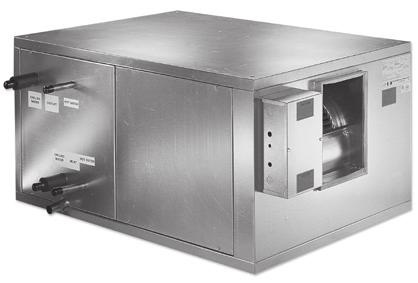
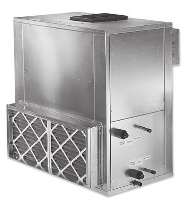
3 F2 Introduction: The flexibility of rueger s blower coil allows you to design the unit to meet specific project needs, including configurations for draw thru applications in horizontal, vertical, and footprintsaving arrangements. From basic applications to sophisticated isolation room systems required to meet challenging indoor air quality (IAQ), controls, and acoustic (sound sensitive) projects, rueger s is your solution. Constant Volume Applications: Two-pipe hydronic system for cooling and/or heating. Two-pipe hydronic cooling system with electric heat. Four-pipe system with dedicated heating and cooling coils. Direct expansion (DX) split systems with hydronic heat. Direct expansion (DX) split systems with electric heat. Variable Volume Applications: Two-pipe hydronic system for cooling and/or heating. Two-pipe hydronic cooling system with electric heat. Four-pipe system with dedicated heating and cooling coils. ODEL - odular lower Coil FEATURES odular construction allows for footprint saving arrangements including stacking modules in two-high configuration. IAQ galvanized drain pans are double sloped to prevent standing water and minimize microbial growth. Stainless steel drain pans are available. Removable access panels for improved accessibility, cleanability, and serviceability. Hinged access doors with quick action latches are available. Single point power connection even with draw thru or blow thru electric heat simplifies installation. Fan motors are factory mounted and wired to the junction box. Available in nine sizes, from 600 to 10,000 CF. Internal spring isolation standard on all unit sizes Single wall and double wall-galvanized construction are available. Double wall construction enhances indoor air quality, protects insulation, and provides the ability to clean the inside of the unit. OPTIONAL FEATURES Factory-packaged blower coil units are available with starters or variable frequency drives, factory mounted and wired. Simply connect power, piping, and ductwork, and the units are ready for operation. An excellent way to minimize installation time, coordination and costs, while increasing reliability. Quiet, flexible, acoustical discharge plenums may be used for sound sensitive projects. Customized options including: - Direct Drive Plenum Fans - High Efficiency Filters - Double Wall Perforated Lining F2-46 FOR - C.D /05/14
4 F2 Product Description ACOUSTICS Control of noise within both occupied and unoccupied spaces has become increasingly important to designers and building owners / occupants. Proper consideration must be given to placement of indoor air conditioning units, particularly in the occupied space. Inherent flexibility of the fan and coil combination in the vertical configuration allows application in sound-sensitive areas. In such instances, a fan running at low speed with a high capacity coil normally yields satisfactory results. It also may be desirable to select a larger nominal capacity unit and operate it at a less than nominal airflow for further acoustic benefit. Three phase motors are recommended for soundsensitive applications to avoid potential single phase motor hum. Unit operation in the stall region of the fan curve is not recommended since it may cause unsatisfactory noise levels and excessive unit vibration. INSTALLATION These floor mounted or ceiling hung units can be installed on a base rail or hanger rods at the corner points. All units have internally isolated fan decks; therefore, flex connections are not required, which will reduce installation costs. One of the most important and basic IAQ issues is condensate management. The first step to ensure trouble-free operation is proper installation. It is very important that the unit be mounted high enough so that the condensate drain from the unit may be properly trapped. Please refer to the IO manual at for specifics on this issue. As with all HVAC systems, these units should be installed according to all applicable ASHRAE standards, SACNA, and local code requirements. OPERATING LIITATIONS Units must not be operated above maximum fan speed or unit airflow as listed in the fan performance section of this catalog. Unit operation at greater than maximum fan speed could drastically reduce bearing life and may result in a catastrophic failure. Operating at greater than the maximum allowable airflow in the cooling mode may result in unsatisfactory operation due to moisture carry over from the coil. In addition, it is often not economical to operate a unit at its maximum fan speed due to the greater motor power requirements. DESIGNED FOR AXIU FLEXIILITY rueger s model is designed to maximize flexibility of selection and installation. The unit is also designed to exceed the stringent quality standards of the institutional market, while remaining cost competitive in the light commercial segment of the market. rueger s model sets the new standard for quality, flexibility, and competitive pricing. OPTIONAL COPONENTS EAN FLEXIILITY The extensive variety of standard options available on the is where you find the versatility to fit any HVAC system designer s needs. Options include mixing boxes with standard low leak dampers, high efficiency filter sections for a 2 prefilter and 4 final filter, and blow thru electric heat with single point power connection. All electric heat units are listed with ETL as an assembly and carry the cetl label. High efficiency motors, starters, disconnects, and fusing mean easier coordination between mechanical and electrical trades. Coil options allow for 4 or 6 row cooling coils. Water coils have optional circuiting that can be used to reduce water pressure drop, which may also allow for pipe size reductions and lower material cost. Hot water or standard steam coils may be placed in the preheat or reheat position. All units have the option of foil faced insulation. LOWER INSTALLED COST odel blower coils are shipped completely assembled, reducing field installation time and labor. All units are thoroughly inspected and tested prior to shipment, eliminating potential problems at startup. otor wiring is brought to a junction box on the outside of the unit casing, reducing electrical hook-up time. A wide variety of fan discharge configurations allow for increased flexibility and easier installation on the jobsite, resulting in cost reductions by eliminating expensive elbows, etc. Units with electric heat should not be operated with leaving air temperature greater than 104 F, to prevent excessive leaving air temperatures and electric heat limit trips. A hydronic (or steam) coil and electric heat should not be operated simultaneously to prevent excessive leaving air temperatures and limit trips. Electric heat units are equipped with a lockout switch that disables the electric heater if the temperature of the hydronic (or steam) coil is greater than 104 F (40 C). Water coils must not be operated above a fluid velocity of 8 ft./sec. to reduce the possibility of velocity induced erosion and flow noise. Water coils must not be operated below a fluid velocity of 1 ft./sec. to prevent degraded coil performance caused by laminar flow. These high or low fluid flow rates may not be included in the AHRI coil certification. FOR - C.D /05/14 QUALITY PRODUCT units are built from G60 minimum spangled galvanized steel with a chromate coating. This metal surpasses the AST 125 hour salt spray test for corrosion and rust. Standard insulation is 1 inch fiberglass insulation which is glued and pin spotted for maximum positive adhesion. Insulation complies with UL 181 and NFPA 90A. All units, with or without electric heat, are ETL listed and labeled. All wiring is in compliance with NEC, assuring safety and quality for the owner Providing You With Air Distribution Solutions F2-47
5 F2 Product Description STANDARD FEATURES Construction odular design facilitates retrofit. Galvanized steel cabinet construction. 1 thick fiberglass insulation, glued and pinned in place. Gasketed, removable access panels sized for easy handling. Left and right hand arrangement. Access panels on all sections. Fan Assembly Single forward-curved fan sections. Statically and dynamically balanced. Solid steel shafting. all bearings with a minimum design average life (L50) of 100,000 hours. Fan decks with internal vibration isolation. Fan otor and Drive Single speed ODP motors RP single speed, 60 Hz. Single phase motors with inherent thermal protection. Three phase motors. Standard cross section v-belt drive with 1.2 service factor. Adjustable pitch motor pulley and fixed pitch blower pulley. Coils 1/2 O.D. seamless copper tubes. G60 steel coil casings. Collared aluminum fins. anual air vent plug on all water coils. 300 PSIG working pressure at 200 F. Copper OD sweat connections tube wall on water and evaporator coils tube wall on steam coils. OPTIONAL FEATURES Construction Double wall (solid or perforated) cabinets. Stainless steel IAQ drain pan with stainless steel male pipe threaded connection. ultiple fan discharge arrangements. Scrim reinforced foil faced insulation. Hinged access panels with lift and turn fasteners. 4 ase rails with rigging slots factory assembled and installed. Fan otor and Drive Direct drive plenum fans with inter- nal rubber-in-shear (RIS) isolation. TEFC motors. High efficiency motors. Two-speed motors with contactors. Variable frequency drives, factory installed (mounted & wired). otor starter (contactor with overload for three phase; contactor for single phase), factory installed (mounted & wired). Return FC and plenum fan sections. Coils 3, 4, 6 and 8 row chilled water or DX coils. Up to 4 rows hot water or up to 2 rows standard steam. Heating coil in preheat or reheat position. Coil connections opposite handing. Stainless steel coil casings tube wall thickness. Auto air vents. Filters and Filter Rack 4 high efficiency pleated filters (65, 85, and 95%). ixing box with filter sections (flat or v-bank filter arrangements). Filters and Filter Rack Hinged side access flat filter rack. 2 pleated filters (30%). Electrical Fan motor wired and terminated to junction box. All units cetl listed in compliance with UL/ANSI Electric Heat Section Draw thru or blow thru configurations. Factory mounted electric heater with single point power connection, ETL listed as an assembly. Inlet Damper Section Factory assembled and installed. Heavy gage galvanized steel formed blade dampers. Low leak dampers with extruded vinyl blade seals and flexible metal jamb seals. edium and large inlet plenums with v-bank or flat filters. Parallel blade operation. I nterconnecting damper linkage. Damper actuator (modulating from 100% OA to 100% RA). Additional odules Discharge plenums. Access sections. F2-48 Electrical otor wiring in conduit. Single or three phase fan control packages. Door interlocking disconnect switch (non-fused or fused). Fusing (main or per stage). Hand off auto switch (HOA). Frequency inverters. Electric heat interlock relay. Relays, transformers, etc. FOR - C.D /05/14
6 F2 Static Pressure Data SECTION PRESSURE DROPS Unit Size CF ixing ox F LF L Economizer Fan odules HE FC RF VF Component Air Pressure Drop ( WG) Cabinet Losses Filter odules SF V Coil odules SC C VC Access odules Plenum odule Damper Losses ixing ox Economizer Electric Heater Losses NOTES: Figures do not include pressure drop of internal filter media. Refer to air pressure drop through filter section table for filter air pressure drop adders. Figures do not include pressure drop of internal heating and/or cooling coils. Refer to air pressure drop through dry coil section table for coil air pressure drop adders. ixing box with single damper in fully opened position operating at 100% air volume. Economizer with outside air and exhaust dampers in fully opened position operating at 100% air volume. SA A LA LP F LF L low Thru Draw Thru HE EH EHD FOR - C.D /05/14 Providing You With Air Distribution Solutions F2-49
7 F2 Coil and Filter Information COILS rueger offers hot water, chilled water, direct expansion (DX), and standard steam coils for specific application with all blower coils. Coils tested in accordance with AHRI 410, and strict on-site inspection before, during, and after installation guarantees the highest quality and performance available. STANDARD FEATURES All coils are designed, manufactured and tested by rueger. 1/2 O.D. seamless copper tubes. Aluminum fin construction with die-formed spacer collars for uniform spacing. echanically expanded copper tubes leak tested to a minimum 350 PSIG air pressure under water. anual air vent plug on all water coils. Copper OD sweat connections PSIG working pressure at 200 F. Refrigerant coils are factory sealed and charged with a minimum of 5 PSIG nitrogen or refrigerated dry air. Refrigerant coils are provided with a fixed orifice distributor. Thermal expansion valves are not included. Steam coils rated at maximum for 15 PSIG tube wall thickness (0.025 on steam). OPTIONAL FEATURES Stainless steel coil casings. Automatic air vents on water coils. Elevated working pressure ratings. Heat pump compatible cooling coils. Double circuit DX coils (50-50 split) tube wall thickness. COIL AND FILTER INFORATION Unit Sizes Coil Face Area Flat Filters V-ank Filters Quantity Dimensions Face Area Quantity Dimensions Face Area [0.20] 1 16 x20 x2 (406x508x51) 2.2 [0.20] 2 16 x20 x2 (406x508x51) 4.4 [0.41] [0.27] 1 16 x25 x2 (406x635x51) 2.8 [0.26] 2 16 x25 x2 (406x635x51) 5.6 [0.52] [0.35] 2 16 x20 x2 (406x508x51) 4.4 [0.41] 2 20 x25 x2 (508x635x51) 6.9 [0.64] [0.52] 2 20 x25 x2 (508x635x51) 6.9 [0.64] 4 20 x20 x2 (508x508x51) 11.1 [1.03] [0.69] 2 20 x25 x2 (508x635x51) 6.9 [0.64] [0.90] x25 x2 (406x635x51) 20 x25 x2 (508x635x51) 9.7 [0.90] x20 x2 (406x508x51) 20 x25 x2 (508x635x51) 16 x20 x2 (406x508x51) 20 x20 x2 (508x508x51) 11.4 [1.06] 15.6 [1.45] [1.17] 4 20 x25 x2 (508x635x51) 13.9 [1.29] 6 20 x25 x2 (508x635x51) 20.8 [1.93] [1.33] 8 16 x20 x2 (406x508x51) 17.8 [1.65] x25 x2 (508x635x51) 20 x20 x2 (508x508x51) 27.1 [2.52] [1.58] 6 20 x25 x2 (508x635x51) 20.8 [1.93] x20 x2 (508x508x51) 33.3 [3.09] NOTES: Standard filters are 2 throwaway; optional filters are 2 pleated. Filter sizes are nominal and standard size, measured in inches (millimeters). Coil and filter face areas are measured in square feet [square meters]. Cooling and heating coils have same face area. For coil connection sizes, refer to the rueger s selection program. F2-50 FOR - C.D /05/14
8 F2 Filter and Coil Pressure Data FILTER PRESSURE DROPS Filter Type High Efficiency Pleated Size & Efficiency Air Velocity (FP) % % % % NOTES: Figures listed represent air pressure drop of clean filters. Usable pressure drop across pleated media not recommended to exceed 1.0 w.g. Air velocities associated with pressure drops in the dark shaded region are not recommended. COIL PRESSURE DROPS Rows Fins per Inch AIR PRESSURE DROP THROUGH DRY COIL SECTION ( WG) Air Velocity (FP) NOTES: Dehumidifying cooling coils with face velocities exceeding 525 fpm are not recommended. FOR - C.D /05/14 Providing You With Air Distribution Solutions F2-51
9 F2 Coil Weight Information COIL WEIGHTS Unit Size Coil Rows Dry Coil 100% Water 40% Glycol 8 FPI 10 FPI 12 FPI 14 FPI 8 FPI 10 FPI 12 FPI 14 FPI 8 FPI 10 FPI 12 FPI 14 FPI 1 10 [5] 11 [5] 11 [5] 11 [5] 12 [5] 12 [5] 13 [6] 13 [6] 12 [5] 12 [5] 13 [6] 13 [6] 2 16 [7] 16 [7] 17 [8] 18 [8] 19 [9] 20 [9] 21 [10] 21 [10] 20 [9] 20 [9] 21 [10] 22 [10] 3 21 [10] 22 [10] 23 [11] 24 [11] 27 [12] 28 [13] 29 [13] 30 [14] 27 [12] 28 [13] 29 [13] 30 [14] 4 28 [13] 29 [13] 30 [14] 32 [14] 35 [16] 36 [16] 37 [17] 39 [18] 35 [16] 36 [16] 38 [17] 39 [18] 6 40 [18] 42 [19] 44 [20] 46 [21] 51 [23] 53 [24] 55 [25] 57 [26] 51 [23] 53 [24] 55 [25] 58 [26] 8 57 [26] 61 [28] 65 [30] 69 [31] 71 [32] 75 [34] 79 [36] 83 [38] 72 [33] 76 [34] 80 [36] 84 [38] 1 13 [6] 13 [6] 13 [6] 14 [6] 15 [7] 16 [7] 16 [7] 17 [8] 15 [7] 16 [7] 16 [7] 17 [8] 2 19 [9] 20 [9] 21 [10] 22 [10] 24 [11] 25 [12] 26 [12] 27 [12] 25 [11] 26 [12] 27 [12] 28 [13] 3 26 [12] 28 [13] 29 [13] 31 [14] 34 [15] 35 [16] 37 [17] 38 [17] 34 [15] 36 [16] 37 [17] 39 [17] 4 34 [15] 36 [16] 38 [17] 40 [18] 44 [20] 46 [21] 48 [22] 50 [23] 44 [20] 46 [21] 48 [22] 50 [23] 6 50 [23] 53 [24] 56 [25] 59 [27] 64 [29] 67 [31] 70 [32] 73 [33] 65 [20] 68 [31] 71 [32] 74 [34] 8 71 [32] 76 [34] 81 [37] 86 [39] 89 [41] 95 [43] 100 [45] 105 [47] 91 [41] 96 [43] 101 [46] 106 [48] 1 15 [7] 15 [7] 16 [7] 17 [8] 18 [8] 18 [8] 19 [9] 20 [9] 18 [8] 19 [9] 19 [9] 20 [9] 2 23 [11] 24 [11] 26 [12] 27 [12] 29 [13] 30 [14] 32 [15] 33 [15] 30 [13] 31 [14] 32 [15] 33 [15] 3 32 [14] 33 [15] 35 [16] 37 [17] 40 [18] 42 [19] 44 [20] 46 [21] 41 [19] 43 [19] 45 [20] 47 [21] 4 41 [19] 44 [20] 46 [21] 49 [22] 53 [24] 55 [25] 58 [26] 60 [27] 54 [24] 56 [25] 59 [27] 61 [28] 6 60 [27] 64 [29] 68 [31] 72 [33] 78 [35] 82 [37] 86 [39] 89 [41] 79 [36] 83 [38] 87 [39] 90 [41] 8 80 [36] 85 [38] 90 [41] 95 [43] 103 [47] 108 [49] 113 [51] 118 [54] 105 [47] 110 [50] 115 [52] 120 [54] 1 19 [9] 20 [9] 21 [10] 22 [10] 24 [11] 25 [11] 26 [12] 27 [12] 24 [11] 25 [11] 26 [12] 27 [12] 2 32 [14] 34 [15] 36 [16] 38 [17] 41 [19] 43 [20] 45 [20] 47 [21] 42 [19] 43 [20] 45 [20] 47 [21] 3 45 [20] 48 [22] 50 [23] 53 [24] 58 [26] 61 [28] 64 [29] 67 [30] 59 [27] 62 [28] 65 [29] 67 [30] 4 59 [27] 62 [28] 66 [30] 70 [32] 76 [35] 80 [36] 84 [38] 88 [40] 77 [35] 81 [37] 85 [39] 89 [40] 6 87 [39] 92 [42] 98 [44] 104 [47] 113 [51] 119 [54] 124 [56] 130 [59] 115 [52] 120 [55] 126 [57] 132 [60] [53] 125 [57] 133 [61] 142 [64] 152 [69] 160 [73] 169 [77] 177 [80] 155 [70] 163 [74] 171 [78] 179 [81] 1 23 [11] 25 [11] 26 [12] 27 [12] 30 [14] 31 [14] 32 [15] 33 [15] 30 [14] 31 [14] 32 [15] 34 [15] 2 40 [18] 43 [19] 45 [20] 48 [22] 52 [24] 54 [25] 57 [26] 59 [27] 53 [24] 55 [25] 58 [26] 60 [27] 3 57 [26] 61 [27] 64 [29] 68 [31] 75 [34] 78 [36] 82 [37] 86 [39] 76 [34] 79 [36] 83 [38] 87 [39] 4 75 [34] 80 [36] 85 [38] 90 [41] 98 [45] 103 [47] 108 [49] 113 [51] 100 [45] 105 [47] 110 [50] 115 [52] [50] 118 [54] 126 [57] 133 [60] 146 [66] 153 [69] 161 [73] 168 [76] 148 [67] 155 [70] 163 [74] 170 [77] [71] 169 [77] 182 [83] 195 [88] 204 [92] 216 [98] 229 [104] 241 [110] 207 [94] 219 [99] 232 [105] 245 [111] 1 28 [13] 30 [13] 31 [14] 33 [15] 36 [16] 37 [17] 39 [18] 40 [18] 36 [16] 38 [17] 39 [18] 41 [18] 2 48 [22] 51 [23] 54 [25] 57 [26] 63 [28] 66 [30] 69 [31] 72 [33] 64 [29] 67 [30] 70 [32] 73 [33] 3 68 [31] 73 [33] 77 [35] 82 [37] 90 [41] 95 [43] 99 [45] 104 [47] 91 [41] 96 [44] 101 [46] 106 [48] 4 89 [41] 96 [43] 102 [46] 108 [49] 119 [54] 125 [57] 131 [60] 138 [62] 120 [55] 127 [58] 133 [60] 139 [63] [60] 142 [64] 152 [69] 161 [73] 176 [80] 186 [84] 195 [88] 204 [93] 179 [81] 188 [85] 198 [90] 207 [94] [83] 197 [90] 212 [96] 226 [103] 241 [109] 255 [116] 270 [122] 284 [129] 244 [111] 259 [117] 273 [124] 288 [131] 1 35 [16] 37 [17] 39 [18] 42 [19] 45 [21] 48 [22] 50 [23] 52 [24] 46 [21] 48 [22] 50 [23] 52 [24] 2 62 [28] 66 [30] 70 [32] 74 [34] 81 [37] 86 [39] 90 [41] 94 [43] 83 [38] 87 [39] 91 [41] 95 [43] 3 88 [40] 94 [43] 101 [46] 107 [49] 118 [53] 124 [56] 130 [59] 137 [62] 119 [54] 126 [57] 132 [60] 139 [63] [53] 125 [57] 133 [60] 142 [64] 155 [70] 164 [74] 172 [78] 181 [82] 158 [72] 166 [75] 175 [79] 184 [83] [78] 186 [84] 199 [90] 211 [96] 231 [105] 244 [111] 257 [117] 270 [122] 235 [107] 248 [112] 261 [118] 274 [124] [106] 251 [114] 269 [122] 287 [130] 311 [141] 329 [149] 347 [157] 365 [165] 316 [143] 334 [151] 352 [160] 370 [168] 1 39 [18] 41 [19] 44 [20] 46 [21] 50 [23] 53 [24] 55 [25] 58 [26] 51 [23] 54 [24] 56 [25] 58 [26] 2 69 [31] 74 [33] 78 [36] 83 [38] 91 [41] 96 [43] 101 [46] 106 [48] 92 [42] 97 [44] 102 [46] 107 [49] 3 98 [45] 106 [48] 113 [51] 120 [55] 132 [60] 139 [63] 146 [66] 154 [70] 134 [61] 141 [64] 149 [67] 156 [71] [59] 140 [63] 149 [68] 159 [72] 174 [79] 184 [83] 194 [88] 203 [92] 177 [80] 187 [85] 197 [89] 206 [94] [88] 208 [94] 223 [101] 237 [108] 260 [118] 274 [124] 289 [131] 303 [138] 264 [120] 279 [126] 293 [133] 308 [140] [123] 295 [134] 318 [144] 341 [155] 359 [163] 382 [173] 405 [184] 428 [194] 365 [166] 388 [176] 411 [186] 434 [197] 1 45 [20] 48 [22] 51 [23] 53 [24] 58 [26] 61 [28] 64 [29] 67 [30] 59 [27] 62 [28] 65 [29] 68 [31] 2 79 [36] 85 [39] 91 [41] 97 [44] 106 [48] 112 [51] 117 [53] 123 [56] 108 [49] 113 [51] 119 [54] 125 [57] [52] 122 [56] 131 [59] 140 [63] 153 [69] 162 [73] 170 [77] 179 [81] 155 [71] 164 [74] 173 [78] 181 [82] [68] 162 [73] 173 [79] 185 [84] 203 [92] 214 [97] 226 [102] 237 [108] 206 [93] 217 [99] 229 [104] 240 [109] [102] 241 [109] 259 [117] 276 [125] 302 [137] 319 [145] 336 [153] 354 [160] 307 [139] 324 [147] 341 [155] 359 [163] [93] 206 [93] 206 [93] 206 [93] 309 [140] 309 [140] 309 [140] 309 [140] 315 [143] 315 [143] 315 [143] 315 [143] NOTES: Unit weight data is shipping weight in pounds [kilograms]. F2-52 FOR - C.D /05/14
10 F2 Dimensional Information UNIT CONFIGURATIONS, ANGLED VIEW L L L L W H W H W H W H L L L W H H H L W W W H 7 (178) 8 (203) UNIT CONFIGURATIONS, DIENSIONAL DETAILS odule Size Position easurements H / W / L H / W / L H / W / L H / W / L H / W / L H / W / L H / W / L H / W / L H / W / L EF External Flat Filters (2 ) 17 3/8 (441) 28 (711) 5 1/4 (133) 17 3/8 (441) 34 (864) 5 1/4 (133) 17 3/8 (441) 42 (1069) 5 1/4 (133) 26 3/8 (670) 42 (1069) 5 1/4 (133) 26 3/8 (670) 46 (1168) 5 1/4 (133) 26 3/8 (670) 56 (1422) 5 1/4 (133) 41 3/16 (1046) 64 (1626) 5 1/4 (133) 41 3/16 (1046) 68 (1727) 5 1/4 (133) 41 3/16 (1046) 80 (2032) 5 1/4 (133) SA SC SF Small Access Small Coil Small Flat Filters (2 and/or 4 Cartridge) 15 (381) 36 (914) 15 (381) 15 (381) 15 (381) 34 (864) 48 (1219) 15 (381) 34 (864) 58 (1473) 15 (381) 66 (1676) 15 (381) 70 (1778) 15 (381) 82 (2083) 15 (381) A C F I R V edium Access edium Coil ed. SARTRAC ix. ox w/flat Filters (2 ) ed. SARTRAC Inlet Plenum w/flat Filters (2 ) edium ixing ox with Flat Filters (2 ) edium Inlet Plenum with Flat Filters (2 ) edium V-ank Filters (2 ) 36 (914) 34 (864) 48 (1219) 34 (864) 58 (1473) 66 (1676) 70 (1778) 82 (2083) HF HP VC VF Horizontal FC Fan Horizontal Plug Fan Vertical Coil Vertical FC Fan 32 (813) 36 (914) 32 (813) 32 (813) 36 (914) 34 (864) 48 (1219) 36 (914) 34 (864) 58 (1473) 36 (914) 66 (1676) 40 (1016) 70 (1778) 40 (1016) 82 (2083) 40 (1016) LF LI L LR LP Lg. SARTRAC ix. ox w/v-ank Filters (2 ) Lg. SARTRAC Inlet Plenum w/v-ank Filters (2 ) Large ixing ox with V-ank Filters (2 ) Large Inlet Plenum with V-ank Filters (2 ) Large Discharge Plenum 42 (1067) 36 (914) 42 (1067) 42 (1067) 42 (1067) 34 (864) 48 (1219) 42 (1067) 34 (864) 58 (1473) 42 (1067) 66 (1676) 42 (1067) 70 (1778) 42 (1067) 58 (1473) 42 (1067) FC FC Fan and Coil Combination (Horizontal Only) 34 (864) 34 (864) EH Electric Heat low Thru 13 1/2 (343) 11 1/2 (292) 13 1/2 (343) 11 1/2 (292) 13 1/2 (343) 11 1/2 (292) 18 (457) 17 (432) 18 (457) 17 (432) 18 (457) 17 (432) 21 (533) 24 (610) 21 (533) 24 (610) 21 (533) 24 (610) NOTES: All dimensions are ± 1/4 (6mm). etric values are soft conversions. Section images are for identification of unit configuration only. See individual section submittal drawings at for details. Certain configuration rules apply; see selection program for details. FOR - C.D /05/14 Providing You With Air Distribution Solutions F2-53
11 F2 Electric Heat Features & Capacities ELECTRIC HEAT STANDARD FEATURES G60 galvanized steel casing. Flanged construction for direct unit mounting, in blow thru conguration. Listed for zero clearance installation. eets National Electrical Code requirements. Ni-Chrome wire in ceramic insulators. Stainless steel element terminals and hardware. Element support brackets on maximum 3 1/2 centers. Solid cover with continuous full height hinge. Over-temperature protection. All internal wiring rated for 105 C minimum. Airflow switch. Incoming line power distribution block. ETL Listed in compliance with UL/ANSI Standard Single point power connection. Heater factory mounted to unit with ETL listing as an assembly. OPTIONAL HEATER CONTROL ain incoming power disconnect (non-fused) (fused). Fusing (main) (per stage). agnetic contactors wired for disconnecting operation. Solid state relay with 4-20 ma, thermistor Ohm, 0-16 VDC, or 6-9 VDC control. Fan control package with heater interlock contacts (required for single point power connection). De-rated elements (for longer life). LOW THRU (INSTALLED ON UNIT DISCHARGE) DRAW THRU (INSTALLED UPSTREA OF FAN) AIRFLOW SIDE VIEW FRONT VIEW HEATER AP CALCULATION Voltage APs per kw 115 / / / / / / / / 3 PLAN VIEW SIDE VIEW AIRFLOW NOTES: Non-fused door interlock disconnect switch shall be sized according to CA. Fused door interlock disconnect switch and main fusing shall be sized according to OP. Heaters above 480v must utilize one time secondary limits only. F2-54 FOR - C.D /05/14
12 F2 Electric Heat Features & Capacities LOW-THRU ELECTRIC HEAT kw LIITS Single Phase Three Phase Unit Voltage and Phase Unit Size in ax in ax in ax in ax in ax in ax in ax in ax in ax kw APs kw APs kw APs kw APs kw APs kw APs kw APs kw APs NOTES: low thru heaters can have a maximum of two stages. VFD controllers cannot be supplied with blow thru heaters. Specific kw ratings are available within the ranges shown; refer to rueger s selection program. Heaters above 480v must utilize one time secondary limits only. DRAW-THRU ELECTRIC HEAT kw LIITS Single Phase Three Phase Unit Voltage and Phase Unit Size in ax in ax in ax in ax in ax in ax in ax in ax in ax kw APs kw APs kw APs kw APs kw APs kw APs kw APs kw APs NOTES: Draw thru heaters can have a maximum of four stages. All heaters that have an AP draw greater than 48 APs will have a minimum of two stages. Specific kw ratings are available within the ranges shown; refer to rueger s selection program. Heaters above 480v must utilize one time secondary limits only. FOR - C.D /05/14 Providing You With Air Distribution Solutions F2-55
13 F2 otor & Electrical Information OTOR/DRIVE WEIGHT DATA otor Type otor Horsepower 1/3 1/2 3/ / / ODP 25 [11] 28 [13] 30 [762] 35 [16] 45 [20] 35 [16] 75 [34] 100 [45] 125 [57] 125 [57] 220 [100] TEFC 28 [13] 35 [16] 33 [338] 45 [20] 65 [29] 70 [32] 85 [39] 105 [48] 145 [66] 160 [73] 295 [134] E+ N/A N/A N/A 40 [18] 55 [25] 55 [25] 90 [41] 100 [45] 145 [66] 130 [59] 300 [136] 2 Speed 45 [20] 35 [16] 33 [338] 45 [20] 40 [18] 70 [32] 75 [34] N/A N/A N/A N/A NOTES: Includes motor, pulleys, belts, and motor base. otor/drive weight data is shipping weight in pounds [kilograms]. OTOR ELECTRICAL DATA otor Type aximum otor Amperage Voltage 115/1 208/1 230/1 277/1 208/3 230/3 460/3 575/3 1/ / / / / NOTES: Actual motor nameplate APs may vary, but will not exceed values shown. Consult rueger for applications requiring special motors. ADDITIONAL NOTES Forward curved Fans (elt Drive) Consult rueger for applications at operating conditions not in the following table and curves. Fan motor voltage, fan rotation, and fan RP may require field setting/adjustment. Drive losses not included in fan performance table and curves. In direction of airflow, after fan discharge only LP (Large Plenum) and EH (Electric Heat low Thru) are available. Section will have internal isolation. Plenum Fans (Direct Drive) Consult rueger for applications at specific operating conditions. VFD s are recommended for operation and field balancing of units whether factory supplied and factory mounted, field supplied and factory mounted, or field supplied and field mounted. In direction of airflow, there must be space prior to the plug fan inlet. For sizes 02 through 06, the minimum requirement is either an SA (Small Access) or an C (edium Coil). For sizes 08-17, the minimum requirement is an A (edium Access). Section will have internal isolation. F2-56 FOR - C.D /05/14
14 F2 Fan Curves UNIT SIZE 2, FAN 09-04, CLASS I 25% W.O. 35% 45% 55% 65% 75% 85% 1.5 HP 1 HP 3/4 HP 1/ 1800 RP 1600 RP 2000 RP 2200 AX RP 95% RP FLOW RATE (100 S OF CF) UNIT SIZE 3, FAN 09-06, CLASS I 25% W.O. 35% 45% 55% 65% 75% FOR - C.D /05/ HP 1 HP 3/4 HP 1/ 1000 RP 800 RP RP 1400 RP 1600 RP 1800 RP 2000 RP 2200 AX RP FLOW RATE (100 S OF CF) Providing You With Air Distribution Solutions F % 95%
15 F2 Fan Curves UNIT SIZE 4, FAN 10-07, CLASS I % W.O. 35% 45% 55% 65% HP 1 HP 3/4 HP 600 RP 800 RP 1000 RP 1800 RP 1600 RP 1400 RP 1200 RP 2000 AX RP % 85% 95% FLOW RATE (100 S OF CF) UNIT SIZE 6, FAN 12-09, CLASS I 25% W.O. 35% 45% 55% 65% 75% 1 HP 1.5 HP 3/4 HP 1000 RP 1200 RP 1400 RP 1600 RP 1800 AX RP 85% 95% 600 RP 800 RP FLOW RATE (100 S OF CF) F2-58 FOR - C.D /05/14
16 F2 Fan Curves UNIT SIZE 8, FAN 12-12, CLASS I 25% W.O. 35% 45% 55% 65% 5 HP 1.5 HP 1 HP 1000 RP 1200 RP 1400 RP 1700 AX RP 75% 85% 95% 600 RP 800 RP FLOW RATE (100 S OF CF) UNIT SIZE 10, FAN 15-11, CLASS I FOR - C.D /05/ % W.O. 35% 45% 55% 65% HP 75% 5 HP 85% 95% RP 600 RP 800 RP 1000 RP 1200 RP 1400 RP 1600 AX RP FLOW RATE (100 S OF CF) Providing You With Air Distribution Solutions F2-59
17 F2 Fan Curves UNIT SIZE 12, FAN 18-13, CLASS I 25% W.O. 35% 45% 55% 65% 7.5 HP 5 HP 800 RP 1000 RP 1200 AX RP 75% 85% 95% 600 RP 400 RP FLOW RATE (1000 S OF CF) UNIT SIZE 12, FAN 18-13, CLASS II % W.O. 35% 45% 55% 65% 75% 7.5 HP 5 HP 800 RP 1000 RP 1200 RP 1478 AX RP 85% 95% 600 RP 400 RP FLOW RATE (1000 S OF CF) F2-60 FOR - C.D /05/14
18 F2 Fan Curves UNIT SIZE 14, FAN 18-18, CLASS I 25% W.O. 35% 45% 55% 65% 7.5 HP 5 HP 600 RP 800 RP 1000 RP 1200 AX RP 75% 85% 95% 400 RP FLOW RATE (1000 S OF CF) UNIT SIZE 14, FAN 18-18, CLASS II FOR - C.D /05/ % W.O. 35% 45% 55% 65% 75% 7.5 HP 85% 5 HP 95% RP 600 RP 800 RP 1000 RP 1200 RP 1450 AX RP FLOW RATE (1000 S OF CF) Providing You With Air Distribution Solutions F2-61
19 F2 Fan Curves UNIT SIZE 17, FAN 18-18, CLASS I 25% W.O. 35% 45% 55% 65% 10 HP 7 1/ 5 HP 400 RP 600 RP 800 RP 1000 RP 1200 AX RP 75% 85% 95% FLOW RATE (1000 S OF CF) UNIT SIZE 17, FAN 18-18, CLASS II F HP 10 HP 7.5 HP 5 HP 400 RP 25% W.O. 35% 45% 55% 65% 600 RP 800 RP 1000 RP 1200 RP 1450 AX RP FLOW RATE (1000 S OF CF) 75% 85% 95% FOR - C.D /05/14
20 F2 Fan Curves UNIT SIZE 2, FAN , CLASS I % W.O. 50% 60% 70% 80% HP 1 HP 3/4 HP 1/ 3620 AX RP 90% FLOW RATE (100 S OF CF) UNIT SIZE 3, FAN , CLASS I FOR - C.D /05/ % W.O. 50% 60% 70% 80% 1.5 HP 90% 1 HP 3/4 HP 1/ AX RP FLOW RATE (100 S OF CF) Providing You With Air Distribution Solutions F2-63
21 F2 Fan Curves UNIT SIZE 4, FAN , CLASS I HP 1 HP 3/4 HP 1/ 40% W.O. 50% 60% 70% 3620 AX RP 80% 90% FLOW RATE (100 S OF CF) UNIT SIZE 6, FAN , CLASS I F % W.O. 50% 60% 70% 80% 2600 AX RP 90% 1.5 HP 1 HP 3/4 HP 1/ FLOW RATE (100 S OF CF) FOR - C.D /05/14
22 F2 Fan Curves UNIT SIZE 8, FAN , CLASS I % W.O. 50% 60% 70% HP 1.5 HP 1 HP 3/4 HP 1/ 2200 AX RP 80% 90% FLOW RATE (100 S OF CF) UNIT SIZE 10, FAN , CLASS I FOR - C.D /05/ % W.O. 50% 60% 70% % 7.5 HP 5 HP 90% 1.5 HP 1 HP 3/4 HP 1/ AX RP FLOW RATE (100 S OF CF) Providing You With Air Distribution Solutions F2-65
23 F2 Fan Curves UNIT SIZE 12, FAN , CLASS I 40% W.O. 50% 60% 70% 1.5 HP 1 HP 3/4 HP 1/ 5 HP 7.5 HP 1800 AX RP 80% 90% FLOW RATE (100 S OF CF) UNIT SIZE 17, FAN , CLASS % W.O. 50% 60% 70% 10 HP 7.5 HP 5 HP 1.5 HP 1 HP 3/4 HP 1/ 1800 AX RP 80% 90% FLOW RATE (100 S OF CF) F2-66 FOR - C.D /05/14
24 F2 Performance Data FORWARD CURVED FAN PERFORANCE DATA TSP WG Unit Size Actual CF RP HP RP HP RP HP RP HP RP HP RP * HP * RP * * * * * 790 * * * * HP * * * * * 0.24 * * * * TSP WG Unit Size Actual CF RP HP RP HP RP HP RP HP RP HP RP * * * * HP * * * * RP 690 * * * * 670 * * * * * * * * * HP 0.42 * * * * 0.54 * * * * * * * * * TSP WG Unit Size Actual CF RP HP RP HP RP HP RP HP RP HP RP * * * HP * * * RP 420 * * * * * * * 450 * * * * HP 0.63 * * * * * * * 1.01 * * * * NOTES: *Contact rueger. FOR - C.D /05/14 Providing You With Air Distribution Solutions F2-67
25 F2 Suggested Specification & Configuration GENERAL HVAC Guide Specifications: Size Range: ,000 CF odel: lower Coil Unit PART 1 GENERAL 1.01 System Description A. Indoor mounted blower coil unit designed to provide air to a conditioned space as required to meet specified performance requirements for ventilation, heating, cooling, filtration and air distribution. Unit shall be assembled for draw thru application and shall be arranged to discharge conditioned air horizontally or vertically as shown on the contract drawings.. Unit with a direct-expansion cooling coil shall have the capability to be used in a refrigerant circuit in conjunction with a field supplied and matched air-cooled condensing unit Quality Assurance A. Coils shall be tested in accordance with AHRI 410 Standard for Forced-Circulation Air-Cooling and Air-Heating Coils.. Direct expansion coils shall be designed and tested in accordance with ANSI/ASHRAE 15 Safety Code for Refrigeration Systems. C. Insulation and insulation adhesive shall comply with NFPA 90A and 90 requirements for flame spread and smoke generation. D. Unit shall be constructed in accordance with UL 1995 standards, comply with NEA standards and shall carry the cetl label, display certification symbol on units of certified models. Installation of ancillary electrical components shall comply with NEC Delivery, Storage and Handling Unit shall be stored and handled in accordance with the unit manufacturer s instructions. PART 2 PRODUCTS 2.01 Equipment F2-68 A. General Factory assembled blower coil unit that is modular in design and construction. Unit may consist of a fan and coil section with factory-installed chilled water or direct expansion coil, preheat or reheat coil, heating coil section, filter section, combination filter/mixing box (flat or V-bank arrangement), economizer, or access section(s) as indicated on the equipment schedules.. Unit Cabinet 1. Unit panels shall be constructed of G60 galvanized steel and shall be capable of withstanding 125-hour salt spray test per AST Standard 117. All casing panels shall be removable for easy access to the unit. All panels shall be gasketed to ensure a tight seal. 2. Double wall unit panels (includes corner posts, mullions and access doors) shall be 1 nominal thickness using 1.5-lbs/ft 3 fiberglass insulation between galvanized steel panels. 3. Single wall unit panels shall be 1 nominal thickness using matte-faced fiberglass insulation with a nominal density of not less than 1.5-lbs/ft Insulation shall be secured to casing with water based adhesive and weld pins where necessary, corresponding to 25/50-flame spread/smoke developed. 5. Condensate drain pans shall be sloped to prevent standing water and shall be constructed of 18 gage G60 galvanized steel or stainless steel; they shall have a galvanized steel or stainless steel male pipe threaded drain connection. C. Fan Section 1. Fan sections shall be constructed of G60 steel and shall have a formed channel base for integral mounting of fan, motor, and casing panels. Fan housing, wheel, shaft, and bearings shall be rigidly secured to the base unit. 2. Fan decks shall be internally spring isolated (one-inch deflection) with the fan outlet connection to be made using canvas duct. 3. Each unit shall have one fan wheel and housing only. FOR - C.D /05/14
26 F2 Suggested Specification & Configuration FOR - C.D /05/14 4. Fan wheels shall be designed for continuous operation at the maximum rated fan speed and motor horsepower. Fan wheels and shafts shall be selected to operate at least 25% below the first critical speed, and shall be statically and dynamically balanced as an assembly. 5. Fan shafts shall be solid steel, turned, ground and polished. 6. Fan bearings shall be a self-aligning, non-regreasable ball bearing type selected for an average life (L50) of 100,000 hours at design operation conditions, per ANSI Code Fan motor shall be mounted within the fan section casing. otor shall be NEA Design with sizes and electrical characteristics as shown on the equipment schedule. 8. Fan drive shall be designed for a minimum of 1.15 service factor and shall be factory mounted and aligned. elt drive package shall be variable-pitch type (constant volume) or fixed-pitch type (variable volume). D. Coil Sections 1. All coils shall have aluminum plate fins mechanically bonded to 1/2. OD seamless copper tubes by mechanical expansion. Coils shall be factory leak tested at 350-psig air pressure under water. Copper tubes shall be either or copper tube wall thickness. Coils shall have G60 galvanized steel or stainless steel casings with copper headers and sweat connections. 2. Chilled water coils shall have a working pressure of 300 psig at 200 F. No turbulence-promoting devices will be permitted inside the tubes. Headers shall have vent connections. 3. Direct-expansion coils shall be provided with pressure-type brass distributors with solder-type connections. Coils shall be designed and tested in accordance with ANSI/ASHRAE Hot water coils shall have a working pressure of 300 psig at 200 F. No turbulence-promoting devices will be permitted inside the tubes. Headers shall have vent connections. 5. Steam distributing coils (standard single tube type) shall have a maximum working pressure of 15 psig at ambient temperatures above 35 F. Tube wall thickness shall be as standard. 6. Electric heat coils for use in blower coil units shall be open coil type, nichrome wire resistance elements, insulated by floating ceramic bushings. Thermal cutouts for primary and secondary over-temperature protection shall be provided to meet UL and NEC requirements. aximum element watt density shall be 55-watts/sq inch. The manufacturer shall furnish an integral control box. It shall contain primary and secondary control thermal cutouts, relays, airflow switch, and fused control transformer. E. Filter Sections 1. Each filter section shall be designed and constructed to house the specific type of filter specified on the equipment schedule. 2. Flat filter sections shall accept 2, 30% (ERV-6) pleated filters of standard sizes. Sections shall include side access slide rails. Flat filter section shall be arranged with minimum depth in direction of airflow. 3. Angle filter section shall accept 2, 30% (ERV-6) pleated filters of standard sizes arranged in horizontal V formation. Sections shall include side access slide rails. F. Damper Sections 1. ixing boxes, filter mixing boxes and economizers shall have parallel blade, interconnecting dampers. Damper blades shall have parallel bends for stiffness and shall be mechanically fastened to steel rods rotating in brass bushings and mounted in rigid galvanized steel frames. Dampers shall be sectionalized to limit blade width, minimize blade deflection, and ensure tight closure. 2. All dampers for mixing boxes and filter mixing boxes shall be rated with a leakage rate not to exceed 5% of air quantity calculated at 2000 fpm velocity though damper and 4.0-in.wg. pressure difference. Damper blades shall be gasketed and stainless steel perimeter-sealing strips shall be provided. Damper linkage shall be provided and installed with all mixing boxes. G. Access Sections 1. Access sections shall be installed where indicated on the drawings and shall be as specified on the equipment schedule. 2. Access sections shall have removable access panels. H. Special Features The following unit options shall be available. 1. Fan Section: a. Variable frequency drives (VFD). Providing You With Air Distribution Solutions F2-69
SBH / SBV Sales Guide BLOWER-COILS HORIZONTAL AND VERTICAL
 SO TOUGH, WE GUARANTEE IT. SBH / SBV Sales Guide BLOWER-COILS HORIZONTAL AND VERTICAL SBH SBV www.superiorrex.com SO TOUGH, WE GUARANTEE IT! www.superiorrex.com SBH / SBV Series: CONSTRUCTION FEATURES
Submittal DIMENSIONS SIZE FAN SIZE L W H C D E F G J K [406] [508] 25 [635] [406] 16 [406] 16 [406] 39-1/2 [1003] 44-1/2 [1130] 51 [1295] 59 [1499]
![Submittal DIMENSIONS SIZE FAN SIZE L W H C D E F G J K [406] [508] 25 [635] [406] 16 [406] 16 [406] 39-1/2 [1003] 44-1/2 [1130] 51 [1295] 59 [1499]](/thumbs/94/122284584.jpg "Submittal DIMENSIONS SIZE FAN SIZE L W H C D E F G J K [406] [508] 25 [635] [406] 16 [406] 16 [406] 39-1/2 [1003] 44-1/2 [1130] 51 [1295] 59 [1499]") BC--1.0 03-01-1 Belt Drive Blower Coil Unit, Basic Unit Discharge ARGT. 1 4. See page 1 for filter rack details. 5. Base rail is optional on he base unit. See page 13. Base rails must be used with mixing
BC--1.0 03-01-1 Belt Drive Blower Coil Unit, Basic Unit Discharge ARGT. 1 4. See page 1 for filter rack details. 5. Base rail is optional on he base unit. See page 13. Base rails must be used with mixing
MQL TABLE OF CONTENTS
 MQL TABLE OF CONTENTS Product Overview...3 Features and Benefits...6 Application Considerations...5 Unit Configuration...6 Electric Heat...7 Coil and Filter Data...9 Static Pressure Data...10 Weight and
Horizontal and Vertical BELT DRIVE AIR HANDLING UNITS
 Horizontal and Vertical BELT DRIVE AIR HANDLING UNITS TABLE OF CONTENTS H & V Features and Benefits...4 Coil and Filter Data, Static Pressure Data...7 Electric Resistance Heat Section...8 Coil Information
Complete HVAC Capability
 Air Handling Units Brochure 1110 January 2006 Complete HVAC Capability MEA Horizontal Draw-Thru to Size 65 Vertical Draw-Thru to Size 50 1000 to 60,000 CFM Forward Curved or Airfoil Wheels Inlet Vane Option
The Premium Quality Fan Coil Units for Horizontal Application Hydronic or Electric Heat
 Producing Quality Heating & Cooling Equipment For Over 50 Years CEA SERIES CEILING EPOSED HORIZONTAL FAN COIL UNITS The Premium Quality Fan Coil Units for Horizontal Application Hydronic or Electric Heat
Product Data. Features/Benefits. 42BH System Fan Coil. 800 to 4000 Cfm
 Product Data 42BH System Fan Coil 800 to 4000 Cfm Satisfy All Your Design Requirements with Carrier s Versatile 42BH Fan Coil Unit A selection of 6 sizes covers capacities from 800 to 4000 cfm Choice of
SDL Single-Duct, Low-Height, VAV Terminals
 SDL -Duct, Low-Height, VAV Terminals SDL -Duct, VAV Terminals: Fit more comfort in less space Owners SDL terminals offer the typical benefits provided by single-duct units, while performing at extremely
TVS/R FAN COIL UNITS HI-RISE, VERTICAL
 TVS/R FAN COIL UNITS HI-RISE, VERTICAL TVRM TVRP Riser TVRS TVSE TVSM TVSR TVSS Redefine your comfort zone. www.titus-hvac.com Redefine your comfort zone www.titus-hvac.com Model TVS/R: CONCEALED, HI-RISE
VAHU Vertical Air Handling Unit
 500 to 5,400 CFM @ up to 6.00" TSP 2" double wall construction, perforated or solid lined 18 gauge G90 galvanized steel cabinet 4 standard cabinet sizes available Internally isolated direct drive plug
RAV Sales Guide FAN COIL UNITS HI-RISE, VERTICAL
 RAV Sales Guide FAN COIL UNITS HI-RISE, VERTICAL RAVS RARM RARS RAVE RAVM RAVL RARP RISER www.superiorrex.com RAV Series: VERTICAL HI-RISE CONCEALED SO TOUGH, WE GUARANTEE IT! www.superiorrex.com Model
FS Fan-Coil Units Hi-Rise, Vertical
 FS Fan-Coil Units Hi-Rise, Vertical FSC Concealed Dimensional Data 4-PIPE 2-PIPE TOP VIEWS Page Trims Short (5/8") Here! SIDE VIEW FRONT VIEW Dimensions Unit Size A B Single/Double Supply C D E 03 & 04
MODULAR SINGLE AND DOUBLE WALL BELT DRIVE AIR HANDLER DX OR CHILLED WATER COOLING HOT WATER OR ELECTRIC HEATING
 MODULAR SINGLE AND DOUBLE WALL BELT DRIVE AIR HANDLER DX OR CHILLED WATER COOLING HOT WATER OR ELECTRIC HEATING SIZES FROM 600 TO 9,000 All Technical Specifications are Subject to Change without Notice.
RBV Sales Guide FAN COIL UNITS FLOOR-MOUNTED, VERTICAL
 RBV Sales Guide FAN COIL UNITS FLOOR-MOUNTED, VERTICAL RBVS RBVR RBVC www.superiorrex.com RBV Series: LOW POWER CONSUMPTION, ACCESSIBLE AND FLEXIBLE Owners Owners can choose between a standard or elevated
TSS Single-Duct VAV Terminals
 TSS Single-Duct VAV Terminals Model TSS construction features Standard Construction Mechanical-lock construction ensures lowest possible casing leakage Roll-formed inlet collar with integral stiffening
MAH. Modular Air Handling Unit
 MA Modular Air andling Unit 500 to 11,000 CFM @ up to 6.00 TSP 2 and 4 double wall construction, perforated or solid lined 18 gauge G0 galvanized steel cabinet 26 standard cabinet sizes available Internally
VERTICAL SINGLE AND DOUBLE WALL BELT DRIVE AIR HANDLER DX OR CHILLED WATER COOLING WITH HOT WATER OR ELECTRIC HEAT
 VERTICAL SINGLE AND DOUBLE WALL BELT DRIVE AIR HANDLER DX OR CHILLED WATER COOLING WITH HOT WATER OR ELECTRIC HEAT SIZES FROM 600 TO 4,000 All Technical Specifications are Subject to Change without Notice.
B. Base occupied space sound level estimates on ARI 885. C. Terminal heating coils shall conform to ARI 410.
 PART 1 - GENERAL 1.01 Purpose: A. This standard is intended to provide useful information to the Professional Service Provider (PSP) to establish a basis of design. The responsibility of the engineer is
HORIZONTAL SINGLE AND DOUBLE WALL BELT DRIVE AIR HANDLER DX OR CHILLED WATER COOLING WITH HOT WATER OR ELECTRIC HEAT
 HORIZONTAL SINGLE AND DOUBLE WALL BELT DRIVE AIR HANDLER DX OR CHILLED WATER COOLING WITH HOT WATER OR ELECTRIC HEAT MADE IN USA SIZES FROM 600 TO 9,000 All Technical Specifications are Subject to Change
Climas y Proyectos Leyco, S.A. de C.V.
 GENERAL DESCRIPTION : FURNISH AND INSTALL MULTI COMPONENT ROOF MOUNTED LEYCO, MODEL CAH CUSTOM AIR HANDLER MADE SELF-CONTAINED, WEATHER RESISTANT, AIR HANDLING UNITS PER MODEL NUMBER, AND PERFORMANCE DATA
FAN POWERED TERMINAL UNITS
 Benefits: Fan powered terminals are typically used for heating and cooling of perimeter zones. Operating cost savings can be achieved through the use of waste heat recovery from the ceiling plenum and
MODULAR SINGLE AND DOUBLE WALL BELT DRIVE AIR HANDLER DX OR CHILLED WATER COOLING HOT WATER OR ELECTRIC HEATING
 MODULAR SINGLE AND DOUBLE WALL BELT DRIVE AIR HANDLER DX OR CHILLED WATER COOLING HOT WATER OR ELECTRIC HEATING MADE IN USA SIZES FROM 600 TO 9,000 All Technical Specifications are Subject to Change without
BVX SERIES VERTICAL DIRECT EXPANSION BLOWER COIL UNITS
 BVX SERIES VERTICAL DIRECT EXPANSION BLOWER COIL UNITS MAGIC AIRE BVX SERIES FAN COILS ARE ETLC LISTED IN ACCORDANCE WITH UL 1995 AND ARE ASSEMBLED TO ORDER FOR COMPETITIVE DELIVERY. UNITED ELECTRIC COMPANY,
ROOF TOP SINGLE AND DOUBLE WALL BELT DRIVE AIR HANDLER DX OR CHILLED WATER COOLING HOT WATER OR ELECTRIC HEATING
 ROOF TOP SINGLE AND DOUBLE WALL BELT DRIVE AIR HANDLER DX OR CHILLED WATER COOLING HOT WATER OR ELECTRIC HEATING MADE IN USA SIZES FROM 600 TO 9,000 All Technical Specifications are Subject to Change without
catalog SDL Single-Duct, Low-Height, VAV Terminals
 catalog SDL Single-Duct, Low-Height, VAV Terminals TABLE OF CONTENTS Features and Benefits.... 2 Controls.... 3 Construction Features... 4 Standard and Optional Features.... 5 Dimensional and Weight Data....
ATU PRODUCT CATALOG AIR TERMINAL UNITS FCI-600 CONSTANT VOLUME FAN TERMINAL UNIT Metal Industries, Inc.
 ATU PRODUCT CATALOG AIR TERMINAL UNITS FCI-600 CONSTANT VOLUME FAN TERMINAL UNIT 15 Metal Industries, Inc. BENEFITS: Fan powered terminals are typically used for heating and cooling of perimeter zones.
Electric Coil [Make-Up Air / Displacement Ventilation / Space Heating] System
![Electric Coil [Make-Up Air / Displacement Ventilation / Space Heating] System](/thumbs/89/99847795.jpg "Electric Coil [Make-Up Air / Displacement Ventilation / Space Heating] System") V-Series (rev. 08/17/10) Electric Coil [Make-Up Air / Displacement Ventilation / Space Heating] System Note: Optional items and/or items requiring a choice, are shown between brackets and/or parentheses
V-Series (rev. 08/17/10) Electric Coil [Make-Up Air / Displacement Ventilation / Space Heating] System Note: Optional items and/or items requiring a choice, are shown between brackets and/or parentheses
ELITE SERIES R-410A Ready - Multi-Position
 PRODUCT SPECIFICATIONS AIR HANDLERS CBXM ELITE SERIES R-0A Ready - Multi-Position Bulletin No. 0 October 07 Supersedes June 0 Nominal Capacity -. to Tons Optional Electric Heat -. to 0 kw MODEL NUMBER
RERV & RERVX RERVLP. Rotary Energy Recovery Ventilators. Low Profile Indoor Rotary Energy Recovery Ventilators
 Version: Dec. 01, 2004 RERV & RERVX Rotary Energy Recovery Ventilators Indoor and Outdoor Installations 250 20,000 CFM Capacities RERVLP Low Profile Indoor Rotary Energy Recovery Ventilators Ideal for
A I R H A N D L E R S CB26UH-R. MERIT Series R-22 - Upflow / Horizontal P R O D U C T S P E C I F I C AT I O N S
 P R O D U C T S P E C I F I C AT I O N S A I R H A N D L E R S CB6UH-R MERIT Series R- - Upflow / Horizontal Bulletin No. 1067 April 01 Supersedes January 01 Nominal Capacity - 1.5 to 5 Tons Optional Electric
catalog SDL Single-Duct, Low-Height, VAV Terminals
 catalog SDL Single-Duct, Low-Height, VAV Terminals Catalog: ET130.13-EG2 (708) TABLE OF CONTENTS Single-Duct, Low-Height VAV Terminals Features and Benefits....................... 2 Controls..................................
Dual Duct Variable Air Volume Terminal (Model TDS)
") Product Bulletin Issue Date June 21st, 2005 Dual Duct Variable Air Volume Terminal (Model TDS) Model TDS terminals provide Variable Air Volume (VAV) control beyond the typical dual duct box. They are specifically
Product Bulletin Issue Date June 21st, 2005 Dual Duct Variable Air Volume Terminal (Model TDS) Model TDS terminals provide Variable Air Volume (VAV) control beyond the typical dual duct box. They are specifically
FN Fan-Coil Units High-Performance, Horizontal
 FN Fan-Coil Units High-Performance, Horizontal Model FNX Exposed-Cabinet Dimensional Data Notes: 1. All dimensions are in inches [mm] and are +/- 1/8" [3 mm]. Metric values are soft conversions. 2. See
SINGLE DUCT TERMINAL UNITS
 www.igcaire.com SINGLE DUCT TERMINAL UNITS Direct Digital Control, Pressure Independent FEATURES 22 Gauge Galvanized Steel Casing Construction with a 20 Gauge Casing Option that Provides Strength and Product
Submittal 30 [762] 36 [914] 40 [1016] 50 [1270] 60 [1524] 70 [1778]
![Submittal 30 [762] 36 [914] 40 [1016] 50 [1270] 60 [1524] 70 [1778]](/thumbs/85/92244975.jpg "Submittal 30 [762] 36 [914] 40 [1016] 50 [1270] 60 [1524] 70 [1778]") FCU-THBP-1.0 08-22-18 THBP Horizontal Low Profile Plenum Return Top View (Drain Pan Omitted) Bottom View Front View Left hand unit shown. All dimensions are inches [millimeters]. Side View Unit Size A
FCU-THBP-1.0 08-22-18 THBP Horizontal Low Profile Plenum Return Top View (Drain Pan Omitted) Bottom View Front View Left hand unit shown. All dimensions are inches [millimeters]. Side View Unit Size A
FAN POWERED SERIES FCI-600 CONSTANT VOLUME FAN TERMINAL UNIT SPECIFIABLE FEATURES
 FAN TERMINAL UNIT SPECIFIABLE FEATURES Galvanized steel casing, mechanically sealed for low leakage construction NEMA TYPE 1 rated hinged control enclosure with standoff to prevent penetration of casing
Submittal. Front View Side View
 RBHO Horizontal Low Profile Concealed Free Return Submittal FCU-RBHO-1.0 07-25-18 Top View (Drain Pan Omitted) Bottom View Front View Side View Left hand unit shown. All dimensions are inches [millimeters].
FW and FL Fan-Coil Units Floor-Mounted, Vertical STANDARD AND LOW PROFILE
 FW and FL Fan-Coil Units Floor-Mounted, Vertical STANDARD AND LOW PROFILE Low Power Consumption, Accessible, & FW and FL Fan-Coil Design Features Owners Owners can choose between a standard height (FW)
NORTHWESTERN UNIVERSITY PROJECT NAME JOB # ISSUED: 03/29/2017
 SECTION 23 3600 - AIR TERMINAL DEVICES PART 1 - GENERAL 1.1 SUMMARY A. Section Includes: 1. Fan-powered air terminal units/devices. 2. Shut off air terminal units/devices. 3. Dual duct terminal units/devices.
Indoor Air Handling Unit (Model AMI)
") Technical Bulletin Issue Date December 15, 2004 Indoor Air Handling Unit (Model AMI) Model AMI Indoor Air Handling Units are designed to maximize flexibility of selection and installation, enabling you
Technical Bulletin Issue Date December 15, 2004 Indoor Air Handling Unit (Model AMI) Model AMI Indoor Air Handling Units are designed to maximize flexibility of selection and installation, enabling you
SECTION AIR TERMINAL UNITS
 SECTION 23 36 00 AIR TERMINAL UNITS PART 1 - GENERAL 1.1 SUMMARY A. Section includes constant volume terminal units, variable volume terminal units, dual duct terminal units, fan powered terminal units,
T VB FA N COIL U NIT S F LO OR -MOU NT E D, V E RT ICA L
 T VB FA N COIL U NIT S F LO OR -MOU NT E D, V E RT ICA L TVBA TVBC TVBF Redefine your comfort zone. www.titus-hvac.com Redefine your comfort zone www.titus-hvac.com Model TVB: LOW POWER CONSUMPTION, ACCESSIBLE
Horizontal and Vertical Belt Drive Blower Coil Units (Models AHI and AVI)
") Technical Bulletin Issue Date December 6, 2004 Horizontal and Vertical Belt Drive Blower Coil Units (Models AHI and AVI) Model AHI Horizontal and Model AVI Vertical Belt Drive Blower Coils are designed
Technical Bulletin Issue Date December 6, 2004 Horizontal and Vertical Belt Drive Blower Coil Units (Models AHI and AVI) Model AHI Horizontal and Model AVI Vertical Belt Drive Blower Coils are designed
FAN POWERED TERMINAL UNITS
 Benefits: Fan powered terminals are typically used for heating and cooling of perimeter zones. Operating cost savings can be achieved through the use of waste heat recovery from the ceiling plenum and
WE ARE PLEASED TO PROVIDE THE ENCLOSED SUBMITTAL FOR YOUR REVIEW AND APPROVAL
 PREPARED FOR: DATE: JOB NAME: WE ARE PLEASED TO PROVIDE THE ENCLOSED SUBMITTAL FOR YOUR REVIEW AND APPROVAL EQUIPMENT DETAILS ITEM TAG DESCRIPTION MODEL NUMBER 1 2 3 4 5 6 7 8 9 10 11 12 13 14 15 EQUIPMENT
42C/D SERIES Ducted Chilled Water Fan Coil Unit With District Cooling Application
 42C/D SERIES Ducted Chilled Water Fan Coil Unit With District Cooling Application MAXIMIZING PERFORMANCE, ENERGY SAVINGS & COMFORT MODEL NUMBER NOMENCLATURE 4 2 C E T 0 0 3 4 7 0 1 2 5 42 series CISB Code
RAH Engineering Guide
 FAN COIL UNITS FREE RETURN RAH Engineering Guide SO TOUGH, WE GUARANTEE IT. RAHC RAHO RAHR www.superiorrex.com Table of Contents Features and Benefits... 3 Construction Features... 4 Standard and Optional
Horizontal Fan Coils 200-1,200 CFM
 Horizontal Fan Coils 200-1,200 CFM Table of Contents Williams Fan Coils & Air Handlers..................................................... 1 Horizontal Models......................................................................
UNIVERSITY OF NORTH FLORIDA Arena HVAC Replacement SECTION MODULAR INDOOR CENTRAL-STATION AIR-HANDLING UNITS
 SECTION 23 73 13 MODULAR INDOOR CENTRAL-STATION AIR-HANDLING UNITS PART 1 - GENERAL 1.1 RELATED DOCUMENTS A. Drawings and general provisions of the Contract, including General and Supplementary Conditions.
FCVC Series VERTICAL FAN COILS
 VERTICAL FAN COILS The FCVC is designed for concealed, wall mounted installations with flexible heating/ cooling loads and minimal duct requirements. With a variety of options, such as fiber free insulation,
DESCRIPTION ACCESSORIES FIELD INSTALLED SPLIT-SYSTEM EVAPORATOR BLOWERS KBBU060, KDBC090, KCBC120 & KCBC180 5 THRU 15 NOMINAL TONS SUPPLY AIR PLENUMS
 DESCRIPTION TECHNICAL GUIDE SPLIT-SYSTEM EVAPORATOR BLOWERS KBBU060, KDBC090, KCBC120 & KCBC180 5 THRU 15 NOMINAL TONS These completely assembled units include a well-insulated cabinet, a DX cooling coil
Direct Gas-Fired Heating
 Direct Gas-Fired Heating Model DG 800 to 15,000 cfm Up to 1,600,000 BTU/hr Optional Evaporative Cooling January 2005 PRODUCT FEATURES Model DG Direct Gas-Fired Make-Up Air Unit The Greenheck model DG is
A Division of Nailor International Inc. ECONOMY AIR HANDLERS
 A Division of Nailor International Inc. MODEL : ECONOMY AIR HANDLERS Thermal Model Standard Specification MODEL 800-4000 CFM AIR HANDLERS Description Model air handlers are designed for efficient and economical
Product Data. 42D Ducted Fan Coil Air Conditioners cfm
 Product Data 42D Ducted Fan Coil Air Conditioners 600-2000 cfm Carrier s 42D series ducted fan coil units offer design and equipment location flexibility Choice of 5 models, each available in 8 sizes For
BAC / BHC Product Specifications
 COMMERCIAL AIR HANDLERS (3 PHASE) 6 to 20 TON / Product Specifications REFRIGERATION CIRCUIT Standard factory-installed thermostatic expansion valves (TXVs) on units; units include TXVs and check valves
42CET/ 42CED Series Chilled Water Fan Coil Unit Furred-in Ceiling Model 300 to 1400 cfm Electric heater option
 42CET/ 42CED Series Chilled Water Fan Coil Unit Furred-in Ceiling Model 0 to 10 cfm Electric heater option 42DC/ 42DCD Series Chilled Water Fan Coil Unit Furred-in Ceiling Model 0 to 00 cfm Electric heater
 Issue 4 (Record Only) Job #: Innovent Submittal Date: October 30, 2012 Project: Location: Columbus, OH Innovent Job #: Submittal Issue: 4 (Record Only) Engineer: Contractor: Tag Innovent Model # AHU-BG-01
SPLIT-SYSTEM EVAPORATOR BLOWER DESCRIPTION ACCESSORIES EER 8.5 ARI RATINGS* K2ES120A25 10 NOMINAL TONS WITH TWO 5 TON CIRCUITS
 550.13-TG11Y (0500) SPLIT-SYSTEM EVAPORATOR BLOWER K2ES120A25 10 NOMINAL TONS WITH TWO 5 TON CIRCUITS EER 8.5 DESCRIPTION This completely assembled dual circuit evaporator blower includes a well-insulated
technical sales guide - 60Hz Ducted Split Units HIGH AMBIENT OPERATION 52 UPTO
 technical sales guide - 60Hz Taurus R Ducted Split Units UPTO HIGH AMBIENT OPERATION 52 O C Page CONTENTS Nomenclature.. 2 Description. 3 Features.. 3 Product Data. 4 Condensing Unit Cooling Performance
Daikin McQuay. Large Capacity Fan Coil Belt Drive. HCBB, HHBB Design 1. Replacement Parts List No Revision E 03/2018
 Replacement s List No. 700024000 Revision E 03/2018 Daikin McQuay Large Capacity Fan Coil Belt Drive HCBB, HHBB 08-30 Design 1 To find your Daikin Applied parts distributor, call 1-800-377-2787 or visit
University of Delaware
 SECTION 23 36 00 _ SUMMARY PART 1 GENERAL 1.1 SUMMARY A. Section Includes: 1. Constant/Variable volume supply terminal units. 2. Fan powered terminal units. 3. Exhaust valves B. Related Sections: Section
D M S 760 C01 A A 1 1
 CONTENTS Description Features Options Available Selection Method Product Data Cooling Performance Data (85 F Ambient Cooling Performance Data (95 F Ambient) Cooling Performance Data (105 F Ambient)..............................
SPECIFICATIONS AND DESIGN ARE SUBJECT TO CHANGE WITHOUT PRIOR NOTICE. EDITION 11
 AIR HANDLING UNIT (DOUBLE SKIN) MODEL: DS-CW/DX-AHU-H (Chilled Water or Direct Expansion) CAPACITY: 3.3 to 125 Nominal Tons 39,000 to 1,500,000 BtuH 11.4 to 439.5 KW 1,300 to 50,000 CFM Benefits Horizontal
HBC SERIES-PSC MOTOR HBCX SERIES-ECM MOTOR
 PRODUCT SPECIFICATIONS *HBC(X) *PHBC(X) *RHBC(X) *CHBC(X) Chilled Water/Hot Water 2-pipe/4-Pipe HBC SERIES- HBCX SERIES-ECM MOTOR Ceiling Concealed Horizontal -1 CFM Ceiling Concealed Ceiling Recessed
SECTION AXIAL HVAC FANS
 SECTION 233413 - AXIAL HVAC FANS 1. PART 1 GENERAL 1.1. RELATED DOCUMENTS A. Drawings and general provisions of the Contract, including General and Supplementary Conditions and Division 01 Specification
MERIT Series R-410A - Upflow / Horizontal - Variable Speed
 PRODUCT SPECIFICATIONS AIR HANDLERS CBX5UHV (-01) MERIT Series R-10A - Upflow / Horizontal - Variable Bulletin No. 10611 March 015 Supersedes November 01 MODEL NUMBER IDENTIFICATION CB X 5 UH V - 00-0
INSTALLATION MANUAL TBH/TBV BELT DRIVE BLOWER-COIL UNITS HORIZONTAL. Redefine your comfort zone.
 INSTALLATION MANUAL TBH/TBV BELT DRIVE BLOWER-COIL UNITS HORIZONTAL BELT DRIVE BLOWER-COIL UNITS TBH/TBV, HORIZONTAL Table of Contents Safety Symbols & Considerations...3 Return / Exhaust Casing Extension...4
Daikin McQuay. Large Capacity Fan Coil Direct Drive. HCDB, HHDB Design 1. Replacement Parts List No Revision B 03/2016
 Replacement s List 70002400 Revision B 03/206 Daikin McQuay Large Capacity Fan Coil Direct Drive HCDB, HHDB 06-20 Design To find your Daikin Applied parts distributor, call -800-377-2787 or visit www.daikinapplied.com
Typical Applications. Horizontal Installation
 ENGINEERING DATA COILS COIL UNITS CB19 AND CBH19 SERIES UP-FLOW, DOWN-FLOW AND HORIZONTAL COIL UNITS *12,600 to 65,500 Btuh (3.7 to 19.2 kw) Cooling Capacity 11,500 to 60,000 Btuh (3.4 to 17.6 kw) Heat
Product Data. Features/Benefits. Omnizone 50XCA06-14 Air-Cooled Indoor Self-Contained Systems with Puron Refrigerant (R-410A) 5 to 12 Nominal Tons
 5 to 12 Nominal Tons") Product Data Omnizone 50XCA06-14 Air-Cooled Indoor Self-Contained Systems with Puron Refrigerant (R-410A) 5 to 1 Nominal Tons The 50XCA single-package cooling units with integral air-cooled condensers
Product Data Omnizone 50XCA06-14 Air-Cooled Indoor Self-Contained Systems with Puron Refrigerant (R-410A) 5 to 1 Nominal Tons The 50XCA single-package cooling units with integral air-cooled condensers
SINGLE PACKAGE AIR CONDITIONING WATER COOLED
 MODELS: CU060-300 5-25 TONS VERTICAL SINGLE PACKAGE AIR CONDITIONING WATER COOLED MODELS: CH060-5-10 TONS HORIZONTAL FOR DISTRIBUTION USE ONLY - NOT TO BE USED AT POINT OF RETAIL SALE TABLE OF CONTENTS
ELTAFANTECH Air Handling Unit 700 up to 42,000 CFM
 an ELTA GROUP company ELTAFANTECH 700 up to 42,000 CFM INNOVATIVE Design & Performance INTRODUCTION There are 24 standard sizes of optimally engineered s to handle air volumes from 700 CFM to 42,000CFM.
TECHNICAL GUIDE GENERAL SPECIFICATIONS COMMERCIAL SPLIT-SYSTEM COOLING UNITS FOUR PIPE SYSTEM OUTDOOR UNIT:
 036-21323-001-B-0202 GENERAL SPECIFICATIONS OUTDOOR UNIT: Two independent refrigerant circuits Inherently protected fan motors Two independent scroll compressors V-Coil Design Exterior service port connections
500-YVI PARALLEL FAN-POWERED AIR TERMINAL UNIT FORM EG3 (404)
") 500-YVI PARALLEL FAN-POWERED AIR TERMINAL UNIT Table of Contents Introduction...3 500-YVI Features...4-5 Dimensional Data...6-7 ARI Rating Points...8 Statement of Standard Test Conformity...8 Motor Amperage
500-YVI PARALLEL FAN-POWERED AIR TERMINAL UNIT Table of Contents Introduction...3 500-YVI Features...4-5 Dimensional Data...6-7 ARI Rating Points...8 Statement of Standard Test Conformity...8 Motor Amperage
SECTION HVAC POWER VENTILATORS
 SECTION 233423 HVAC POWER VENTILATORS 1. PART 1 GENERAL 1.1. RELATED DOCUMENTS A. Drawings and general provisions of the Contract, including General and Supplementary Conditions and Division 01 Specification
Filtered Kitchen Supply Packaged Ventilator
 Filtered Kitchen Supply Packaged Ventilator Page Introduction........................................... 2 Information............................................ 3 Specifications and Dimension Data KD................................................
FDCLP2 Constant Volume Series Flow, Low Profile
 The Price low profile series fan powered terminal unit is an ideal product for use in typical series fan powered applications with limited ceiling space. The is designed for constant air volume applications,
48CWA2-00 Chilled Water Fan Coil With or Without Electric Heat 2-Pipe Heat / Cool Fan Coil 48,000 BTUH
 48CWA2-00 Chilled Water Fan Coil With or Without Electric Heat 2-Pipe Heat / Cool Fan Coil 48,000 BTUH Rev. 1.3 HVAC Guide Specifications Chilled or Hot Water with Optional Electric Heat Multi-Position
HS18 HS18 SERIES CONDENSING UNITS EXPANSION VALVE AIR CONDITIONING SYSTEM. 3.6 to 16.0 kw ( to Btuh) Cooling Capacity ENGINEERING DATA
 Cooling Capacity ENGINEERING DATA") ENGINEERING DATA ENGINEERING DATA MATCHED CONDENSING REMOTE SYSTEMS UNITS 50hz HS18 SERIES CONDENSING UNITS EXPANSION VALVE AIR CONDITIONING SYSTEM 3.6 to 16.0 kw (12 200 to 54 700 Btuh) HS18 Bulletin
ENGINEERING DATA ENGINEERING DATA MATCHED CONDENSING REMOTE SYSTEMS UNITS 50hz HS18 SERIES CONDENSING UNITS EXPANSION VALVE AIR CONDITIONING SYSTEM 3.6 to 16.0 kw (12 200 to 54 700 Btuh) HS18 Bulletin
T-SERIES SPLIT SYSTEM UNITS UPFLOW/HORIZONTAL - R-410A - 60 HZ
 PRODUCT SPECIFICATIONS AIR HANDLERS TA T-SERIES SPLIT SYSTEM UNITS UPFLOW/HORIZONTAL - R-410A - 60 HZ Bulletin No. TAA-07-40 (05/015) 180-40 Models 07-090-10-150 Models Nominal Capacity - 6 to 0 Tons Optional
Vertical Stack Fan Coils 300-1,200 CFM
 Vertical Stack Fan Coils 300-1,200 CFM Table of Contents Williams Fan Coils & Air Handlers... 1 Vertical Stack Models... 2 Features & Benefits... 4 Equipment Options... 5 ARI Cooling Capacity... 6 Heating
INLINE CENTRIFUGAL DUCT FANS Direct and Belt Driven Models ZIDK and ZIBK
 INLINE CENTRIFUGAL DUCT FANS Direct and Belt Driven Models ZIDK and ZIBK DESIGNED AND ENGINEERED TO MEET INDUSTRY NEEDS Air Zoë Centrifugal Inline Duct fans have been developed to efficiently handle the
Product Data. 39T Central Station Air-Handling Units. Features/Benefits. Nominal 3,500 to 46,000 Cfm
 Product Data 39T Central Station Air-Handling Units Nominal 3,500 to 46,000 Cfm Features/Benefits Flanged and gasketed modular components units are available as a single assembly up to 40 ft long, or shipped
SINGLE DUCT AIR TERMINAL UNITS
 AIR terminal units AIR TERMINAL UNITS MODEL NUMBER LEGEND XXXXX XXX -XXXX Model TH TL THECO Inlet Size (04, 05, 06, etc.) Generation 5, 6, 7 The METALAIRE single duct terminal units are at the core of
BAC / BHC SERIES 6 to 20 Ton Air Handlers
 / SERIES 6 to 20 Ton Air Handlers COMMERCIAL SPLIT SYSTEM AIR HANDLER FEATURES CONSTRUCTION Die-formed galvanizedsteel casingsprovide durabilityand structuralintegrity. HIGH STATIC DESIGN High static design
XeteX, Inc. All Rights Reserved.
 Model XC Indoor or outdoor mounted, simple, in-case aluminum flat plate exchanger with options for frost control. Ideal for inline installations: in duct-work systems, in built-up units, or in modular
24CWA4-HW 4-Pipe Chilled & Hot Water Air Handler (120V)
") 24CWA4-HW 4-Pipe Chilled & Hot Air Handler (120V) 4-Pipe Heat & Cool Fan Coil 24,000 BTUH Rev. 1.2 HVAC Guide Specifications Chilled & Hot Multi-Position Fan Coil 4-Pipe Nominal Size: 24,000 BTUH Multiaqua
24CWA4-HW 4-Pipe Chilled & Hot Air Handler (120V) 4-Pipe Heat & Cool Fan Coil 24,000 BTUH Rev. 1.2 HVAC Guide Specifications Chilled & Hot Multi-Position Fan Coil 4-Pipe Nominal Size: 24,000 BTUH Multiaqua
Product Data. Features/Benefits 50JS SINGLE-PACKAGED HEAT PUMP 50 HZ UNITS 7 TO 18 KW (2 TO 5 NOMINAL TONS)
") SINGLE-PACKAGED HEAT PUMP 50 HZ UNITS 7 TO 18 KW (2 TO 5 NOMINAL TONS) Product Data UNIT (50 Hz) Single-packaged Heat Pump for Residential and Light Commercial applications. Features/Benefits One-piece
SINGLE-PACKAGED HEAT PUMP 50 HZ UNITS 7 TO 18 KW (2 TO 5 NOMINAL TONS) Product Data UNIT (50 Hz) Single-packaged Heat Pump for Residential and Light Commercial applications. Features/Benefits One-piece
Nomenclature. Contents. Air Handling Unit SR AH 250 LP HS
 SARAN Mf g. Group 1 Contents Features...... 2-4 Selection Procedures... 5-7 Capacity Ratings (Chilled Water, D.X Coil, Hot Water, Steam Ratings)... 8-15 Correction Factor Tables... 16-18 Dimensions (Horizontal
R-22, 13 SEER 60 Hertz
 TECHNICAL GUIDE R-22, 13 SEER 60 Hertz Description These UPG packaged cooling/heating air conditioners are designed for outdoor installation. Only utility and duct connections are required at the point
PERFORMANCE DATA TYPICAL FIELD WIRING CERTIFIED DIMENSION PRINT CERTIFIED ROOF CURB DIMENSION PRINTS
 50FN-1SB 50FNX,FNY078,088,104 SINGLE-PACKAGE COOLING UNITS CONSTANT/VARIABLE AIR VOLUME PRODUCT INTEGRATED CONTROLS CARRIER COMFORT NETWORK COMPATIBLE WITH INTEGRAL ECONOMIZER AND HIGH-CAPACITY MODULATING
SPLIT-SYSTEM AIR-COOLED CONDENSING UNITS DESCRIPTION FEATURES H2CA300, 360, 480 & THRU 50 NOMINAL TONS
 550.13-TG1Y(98) SPLIT-SYSTEM AIR-COOLED CONDENSING UNITS HCA300, 360, 80 & 600 5 THRU 50 NOMINAL TONS HCA80 DESCRIPTION These units are completely assembled, piped and wired at the factory to provide one-piece
SECTION CENTRIFUGAL HVAC FANS
 SECTION 233416 - CENTRIFUGAL HVAC FANS 1. PART 1 GENERAL 1.1. RELATED DOCUMENTS A. Drawings and general provisions of the Contract, including General and Supplementary Conditions and Division 01 Specification
TECHNICAL GUIDE DESCRIPTION MODELS: D4HH 024 THRU 180 HORIZONTAL FEATURES SINGLE PACKAGE AIR CONDITIONERS HORIZONTAL INDOOR & CONDENSER AIR FLOW
 DESCRIPTION TECHNICAL GUIDE SINGLE PACKAGE AIR CONDITIONERS HORIZONTAL INDOOR & CONDENSER AIR FLOW MODELS: D4HH 024 THRU 180 York horizontal ductable air conditioning packages offer a complete line of
Precision Cooling For Business-Critical Continuity. Liebert CW. System Design Manual kW, 50 & 60Hz
 Precision Cooling For Business-Critical Continuity Liebert CW System Design Manual - 26-181kW, 50 & 60Hz TABLE OF CONTENTS LIEBERT CW MODEL NUMBER NOMENCLATURE....................................1 1.0
500-YCI SERIES FAN-POWERED AIR TERMINAL UNIT FORM EG2 (404)
") 500-YCI SERIES FAN-POWERED AIR TERMINAL UNIT Table of Contents General Information...3 500-YCI Features...4-5 Dimensional Data...6-7 ARI Rating Points...8 Statement of Standard Test Conformity...8 Motor
500-YCI SERIES FAN-POWERED AIR TERMINAL UNIT Table of Contents General Information...3 500-YCI Features...4-5 Dimensional Data...6-7 ARI Rating Points...8 Statement of Standard Test Conformity...8 Motor
SECTION HVAC AIR CLEANING DEVICES
 SECTION 23 40 00 HVAC AIR CLEANING DEVICES PART 1 - GENERAL 1.1 SUMMARY A. Section includes activated carbon filters, automatic renewable media filters, disposable, extended area panel filters, disposable
FAN TERMINAL UNITS Constant Volume (Series Flow), Standard Design
, Standard Design") FAN TERAL UNITS Constant Volume (Series Flow), Standard Design Models ACF w/o Coil ACW w/hot Water Coil ACE w/electric Coil The Carnes constant volume fan terminal unit provides constant air volume to
FAN TERAL UNITS Constant Volume (Series Flow), Standard Design Models ACF w/o Coil ACW w/hot Water Coil ACE w/electric Coil The Carnes constant volume fan terminal unit provides constant air volume to
AIR ZONE INTERNATIONAL MIXED-FLOW AIR COLUMN UNIT
 ZONE INTERNATIONAL MIXED- COLUMN UNIT 5220 TED ST. HOUSTON, TEXAS 77040 (713) 460-4040 FAX (713) 460-4050 WWW.ZONEINC.COM ZONE INTERNATIONAL MIXED- COLUMN UNIT T DUCT COLLAR INLET (A x B) PRIMARY RETURN
PACKAGED HEAT PUMP AIR HANDLER UNITS, 6 25 TONS BUILT TO LAST, EASY TO INSTALL AND SERVICE
 Product Specifications COMMERCIAL PACKAGED HEAT PUMP AIR HANDLER UNITS, 6 25 TONS BUILT TO LAST, EASY TO INSTALL AND SERVICE Multi position design for horizontal or vertical installation without modification