NASA Infrared Telescope Facility. Author: Institute for Astronomy University of Hawaii
|
|
|
- Cory Potter
- 5 years ago
- Views:
Transcription


1 NASA Infrared Telescope Facility Author: Institute for Astronomy 2/16/2016 Morgan Bonnet 1 University of Hawaii
2 IRTF Upgrades - Dome drive system - Refurbishing of the dome rail - Primary mirror re-aluminization - HVAC system - Shutter drive (Alimak) - TCS upgrades - MIM re-inforcement - Telescope Balancing - Dome re-painting (not started, contracting ongoing) - Instrumentation 2/16/2016 2


3 Primary Mirror Re-aluminization 2/16/2016 3
 2/16/2016 4")
4 Dome Drive System: Description - 12 bogie wheels at ~30 deg - Including 3 drives - 1 circular rail made of 12 sections - 24 guide rollers (Guide roller lip in rail groove => earthquake) 2/16/2016 4

5 Dome Drive System: Section View Guide Roller Dome Rail Spring Plate Bull Gear Bogie Wheel 2/16/2016 5


6 Root Causes: Ishikawa Diagram 2/16/2016 6
7 Main Root Causes Loose Spring Plates / uneven Rail bottom surface: => Improper tracking = Dome becomes off-centered rapidly => heavy loads on Guide Rollers (Bogie Wheel or/and Rail) => wedge effect Shortened Rail: => Contact between top of Guide Roller with top of Rail groove Worn down Bogie Wheel (due to contact with guide roller) => Contact between bogie wheel and spring plate Insufficient Motor Torque / inefficient Motor Control: => Dome can t pass hard spots, especially at low speed (insufficient Momemtum) => Improper tracking Accelerated Wear (vicious circle) 2/16/2016 7
 Bogie Wheels and Guide Rollers Tuning: - To insure wheels are")
 Damaged Bogie Wheel replacement: - Reduce sideways movement range of wheel")
8 Action Items (1/4) General Maintenance / Complete Check up: - To insure that issues aren t simply originating from a damaged bearing or lack of grease (no issue found) Bogie Wheels and Guide Rollers Tuning: - To insure wheels are tangent to the Rail - To insure that guide rollers aren t allowing the wheels to touch the spring plates (Remark: action is being repeated as needed) Damaged Bogie Wheel replacement: - Reduce sideways movement range of wheel 2/16/2016 8


")
9 Action Items (2/4) Spring Plates retightening and readjustment: - To insure proper tracking and to help keeping the dome centered (Remark: the dome needs to be supported from the concrete ground to work on the spring plates ) Dome Height Adjustment: - To re-center the guide roller s lip in the middle of the rail groove - On the non-drive wheels: by raising the wheel height using the stud shaft adjustment nut - On the drive wheels: since the drive wheels can t be raised any further due to their bull gear, by placing shims under their spring plate and replacing the guide rollers with newly designed ones (lowered lip) 2/16/2016 9


10 Action Items (3/4) Dome Drive Motors Upgrade: - 2x more torque and across full speed range (Cont. Stall Torque: 10 ft-lb / Peak Torque: 31 ft-lb.) - Improved Control Strategy: speed based control with anti torque runaway function instead of torque based. 2/16/

11 Action Items (4/4) Rail Resurfacing: (Remark: Cold flown rail debris buildup was already grinded down) - Rail tracking improvement - Elimination of the dips (constant rail height) In-situ machining needed. Required a special custom setup. A Request for Proposal was written and several vendors were identified. A local machine shop was chosen for the contract. Very long and complicated process which took over a year. 2/16/

12 Dome Drive Improvements: Rail Resurfacing Setup: Grinder Attachment to Dome Station Pier Motor Hydraulic System to adjust grinder height


13 Dome Drive Improvements: Rail Resurfacing After 1 st Roughing Pass After 0.19 of Material Removed. Most of the rail was cleaned up. Worst/Last spot after 0.23 of Material Removed. Finish Pass Quality Worst/Last spot after of Material Removed. 13


14 Dome Drive Improvements: Rail Resurfacing Servo Motor Currents BEFORE resurfacing: (Histogram showing the current distribution) AMP Servo Motor Currents AFTER resurfacing: AMP AMP Rail Resurfacing reduced the needed current by about 50% Most of the current values are now under 11.4 amps, well within the rated current for the motors. 14 AMP

15 MULTIPLE INSTRUMENT MOUNT (MIM)

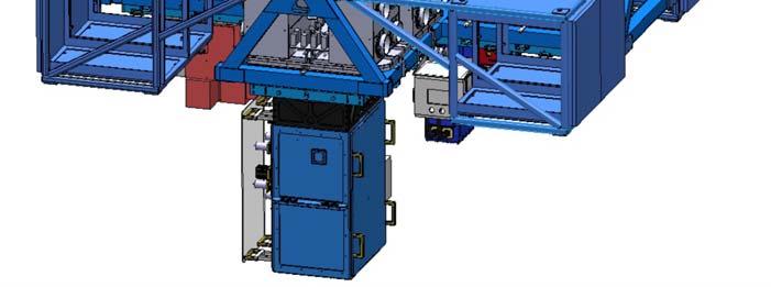


16 MULTIPLE INSTRUMENT MOUNT (MIM)


17 MULTIPLE INSTRUMENT MOUNT (MIM)
18 MULTIPLE INSTRUMENT MOUNT (MIM) UPGRADE In preparation to adding a new instrument (ISHELL) to the facility, we needed to insure that the current structure could support it. Quartus Engineering was selected with a RFP to perform a structural analysis of the MIM: Goal: verify that the addition of ishell can be supported by the existing system. if calculated strengths are below safety margins, identify components to be re enforced or re designed. Method: static, seismic and fatigue FEA analysis
 Components that are modeled as concentrated masses attached via rigid elements include: West, South, and East Rail")
19 MIM STRUCTURAL ANALYSIS Components that are explicitly modeled include: Mirror Cell Plates (8X) Interface Boxes w/ Shims (4X) MIM Quadmount Weldment North Rail Assembly Mirror Cell Plate Cabinet and Electronics MIM Weldment Cooler I/F Box North Truck Cabinet Support Weldments (4X) Components that are modeled as concentrated masses attached via rigid elements include: West, South, and East Rail Assemblies and Trucks Coolracks Cabinets & Electronics (4X) Cabinet Support Weldment Coolracks Coolers (2X) Instruments (4X) North Truck Instrument ishell Instrument North Rail Assembly 19
20 MIM SEISMIC ANALYSIS: OVERVIEW Structure analyzed in 3 different orientations: Zenith: DEC = 19 N; RA = 0 Horizon East: DEC = 19 N; RA = 60 E Horizon Southeast: DEC = 31 S; RA = 60 E Seismic loads of 0.95G Horizontal and 1.14G Vertical are applied to the structure in each orientation: Load levels and directions calculated using ASME code 9 load cases total analyzed: 3 telescope orientations X 3 earthquake horizontal directions Von Mises Stresses are recovered from shell elements Forces are recovered from weld lines, fasteners, and truck wheels Weld material strengths receive a knockdown factor of 0.6 Safety factors used for margin of safety calculations are defined in AISC: Safety factor of = 1.67 used for: Material Von Mises yield Safety factor of = 2.0 used for: Material Von Mises ultimate & bearing stress Weld tensile & shear stress Fastener stress (tensile yield, tensile ultimate, shear ultimate) Fastener gapping and slipping Truck wheel axial & radial loads 20

21 MIM SEISMIC ANALYSIS Material Stress Summary Conclusion: Mirror Cell Plates, Interface Boxes and Rail Support need to be reenforced Rail was later verified as being hardened, so margin are actually positive. No change needed. Fasteners size to be increased at the Interface Box / Shim junction.
 Occurs on upper interface to mirror cell around the top bolt Bolted joint takes 6150 lb of shear load Negative margins show in all 3 telescope orientations Always located")
 Occurs on upper interface to mirror cell at junction of 3 welded plates Major load path for center bolt to MIM as well as outer bolt to shim Three negative margin locations")
22 MIM SEISMIC ANALYSIS Material Stress Details (Negative Margins) MIRROR CELL PLATE: Min. Margin of Safety: 0.26 yield; 0.01 ultimate Max. Stress = 29.2 ksi (Horizon East) Occurs on upper interface to mirror cell around the top bolt Bolted joint takes 6150 lb of shear load Negative margins show in all 3 telescope orientations Always located around 3 rd bolt on mirror cells INTERFACE BOXES: Min. Margin of Safety: 0.43 yield; 0.23 ultimate Max. Stress = 37.7 ksi (Horizon East) Occurs on upper interface to mirror cell at junction of 3 welded plates Major load path for center bolt to MIM as well as outer bolt to shim Three negative margin locations exist in I/F boxes: Welded plates 3 way junction (37.7 ksi) Bolted joints to mirror cell (27 ksi) Bolted joints to shim (37 ksi)


23 MIM SEISMIC ANALYSIS Material Stress Details (Negative Margins) RAIL SUPPORT ASSEMBLY: Min. Margin of Safety: 0.48 yield; 0.30 ultimate Max. Stress = 41.3 ksi (Horizon East) Occurs on rail mount aligned near center of truck Peak stress is driven by bending in rail mount flange Negative margins show in all 3 telescope orientations Positive stress margins in all other rail support assembly material FASTENERS (Interface Box to Shim) Negative gapping and stress margins exist in bolts from interface boxes to shims Gapping margin = 0.41 Shear ultimate stress margin = 0.08 Tensile yield stress margin = 0.26 Tensile ultimate stress margin = 0.15 These smaller bolts react a large portion of the moment induced by the MIM Wide rectangular pattern forces them to take more load than the central 3/4 10 bolt to the MIM Bolt size = 3/8-16 Max axial force = 7821 lb Max shear force = 4012 lb
24 Structure analyzed in two telescope orientations MIM FATIGUE ANALYSIS: OVERVIEW Horizon Southeast: DEC = 31 S; RA = 60 E Horizon Northwest: DEC = 59 N; RA = 60 W Fatigue load of 1G applied in the gravity direction Fatigue analysis performed for 90,000 cycles (10 cycles/night, 300 nights/year, 30 year lifespan) For steel components (including welds), AISC gives a variety of fatigue strengths based on the location of the material (bolted joint, welded joint, etc) Stress ranges are determined for the maximum to minimum stresses that the structure sees as it moves from Horizon Southeast to Horizon Northwest orientation Forces are recovered from weld lines and truck wheels No safety factors are used for fatigue analysis as specified in AISC Bolted joints will not fatigue as long as joint does not gap

25 MIM FATIGUE ANALYSIS Material Stress Summary Same conclusion as for the Seismic Analysis. Upgrades needed for the same components. 25


26 MIM RE-ENFORCEMENT Increased Plates thickness Increased weld filets width Increased fasteners size Added 4 side braces All fasteners minimum Grade 8 26
27 MIM RE-ENFORCEMENT WORK SCHEDULE Re-design + Drawings Fabrication Preparation: Cable labeling, remove unscheduled instruments, Telescope Shutdown: OCT 19 th 29 th 2015 Preparation work: (4 days) - Remove Electronic cabinets, chillers, instrument - Lower MIM onto platform - Prep welding area - Protect Primary mirror Welding work: (4 days) - Cut-out old interface plates (x4) - Weld new interface plates (x4) Telescope Re-assembly: (3 days) Other parallel tasks: - Chillers Fans upgrade (6 days max) - SpeX work (8 days max) Note: Contingency built-in within different Tasks Oct 30 th = engineering = add l day of contingency 27

28 TELESCOPE BALANCING SYSTEM Movable Counterweights 28


29 TELESCOPE BALANCING SYSTEM Movable Counterweight locations 29


30 TELESCOPE BALANCING SYSTEM Fixed Counterweights 30
31 TELESCOPE BALANCING MODEL AND OPTIMIZATION TOOL Goal: - verify that the existing system can still be balanced after the addition of ISHELL - optimize the location and amount of the static counterweights - predict optimal location of the movable counterweights Method: - calculate sum of moments on the RA and DEC axis. Run theoretical balancing routine to find the smallest possible moments by moving the movable counterweights. 31
32 TELESCOPE BALANCING MODEL AND OPTIMIZATION TOOL 1) Model Inputs: Fixed values: - Masses: calculated/estimated from CAD model or measured - Center of Gravity: calculated/estimated from CAD model Parameters: - Instruments CoG: stowed and operation - Movable Counterweight: range and orientation vector Existing balanced configurations: - to determine / estimate unknown weights - Allocate Dummy Weights to compensate for approximations 2) Model Outputs: DEC and RA Moments (are they small enough to allow for stable telescope tracking?) Movable counterweights positions (and corresponding voltages) 32
33 TELESCOPE BALANCING MODEL AND OPTIMIZATION TOOL 3) Model Calculations: Moments are calculated for each component Assume movable CWs are centered DEC axis moments Zenith pointing M = W*y 90 South pointing M = W*z M = moment [in*lb] W = weight [lb] [x,y,z] = [x,y,z]-direction coordinate of CoG [in] RA axis moments Zenith pointing M = W*x 19 South, 90 East pointing (DEC and RA axes are perpendicular to each other) For components on CS: M = W*(z+7.992) For components on YK: M = W*( y*sin(19 )+z*cos(19 )+7.992) Sum moments for each axis in both orientations (4 moment sums total) DEC axis only sums components on CS RA axis sums components on CS and YK Use movable counterweights to try and zero moment balances 33
34 TELESCOPE BALANCING MODEL 4) Balancing steps: AND OPTIMIZATION TOOL Step 1: DEC 90 South Pointing (Tube Top/Bottom Balance) Calculate optimal position for the following Movable Counterweight Tube Vertical SW Tube Vertical NW Tube Vertical SE Tube Vertical NE Step 2: DEC Zenith Pointing (North/South Balance) Calculate optimal position for the following Movable Counterweight Tube Horizontal Bottom Tube Horizontal Top Step 3: RA 19 South, 90 East Pointing (Yoke Top/Bottom Balance) Calculate optimal position for the following Movable Counterweight Yoke Vertical W Yoke Vertical E Step 4: RA Zenith Pointing (East/West Balance) Calculate optimal position for the following Movable Counterweight Yoke Horizontal Center Yoke Horizontal S Bottom Yoke Horizontal S Top 34

35 TELESCOPE BALANCING MODEL AND OPTIMIZATION TOOL 35
36 TELESCOPE BALANCING METHOD Model is missing too much data (weight, CoG) or estimates are too far off to determinate the dummy weight accurately. Optimization of the static CW locations can still be done by hand For each instrument configuration, the movable CWs which are maxed out indicate where the unbalance resides. (Yoke or Tube Top/Bottom, North/South, East/West) Then, static CWs are added/removed to compensate. The telescope balancing procedure is run again to find new movable CWs locations Repeat until none of the configurations have maxed out movable CWs. Model equations can be used to predict the amount of static CWs to be added/removed. 36
Chapter 11. Keys, Couplings and Seals. Keys. Parallel Keys
 Chapter 11 Keys, Couplings and Seals Material taken for Keys A key is a machinery component that provides a torque transmitting link between two power-transmitting elements. The most common types of keys
Sheet 1 Variable loading
 Sheet 1 Variable loading 1. Estimate S e for the following materials: a. AISI 1020 CD steel. b. AISI 1080 HR steel. c. 2024 T3 aluminum. d. AISI 4340 steel heat-treated to a tensile strength of 1700 MPa.
Doc #: 2100-AD Revision: A. 4M Mayall Maintenance Manual. Author(s): Larry Reddell
: Larry Reddell") Doc #: 2100-AD-015-0003 Revision: A 4M Mayall Maintenance Manual Author(s): Larry Reddell 2100-AD-015-0003.DOCX 2 Revision Description Date Name --- Original: 2100-AD-015-0001 4/12/2014 Larry Reddell 2100-AD-015-0003.DOCX
Doc #: 2100-AD-015-0003 Revision: A 4M Mayall Maintenance Manual Author(s): Larry Reddell 2100-AD-015-0003.DOCX 2 Revision Description Date Name --- Original: 2100-AD-015-0001 4/12/2014 Larry Reddell 2100-AD-015-0003.DOCX
The g-2 Project at FNAL. Horst Friedsam John Kyle IWAA 2014 at Beijing October 2014
 Horst Friedsam John Kyle IWAA 2014 at Beijing 13-17 October 2014 Outline History and project purpose P5 and the Muon Campus development The meaning of the gyromagnetic ratio g Alignment requirements Status
Shaft Design. Dr. Mostafa Rostom A. Atia Associate Prof.
 Shaft Design Dr. Mostafa Rostom A. Atia Associate Prof. 1 Loading modes A shaft is a rotating member, usually of circular cross section, used to transmit power or motion. It provides the axis of rotation,
Support and Infrastructure
 Support and Infrastructure SoLID Director s Review Whit Seay February 23, 2014 SoLID Experimental Set-ups Design a system for mounting experimental apparatus that can be utilized by both set-ups. Integrate
2100-AD DRAFT Revision: -
 2100-AD-015-0008 DRAFT Revision: - 4 Meter TCS Encoder Alignment Procedure December 9, 2014 Patrick Dunlop Larry Reddell Victor Moreno Revision Description Date Name - Original: 2100-AD-015-0008 12/9/2014
CAPT JT Elder Commanding Officer NSWC Crane
 KeyMod vs. M-LOK Modular Rail System Comparison Abstract #19427 Presented By: Caleb McGee Date: 4 May 2017 CAPT JT Elder Commanding Officer NSWC Crane Dr. Brett Seidle, SES Technical Director NSWC Crane
Chapter 7. Shafts and Shaft Components
 Chapter 7 Shafts and Shaft Components 2 Chapter Outline Introduction Shaft Materials Shaft Layout Shaft Design for Stress Deflection Considerations Critical Speeds for Shafts Miscellaneous Shaft Components
TCS Axis Motor Tachometer. Replacement
 UNIVERSITY OF HAWAII INSTITUTE FOR ASTRONOMY 2680 Woodlawn Dr. Honolulu, HI 96822 NASA Infrared Telescope Facility TCS Axis Motor Tachometer.......... Replacement Eric Warmbier July 9, 2008 Version - Table
NONMANDATORY APPENDIX Q ARTICLE Q-1000 DESIGN RULES FOR CLAMP CONNECTIONS
 Page 1 of 7 NONMANDATORY APPENDIX Q ARTICLE Q-1000 DESIGN RULES FOR CLAMP CONNECTIONS Q-1100 INTRODUCTION Q-1110 SCOPE (a) The rules in Nonmandatory Appendix Q apply specifically to the design of clamp
Introduction. Lubrication Related Failures. Gear Couplings. Failure Analysis All Types (Page 1 of 7)
") All Types (Page 1 of 7) Introduction A gear coupling serves as a mechanical device which connects shafts of two separate machines and accommodates small amounts of shaft misalignment. Commercial gear couplings
All Types (Page 1 of 7) Introduction A gear coupling serves as a mechanical device which connects shafts of two separate machines and accommodates small amounts of shaft misalignment. Commercial gear couplings
Bearings. Rolling-contact Bearings
 Bearings A bearing is a mechanical element that limits relative motion to only the desired motion and at the same time it reduces the frictional resistance to the desired motion. Depending on the design
PIPINGSOLUTIONS, INC.
 Piping Stress Analysis Where do I start? The following information will take you step-by-step through the logic of the data collection effort that should occur prior to beginning to model a piping system
GLAST Large Area Telescope:
 GLAST Large Area Telescope: Gamma-ray Large Area Space Telescope MGSE Integration Readiness Status Two Tower Operations Eric Gawehn SU-SLAC LAT I&T MGSE Dept. Manager egawehn@slac.stanford.edu 650 926
Chrysler A-Body Tubular A-Arms Installation Instructions A-ARM INSTALLATION
 1967-1976 Dodge Demon 1112 67-72 Chrysler A-Body Tubular A-Arms Installation Instructions Thank you for your purchase of this Hotchkis Performance product. Your A-Arm set was designed with the performance
114 NOSE SEIKO CO.,LTD NOSE SEIKO CO.,LTD
 114 NOSE SEIKO CO.,LTD NOSE SEIKO CO.,LTD 115 and Part Code Applicable axis diameter Feature Part Code 5 ~ 3 General purpose cam follower with screwdriver groove on the stud head. Available with stainless
Shifting gears: simplify your design with slewing ring bearings
 White Paper Shifting gears: simplify your design with slewing ring bearings Scott Hansen, VP, Manufacturing Planning, Kaydon Bearings, an SKF Group company A slewing ring bearing has rolling elements designed
MOLLER Hybrid Toroid Engineering Design
 MOLLER Hybrid Toroid Engineering Design Presented by Ernie Ihloff, MIT-Bates With Contributions From: Jim Kelsey, MIT-Bates Jason Bessuille, MIT-Bates Presented to MOLLER Collaboration Thursday, 8 th May,
International Journal of Scientific & Engineering Research, Volume 4, Issue 7, July ISSN BY B.MADHAN KUMAR
 International Journal of Scientific & Engineering Research, Volume 4, Issue 7, July-2013 485 FLYING HOVER BIKE, A SMALL AERIAL VEHICLE FOR COMMERCIAL OR. SURVEYING PURPOSES BY B.MADHAN KUMAR Department
Modular. Precise. Robust. AGE-S-XYZ Compensation Unit
 Modular. Precise. Robust. AGE-S-XYZ Compensation Unit Compensation unit compensating in XY- and Z-direction. Field of Application Palletizing, joining, and assembly of workpieces Advantages Your benefit
Accessories smart additions for efficiency and intelligent performance
 smart additions for efficiency and intelligent performance Metal bellows couplings Perfectionists you can count on Metal bellows couplings are designed for the highest requirements in servo drive technology.
AP Physics B: Ch 20 Magnetism and Ch 21 EM Induction
 Name: Period: Date: AP Physics B: Ch 20 Magnetism and Ch 21 EM Induction MULTIPLE CHOICE. Choose the one alternative that best completes the statement or answers the question. 1) If the north poles of
ZERO BACKLASH GEARING
 ZERO BACKLASH GEARING Based on Nexen s innovative Roller Pinion technology, the Geared Bearing comes complete with a gear and a precision grade, high capacity bearing. With a wide range of sizes and ratios,
PC-Series Precision Linear Actuators. Optimize Your Machine and Save Energy With Reliable, High Performance, Compact Actuators
 PC-Series Precision Linear Actuators Optimize Your Machine and Save Energy With Reliable, High Performance, Compact Actuators Make the Change to Electric Enjoy superior performance and save time and energy
Design, Modelling & Analysis of Double Wishbone Suspension System
 Design, Modelling & Analysis of Double Wishbone Suspension System 1 Nikita Gawai, 2 Deepak Yadav, 3 Shweta Chavan, 4 Apoorva Lele, 5 Shreyash Dalvi Thakur College of Engineering & Technology, Kandivali
Application Information
 Moog Components Group manufactures a comprehensive line of brush-type and brushless motors, as well as brushless controllers. The purpose of this document is to provide a guide for the selection and application
Plastic Hinging Considerations for Single-Column Piers Supporting Highly Curved Ramp Bridges
 Plastic Hinging Considerations for Single-Column Piers Supporting Highly Curved Ramp Bridges Western Bridge Engineers Seminar Reno, NV Greg Griffin, P.E., S.E. - Senior Bridge Engineer e Griffin, P.E.,
DESIGN OF MACHINE MEMBERS - I
 R10 Set No: 1 III B.Tech. I Semester Regular and Supplementary Examinations, December - 2013 DESIGN OF MACHINE MEMBERS - I (Mechanical Engineering) Time: 3 Hours Max Marks: 75 Answer any FIVE Questions
Comparison Chart. extremely difficult. Finally, separated components can rarely be re-used.
 JAN 2014 Traditional Connections Why Go Keyless Keyed Bushing Systems Both QD and Taper-Lock bushing and weld-on hub systems are popular component mounting technologies. Yet both are ultimately keyed connections
DEPARTMENT OF MECHANICAL ENGINEERING
 DEPARTMENT OF MECHANICAL ENGINEERING UABMCC01-DESIGN OF MACHINE ELEMENTS QUESTION BANK Prepared By: Dr.S.Prabhakaran, Associate Professor/Mechanical Engg. Unit -1 STEADY STRESSES AND VARIABLE STRESSES
Maximum Performance Contoured Diaphragm Couplings
 Maximum Performance Contoured Diaphragm Couplings Goodrich Couplings offers: Best Balance Repeatability Lowest Weight Highest Reliability Ease of Installation Stainless Steel Diaphragms Goodrich Corporation
EURO-BEARINGS LTD COMBINED ROLLER BEARINGS & MATING STEEL PROFILES CATALOGUE. Tel: +44 (0)
") COMBINED ROLLER BEARINGS & MATING STEEL PROFILES CATALOGUE email: sales@euro-bearings.com Tel: +44 (0)1908 511733 2015 CATALOGUE CONTENTS COMBINED ROLLER BEARINGS Standard CR Bearings Eccentric Adjustable
COMBINED ROLLER BEARINGS & MATING STEEL PROFILES CATALOGUE email: sales@euro-bearings.com Tel: +44 (0)1908 511733 2015 CATALOGUE CONTENTS COMBINED ROLLER BEARINGS Standard CR Bearings Eccentric Adjustable
A Recommended Approach to Pipe Stress Analysis to Avoid Compressor Piping Integrity Risk
 A Recommended Approach to Pipe Stress Analysis to Avoid Compressor Piping Integrity Risk by: Kelly Eberle, P.Eng. Beta Machinery Analysis Calgary, AB Canada keberle@betamachinery.com keywords: reciprocating
MAIN SHAFT SUPPORT FOR WIND TURBINE WITH A FIXED AND FLOATING BEARING CONFIGURATION
 Technical Paper MAIN SHAFT SUPPORT FOR WIND TURBINE WITH A FIXED AND FLOATING BEARING CONFIGURATION Tapered Double Inner Row Bearing Vs. Spherical Roller Bearing On The Fixed Position Laurentiu Ionescu,
Revision and Errata List AISC Steel Construction Manual, 13 th Edition, Third Printing (Revision 2 June 2010)
") Revision and Errata List AISC Steel Construction Manual, 13 th Edition, Third Printing (Revision 2 June 2010) The following list represents corrections that have been made in the Fourth Printing of the
Revision and Errata List AISC Steel Construction Manual, 13 th Edition, Third Printing (Revision 2 June 2010) The following list represents corrections that have been made in the Fourth Printing of the
CONTENT. 1. Syllabus 2. Introduction 3. Shaft 4. Coupling. Rigid coupling. Flange coupling. Sleeve (or) muff coupling Split muff coupling
 muff coupling Split muff coupling") UNIT II 1. Syllabus 2. Introduction 3. Shaft 4. Coupling Rigid coupling CONTENT Flange coupling Protected flange coupling Unprotected flange coupling Marine type flange coupling Sleeve (or) muff coupling
UNIT II 1. Syllabus 2. Introduction 3. Shaft 4. Coupling Rigid coupling CONTENT Flange coupling Protected flange coupling Unprotected flange coupling Marine type flange coupling Sleeve (or) muff coupling
CHAPTER 5 PREVENTION OF TOOTH DAMAGE IN HELICAL GEAR BY PROFILE MODIFICATION
 90 CHAPTER 5 PREVENTION OF TOOTH DAMAGE IN HELICAL GEAR BY PROFILE MODIFICATION 5.1 INTRODUCTION In any gear drive the absolute and the relative transmission error variations normally increases with an
Riverhawk Company 215 Clinton Road New Hartford NY (315) Free-Flex Flexural Pivot Engineering Data
 Free-Flex Flexural Pivot Engineering Data") Riverhawk Company 215 Clinton Road New Hartford NY (315)768-4937 Free-Flex Flexural Pivot Engineering Data PREFACE Patented Flexural Pivot A unique bearing concept for applications with limited angular
Riverhawk Company 215 Clinton Road New Hartford NY (315)768-4937 Free-Flex Flexural Pivot Engineering Data PREFACE Patented Flexural Pivot A unique bearing concept for applications with limited angular
Series 249 and 249N Swivels
 Series 249 and 249N Swivels l Features Strong, durable, versatile swivels specifically designed for the rigorous demands of closed-loop servohydraulic testing applications Series 249 swivels are available
INSTALLATION INSTRUCTIONS FOR: RE7500 SERIES TJ EXTREME DUTY LONG ARM TRI-LINK SYSTEM INCLUDING TJ UNLIMITED
 RUBICON EXPRESS 3290 MONIER CIR., RANCHO CORDOVA, CA. 95742 916-473-4600 INSTALLATION INSTRUCTIONS FOR: RE7500 SERIES TJ EXTREME DUTY LONG ARM TRI-LINK SYSTEM INCLUDING TJ UNLIMITED Congratulations on
Synchronous Belt Failure Analysis Guide
 Synchronous Belt Failure Analysis Guide Contents Part 1: Common Causes of Belt Failure Normal Belt Wear and Failure Belt Crimp Failures Shock Load Part 2: Improper Belt Installation Tension Introduction
Engineering Analysis. Team: 5 Guys Engineering + 1 Nathan Bessette, Rahul Bhatia, Andrew Cass, Glen Stewart
 Engineering Analysis Presentation ME 4182 Team: 5 Guys Engineering + 1 Nathan Bessette, Rahul Bhatia, Andrew Cass, Zeeshan Saiyed, Glen Stewart YJ JChok Automatic Whiteboard Wiper Last Time Last Time Layout
PIONEER RESEARCH & DEVELOPMENT GROUP
 Design and Stress Analysis of Tow Bar for Medium Sized Portable Compressors Pankaj Khannade 1, Akash Chitnis 2, Gangadhar Jagdale 3 1,2 Mechanical Department, University of Pune/ Smt. Kashibai Navale College
Tim Johnson OPTI521 Report 1 1 of 5
 Tim Johnson OPTI 521-Optomechanical Engineering Report 1 Synopsis of Technical Report Chapter 8.3 Semikinematic Mounting for Small Mirrors Opto-Mechanical Systems Design by P. R. Yoder, 2006 11-14-07 Abstract
PROJ. NO SECTION HYDRONIC PUMPS
 SECTION 23 21 23 HYDRONIC PUMPS PART 1 - GENERAL 1.1 RELATED DOCUMENTS A. Drawings and general provisions of the Contract, including General and Supplementary Conditions and Division 01 Specification Sections,
EXAMPLES INTRODUCTION
 AMEM 316 (AUTO308): Machine Elements I EXAMPLES INTRODUCTION EXAMPLES INTRODUCTION Example 1 (Hamrock p.53) As shown in figure 2.12(a), a 3m long bar is supported at the left end (B) by a 6 ram diameter
PRODUCT LINE WHEELBASE & CAPACITIES
 PRODUCT LINE WHEELBASE & CAPACITIES TX-4030 (30,000-lb. Cap. at 36" L.C., 132" WB) Rigger Application: 40,000-lbs. Cap. at 36 L.C. if traveling less than 1 mph up to 48-in. lift. Truck is shown with available
Now you can get design flexibility and lasting performance from our complete family of AccuDrive Precision Products.
 ACCUDRIVE PRECISION PRODUCTS Now you can get design flexibility and lasting performance from our complete family of AccuDrive Precision Products. Series W Precision Servo Gearhead Output torque up to 8,500
Senior Design Project P07110 METEOR Vertical Test Stand Rochester Institute of Technology, Rochester, New York
 Senior Design Project P07110 METEOR Vertical Test Stand Rochester Institute of Technology, Rochester, New York Michael Saitta (Team Leader)- Mechanical Engineering Brian Frost- Mechanical Engineering Amberly
QuickStick Repeatability Analysis
 QuickStick Repeatability Analysis Purpose This application note presents the variables that can affect the repeatability of positioning using a QuickStick system. Introduction Repeatability and accuracy
Locking Assemblies Shrink Discs Rigid Couplings.
 M I N I Locking Assemblies Shrink Discs Rigid Couplings www.mav.it our company We are an Italian company world renowned for our creativity and ethics. Established in 1989 we have rapidly built a reputation
Skid against Curb simulation using Abaqus/Explicit
 Visit the SIMULIA Resource Center for more customer examples. Skid against Curb simulation using Abaqus/Explicit Dipl.-Ing. A. Lepold (FORD), Dipl.-Ing. T. Kroschwald (TECOSIM) Abstract: Skid a full vehicle
Product overview. Joints. Circlips for ball seats DIN K0714. Quick plug couplings with radial offset compensation K0709. Page 837.
 Joints 825 Product overview Joints Quick plug couplings with radial offset compensation K0709 Quick plug couplings with radial offset compensation and screw-on flange K0710 Quick plug couplings with angular
Assemblies for Parallel Kinematics. Frank Dürschmied. INA reprint from Werkstatt und Betrieb Vol. No. 5, May 1999 Carl Hanser Verlag, München
 Assemblies for Parallel Kinematics Frank Dürschmied INA reprint from Werkstatt und Betrieb Vol. No. 5, May 1999 Carl Hanser Verlag, München Assemblies for Parallel Kinematics Frank Dürschmied Joints and
Preliminary Detailed Design Review
 Preliminary Detailed Design Review Project Review Project Status Timekeeping and Setback Management Manufacturing techniques Drawing formats Design Features Phase Objectives Task Assignment Justification
In-house development Own manufacturing Sole distributor in Germany Working with distributors worldwide
 In-house development Own manufacturing Sole distributor in Germany Working with distributors worldwide External Clamping devices Overview 3073 Mini-Range For very low torque transmission Very small profile
PowerLink JC Series Torque Transducer User Manual
 PowerLink JC Series Torque Transducer User Manual XiangYi (Hong Kong) Power Testing Instrument Co. Ltd. 0 JC Series Torque Transducer User Manual How to install the sensor properly JC-type torque transmission
Transmission Overhaul Procedures-Bench Service
 How to Assemble the Lower Reverse Idler Gear Assembly Special Instructions In 1996 Eaton changed the reverse idler system design. In the nut design, the reverse idler bearing was lubricated through a hole
QualityWatch. Report Number 1 CAPA. November A Periodic Report on Non CAPA Certified Aftermarket Replacement Parts
 CAPA QualityWatch A Periodic Report on Non CAPA Certified Aftermarket Replacement Parts Report Number 1 November 2011 1 Certified Automotive Parts Association 1000 Vermont Avenue NW Suite 1010 Washington,
CHAPTER 3 DESIGN OF THE LIMITED ANGLE BRUSHLESS TORQUE MOTOR
 33 CHAPTER 3 DESIGN OF THE LIMITED ANGLE BRUSHLESS TORQUE MOTOR 3.1 INTRODUCTION This chapter presents the design of frameless Limited Angle Brushless Torque motor. The armature is wound with toroidal
PF Coil Fabrication Overview
 PF Coil Fabrication Overview PF Coils Information Meeting Barcelona - 15 th October 2012 This presentation is intended for reference purposes only and is not a legally binding document PF Building Layout
Performance Based Design for Bridge Piers Impacted by Heavy Trucks
 Performance Based Design for Bridge Piers Impacted by Heavy Trucks Anil K. Agrawal, Ph.D., P.E., Ran Cao and Xiaochen Xu The City College of New York, New York, NY Sherif El-Tawil, Ph.D. University of
South Bend Duramax DD
 South Bend Duramax DD Installation Instructions Torque specifications: Flywheel to crank 140-150 ft. lbs. Pressure plate to flywheel is 45 ft. lbs. Unbolt pressure plate from flywheel in a star pattern
Single and Bi-Parting Manual Sliding Doors. Installation. R-PLUS Cold Storage Doors
 Single and Bi-Parting Manual Sliding Doors Installation Door Leaf J-Box Door Heater J-Box Door Header Adjusting Rod Door Hanger Assembly Track Roller Door Track SJO Cable Trailing Edge Door Snubber Neoprene
Theory of Machines II EngM323 Laboratory User's manual Version I
 Theory of Machines II EngM323 Laboratory User's manual Version I Table of Contents Experiment /Test No.(1)... 2 Experiment /Test No.(2)... 6 Experiment /Test No.(3)... 12 EngM323 Theory of Machines II
FREE STANDING WORK STATION JIB CRANE
 SECTION 14661 FREE STANDING WORK STATION JIB CRANE ***** Gorbel, Inc. manufacturers a broad range of material handling cranes including monorail, bridge, gantry, and jib cranes. Numerous work station and
MAGNETIC EFFECTS OF ELECTRIC CURRENT
 MAGNETIC EFFECTS OF ELECTRIC CURRENT It is observed that when a compass is brought near a current carrying conductor the needle of compass gets deflected because of flow of electricity. This shows that
SURFACE VEHICLE RECOMMENDED PRACTICE
 SURFACE VEHICLE RECOMMENDED PRACTICE J1095 Issued 1982-06 Revised 2003-03 REV. MAR2003 Superseding J1095 MAR1995 Spoke Wheels and Hub Fatigue Test Procedures 1. Scope This SAE Recommended Practice provides
RL1900 SERIES. Mounting Assembly Kit. Installation Guide
 RL1900 SERIES Mounting Assembly Kit Installation Guide 9 SM 25711 Contents 1. Introduction... 1 2. Mechanical Installation... 2 2.1 General Installation Guidelines for Tank Mounts... 2 2.2 Installing the
Refer to separate Installation Instructions for installation details.
 OWNER S GUIDE 8A000729 DuraLift 13.5 13,500 CAPACITY Link Mfg. Ltd. 223 15th St. N.E. Sioux Center, IA USA 51250-2120 www.linkmfg.com QUESTIONS? CALL CUSTOMER SERVICE 1-800-222-6283 DEALER / INSTALLER:
Fatigue Life Estimation of Chassis Frame FESM Bracket for Commercial Vehicle
 Fatigue Life Estimation of Chassis Frame FESM Bracket for Commercial Vehicle Shivakumar M.M 1, Nirmala L 2 ¹M-Tech Student, Dept. of Mechanical Engineering,K.S Institute of Technology, Bangalore, India
Design of Helical Gear and Analysis on Gear Tooth
 Design of Helical Gear and Analysis on Gear Tooth Indrale Ratnadeep Ramesh Rao M.Tech Student ABSTRACT Gears are mainly used to transmit the power in mechanical power transmission systems. These gears
TXB-250M. The master parts depot ships genuine TAYLOR parts nationwide and is a key component in the Sudden Service, Inc. dealer network.
 PRODUCT LINE WHEELBASE & CAPACITIES TXB-180S (18,000-lb. Cap. at 24" L.C., 110" WB) TXB-200S (20,000-lb. Cap. at 24" L.C., 110" WB) TXB-250M (25,000-lb. Cap. at 24" L.C., 121" WB) TXB-300L (30,000-lb.
ALFRA PRESS - overview
 70 ALFRA PRESS 71 ALFRA PRESS - overview ALFRA PRESS AP 250 ALFRA PRESS AP 400 Page 74 Page 78 Control cabinet housing, Control cabinet doors, Mounting panels Control cabinet housing, Control cabinet doors,
MM FIXED ADJUSTABLE PLATE FIXED ADJUSTABLE RADIAL AXIAL A B C D E
 Hevi-Rail Roller Bearings and Linear Guideways SYSTEM MAX. STATIC COMBINED HEVI-RAIL BEARING WITH WELDED LOAD* GENERAL DIMENSIONS** BEARING FLANGE PLATE kn MM FLANGE FIXED ADJUSTABLE PLATE FIXED ADJUSTABLE
Components for parallel kinematics
 Components for parallel kinematics Series GLK, GLAE Joints and struts form the core components of machines with parallel kinematics (PKM). Irrespective of the control technology possibilities, good mechanical
EXPERIMENT 13 QUALITATIVE STUDY OF INDUCED EMF
 220 13-1 I. THEORY EXPERIMENT 13 QUALITATIVE STUDY OF INDUCED EMF Along the extended central axis of a bar magnet, the magnetic field vector B r, on the side nearer the North pole, points away from this
Load Cell for Manually Operated Presses Model 8451
 w Technical Product Information Load Cell for Manually Operated Presses 1. Introduction... 2 2. Preparing for use... 2 2.1 Unpacking... 2 2.2 Using the instrument for the first time... 2 2.3 Grounding
Reduction of Self Induced Vibration in Rotary Stirling Cycle Coolers
 Reduction of Self Induced Vibration in Rotary Stirling Cycle Coolers U. Bin-Nun FLIR Systems Inc. Boston, MA 01862 ABSTRACT Cryocooler self induced vibration is a major consideration in the design of IR
Graph-X-Cutter. Reliable turnkey solutions for any application requiring value, performance, and versatility. multicam.com
 Graph-X-Cutter Reliable turnkey solutions for any application requiring value, performance, and versatility. multicam.com 1 AFFORDABLE, HIGH-SPEED DIGITAL FINISHING SYSTEM GRAPH-X-CUTTER The MultiCam Graph-X-Cutter
GPK for Design and Rating of Industrial Gearboxes
 GPK for Design and Rating of Industrial Gearboxes KISSsys models: Bevel-Helical gear package includes KISSsys models for single bevel gearbox (right angle gearbox) and bevel gearboxes including one to
Components for parallel kinematics
 Components for parallel kinematics Series GLK, GLK 2, GLK 3 and GLAE Parallel kinematic components consist of a number of parallel, longitudinally adjustable mechanical struts that are arranged between
LEAD SCREWS 101 A BASIC GUIDE TO IMPLEMENTING A LEAD SCREW ASSEMBLY FOR ANY DESIGN
 LEAD SCREWS 101 A BASIC GUIDE TO IMPLEMENTING A LEAD SCREW ASSEMBLY FOR ANY DESIGN Released by: Keith Knight Kerk Products Division Haydon Kerk Motion Solutions Lead Screws 101: A Basic Guide to Implementing
Commercial Hopper Tanks (CHT)
") Commercial Hopper Tanks (CHT) Total Value. Total Systems. NCHT & FCHT Series The right tank for the right job. Commercial hopper tanks are typically used in applications where routine clean out is required,
Commercial Hopper Tanks (CHT) Total Value. Total Systems. NCHT & FCHT Series The right tank for the right job. Commercial hopper tanks are typically used in applications where routine clean out is required,
TXB-250M PRODUCT LINE WHEELBASE & CAPACITIES. (30,000-lb. Cap. at 24" L.C., 140" WB)
") PRODUCT LINE WHEELBASE & CAPACITIES TXB-180S TXB-200S TXB-250M TXB-300L (18,000-lb. Cap. at 24" L.C., 110" WB) (20,000-lb. Cap. at 24" L.C., 110" WB) (25,000-lb. Cap. at 24" L.C., 121" WB) (30,000-lb.
PRODUCT LINE WHEELBASE & CAPACITIES TXB-180S TXB-200S TXB-250M TXB-300L (18,000-lb. Cap. at 24" L.C., 110" WB) (20,000-lb. Cap. at 24" L.C., 110" WB) (25,000-lb. Cap. at 24" L.C., 121" WB) (30,000-lb.
CHAPTER 4 HARDWARE DEVELOPMENT OF DUAL ROTOR RADIAL FLUX PERMANENT MAGNET GENERATOR FOR STAND-ALONE WIND ENERGY SYSTEMS
 66 CHAPTER 4 HARDWARE DEVELOPMENT OF DUAL ROTOR RADIAL FLUX PERMANENT MAGNET GENERATOR FOR STAND-ALONE WIND ENERGY SYSTEMS 4.1 INTRODUCTION In this chapter, the prototype hardware development of proposed
EMC-HD. C 01_2 Subheadline_15pt/7.2mm
 C Electromechanical 01_1 Headline_36pt/14.4mm Cylinder EMC-HD C 01_2 Subheadline_15pt/7.2mm 2 Elektromechanischer Zylinder EMC-HD Short product name Example: EMC 085 HD 1 System = ElectroMechanical Cylinder
Bellows Page 415. Overview Universal Joints. Single Universal Joints. Speeds* max. min
 Overview Universal Joints Single Universal Joints Type UKM GF KE WEL RW AR WE WEN WER Material Plastic Plastic Stainless STAINLESS Bearings Bores mm 2-10 8-16 0-40 6-30 6-45, hardened 6-30, hardened 6-40
Design Aids For Structural Welded Wire Reinforcement (Metric Units for WWR/Rebar Comparison Tables)
") TF 209-R-08 Metric Design Aids For Structural Welded Wire Reinforcement (Metric Units for WWR/Rebar Comparison Tables) INTRODUCTION This Tech Fact* provides basic information on coldworked wire and welded
TF 209-R-08 Metric Design Aids For Structural Welded Wire Reinforcement (Metric Units for WWR/Rebar Comparison Tables) INTRODUCTION This Tech Fact* provides basic information on coldworked wire and welded
RED RAVEN, THE LINKED-BOGIE PROTOTYPE. Ara Mekhtarian, Joseph Horvath, C.T. Lin. Department of Mechanical Engineering,
 RED RAVEN, THE LINKED-BOGIE PROTOTYPE Ara Mekhtarian, Joseph Horvath, C.T. Lin Department of Mechanical Engineering, California State University, Northridge California, USA Abstract RedRAVEN is a pioneered
Start-up Experiences with Operation & Maintenance of Motor Operated Valves in a Delayed Coker
 Start-up Experiences with Operation & Maintenance of Motor Operated Valves in a Delayed Coker Presented during the Coking.com Safety Seminar Houston, Texas USA April 18-21, 2005 Michael Fynan Staff Mechanical
Pre-lab Questions: Please review chapters 19 and 20 of your textbook
 Introduction Magnetism and electricity are closely related. Moving charges make magnetic fields. Wires carrying electrical current in a part of space where there is a magnetic field experience a force.
ACCUDRIVE PRECISION PRODUCTS
 ACCUDRIVE SERIES S ACCUDRIVE PRECISION PRODUCTS Now you can get design flexibility and lasting performance from our complete family of AccuDrive Precision Products. Series W Precision Servo Gearhead Output
Hi-Z Antennas 4-8 PRO UP Level2 8 Element Circle Array Manual Converts the Hi-Z 4 to the Hi-Z 4-8PRO
 1 HIGH PERFORMANCE HF RECEIVING SYSTEMS & COMPONENTS Hi-Z Antennas 4-8 PRO UP Level2 8 Element Circle Array Manual Converts the Hi-Z 4 to the Hi-Z 4-8PRO Hi-Z 4-8PRO Shack Switch Hi-Z 4-8PRO PnP Interface
Commercial Hopper Tanks (CHT)
") Commercial Hopper Tanks (CHT) Total Value. Total Systems. NCHT & FCHT Series The right tank for the right job. Commercial hopper tanks are typically used in applications where routine clean out is required,
Commercial Hopper Tanks (CHT) Total Value. Total Systems. NCHT & FCHT Series The right tank for the right job. Commercial hopper tanks are typically used in applications where routine clean out is required,
PPED SERIES. Hydraulic press brakes LVDGROUP.COM ACCURATE, ECONOMICAL BENDING
 Hydraulic press brakes PPED SERIES ACCURATE, ECONOMICAL BENDING LVDGROUP.COM 2 # PPED SERIES PPED SERIES ACCURATE, ECONOMICAL BENDING Practical and easy to use, PPED press brakes are ideal for a wide range
 18. KSP 18. KSP 18.1 1200016 1200016 18.2 18.3 1200016 1200016 18.4 18.5 1200016 1200016 18.6 18.7 1200016 1200016 18.8 18.9 1200016 DARLEY BASIC ASSEMBLING TECHNIQUES Work with clean tools in clean surroundings
RZR 800 SLP Clutch Kit Installation Instructions
 RZR 800 SLP Clutch Kit Installation Instructions Clutch Removal A-1. Remove seats and seat retaining bar from RZR. (Rear seats and seat retaining bar in RZR-4) Illustration #1 A-2. Loosen hose clamp located
EZ Mount 1. Load Cell Mounting Kit. Installation Guide
 EZ Mount 1 Load Cell Mounting Kit Installation Guide 9 25710 Contents 1. Introduction... 1 2. Mechanical Installation... 2 2.1 General Installation Guidelines for Tank Mounts... 2 2.2 Installing the EZ