High Accessibility Cabinet Insert
|
|
|
- Elisabeth Andrea Freeman
- 5 years ago
- Views:
Transcription

1 Central Washington University All Undergraduate Projects Undergraduate Student Projects Summer 2017 High Accessibility Cabinet Insert Matthew Leal Central Washington University, Follow this and additional works at: Part of the Applied Mechanics Commons, Computer-Aided Engineering and Design Commons, and the Manufacturing Commons Recommended Citation Leal, Matthew, "High Accessibility Cabinet Insert" (2017). All Undergraduate Projects This Undergraduate Project is brought to you for free and open access by the Undergraduate Student Projects at It has been accepted for inclusion in All Undergraduate Projects by an authorized administrator of For more information, please contact

2 High Accessibility Cabinet Insert By Matthew Leal CWU Mechanical Engineering Technology
3 Table of Contents High Accessibility Cabinet Insert... 1 Matthew Leal... 1 Abstract... 6 Introduction... 6 Motivation:... 6 Function Statements... 6 Design Requirements... 7 Success Criteria... 7 Scope... 7 Benchmark... 7 Project Success... 8 Design and Analyses... 9 Approach: Proposed Solution... 9 Design Description... 9 Performance Predictions Description of Analyses Analyses Device: Parts, Shapes, and Conformation Device Assembly Methods and Construction Solution Method Construction Renderings Operation Post Manufacturing Discussion, issues, and successes Testing Method Scope of Testing TEST Test 1 Procedure TEST Test 2 Procedure Spring Rework Phase (Iteration 2) Budget/Schedule/Project Management Managerial Approach... 37
4 Cost and Budget Schedule Discussion Project Progression Successes Learning through design iteration, and the future of this project Conclusion Acknowledgments References Appendices Appendix A Description Assumptions Model Information Material Properties Loads and Fixtures Mesh information Mesh information - Details Study Results Conclusion Appendix B... 98
5 Appendix C: Appendix D: Appendix E: Appendix H Testing report and Data Appendix J:
6 Appendix X
7 Abstract Title and Author: High-Accessibility Cabinet Insert by Matthew Leal (Mechanical Engineering Technology) Abstract: Watching grandparents and parents get older, the struggle of day-to-day activities generally increases. One of the most recurring issues the older generation experiences nearly daily is their inability to reach dishes, glassware, and other things on the topmost shelves of a kitchen. Not only is it difficult for them to use things such as stepstools, it also becomes increasingly dangerous. With age, a fall from any height could be catastrophic. With this scenario in mind, a user-friendly cabinet insert would be a very effective way to combat this issue. However, many existing models of cabinet designed to fit these requirements operate using two linkage arms, and thus, have a higher material and manufacturing cost. One of the goals of this project is to reduce the overall cost and time to manufacture for a device that would be as effective as other benchmarked devices. This called for a design with only a single linkage arm. The device must also reduce the amount of force required to lift the nominal load by 50%. The insert, consisting of gas spring-assisted lowering shelf, will allow the user to pull items at a significant height down to a more reasonable level. The completed shelf does function as designed, however, the challenge of maintaining structural integrity with only one link arm was a large roadblock throughout this project. Keywords: Mechanical Design, Material Strengths, Engineering, Gas Spring, Manufacturing, Materials Motivation: Introduction Watching grandparents and parents get older, it is clear that the struggle of day-to-day activities generally increases. One of the most recurring issues the older generation go through at least once a day is their inability to reach dishes, glassware, and other things on the topmost shelves in her kitchen. Not only is it difficult for them to use things such as stepstools, it also becomes increasingly dangerous, as with age, a fall from any height could be catastrophic. With this scenario in mind, the need for an easily handled cabinet insert is extremely high. This insert will consist of two shelves that will unfold towards the user, and downward, significantly lowering the height at which the top shelf items are located. This project also has the potential to help those with disabilities, such as those in wheelchairs, and overall lesser locomotive capability. Function Statements This device must bring the contents of a high kitchen shelf to a lower level.
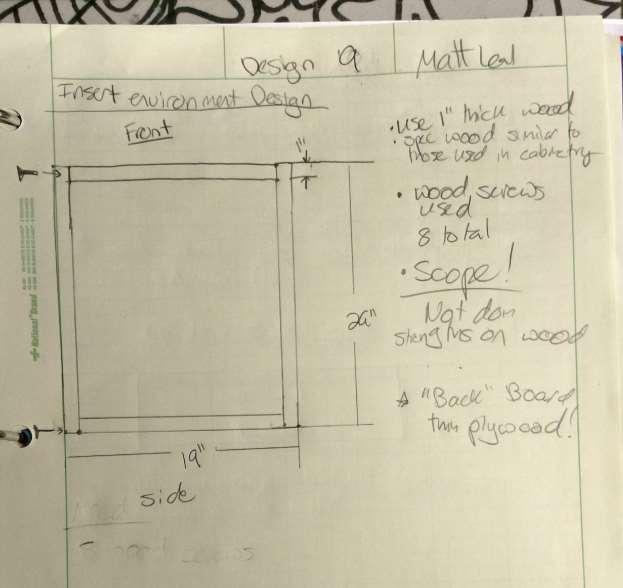
8 Design Requirements This device must be able to do the following: Must hold a nominal weight of 15#, and a max weight of 30# Must lower highest shelf between to bottom of cabinet space. Must fit into a standard 27 x 16 x 11 cabinet space Entire unit must weigh less than 30# without load Must have a safety factor at least 1.5 on strengths of linkage arms Must assist user needed force to raise nominal load by at least 50% Success Criteria In order to consider this project a success, the device must successfully fit into a standard 27 x 16 x 11 cabinet. It also must completely lower the highest shelf to a comfortable height, which in this case, is to a level below the lowest shelf on the cabinet. It also must be easy to operate, and assist the user in raising the nominal load by 50%. The forces necessary to move the assembly must comply with the forces predicted in the User Force Analysis (Appendix 9-11) up to within 10%. Scope For this project, the cabinet itself will be replicated with a wooden box built to the same specifications of the standard cabinet space in order to simulate the environment the insert would experience in the real world. Most of the parts, such as the physical shelf baskets themselves will be specc d and purchased according to manufacturer specs on weight limits. All fasteners will also be specc d and purchased according to manufacturer specs on strength limits, and also on what will be appropriate for the loads involved. Also excluded in the specs of this assignment are the practicality of the shelf holding dishes. There will only a guard rod keeping the dishes from falling out, when in reality, there would be more of an aesthetically pleasing way of keeping the dishes in during transportation. Benchmark There are a few similar concepts on the market today that accomplish the same task. Most of these are electrically powered, and some use hydraulics to transport the load at hand. However, one cabinet insert that is only user powered is for sale on kitchensource.com, and uses a similar linkage system to transport the load to the user. While there is not a lot of information on the way this product operates besides a short.gif on their website, I intended to mimic the descent pattern this device uses, as can be seen on this website.

9 Most of these are those that comply with the ADA for those with disabilities, so there will be quite a large variance between projects. The links below are a few benchmarks with similar design ideas to those that will be used in this project, along with an example in figure This benchmark does use a gas-assist technology, which seems to be referring to the gas spring seen in some of their photos. Figure 1: ADA Benchmark. Most of these benchmarks are electrically powered, which will be avoided for this project. However, overall design choices used for load bearing capabilities will be useful in the design choices for this project, along with the use of a gas spring. Project Success In order to quantify this project, a few crucial boxes must be checked off. One being the overall design function to lower the highest shelf to the same height of the lowest shelf. As the shelf is 27 tall, and the top shelf is 8.3 below that, the top shelf must completely lower at least 18.7 to achieve this. While numbers such as max load and overall design weight are slightly fuzzy, this is absolutely essential. It is also crucial that this project remain an insert so as to be able to fit into existing cabinets. The design must be

10 completely powerless, and only use the users force inputs to move the shelves with the assistance of the gas spring. Success will come from a completely power-free design. Approach: Proposed Solution Design and Analyses There are many ways to approach an issue like this. In order to lower the shelf insert to a comfortable height proposed in the function statements, the insert will use a user powered force, applied at a handle beneath the bottom shelf, to pull the shelf out of the cabinet, and downwards simultaneously. As can be seen in Appendix B-7, the user force will be transmitted through linkages between the shelf insert and its attaching face, along with the assistance of the gas spring. Design Description Due to the complex geometry involved in the multiple positions of the linkage arm and the shelf itself, the overall model was designed in Solidworks to be able to get the rough geometric relations in order. This was also crucial to ensure that the insert fit in the envelope of the cabinet. This generic model can be seen in figure 2. Figure 2: Geometric Solidworks Planning Example

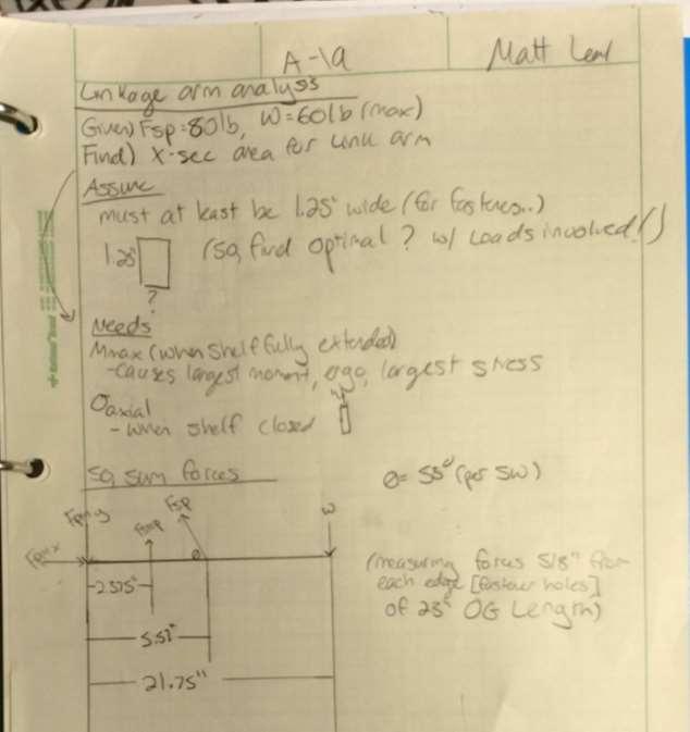
11 This insert will be bolted onto the side wall of the existing cabinet (Appendix B-1) through a mount block. The shelving insert itself will consist of two shelves, each spaced 8 1/3 inches apart. Using statics and strengths calculations to determine cross-sectional area and material selection, the 23 linkage arm will be bolted onto the shelves on one end, and the mount plate on the other (Appendix B-2). The attachment methods for the linkages to the body MUST allow for free rotation so the device motion can take place uninhibited. The device will be mounted to the body of the cabinet using mounting plates, which will be attached to the sides of the cabinet walls. In order control the descent speed of the shelf insert as it lowers into position, a gas spring will be specified and attached to the linkage arm, which will allow for it to assist the user in bringing a shelf into the upright position. This will work very similarly to how many gas springs are applied into the automotive industry, which is to apply a constant force through the duration of the stroke opening on the gas spring. This will be crucial in calculating the forces involved as the linkage arm swings. However, unlike the average trunk-holding gas spring, the gas spring used in this device will be a traction gas spring. Traction gas springs work the opposite way a normal gas spring does, as the natural force tends to want the spring to close, or pull-in (Figure 3). Figure 3: Forces in a Traction Gas Spring The device is stopped by a stop peg, or in this case, a bolt, and will use a slide to keep the gas spring from pulling up an empty shelf at an unwanted time. Both the stop and the slide will be mounted to the mounting plate will be on the mounting plate (Figure 4).
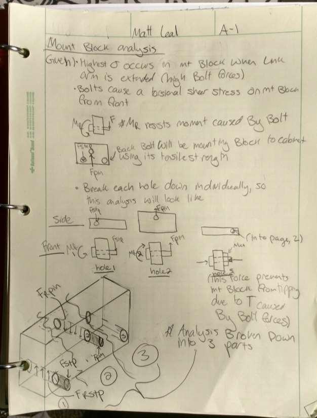
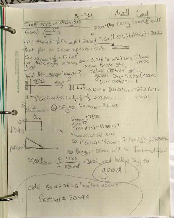
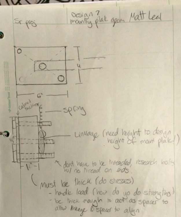
12 Figure 4: Basic Layout of Mount Block Assembly The slide, which is a clevis pin this case, allows the user to freely slide the pin back and forth, whilst being held in place by the cotter pin. The mount plate, or mount box, acts as more of a spacer between the cabinet wall and the shelf insert. It also helps compensate for the forces acting on the forces caused by the shelf weight. This space is necessary to allow enough space for the spring to hang directly over the linkage arm. As the spring will be in the realm of 1 OD, it made sense for the mount plate to be slightly over 1 thick. The width and height of the mount plate were determined through geometric decision making so that the pin stop, and the swivel pin, would have sufficient space. Due to this, the height and width of the mount plate are 6 x 3 The mount plate will have two bolts going through it, bolting the mount plate to the cabinet wall, along with a swivel pin, and the slide. The bottom bolt, acting as a stop for the linkage arm, the middle pin acting as a swivel, in which the linkage arm will rotate about, and the top bolt helping hold the load that the entire system puts on the mount plate. (Figure 3). The shelf insert itself consists of two shelf walls, which are to be made from 1/ aluminum sheet metal, as per the strengths calculations seen in Appendix A-16-18, will be screwed onto the shelf walls with two #4 machine screws (two to each wall, on each shelf side, eight total). After considering the strength equations applied in Appendix A-14-15, it would make sense to also make this shelf, then, out of the same thickness and alloy However, as the shelf needs to be thick enough to accommodate #4 sized machine screws, a thickness of ¼ was chosen.
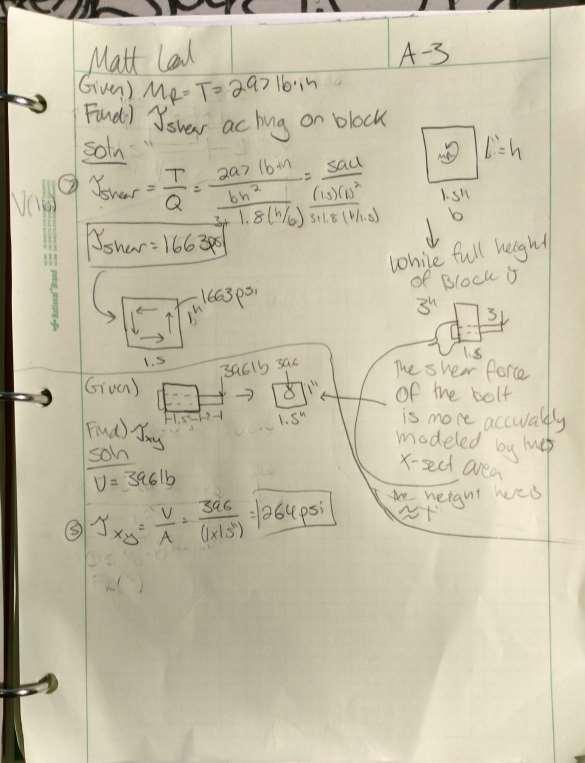
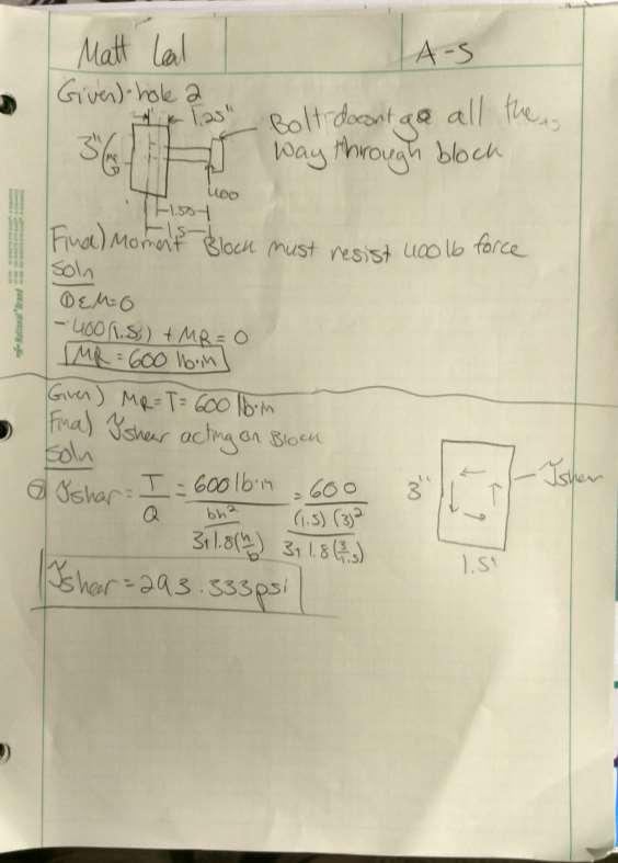
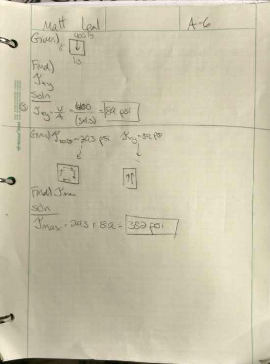
13 Performance Predictions The analyses provided in Appendix A 9-13 prove that the gas spring will assist the user in pushing the shelf up, and even dampen it on the way down. The force the user must use to operate the system can be seen in Appendix A These predicted forces will be within +/- 10% of the actual forces that will be used upon testing of this device (if estimated force is 100#, the actual force will be in the range of 90#-110#). This will indicate a successful analysis, and will signify the correct choice in gas spring. Another very simple test that can determine whether or not the correct material and geometry were used for the loads involved. One can measure any sort of deflection in the load bearing linkage arms when at full load. If there is any deflection, then the load has breached the yield of the material, which is a failure in terms of this load bearing application. Description of Analyses In order for this project to achieve success, there are a few analytical aspects that must be solved early on. They can be broken down as such: Statics and Strengths on the linkage arms to determine linkage material and dimension o Summate forces in X & Y, along with moment (Equations 1,2,3) (1) M = 0 (2) F(y) = 0 (3) F(x) = 0 o Shear and moment diagrams. o Axial Stress (6) σ = Force/Area o Shear Stress (5) τ = V/A o Bending Stress (4)σ = Mc/I o Torsional Stress (non-circular cross section) (7) τ = T/Q Statics and Strengths on mounting block to determine material and dimensions o Summate forces in X & Y, along with moment (Equations 1,2,3) (1) M = 0 (2) F(y) = 0 (3) F(x) = 0 o Shear and moment diagrams. o Axial Stress (6) σ = Force/Area o Shear Stress
14 (5) τ = V/A o Bending Stress (4)σ = Mc/I o Torsional Stress (non-circular cross section) (7) τ = T/Q Statics and Strengths on fasteners to determine and spec necessary fastener sizes o Summate forces in X & Y, along with moment (Equations 1,2,3) (1) M = 0 (2) F(y) = 0 (3) F(x) = 0 o Shear and moment diagrams. o Shear Stress (5) τ = V/A o Bending Stress (4)σ = Mc/I Statics and Strengths on Slide o Summate forces in X & Y, along with moment (Equations 1,2,3) (1) M = 0 (2) F(y) = 0 (3) F(x) = 0 o Shear and moment diagrams. o Shear Stress (5) τ = V/A o Bending Stress (4)σ = Mc/I Statics and Strengths on Insert o Summate forces in X & Y, along with moment (Equations 1,2,3) (1) M = 0 (2) F(y) = 0 (3) F(x) = 0 o Shear and moment diagrams. o Axial Stress (6) σ = Force/Area o Shear Stress (5) τ = V/A o Bending Stress (4)σ = Mc/I o Torsional Stress (non-circular cross section) (7) τ = T/Q Determine necessary min/max force spring must exert on the system to allow for descent, but also to help the user push the shelf up. This uses equation 1 to sum moments about the linkage arm pin. This will show the force the user must exert on the system to overwhelm the natural moment caused without the stop bolt. o Summate forces in X & Y, along with moment (Equations 1,2,3) (1) M = 0 (2) F(y) = 0
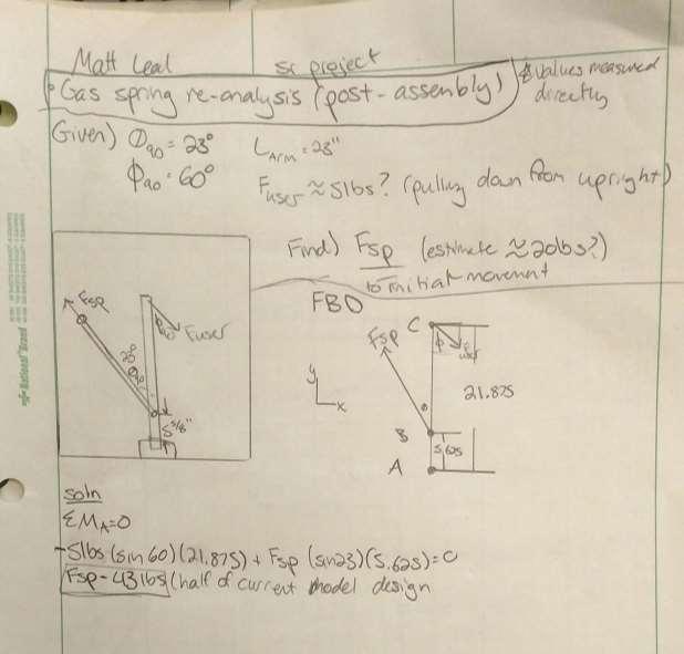
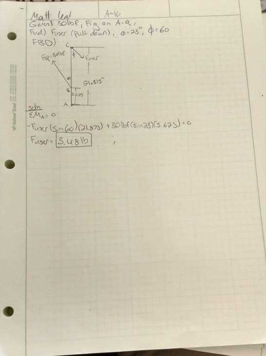
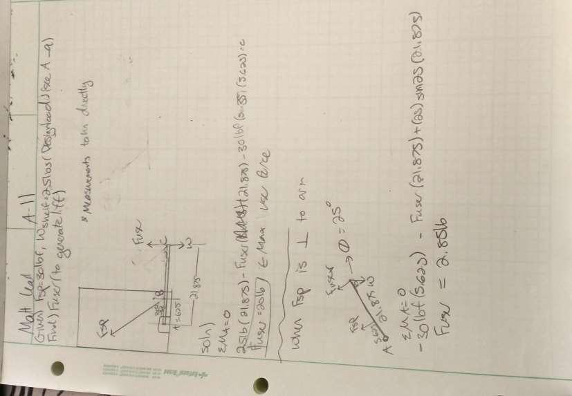
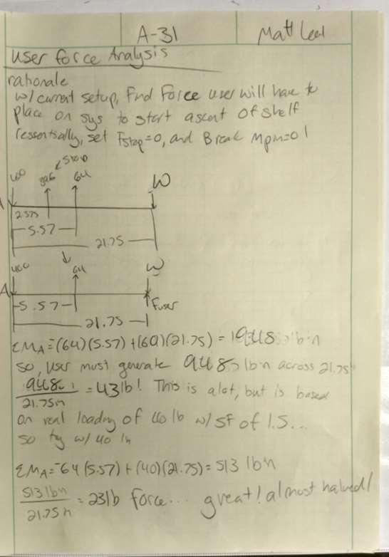
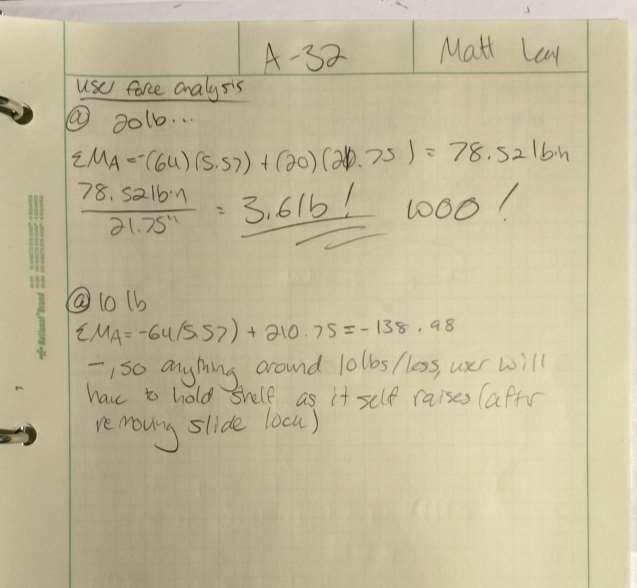
15 (3) F(x) = 0 o Spring force < Weight (in terms of moment about swivel point) (Appendix A 4-8) User force analysis o Determine how much force user must use to push up various loadings of the shelf (1) M = 0 Analyses Gas Spring Speccing Upon summating forces with the max load in Appendix A 4-8, it was determined that the spring force must always be less than 226lbs to allow for rotation. The next step to speccing a spring was inputting the various forces of each model, and choosing the one that was high enough to help dampen the descent/raise the shelf, but also not low enough to barely make a dent on the systems descent speed. As can be seen in Appendix A 9, a rough estimate of the users force of 5lbs was chosen as a target force for the user to have to generate to pull the device down. In order to achieve that, a spring force of 43 lbs was needed. However, upon searching for traction gas springs, the only available model was a 30lbf gas spring. A second analysis, using the 30lbf gas spring was completed to find the new user forces that would be necessary to pull down and push up a shelf at full load. In Appendix A 10, using the new 30lbf, the user will only have to generate 3.48lbf to initiate the descent of the shelf, and will require around a 20lbf push to initiate the gas spring at full load. However, due to the angle at which the gas spring acts on the link arm, this user force quickly decreases as the load moves up, to a low of 2.85lbf, well below the 50% threshold, as seen in Appendix A-11 and A-12. User Force Analysis A unique user force analysis was created in order to model how much force the user would have to put onto the system in order to close it, based on a specific load on the system (Appendix A 31-33). This user force was modeled by finding the moment the user would have to put on the system set the moment to zero. Once the user generated a force larger than said force, the system would begin to accelerate upwards. And, as the angle of the gas spring is at its most perpendicular to the linkage arm when the shelf is in its extended position, it will provide the greatest assist to the user. At the nominal weight of around 15lbs, the user will only have to generate 3.6lbf to trigger the ascent of the system. This is a huge success, as it cuts the users force input by 5x (Appendix A-32).While speccing out the gas spring for this purpose, and poor communication from the manufacturer, there is some doubt that the gas spring will mount to the back of the cabinet so as the angle in which the spring force acts on the link arm is exactly the same angle used in these calculations. There are discrepancies with the way the fasteners will fit, the angle at which they will rotate, etc. These are things that will be cleared up upon the assembly. The exact angle can be more accurately measured once the assembly is fully put together. At that point, the calculations will be done with a more exact angle, which will tighten up the accuracy of this analysis. Linkage Arms
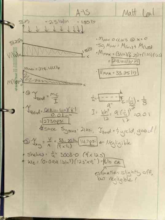
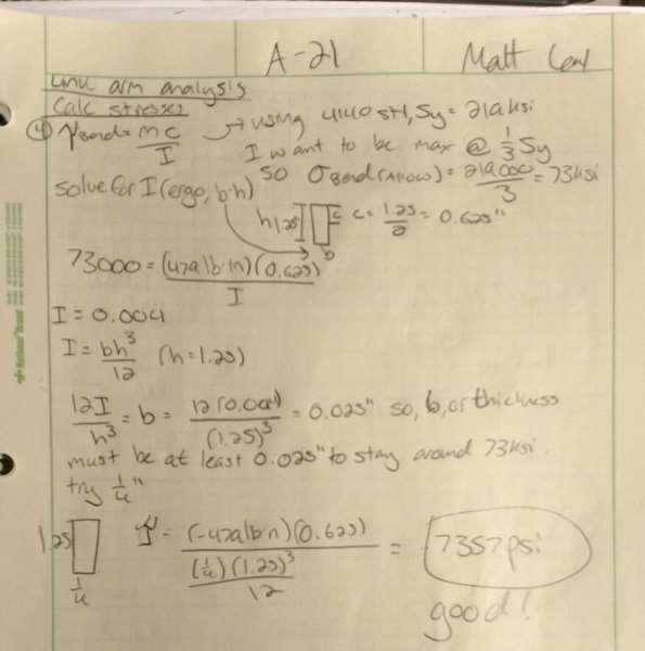
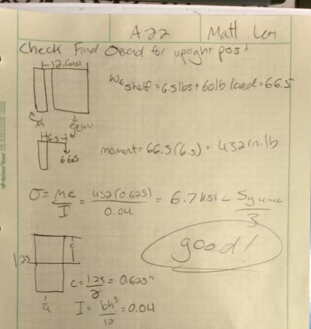
16 With the spring force now clearly identified, it was possible to summate forces, and do statics and strengths equations for the linkage arms in both the extended and retracted positions. These two positions were chosen, as the retracted position will put the most axial stress on the system, and the fully extended will put the most bending stress on the linkage arm, as the weight of the shelf is fully perpendicular to the linkage arm. The max stress seen through analysis of both positions was seen as the bending moment (4) in the open position, and the torsional stress caused by the shelf. Combined stresses in this link arm showed this stress, being psi, was the driving factor in the material choice (Appendix A-27). Originally, there was a plan to use 4140 steel for this application, but upon sourcing material, it was clear 1018 was the cheaper, more readily available alternative with very similar mechanical properties.1018 steel was chosen for its very high yield strength. This will ensure there is absolutely no yield in this device, which is essential, as a critical failure of the use of this device could cause injury. Mount According to the Solidworks analysis posted in Appendix A, with the stresses put on the mounting block (Appendix A-8), the mounting block accrues a max stress that still allows for a safety factor of around 70 on the block. This Solidworks analysis can be backed up with the forces found through hand calculation in Appendix A 1-3 Shelf & Shelf Walls In the initial design for this project, shelves were planned to be built from aluminum sheet and plate. As the design called for a 60lb max load, proper strengths analysis of the material was performed in good practice. However, since many wooden shelves serve the same purpose of holding a small number of dishes, and at a fraction of the cost of aluminum, it made a lot more sense from an economic standpoint to manufacture shelves out of wood. Below, the results of the analysis for the aluminum shelves can be seen, which is proof of good engineering practice for a loading scenario such as this. To find the proper materials needed to withstand the loadings of the system, statics and strengths equations were applied to the shelf geometry in order to optimize material choices (Appendix A 14-18). The max stress (4) in the shelves, under max load, was found to be 2.7 ksi (Appendix A 15). This led to the choice of 6061 Aluminum to be used for this shelf s material, as it is around 10x under the max yield of this alloy. The max stress (5) in the shelf walls, under max load, was found to be 2.7 ksi, so the same material choice was made. The same logic applied here as to the link arm and the mount, where only having to source one material type (6061 for both the shelves and shelf walls) was the easier choice. Slide The statics and strength calculations for an empty shelf pushing against the slide were completed in Appendix A The optimal cross-sectional area was decided on after finding a max bending stress (4) that was well under a material s yield. Originally, a turned down piece of aluminum was going to be used for this slide. However, a much easier solution would be to use a clevis pin. A zinc plated low carbon steel clevis pin was chosen
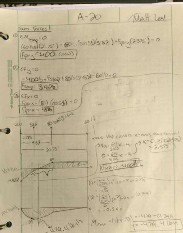
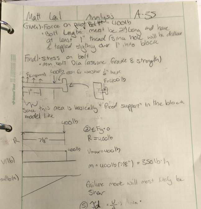
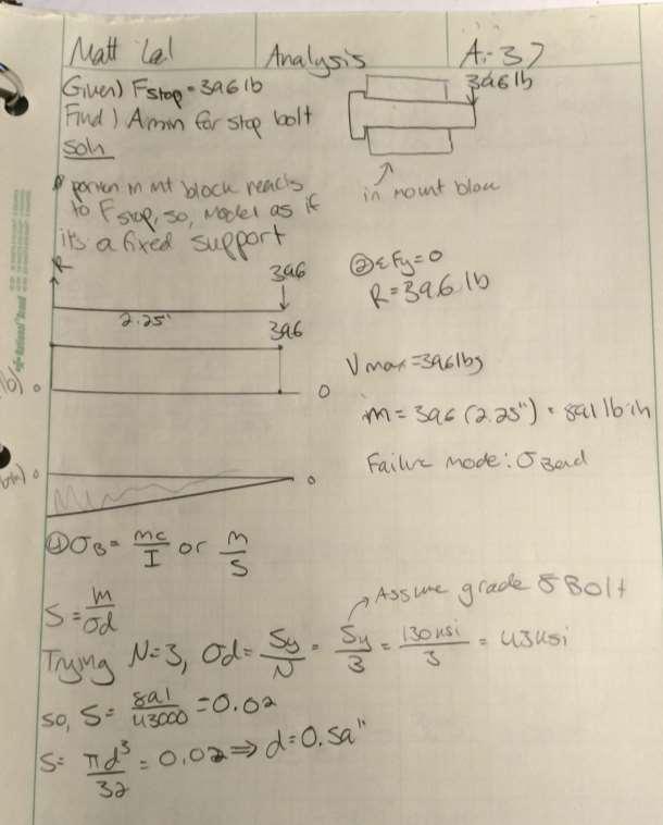
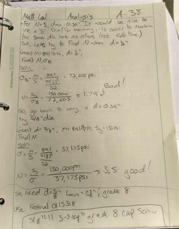
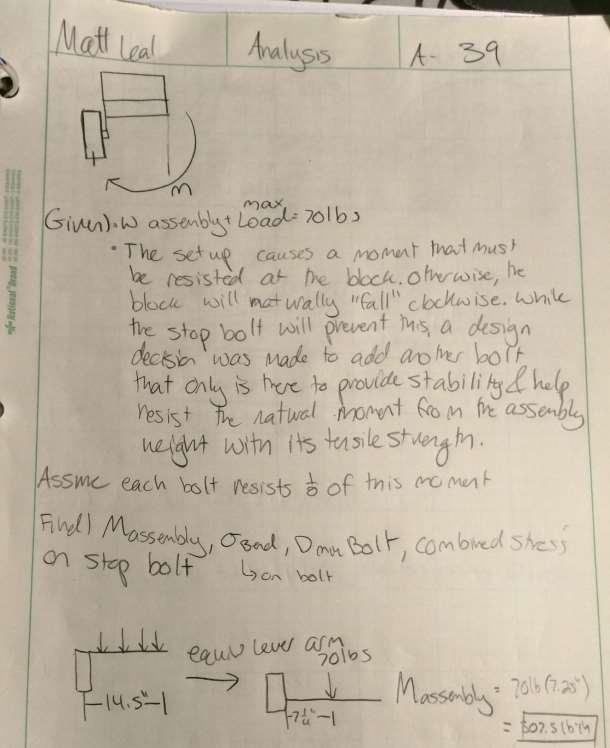
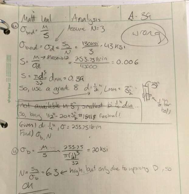
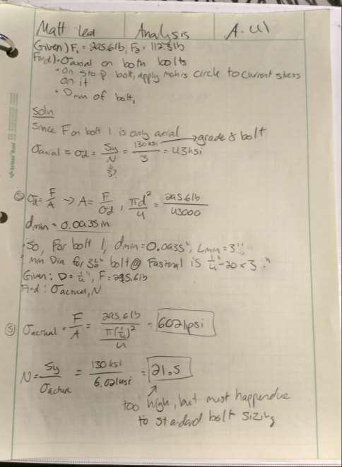
17 for ease of purchase and cost. The analysis in Appendix A page 29 show that the stresses acting on this pin will create a stress that is less than half the yield for the material. This is more than acceptable for this application. Fasteners The analysis of the fasteners for this project were incredibly important, as a large amount of force will be put on both the stop bolt and the swivel bolt. In the fully extended position, there will be close to 400 lbs of force on both of these bolts (Appendix A-20). To accommodate, strengths calculations were used on both bolts in order to find the minimum acceptable diameter necessary to handle these forces. As grade 8 bolts were to be provided for this project free of charge, it was a natural material choice to use for these calculations. After applying strengths calculations to this material based on the forces in Appendix A-20, and an assumed safety factor of three, it was found that the minimum diameter necessary to accommodate these forces was However, in order to have a bolt that stuck into the mount block (threaded portion) and to have a bolt with a machine finished shoulder long enough to allow the link arm to swivel about, a ½ diameter 2 long grade 8 bolt was chosen, as nominal sizes would not allow a small diameter with the proper shoulder lengths. Reapplying strengths calculations to the bolt with a ½ diameter showed a very small 2ksi, which proves this diameter is overkill, but necessary (Appendix A-36). The analysis of the stop bolt proved that a larger diameter was necessary to accommodate the large moment the 400lb force placed on the bolt. After applying strengths calculations, and assuming a safety factor of 3, a minimum diameter of 0.59 was found to be required for this application (Appendix A-37). A 5/8 diameter bolt was chosen for this application, leading to a safety factor of 3.5 for the loads in play here. This setup caused a moment that must be resisted by the mount block. If not, the mount block would naturally tip over clockwise. To prevent this, a design decision was made to add another bolt that is there to provide stability and resist said moment using its tensile strength. The magnitude of the moment, and the ratio both the stop bolt and this bolt resist said moment, can be found in Appendix A-39,40. In order to resist this moment, a minimum diameter for this bolt was found to be However, in order to find a standard bolt that is long enough for the application here, a ¼ diameter grade 8 bolt was chosen, causing a rather large safety factor of 21.5 (Appendix A-41). With the new found axial force on the stop bolt after the previous analysis, a mohrs circle analysis was placed on the stop bolt, as it now contained shear and normal stresses (Appendix A-42). Even with the new found axial loading, there will still be a safety factor of 3.46 on this bolt. Force analysis was necessary in order to find the minimum diameter of the machine screws necessary to screw the shelf onto the shelf walls (a weld was possible, but if this were to be a consumer product, it d have to come in a small package, and be assembled in this way). At this point, the decision was made to have a screw with at least ¼ of length to be able to go all the way through the shelf wall, and into the shelf a decent amount. While a very small minimum diameter was found to be necessary, a much larger diameter screw will be used, as otherwise, it would be very difficult to drill and tap a hole smaller than a #4 hole (Appendix A-34). Because of this, a #4-40 screw will be used to mount the shelves to the shelf wall.
18 A word on steel alloy choice The analyses in this report were made with 4140 steel in mind; an arbitrarily chosen grade of steel to predict the safety values (N) that the stresses placed on both the linkage arm and mount block. However, upon sourcing materials for these parts, it was clear that 1080 cold rolled steel was much cheaper, and much easier to source more specific stock that would meet the requirements for this project. The yield strength of 4140 is 60,200 PSI, and the yield strength of 1080 cold rolled is around 70,000 PSI. Since these two yield strengths are so similar, and in fact, the new material choice has a higher yield strength, it is the clear decision that this last minute material switch would be more than appropriate for these two parts (AISI 1018 Steel, Cold Drawn). A word on aluminum alloy choice The analyses in this report were made with 3003 aluminum in mind, which also was arbitrarily chosen grade of Aluminum which allowed the ball-parking of safety values (N) for the stresses placed on the shelves and shelf walls. However, upon sourcing materials for this project, it was clear that 6061 was both cheaper and more readily available for the intended use in this device. The two yield strengths for 3003 and 6061 are different, as 3003 has around an 18ksi yield, and 6061 has a much higher yield of around 40ksi according to Matweb. This last minute decision to switch to 6061 has simply doubled the safety factors involved in the design of the shelves and shelf walls. As this might call for a redesign, the ¼ thickness of the shelf was chosen for fastener mounting purposes, so going for a smaller cross-sectional area would not be an easy possibility. In the future, however, there is a likelihood the 1/8 shelf walls could be reduced in cross-sectional area due to this jump in yield strength, and most likely, a thinner sheet of aluminum could be used. Device: Parts, Shapes, and Conformation This device consists of 1x shelf 1x housing 1x linkage arm 1x gas spring 1x mount plate 1x ¼ x 3 1/2 grade 8 bolt (mount block support bolt) 1x ½ x 2 Grade 8 bolt (swivel bolt) 1x 3/8 shoulder bolt (shelf swivel bolt) 8x washer and nut combos 2x Steel Brackets 1x ¾ square tubing (2ft) All geometry can be seen in of fit and parts can be seen in Appendix B Device Assembly
19 This device consists of the parts listed above. All parts will be secured to one another with the fasteners listed within the appendix. The spring will be mounted to the back of the cabinet, and the other side will be mounted to a hole drilled into the linkage arm Methods and Construction Solution Method This project was designed and analyzed for success at CWU, using the resources available in the MET department. All parts will be manufactured per drawings, which can be seen in Appendix B. Construction In order to achieve the design for this device, the linkage arm, mounting block, shelves, shelf walls, and shelf rods, will all be machined out of raw stock. All of the machining required for this project is all possible in thanks to the machine shop located in Hogue Tech. The gas spring will not be manufactured, and will be purchased through a third party manufacturer. The insert environment itself will be manufactured in the woodshop using scrap wood, as the design of that environment is not within the engineering scope of this project. All of the fasteners, washers, nuts, spacers, and e-clips will be provided as a donation from Fastenal. The mounting block assembly will consist of two bolts, one swivel pin, three washers, three nuts, and one spacer (bushing) to provide the correct spacing between the block and the linkage arm. The slide will then be inserted into the machined hole in the mounting block, and will be secured in with a pin inside the insert environment. This assembly will then be bolted into the design environment, as seen in Appendix B 1-2. To attach the gas spring to the device, two threaded holes will be machined into the linkage arm, as per Appendix B-8, and into the back board of the environment, as both ends of the gas spring have A3 threaded fittings. The shelf will be screwed to the shelf walls with 1/8 machine screws, and will then be fitted to the linkage arm via a swivel pin. The linkage arm will then be fastened to the swivel pin going through the mounting block as can be seen in Figure 5. According to Appendix E, device construction should take around 120 hours. This is due to the large amount of machining necessary to construct the various parts in this system. Also, the construction of the wood environment in a separate wood shop in which I will need to work around times will contribute a lot to that amount of time.
 o One ¼ bolt o One 5/8 bolt o Three washers o One spacer o Two nuts o Slide Linkage")
20 The final construction will resemble figure 5. Renderings Figure 5: Constructed Device. Current renderings for all parts can be found in Appendix B The parts will consist of the following: Mounting block assembly o Mounting block o Swivel bolt (1/2 x 2 Grade 8) o One ¼ bolt o One 5/8 bolt o Three washers o One spacer o Two nuts o Slide Linkage arm assembly o Two washers o Swivel bolt (Shoulder Bolt) o Two Nuts o One spacer o Gas spring fastened to hole (Appendix B-32)

21 Shelves Housing Operation The device will begin in its closed state, meaning the linkage arm will be perpendicular to the bottom of the cabinet environment, and the shelf will be fully inside the environment. To begin the descent, the user will pull down on the handle on the bottom shelf. This will begin the gas spring-damped descent of the shelf. Once the shelf is stopped by the stop pin/ bolt, the descent is complete, and the device is in its opened state. At this point, the user will push the slide into place, effectively locking the device. Once the user is done loading/unloading the device, the slide can be removed, and the gas-assisted shelf can be pushed back upwards into the closed state. Post Manufacturing Discussion, issues, and successes. Overall, the manufacturing for this project was estimated to be around 23 hours, and ended up being around 38 hours, nearly double the original estimate. This was due to the excessively long amount of time dedicated to machining the mount block correctly. Mount Block During the machining operations seen on the mount block, the threaded hole was threaded in the wrong direction through the mount block, after all four holes had already been machined. Below, the hole layout for the mount block can be seen in Figure 15. Figure 15: Mount Block hole layout To machine the stock for the mount block down to the correct thickness, a lot of material had to be taken off. By hand, this would have taken many hours of painstaking precision and effort. Instead, a CNC Mill program was written to perform the necessary face milling. A copy of the written program can be seen in Appendix X. This program was run many times, each time with the Z height offset changed to cut to the correct depth. By running this program 10 times, it took the correct amount of material off the part. Figure 16 shows the mount block during the CNC milling operation.


22 Figure 16: CNC Mill Op Shelves and Housing The manufacturing of the shelves was quick and painless, using wood glue and a nail gun to fasten the wood together. This was much cheaper and faster than the original plan to manufacture the shelves from aluminum. Figure 17 shows the stock wood used to create both the shelves and the housing. Figure 17: Housing and Shelf stock Future Improvements There are many improvements that can be made to the manufacturing process to improve efficiency and make the entire process more lean. For example, a CNC program could be written to face mill the stock down to size for the mount block, and then drill the holes. This would not be a time-consuming program to write, and would save hours on the manual drill press.
23 Purchasing the correct stock would also save an immense amount of manufacturing time, as if the correct stock with the correct thickness were to be purchased, an entire manufacturing step could be skipped. Testing Method As per the user force analysis described in the Introduction, the force the user needs to begin the shelf descent must be cut in half. This will be a little tricky to measure, but can be done simply with a scale (spring scale), which will be placed between the user force (users hand) and the shelf bottom. When the user pushes up on the scale, it can be read as soon as the shelf starts moving, indicating the force placed on the shelf for it to begin descending. This force must also come within 10% of the predicted force needed to raise the device to be able to be considered a success (Appendix A 31-33). Appendix H has full details on the testing on this device. Scope of Testing The testing required to determine whether or not the current design is a success will be compared to the requirements seen below Requirements o Must hold a nominal weight of 15#, and a max weight of 30# o Must lower highest shelf between to bottom of cabinet space. o Must fit into a standard 27 x 16 x 11 cabinet space o Entire unit must weigh less than 30# without load o Must have a safety factor at least 1.5 on strengths of linkage arms o Must assist user needed force to raise nominal load by at least 50% TEST 1 The first test that will be conducted will compare the predicted user force input necessary to raise and lower the shelf with the nominal loading. The predicted forces involved in the operation of this device are 3.48lbf to lower the shelf, and 2.85lb to raise the shelf. These forces are indicative of the forces used to overwhelm the moment caused by the gas spring, so this force will cause the moment to become zero. Due to this, to generate movement, the forces involved will be very slightly higher than the predicted values dependent on how fast the user moves the shelf. Data will be acquired with a spring scale, which will be attached to both the shelf and the user s hand, and will measure the force generated by the user. Resources (hard/soft/external, people, costs),
24 The procedure and resources necessary for this test will be very simple and straightforward. A spring scale will be needed to capture the data. Four 5lb weights will simulate the optimal loading scenario for the shelf. The shelf s housing must be mounted to a table for the shelf not to flip over, but in this case, an assistant will simply hold the shelf in place, to prevent tipping. The procedure will cost nothing, as CWU MET has all the materials necessary. data capture/doc/processing Data will be captured in the table below. TOP LOADED TOP LOADED TOP LOADED TOP LOADED TOP LOADED TOP LOADED TOP LOADED TOP LOADED TOP LOADED BOTTOM LOADED BOTTOM LOADED BOTTOM LOADED BOTTOM LOADED BOTTOM LOADED BOTTOM LOADED BOTTOM LOADED BOTTOM LOADED HALF/HALF HALF/HALF HALF/HALF HALF/HALF HALF/HALF HALF/HALF TRIAL WEIGHT (lb) F_UP (lbf) F_DOWN (lbf)
25 WEIGHT F_UP AVG (lbf) F_DOWN AVG (lbf) Test procedure overview The user will place both ten pound weights into the shelf, and proceed to pull the shelf down, and record the data. The user will repeat the same thing for pushing the shelf up into its start position. Precision and Accuracy The force will be ever changing as the user operates the device. The highest force is recorded by the spring scale, so the highest force that occurs during device operation will be measured. Test 1 Procedure Summary/overview The user will place both ten pound weights into the shelf, and proceed to pull the shelf down, and record the data. The user will repeat the same thing for pushing the shelf up into its start position. Time and resources There are three trails involved in the testing of this requirement. This will take an estimated minutes total to test the device, and collect the data. This test will require the following A surface to mount the housing to. A spring scale measuring to the nearest lb. Four five-pound weights A protractor
26 Specific actions to complete the test, 1. Fasten/Hold down the housing to prevent movement during testing. This can be done by clamping down the mounted brackets on the back to at table. Use 2 C-clamps to do this. 2. Attach the 5lb weight to the spring scale and note any discrepancy in the spring scales weight readout. 3. Attach the spring scale to the handle on the shelf 4. With the shelf unloaded and in the upright position, pull the spring scale to initiate movement of the shelf, ensuring the user force is 60 degrees down from the plane parallel to the surface you have clamped the housing to. 5. Once the shelf has been lowered all the way, record the max spring scale value shown on the spring scale. 6. Return the shelf to its upright position. 7. Next, begin the top-loaded trial. Load 5lbs weight to the center of the top shelf. 8. In a similar manner to step 3, pull the spring scale to initiate movement of the shelf, ensuring the user force is 60 degrees down from the plane parallel to the surface you have clamped the housing to. 9. Once the shelf has been lowered all the way, record the max spring scale value shown on the spring scale. 10. Zero the spring scale 11. In a natural manner, i.e. pushing the shelf up as you would in a real scenario, use the spring scale to pull the shelf back into its original position. Record the max spring scale value shown on the spring scale. 12. Repeat steps 6-11 with a 10-pound and a 20-pound loading on the shelf. Ensure the weights are evenly distributed along the surface of the top shelf. 13. Repeat steps 6-11 one more time for a second trial, 14. Begin the bottom-loaded trial. Repeat steps 6-13, but load the weight onto the bottom shelf. 15. Begin the half/half trial. Repeat steps 6-13, but load the weight equally between the two shelves. i.e. for the 10-pound trial, put one 5lb on the top shelf, and one 5lb on the bottom shelf. *note, skip the 5lb trial for half/half* 16. Remove the gas spring from the device. 17. Using the half/half loading strategy outlined in step 15, repeat steps 6-13 without the spring attached. *WARNING* Without the spring, the shelf should descend very quickly. Safety This is a safe test, and since it s at the optimal weight, and not the designed safety max, it should be fine. However, ensuring the shelf is properly mounted to the test surface is crucial.
27 Deliverables Keeping the housing mounted proved to be difficult with the higher weight tests. A new mounting design should be accomplished before the next test. Averaging all loading scenarios, without load, the user must exert a force of 0lbf raising the shelf (gas spring has enough power to raise the unloaded shelf), and 8lbf lowering the shelf. At the nominal max load, the user must exert 12.7lbf to raise the shelf, and 14.4lbf to lower it. This is much higher than originally predicted, possibly due to the amount of friction and interference the shelf has in all its moving parts. With only one arm, this problem is huge. The implementation of a second arm should help clear this up slightly. As can be seen in the User Force V Load diagram in the report appendix, at higher loadings, the discrepancy between predicted and measured forces increases dramatically. This is undoubtedly caused by the difficulty in raising and lowering the shelf due to the torsion that is put on the link arm. Overall, the measured forces up were much higher than predicted, and the measured forces down were much lower, both by about a factor of two. There could be a major error in prediction analysis. In order to bring forces to a much more manageable place, a stronger gas spring could be implemented. However, after testing with a 40lbf spring as opposed to the current 30lbf, it has been deemed too dangerous. While an unloaded shelf is locked into place, the 40lbf spring is so powerful that it would snap the whole shelf upward in a violent fashion. Test 1 report appendix.
28 Force (lbf) User Force (lbf) User Force V Load Measured Force Up Predicted Force Up Measured Force Down Predicted Force Down Load (lbs) Predicted Vs Measured Forces (UP) Predicted Up Actual Up Force Load (lbs)
29 Force (lbf) Measured Force V No Spring Force (UP) Load (lbs) Measured Up No Spring Up TOP LOADED TRIAL WEIGHT (lb) F_UP (lbf) F_DOWN (lbf) TOP LOADED TOP LOADED TOP LOADED TOP LOADED TOP LOADED TOP LOADED TOP LOADED TOP LOADED BOTTOM LOADED BOTTOM LOADED BOTTOM LOADED BOTTOM LOADED BOTTOM LOADED
30 BOTTOM LOADED BOTTOM LOADED BOTTOM LOADED HALF/HALF HALF/HALF HALF/HALF HALF/HALF HALF/HALF HALF/HALF WEIGHT F_UP AVG (lbf) F_DOWN AVG (lbf) Measured WEIGHT F_UP AVG (lbf) F_DOWN AVG (lbf) No Spring WEIGHT F_UP AVG (lbf) F_DOWN AVG (lbf) Predicted TEST 2 At the time of the second test, a second link arm was to have been installed. However, due to shipping error, the part did not arrive in time. So, the second test consisted of a deflection test of the original link arm. The link arm will be loaded to its max weight, a simple material yield check will be performed, and a deflection measurement will be taken.
31 The procedure and resources necessary for this test will be very simple and straightforward. A dial indicator mic will be necessary to measure the deflection, along with 60lbs of weight. As the mount block will be removed from the housing, clamps will be necessary to mount the block to a work surface. In general, this test would best be replicated in a lab/shop environment. Data will be captured in the table below. TRIAL PREDICTED LOAD (lbs) DEFLECTION (in) Test 2 Procedure The user will place 60lbs of weight on the tip of the link arm, on top of the hole where the shelf would normally be mounted. The user will then measure deflection of the tip with the dial indicator. Precision and Accuracy The dial indicator involved MUST read to the nearest To ensure accuracy, there will be three trials. The deflection must be measured to the nearest The average deflection will be compared to the predicted deflection in an excel type chart. C clamps Test Weight
32 Mount Block Dial indicator Figure 18 Time and Duration There are three trails involved in the testing of this requirement. This will take an estimated minutes total to setup, test the device, and collect the data. Resources This test will require the following A surface to mount the block to 2x C clamps 1x dial indicator mic 3x 20lb weights Specific actions to complete the test 1. Remove mount block and link arm assembly from the housing completely. 2. Mount the block on a flat surface and extend the link arm to the down
33 position (fig 18). 3. Ensure the tip of the link arm is hanging off the flat surface so the dial indicator can rest below it (fig 18) 4. Use 2x Clamps to mount the block to the table (fig 18) 5. Mount the dial indicator directly perpendicular to the link arm (either above of below, whichever is most convenient) (fig 18) 6. Pre-load the dial indicator on the tip of the link arm underneath the shelving mount hole (fig 18) 7. Zero out the dial indicator 8. Slowly load the 60lbs weight above the shelving mount hole (fig 18) to ensure no catastrophic yield. 9. Once loaded, record the readout on the dial indicator to the nearest Repeat steps 6-9 two more times to complete three trials. Safety There is a possibility that if the mount block is not properly secured to the test surface, the block may dismount from said surface. To ensure proper safety, begin loading the 60lbs slowly, and see how the testing setup reacts. Deliverables: Upon measuring the deflection of the tip of the link arm, a very large discrepancy between the predicted deflection and the actual deflection is seen. This is due to a lot of unforeseen error in the original testing technique. As can be seen in figure 1, the surface which the block is mounted to hangs off the base of the table. This probably accounts for some of the deflection seen. Also, the back pin on which the arm swivels is smaller than the hole in which it rests i.e. there is a lot of clearance. Due to this, there is a lot of play involved, so when the weight is applied, some of the deflection is not necessarily material deflection, but just movement of the entire arm in general. For better results, this test will be recreated once the second link arm is installed. Report Appendix: TRIAL LOAD (lbs.) DEFLECTION (in)
34 PREDICTED Spring Rework Phase (Iteration 2) In order to address the issues that were prevalent after the initial build during the winter, a rework period was implemented throughout spring. Figure 19 details the planning and design phase for a second linkage arm to be added to this design. Although it did contradict the original design goal of only a single arm, it was decided to be absolutely necessary for the success and safety of the device. The overall goals of Iteration 2 of this project were as follows. Eliminate deflection when upright Eliminate torsional deflection when extended Keep shelf parallel to ground during actuation Optimize all part connections for rigidity Design and Analysis of Link Arm 2 The overall idea of the implementation of this link arm was to eliminate deflection when upright, torsional deflection when extended, and to keep the shelf parallel during actuation. Placing the second link arms rotational axis non-concentrically to the first would be the responsible factor for now allowing the shelf to rotate freely during descent. The axis of the second link arm can be seen in figure 19.
.")
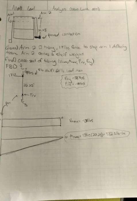
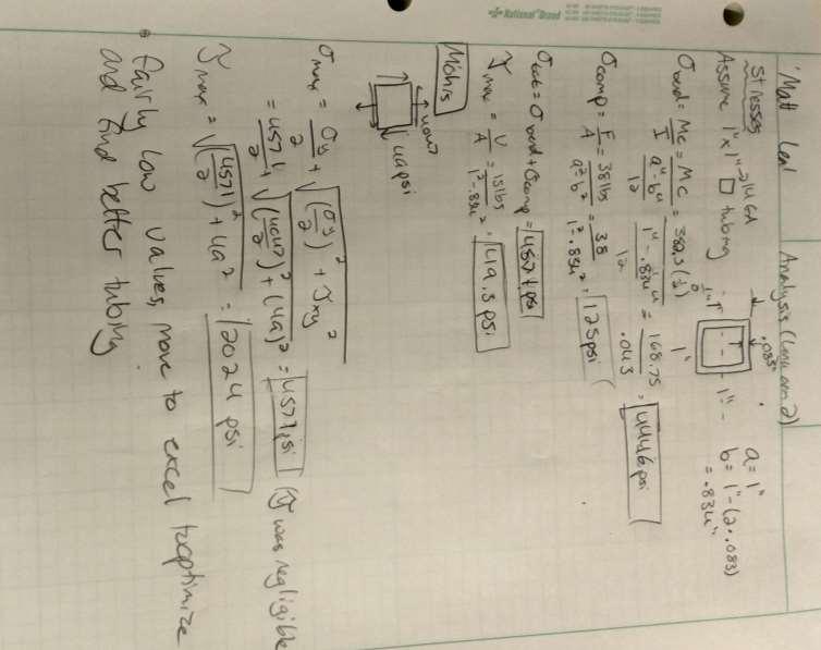
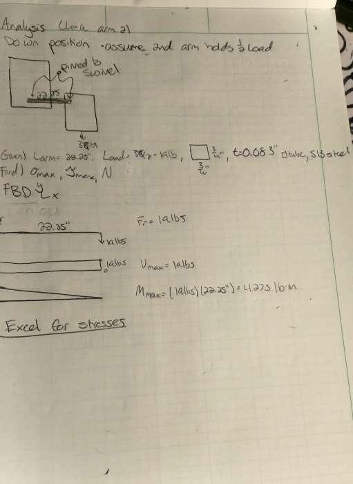
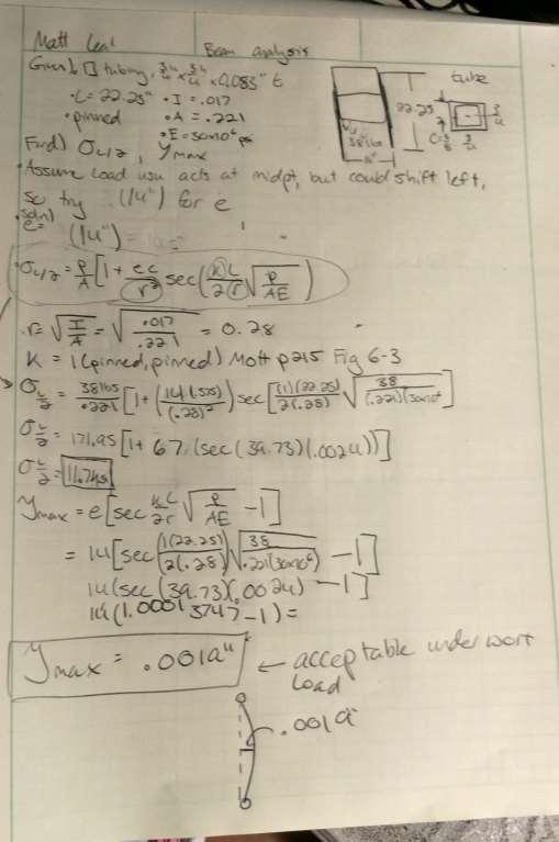
35 Figure 19 As there would be forces acting on this arm in two directions (i.e. across both sides of the cross-section), a square tubed cross-section was chosen for easier stress analysis and rigidity in both directions. In order to get a general idea of how much stress would be placed on this arm during actuation, the shelf was loaded to its max weight in both upright and downright positions (figure 20). The shelf was then pulled to eliminate deflection in the first arm. This simulated the amount of force the second arm would have to be able to endure to eliminate the deflection in question. The second form of analysis came from viewing the upright loading as an eccentrically loaded column. To ensure that the second arm would not fail, or endure too much deflection, it was modeled as if the first arm was not acting on the system (Appendix A A-43-46). A ¾ x ¾ x.083 (thickness) steel square tube was designated and implemented.

36 Implementation Figure 20. After the implementation of the second link arm, the change was drastic. The deflection seen in the original design was almost null. Even with weight loaded, as can be seen in figure 10, the shelf walls remain essentially parallel to the housing walls. This was a tremendous success. Figure 21 shows the implemented dual link arm and its effectiveness in keeping the shelf parallel. While it did help, the loose connections between part connections still allowed for some play between the shelf and the arms. The theoretical ability for the shelf to be kept parallel during actuation of the device was tested upon implementation of the arm. The shelf was still able to move close to 15 degrees in both directions (from parallel) due to the soft connections between all the parts. However, this was still a huge improvement and another large step towards the goal of zero degrees of freedom during actuation.


37 Figure 21 Connection rigidity To improve the overall rigidity of the system, brackets were machined and implemented to this device. These connections, now strengthened by steel brackets, performed much better than before (Figure 22). Figure 22
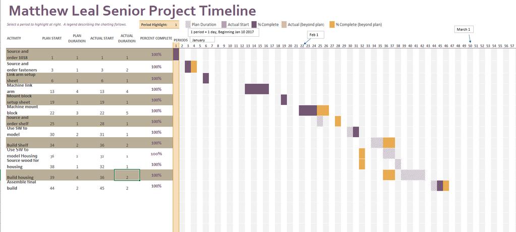
38 Budget/Schedule/Project Management Managerial Approach Assuming all R&D is complete, and only the manufacturing is required, every part will be manufactured in the order that makes sense. This means that parts that join together (i.e. pins through holes, etc) will be manufactured around the same time to ensure fit, so the manufacturer will not have to go back later, re-set up machines, and fix the issues. This means if a pin is meant to go through a hole, the pin will have already had to be made, so that while the hole is being manufactured, an active on-site test will be done to ensure fit. If there are any issues, the manufacturer will be able to fix the issue with the current machine set up. Cost and Budget A parts list can be seen in Appendix C, which details description. Sources and costs can be seen in Appendix D. Some parts will be donated by various companies. For example, Fastenal will be providing all fasteners, nuts, and washers that will be needed for this project. These will be completely free of cost. The cost of this project will be supported by the designer completely, aside from those pieces being donated, or any material which may be found to be in excess in the MET department. Labor costs are estimated to be minimum wage in WA ($9.47/hr), and with labor being estimated at 120 hours, total labor costs will be $ The total cost of this project is estimated to be around $1400 (with labor), and around $150 without. Schedule The current schedule for design, build, and testing, can be seen in Appendix E. The total predicted time for project completion is around 287 total hours. Throughout Fall and Winter quarter, the project was ahead of schedule. Build quarter went by very quickly, with an overall time spent in the shop of 38 hours. This was slightly larger than expected, and came because of difficulties machining the mount block. Spring quarter, the project quickly fell behind schedule once the need for rework and Iteration 2 became apparent. This was unforeseen in the time estimation for spring quarter, and tacked on around 20 extra hours onto the project. Overall, this project took 43 hours during spring quarter.
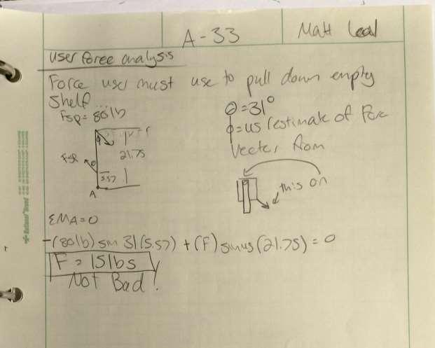
39 Discussion Project Progression Throughout the development of this project, the main design changed many times. Upon careful inspection of the benchmark for this design, the first design consisted of two link arms, with one on each side of the shelf unit. However, this would ve required two gas springs in order for no torsional stresses to build in the link arms due to the gas spring force. Looking through prices of gas springs, the design goal turned into being able to create the device with only one link arm, and in turn, only one gas spring. This, however, turned into a very large struggle, as having only one link arm caused a large amount of torsional force to build on the link arm and the mounting block. While it was difficult to account for the complex combined loading caused by this one-armed setup, it cut the costs greatly by only needing one link arm, one mount plate, and one gas spring. The complex loading, however, has led to some very complex stresses that come into play when the device is fully extended. This caused the need to go to FEA for the mount block. Another issue that has slowed the progress of the project is the seemingly incorrect speccing of the gas spring involved in lowering and raising the device. At first, an 80lb spring was specc d when it seemed reasonable for the user to have to generate close to 15lbs of force to open and close the shelf. Upon testing the device, and the force required to lower the lever arm, it was clear that this theoretical force was much too high for this application. Because of that, a new way of analyzing user input force was used (INPUT CITATION), and thus, a new, much lower gas spring was used. If the correct analysis was used the first time, the project would have been overall cheaper, as multiple springs would not have been necessary to purchase. Successes Overall, there were many successful ideas that came out of the many iterations this project went through. At first, the idea was to use an extension spring to dampen the descent speed of the shelf, along with helping the user push a full load up. This led to countless frustration, as for one, an extension spring would be utterly aesthetically displeasing. The main problem with this idea, however, was the need to track the amount of pull force the spring would be exerting on the system as it was extending, as the force of a physical spring is defined by the length of its extension. This made speccing a spring for this nearly impossible. The eureka moment for this problem came when observing a car trunk being held open by a gas spring. Further research into gas springs led to the choice of a traction gas spring, which has a constant pull-in force, which solved the problem caused by having a physical spring with a constantly changing force. This allowed for a constant force acting on the link arm, which also allowed for all strength calculations for said link arm to be completed with accuracy.
40 Another huge issue that came to mind halfway through the project came from the simple fact that that gas spring pull-in force would always be acting on the link arm. Due to this force, the arm would be pulled up when the shelf was empty (as the load on the shelf usually overpowered this force). After weeks of redesign ideas, the simplest solution became key. Simply, put a sliding stop over the link bar when in its lowered position to prevent any unwanted travel when empty. At first, the stop bolt, the clevis pin slide, and the swivel bolt were originally planned to be turned down pieces of metal. However, upon fastener research, the decision was made to replace these machined parts with fasteners. This eliminated the need for any machining, and provided a very cheap alternative. Learning through design iteration, and the future of this project Towards the end of this project design timeline, there were many design choices made that, in the future, would most likely be revised. The biggest one being the choice of using only one link arm to support the shelf. The torsion caused by this setup was a nightmare to model, and ended up putting stresses on the system that simply could ve been avoided had there been two link arms. In an attempt to save money in material, the design was made less efficient than it could have been. If this device were actually to go into production, the dual link-arm system would be implemented that would greatly reduce the necessary thickness of the mount block, and most likely, the link arms. While it would require more material, and two gas springs, it would simply be much more efficient, and might even save cabinet space, despite the logic that only one link arm system would take up less space than two. The slide lock can easily be improved as well. By adding a spring along the outer diameter of it, it can auto-return to the locked position always. The geometry could also be changed so that the user can simply pull down the shelf, and it ll actuate the slide lock out of the way. Then, the user will simply have to pull the slide back when raising the cabinet. A different way of mounting the block to the cabinet would also be required in a commercial production, as the user most likely would not like to see two giant bolt heads sticking out of their cabinet. The shelf design itself would also most likely be changed to be more aesthetically pleasing, and the shelves would have a lip implemented on them so shelf contents would not fall out of the shelf. However, the shelf aesthetic design was not necessarily in the scope of this project; only the necessary material choices to handle the stresses placed on them. The overall gas spring/rotational analysis was difficult, as the angles that the load and spring forces act on the rotational motion of the link arm are constantly changing throughout the movement path of the arm. This was a tough thing to balance, as a spring that might be great for helping the user push a load up might be too strong, and prevent the user from pulling the shelf down, or even become dangerous as the strong spring force could rip the shelf upwards if not properly locked down, resulting in injury. Per the ASME Engineering Ethics standards, safety is above all, the top priority. Due to this, the effectiveness of the gas spring in raising the load was hindered to ensure that if the user did
41 slip and release an empty shelf from the lowered position, it would not snap up quickly and injure the user. Conclusion At the end of Fall quarter 2016, all research, design, and analysis, are compete for the High Accessibility Kitchen Cabinet Insert. It was crucial to complete all stress analysis accurately to ensure that no part would yield at any point during the operation of this device, as any failure with high weight loads could result in injury to the user. By completing accurate analysis, the correct material and material sizes were chosen with a high level of confidence. While the original critical design requirement of reducing the force the user must exert on the system by 50% at a nominal weight, it appears, according to predictive analysis, this force was reduced by much more than 50% around the optimal weight. This is a tremendous success, but will only be considered true success upon the accuracy of the predicted performance vs. the actual performance. The user force, being the predicted performance value, must be within 10% of the actual user force measured during the testing of this design. If these values do lie within this range, then the project can be measured as a complete success. Acknowledgments This project would not have been possible were it not for the resources and guidance available for reference at CWU. A special thanks to professors Pringle, Johnson, and Bramble for design and analysis help, and the constant feedback necessary for success throughout fall quarter. Matt Burvee was also key in helping guide this project, especially in regard to the use and function of traction gas springs. The feasibility of machining the parts involved in this project were guided by both Burvee and Bramble, leading to many design decisions being changed in regards to machinability. All fastener research and design would not be possible without Steve Leal, regional manager at Fastenal, who provided guidance in special types of fasteners that would be critical in the function of this device. Fastenal also provided all fasteners and fastener accessories free of charge for this project. References Works Cited "AISI 1018 Steel, Cold Drawn." AISI 1018 Steel, Cold Drawn. N.p., n.d. Web. 23 Nov "ASM Material Data Sheet." ASM Material Data Sheet. N.p., n.d. Web. 23 Nov
42 AZoM, Written By. "AISI 1018 Mild/Low Carbon Steel." AZoM.com. N.p., 13 July Web. 23 Nov AZoM, Written By. "AISI 1018 Mild/Low Carbon Steel." AZoM.com. N.p., 13 July Web. 23 Nov AZoM, Written By. "AISI 4140 Alloy Steel (UNS G41400)." AZoM.com. N.p., 11 July Web. 23 Nov AZoM, Written By. "Aluminum / Aluminium 3003 Alloy (UNS A93003)." AZoM.com. N.p., 11 June Web. 23 Nov "Gas Springs." Gecea RSS. N.p., n.d. Web. 23 Nov. "7 Things to Consider When Choosing an Aluminum Grade Metal Supermarkets." Metal Supermarkets - Steel, Aluminum, Stainless, Hot-Rolled, Cold-Rolled, Alloy, Carbon, Galvanized, Brass, Bronze, Copper. N.p., 09 May Web. 23 Nov. "What Aluminum Grade Should I Use? Metal Supermarkets." Metal Supermarkets - Steel, Aluminum, Stainless, Hot-Rolled, Cold-Rolled, Alloy, Carbon, Galvanized, Brass, Bronze, Copper. N.p., 09 May Web. 23 Nov "Rev-A-Shelf ''Premiere." N.p., n.d. Web. 23 Nov "Section Modulus Equations and Calculators Common Shapes." Engineers Edge - Reference Data for Engineers. N.p., 05 Mar Web. 23 Nov Springs, Industrial Gas. "Calculating Gas Spring Sizes - Industrial Gas Springs." Calculating Gas Spring Sizes Industrial Gas Springs. N.p., n.d. Web. 23 Nov Springs, Industrial Gas. "Damped Gas Spring - Industrial Gas Springs." Damped Gas Spring Industrial Gas Springs. N.p., n.d. Web. 23 Nov , Page 1 Of, 2016 Date: November 16, Rev-03, and Strip.bo.hki. Product Standard Socket Head Shoulder Screws, Knurled Head, Black Oxide (n.d.): n. pag. Web. Appendix A Appendices
43 A-1
44 A-2
45 A-3
46 A-4
47 A-5
48 A-6

49 A-7

50 A-8
51 Simulation of Mounting Block Date: Saturday, November 12, 2016 Designer: Solidworks Study name: SimulationXpress Study Analysis type: Static Table of Contents 35 No Data Description

52 Assumptions Model Information Solid Bodies Document Name and Reference Boss-Extrude3 Treated As Model name: Mounting Block Current Configuration: Default Volumetric Properties Document Path/Date Modified Solid Body Mass: kg Volume: m^3 Density:7850 kg/m^3 Weight: N K:\Sr Project\Mounting Block.SLDPRT Nov 12 18:42:

(Mounting Block) Loads and Fixtures Fixture name")
 Type: Apply normal force Value: 396 lbf")
53 Material Properties Model Reference Properties Components Name: Model type: Default failure criterion: Yield strength: Tensile strength: AISI 4130 Steel, annealed at 865C Linear Elastic Isotropic Unknown 4.6e+008 N/m^2 5.6e+008 N/m^2 SolidBody 1(Boss- Extrude3)(Mounting Block) Loads and Fixtures Fixture name Fixture Image Fixture Details Entities: Type: 1 face(s) Fixed Geometry Fixed-1 Load name Load Image Load Details Force-1 Entities: 1 face(s) Type: Apply normal force Value: 396 lbf Force-2 Entities: 1 face(s) Type: Apply normal force Value: 400 lbf
54
55 Mesh type Mesher Used: Automatic Transition: Include Mesh Auto Loops: Jacobian points Element Size Tolerance Mesh Quality Mesh information Solid Mesh Standard mesh Off Off 4 Points in in High Mesh information - Details Total Nodes Total Elements 7446 Maximum Aspect Ratio % of elements with Aspect Ratio < % of elements with Aspect Ratio > 10 0 % of distorted elements(jacobian) 0 Time to complete mesh(hh;mm;ss): 00:00:01 Computer name: MATT-HP
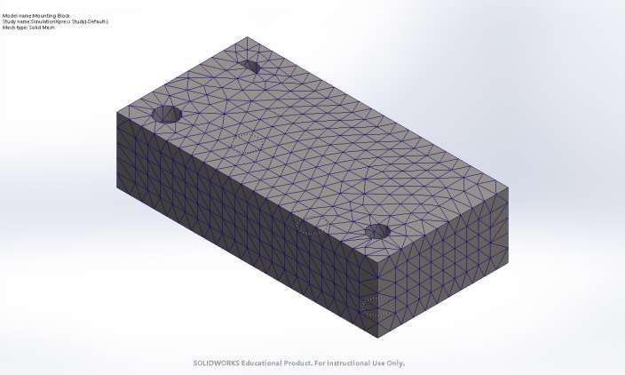
56
57 Study Results Name Type Min Max Stress VON: von Mises Stress N/m^2 Node: e+006 N/m^2 Node: Mounting Block-SimulationXpress Study-Stress-Stress Name Type Min Max Displacement URES: Resultant Displacement 0 mm Node: mm Node: 11573
58 Mounting Block-SimulationXpress Study-Displacement-Displacement Name Deformation Type Deformed shape
59 Mounting Block-SimulationXpress Study-Displacement-Deformation Name Type Min Max Factor of Safety Max von Mises Stress Node: Node: 9487
60 Mounting Block-SimulationXpress Study-Factor of Safety-Factor of Safety Conclusion The minimum FoS that occurs during the maximum loading of this block is 79. A-17
61 A-9

62 A-10
63 A-11
64 A-12
65 A-14
66 A-15
67 A-16
68 A-17
69 A-18
70 A-19
71 A-20
72 A-21
73 A-22
74 A-23
75 A-24
76 A-25
77 A-26
78 A-27
79 A-28
80 A-29
81 A-30
82 A-31
83 A-32
84 A-33
85 A-34
86 A-35

87 A-36
88 A-37
89 A-38
90 A-39-1
91 A-39-2

92 A-40
93 A-41
94 A-42
95 A-43
96 A-44
97 A-45
98 A-46

99 Appendix B B-1

100 B-2

101 B-3
102 B-4
103 B-5
104 B-6

105 B-7
106 B-8
107 B-9
108 B-10 (OLD CONCEPT)
109 B-11 (OLD CONCEPT)
110 B-12 (OLD CONCEPT)
111 B-13 (OLD CONCEPT)
112 B-14 (OLD CONCEPT)
113 B-15
114 B-16
115 B-17 (OLD CONCEPT)
116 B-18
117 B-19
118 B-20
119 Appendix C: Item Desc Supplier Part # Quantity Gas Spring Bansbach A3A3Z N. 1 Shoulder Bolt Fastenal Grade 8 ½ x 2 Bolt Fastenal E-clips Fastenal Machine Screw Fastenal Al Rod Metals Depot R318 6ft Clevis Pin Fastenal Cotter Pin Fastenal /8 Nylon Spacer Fastenal Grade 8 ¼ -20 x 3 Bolt Fastenal /2 Stop Bolt Fastenal ¼ Washer Fastenal
120 ¼ Nut Fastenal /8 Washer Fastenal /8 Nut Fastenal /8 Jam Nut Fastenal 1 3/8 Washer Fastenal ½ Washer Fastenal for Arm Speedy Metals 18f.25x for Mount Block Speedy Metals 18f2x3-6 6 (custom) 6061 round for Shelf Bars Online Metals NO PART # 6ft 6061 for Shelf Wall Online Metals NO PART # 1/8 x 24 x for Shelves Online Metals NO PART # ¼ x 12 x 36 Appendix D: Current Budget: Item Desc Supplier Part # Cost Quantity
121 Clevis Pin Fastenal DONATION 1 Cotter Pin Fastenal DONATION 1 Gas Spring Bansbach A3A3Z N. $18 1 Shoulder Bolt Fastenal DONATION 1 Grade 8 ½ x 2 Bolt Fastenal DONATION 1 E-clips Fastenal DONATION 8 Machine Screw Fastenal DONATION 8 Al Rod Metals Depot R318 $3.70 6ft 1/8 Nylon Spacer Fastenal DONATION 5 Grade 8 ¼ -20 x 3 Bolt Fastenal DONATION 1 1/2 Stop Bolt Fastenal DONATION 1 ¼ Washer Fastenal DONATION 1
122 ¼ Nut Fastenal DONATION 1 5/8 Washer DONATION 1 5/8 Nut DONATION 1 3/8 Jam Nut DONATION 1 3/8 Washer DONATION 2 ½ Washer DONATION for Arm Speedy Metals 18f.25x $ for Mount Block Speedy Metals 18f2x3-6 $ (custom) 6061 round for Shelf Bars Online Metals NO PART # $1.21 6ft 6061 for Shelf Wall Online Metals NO PART # $ /8 x 24 x for Shelves Online Metals NO PART # $38.25 ¼ x 12 x 36 Housing Wood Home Depot NO PART # $ board feet ¾ tubing Speedymetals NO PART # $ Steel brackets ACE HARDWARE NO PART # $5.64 4
123 5/16 x 3 bolt ACE HARDWARE NO PART # $3.54 X TOTAL $ **Red text indicates stock that would be bought if the aluminum shelving concepts were going to be manufactured** Appendix E: SCHEDULE FOR SENIOR PROJECT PROJECT TITLE: High Accessibility Kitchen Cabinet Insert WINTER
124

125 SPRING

126
127 Appendix H Testing report and Data Matthew Leal Test Design Guide Introduction: The testing required to determine whether or not the current design is a success will be compared to the requirements seen below
128 Requirements o Must hold a nominal weight of 15#, and a max weight of 30# o Must lower highest shelf between to bottom of cabinet space. o Must fit into a standard 27 x 16 x 11 cabinet space o Entire unit must weigh less than 30# without load o Must have a safety factor at least 1.5 on strengths of linkage arms o Must assist user needed force to raise nominal load by at least 50% TEST 1 The first test that will be conducted will compare the predicted user force input necessary to raise and lower the shelf with the nominal loading. The predicted forces involved in the operation of this device are 3.48lbf to lower the shelf, and 2.85lb to raise the shelf. These forces are indicative of the forces used to overwhelm the moment caused by the gas spring, so this force will cause the moment to become zero. Due to this, in order to generate movement, the forces involved will be very slightly higher than the predicted values dependant on how fast the user moves the shelf. Data will be acquired with a spring scale, which will be attached to both the shelf and the user s hand, and will measure the force generated by the user. Method/Approach: (describe in detail) Resources (hard/soft/external, people, costs), The procedure and resources necessary for this test will be very simple and straightforward. A spring scale will be needed in order to capture the data. Four 5lb weights will simulate the optimal loading scenario for the shelf. The shelf s housing must be mounted to a table for the shelf not to flip over, but in this case, an assistant will simply hold the shelf in place, to prevent tipping. The procedure will cost nothing, as CWU MET has all the materials necessary. data capture/doc/processing Data will be captured in the table below.
129 TOP LOADED TOP LOADED TOP LOADED TOP LOADED TOP LOADED TOP LOADED TOP LOADED TOP LOADED TOP LOADED BOTTOM LOADED BOTTOM LOADED BOTTOM LOADED BOTTOM LOADED BOTTOM LOADED BOTTOM LOADED BOTTOM LOADED BOTTOM LOADED HALF/HALF HALF/HALF HALF/HALF HALF/HALF HALF/HALF HALF/HALF TRIAL WEIGHT (lb) F_UP (lbf) F_DOWN (lbf) WEIGHT F_UP AVG (lbf) F_DOWN AVG (lbf)
130 Test procedure overview The user will place both ten pound weights into the shelf, and proceed to pull the shelf down, and record the data. The user will repeat the same thing for pushing the shelf up into its start position. precision and accuracy discussion The force will be ever changing as the user operates the device. A highest and lowest force will be acquired, and the average force will be calculated. data presentation The average forces for each trial will be presented in a simple table/graph, comparing the results to the predicted values. Test Procedure: (formal procedure) Summary/overview The user will place both ten pound weights into the shelf, and proceed to pull the shelf down, and record the data. The user will repeat the same thing for pushing the shelf up into its start position. Specify time, duration There are three trails involved in the testing of this requirement. This will take an estimated minutes total to test the device, and collect the data. resources needed This test will require the following A surface to mount the housing to. A spring scale measuring to the nearest lb. Four five-pound weights
131 A protractor Specific actions to complete the test, 18. Fasten/Hold down the housing to prevent movement during testing. This can be done by clamping down the mounted brackets on the back to at table. Use 2 C-clamps to do this. 19. Attach the 5lb weight to the spring scale and note any discrepancy in the spring scales weight readout. 20. Attach the spring scale to the handle on the shelf 21. With the shelf unloaded and in the upright position, pull the spring scale to initiate movement of the shelf, ensuring the user force is 60 degrees down from the plane parallel to the surface you have clamped the housing to. 22. Once the shelf has been lowered all the way, record the max spring scale value shown on the spring scale. 23. Return the shelf to its upright position. 24. Next, begin the top-loaded trial. Load 5lbs weight to the center of the top shelf. 25. In a similar manner to step 3, pull the spring scale to initiate movement of the shelf, ensuring the user force is 60 degrees down from the plane parallel to the surface you have clamped the housing to. 26. Once the shelf has been lowered all the way, record the max spring scale value shown on the spring scale. 27. Zero the spring scale 28. In a natural manner, i.e. pushing the shelf up as you would in a real scenario, use the spring scale to pull the shelf back into its original position. Record the max spring scale value shown on the spring scale. 29. Repeat steps 6-11 with a 10-pound and a 20-pound loading on the shelf. Ensure the weights are evenly distributed along the surface of the top shelf. 30. Repeat steps 6-11 one more time for a second trial, 31. Begin the bottom-loaded trial. Repeat steps 6-13, but load the weight onto the bottom shelf. 32. Begin the half/half trial. Repeat steps 6-13, but load the weight equally between the two shelves. i.e. for the 10-pound trial, put one 5lb on the top shelf, and one 5lb on the bottom shelf. *note, skip the 5lb trial for half/half* 33. Remove the gas spring from the device. 34. Using the half/half loading strategy outlined in step 15, repeat steps 6-13 without the spring attached. *WARNING* Without the spring, the shelf should descend very quickly.
132 risk, safety, evaluation readiness, other? This is a safe test, and since it s at the optimal weight, and not the designed safety max, it should be fine. However, ensuring the shelf is properly mounted to the test surface is crucial. Deliverables: Keeping the housing mounted proved to be difficult with the higher weight tests. A new mounting design should be accomplished before the next test. Averaging all loading scenarios, without load, the user must exert a force of 0lbf raising the shelf (gas spring has enough power to raise the unloaded shelf), and 8lbf lowering the shelf. At the nominal max load, the user must exert 12.7lbf to raise the shelf, and 14.4lbf to lower it. This is much higher than originally predicted, possibly due to the amount of friction and interference the shelf has in all its moving parts. With only one arm, this problem is huge. The implementation of a second arm should help clear this up slightly. As can be seen in the User Force V Load diagram in the report appendix, at higher loadings, the discrepancy between predicted and measured forces increases dramatically. This is undoubtedly caused by the difficulty in raising and lowering the shelf due to the torsion that is put on the link arm. Overall, the measured forces up were much higher than predicted, and the measured forces down were much lower, both by about a factor of two. There could be a major error in prediction analysis. In order to bring forces to a much more manageable place, a stronger gas spring could be implemented. However, after testing with a 40lbf spring as opposed to the current 30lbf, it has been deemed to dangerous. While an unloaded shelf is locked into place, the 40lbf spring is so powerful that it would snap the whole shelf upward in a violent fashion. Report Appendix:
133 Force (lbf) User Force (lbf) User Force V Load Measured Force Up Predicted Force Up Measured Force Down Predicted Force Down Load (lbs) Predicted Vs Measured Forces (UP) Predicted Up Actual Up Force Load (lbs)
134 Force (lbf) Measured Force V No Spring Force (UP) Load (lbs) Measured Up No Spring Up TOP LOADED TRIAL WEIGHT (lb) F_UP (lbf) F_DOWN (lbf) TOP LOADED TOP LOADED TOP LOADED TOP LOADED TOP LOADED TOP LOADED TOP LOADED TOP LOADED BOTTOM LOADED BOTTOM LOADED BOTTOM LOADED BOTTOM LOADED BOTTOM LOADED
135 BOTTOM LOADED BOTTOM LOADED BOTTOM LOADED HALF/HALF HALF/HALF HALF/HALF HALF/HALF HALF/HALF HALF/HALF WEIGHT F_UP AVG (lbf) F_DOWN AVG (lbf) Measured WEIGHT F_UP AVG (lbf) F_DOWN AVG (lbf) No Spring WEIGHT F_UP AVG (lbf) F_DOWN AVG (lbf) Predicted PROCEDURE CHECKLIST 1. Fasten/Hold down the housing to prevent movement during testing. This can be done by clamping down the mounted brackets on the back to at table. Use 2 C-clamps to do this. 2. Attach the 5lb weight to the spring scale and note any discrepancy in the spring scales weight readout. 3. Attach the spring scale to the handle on the shelf
136 4. With the shelf unloaded and in the upright position, pull the spring scale to initiate movement of the shelf, ensuring the user force is 60 degrees down from the plane parallel to the surface you have clamped the housing to. 5. Once the shelf has been lowered all the way, record the max spring scale value shown on the spring scale. 6. Return the shelf to its upright position. 7. Next, begin the top-loaded trial. Load 5lbs weight to the center of the top shelf. 8. In a similar manner to step 3, pull the spring scale to initiate movement of the shelf, ensuring the user force is 60 degrees down from the plane parallel to the surface you have clamped the housing to. 9. Once the shelf has been lowered all the way, record the max spring scale value shown on the spring scale. 10. Zero the spring scale 11. In a natural manner, i.e. pushing the shelf up as you would in a real scenario, use the spring scale to pull the shelf back into its original position. Record the max spring scale value shown on the spring scale. 12. Repeat steps 6-11 with a 10-pound and a 20-pound loading on the shelf. Ensure the weights are evenly distributed along the surface of the top shelf. 13. Repeat steps 6-11 one more time for a second trial, 14. Begin the bottom-loaded trial. Repeat steps 6-13, but load the weight onto the bottom shelf. 15. Begin the half/half trial. Repeat steps 6-13, but load the weight equally between the two shelves. i.e. for the 10-pound trial, put one 5lb on the top shelf, and one 5lb on the bottom shelf. *note, skip the 5lb trial for half/half* 16. Remove the gas spring from the device. 17. Using the half/half loading strategy outlined in step 15, repeat steps 6-13 without the spring attached. *WARNING* Without the spring, the shelf should descend very quickly. TIMELINE
137
138 TEST 2 At the time of the second test, a second link arm was to have been installed. However, due to shipping error, the part did not arrive in time. So, the second test consisted of a deflection test of the original link arm. The link arm will be loaded to its max weight, a simple material yield check will be performed, and a deflection measurement will be taken. Method/Approach: (describe in detail) Resources (hard/soft/external, people, costs), The procedure and resources necessary for this test will be very simple and straightforward. A dial indicator mic will be necessary to measure the deflection, along with 60lbs of weight. As the mount block will be removed from the housing, clamps will be necessary to mount the block to a work surface. In general, this test would best be replicated in a lab/shop environment. data capture/doc/processing Data will be captured in the table below. TRIAL LOAD (lbs) DEFLECTION (in)

139 1 2 3 PREDICTED Test procedure overview The user will place 60lbs of weight on the tip of the link arm, on top of the hole where the shelf would normally be mounted. The user will then measure deflection of the tip with the dial indicator. precision and accuracy discussion The dial indicator involved MUST read to the nearest To ensure accuracy, there will be three trials. The deflection must be measured to the nearest The average deflection will be compared to the predicted deflection in an excel type chart. C clamps
Stationary Bike Generator System (Drive Train)
") Central Washington University ScholarWorks@CWU All Undergraduate Projects Undergraduate Student Projects Summer 2017 Stationary Bike Generator System (Drive Train) Abdullah Adel Alsuhaim cwu, 280zxf150@gmail.com
Central Washington University ScholarWorks@CWU All Undergraduate Projects Undergraduate Student Projects Summer 2017 Stationary Bike Generator System (Drive Train) Abdullah Adel Alsuhaim cwu, 280zxf150@gmail.com
Pin Router Duplicator Base
 Central Washington University ScholarWorks@CWU All Undergraduate Projects Undergraduate Student Projects Spring 2017 Pin Router Duplicator Base Matthew Tebo tebom@cwu.edu Follow this and additional works
Stationary Bike Generator System
 Central Washington University ScholarWorks@CWU All Undergraduate Projects Undergraduate Student Projects Spring 2017 Stationary Bike Generator System Rakan Alghamdi Central Washington University, rk_rk11@hotmail.com
Introduction: Problem statement
 Introduction: Problem statement The goal of this project is to develop a catapult system that can be used to throw a squash ball the farthest distance and to be able to have some degree of accuracy with
Technical Math 2 Lab 3: Garage Door Spring 2018
 Name: Name: Name: Name: As you may have determined the problem is a broken spring (clearly shown on the left in the picture below) which needs to be replaced. I. Garage Door Basics: Common residential
PVP Field Calibration and Accuracy of Torque Wrenches. Proceedings of ASME PVP ASME Pressure Vessel and Piping Conference PVP2011-
 Proceedings of ASME PVP2011 2011 ASME Pressure Vessel and Piping Conference Proceedings of the ASME 2011 Pressure Vessels July 17-21, & Piping 2011, Division Baltimore, Conference Maryland PVP2011 July
ASME Human Powered Vehicle
 ASME Human Powered Vehicle By Yousef Alanzi, Evan Bunce, Cody Chenoweth, Haley Flenner, Brent Ives, and Connor Newcomer Team 14 Mid-Point Review Document Submitted towards partial fulfillment of the requirements
SAE Mini BAJA: Suspension and Steering
 SAE Mini BAJA: Suspension and Steering By Zane Cross, Kyle Egan, Nick Garry, Trevor Hochhaus Team 11 Progress Report Submitted towards partial fulfillment of the requirements for Mechanical Engineering
PYRTE. Building The Front Axle, Fork and Steering
 PYRTE Building The Front Axle, Fork and Steering The front axle on this traction engine is a very simple affair, in that it is a rectangular steel rod, sat on edge, with a pivot in the centre, which is
Chapter 11. Keys, Couplings and Seals. Keys. Parallel Keys
 Chapter 11 Keys, Couplings and Seals Material taken for Keys A key is a machinery component that provides a torque transmitting link between two power-transmitting elements. The most common types of keys
Hydraulic Sprayer Boom Upgrade
 Central Washington University ScholarWorks@CWU All Undergraduate Projects Undergraduate Student Projects Spring 2016 Hydraulic Sprayer Boom Upgrade Chad R. Omlin Central Washington University, chadomlin@gmail.com
USE AN ENGINEERED APPROACH TO TAILOR A PERFECT STANDARD GAS SPRING FOR YOUR DESIGN A GUIDE TO GAS SPRING DESIGN AND CUSTOMIZATION WH ITE PA P E R
 WH ITE PA P E R USE AN ENGINEERED APPROACH TO TAILOR A PERFECT STANDARD GAS SPRING FOR YOUR DESIGN A GUIDE TO GAS SPRING DESIGN AND CUSTOMIZATION When your machine design calls for an industrial gas spring,
Using ABAQUS in tire development process
 Using ABAQUS in tire development process Jani K. Ojala Nokian Tyres plc., R&D/Tire Construction Abstract: Development of a new product is relatively challenging task, especially in tire business area.
External Hard Drive: A DFMA Redesign
 University of New Mexico External Hard Drive: A DFMA Redesign ME586: Design for Manufacturability Solomon Ezeiruaku 4-23-2013 1 EXECUTIVE SUMMARY The following document serves to illustrate the effects
NEW CAR TIPS. Teaching Guidelines
 NEW CAR TIPS Teaching Guidelines Subject: Algebra Topics: Patterns and Functions Grades: 7-12 Concepts: Independent and dependent variables Slope Direct variation (optional) Knowledge and Skills: Can relate
Metal forming machines: a new market for laser interferometers O. Beltrami STANIMUC Ente Federate UNI, via A. Vespucci 8, Tbrmo,
 Metal forming machines: a new market for laser interferometers O. Beltrami STANIMUC Ente Federate UNI, via A. Vespucci 8, Tbrmo, Abstract Laser interferometers have traditionally been a synonymous of very
SAE Mini BAJA: Suspension and Steering
 SAE Mini BAJA: Suspension and Steering By Zane Cross, Kyle Egan, Nick Garry, Trevor Hochhaus Team 11 Project Progress Submitted towards partial fulfillment of the requirements for Mechanical Engineering
Assemblies for Parallel Kinematics. Frank Dürschmied. INA reprint from Werkstatt und Betrieb Vol. No. 5, May 1999 Carl Hanser Verlag, München
 Assemblies for Parallel Kinematics Frank Dürschmied INA reprint from Werkstatt und Betrieb Vol. No. 5, May 1999 Carl Hanser Verlag, München Assemblies for Parallel Kinematics Frank Dürschmied Joints and
Progress Report. Maseeh College of Engineering & Computer Science Winter Kart 2. Design Team Atom Falcone Austin Greene. Nick Vanklompenberg
 Progress Report Maseeh College of Engineering & Computer Science Winter 2016 Kart 2 Design Team Atom Falcone Austin Greene Jesse Majoros Nick Vanklompenberg Jake Waterman Jeffrey Williamson Faculty Advisor
MODELING SUSPENSION DAMPER MODULES USING LS-DYNA
 MODELING SUSPENSION DAMPER MODULES USING LS-DYNA Jason J. Tao Delphi Automotive Systems Energy & Chassis Systems Division 435 Cincinnati Street Dayton, OH 4548 Telephone: (937) 455-6298 E-mail: Jason.J.Tao@Delphiauto.com
Remote Control Helicopter. Engineering Analysis Document
 Remote Control Helicopter By Abdul Aldulaimi, Travis Cole, David Cosio, Matt Finch, Jacob Ruechel, Randy Van Dusen Team 04 Engineering Analysis Document Submitted towards partial fulfillment of the requirements
LEAD SCREWS 101 A BASIC GUIDE TO IMPLEMENTING A LEAD SCREW ASSEMBLY FOR ANY DESIGN
 LEAD SCREWS 101 A BASIC GUIDE TO IMPLEMENTING A LEAD SCREW ASSEMBLY FOR ANY DESIGN Released by: Keith Knight Kerk Products Division Haydon Kerk Motion Solutions Lead Screws 101: A Basic Guide to Implementing
ECSE-2100 Fields and Waves I Spring Project 1 Beakman s Motor
 Names _ and _ Project 1 Beakman s Motor For this project, students should work in groups of two. It is permitted for groups to collaborate, but each group of two must submit a report and build the motor
DESIGN OF AUTOMOBILE S BODY SHAPE AND STUDY ON EFFECT OF AERODYNAMIC AIDS USING CFD ANALYSIS
 DESIGN OF AUTOMOBILE S BODY SHAPE AND STUDY ON EFFECT OF AERODYNAMIC AIDS USING CFD ANALYSIS Akshay S 1, Ashik Vincent 2, Athul Anand R 3, George Kurian 4, Dr. Shajan Kuriakose 5 1,2,3,4 B-Tech Degree
TRANSLATION (OR LINEAR)
") 5) Load Bearing Mechanisms Load bearing mechanisms are the structural backbone of any linear / rotary motion system, and are a critical consideration. This section will introduce most of the more common
5) Load Bearing Mechanisms Load bearing mechanisms are the structural backbone of any linear / rotary motion system, and are a critical consideration. This section will introduce most of the more common
SAE Baja - Drivetrain
 SAE Baja - Drivetrain By Ricardo Inzunza, Brandon Janca, Ryan Worden Team 11A Concept Generation and Selection Document Submitted towards partial fulfillment of the requirements for Mechanical Engineering
USING INSPIRE AS AN UPFRONT DESIGN, OPTIMIZATION & SIMULATION TOOL FOR EXISITNG MANUAL GEARBOX COMPONENTS
 USING INSPIRE AS AN UPFRONT DESIGN, OPTIMIZATION & SIMULATION TOOL FOR EXISITNG MANUAL GEARBOX COMPONENTS Lokesh Kumar Gupta Manager Drive Line Eicher Polaris Plot- SP1 & 2, Kukas Jaipur India 302028 Lkgupta@eicherpolaris.in
Engineering Fundamentals Final Project Engineering Lab Report
 Engineering Fundamentals Final Project Engineering Lab Report 4/26/09 Tony Carr Christopher Goggans Zach Maxey Matt Rhule Team Section A2-6 Engineering Fundamentals 151 I have read and approved of the
Transmission Error in Screw Compressor Rotors
 Purdue University Purdue e-pubs International Compressor Engineering Conference School of Mechanical Engineering 2008 Transmission Error in Screw Compressor Rotors Jack Sauls Trane Follow this and additional
Design, Construction and Testing of an Electric Powered Toggle Jack Mechanism
 Design, Construction and Testing of an Electric Powered Toggle Jack Mechanism Ipilakyaa T.D. 1, Achirgbenda V.T. 2, Gbashi S. 3 1Department of Mechanical Engineering, University of Agriculture Makurdi,
MET 314 Torque Measurement
 Central Washington University ScholarWorks@CWU All Undergraduate Projects Undergraduate Student Projects Spring 2016 MET 314 Torque Measurement Jose Bejar Central Washington University, bejarj@cwu.edu
Orbital Test Stand. By Mary Begay, Brett Booen, Calvin Boothe, James Ellis and Nicholas Garcia. Team 7. Project Proposal Document
 Orbital Test Stand By Mary Begay, Brett Booen, Calvin Boothe, James Ellis and Nicholas Garcia Team 7 Project Proposal Document Submitted towards partial fulfillment of the requirements for Mechanical Engineering
Pearls from Martin J. King Quarter Wave Design
 Pearls from Martin J. King Quarter Wave Design An introduction by Bjorn Johannesen, Denmark. September the 1 st 2005. The first time you visit http://www.quarter-wave.com/, you might get overwhelmed by
Dynamics of Machines. Prof. Amitabha Ghosh. Department of Mechanical Engineering. Indian Institute of Technology, Kanpur. Module No.
 Dynamics of Machines Prof. Amitabha Ghosh Department of Mechanical Engineering Indian Institute of Technology, Kanpur Module No. # 04 Lecture No. # 03 In-Line Engine Balancing In the last session, you
Cassette Lockring Removal Tool
 Central Washington University ScholarWorks@CWU All Undergraduate Projects Undergraduate Student Projects Spring 2018 Cassette Lockring Removal Tool Kyle Wright Central Washington University, kylegwright@comcast.net
SHAFT ALIGNMENT FORWARD
 Service Application Manual SAM Chapter 630-76 Section 24 SHAFT ALIGNMENT FORWARD One of the basic problems of any installation is aligning couplings or shafts. Therefore, this section will endeavor to
Design Modification and Optimization of Trolley in an Off-Bearer Mechanism Present In Concrete Block Making Machines
 Design Modification and Optimization of Trolley in an Off-Bearer Mechanism Present In Concrete Block Making Machines Aravindhan. V 1, Anantha Krishnan. P 2 1,2Final Year UG Students, Dept. of Mechanical
Sequoia power steering rack service Match-mounting wheels and tires Oxygen sensor circuit diagnosis
 In this issue: Sequoia power steering rack service Match-mounting wheels and tires Oxygen sensor circuit diagnosis PHASE MATCHING Often referred to as match mounting, phase matching involves mounting the
PIONEER RESEARCH & DEVELOPMENT GROUP
 Design and Stress Analysis of Tow Bar for Medium Sized Portable Compressors Pankaj Khannade 1, Akash Chitnis 2, Gangadhar Jagdale 3 1,2 Mechanical Department, University of Pune/ Smt. Kashibai Navale College
Fisher 657 Diaphragm Actuator Sizes and 87
 Instruction Manual 657 Actuator (30-70 and 87) Fisher 657 Diaphragm Actuator Sizes 30 70 and 87 Contents Introduction... 1 Scope of Manual... 1 Description... 2 Specifications... 2 Installation... 3 Mounting
M:2:I Milestone 2 Final Installation and Ground Test
 Iowa State University AerE 294X/AerE 494X Make to Innovate M:2:I Milestone 2 Final Installation and Ground Test Author(s): Angie Burke Christopher McGrory Mitchell Skatter Kathryn Spierings Ryan Story
Is it Magnetic? 1. Fill in each table. List things ATTRACTED by a magnet on the LEFT and things NOT ATTRACTED on the RIGHT.
 Is it Magnetic? 1. Fill in each table. List things ATTRACTED by a magnet on the LEFT and things NOT ATTRACTED on the RIGHT. MAGNETIC NON-MAGNETIC # Object Made from check # Object Made from check --- ------------
Theory of Machines II EngM323 Laboratory User's manual Version I
 Theory of Machines II EngM323 Laboratory User's manual Version I Table of Contents Experiment /Test No.(1)... 2 Experiment /Test No.(2)... 6 Experiment /Test No.(3)... 12 EngM323 Theory of Machines II
Chapter 7: DC Motors and Transmissions. 7.1: Basic Definitions and Concepts
 Chapter 7: DC Motors and Transmissions Electric motors are one of the most common types of actuators found in robotics. Using them effectively will allow your robot to take action based on the direction
FOLDING SHOPPING CART
 1 EDSGN 100: Introduction to Engineering Design Section 10 Team 6 FOLDING SHOPPING CART Submitted by: Kevin Chacha, Ugonna Onyeukwu, Patrick Thornton, Brian Hughes Submitted to: Xinli Wu October 28, 2013
Safety factor and fatigue life effective design measures
 Safety factor and fatigue life effective design measures Many catastrophic failures have resulted from underestimation of design safety and/or fatigue of structures. Failure examples of engineered structures
Applications in Design & Engine. Analyzing Compound, Robotic Machines
 v2.1 Compound Machines ering Applications in Design & Engine Analyzing Compound, Robotic Machines Educational Objectives At the conclusion of this lesson, students should be able to: Understand the relationship
Abstract. Executive Summary. Emily Rogers Jean Wang ORF 467 Final Report-Middlesex County
 Emily Rogers Jean Wang ORF 467 Final Report-Middlesex County Abstract The purpose of this investigation is to model the demand for an ataxi system in Middlesex County. Given transportation statistics for
A Grinding Solution. By John Donkers
 A Grinding Solution A customer had a problem using their existing gears in a new application. Ontario Drive & Gear provided the solution. Here s how they did it. By John Donkers A company approached Ontario
Test-bed for Bose Speaker Impact Stress Analysis
 Test-bed for Bose Speaker Impact Stress Analysis Design Team Deema AlHasan, Rafael Hernandez Lourdes Sanfeliu, Ahmad Zameli Design Advisor Prof. Sagar Kamarthi Sponsor Harry Malkasian Abstract Bose, an
F.I.R.S.T. Robotic Drive Base
 F.I.R.S.T. Robotic Drive Base Design Team Shane Lentini, Jose Orozco, Henry Sick, Rich Phelan Design Advisor Prof. Sinan Muftu Abstract F.I.R.S.T. is an organization dedicated to inspiring and teaching
Central Braking Castors
 Central Braking Castors Congratulations for choosing Australia's famous Fallshaw castors Version 3 These instructions are in 4 sections... 1/ Configuration Preferred combinations of castor layout. 2/ Requirements
Bimotion Advanced Port & Pipe Case study A step by step guide about how to calculate a 2-stroke engine.
 Bimotion Advanced Port & Pipe Case study A step by step guide about how to calculate a 2-stroke engine. 2009/aug/21. Bimotion. This paper is free for distribution and may be revised, for further references
Sheet 1 Variable loading
 Sheet 1 Variable loading 1. Estimate S e for the following materials: a. AISI 1020 CD steel. b. AISI 1080 HR steel. c. 2024 T3 aluminum. d. AISI 4340 steel heat-treated to a tensile strength of 1700 MPa.
Semi-Active Suspension for an Automobile
 Semi-Active Suspension for an Automobile Pavan Kumar.G 1 Mechanical Engineering PESIT Bangalore, India M. Sambasiva Rao 2 Mechanical Engineering PESIT Bangalore, India Abstract Handling characteristics
PRESEASON CHASSIS SETUP TIPS
 PRESEASON CHASSIS SETUP TIPS A Setup To-Do List to Get You Started By Bob Bolles, Circle Track Magazine When we recently set up our Project Modified for our first race, we followed a simple list of to-do
Introduction. Kinematics and Dynamics of Machines. Involute profile. 7. Gears
 Introduction The kinematic function of gears is to transfer rotational motion from one shaft to another Kinematics and Dynamics of Machines 7. Gears Since these shafts may be parallel, perpendicular, or
Analysis of Eclipse Drive Train for Wind Turbine Transmission System
 ISSN 2395-1621 Analysis of Eclipse Drive Train for Wind Turbine Transmission System #1 P.A. Katre, #2 S.G. Ganiger 1 pankaj12345katre@gmail.com 2 somu.ganiger@gmail.com #1 Department of Mechanical Engineering,
EDSGN 100: INTRODUCTION TO ENGINEERING DESIGN Section 204 Team #1 BOX CART
 EDSGN 100: INTRODUCTION TO ENGINEERING DESIGN Section 204 Team #1 BOX CART Submitted by: Chang - http://www.personal.psu.edu/cbl5289/ Vinay Murthy - http://www.personal.psu.edu/vum119/ Aidan Fitzpatrick
Pre-lab Questions: Please review chapters 19 and 20 of your textbook
 Introduction Magnetism and electricity are closely related. Moving charges make magnetic fields. Wires carrying electrical current in a part of space where there is a magnetic field experience a force.
Clutch Installation Guide
 Clutch Installation Guide 0 STOP! READ CAREFULLY BEFORE INSTALLING CLUTCH This clutch must be installed by a qualified installer. Improper installation or failure to replace or resurface the flywheel,
Steer-by-Wire Systems with Integrated Torque Feedback Improve Steering Performance and Reduce Cost
 Steer-by-Wire Systems with Integrated Torque Feedback Improve Steering Performance and Reduce Cost Geoff Rondeau, Product Manager Thomson Industries, Inc. Wood Dale, IL 540-633-3549 www.thomsonlinear.com
Operator s Manual. Single Hand Manual Drive Wheelchair
 Operator s Manual Single Hand Manual Drive Wheelchair Jordan R. Smith Kayla Gosse Leah McElhaney Team #5 Project for Client: Danielle Giroux Client Contact Information: Dave and Suzanne Giroux 53 Charlotte
Troubleshooting Guide for Limoss Systems
 Troubleshooting Guide for Limoss Systems NOTE: Limoss is a manufacturer and importer of linear actuators (motors) hand controls, power supplies, and cables for motion furniture. They are quickly becoming
RELEASING PRESSURE IN THE HYDRAULIC SYSTEM,
 Testing And Adjusting Introduction NOTE: For Specifications with illustrations, make reference to SPECIFICATIONS for 225 EXCAVATOR HYDRAULIC SYSTEM, Form No. SENR7734. If the Specifications are not the
CHAPTER 6 GEARS CHAPTER LEARNING OBJECTIVES
 CHAPTER 6 GEARS CHAPTER LEARNING OBJECTIVES Upon completion of this chapter, you should be able to do the following: Compare the types of gears and their advantages. Did you ever take a clock apart to
INME 4011 Term Project Guideline
 INME 4011 Term Project Guideline Each team consists of four students (maximum). The projects are described in the attached document. First part of the project includes the calculation of the shaft diameter
Application of DSS to Evaluate Performance of Work Equipment of Wheel Loader with Parallel Linkage
 Technical Papers Toru Shiina Hirotaka Takahashi The wheel loader with parallel linkage has one remarkable advantage. Namely, it offers a high degree of parallelism to its front attachment. Loaders of this
Cane Creek Double Barrel Instructions
 Cane Creek Double Barrel Instructions Congratulations on your purchase of the Cane Creek Double Barrel rear shock. Developed in partnership with Öhlins Racing, the Double Barrel brings revolutionary suspension
SAE Baja - Drivetrain
 SAE Baja - Drivetrain By Ricardo Inzunza, Brandon Janca, Ryan Worden Team 11 Engineering Analysis Document Submitted towards partial fulfillment of the requirements for Mechanical Engineering Design I
Simple Gears and Transmission
 Simple Gears and Transmission Simple Gears and Transmission page: of 4 How can transmissions be designed so that they provide the force, speed and direction required and how efficient will the design be?
Bridge Overhang Brackets
 Bridge C49, C49D, C49S and C49JR Bridge Dayton Superior offers the bridge contractor four different Horizontal Length versions of the C49 Bridge Bracket, which allows for maximum adjustability to meet
The Deployable Gage Restraint Measurement System - Description and Operational Performance
 The Deployable Gage Restraint Measurement System - Description and Operational Performance GARY A. MARTIN ENSCO, INC 5400 PORT ROYAL ROAD SPRINGFIELD, VA 22151 703-321-4513 703-321-7619 (FAX) JEFFREY A.
Rocket Races. Rocket Activity. Objective Students investigate Newton s third law of motion by designing and constructing rocketpowered
 Rocket Activity Rocket Races Objective Students investigate Newton s third law of motion by designing and constructing rocketpowered racing cars. National Science Content Standards Unifying Concepts and
Increase Factor of Safety of Go-Kart Chassis during Front Impact Analysis
 IJIRST International Journal for Innovative Research in Science & Technology Volume 3 Issue 04 September 2016 ISSN (online): 2349-6010 Increase Factor of Safety of Go-Kart Chassis during Front Impact Analysis
Riverhawk Company 215 Clinton Road New Hartford NY (315) Free-Flex Flexural Pivot Engineering Data
 Free-Flex Flexural Pivot Engineering Data") Riverhawk Company 215 Clinton Road New Hartford NY (315)768-4937 Free-Flex Flexural Pivot Engineering Data PREFACE Patented Flexural Pivot A unique bearing concept for applications with limited angular
Riverhawk Company 215 Clinton Road New Hartford NY (315)768-4937 Free-Flex Flexural Pivot Engineering Data PREFACE Patented Flexural Pivot A unique bearing concept for applications with limited angular
Spark plugs and the Rotax Engine
 Spark plugs and the Rotax Engine Part 2 In part 1 of this article, we discussed the theoretical aspects of the spark plugs installed in the Rotax engines. In this article, we will take a more in-depth
Power Workholding. Power Workholding n Precision Vises n Zero Point Mounting n Assembly and Handling
 Power Workholding Power Workholding n Precision Vises n Zero Point Mounting n Assembly and Handling OUR STORY In 1982 an independent joint venture was established to marry the proven product expertise
Trust but verify: the value of acceptance testing
 Trust but verify: the value of acceptance testing Les Miller, Dave VanLangevelde and Rick Burgess, Kaydon Bearings For many applications, the values and engineering data in bearing manufacturers catalogs
SECTION G2: CABLE PROCESSOR MODULE MAINTENANCE
 SECTION G2: CABLE PROCESSOR MODULE MAINTENANCE Cable Processor Module overview WARNING! When tipping the Cable Processor Module back, (after removing the toggle arm pin), use extreme caution not to drop
Structural Analysis of Student Formula Race Car Chassis
 Structural Analysis of Student Formula Race Car Chassis Arindam Ghosh 1, Rishika Saha 2, Sourav Dhali 3, Adrija Das 4, Prasid Biswas 5, Alok Kumar Dubey 6 1Assistant Professor, Dept. of Mechanical Engineering,
TITLE: EVALUATING SHEAR FORCES ALONG HIGHWAY BRIDGES DUE TO TRUCKS, USING INFLUENCE LINES
 EGS 2310 Engineering Analysis Statics Mock Term Project Report TITLE: EVALUATING SHEAR FORCES ALONG HIGHWAY RIDGES DUE TO TRUCKS, USING INFLUENCE LINES y Kwabena Ofosu Introduction The impact of trucks
FUNCTION OF A BEARING
 Bearing FUNCTION OF A BEARING The main function of a rotating shaft is to transmit power from one end of the line to the other. It needs a good support to ensure stability and frictionless rotation. The
North Dakota State University Diesel Powered Clean Snowmobile
 Copywrite 2014 SAE International Abstract To be competitive in this year s Clean Snowmobile Challenge the NDSU team will be utilizing a 2011 Polaris Pro-R chassis and a diesel engine. The engine that will
Load Cell for Manually Operated Presses Model 8451
 w Technical Product Information Load Cell for Manually Operated Presses 1. Introduction... 2 2. Preparing for use... 2 2.1 Unpacking... 2 2.2 Using the instrument for the first time... 2 2.3 Grounding
Are you as confident and
 64 March 2007 BY BOB PATTENGALE Although Mode $06 is still a work in progress, it can be used to baseline a failure prior to repairs, then verify the accuracy of the diagnosis after repairs are completed.
Guide Wheel System Properties, Selection & Sizing
 Guide System Properties, Selection & Sizing Brett Frederick, Project Engineer, C.G. Bretting Manufacturing Kevin Kegel, AssemblySpecialist, C.G. Bretting Manufacturing Paper dust particulates wreak havoc
Spacing and Pattern Effects on DU LQ of Spray Nozzles
 Spacing and Pattern Effects on DU LQ of Spray Nozzles Introduction Brent Q. Mecham 1 September 11, 2006 One of the current Turf and Landscape Best Management Practices published by the Irrigation Association
Throttle Cable Pull - Patent Pending By: NetGain Controls, Inc.
 Throttle Cable Pull - Patent Pending By: NetGain Controls, Inc. Powering the future! Installation Guide 2011 All Rights Reserved NetGain Controls, Inc. 1 of 8 Introduction Thank you for purchasing a NetGain
25455/25470/ Toyota Adjustable Upper Control Arms
 Toyota Adjustable Upper Control Arms Q1: I have a lift kit; will the control arms handle the increased angle? A1: These control arms have approximately 20 more articulation capability than your OEM arms
Cam Motion Case Studies #1 and # 2
 Cam Motion Case Studies #1 and # 2 Problem/Opprtunity: At an operating speed of 150 to 160 rpm, Cam Motion #1 causes the cam follower to leave the cam surface unless excessive air pressure is applied to
Chapter 11 Rolling Contact Bearings
 Chapter 11 Rolling Contact Bearings 1 2 Chapter Outline Bearing Types Bearing Life Bearing Load Life at Rated Reliability Bearing Survival: Reliability versus Life Relating Load, Life, and Reliability
APPLICATION NOTES VALVE CHECKER M
 APPLICATION NOTES VALVE CHECKER M040-120-001 1 of 16 CONTENTS Chapter Title Page 1. Description 3 2. Specification 7 3. Connecting to valve and plant 8 4. Plant mode operation (in line) 9 5. Checker mode
NARCOA CUSTOM-BUILT & HIGHLY- MODIFIED MOTORCAR GUIDELINES
 NARCOA CUSTOM-BUILT & HIGHLY- MODIFIED MOTORCAR GUIDELINES VERSION 1.6 October 2006 INTRODUCTION and INTENT - This handbook was developed to create a set of guidelines that provides inspectors, excursion
Project Report Cover Page
 New York State Pollution Prevention Institute R&D Program 2015-2016 Student Competition Project Report Cover Page University/College Name Team Name Team Member Names SUNY Buffalo UB-Engineers for a Sustainable
TrueGyde Microcoil. Author: Marcel Berard Co-Author: Philippe Berard
 Author: Marcel Berard Co-Author: Philippe Berard Introduction TrueGyde Steer supports the microcoil as an alternate magnetic source to the standard coil. This document describes how to build and use a
Bicycles in Zambia: A study in two design approaches. Authors: Dan Janosec, Bala Radharamanan, Tony Ricciardi
 Bicycles in Zambia: A study in two design approaches Authors: Dan Janosec, Bala Radharamanan, Tony Ricciardi Design Brief As it currently stands, most farmers in Zambia utilize hand tools in order to complete
Smart Automated Vent Register Using an SMA Spring Actuated Rotary Ratchet
 Smart Automated Vent Register Using an SMA Spring Actuated Rotary Ratchet Mary Molepske, Victor Braciszewski, James Butler, Gregory Caputo, Fan-Ning Cheng, WonHee Kim, Jonathan Luntz, Diann Brei ABSTRACT
Mechanical Considerations for Servo Motor and Gearhead Sizing
 PDHonline Course M298 (3 PDH) Mechanical Considerations for Servo Motor and Gearhead Sizing Instructor: Chad A. Thompson, P.E. 2012 PDH Online PDH Center 5272 Meadow Estates Drive Fairfax, VA 22030-6658
HIGH VOLTAGE vs. LOW VOLTAGE: POTENTIAL IN MILITARY SYSTEMS
 2013 NDIA GROUND VEHICLE SYSTEMS ENGINEERING AND TECHNOLOGY SYMPOSIUM POWER AND MOBILITY (P&M) MINI-SYMPOSIUM AUGUST 21-22, 2013 TROY, MICHIGAN HIGH VOLTAGE vs. LOW VOLTAGE: POTENTIAL IN MILITARY SYSTEMS