MET 314 Torque Measurement
|
|
|
- April Smith
- 5 years ago
- Views:
Transcription
.")
1 Central Washington University All Undergraduate Projects Undergraduate Student Projects Spring 2016 MET 314 Torque Measurement Jose Bejar Central Washington University, Follow this and additional works at: Part of the Manufacturing Commons Recommended Citation Bejar, Jose, "MET 314 Torque Measurement" (2016). All Undergraduate Projects. Paper 25. This Undergraduate Project is brought to you for free and open access by the Undergraduate Student Projects at It has been accepted for inclusion in All Undergraduate Projects by an authorized administrator of
2 MET 314 Torque Measurement Lab By Jose Bejar
3 Table of Contents INTRODUCTION... 4 Motivation:... 4 Function Statement:... 4 Requirements:... 4 Engineering Merit:... 4 Scope of Effort:... 5 Success Criteria:... 5 Success of the Project:... 5 DESIGN & ANALYSIS... 6 Proposed Solution:... 6 Description:... 6 Benchmark:... 6 Performance Predictions:... 7 Description of Analyses:... 7 Scope of Testing and Evaluation:... 8 Analyses:... 8 Device: Parts, Shapes, and Conformation:... 8 Device Assembly and Attachments:... 8 Tolerances, Kinematics, Ergonomics:... 8 Technical Risk Analysis, Failure Mode Analysis, Safety Factors, Operation Limits:... 9 Methods and Construction: Description: Drawing Tree: Parts List and Labels: Manufacturing Issues: Assembly, Sub- assembly, Parts, Drawings: Testing Method Introduction: Method: Procedure: Deliverables: Budget/Schedule/Project Management Proposed Budget: Proposed Schedule: Project Management Conclusion Acknowledgements Appendix A: Analyses Appendix B: Drawings Figure 1: Bearing Housing Figure 3: Front Motor Plate
4 Figure 4: Rear Motor Plate Figure 5: Motor Platform Figure 6: Platform Lever Figure 7: Shaft Figure 8: Shaft Housing Figure 9: Load Cell Base Figure 10: Motor Platform Assembly APPENDIX C Parts List APPENDIX D Budget APPENDIX E Schedule APPENDIX H Testing Report Introduction: Method: Procedure: Deliverables: APPENDIX I Testing Data APPENDIX J Resume
5 INTRODUCTION Motivation: This project was motivated by the need of a device that would measure the torque on a motor from a thermodynamics lab setup in Hogue Hall. There are devices out there to measure the torque produced by motors, but they are too expensive. There are dynamometers for small engines such as the one used in the Power Tech Lab, but they are not small enough to be used on the air motor for the thermodynamics lab and even if they were they would be very expensive. This new measurement will allow the thermodynamics students to use the obtained torque value to take the calculations involved in the lab to another level. Function Statement: A device is needed that will suspend an air motor on bearings and allow it to swing from side to side while a lever attached to the motor or base where the motor sits which will presses down on a load cell that will be wired to a load cell indicator sensor meter that will display the value of the force from the motor on the cell. Requirements: This device must meet the following requirements: The device must fit within the existing lab setup. It must take up no more than 2ft 2 Total weight must be under 5lb in order to keep the lab setup lightweight in case it needs to be moved. Any part of the device must not rust. Must not affect the workability of the lab setup. Engineering Merit: In order to keep this device as lightweight and compact as possible while taking into consideration that the device must not rust overtime and maintain a nice clean finish there will be several calculations. The dimension of the torque arm will need to be calculated by first taking into account the maximum possible load that the motor will exert. The torque arm also has to be designed so that it deflects the least possible without increasing its dimensions too much. In order to keep the torque arm in a fixed position there will be bolts used and their diameter has to be calculated: F = T/(D bolts /2)), Shear stress in each bolt. N = number of bolts τ = F/As = F/(N(πd 2 /4)) = 2T/(D bc Nπd 2 /4) Required bolt diameter d = [(8T)/(D bc Nπτ)] 1/2 The diameter of the shafts also has to be calculated. Speeds and feeds have to be calculated for all the machining operations. 4
6 Scope of Effort: For this project the only things that will be made are the torque arm, and the base for the air motor. The load cell, digital display, and bearings will be purchased; the bolts will be obtained from the shop. Success Criteria: In order for this device to be considered successful it must meet the following criteria: The torque arm will not break when measuring the force on the load cell. The torque calculated will be within a reasonable range; if it comes out to 1000lb/in something obviously went wrong. The torque calculated will be within 10% of the manufacturer s specs. Simple to manufacture. Long design life. Success of the Project: The success of this project depends on whether or not the force read by the load cell display leads students to calculate a torque within 10% of the manufacturer s specifications. It will also be considered a successful project if on top of being within a reasonable range of torque values the device will continue to display those values for years without maintenance. Mainly, in order for this project to be considered successful will depend on if students are able to use the device after a simple explanation by the professor running the lab. 5
7 DESIGN & ANALYSIS Proposed Solution: Professor Beardsley provided insightful information to solve this problem. He mentioned that the motor could be placed on bearings and have some sort of lever on the shaft with a strain gauge. The solutions chosen for this problem includes some of those ideas. The air motor will be fixed to a platform that will have a shaft at one end that will sit on bearings so that the platform can rotate. There will be a torque arm attached to the platform where the motor will sit. This design will allow the outer casing of the motor to be free allowing the lever to push down on a load cell. Description: The design for this lab must ensure that it will not rust over time, it will have a nice clean finish, and it will also not add too much weight or take up too much space. Because of this requirements the best material to fit the device is an aluminum alloy since it is light weight, it has high tensile, compression, and shear properties along with the fact that it will not rust. There are two main functions this device will perform. The first function consists of the motor rotating about an axis concentric to the axis of the shaft. This will be achieved by placing the motor on a platform that sits on bearings at one end, refer to Figure 7 in Appendix B. This platform will have a plate perpendicular to it with a shaft pressed fitted. The shaft will slide into the bearings that are pressed in the bearing housings (Appendix B figure 1 & 2). The shafts will be machined with a tolerance so that they have a tight fit in the platform side plates. The holes on the side plates will also me machined with a tolerance. The second main function consists of a torque arm (Platform lever Figure 8 Appendix B). This lever will be fixed to the motor platform and will remain horizontal while pressing down on a load cell. The load cell will be wired to a digital display that will display the load in lb f. This load cell will sit on a jig so that its top surface is parallel with the bottom surface of the torque lever. The wires on the strain gauge of the load cell will be soldiered to the digital display to prevent any loose wiring interruptions. The students now just need to multiply the load on the display by the length of the lever to obtain the torque. Benchmark: In the Power Tech room there are two engines with similar torque measuring devices. They consist of a metal alloy arm attached to the engine s output shaft with a strain gauge; this arm rests on a bar that is attached to the stand where the motor sits. The project for the thermodynamics lab torque measurement is a similar design only made to a smaller scale. The arm for this project will not be slotted as the one in the Power Tech room; instead it will be a solid rectangular bar that will rest horizontally on a load cell. Instead of the water clutch system the dynamometer in Power Tech uses, the thermodynamics lab air motor will rest on a platform that that sits on two bearings. 6
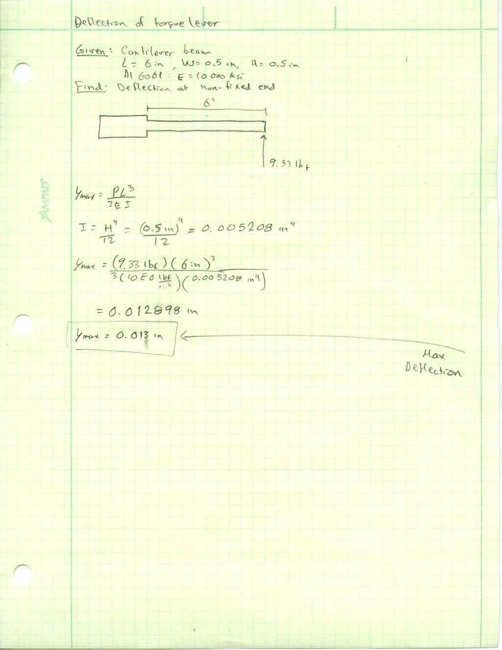
8 Performance Predictions: All components are predicted to fit well within the existing lab setup and without adding too much extra weight. Also, because all parts of this device except the bolts and bearings are made of an aluminum alloy, it is predicted that this device will not rust and it will maintain a clean surface finish. Once this device is fully built and functional, it is predicted that the motor will apply a force of around 6 lb f on the load cell. This will lead to a torque calculation of 36 in-lb on the top end. It is also predicted that the torque lever will stay within its elastic modulus throughout the testing process, which will prolong its lifetime. This lab will always be housed indoors and therefore temperature changes do not have to be taken into account when designing it. This means the components will not exposed to extreme temperatures that could affect their performance. Description of Analyses: Platform Lever: In order to design the lever that will transfer the torque from the motor and place a force on the load cell, the predicted load on the cell has to be calculated (T=FD). Then pick the length and height of the lever and calculate the width using stress = M/S where S = WH 2 /6 and M is the maximum moment on the lever. The max deflection at the non-fixed end will be calculated in order to decide if the calculated dimensions are enough for a small deflection. Bolts: The bolts will not be machined, but the right diameter still has to be chosen to prevent failure. The bearing housing plate has to be bolted to the lab set up platform; the motor platform has to be bolted to the side plates that will hold the shaft that sits on the bearings. Use the equations F = 2T/D, shear = 2T/DNA, and diameter of bolt = (8T/DN*pi*shear) 1/2. Shaft: The shaft on which the motor platform sits is subjected to a shear force. In order to prevent failure the diameter has to be calculated using shear = F/surface area. The force depends on the weight of the motor and its components plus the reaction force from the torque arm. Bearing Housing: The bearing housing is subjected to the compressive load of the motor and other components. It is a 1.5 plate and with components lighter than 20lbs there is no need to worry about these plates failing. 7
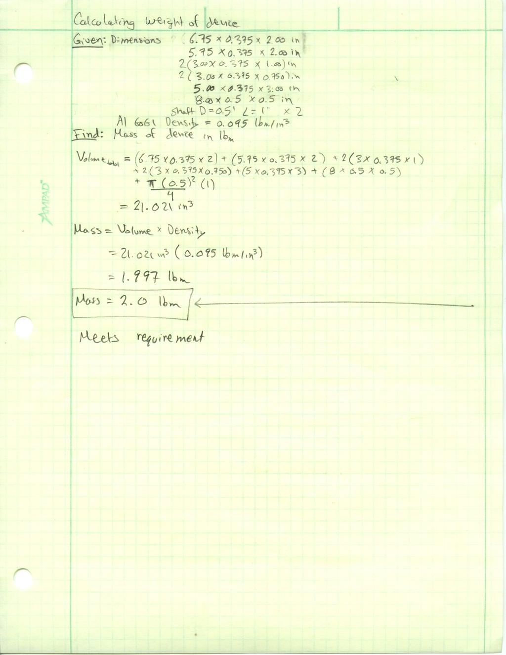
9 Scope of Testing and Evaluation: The impact tester can be used to test the key manufactured for the coupler. This can ensure that the key will not fail while students are working on the lab. The same test can be done to the torque arm. Analyses: Solve for the diameter of the bolts that will be used to attach the torque arm to the shaft and also solve for the geometry of the torque arm. The diameter for the bolts that hold the motor to the platform that swivels on bearings also have to be calculated. The diameter of the shaft that sits on the bearings has to be solved for. Take into account that these calculations have to use a safety factor of 1.5 and that the material used is Aluminum In order not to add too much weight the total weight of the device can be calculated in solid works along with the surface area to see how much space it will take up. Device: Parts, Shapes, and Conformation: The professor who offered this project wants the final device to withstand rust and have a fine clean finish. Because of this then the chosen material is aluminum. It is easy to machine and the final surface finish is almost like it was polished and it also will not rust. In order to achieve this, when the parts are machined a high spindle speed and slow feedrate will be used. Device Assembly and Attachments: This device has three main sections of parts. The load cell will be wired to the digital display, the wires will be soldiered to provide a good connection. The torque arm will be machined and bolted to the bottom of the motor platform. The platform where the motor will sit is the main focus. The endplate will have to be drilled together with the platform to ensure hole concentricity. The holes on the platform endplate and bearing housing will be drilled and reamed to provide good hole concentricity and a tighter fit for when the bearings and shafts are pressed in. The motor platform can be assembled prior to bolting the device to the lab set up platform. Tolerances, Kinematics, Ergonomics: Every hole, diameter, and overall length of any part should be machined to within in order to guarantee that the edges and corners of this device will line up. This will also ensure a proper press fit for the shaft onto the side plate of the platform and between the bearing and the bearing housing plate. If the holes are drilled to this tolerance they will not properly align and the fitment of the parts will look crooked. This will also ensure that the platform where the motor sits will be as parallel as possible to the bottom platform and provide a better power transfer and not add any unwanted stresses on the device and motor shaft. 8
10 Technical Risk Analysis, Failure Mode Analysis, Safety Factors, Operation Limits: In order to machine the parts for this device it has to be taken into account that the MET 355 class leaves their projects in the CNC machines throughout the quarter and there usually is not much room to load projects while they are running their class projects. It is important to keep track of how the advanced machining class is doing and when they leave the CNC machines open for others. The same has to be taken into account for the MET 255 class since most of the time they use the lathes and the manual milling machines. Another risk is the availability of funds for the components of the project. For the most part aluminum is relatively cheap and hardware can be obtained from the CWU shop at no cost. Since this is a project that will stay at CWU to be used by students the department may donate funds or materials to complete this project. One way this device may fail is if the motor is started prior to placing the torque lever on the load cell. If this happens then the lever will strike the load cell or the steel platform and the lever may bend or break and may also break the load cell. This is a critical load scenario where the torque arm and the load cell will experience a higher load than they were designed for. If extra weight is placed on the motor platform then the shaft that sits on the bearings may experience a higher load than it was designed for, this will create a higher shear force than it can handle and therefore it may shear. For this reason all parts must me designed with a safety factor of 1.5 at a minimum. It is important to only use this device with the specified motor in the lab. It is not designed to withstand the torque from motors bigger than those used in the thermodynamics lab. It is also important to keep any other lab materials from hitting and damaging the load cell. This will prevent any part of the device from failing and it will extend the lifetime of the device. It is also important to keep dust and fluids from falling on the bearings since this may build up gunk or wash away the lubricant in the bearings and shorten their lifetime. 9
11 Methods and Construction: Description: Every component asides from the hardware is made out of aluminum /8 plate or round stock. The bearing housing has bearings that slide in and will be fixed with epoxy or Loctite. The bearing housing will be welded to a platform that will bolt down to the lab setup. The motor platform has a shaft housing with the shaft pressed in and welded; this shaft slides into the bearings in the bearing housing. There are two motor bolt plates that bolt up to the top and bottom existing tapped holes on the rear of the motor. On the right end of the motor platform the torque arm is bolted using two bolts. This torque arm will press down on a load cell. There are three main subassemblies. The first consists of the motor platform which is made up of the motor platform base with a side plate that has a shaft pressed in. There are two motor plates that hold the motor. All of these parts are bolted down with hardware that will be purchased. The second subassembly consists of the bearing housing that has bearings pressed in. The third subassembly only consists of the torque lever which will be bolted to the motor platform. 10


12 Drawing Tree: Bo5om Support Top Support Bo5om Bolt Plate Rear Bolt- up Top Bolt Plate Hardware Torque Arm Bearing Housing Plate Final Assembly Bearing Plate Two Bearings Hardware Bo5om Plate Load Cell Base Cell base Hardware Load Cell ShaA Housing Side Plate ShaA Parts List and Labels: Refer to Appendix C for a detailed parts list; it contains all the information necessary to complete the build. Manufacturing Issues: Instead of using socket cap screws to assemble this device, all the parts that go together will be welded. One possible problem is welding misaligned parts, if this happens the parts will 11
13 have to be machined from scratch again. Although bolting the parts together is a safer route, this does not provide a rigid structure and is more prone to fatigue failure over time. Another issue that can get in the way is not turning the shafts to the right diameter. If the outer diameter is too large then it will be hard to press them into the platform side plates. If the outer diameter is too small then the shafts will slide out of the platform side plate. This issue can also affect their fitment into the bearings. If the hole for the bearings is too big then the bearings will slide out. If this happens, the bearing housing is useless and has to be machined again from the beginning. A slide fit is optimal to increase the life of the bearings, a very tight interference fit will create too many stresses in the bearing housing and the bearings themselves. While setting up the lathe to bore the hole for the bearings a problem was encountered. The 4-jaw chucks available at the CWU shop do not provide the proper clearance in the back to bore the hole for the bearing housing. Fortunately the shop has an indexable boring head for the milling machine and that fixed a problem. One big problem that was encountered is related to the electrical portion of this project. The load cell obtained was very cheap and therefore it is not of the best quality. This load cell does not put out the required precision for the load value. Because this motor is only rated at 36 lb-in of max running torque, a small change in the load read by the load cell can mean a large change in the torque value. Therefore a better quality load cell is required and this cost may be over the set budget. Assembly, Sub-assembly, Parts, Drawings: It is important that all the machining is precise for the assembly to go smoothly. The assembly has a required sequence, which allows the components to fit correctly. The assembly goes as follows: 1. The torque arm will be machined. The holes will be drilled on the milling machine for precision. 2. The platform side plate will be machined. The shaft hole will be drilled and reamed. The shaft will be turned to match the hole and then pressed in. The holes on the top will be drilled on the mill or drill press. 3. The motor bolt plates will be machined. Machined to precision on the mill. The holes will be drilled on the mill or drill press. The holes will be tapped by hand. 4. The motor platform will be machined and assembled. The platform will be machined on the mill, the holes will be drilled to match those of the motor bolt plates. The side plate will be bolted to the platform (Can weld if possible). The bolt plates will be bolted to the platform. The torque arm will be bolted to the platform. 5. The bearing housing plate will be machined. Machined to precision on the mill. 12
14 Holes will be drilled and tapped by hand. The bearing hole will be drilled and reamed. The bearings will be pressed in. Bottom plate will be machined on the mill, holes will be drilled. Bolt or weld bearing housing to bottom plate. 6. Bolting assembly to the main lab set up platform. The bearing housing bottom plate will be bolted to the main lab setup platform then the shaft from motor platform will slide into the bearings. The load cell base will be machined, holes will be drilled and tapped (by hand). 13
15 Testing Method Introduction: A testing method was established in order to prove that the device built will measure the torque of the motor to within reasonable values. A parallel beam load cell is used and it seems that it may give different load values if the load is placed on different sections of the load cell. Also, the weight of the whole device including the load cell, the digital read out, and the hardware must be five pounds or less. Asides from those two requirements, the main requirement that was tested for is the torque value, which was supposed to be +-2 lb-in of the manufacturer s specifications. When testing the load cell the values obtained will be from a static load, and the weight will be a reading from a scale. The torque values will be obtained from running the air motor hooked up to the water pump at a set inlet pressure while limiting the RPM by closing the outlet of the water pump. Method: In order to run any tests several things are needed. First, the lab rig and all components must be obtained. This includes water tank, hoses, RPM meter, calibration weights, oil mister, and the lab rig with water pump fitted with inlet and outlet pipes. A source of compressed air is very important as well as a second person to help with reading and calling out values. A scale is needed to weight the device and a jig must be made to test the load cell. The values from the torque test will be put into excel. These values include RPM, load, and length of torque arm. Using excel the torque can be calculated as well as the horsepower and both of these values can be graphed where RPM is on the X-axis and torque and horsepower are on the Y-axis. To weigh the device it must first be removed from the rig and place everything on the scale at once including the load cell and readout. In order to test the load cell a jig that fits concentric with the holes on the cell must be machined. Finally, to test the whole device the air motor will be ran in conjunction with the water pump and a water source, which is the source that will place a load on the motor allowing it to produce torque. Due to safety reasons there are some limitations on the operation of this device. The air motor and the water pump are quite old and therefore it may not be safe to push the motor to 3000 RPM at an inlet pressure of 100 psi. At an inlet pressure of just 60 psi the pressure at the outlet of the water pump rises to over 100 psi when the valve is closed in order to lower the RPM and obtain load cell values at lower RPM. The precision of the torque values will be affected by the precision to which the length of the torque arm was machined; it will also be affected by the accuracy of the load cell and the precision to which the digital readout calculates the load values. The precision to which the components are machined will not affect the overall performance of the device, except for the concentricity of the bearings with the motor s shaft, but this can be easily adjusted. The data will be presented in tables and graphs. The test for the load cell will have several load values of different sections of the load cell and they will be organized in a table. The weight of the device is not as important yet it will be placed in a table comparing the requirement and the actual value. The torque values will be calculated in a spreadsheet and presented in a table and a graph. 14
16 Procedure: Load Cell Calibration: The load cell used is a parallel beam load cell and therefore there is not center spot where the load should be placed. Because of this one is not sure where to place the load in order to obtain the best results. This test can be done anywhere as long as the load cell, digital readout, calibration weight (200g was used), test jig, and battery are present. This test can take up to two hours including the machining time spent making the test jig. For this test access to the machine shop is required. Weight of Device: This is a simple test to check for a requirement. This requirement was placed in order to keep the lab rig as light as possible. Overall it will not affect the torque results. The portion that could affect the torque values is all the components that turn with the air motor, that includes both rear bolt plates, upper and lower supports, torque arm, shaft housing, shaft and nut, and all the bolts and pins. Because all these components turn with the bearings which are practically a frictionless surface it is like the motor has no extra mass to turn. This test can be done anywhere where a scale is available and it should take no more than 45 minutes including tear down and reassembly time. Torque Measurement: For this test not every sensor on the lab rig is needed. The only components needed are the motor, water pump, some hoses, oil mister, water tank, compressed air, RPM meter, and the torque measuring device. This test can take between two to three hours depending on the knowledge of how everything is hooked up. See Appendix H for test results procedures and Appendix I for test results. 15
17 Deliverables: The final results are mass values in pounds, load cell values in grams, and torque values in lb-in. In order for these torque values to be considered successful then they must be within 5% of the manufacturer s specifications. If the values are father off then it must be due to concentricity issues, and the electronic components being of low quality. A parallel beam load cell seems like a new thing around this department and nobody had good input on them. Using a button load cell is simple since the load just has to be centered on it. On the parallel beam load cell there is enough surface area that the load can be moved around. What is not known is if the load reading will change if the load is placed on different spots on the load cell. Because of this a test was designed. This test would define if the load cell would have to be fixed in place or allowed to move freely while running the lab. In the end it was discovered that no matter where the load was placed the load reading did not change, but only by a few grams. This change in the load reading will not make a big impact on the overall torque calculations since those loads are expected to be a couple thousand grams. The lab rig itself is quite a heavy object and therefore it was set forth that the torque measuring device must not weigh over five pounds. There was no clear prediction of how much the whole device would weigh since in the end it would not affect the workability of the device. It was more of a requirement to keep in mind and not something to really try to achieve. In the end the device ended up being around 4.80 lb. For the torque calculations a test was devised in order to try and match the manufacturer s torque specs. The manufacturer provided a graph of the torque at different inlet pressures and through the maximum limit of RPM. The graphs in Appendix I show the results. These results are not close at all to what the manufacturer specified. This is due to the motor and water pump being a little old, but mostly because the electronic components, that is the load cell and digital readout are not of the highest quality and therefore do not produce accurate results with good repeatability. These two items are far more accurate with a static load, but when vibrations are added the digital readout cannot keep up with the changes in load on the load cell. The best way to fix this problem is to somehow connect the load cell to a data logger program such as LabVIEW and take a moving average to get rid of all the noise. 16
18 Budget/Schedule/Project Management Proposed Budget: This is a small project that requires a small amount of materials and therefore the budget is calculated to be $ The funding for this project will come out of the student s pocket and perhaps some materials may be obtained from the department since this project will stay here at CWU. Most of the materials including aluminum plates, bearings, load cell, and digital display will be bought off of ebay. An itemized list including material, quantity, and cost can be found in Appendix C. All the machining and assembly labor will be done at the CWU machine shop, which provides the necessary tooling and environment to complete these processes. No labor for this project will be outsourced, this allows for a smaller budget. Proposed Schedule: A tentative schedule that is subject to change was created to help organize this project and ensure that it will be completed on time. This schedule is located in Appendix D. The schedule outlines the steps and time it took to write up the proposal. It points out the main tasks and in some cases subtasks. It is broken up into three sections, one for each quarter. The quarter in which the project is built is organized in a way so that the project is finished by the end of the quarter if the outlined schedule is followed. The schedule also points out milestones, in order to stay on track those milestones need to be reached by the deadline. The estimated time to complete the manufacturing portion of this project is 101 hours. Project Management Human Resources: There is one other student working on this same project each on their own. There will be two projects all with the same purpose. Talking to each other helps bounce off ideas and make sure that the project will have a good outcome. Physical Resources: The CWU machine shop and machining instructors will be influential when it comes to machining anything in the most efficient way. Soft Resources: SolidWorks is an incredible tool to help design this project. It allows for quick editing of current designs or for a complete new design to be brought to life. 17
19 Conclusion This device is designed to measure the torque output of the air motor for the thermodynamics class laboratory. The design is appropriate because it is made of a material that will not rust, the device does not interfere with any other part of the lab setup, and the output reading has a resolution appropriate for the data calculations involved with the lab. The Mechanical Engineering department here at CWU offers classes such as machining, welding, mechanical design, and strength of materials. These classes teach the necessary skills required to design and build this project. The mechanical engineering department also offers enough resources such as the machine shop, which contains enough tools and materials to machine the parts for the torque measuring device. Acknowledgements Acknowledgements of gratitude go out to the following people who have helped at different stages of this project. Professor Beardsley for providing this project. Classmates Sergio Flores, David Sedano, and Jose Garcia for their help with SolidWorks. Classmate Logan for his continuous updates on the requirements of the project. Professor Johnson and Pringle for their input on the proposal. Matt Burvee and Ted bramble for their input on machining the project. 18
20 Appendix A: Analyses Image 1: Torque Lever Dimensions. 19

21 Image 2: Failure of ½ pin. Image 3: Minimum pin diameter. 20

22 Image 4: Tensile force on lever bolts. 21
23 Image 5: Coupling bolts diameter 22

24 23

25 Image 6: Key geometry 24

26 Image 7: Lever deflection ¼ cross section 25
27 Image 8: lever deflection ½ cross section 26
28 27

29 Image 9: Platform deflection 28

30 Image 10: Platform shear moment diagrams 29
31 Image 11: Weight of device 30
32 31

33 Image 12: Shaft shear moment diagrams 32

34 Appendix B: Drawings Figure 1: Bearing Housing. 33

35 Figure 2: Bearing Housing Platform. 34

36 Figure 3: Front Motor Plate. 35

37 Figure 4: Rear Motor Plate. 36

38 Figure 5: Motor Platform. 37

39 Figure 6: Platform Lever.

40 Figure 7: Shaft. 39

41 Figure 8: Shaft Housing. 40

42 Figure 9: Load Cell Base. 41

43 Figure 10: Motor Platform Assembly.
44 APPENDIX C Parts List Parts ID/Drawing # Shaft S1 Bearings (x2) BRGS Front Motor Plate FMP Rear Motor Plate RMP Shaft Housing SH Bearing Housing Platform BHP Motor Platform MP Platform Lever PL Load Cell LC Load Cell Display LCD Bolts BLT Load Cell Base LCB Bearing Housing Plate BHP2 43
45 APPENDIX D Budget Material Application Part ID Suppl Quantity Price/Unit Subtotal ier Al Shaft S1 CWU 2 x3 0 0 Round stock 6061 Al Platform PL CWU 4.8 x3 x Flat plate Lever 6061 Al Flat plate Ebay 2x(3/8 x4 x14 ) 8 16 Hardware Bearings Load Cell Digital Load Cell Display Platform & Bearing Housing Bolting everything together Hold motor platform Measure load Display load on cell FMP, RMP, PSP, SH, BHP, MP, LCB BLT CWU 15(1/4x20 bolts) 0 0 BRGS Ebay LC Ebay LCD Ebay Total


46 APPENDIX E Schedule 45
47 APPENDIX H Testing Report Introduction: A testing method was established in order to prove that the device built will measure the torque of the motor to within reasonable values. A parallel beam load cell is used and it seems that it may give different load values if the load is placed on different sections of the load cell. Also, the weight of the whole device including the load cell, the digital read out, and the hardware must be five pounds or less. Asides from those two requirements, the main requirement that was tested for is the torque value, which was supposed to be +-2 lb-in of the manufacturer s specifications. When testing the load cell the values obtained will be from a static load, and the weight will be a reading from a scale. The torque values will be obtained from running the air motor hooked up to the water pump at a set inlet pressure while limiting the RPM by closing the outlet of the water pump. Method: In order to run any tests several things are needed. First, the lab rig and all components must be obtained. This includes water tank, hoses, RPM meter, calibration weights, oil mister, and the lab rig with water pump fitted with inlet and outlet pipes. A source of compressed air is very important as well as a second person to help with reading and calling out values. A scale is needed to weight the device and a jig must be made to test the load cell. The values from the torque test will be put into excel. These values include RPM, load, and length of torque arm. Using excel the torque can be calculated as well as the horsepower and both of these values can be graphed where RPM is on the X-axis and torque and horsepower are on the Y-axis. To weigh the device it must first be removed from the rig and place everything on the scale at once including the load cell and readout. In order to test the load cell a jig that fits concentric with the holes on the cell must be machined. Finally, to test the whole device the air motor will be ran in conjunction with the water pump and a water source, which is the source that will place a load on the motor allowing it to produce torque. Due to safety reasons there are some limitations on the operation of this device. The air motor and the water pump are quite old and therefore it may not be safe to push the motor to 3000 RPM at an inlet pressure of 100 psi. At an inlet pressure of just 60 psi the pressure at the outlet of the water pump rises to over 100 psi when the valve is closed in order to lower the RPM and obtain load cell values at lower RPM. The precision of the torque values will be affected by the precision to which the length of the torque arm was machined; it will also be affected by the accuracy of the load cell and the precision to which the digital readout calculates the load values. The precision to which the components are machined will not affect the overall performance of the device, except for the concentricity of the bearings with the motor s shaft, but this can be easily adjusted. The data will be presented in tables and graphs. The test for the load cell will have several load values of different sections of the load cell and they will be organized in a table. The weight of the device is not as important yet it will be placed in a table comparing the requirement and the actual value. The torque values will be calculated in a spreadsheet and presented in a table and a graph. 46
48 Procedure: Load Cell Calibration: The load cell used is a parallel beam load cell and therefore there is not center spot where the load should be placed. Because of this one is not sure where to place the load in order to obtain the best results. This test can be done anywhere as long as the load cell, digital readout, calibration weight (200g was used), test jig, and battery are present. This test can take up to two hours including the machining time spent making the test jig. For this test access to the machine shop is required. 1. On the lathe turn a disk out of aluminum 0.25 inches thick and 1.25 inches in diameter. 2. Drill a hole to press fit a bolt or a pin equal to the diameter of the holes on the load cell. Cut the head off of the bolt before pressing it in. 3. Obtain a nut and thread it onto the bolt all the way up to the disk. This will concentrate the load over a smaller surface area. 4. Place the test jig into the front hole on the load cell. Zero out the load cell. 5. In the digital readout menu select the mass of the calibration weight to be used. 6. Center the weight on the jig and press both the function and right buttons on the load cell. 7. Record the value on the readout. 8. Repeat steps 4-7 for the rear hole and record the value. The test can be repeated with different calibration weights and it can be repeated several times and the results can be averaged. Weight of Device: This is a simple test to check for a requirement. This requirement was placed in order to keep the lab rig as light as possible. Overall it will not affect the torque results. The portion that could affect the torque values is all the components that turn with the air motor, that includes both rear bolt plates, upper and lower supports, torque arm, shaft housing, shaft and nut, and all the bolts and pins. Because all these components turn with the bearings which are practically a frictionless surface it is like the motor has no extra mass to turn. This test can be done anywhere where a scale is available and it should take no more than 45 minutes including tear down and reassembly time. 1. Unbolt the device from the rear of the motor and from the lab rig platform. 2. Do not take the device itself apart. 3. Remove the load cell and readout from the lab rig. 4. Obtain a scale with a range of at least 15 lbs. 5. Zero out the scale and place the torque device, load cell, digital readout, and hardware on the scale. 6. Record this value and compare it to the requirement of 5 lbs. Torque Measurement: For this test not every sensor on the lab rig is needed. The only components needed are the motor, water pump, some hoses, oil mister, water tank, compressed air, RPM meter, and the torque measuring device. This test can take between two to three hours depending on the knowledge of how everything is hooked up. 47
49 1. Obtain the components and bolt the torque device to the back of the motor and to the lab platform. 2. Use a calibration weight to calibrate the load cell before placing it under the torque arm. 3. Fix the load cell under the torque arm and tightly press a piece of rubber on the pivot arm on the opposite side of the torque arm. 4. Hookup the oil mister to the inlet of the motor and to the compressed air source. Maintain both valves fully closed. 5. On the oil mister preset the inlet pressure to 20 psi. For better results slowly open the air inlet valve to the motor to full throttle as you set the inlet pressure. 6. Slowly open the air inlet valve to full throttle as you slightly close the water outlet valve to keep the motor from revving up to high revolutions. 7. Use the valve for the water outlet on the water pump to control the RPM. 8. Close the water outlet valve until you reach a desired RPM. This RPM can range from 1000 to Record load values from the load cell read out at three different RPM for three trials each. 10. Repeat steps 5-9 for 40 psi and 60 psi. Any higher inlet pressure can be potentially dangerous. 11. Insert load, and RPM readings along with the length of torque arm (3.250) into an excel spreadsheet. 12. Calculate the torque by multiplying the load and length of the torque arm. Convert units to lb-in if desired. 13. Graph Torque vs. RPM and Horsepower vs. RPM. See Appendix I for test results. Deliverables: The final results are mass values in pounds, load cell values in grams, and torque values in lb-in. In order for these torque values to be considered successful then they must be within 5% of the manufacturer s specifications. If the values are father off then it must be due to concentricity issues, and the electronic components being of low quality. A parallel beam load cell seems like a new thing around this department and nobody had good input on them. Using a button load cell is simple since the load just has to be centered on it. On the parallel beam load cell there is enough surface area that the load can be moved around. What is not known is if the load reading will change if the load is placed on different spots on the load cell. Because of this a test was designed. This test would define if the load cell would have to be fixed in place or allowed to move freely while running the lab. In the end it was discovered that no matter where the load was placed the load reading did not change, but only by a few grams. This change in the load reading will not make a big impact on the overall torque calculations since those loads are expected to be a couple thousand grams. The lab rig itself is quite a heavy object and therefore it was set forth that the torque measuring device must not weigh over five pounds. There was no clear prediction of how much the whole device would weigh since in the end it would not affect the workability of the device. 48
50 It was more of a requirement to keep in mind and not something to really try to achieve. In the end the device ended up being around 4.80 lb. For the torque calculations a test was devised in order to try and match the manufacturer s torque specs. The manufacturer provided a graph of the torque at different inlet pressures and through the maximum limit of RPM. The graphs in Appendix I show the results. These results are not close at all to what the manufacturer specified. This is due to the motor and water pump being a little old, but mostly because the electronic components, that is the load cell and digital readout are not of the highest quality and therefore do not produce accurate results with good repeatability. These two items are far more accurate with a static load, but when vibrations are added the digital readout cannot keep up with the changes in load on the load cell. The best way to fix this problem is to somehow connect the load cell to a data logger program such as LabVIEW and take a moving average to get rid of all the noise. 49
51 APPENDIX I Testing Data Test 1: Load cell calibration data Trial Calibration Weight Hole 1 Load (g) Hole 2 Load (g) g g g Test 2: Mass of device and hardware Test 3: Torque calculations Trial Mass (lb) Average
52 Torque calculated during first trial at 40, 50, and 60 psi inlet pressures Torque at Constant Inlet Pressures Torque (lb- in) psi 50 psi 60 psi RPM Horsepower calculated during first trial at 40, 50, and 60 psi inlet pressures Horsepower at Constant Inlet Pressures Horsepower psi 50 psi 60 psi RPM 51
53 Torque calculated during second trial at 40, 50, and 60 psi inlet pressures Torque at Constant Inlet Pressures Torque (lb- in) psi 50 psi 60 psi RPM Horsepower calculated during second trial at 40, 50, and 60 psi inlet pressures. 52
54 Horsepower at Constant Inlet Pressures Horsepower psi 50 psi 60 psi RPM 53
55 APPENDIX J Resume Jose Bejar 2102 N Walnut St Apt 21 Ellensburg, WA jbejar91@hotmail.com Cell: (509) Objective I am a Mechanical Engineer Technology student seeking a position as EDUCATION Bachelor of Science University of Washington, Seattle, WA Mechanical Engineering Degree not completed Bachelor of Science Central Washington University, Ellensburg, WA Mechanical Engineering Technology 2014-Now Relevant Skills Personal Skills Ability to work independently and collaboratively. High level of organization. Ability to follow instructions orally or written. Computer Skills SolidWorks AutoCAD MATLAB Visual Basic Java Mechanical Aptitude Programming for Milltronics CNC Mill Programming for Milltronics CNC Lathe Bridgeport Mill 54
56 Manual Lathe Employment History Central Washington University, Ellensburg WA Sept 2015-Now Lab Technician for the MET Department Handle the material for the basic and advanced machining classes. Help students with their MET255 (Basic Machining) projects. Maintain the shop clean Work on assigned projects by my supervisor. RAM Mounts, Seattle, WA Sept-Dec 2013 Machine Operator As part of a team of around five people we managed up to eight injection-molding machines at times in a fast paced environment. We made sure the machines never stopped running by keeping the raw material flowing from the hoppers and making sure the parts were coming out within the quality specifications. Mold Rite Inc., Woodinville, WA July-Sept 2012 Assembly Line Worker Assembled parts that came off of the injection molding machines, checked for quality, counted and packaged them. Worked in the tool room milling parts, checking for quality, and packaging them. 55
Stationary Bike Generator System
 Central Washington University ScholarWorks@CWU All Undergraduate Projects Undergraduate Student Projects Spring 2017 Stationary Bike Generator System Rakan Alghamdi Central Washington University, rk_rk11@hotmail.com
Stationary Bike Generator System (Drive Train)
") Central Washington University ScholarWorks@CWU All Undergraduate Projects Undergraduate Student Projects Summer 2017 Stationary Bike Generator System (Drive Train) Abdullah Adel Alsuhaim cwu, 280zxf150@gmail.com
Central Washington University ScholarWorks@CWU All Undergraduate Projects Undergraduate Student Projects Summer 2017 Stationary Bike Generator System (Drive Train) Abdullah Adel Alsuhaim cwu, 280zxf150@gmail.com
Pin Router Duplicator Base
 Central Washington University ScholarWorks@CWU All Undergraduate Projects Undergraduate Student Projects Spring 2017 Pin Router Duplicator Base Matthew Tebo tebom@cwu.edu Follow this and additional works
Hydraulic Sprayer Boom Upgrade
 Central Washington University ScholarWorks@CWU All Undergraduate Projects Undergraduate Student Projects Spring 2016 Hydraulic Sprayer Boom Upgrade Chad R. Omlin Central Washington University, chadomlin@gmail.com
Technical Math 2 Lab 3: Garage Door Spring 2018
 Name: Name: Name: Name: As you may have determined the problem is a broken spring (clearly shown on the left in the picture below) which needs to be replaced. I. Garage Door Basics: Common residential
Cassette Lockring Removal Tool
 Central Washington University ScholarWorks@CWU All Undergraduate Projects Undergraduate Student Projects Spring 2018 Cassette Lockring Removal Tool Kyle Wright Central Washington University, kylegwright@comcast.net
ASME Human Powered Vehicle
 ASME Human Powered Vehicle By Yousef Alanzi, Evan Bunce, Cody Chenoweth, Haley Flenner, Brent Ives, and Connor Newcomer Team 14 Mid-Point Review Document Submitted towards partial fulfillment of the requirements
PYRTE. Building The Front Axle, Fork and Steering
 PYRTE Building The Front Axle, Fork and Steering The front axle on this traction engine is a very simple affair, in that it is a rectangular steel rod, sat on edge, with a pivot in the centre, which is
For Immediate Release
 For Immediate Release Hydraulic cylinders reconditioned quickly and efficiently with low-cost honing system machine pays for itself in less than a year Machine saves many cylinders from going to scrap
*Some speedometers have these additional electronic connections. If yours does, then remove the smaller slotted screws shown.
 www.odometergears.com 1981-1985 240 Cable-Driven Speedometers (NOT for 1986 and later electronic units) http://www.davebarton.com/240-odometer-repair.html For this set of instructions below, I will not
Modular Engine 1, 2008 revision August 3, 2008
 Modular Engine 1, 2008 revision August 3, 2008 David Kerzel 2008 Back in 2002 I wanted to build a bunch of different engines without a lot of detail to learn how to build an engine, what works and what
Remote Control Helicopter. Engineering Analysis Document
 Remote Control Helicopter By Abdul Aldulaimi, Travis Cole, David Cosio, Matt Finch, Jacob Ruechel, Randy Van Dusen Team 04 Engineering Analysis Document Submitted towards partial fulfillment of the requirements
High Accessibility Cabinet Insert
 Central Washington University ScholarWorks@CWU All Undergraduate Projects Undergraduate Student Projects Summer 2017 High Accessibility Cabinet Insert Matthew Leal Central Washington University, lealm@cwu.edu
I cannot believe it has been so long since my last update. A lot has happened and I will try to bring everyone up to speed. First of all, I had my
 I cannot believe it has been so long since my last update. A lot has happened and I will try to bring everyone up to speed. First of all, I had my left knee replaced about 5 weeks ago. Needless to say
Load cells for a Portable Structure
 Load cells for a Portable Structure Load Restoring force Side force We know that a weighing system must be rigid to get good results. We should also know that a three point system is inherently more stable
13 October, 2014 Page 1
 13 October, 2014 In my second and last Helicycle I want to make everything better than the first one. That includes not only a transmission chip detector, but one for the tail rotor as well. The transmission
M:2:I Milestone 2 Final Installation and Ground Test
 Iowa State University AerE 294X/AerE 494X Make to Innovate M:2:I Milestone 2 Final Installation and Ground Test Author(s): Angie Burke Christopher McGrory Mitchell Skatter Kathryn Spierings Ryan Story
Orchard Bin ATV Trailer
 Central Washington University ScholarWorks@CWU All Undergraduate Projects Undergraduate Student Projects Spring 2016 Orchard Bin ATV Trailer Neil F. Leitz Central Washington University, leitzneil@gmail.com
Your web browser (Safari 7) is out of date. For more security, comfort and. the best experience on this site: Update your browser Ignore
 is out of date. For more security, comfort and. the best experience on this site: Update your browser Ignore") Your web browser (Safari 7) is out of date. For more security, comfort and Activitydevelop the best experience on this site: Update your browser Ignore Circuits with Friends What is a circuit, and what
Your web browser (Safari 7) is out of date. For more security, comfort and Activitydevelop the best experience on this site: Update your browser Ignore Circuits with Friends What is a circuit, and what
Next, chase the threads in the lower A-arm mounts with the 5/8-18 tap and blowout any remaining particles.
 Next, chase the threads in the lower A-arm mounts with the 5/8-18 tap and blowout any remaining particles. Now, apply some anti-seize to the threads of the pivot stud. Also put anti-seize inside the bore
Suspension for Electrathon Vehicle
 Central Washington University ScholarWorks@CWU All Undergraduate Projects Undergraduate Student Projects Spring 2016 Suspension for Electrathon Vehicle MacKenzie Ericson Angeledes mangeledes@gmail.com
BMW 2002 M42 Swap Notes-THIS IS NOT FINISHED
 BMW 2002 M42 Swap Notes-THIS IS NOT FINISHED This document is to help those that want to install an m42 into a BMW 2002. It is based around an e30 engine, trans, and wiring. You can use the e36 block/head/wiring
Door Panel Removal & Window Stop Adjustment
 Door Panel Removal & Window Stop Adjustment By: Jeff Wolford Disclaimer: This is simply an article of how I fixed my car. I m not responsible if you break, scratch, or mess up anything following my example.
RC Baja Car Suspension
 Central Washington University ScholarWorks@CWU All Undergraduate Projects Undergraduate Student Projects Spring 2018 RC Baja Car Suspension Tyler Martin Central Washington University, tylermartintjm@gmail.com
Troubleshooting Guide for Okin Systems
 Troubleshooting Guide for Okin Systems More lift chair manufacturers use the Okin electronics system than any other system today, mainly because they re quiet running and usually very dependable. There
"Top Ten" reasons to measure: 10. To Provide Proper Sheet Metal Fit
 Important Reasons why your collision shop needs to Measure. This is one of the most important functions of collision repair and it is a Must Do Process for the success of your business. by Tom Brandt Whether
SAE Mini BAJA: Suspension and Steering
 SAE Mini BAJA: Suspension and Steering By Zane Cross, Kyle Egan, Nick Garry, Trevor Hochhaus Team 11 Progress Report Submitted towards partial fulfillment of the requirements for Mechanical Engineering
Paper Airplane Building Machine: Paper Loading, Power Source, Machine Frame
 Central Washington University ScholarWorks@CWU All Undergraduate Projects Undergraduate Student Projects Spring 2016 Paper Airplane Building Machine: Paper Loading, Power Source, Machine Frame Abdullah
Balancing the Wheels on a Bench Grinder, version 2
 Balancing the Wheels on a Bench Grinder, version 2 By R. G. Sparber Copyleft protects this document. 1 I recently replaced the wheels on my bench grinder and the vibration was horrible. With a lot of help
Introduction: Problem statement
 Introduction: Problem statement The goal of this project is to develop a catapult system that can be used to throw a squash ball the farthest distance and to be able to have some degree of accuracy with
Adjustable Shelving Unit for Home Beer Brewing
 Central Washington University ScholarWorks@CWU All Undergraduate Projects Undergraduate Student Projects Spring 2017 Adjustable Shelving Unit for Home Beer Brewing Andrew L. Kastning kastninga@cwu.edu
ASME RC Baja Car: Suspension and Chassis
 Central Washington University ScholarWorks@CWU All Undergraduate Projects Undergraduate Student Projects Spring 2017 ASME RC Baja Car: Suspension and Chassis C. Aidan Pringle Central Washington University,
MSI SINGLE IDLER BELT SCALE
 MSI SINGLE IDLER BELT SCALE Instruction Manual PL-319 January 2001 33453190 Rev. 1.2 Safety Guidelines Warning notices must be observed to ensure personal safety as well as that of others, and to protect
LG CORVETTE GT2 COIL OVERS
 LG CORVETTE GT2 COIL OVERS THE MOST POWERFUL HEADERS ON THE PLANET Brought to you by LG Motorsports 972-429-1963 Parts Inventory: 1. Assembled Front shock and spring 2. Assembled Rear shock and spring
Porsche 928 with 16v LH-Jetronic Fuel System
 Porsche 928 with 16v LH-Jetronic Fuel System Toll-Free Tech Hot Line: 877-FOR-928M 877-367-9286 Please do not copy this manual and give copies to your friends. Our ability to bring you this supercharger
Roehrig Engineering, Inc.
 Roehrig Engineering, Inc. Home Contact Us Roehrig News New Products Products Software Downloads Technical Info Forums What Is a Shock Dynamometer? by Paul Haney, Sept. 9, 2004 Racers are beginning to realize
PFadvantage MF 6850/6855; Ideal 9080/9090
 MF 6850/6855; Ideal 9080/9090 Note: Indented items indicate parts included in an Quantity by Model assembly listed above MF Ideal Part Name/Description Part Number 6850 6855 9080 9090 Instruction Kit MF
Troubleshooting Guide for Limoss Systems
 Troubleshooting Guide for Limoss Systems NOTE: Limoss is a manufacturer and importer of linear actuators (motors) hand controls, power supplies, and cables for motion furniture. They are quickly becoming
Instruction Manual August milltronics MSI BELT SCALE
 Instruction Manual August 2003 milltronics MSI BELT SCALE Safety Guidelines Warning notices must be observed to ensure personal safety as well as that of others, and to protect the product and the connected
Development of Relief Valve Automatic assembly technology
 Development of Relief Valve Automatic assembly technology Technology Explanation Development of Relief Valve Automatic assembly technology TAKIGUCHI Masaki Abstract Construction machinery is equipped with
DODGE OFF ROAD T-STYLE STEERING KIT INSTALLATION INSTRUCTIONS
 Dodge Off Road, LLC Specializing in Dodge Ram Solid-Axle 4x4 Suspension and Steering for Off Road Applications 855.9009.DOR sales@dodgeoffroad.com dodgeoffroad.com DODGE OFF ROAD T-STYLE STEERING KIT INSTALLATION
ASME Mini-Baja RC CAR (Steering and suspension systems)
") Central Washington University ScholarWorks@CWU All Undergraduate Projects Undergraduate Student Projects Spring 2016 ASME Mini-Baja RC CAR (Steering and suspension systems) Michael E. Cox Central Washington
Central Washington University ScholarWorks@CWU All Undergraduate Projects Undergraduate Student Projects Spring 2016 ASME Mini-Baja RC CAR (Steering and suspension systems) Michael E. Cox Central Washington
Actual CFM = VE Theoretical CFM
 Here is a brief discussion of turbo sizing for a 2.0 liter engine, for example, the 3-SGTE found in the 91-95 Toyota MR2 Turbo. This discussion will compare some compressor maps from the two main suppliers
Folding Shopping Cart Design Report
 Folding Shopping Cart Design Report EDSGN 100 Section 010, Team #4 Submission Date- 10/28/2013 Group Image with Prototype Submitted by: Arafat Hossain, Mack Burgess, Jake Covell, and Connor Pechko (in
DIY balancing. Tony Foale 2008
 DIY balancing. Tony Foale 2008 I hope that the main articles on the theory behind engine balance have removed the mystic which often surrounds this subject. In fact there is no reason why anyone, with
feature 10 the bimmer pub
 feature 10 the bimmer pub BMW E90 Steering Angle Sensor Diagnosis A pattern failure may indeed point you to a bad component, but when the part is expensive you want to be very sure it s the culprit before
Hub Stands -- VERSION 5.0
 Hub Stands -- VERSION 5.0 Thanks for choosing our Alignment Hub Stands for your chassis setup needs. We hope you'll find them as handy, accurate, and easy to use as we do! Each stand has a max capacity
SHOCK DYNAMOMETER: WHERE THE GRAPHS COME FROM
 SHOCK DYNAMOMETER: WHERE THE GRAPHS COME FROM Dampers are the hot race car component of the 90s. The two racing topics that were hot in the 80s, suspension geometry and data acquisition, have been absorbed
The Pneumatic Leg Extension
 Central Washington University ScholarWorks@CWU All Undergraduate Projects Undergraduate Student Projects Spring 2016 The Pneumatic Leg Extension David G. Sedano Central Washington University, sedanod@cwu.edu
PRESEASON CHASSIS SETUP TIPS
 PRESEASON CHASSIS SETUP TIPS A Setup To-Do List to Get You Started By Bob Bolles, Circle Track Magazine When we recently set up our Project Modified for our first race, we followed a simple list of to-do
Engine Management System
 Engine Management System 6 0 4-0 0 1 I N S T R U C T I O N S For 2005-2007 Harley-Davidson FL Models 2 Revolution Performance was founded with two major goals in mind to go that extra mile providing a
GM A-Body Instructions 3 & 2½ Header Applications w/ Balance Tube Crossover
 GM A-Body Instructions 3 & 2½ Header Applications w/ Balance Tube Crossover Included with this kit are the following: 2 Collector Reducers 1 Balance Tube Kit A 2 Headpipes 2 Tailpipes 2 Tailpipe Extensions
Gearbox Assembly 101. Introduction. Before Beginning. By Mark Schutzer 4/13/06
 Gearbox Assembly 101 By Mark Schutzer 4/13/06 Introduction If you are planning to re-motor an old brass locomotive you may want to upgrade to a new gearbox at the same time. The early 60 s and 70 s gearboxes
ESS INSTALL. The donor car /6 Cosmos Black/Sand UUC Short Shifter Brembo cross drilled rotors Phillips Nav System 16:9
 ESS INSTALL The donor car.. 1997 540/6 Cosmos Black/Sand UUC Short Shifter Brembo cross drilled rotors Phillips Nav System 16:9 The install went in several stages. Disconnect the battery Stage 1 Remove
Implementation Notes. Solar Group
 Implementation Notes Solar Group The Solar Array Hardware The solar array is made up of 42 panels each rated at 0.5V and 125mA in noon sunlight. Each individual cell contains a solder strip on the top
MNBRATKIT MidNite Brat Solar Charging Kit
 1 pc MNBRAT 20/30-amp PWM Charge Controller 1 pc MNBIGBABY Breaker Box 3 pcs 1-10A 1-20A 1-30A MNEPV- PV, Battery and Load Breakers 2 pcs 2 pcs 9-161-1 Strain Relief 9-162-1 Lock Nut 2-4 Hole Strain Reliefs
Instructions to install the early ( ) Limited Slip Differential in the Late-model ( ) G28 Transaxle
 Limited Slip Differential in the Late-model ( ) G28 Transaxle") Instructions to install the early (1978-83) Limited Slip Differential in the Late-model (1985-1995) G28 Transaxle BACKGROUND: Most 928 owners know about the improvements to the 5- speed transaxle that
Instructions to install the early (1978-83) Limited Slip Differential in the Late-model (1985-1995) G28 Transaxle BACKGROUND: Most 928 owners know about the improvements to the 5- speed transaxle that
4x4 actuator "Cable Froze" 1988 s S-10 Forum
 Page 3 of 17 Converting a vacuum actuator to a locking cable system on a 1995 Chevy S10 Blazer 4x4 Many call this a posi-lock system. I spent a total of only $25.50 USD on this project. Other comparable
Physics 2048 Test 2 Dr. Jeff Saul Fall 2001
 Physics 2048 Test 2 Dr. Jeff Saul Fall 2001 Name: Group: Date: READ THESE INSTRUCTIONS BEFORE YOU BEGIN Before you start the test, WRITE YOUR NAME ON EVERY PAGE OF THE EXAM. Calculators are permitted,
NARCOA CUSTOM-BUILT & HIGHLY- MODIFIED MOTORCAR GUIDELINES
 NARCOA CUSTOM-BUILT & HIGHLY- MODIFIED MOTORCAR GUIDELINES VERSION 1.6 October 2006 INTRODUCTION and INTENT - This handbook was developed to create a set of guidelines that provides inspectors, excursion
Shotgun Single Barrel HPFP install guide
 Shotgun Single Barrel HPFP install guide Thank you for your purchase of the VTT Shotgun Single Barrel HPFP upgrade! First thing to do when you open your box is to make sure all parts are in their respective
Air Compressor/Water Pump IV - Pilot Valve Stem, Test & Installation
 Page 1 of 8 Air Compressor/Water Pump Part IV Pilot Valve Stem, Test & Installation Nelson Riedel Nelson@NelsonsLocomotive.com Initial: 1/13/04 Last Revised: 0 Valve Test: I decided to test the steam valves
4TH GEN SEATS IN A 3RD GEN TRUCK
 4TH GEN SEATS IN A 3RD GEN TRUCK by Flopster843 02 Oct 2016 If you drive a 3rd generation Dodge Ram truck, I am sure you have discovered that the OEM seats are not the greatest (Figure 1.) They are extremely
Engineering Diploma Resource Guide ST280 ETP Hydraulics (Engineering)
") Engineering Diploma Resource Guide ST80 ETP Hydraulics (Engineering) Introduction Hydraulic systems are a fundamental aspect of engineering. Utilised across a variety of sectors including aviation, construction,
Engineering Diploma Resource Guide ST80 ETP Hydraulics (Engineering) Introduction Hydraulic systems are a fundamental aspect of engineering. Utilised across a variety of sectors including aviation, construction,
HexPro Series Low Profile Wrenches
 HexPro Series Low Profile Wrenches Operation and Maintenance Manual Model 2HP 4HP 8HP 14HP 30HP www.torquetoolsinc.com Use the HEXPRO Series Low Profile Wrenches Model 2HP 4HP 8HP 14HP 30HP to install
Piping Design. From the METTLER TOLEDO Weigh Module Systems Handbook
 Piping Design Any time that piping is connected to a tank scale (a dead-to-live connection), there is a potential for mechanical binding. If piping is not installed properly, it can cause weighing errors
Exercise Machine Generator
 Central Washington University ScholarWorks@CWU All Undergraduate Projects Undergraduate Student Projects Spring 2018 Exercise Machine Generator Duane Harbick harbickd@cwu.edu Follow this and additional
TMS Trailing Arm Race Bushings
 PART # TSU9980020 TMS Trailing Arm Race Bushings TMS Trailing arm race bushings replace the stock rubber bushings, and were developed in conjunction with the TMS SPEED World Challenge Racing Team. Over
AMT Motorsport C7 Corvette Camber Kit User s Guide. 8 Upper Control Arm Studs and hardware for rear upper control arm adjustments
 AMT Motorsport C7 Corvette Camber Kit User s Guide Thank you for purchasing the AMT Motorsport Camber Kit for the C7 Corvette. We believe this is the most versatile camber kit available on the market,
Interlocks 325 Series
 rd 12070 43 St. NE, St. Michael, MN 55376 763-497-7000 www.tcamerican.com sales@tcamerican.com Installation Instructions Interlocks 325 Series 3I-615; 3I-430 3I-613; 3I-450 Crane Interlock and Operating
Using Hydraulic Systems
 Lesson A6 7 Using Hydraulic Systems Unit A. Mechanical Systems and Technology Problem Area 6. Agricultural Power Systems Lesson 7. Using Hydraulic Systems New Mexico Content Standard: Pathway Strand: Power,
Orbital Test Stand. By Mary Begay, Brett Booen, Calvin Boothe, James Ellis and Nicholas Garcia. Team 7. Project Proposal Document
 Orbital Test Stand By Mary Begay, Brett Booen, Calvin Boothe, James Ellis and Nicholas Garcia Team 7 Project Proposal Document Submitted towards partial fulfillment of the requirements for Mechanical Engineering
DC Series Installation Manual (# )
") DC Series Installation Manual (# 101630) Page 1 of 33 In this booklet you will find: TOWER INSTALLATION... 3 U-Bolt Style mount... 4 Side Frame Style mount... 4 PIVOT INSTALLATION... 5 External Pivot Installation:
DC Series Installation Manual (# 101630) Page 1 of 33 In this booklet you will find: TOWER INSTALLATION... 3 U-Bolt Style mount... 4 Side Frame Style mount... 4 PIVOT INSTALLATION... 5 External Pivot Installation:
OPTIMIZATION & ANANLYSIS OF A HEAVY VEHICAL CHASSIS USING COMPOSITE MATERIALS
 OPTIMIZATION & ANANLYSIS OF A HEAVY VEHICAL CHASSIS USING COMPOSITE MATERIALS U.NANDINI 1, C.PARIMALA 2, K.SAI KEERTHI 3 1,2,3 Assist. professor, department of mechanical engineering, Anantha Lakshmi Institute
Utility Trailer 5 x 8 Building Notes
 Utility Trailer 5 x 8 Building Notes This is a standard utility trailer model that is currently on the market (at least in Minnesota). The price tag seems to average around $900 - $1100. There is no doubt
Busy Ant Maths and the Scottish Curriculum for Excellence Foundation Level - Primary 1
 Busy Ant Maths and the Scottish Curriculum for Excellence Foundation Level - Primary 1 Number, money and measure Estimation and rounding Number and number processes Fractions, decimal fractions and percentages
Stephenson's Valve Gear: 7mm cast white-metal kit 19 th Century swing-link version - non-working, cosmetic only. Instructions
 SER-Kits Stephenson's Valve Gear: 7mm cast white-metal kit 19 th Century swing-link version - non-working, cosmetic only Page 1 of 5 Instructions HEALTH & SAFETY: The castings contain some lead. Dispose
MicroGuard 586 Retrofit Rated Capacity Indicator System. Calibration and Testing for:
 GREER COMPANY Page 1 of 22 MicroGuard 586 Retrofit Rated Capacity Indicator System Machine Model Serial Number Tester Date Calibration and Testing for: GREER COMPANY Page 2 of 22 MicroGuard 586 Retrofit
How to replace or adjust the altitude clutch of the NexStar N11GPS
 Langenbrettach/Germany, February 10 th 2004 Matthias Bopp How to replace or adjust the altitude clutch of the NexStar N11GPS Table of content How to replace or adjust the altitude clutch of the NexStar
TWO-STAGE HYDRAULIC PUMP. RWP55-IBT-Air
 ORIGINAL INSTRUCTIONS Form No.1000458 5 SPX Corporation 5885 11th Street Rockford, IL 61109-3699 USA Tech. Services: (800) 477-8326 Fax: (800) 765-8326 Order Entry: (800) 541-1418 Fax: (800) 288-7031 Internet
June 23, 2014 Page 1
 My engine looks pretty clean but this fuel pump and fuel control assembly looked really nasty. I decided to partially tear them down and clean them up. This is what the asssembly looked like to begin with.
INSTALLATION INSTRUCTIONS
 COLD AIR INTAKE INSTALLATION INSTRUCTIONS PART NUMBER D760-0390C APPLICATION: 1999-2003 E39 M5 PARTS LIST 1 Left Aluminum Intake Tube 1 Air Pump Bracket (A) 1 Right Aluminum Intake Tube 1 Air Pump Bracket
CAPTUREPRO USER GUIDE FOR TESLA MODEL S, MODEL X, AND MODEL 3. Updated: September Power12 and CapturePro by Power12 Company v1.
 CAPTUREPRO FOR TESLA MODEL S, MODEL X, AND MODEL 3 USER GUIDE Updated: September 2018 Power12 and CapturePro 2013 2018 by Power12 Company v1.2 Table of Contents CapturePro Purpose and Design... 3 Why was
Amarillo PUMP DRIVES (250 HP THROUGH 350 HP) INSTRUCTIONS FOR REPAIRING MODELS 250, 300, and 350
 INSTRUCTIONS FOR REPAIRING MODELS 250, 300, and 350") Amarillo PUMP DRIVES (250 HP THROUGH 350 HP) INSTRUCTIONS FOR REPAIRING MODELS 250, 300, and 350 Amarillo Right Angle Pump Drives, if properly installed and maintained, should provide years of service
Amarillo PUMP DRIVES (250 HP THROUGH 350 HP) INSTRUCTIONS FOR REPAIRING MODELS 250, 300, and 350 Amarillo Right Angle Pump Drives, if properly installed and maintained, should provide years of service
Applications in Design & Engine. Analyzing Compound, Robotic Machines
 v2.1 Compound Machines ering Applications in Design & Engine Analyzing Compound, Robotic Machines Educational Objectives At the conclusion of this lesson, students should be able to: Understand the relationship
In order to discuss powerplants in any depth, it is essential to understand the concepts of POWER and TORQUE.
 -Power and Torque - ESSENTIAL CONCEPTS: Torque is measured; Power is calculated In order to discuss powerplants in any depth, it is essential to understand the concepts of POWER and TORQUE. HOWEVER, in
AQA GCSE Physics. 55 minutes. 55 marks. Q1 to Q4 to be worked through with tutor. Q5 to Q7 to be worked through independently.
 AQA GCSE Physics Magnetism & Electromagnetism 4.7.. - 4.7.2.: Magnets & Electromagnets Name: Class: Date: Time: 55 minutes Marks: 55 marks Comments: Q to Q4 to be worked through with tutor. Q5 to Q7 to
Delivering Dependable Service Through Proactive Vehicle Management
 Delivering Dependable Service Through Proactive Vehicle Management Sales and Delivery Fleet Improves Vehicle Health and Reduces Idling Interstate Batteries, a leading supplier of batteries to thousands
Newton s 2 nd Law Activity
 Newton s 2 nd Law Activity Purpose Students will begin exploring the reason the tension of a string connecting a hanging mass to an object will be different depending on whether the object is stationary
CHECK AND CALIBRATION PROCEDURES FOR FATIGUE TEST BENCHES OF WHEEL
 STANDARDS October 2017 CHECK AND CALIBRATION PROCEDURES FOR FATIGUE TEST BENCHES OF WHEEL E S 3.29 Page 1/13 PROCÉDURES DE CONTRÔLE ET CALIBRAGE DE FATIGUE BANCS D'ESSAIS DE ROUE PRÜFUNG UND KALIBRIERUNG
FD Transmission Rebuild: Parts Inspection
 FD Transmission Rebuild: Parts Inspection Now that everything is disassembled, cleaned, and bagged in labeled Zip-Locs, it s time to decide what to replace. Warning: I m not a transmission specialist I
PORSCHE V r Valve Timing Instructions. Copyright 2009 Written by Mike Frye Edited my Adam G.
 PORSCHE 928 32V r Valve Timing Instructions Copyright 2009 Written by Mike Frye Edited my Adam G. Sections: Overview.3 Disclaimer/warnings/things to watch for 4 Terms and naming conventions used in this
Canadian Manufacturer of Quality Weighing Systems
 Sept., 2005 Product Update Thank you for purchasing your load beam scale system from Massload Technologies. We genuinely hope that this system will provide years of trouble free operation in your application
Application Note. Monitoring Bearing Temperature with ProPAC
 Monitoring Bearing Temperature with ProPAC Introduction A mechanical stamping press usually has two or more main bearings for supporting the crankshaft and for allowing smooth and accurate rotation. There
Safety factor and fatigue life effective design measures
 Safety factor and fatigue life effective design measures Many catastrophic failures have resulted from underestimation of design safety and/or fatigue of structures. Failure examples of engineered structures
J&M Mustang Adjustable Panhard Rod (05-09) - Installation Instructions
 - Installation Instructions") J&M Mustang Adjustable Panhard Rod (05-09) - Installation Instructions The below installation instructions work for the following products: J&M Mustang Adjustable Panhard Rod (05-09) Please read through
J&M Mustang Adjustable Panhard Rod (05-09) - Installation Instructions The below installation instructions work for the following products: J&M Mustang Adjustable Panhard Rod (05-09) Please read through
Throttle Cable Pull - Patent Pending By: NetGain Controls, Inc.
 Throttle Cable Pull - Patent Pending By: NetGain Controls, Inc. Powering the future! Installation Guide 2011 All Rights Reserved NetGain Controls, Inc. 1 of 8 Introduction Thank you for purchasing a NetGain
LETTER TO PARENTS SCIENCE NEWS. Dear Parents,
 LETTER TO PARENTS Cut here and paste onto school letterhead before making copies. Dear Parents, SCIENCE NEWS Our class is beginning a new science unit using the FOSS Magnetism and Electricity Module. We
Simple Gears and Transmission
 Simple Gears and Transmission Simple Gears and Transmission page: of 4 How can transmissions be designed so that they provide the force, speed and direction required and how efficient will the design be?
Interlocks 200 Series
 rd 12070 43 St. NE, St. Michael, MN 55376 763-497-7000 www.tcamerican.com sales@tcamerican.com Installation Instructions Interlocks 200 Series 2I-515; 2I-930 2I-513; 2I-850 Crane Interlock and Operating