Cassette Lockring Removal Tool
|
|
|
- Penelope West
- 5 years ago
- Views:
Transcription

1 Central Washington University All Undergraduate Projects Undergraduate Student Projects Spring 2018 Cassette Lockring Removal Tool Kyle Wright Central Washington University, Follow this and additional works at: Part of the Applied Mechanics Commons, and the Manufacturing Commons Recommended Citation Wright, Kyle, "Cassette Lockring Removal Tool" (2018). All Undergraduate Projects This Undergraduate Project is brought to you for free and open access by the Undergraduate Student Projects at It has been accepted for inclusion in All Undergraduate Projects by an authorized administrator of For more information, please contact
2 Cassette Lock Ring Removal Tool By Kyle Wright
3 Table of Contents: 1. Introduction Pg. 4-5 a. Description b. Motivation c. Function Statement d. Requirements e. Success Criteria f. Scope 2. Design and Analyses Pg. 5-8 a. Device Sketch b. RADD c. Further Analysis of Device 3. Methods and Construction Pg a. Manufacturing b. Manufacturing Issues/Modifications c. Assembly d. Engineering Disciplines/Relevant Equations e. Device Operation f. Benchmark Comparison g. Performance Predictions 4. Testing Method Pg a. Testing b. Test Plan c. Torque Reduction of Device d. Comparison of Device to Traditional Methods 5. Budget/Schedule/Project Management Pg a. Cost and Budget b. Schedule c. Project Management 6. Discussion Pg Conclusion Pg Acknowledgements Pg Appendix A Pg Appendix B Pg Appendix C Pg Appendix D Pg Appendix E Pg Appendix F Pg
4 Abstract: Removal of a bicycle cassette requires additional tools to hold the cassette in place while loosening the cassette lockring. Typically a tool called a chain whip is used to stabilize the cassette, but is difficult to quickly and correctly apply to the cassette. Due to the need for an additional tool to hold the cassette, the user is faced with utilizing both hands while still needing to somehow hold the wheel in place. The lockring is torqued relatively tight and the overall combination of force, ergonomics, and number of tools required makes the task difficult to perform quickly. The objective was to create a device that simultaneously holds the cassette in place while also loosening the lockring thus eliminating the need for a chain whip. This device also utilizes a gear set to reduce user imputed toque. By using the cassette s mechanical function of non-clockwise free rotation in relation to the wheel itself, a stable motionless platform is created to apply a moment in clockwise direction while a torque multiplying gear set converts the clockwise rotation to counter clockwise rotation which loosens the lockring. User applied torque is reduced by 50% compared to traditional methods. The device also increases the ergonomics of the task and improves overall task completion time by 33%. Eliminating the use of a separate cassette holding tool improves simplicity of the task. 3
5 1: Introduction Description On a multi speed bicycle a component called a cassette is located on the drive side of the rear wheel. This component is an assortment of usually 7 to 11 different sized sprockets that are part of the drivetrain of the bicycle. The drive chain can be indexed onto any single one of the sprockets to achieve different gear ratios as desired by the rider. There are two issues with the process of removing a cassette from a bicycle rear wheel. First issue, it takes considerable force to loosen the cassette lock ring. Second, tools that require the use of both hands are needed during loosening of the cassette lock ring. Motivation The ergonomic challenges that bike mechanics and at home DIY bike enthusiasts face while trying to remove a cassette from a rear bike wheel give motivation for development of a new set of processes and tools. One of the tools that is particularly difficult to use in the current method is called a chain whip. A chain whip is lever arm that has two pieces of a bicycle chain attached to one end. A short section of chain about three links long has both ends fixed to one side of the lever arm. The second piece of chain is about 10 links long and one end is attached at the same end of the lever arm as the shorter piece of chain. To use the chain whip, the user will set the short section of chain on a sprocket in the cassette, preferably in the middle of the cassette. The chain will need to be lined up so the cogs will engage the chain just as the drive chain would normally. It is important for initial placement to be on the left side of the cassette if it is facing the user. The long piece of chain will then be wrapped around the same sprocket in the counter clockwise direction. At this point a lock ring tool attached to a ratchet or breaker bar would be set into the lock ring and then be loosened in the counter clockwise direction. The need to use a chain whip to secure the cassette during the task is a source of awkward body positioning and numerous possibilities of poor tool placement. This also leads to an increased amount of energy needed to break the locking loose due to common sub optimal positioning of the tools being used. All of these issues contribute to more time needed to complete the task as well. Function Statement A device that will allow single handed removal of a bicycle cassette. Requirements Loosen lock ring that is torqued to 30 ft lb Reduce user torque impute by 50% (15 ft lb) Smaller than 6 x3 x2 in size Compatible with 3/8 drive tools Compatible with Shimano style cassette lock rings 4

6 Can hang on a tool board in a shop or garage setting Takes less than 6 seconds to grab tool and perform the task. Success Criteria The project is deemed successful if these criteria are met: Reduces user input force by 50% Loosens lock ring torqued to 30 ft lb Task is performed faster than with other tools and methods Testers feel the tool is equal to or superior overall compared to other tools and methods Scope The design focus is on the device and not the actual tools that are used in conjunction with the device. These tools are the ratchet wrench or breaker bar and the tool that interfaces directly with the cassette lock ring. The project is not dealing with automatic tools such as pneumatic and electric motors. This is to focus on keeping the size down along with overall weight. It is typical for tools in a bike shop to be hung on a tool board against a wall and one goal is having the ability to hang the tool on a wall or tool board. 2: Design & Analysis Preventing the counter clockwise rotation of the cassette is the main challenge when removing the lock ring. The cassette will freely spin only in the counter clockwise direction and will not rotate unless the entire wheel rotates in the clockwise direction. The idea for the device relies on applying a moment in clockwise rotation so the cassette does not rotate while a gear set converts that clockwise rotation into counter clockwise rotation to loosen the lock ring. The gear set can also provide a higher gear ratio to decrease the force required to loosen the lock ring. Early Device Sketch 5
7 A drawing in Appendix B1.1 shows what will essentially be the frame of the device. It is the Bearing Carrier and will be two halves that bolt together to contain the gear set and bearings. RADD Requirement Device must reduce user torque input by 50% Analysis A standard bicycle cassette lock ring is torqued to 30 ft.lb. A 50% reduction of this torque is equal to 15 ft.lb. The ratio between the two torque values is 2:1 Design A 32 tooth gear and 16 tooth pinion gear were selected for the application. This produces the exact same 2:1 ratio required through the calculations. Documentation Calculations for the analysis are located in Appendix A1.1 Requirement 1566 carbon steel gear shaft with a key seat must withstand a torque of 30 ft.lb. Analysis Finding the minimum diameter of the shaft for this scenario will provide a benchmark of the smallest size to be used in the design. The material yield strength is psi but this value is reduced due to the shear stress experienced during torsion. This value is then further reduced due to the stress concentration of the key seat. The allowable shear stress factor applied to the yield strength is due to the distortion energy theory. This shear stress is then reduced by 25% to accommodate for the key seat according to the Machinery s Handbook 30 th ed. In the end the design stress is now psi from the original psi. Using the equation 3 for Diameter of a solid circular shaft required to transmit a given torque DD = (5.1TT/SSSS) the minimum diameter can now be calculated. Design The calculations revealed the benchmark for the smallest shaft diameter to support the 30 ft.lb. torque was 0.384in. The smallest diameter on the gear shaft for the design is 0.480in which is 25% over the benchmark. Documentation Full calculations for the analysis can be found in Appendix A1.4. Requirement - 3 pins of a fixed size must be made of a material that can sustain a direct shear force Analysis - The area of the pin is 0.078in 2 and the total force spread between the 3 pins is calculated to be lb. Solving for the shear stress divided by the 3 pins is psi/pin. Design - From the analysis calculations it was determined a material with a shear strength greater than 1736psi would be suitable for the application steel was selected with a shear strength of 30480psi which produces a safety factor of over 17. This is more than necessary but the material is readily available and has good manufacturability. Documentation - The full break down of the calculations can be found in Appendix A1.7 Further Analysis of Device Axial Force (Thrust Load) Helical gears produce an axial force which requires some type of bearing, shoulder, or other means of supporting this force. In Appendix A1.2 an analysis is performed to determine the axial force produced by the gear set selected for the device. These thrust loads can then be used to determine what kind of thrust bearings are suitable for the application. 6

8 Radial Load When under load, a gear set will produce a radial force that acts perpendicular to the axis of rotation and opposite of the other gear. Appendix A1.3 provides the calculations for this force. Minimum Key Length One key per gear is used to fix the gears to the shafts and transmit the torque. The key way built into the gears being used is inches in length and a key the entire length of the key way is utilized. Calculations determining the safety factor of this design are shown in Appendix A1.5. Shaft Key Seat Depth Key seats are machined into the gear shafts and the optimal depth of the key seat needed to be determined. In Appendix A1.6 the calculations for these key seats are shown. Gear and Pinion Shaft Stress and Deflection The radial force produced by the gear set subjects the gear shafts to stresses and deflections similar to that of a loaded beam. Appendix A1.8 shows the calculations of the stress and deflection experienced by the gear shafts due to the radial loads. Moment Created During Device Use The device will require a lever arm to help the user produce the initial torque input to the pinon shaft. Due to the device having an overall thickness greater than a traditional wrench and lock ring tool setup (example shown in Image A.1), the applied force by the user is great enough that a moment is generated that causes a tendency for the device to rotate perpendicular to the rotating axis of the lock ring. This moment does have an effect on the stability of the device when engaged into the cassette and lock ring. A similar scenario is when a ratchet with a long extension, say 5 inches or greater is used to loosen or tighten a bolt. Without any support of the tool close to the bolt, the socket will try to cam off of the bolt head. Appendix A1.9 provides calculations representing this possible unstable scenario when using the device. Standard Wrench Standard Lock Ring Tool Image A1 7
9 Cog Holding Plate Locating Bolts Shear Stress A plate holds the pins that contact and grip the 11 tooth cog that ultimately holds the cassette in place. This plate can slide up and down the rotating axis of the gear shaft via shoulder bolts. These bolts must withstand the force of the tool wanting to rotate when the lock ring is being loosened. Appendix A1.10 provides the calculations for the shear stress that one bolt would experience if it was the only bolt preventing the rotation. Potential Lever Arm Deflection The current modeled and design of the device does not utilize a built in lever arm. However, if the need arises for the integrated lever Appendix A1.11 shows calculations predicting the deflection of a possible lever arm design that would utilize any leftover materials. Shear Stress on Assembly Plate Screws The screws that hold down the assembly fixing plates are subjected to shear forces produced by the helical gear set s thrusts loads. Appendix A1.12 presents the calculations of the shear stress in direct shear that one of the screws is subjected too and makes any future changes to screw material simpler by establishing the magnitude of the stress experienced. 3: Methods & Construction Other than the initial vision of this project, the analysis and design was carried out at the CWU campus. The device is a collaboration of pre-manufactured components and parts machined on the CWU campus. Pre-manufactured parts were purchased from various vendors and were typically of complex geometries or assemblies. A list of the parts can be found in Appendix C1.1. Parts made on the CWU campus were made from raw materials or modifications of previously existing components. Manufacturing Manual machining on a lathe and mill along with CNC machining were used to produce essentially all of the parts that were not purchased. Below are images and videos of some of these parts during and after manufacturing. 8

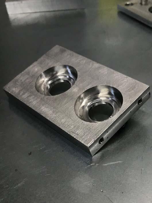
10 Top Bearing Carrier 9

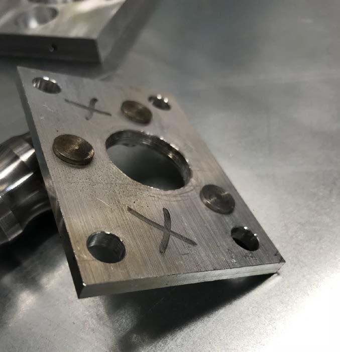
11 Cog Holding Plate 10


12 Gear Shaft 11


13 Manufacturing Issues/Modifications During manufacturing, multiple issues were discovered and presented their own challenges. The first issue to arise was holding of the different work pieces in the lathe. All of the cylindrical parts in the device are rather small and do not leave much room for secure and accurate clamping of the work piece as well as room for the machine tool. Improved process and procedures help alleviate this issue by leaving the material stock full size and machining the part completely then cutting it off the stock material. This provided lots of stock material for work holding and would leave plenty of material accessible for machining. Image 3.1 displays the improved work holding setup. Image
14 Another issue was the change in material hardness of the modified cassette tool after it had been welded to the gear shaft. The material became very hard and the turning tools had much difficulty when machining light cuts. The tool tip would simply break or chatter against the material and create uneven rough looking cuts. Unfortunately there was no way to fix the hardness problem in a timely fashion so the rough finish would remain but it has no effect on the overall function of the device. During the welding process, there was a slight overlap of weld splatter that effected the key seat machined into the shaft. Once again, this is something that should have been done last instead of earlier in the manufacturing process Assembly The main parts purchased from suppliers are the two helical gears, thrust bearing assemblies, open ball bearing assemblies, keys, and external retaining rings. Components that are made on campus are the two gear shafts, top and bottom bearing carrier plates, cog holding plate assembly, and modifications to a previously existing cassette locking tool. Manufacturing will be completed in a specific order. First, the bearing carrier plates will be machined and the open ball bearings will be press fit into their respective holes on the plate. Second, the gear shafts will be turned and milled to achieve the appropriate features. Third, the thrust bearings, helical gears, bearing carrier, and gear shafts will be assembled together and secured by external retaining rings. A visual tree diagram of the main assemblies can be seen in the beginning of Appendix B. Tolerances for the press fit application of the bearings in the top and bottom bearing carriers was certainly a learning experience. The relative light load demands and almost non-existent speeds during the use of the device made it clear that even with matching diameters, the bearings and bores for the bearings would have been a plenty tight fit. Instead, the bearing carriers were machined to be undersize of the bearing outer diameter. This made installation of the bearings more difficult than originally thought. Even with heating of the bearing carrier and cooling the bearings, the fit was still rather tight and would make any future removal of the bearings difficult. When final assembly of the device was done it was apparent that the spacing between the bearing carriers was slightly smaller than what was needed to fit the shaft assemblies set of thrust washers, bearings, and the gear all in-between the two bearing carriers. Luckily the thrust washer assemblies each use two washers that are only thick each. Removing one washer from one thrust assembly per shaft remedied the clearance issue. 13

 14")
15 Assembled Device Assembled Device (no fixing plates) 14

16 Device Sub-Assemblies Layout Top Bearing Carrier Assembly Gear Shaft Assembly Bottom bearing Carrier Assembly Pinion Shaft Assembly Engineering Disciplines/Relevant Equations Engineering discipline areas of interest for the project include statics, strength of materials, and machine design in general. Equations used multiple times for the design and analysis are Direct Shear ττ = FF 3, Torque TT = FFdd, and Diameter of Shaft for Given Torque DD = (5.1TT/SSSS). These AA and other related equations were used to help optimize design parameters of several components of the device including bolt sizes, minimum shaft diameters, and appropriate gear ratios. Device Operation Operation of the cassette lock ring tool device requires completion of a short sequence of tasks. First, the cassette lock ring socket needs to be placed into the cassette lock ring while keeping the cog holding plate and its pins from touching the cassette. Second, index the cog holding plate s 3 pins in-between teeth on the 11 tooth cassette cog (the first and smallest cog on the cassette). The cog holding plate can side up and down in relation to the bottom of the device body along with rotating the body of the device to help align the pins. It is essential that the cassette lock ring socket and cog holding plate pins are both nested into their respective positions before proceeding to the next step. With one hand hold and stabilize the outer diameter of the wheel and 15
17 with the other hand use a 16mm socket on a breaker bar or ratchet wrench to turn the pinion shaft on the top side of the tool in a clockwise direction. The device body which is now fixed in place to the cassette should not move due to the cassettes inability to rotate clockwise in relation to the rest of the wheel being stationary. It is at this time that the clockwise rotation of the pinon shaft will rotate the gear shaft in the counter clockwise direction. The cassette lock ring socket is fixed to the end of the gear shaft and will loosen the cassette lock ring. Benchmark Comparison This device is unique in its approach to performing its task compared to all other traditional methods. There is also no available ratings or previously quantified performances associated to other procedures. The amount of force to loosen the cassette lock ring disregarding lever length is the main aspect that can be improved and benchmarked against other methods without post design testing for comparison. For these reasons the focus of the design was based on not only reducing user effort but also improving the ergonomics of the task and overall time to complete the task. Performance Predictions - The force that the user will have to input to loosen the lock ring is estimated to be 50% of what is currently the standard. - The time to perform the entire task of loosening and removing the cassette lock ring cannot be accurately calculated but based on the device design it is estimated that the task will take at the worst 100% the time as other methods and could potentially be far faster based on user familiarity with other methods. - The ergonomic performance of the device again cannot be calculated before testing but it is highly possible considering the issues and difficulties associated with traditional tools and methods that the device will receive high remarks from testers of its ease of use. 4: Testing Method Testing: Testing of the device was carried out at the CWU campus. Due to the size and basic requirements of the device, no complicated equipment was necessary to complete testing. Test Plan: The particular parameters of interest are the function of the tool when being used. This is mostly focusing on the ability for the tool to loosen the torqued lockring, reducing the user impute torque, and how fast can the tool perform the task. Predictable outcomes of the tools performance are the reduction in torque input, relatively time to perform task, and the overall ability to even loosen the lockring. Data was acquired throughout testing in order to evaluate the final performance of the tool and compare to the requirements established at the beginning of the project. The approach to testing of the tool was to evaluate the most important aspects that the tool was designed to accomplish. These aspects are based around functionality of the tool and less on the weight or storage conveniences like mentioned in the requirements. Resources needed for proper evaluation were measurement tools like a torque wrench, stop watch, basic hand tools ranging 16
18 from wrenches to specific bike tools, location for testing, and most importantly human testers to use the tool in real world applications. Data was collected for all testing for further analysis. Torque Reduction of Device: The first test was an evaluation of the effectiveness of the gear set used in the tool. An overview of the test procedure is as follows: -Using a rear bicycle wheel with a cassette mounted, torque cassette lockring to 30 ft-lb using a torque wrench -Using the traditional cassette removal tools and a torque wrench with a reversible ratcheting function, loosen the lockring using the torque wrench instead of a standard wrench. -Set the torque wrench to 29 ft-lb and attempt to loosen the lockring increasing the torque setting by 1/2 ft-lb increments until the lockring breaks loose. -Perform the test 3 times and record the values for each test. -Now using the device, perform the same procedure recording the torque value for each test that the lockring loosens at. The precision of this test is limited to the precision of the torque wrench being used. Performing multiple tests helps establish better data. With the data an average torque value can be computed from each set of trials for both the traditional lockring removal tools and the device. The parameter value of this test was the torque. Calculated values were the average torque per method and the percentage difference between the two. Success criteria values were deemed by being within 5% of the benchmark value. In conclusion of the tests, the results show that the device is well within 5% of the benchmark value of 15 ft-lb or 50% of the torque that the lockring was initially torqued to. The device required an average of ft-lb of torque to remove the lockring which is within 1% of 15 ft-lb benchmark. Comparison of Device to Traditional Methods: This test will be used to evaluate the effectiveness of the device against the traditional method of cassette lock ring removal in a regular bicycle shop setting. The task is to remove the lockring on a bicycle cassette. Time to perform the task will be recorded for each method with multiple trials to establish consistent results. A detailed procedure for the test can be found in Appendix E. Results of the test show that out of 3 testers all 3 had a faster time for lockring removal using the device vs. the traditional method. As a group average the device improved there times by 29.3%. 5: Budget/Schedule/Project Management This project has a number of risks as would any project of this nature. Costs, budget, schedule, and project management are the main aspects of this risk analysis. Cost and Budget: 17
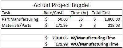
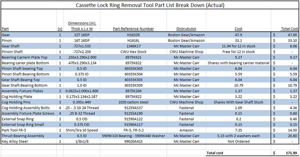
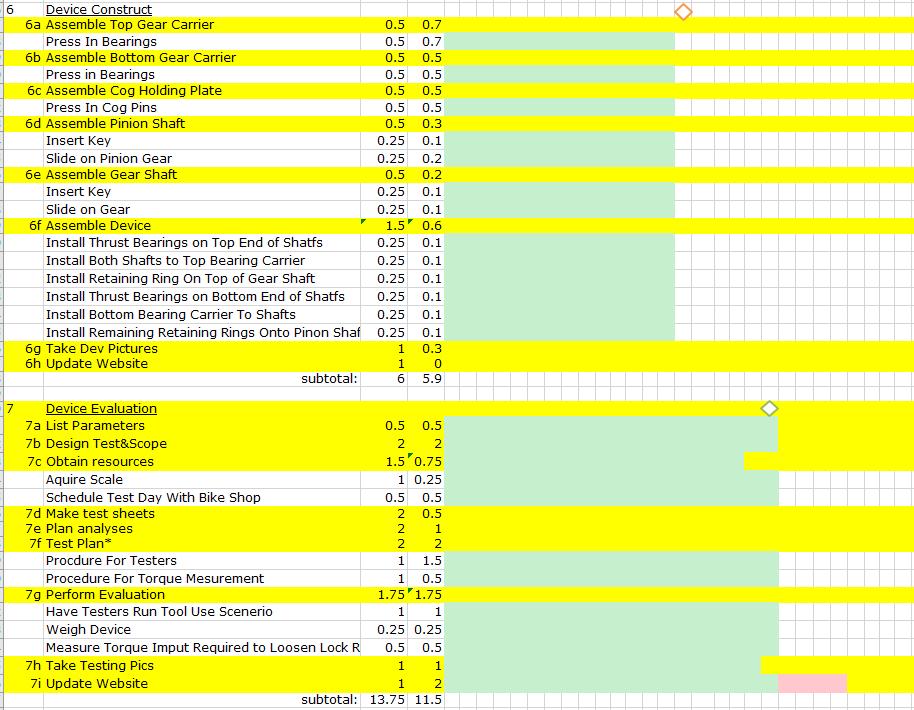
19 Located in Appendix C1.1 is two tables of the following: lists of parts, costs, and distributors along with an overall budget for the project. The first table is of the originally predicted values and the second able is the actual values that the finished project produced. Other costs not associated directly with the parts are labor costs. In this scenario the work done on the project primarily only cost the individual manufacturing the parts their own personal time as none of the work will be contracted to other manufactures. For the purpose of analysis, a labor rate will be associated with the time spent producing and assembling the project. The labor rate will initially be set at 50 dollars per hour assuming that the principle project engineer is also the machinists and has only moderate skills and speed in machining when compared to a professional machinists. The total cost of the project was estimated to be $ before labor and around $2, after labor is included. Again, the labor costs is a theoretical value that won t actually be part of the net costs at project end. Generous time was allowed for the manufacturing tasks in an attempt to overestimate manufacturing costs to avoid going over budget. The completed project total parts cost ended up coming $45.04 under budget. This was accomplished mostly by sourcing small parts in just the quantities needed from different vendors than first planned. For example, the 0.5 OD external snap ring would have cost $9.37 for a minimum order quantity of 100 units through McMaster-Carr. Considering the project only required the use of 2 of these snap rings, the online ordering convenience was not worth the extra cost. Ordering through the local Fastenal only cost $0.40 for the two snap rings instead. Other savings were simply by chance that when at time of ordering, the parts or material were slightly cheaper in some cases. Schedule: Scheduling is based on the time frame of one academic year. This defines the time frame that the project device must be 100% completed by. The year is further broken down into millstones that help set measurable goals for the overall completion of the project. These milestones are separated into three main categories. First, is the completion of the project proposal by the end of fall quarter. This will include the majority of planning, design, and other associated details that will be required to even build the device. The second millstone is the completion of manufacturing and assembly of the device by the end of winter quarter. How well this portion of the project goes will be the deciding factor in how successful the previous quarter was. Lastly, during the spring quarter all testing will be performed on the device to measure how well it meets the initial requirements set during the project initiation. The Schedule can be seen in Appendix D. As of march 2018 the project proposal and device manufacturing is completed. The proposal took 54 hours to compile and was completed on schedule by the first milestone. The device manufacturing and assembly took 47.9 hours during the second milestone segment and was also completed on schedule. Entire project hours totaled to be 143 after completed testing and final report deliverables achieved. This is 20 hours less than the estimated completion time of the project. Project Management: 18
20 This project will have success with the availability and use of experts to provide guidance when issues arise and any complications are met. Project Management: This project will have success with the availability and use of experts to provide guidance when issues arise and any complications are met. Following closely to the schedule to meet deadlines will be essential as well to maintain progress of the project. 6: Discussion During the design phase of the project there were many changes to the ideas and realistic requirements of the device. The basic function of the device remained unchanged but it was the way it would perform the intended task that had multiple alterations. The first area of modification was the type of gears that were planned to be used. Spur gears were the first gears to be used but the size requirements of the gears to handle the subjected loads were much too big. These spur gears had a protruding hub that brought the widths to 1.25 inches wide for a 24 tooth 16 pitch high load metal gear. The overall height of the tool above the top of the cassette is important to reduce the moment created by the user when applying a torque to the input shaft. Helical gears were then chosen because of their high load capabilities and the relative small size of the suitable gears being only 0.50 inches wide. Draw backs of the helical gear choice were the axial thrust force created and the generally higher costs. Thrust washers were a simple solution to the thrust forces and they would also aid in locating the gears in position while taking up little space. One of the requirements for the device was to weigh under 3 pounds. Quickly this was appearing to be very easy to achieve and it was decided to drop the weight requirement for the first attempt of the project as it was not factoring into the decisions of the design. If time allowed for further significant design changes, using bushings in place of bearings would save considerable weight and make the device smaller in size as well. Being able to hold the cassette in place proved to take the most thought and changes in design. At first, there would be an arm with pins that pivots towards the cassette contacting one of the cogs and the pins would interface with the teeth of the cog to hold it in place. This idea presented many problems with accurately getting the arm to contact the intended cog every time along with the forces experienced by the pivot point of the arm. A set of 2 sliding pins that drop in between teeth of one of the cogs seemed a liable option that would have higher strength compared to the arm. This did not work due to not all cassettes having the same sized cogs throughout its gear range. For instance, if the pins were designed to interface with a 17 tooth cog on a cassette, it would only work on cassettes with a 17 tooth cog somewhere in its gear spread. This would render the tool useless on many cassettes. Finally, a design was engineered that utilized the 11 tooth cog on the cassette which is an extremely common size and is also the first cog on top of the entire gear cluster. This set up uses 3 pins that are concentric with the centerline of the gear shaft and are attached to a plate that slides up and down in relation to the device. When the lock ring tool is engaged in the cassette lock ring, the plate can be lowered so the 3 pins will interface in between their own set of teeth on the 11 tooth cog. This design fits the most cassette applications along with providing lots of possible configurations to sustain the applied loads. 19
21 7: Conclusion Loosening a cassette lock ring is a common task in bike shops and home garages around the world. The available tools and methods of performing this task present several problems worthy of engineering design and analysis. A device has been imagined, analyzed, and engineered to accomplish and satisfy the requirements presented to improve upon the current practices in the task. The important analysis that contributed largely to the device success are gear ratio, minimum shaft diameter, and moment created during tool use. These aspects of the design greatly affect the usability and the effort requirements during tool use which are the key aspects of interest when working with hand tools. This senior project meets all requirements for a successful senior project based on: Having sufficient amount of engineering merit in strength of materials, Statics, and Machine Design. The costs and overall size of the project are well within the realm of the available resources. The design is feasible by a manufacturing standpoint. It is directly related to the principal investigators interests and has a useful application. 20
22 The device constructed performed well in regards to the requirements stated initially in the beginning of the project. A summary of these requirements are: Loosen lock ring that is torqued to 30 ft lb o Passed Reduce user torque impute by 50% (15 ft lb) o Passed Smaller than 6 x3 x2 in size o Passed (3.5"x3"x3") Compatible with 3/8 drive tools o Passed Compatible with Shimano style cassette lock rings o Passed Can hang on a tool board in a shop or garage setting o Failed (No Mounting Point) Takes less than 6 seconds to grab tool and perform the task. o Failed (Best Time Was 8 Seconds) 8: Acknowledgments The project would not be possible if not for the guidance, support, and resources provided by many contributors. This includes but is not limited to: MET department staff and professors CWU machine shop and metal/welding shop CWU Technical resources The Recycle Bicycle Shop in downtown Ellensburg for providing device feedback TJ Swartz for welding assistance 10: References All equations and formulas used in analysis are referenced in the analysis sheets. 21

23 9: Appendix A A1.1 - Gear Ratio Calculation 22

24 A1.2 Axial Load Calculation 23

25 A1.3 Radial Force 24

26 A1.4 - Minimum Shaft Diameter 25

27 A1.5 - Minimum Key Length 26

28 A1.6 - Key Seat Depth 27

29 A1.7 - Cog Holding Pin Stress 28

30 A1.8 Gear and Pinon Shaft Stress and Deflection 29

31 A1.9 Moment Created During Device Use 30

32 A1.10 Cog Holding Plate Locating Bolts Shear Stress 31

33 A1.11 Potential Lever Arm Deflection 32

34 A1.12 Shear Stress on Assembly Plate Screws 33
35 10: Appendix B Drawings Cassette Lock Ring Removal Tool Assembly Top Gear Carrier Assembly Bottom Bearing Carrier Assembly Top Bearing Carrier Bearings Bottom Bearing Carrier Bearings Shoulder Screws Cog Holding Plate Assembly Cog Holding Plate Cog Holding Pins Gear Shaft Assembly Pinon Shaft Assembly Fixing Plate Assembly Gear Shaft Gear Pinon Shaft Pinon Gear Fixing Plate Screws Key External Snap Ring Key External Snap Ring Thrust Bearings Cassette Tool Thrust Bearings 34

36 B1.1 Top Bearing Carrier 35

37 B1.2 Gear Shaft V-2 36

38 B1.3 - Pinon Shaft V2 37

39 B1.4 Bearing Carrier Fixing Plate 38

40 B1.5 Bottom Bearing Carrier 39

41 B1.6 Cassette Tool Modified 40

42 B1.7 Cog Holding Plate 41

43 B1.8 Pin for 11 Tooth Sprocket Holder 42

44 B1.9 Cassette Lock Ring Removal Tool Assembly 43
45 B1.10 Exploded Assembly Drawing 44

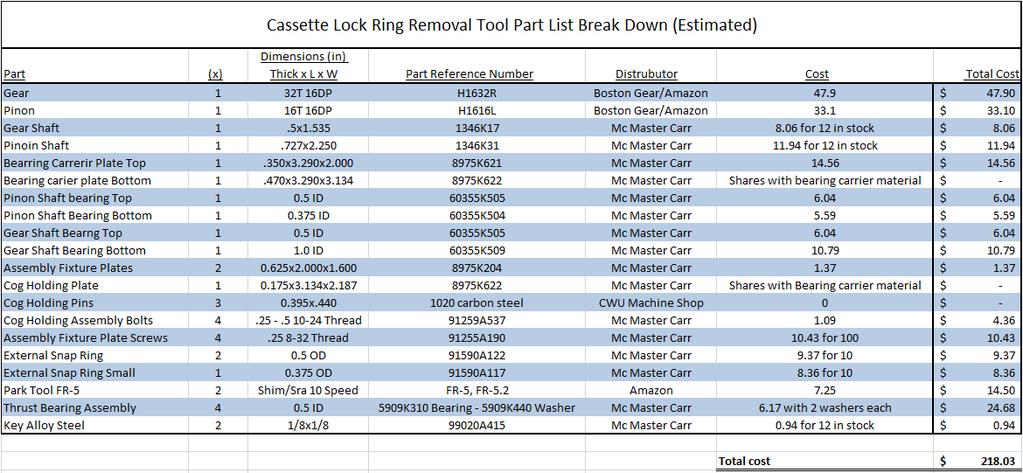
46 C1.1 Project Budget/Parts List 11: Appendix C
47 46

48 Project Schedule 12: Appendix D

49 48

50 49

51 Testing Data 13: Appendix E Comparison of Device to Traditional Methods Overview This test will be used to evaluate the effectiveness of the device against the traditional method of cassette lock ring removal in a regular bicycle shop setting. The task is to remove the lockring on a bicycle cassette. Time to perform the task will be recorded for each method with multiple trials to establish consistent results. Time, Duration The test is to take 5-10 minutes per tester and around 30 minutes to complete testing with every tester if 3 testers are used. Location The tests will be performed at The Recycle Shop bicycle shop in Ellensburg, WA. Resources Needed A testing surface such as a table or work bench, stop watch, tools (torque wrench, chain whip, lockring tool, wrench, cassette lockring removal device), wheel with a mounted cassette with a smallest cog of 11 teeth. Chain Lockring 50
. 2.")
 With the wheel on the work surface, place the chain whip on the cassette so the chain whip will hold the cassette stationary when attempting to rotate the cassette in the counter clockwise")
52 Cassette Lockring Test Procedure Steps: 1. Set up a work station with the proper tools for traditional cassette removal (Cassette mounted to a wheel and torqued to 30 ft-lb, chain whip, cassette tool, wrench, and work bench or table space). 2. With safety glasses and gloves if desired, have tester perform the task a few times as described in 2. a-d, to become familiar with the tools and test environment setup. a) With the wheel on the work surface, place the chain whip on the cassette so the chain whip will hold the cassette stationary when attempting to rotate the cassette in the counter clockwise direction. See Image Below. b) Index the lockring tool into the cassette lockring. c) While holding the chain whip, place a wrench on the lockring tool and turn the cassette tool in the counter clockwise direction to loosen the lockring. d) Continue loosening the lockring until it can be completely removed from the cassette. Chain Whip and Lockring Tool 3. Re-torque the lockring prior to the start of the test to 30 ft-lb 4. With the tools arranged in an organized layout that can be reproduced after each test, begin the test by timing the tester from start to finish how long it takes to loosen and remove the cassette lockring, stopping the time when the lockring is completely removed from the cassette. Record the time. 5. Repeat steps 3 and 4 a minimum of three times for each tester. 6. Set up a work station as described in step 1 but with the cassette lockring removal device instead of the chain whip and cassette tool. 51

53 7. Have the tester perform the task again for practice but this time by indexing the cassette lockring tool into the cassette lockring and then the pins of the tool in-between the teeth of the top cog of the cassette. After the tool is indexed properly on the cassette use the wrench to turn the protruding shaft in the clockwise direction to loosen and remove the lockring while holding the wheel stable with the other hand. 8. Perform steps 3 through After all testing is complete, have the tester give feedback about how both methods compare and what they do and do not like about each method. Safety The test is in a safe environment with only minor safety equipment required such as eye protection and optional gloves. Discussion Variables such as work surface height, actual available work space, and different wrench configurations will have an effect on the effort and ergonomics of performing the lockring removal task. Timed Test Results/Data 52
54 14: Appendix F KYLE WRIGHT (253) kylegwright@comcast.net 108 E 18th Ave Ellensburg, WA VALUE As a current student in the field of mechanical engineering and a history of mechanical jobs and interests, I have a combination of practical experience and the ability to be critical of the engineering principles at hand when working with machines and systems. This has taught me how to process complex problems and implement appropriate solutions. WORK EXPERIENCE Webb Powersports Ellensburg, WA Nov Current Mechanic Promoted to shop suspension specialist Assemble and perform final inspections of sold machines Successfully diagnose and repair problems on machines The Recycle Shop Ellensburg, WA Nov Dec 2016 Bicycle Mechanic/Sales Promoted to more difficult jobs and given a key to the shop before other co-workers Informed customers about performance differences between component groups among multiple bicycles at different price points. Diagnosed and determined proper repairs/modifications based on budget and timeframe. Lynden Transportation Seattle, WA Mar Sep 2014 Lasher/Bander Became the fastest and most consistent bander on my shift as a team with my co-worker Worked around heavy machinery while being aware of my surroundings Was on time everyday working five 10 hour shifts a week for entirety of employment SKILLS Experience in Solid Works, CNC Programming, Machining, and Welding/Fabrication Competent With Microsoft Word and Excel Mechanically Inclined Breadth of Experience from Customer Service to Hard Manual Labor Organized EDUCATION Central Washington University Ellensburg, WA Sep Jun 2018 Mechanical Engineering Technologies Pierce College Puyallup, WA Sep Mar 2014 Pre-Engineering Clover Park Technical College Lakewood, WA Sep Aug
55 Studied Non-Destructive Testing VOLUNTEERING/ACTIVITIES CWU Cycling President 2015/2016 Season Soccer Tots Volunteer Coach Mountain Biking Dirt Biking 54
Stationary Bike Generator System (Drive Train)
") Central Washington University ScholarWorks@CWU All Undergraduate Projects Undergraduate Student Projects Summer 2017 Stationary Bike Generator System (Drive Train) Abdullah Adel Alsuhaim cwu, 280zxf150@gmail.com
Central Washington University ScholarWorks@CWU All Undergraduate Projects Undergraduate Student Projects Summer 2017 Stationary Bike Generator System (Drive Train) Abdullah Adel Alsuhaim cwu, 280zxf150@gmail.com
Stationary Bike Generator System
 Central Washington University ScholarWorks@CWU All Undergraduate Projects Undergraduate Student Projects Spring 2017 Stationary Bike Generator System Rakan Alghamdi Central Washington University, rk_rk11@hotmail.com
Orbital Test Stand. By Mary Begay, Brett Booen, Calvin Boothe, James Ellis and Nicholas Garcia. Team 7. Project Proposal Document
 Orbital Test Stand By Mary Begay, Brett Booen, Calvin Boothe, James Ellis and Nicholas Garcia Team 7 Project Proposal Document Submitted towards partial fulfillment of the requirements for Mechanical Engineering
Pin Router Duplicator Base
 Central Washington University ScholarWorks@CWU All Undergraduate Projects Undergraduate Student Projects Spring 2017 Pin Router Duplicator Base Matthew Tebo tebom@cwu.edu Follow this and additional works
External Hard Drive: A DFMA Redesign
 University of New Mexico External Hard Drive: A DFMA Redesign ME586: Design for Manufacturability Solomon Ezeiruaku 4-23-2013 1 EXECUTIVE SUMMARY The following document serves to illustrate the effects
SAE Mini BAJA: Suspension and Steering
 SAE Mini BAJA: Suspension and Steering By Zane Cross, Kyle Egan, Nick Garry, Trevor Hochhaus Team 11 Progress Report Submitted towards partial fulfillment of the requirements for Mechanical Engineering
Hydraulic Sprayer Boom Upgrade
 Central Washington University ScholarWorks@CWU All Undergraduate Projects Undergraduate Student Projects Spring 2016 Hydraulic Sprayer Boom Upgrade Chad R. Omlin Central Washington University, chadomlin@gmail.com
SAE Baja - Drivetrain
 SAE Baja - Drivetrain By Ricardo Inzunza, Brandon Janca, Ryan Worden Team 11A Concept Generation and Selection Document Submitted towards partial fulfillment of the requirements for Mechanical Engineering
MET 314 Torque Measurement
 Central Washington University ScholarWorks@CWU All Undergraduate Projects Undergraduate Student Projects Spring 2016 MET 314 Torque Measurement Jose Bejar Central Washington University, bejarj@cwu.edu
"Top Ten" reasons to measure: 10. To Provide Proper Sheet Metal Fit
 Important Reasons why your collision shop needs to Measure. This is one of the most important functions of collision repair and it is a Must Do Process for the success of your business. by Tom Brandt Whether
INME 4011 Term Project Guideline
 INME 4011 Term Project Guideline Each team consists of four students (maximum). The projects are described in the attached document. First part of the project includes the calculation of the shaft diameter
Mechanical Considerations for Servo Motor and Gearhead Sizing
 PDHonline Course M298 (3 PDH) Mechanical Considerations for Servo Motor and Gearhead Sizing Instructor: Chad A. Thompson, P.E. 2012 PDH Online PDH Center 5272 Meadow Estates Drive Fairfax, VA 22030-6658
Folding Shopping Cart Design Report
 Folding Shopping Cart Design Report EDSGN 100 Section 010, Team #4 Submission Date- 10/28/2013 Group Image with Prototype Submitted by: Arafat Hossain, Mack Burgess, Jake Covell, and Connor Pechko (in
Project Report Cover Page
 New York State Pollution Prevention Institute R&D Program 2015-2016 Student Competition Project Report Cover Page University/College Name Team Name Team Member Names SUNY Buffalo UB-Engineers for a Sustainable
High Accessibility Cabinet Insert
 Central Washington University ScholarWorks@CWU All Undergraduate Projects Undergraduate Student Projects Summer 2017 High Accessibility Cabinet Insert Matthew Leal Central Washington University, lealm@cwu.edu
LESSON Transmission of Power Introduction
 LESSON 3 3.0 Transmission of Power 3.0.1 Introduction Earlier in our previous course units in Agricultural and Biosystems Engineering, we introduced ourselves to the concept of support and process systems
Steeda Sport Mustang Lowering Springs (2005+) - Installation Instructions
 - Installation Instructions") Steeda Sport Mustang Lowering Springs (2005+) - Installation Instructions The below installation instructions work for the following products: Steeda Sport Mustang Lowering Springs (2005+) Please read
Steeda Sport Mustang Lowering Springs (2005+) - Installation Instructions The below installation instructions work for the following products: Steeda Sport Mustang Lowering Springs (2005+) Please read
PRESEASON CHASSIS SETUP TIPS
 PRESEASON CHASSIS SETUP TIPS A Setup To-Do List to Get You Started By Bob Bolles, Circle Track Magazine When we recently set up our Project Modified for our first race, we followed a simple list of to-do
LEAD SCREWS 101 A BASIC GUIDE TO IMPLEMENTING A LEAD SCREW ASSEMBLY FOR ANY DESIGN
 LEAD SCREWS 101 A BASIC GUIDE TO IMPLEMENTING A LEAD SCREW ASSEMBLY FOR ANY DESIGN Released by: Keith Knight Kerk Products Division Haydon Kerk Motion Solutions Lead Screws 101: A Basic Guide to Implementing
Progress Report. Maseeh College of Engineering & Computer Science Winter Kart 2. Design Team Atom Falcone Austin Greene. Nick Vanklompenberg
 Progress Report Maseeh College of Engineering & Computer Science Winter 2016 Kart 2 Design Team Atom Falcone Austin Greene Jesse Majoros Nick Vanklompenberg Jake Waterman Jeffrey Williamson Faculty Advisor
J&M Mustang Adjustable Panhard Rod (05-09) - Installation Instructions
 - Installation Instructions") J&M Mustang Adjustable Panhard Rod (05-09) - Installation Instructions The below installation instructions work for the following products: J&M Mustang Adjustable Panhard Rod (05-09) Please read through
J&M Mustang Adjustable Panhard Rod (05-09) - Installation Instructions The below installation instructions work for the following products: J&M Mustang Adjustable Panhard Rod (05-09) Please read through
SHAFT ALIGNMENT FORWARD
 Service Application Manual SAM Chapter 630-76 Section 24 SHAFT ALIGNMENT FORWARD One of the basic problems of any installation is aligning couplings or shafts. Therefore, this section will endeavor to
Moments. It doesn t fall because of the presence of a counter balance weight on the right-hand side. The boom is therefore balanced.
 Moments The crane in the image below looks unstable, as though it should topple over. There appears to be too much of the boom on the left-hand side of the tower. It doesn t fall because of the presence
Applications in Design & Engine. Analyzing Compound, Robotic Machines
 v2.1 Compound Machines ering Applications in Design & Engine Analyzing Compound, Robotic Machines Educational Objectives At the conclusion of this lesson, students should be able to: Understand the relationship
CHAPTER 6 GEARS CHAPTER LEARNING OBJECTIVES
 CHAPTER 6 GEARS CHAPTER LEARNING OBJECTIVES Upon completion of this chapter, you should be able to do the following: Compare the types of gears and their advantages. Did you ever take a clock apart to
Remote Control Helicopter. Engineering Analysis Document
 Remote Control Helicopter By Abdul Aldulaimi, Travis Cole, David Cosio, Matt Finch, Jacob Ruechel, Randy Van Dusen Team 04 Engineering Analysis Document Submitted towards partial fulfillment of the requirements
Introduction: Problem statement
 Introduction: Problem statement The goal of this project is to develop a catapult system that can be used to throw a squash ball the farthest distance and to be able to have some degree of accuracy with
Development of Relief Valve Automatic assembly technology
 Development of Relief Valve Automatic assembly technology Technology Explanation Development of Relief Valve Automatic assembly technology TAKIGUCHI Masaki Abstract Construction machinery is equipped with
SAE Mini BAJA: Suspension and Steering
 SAE Mini BAJA: Suspension and Steering By Zane Cross, Kyle Egan, Nick Garry, Trevor Hochhaus Team 11 Project Progress Submitted towards partial fulfillment of the requirements for Mechanical Engineering
ASME Human Powered Vehicle
 ASME Human Powered Vehicle By Yousef Alanzi, Evan Bunce, Cody Chenoweth, Haley Flenner, Brent Ives, and Connor Newcomer Team 14 Mid-Point Review Document Submitted towards partial fulfillment of the requirements
TrueGyde Microcoil. Author: Marcel Berard Co-Author: Philippe Berard
 Author: Marcel Berard Co-Author: Philippe Berard Introduction TrueGyde Steer supports the microcoil as an alternate magnetic source to the standard coil. This document describes how to build and use a
Layout Analysis using Discrete Event Simulation: A Case Study
 Proceedings of the 2010 Industrial Engineering Research Conference A. Johnson and J. Miller, eds. Layout Analysis using Discrete Event Simulation: A Case Study Abstract ID: 439 Robbie Holt, Lucas Simmons,
MECHANISMS. AUTHORS: Santiago Camblor y Pablo Rivas INDEX
 MECHANISMS AUTHORS: Santiago Camblor y Pablo Rivas INDEX 1 INTRODUCTION 2 LEVER 3 PULLEYS 4 BELT AND PULLEY SYSTEM 5 GEARS 6 GEARS WITH CHAIN 7 WORM GEAR 8 RACK AND PINION 9 SCREW AND NUT 10 CAM 11 ECCENTRIC
Bearings. Rolling-contact Bearings
 Bearings A bearing is a mechanical element that limits relative motion to only the desired motion and at the same time it reduces the frictional resistance to the desired motion. Depending on the design
How to Build with the Mindstorm Kit
 How to Build with the Mindstorm Kit There are many resources available Constructopedias Example Robots YouTube Etc. The best way to learn, is to do Remember rule #1: don't be afraid to fail New Rule: don't
Specifications. Trantorque GT CALL FAX
 GT Specifications The following pages contain engineering data and product specifications for GT. For CAD drawings of GT, please click on the part number to download the drawing. All drawings are in AutoCAD
RC Baja Car Suspension
 Central Washington University ScholarWorks@CWU All Undergraduate Projects Undergraduate Student Projects Spring 2018 RC Baja Car Suspension Tyler Martin Central Washington University, tylermartintjm@gmail.com
Timing the 9N/2N Steering Sector Gears
 Timing the 9N/2N Steering Sector Gears by John Korschot - www.johnsoldiron.com (May 2010) The procedure for timing a set of steering gears in the 9/2n tractors is published in the I&T FO4 shop manual.
Battery Technology for Data Centers and Network Rooms: Site Planning
 Battery Technology for Data Centers and Network Rooms: Site Planning White Paper # 33 Executive Summary The site requirements and costs for protecting information technology and network environments are
Mechanical Power Transmission. September 16, 2008
 2008 TE Sessions Supported by Mechanical Power Transmission September 16, 2008 www.robojackets.org Goals Hand out kits to teams that don t have one. More physics concepts and terms Understanding key devices
TRANSLATION (OR LINEAR)
") 5) Load Bearing Mechanisms Load bearing mechanisms are the structural backbone of any linear / rotary motion system, and are a critical consideration. This section will introduce most of the more common
5) Load Bearing Mechanisms Load bearing mechanisms are the structural backbone of any linear / rotary motion system, and are a critical consideration. This section will introduce most of the more common
Smart Spinner. Age 7+ Teacher s Notes. In collaboration with NASA
 Smart Spinner Age 7+ Teacher s Notes In collaboration with NASA LEGO and the LEGO logo are trademarks of the/sont des marques de commerce de/son marcas registradas de LEGO Group. 2012 The LEGO Group. 190912
2012 Baja SAE Drivetrain
 2012 Baja SAE Drivetrain A thesis submitted to the Faculty of the Mechanical Engineering Technology Program of the University of Cincinnati in partial fulfillment of the requirements for the degree of
Maintenance Safety. Jim Seay, ICAE Chairman, IAAPA Global Safety Committee President, Premier Rides Immediate Past Chair, ASTM F24
 Maintenance Safety Jim Seay, ICAE Chairman, IAAPA Global Safety Committee President, Premier Rides Immediate Past Chair, ASTM F24 August 30, 2016 Welcome Back! Overview Industry Growth in Asia Challenges
The H-MAC Heavy Metal Articulating Chassis Construction Guide
 The H-MAC Heavy Metal Articulating Chassis Construction Guide The Heavy Metal Chassis is constructed with two identical drive modules built using 10 mechanical sub-assemblies. The drive modules are integrated
Conoco Phillips Ferndale Condition Monitoring Success
 Conoco Phillips Ferndale Condition Monitoring Success From Chaos to Calm with Azima DLI Methodology Background The Conoco Phillips Ferndale Washington Refinery was constructed in 1954. Ferndale is an integrated
Chapter 11. Keys, Couplings and Seals. Keys. Parallel Keys
 Chapter 11 Keys, Couplings and Seals Material taken for Keys A key is a machinery component that provides a torque transmitting link between two power-transmitting elements. The most common types of keys
MECHANICAL SYSTEMS - Reference Page
 ANSWER KEY Student Class MECHANICAL SYSTEMS - Reference Page Refer to the following Formulas that you may need to use throughout this exam Science I n Action 8 Mechanical Systems UNIT Test Numerical Response
Increase Factor of Safety of Go-Kart Chassis during Front Impact Analysis
 IJIRST International Journal for Innovative Research in Science & Technology Volume 3 Issue 04 September 2016 ISSN (online): 2349-6010 Increase Factor of Safety of Go-Kart Chassis during Front Impact Analysis
Washington, DC U.S.A. SC-M150-00X Axial Flux, Permanent Magnet, DC Brushless Electric Motor Operating Manual Version 1.00
 Washington, DC U.S.A. SC-M150-00X Axial Flux, Permanent Magnet, DC Brushless Electric Motor Operating Manual Version 1.00 1 TABLE OF CONTENTS 1. SC-M150 MOTOR SERIES...3 2. ELECTRICAL CONNECTIONS...3 2.1
Marine Engineering Exam Resource Review of Couplings
 1. What are rigid couplings used for? Used to join drive shafts together. True alignment and rigidity are required. Example Drive shafts and production lines, bridge cranes, solid shaft that needs to be
M3 Design Product Teardown Kobalt Double-Drive Screwdriver
 19 Jun, 2013 Why do the product teardowns? M3 Design Product Teardown Kobalt Double-Drive Screwdriver Part of the product development process is to apply knowledge gained from prior experience during the
Learning to Set-Up Your Warrior Drive Belt Arizona Warrior (Rev4) BEFORE GETTING STARTED
 BEFORE GETTING STARTED") BEFORE GETTING STARTED 1. A noise one guy calls 'howling' is the same noise another guy calls 'squealing' so unless you are both hearing the noise with your own ears its better to not assume a drive belt
BEFORE GETTING STARTED 1. A noise one guy calls 'howling' is the same noise another guy calls 'squealing' so unless you are both hearing the noise with your own ears its better to not assume a drive belt
VEX ELECTROMAGNET. Make It Real CAD Engineering Challenge
 VEX ELECTROMAGNET Make It Real CAD Engineering Challenge CONTENT Introduction... 2 Description... 2 Components Description... 3 Technical Specifications... 4 Force exerted by magnetic field... 5 how the
Connor Needham Roger Williams University Bristol, RI, United States. Jeremy Kacher Roger Williams University Bristol, RI, United States
 ASEE 2014 Zone I Conference, April 3-5, 2014, University of Bridgeport, Bridgpeort, CT, USA. Design of a Vertical Axis Wind Turbine for Urban Areas Hidden In Plain Sight Wind Energy Conservation System
Model 320 / 320A Hinge Assembly
 MANUFACTURING CO. THE FIRST NAME IN QUALITY COUPLINGS Installation, Inspection, Operation & Maintenance Guide Model 320 / 320A Hinge Assembly IMPORTANT Read these instructions completely before installing,
 DRUM BRAKE RIMS Periodic inspection of drum brake rims is necessary to determine indications of uneven or excessive wear. In general, brake rim failures other that regular wear are caused by brake linings
Agricultural Track Service Procedures Removal, Installation, Inspection and Alignment
 Agricultural Track Service Procedures Removal, Installation, Inspection and Alignment CNH STX Quadtrac Series CPB-0303 8/1/2006 Table of Contents Introduction...1 Track Terminology...1 General Tooling
OVERSIZED DERAILLEUR PULLEY EFFICIENCY TEST
 OVERSIZED DERAILLEUR PULLEY EFFICIENCY TEST SUMMARY 0.49 watts efficiency difference was measured between a 10T-10T pulley combination and a 15T-15T pulley combination, with chain tension and bearing variables
Factors Influencing the Performance of Ball and Rolling Bearings
 Factors Influencing the Performance of Ball and Rolling Bearings Course No: M02-033 Credit: 2 PDH Robert P. Tata, P.E. Continuing Education and Development, Inc. 9 Greyridge Farm Court Stony Point, NY
Chapter 7: DC Motors and Transmissions. 7.1: Basic Definitions and Concepts
 Chapter 7: DC Motors and Transmissions Electric motors are one of the most common types of actuators found in robotics. Using them effectively will allow your robot to take action based on the direction
Chapter 7. Shafts and Shaft Components
 Chapter 7 Shafts and Shaft Components 2 Chapter Outline Introduction Shaft Materials Shaft Layout Shaft Design for Stress Deflection Considerations Critical Speeds for Shafts Miscellaneous Shaft Components
All levers are one of three types, usually called classes. The class of a lever depends on the relative position of the load, effort and fulcrum:
 Página 66 de 232 Mechanisms A mechanism is simply a device which takes an input motion and force, and outputs a different motion and force. The point of a mechanism is to make the job easier to do. The
Timing Belt Selection Using Visual Basic
 3225 Timing Belt Selection Using Visual Basic Edward M. Vavrek Purdue University North Central Abstract Timing belts are used in many different machine applications. The sizing and selection of an appropriate
ASME RC Baja Car: Suspension and Chassis
 Central Washington University ScholarWorks@CWU All Undergraduate Projects Undergraduate Student Projects Spring 2017 ASME RC Baja Car: Suspension and Chassis C. Aidan Pringle Central Washington University,
Delivery System for Hernia Mesh Fixation
 Delivery System for Hernia Mesh Fixation Design Team Joseph Aaron, Andrew Edgerly Charles O Connell, Charles Sidoti, David Stone Design Advisor Dr. Jeffrey Ruberti Sponsor High Road Medical Abstract The
25460/25465/25485/ Toyota Adjustable Upper Control Arms
 25460/25465/25485/25490 Toyota Adjustable Upper Control Arms Q1: I have the new SpecRide bushings. Why is my front suspension squeaking? A1: If you used the INCLUDED grease packet, and greased both the
MODELING SUSPENSION DAMPER MODULES USING LS-DYNA
 MODELING SUSPENSION DAMPER MODULES USING LS-DYNA Jason J. Tao Delphi Automotive Systems Energy & Chassis Systems Division 435 Cincinnati Street Dayton, OH 4548 Telephone: (937) 455-6298 E-mail: Jason.J.Tao@Delphiauto.com
25455/25470/ Toyota Adjustable Upper Control Arms
 Toyota Adjustable Upper Control Arms Q1: I have a lift kit; will the control arms handle the increased angle? A1: These control arms have approximately 20 more articulation capability than your OEM arms
Kaydon white paper. The importance of properly mounting thin section bearings. an SKF Group brand. by Rob Roos, Senior Product Engineer
 The importance of properly mounting thin section by Rob Roos, Senior Product Engineer an SKF Group brand Figure 1 Radial Load Reversing Thrust Overturning Moment Thin section ball have a much thinner cross-section
PROJECT IDEA SUBMISSION
 PROJECT IDEA SUBMISSION Team Contacts - 1 st person listed serves as the point of contact with Professor Nelson - Initial team size may be from 1 to 6 members (all members must agree to have their name
Design And Fabrication Of An Incense Stick Making Machine
 Design And Fabrication Of An Incense Stick Making Machine Madhur Bakhle, Shivani Gite, Ameya Poyarekar, Ayaz Siddiqui, Shradha Patil Abstract: The design and fabrication of a low cost pedal operated incense-stick
Bicycles in Zambia: A study in two design approaches. Authors: Dan Janosec, Bala Radharamanan, Tony Ricciardi
 Bicycles in Zambia: A study in two design approaches Authors: Dan Janosec, Bala Radharamanan, Tony Ricciardi Design Brief As it currently stands, most farmers in Zambia utilize hand tools in order to complete
Installation and Operation Manual. Manufacturers of Innovative Materials Handling Equipment since 1957.
 SWINGSET DISTRIBUTOR Installation and Operation Manual Manufacturers of Innovative Materials Handling Equipment since 1957. 491 North Emerson Street * Cambridge MN 55008-1316 U.S.A. Toll Free (800) 328-8002
Racing Tires in Formula SAE Suspension Development
 The University of Western Ontario Department of Mechanical and Materials Engineering MME419 Mechanical Engineering Project MME499 Mechanical Engineering Design (Industrial) Racing Tires in Formula SAE
Sheet 1 Variable loading
 Sheet 1 Variable loading 1. Estimate S e for the following materials: a. AISI 1020 CD steel. b. AISI 1080 HR steel. c. 2024 T3 aluminum. d. AISI 4340 steel heat-treated to a tensile strength of 1700 MPa.
Evaluation of Vibrostrengthening for Fatigue Enhancement of Titanium Structural Components on Commercial Aircraft
 Evaluation of Vibrostrengthening for Fatigue Enhancement of Titanium Structural Components on Commercial Aircraft D. H. Gane 1, Y. S. Rumyantsev 2, H. T. Diep 1, L. Bakow 1 1 Boeing Commercial Aircraft
Reverse Engineering case-study application in Motorsport. TITLE: Ergonomical study for the development of a new brake arm in motorbike
 Reverse Engineering case-study application in Motorsport TITLE: Ergonomical study for the development of a new brake arm in motorbike ABSTRACT The braking line represents in the world of motorcycle competition
Installation Manual TWM Performance Short Shifter Cobalt SS/SC, SS/TC, HHR SS, Ion Redline and Saab 9-3
 Page 1 Installation Manual TWM Performance Short Shifter Cobalt SS/SC, SS/TC, HHR SS, Ion Redline and Saab 9-3 Please Note: It is preferable to park on a flat surface, as you will have to engage and disengage
DESIGN OF MACHINE ELEMENTS UNIVERSITY QUESTION BANK WITH ANSWERS. Unit 1 STEADY STRESSES AND VARIABLE STRESSES IN MACHINE MEMBERS
 DESIGN OF MACHINE ELEMENTS UNIVERSITY QUESTION BANK WITH ANSWERS Unit 1 STEADY STRESSES AND VARIABLE STRESSES IN MACHINE MEMBERS 1.Define factor of safety. Factor of safety (FOS) is defined as the ratio
SHAFT ALIGNMENT: Where do I start, and what is the benefit?
 SHAFT ALIGNMENT: Where do I start, and what is the benefit? Why precision alignment? Reduce your energy consumption Fewer failures of seals, couplings and bearings Lower temperatures of bearings and coupling
F.I.R.S.T. Robotic Drive Base
 F.I.R.S.T. Robotic Drive Base Design Team Shane Lentini, Jose Orozco, Henry Sick, Rich Phelan Design Advisor Prof. Sinan Muftu Abstract F.I.R.S.T. is an organization dedicated to inspiring and teaching
Stress Analysis in Pulley of Stacker-Reclaimer by Using Fem Vs Analytical
 Stress Analysis in Pulley of Stacker-Reclaimer by Using Fem Vs Analytical X. Oscar fenn Daniel 1, A. Hussain lal 2 PG. Scholar, Department of Mechanical Engineering,, JJ College of Engineering and Technology,
Assemblies for Parallel Kinematics. Frank Dürschmied. INA reprint from Werkstatt und Betrieb Vol. No. 5, May 1999 Carl Hanser Verlag, München
 Assemblies for Parallel Kinematics Frank Dürschmied INA reprint from Werkstatt und Betrieb Vol. No. 5, May 1999 Carl Hanser Verlag, München Assemblies for Parallel Kinematics Frank Dürschmied Joints and
Engineering Fundamentals Final Project Engineering Lab Report
 Engineering Fundamentals Final Project Engineering Lab Report 4/26/09 Tony Carr Christopher Goggans Zach Maxey Matt Rhule Team Section A2-6 Engineering Fundamentals 151 I have read and approved of the
Simple Gears and Transmission
 Simple Gears and Transmission Simple Gears and Transmission page: of 4 How can transmissions be designed so that they provide the force, speed and direction required and how efficient will the design be?
The Available Solution CYCLO DRIVE. Gearmotors & Speed Reducers. Series
 The Available Solution CYCLO DRIVE Gearmotors & Speed Reducers 6000 Series WHAT DO YOU THINK OF THIS? THESE ARE THE ADVANTAGES OF THE NEWEST CYCLO, 6000 SERIES: More frame sizes, gear ratios and motor
RV-7 / RV-8 / RV-10 Installation Kit Trio Gold Standard Roll Servo
 RV-7 / RV-8 / RV-10 Installation Kit Trio Gold Standard Roll Servo Thank you for purchasing the Trio Avionics Servo Installation Kit. This guide provides a general overview for installation of the Trio
How to: Test & Evaluate Motors in Your Application
 How to: Test & Evaluate Motors in Your Application Table of Contents 1 INTRODUCTION... 1 2 UNDERSTANDING THE APPLICATION INPUT... 1 2.1 Input Power... 2 2.2 Load & Speed... 3 2.2.1 Starting Torque... 3
How to Achieve a Successful Molded Gear Transmission
 How to Achieve a Successful Molded Gear Transmission Rod Kleiss Figure 1 A molding insert tool alongside the molded gear and the gear cavitiy. Molded plastic gears have very little in common with machined
A Cost Benefit Analysis of Faster Transmission System Protection Schemes and Ground Grid Design
 A Cost Benefit Analysis of Faster Transmission System Protection Schemes and Ground Grid Design Presented at the 2018 Transmission and Substation Design and Operation Symposium Revision presented at the
Edwards Engineering Corporation
 SUGAR MILL DRIVE CONSIDERATIONS One of the most important tasks of a sugar factory manager is deciding on how best to invest limited resources on capital expenditures such as sugar mill drives. In an attempt
SAE Baja - Drivetrain
 SAE Baja - Drivetrain By Ricardo Inzunza, Brandon Janca, Ryan Worden Team 11 Engineering Analysis Document Submitted towards partial fulfillment of the requirements for Mechanical Engineering Design I
Shifting gears: simplify your design with slewing ring bearings
 White Paper Shifting gears: simplify your design with slewing ring bearings Scott Hansen, VP, Manufacturing Planning, Kaydon Bearings, an SKF Group company A slewing ring bearing has rolling elements designed
Thanks for Ordering The Kawasaki KLX Adjustable Lowering Kit From
 www.scootworks.com Thanks for Ordering The Kawasaki KLX Adjustable Lowering Kit From READ THIS BEFORE UNPACKING YOUR KIT! This instruction booklet contains detailed steps for installing the rear suspension
2020 Proposal Plan: Battery Drop Off Recycling. A Proposal Plan for ENVL 4300 Professor: Tait Chirenje
 2020 Proposal Plan: Battery Drop Off Recycling A Proposal Plan for ENVL 4300 Professor: Tait Chirenje Matt Cole, Andrew Lindsay, Tim Pagan Environmental Issues: ENVL 4300 Stockton University April 28,
The Pneumatic Leg Extension
 Central Washington University ScholarWorks@CWU All Undergraduate Projects Undergraduate Student Projects Spring 2016 The Pneumatic Leg Extension David G. Sedano Central Washington University, sedanod@cwu.edu
Technical Math 2 Lab 3: Garage Door Spring 2018
 Name: Name: Name: Name: As you may have determined the problem is a broken spring (clearly shown on the left in the picture below) which needs to be replaced. I. Garage Door Basics: Common residential
Linear Induction Motor (LIMO) Modular Test Bed for Various Applications
 Modular Test Bed for Various Applications") Linear Induction Motor (LIMO) Modular Test Bed for Various Applications ECE 4901 Senior Design I Fall 2013 Fall Project Report Team 190 Members: David Hackney Jonathan Rarey Julio Yela Faculty Advisor
Linear Induction Motor (LIMO) Modular Test Bed for Various Applications ECE 4901 Senior Design I Fall 2013 Fall Project Report Team 190 Members: David Hackney Jonathan Rarey Julio Yela Faculty Advisor
Electromagnetic Fully Flexible Valve Actuator
 Electromagnetic Fully Flexible Valve Actuator A traditional cam drive train, shown in Figure 1, acts on the valve stems to open and close the valves. As the crankshaft drives the camshaft through gears