OVERSIZED DERAILLEUR PULLEY EFFICIENCY TEST
|
|
|
- Gordon Jesse Dawson
- 5 years ago
- Views:
Transcription
1 OVERSIZED DERAILLEUR PULLEY EFFICIENCY TEST

2 SUMMARY 0.49 watts efficiency difference was measured between a 10T-10T pulley combination and a 15T-15T pulley combination, with chain tension and bearing variables held constant. This data positively confirms the general theory of decreased friction with increased pulley diameter, with all other variables excluded. With cage tension and bearing variables introduced, a 1.76 watt efficiency difference was measured between the best and worst performing derailleur systems (a system includes the manufacturer s cage, pulleys, and bearings within the pulleys), namely the Berner 13T-15T pulley/cage combination being the most efficient and the Dura Ace 11T-11T pulley/cage combination being least efficient. Graph 1: Frictional Losses in watts of each pulley combination for Parts 1, 2, and 3.
 vs.")
3 RESULTS Part 1: Generic plastic pulley wheels tested to validate the theory. Chain tension held constant at 2.4lb per span. Bearings held constant. The same two ceramic bearings were used for each of the eight pulley combinations. Plastic 10T, 11T, 13T, and 15T wheels used for Part 1. Graph 2: Frictional Losses (watts) vs. Pulley Size Combination. Chain tension and bearings held constant.

4 Graph 3: Frictional Losses (watts) vs Total Chain Articulation Angle. A linear trend line was superimposed. Chain tension and bearings held constant. Total Chain Articulation Angle is the sum of the engagement and disengagement angles for both upper and lower pulleys. For example, a 10T-10T combination is 36 engagement plus 36 disengagement times two 10T pulleys equals 144. Pic 1: Shimano Acera and 105 plastic wheels with inner diameters identically milled to accept the two TACX ceramic bearings. L to R: TACX bearings, 10T, 11T, 13T, 15T.
5 Part 2: Commercially available pulleys tested with the manufacturers provided bearings. Chain tension was held constant in the same manner as Part 1 (manufacturers cages not used). Bearing variable introduced to the Part 2 test sequence. Graph 3: Frictional Losses (watts) vs. Pulley Size Combination. Chain Tension was held constant. Bearing variable was introduced.

6 Pic 2: Oversized pulleys used for Part 2. L to R, Dura Ace 13T-13T, Berner 13T-15T, RALTech 15T-15T.
7 Part 3: Commercially available pulleys tested with the manufacturers provided bearings and derailleur cage. Both chain tension and bearing variables were present in Part 3. Graph 4: Frictional Losses (watts) vs. Pulley Size Combination. Manufacturers cages and Bearings were included in the test sequence.
8 Graph 5: Frictional losses (watts) vs. Pulley System. The data from Parts 2 and 3 were superimposed onto the trend line from Part 1. Blue markers indicate Part 2 data. Red markers indicate Part 3 data. Background: In a derailleur-style drivetrain, friction is created as the chain moves through the derailleur pulleys. This friction is due to several factors. The major contributing factors to the derailleur system s frictional losses are as follows: 1) Angle of chain articulation as the chain engages and disengages the pulleys. Large articulation angles increase friction. 2) Number of articulations per unit time. I.e., how many chain links engage (or disengage) the pulley per unit time. Higher numbers of articulations per unit time increase friction. 3) Tension of the chain in the bottom spans created by the spring-loaded derailleur cage. Higher chain tension increases friction. 4) General efficiency of the pulley bearings (regardless of bearing speed). Less efficient bearings increase friction. 5) Speed of the bearings in the pulleys. Higher bearing RPM increases friction. When analyzing the frictional effects of a larger pulley from a theoretical standpoint, a larger pulley will decrease the friction based on factors (1) and (5) listed above. Larger pulleys inherently have lower articulation angles, decreasing friction. Additionally, a larger pulley spins more slowly for a given cadence and ring, decreasing the rotational speed of the bearing, thereby lowering the friction. Part 1 of this test analyzes the effects of factors (1) and (5) Additionally, the friction of the derailleur pulley system can be affected by factors (3) and (4) above. A system is defined as the pulleys, the pulley bearings, and the derailleur cage. These factors must be considered as the frictional losses due to inefficient bearings and/or increased chain tension applied by the cage could offset the efficiency gains due to the use of an oversized pulley. Due to these contributing factors, Part 2 analyzes the
9 effects of bearings and Part 3 analyzes the effects of the derailleur cage on total friction. By segregating the frictional gains and losses of each contributing factor, the pulley system as a whole can be better understood. (On a side note, factor (2), articulation rate, is held constant through all parts of this test, at 95RPM cadence with a 53T front ring. If rider cadence is held constant (and ring size is constant), articulation rate (chain speed) will not vary whether using a large or small pulley. As such, the effects of cadence on derailleur friction is not explored in this test. Part 1: Confirming the Bigger is Better Theory Test Method: Part 1 of the test analyzes the effects of chain articulation angle and bearing speed on total friction, i.e., looking at the theoretical gains of using oversized pulleys. To eliminate the variable of chain tension, the equipment was set up to provide identical chain tension for each pulley combination, which was 2.4lbs. To eliminate variables due to different bearings, two ceramic bearings were utilized and swapped into and out of the different sized pulley wheels for each combination in Part 1. Each of the pulley wheels had their respective inside diameters identically milled to match the outside diameters of the two bearings. Generic plastic wheels sized from 10T to 15T were used. Three chains were used for each individual test combination for all parts of this test. Results: The data shows that friction decreases in a linear manner with increasing pulley diameter, when plotted as watts vs. total angle of articulation. The experimental results agree with the oversized pulley theory regarding efficiency increases with larger diameter pulleys. The data shows a difference of 0.49 watts between the smallest diameter pulley combination (10T-10T) and the largest diameter pulley combination (15T-15T), with bearings and chain tension held constant. Part 2: Effects of Bearings Test Method: Using the same constant-tension (2.4lbs) equipment set up as Part 1, Part 2 analyzed three commercially available pulleys with the manufacturer-provided bearings instead of the generic wheels with the same bearings. Dura Ace 13T-13T, Berner 13T-15T (ceramic model), and RALTech 15T-15T pulleys were tested. This test method effectively analyzes the effects of the bearings when the results of each pulley combination of Part 2 are compared to the linear trend line from Part 1. Additionally, two 11T non-oversized pulleys were included in Part 2 for comparison purposes. Namely, Dura Ace 11T-11T (RD-9000), and CeramicSpeed 11T-11T pulleys. The DA 11T-11T combination was chosen as this is a very common combination, and the CeramicSpeed pulleys were chosen as they were the top performing 11T-11T pulley set from the previously-performed Derailleur Pulley Efficiency Test which analyzed 17 models of 11T-11T pulleys. Results: Graph 5 shows the five models of pulleys compared to the corresponding generic pulleys and the linear trend line. The five models are indicated with the blue marker dots. Moving from left to right on the graph (larger pulleys to smaller), the RALTech 15T-15T pulleys exhibited higher friction than the generic 15T-15T with ceramic bearings. This is most likely due to less efficient bearings provided with the RALTech Pulleys. The Berner 13T-15T exhibited less friction than their generic 13T-15T counterparts. This is most likely due to the high efficiency ceramic bearings provided with the pulley by the manufacturer (CeramicSpeed ceramic bearings according to the Berner specs). It is interesting to note that the Berner 13T-15T, even though at a disadvantage
10 when considering the total articulation angle, demonstrated less friction than the RALTech 15T-15T. This is most likely an example of lower efficiency bearings offsetting the advantage of a larger total articulation angle, when comparing the Berner 13T-15T to the RALTech 15T-15T. I.e., the largest pulleys (in this case a 15T-15T combination), while having the advantage of an oversized design, don t always equate to the most efficient complete pulley system. The DA 13T-13T pulleys exhibited a friction level within 0.01 watts of the generic 13T-13T. This is most likely due to the DA 13T ceramic bearings being similar in efficiency to the TACX ceramic bearings used in the generic pulleys. To support this observation, the single-row DA 11T and TACX 11T pulleys exhibited friction within 0.01 watts of each other when tested in the previously-performed Derailleur Pulley Efficiency Test. The CeramicSpeed 11T-11T pulleys exhibited lower friction than the generic 11T-11T. Conversely, the DA 11T- 11T pulleys exhibited higher friction than the generic 11T-11T. Additionally, these two set of pulleys exhibited the highest differences (CeramicSpeed lower and DA higher) of all five test sets when compared to their generic pulley counterparts, and a difference of 0.35 watts when compared to each other. Again, this is most likely due to the bearing efficiency within each model. Part 3: Effects of Chain Tension due to the Pulley Cage Test Method: Part 3 of this test introduces the variable of chain tension. For Parts 1 and 2, a constant span tension of 2.4 lbs was applied. For Part 3, the tension was governed by the effects of each of two spring-loaded pulley cages, the Berner cage and the DA RD-9000 cage. As discussed above, the tension applied to the chain by the cage can affect the friction of the system. Higher tension equates to higher friction levels. A Dura Ace cage with Dura Ace 11T-11T pulleys, a Dura Ace cage with CeramicSpeed 11T-11T pulleys, and a Berner Cage with Berner 13T-15T pulleys were tested in Part 3. Results: As seen in Graph 5, the Berner cage/berner pulley system exhibited the lowest friction of any combination tested of all three parts of the test. Conversely, the DA cage/da pulley system exhibited the highest friction level of any combination tested of all three parts of this test. Each of the respective systems described above exhibited outlying friction levels when compared to the same systems pulleys levels from Part 2. This is due to the differences in chain tension created by the different cages. The Berner cage creates a chain tension of 1.54lbs. The DA cage creates a chain tension of 3.19lbs. The Berner cage creates lower chain tension by taking advantage of basic geometric lever-arm principles and also by using a unique design feature. The geometric advantage is based on the extended length of the cage itself (when compared to the length of a standard short cage, as seen with the DA cage) plus the added radius of the 15T lower pulley. Both of these extensions effectively create a cage with a longer lever arm thereby decreasing the effective tension placed on the chain. Additionally, the Berner cage utilizes a novel design feature of offsetting the attachment point of the derailleur cage torsion spring by approximately 60 (Pic 3). This offset decreases the torque applied by the torsion spring to the cage thereby decreasing the effective tension placed on the chain, and is additive to the decrease in tension due to the longer lever arm.

11 Pic 3: Red arrows indicate the different angular attachment points of the torsion spring to the cage. Part 3 results of the complete derailleur systems could be considered the most valuable real world data as this part of the test includes all variables found in commercially available cage/pulley/bearing systems. This test was performed in clean laboratory conditions, with pristine test chains and lubricants. In real world conditions, the chain and chain lube would most likely be contaminated to some degree, increasing the frictional contribution of the chain to the equation. Therefore, the wattage savings would most likely be even greater in real world than seen in the lab. It is speculated that upwards of two watts could be saved during clean road racing conditions. Possible disadvantages of the oversized pulley system include the additional weight of additional chain links needed to accommodate the larger pulleys, plus the additional aerodynamic resistance due to the larger cage.
12 DATA: Chain Pulley Combination Campy Shimano SRAM PART 1 Average (watts) Total Articulation Angle Tension (lb) 15T-15T T-15T T-13T T-15T T-13T T-11T T-11T T-10T PART 2 Berner 13T-15T RALTech 15T-15T DA 13T-13T CerSpd 11T-11T DA 11T-11T PART 3 Berner Cage, Berner 13T-15T DA Cage, CerSpd 11T-11T DA Cage, DA 11T-11T ADDITIONAL TEST METHOD NOTES: - Three 10sp chains were used to test the friction of each pulley combination. The chains were a Shimano CN (DA), SRAM PC1091R (Red), and a Campagnolo Record UltraNarrow 10. This was done to eliminate any variables due to a specific model of chain, as well as increase the statistical significance of the data. - Each chain was broken-in for 6 hours at 250 watts on the Full Load Tester, ultrasonically cleaned, and ultrasonically re-lubed with AGS light bearing oil. This break-in at full load minimizes the chains contribution of friction variables during the test at low tensions. - Each chain was tested with the same side facing out throughout the test sequence.
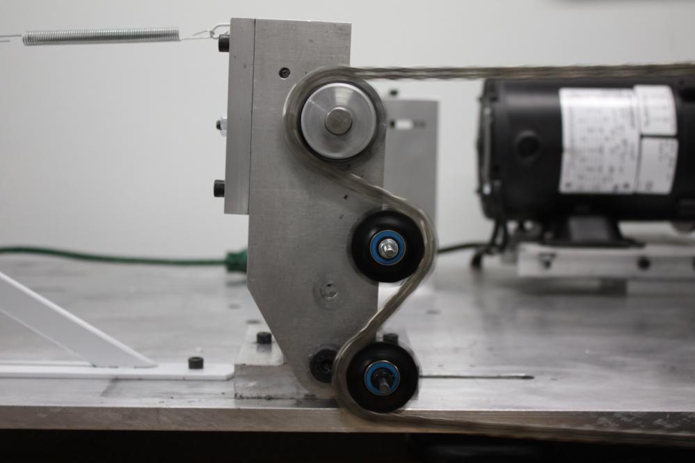
13 - The TACX bearings were broken in for two hours. - When a combination of two different sized pulleys was tested, the smaller of the two pulleys was always placed in the upper position. - The generic pulley wheels were Shimano 105 and Acera wheels. These wheels were chosen due to the ease of machining and low cost (with regard to the test budget). - This test was performed with the pulleys, ring, and cog in a purely coplanar position (no cross chaining). Prior to each combination being tested, the pulleys were aligned to ensure proper coplanar positioning. - For Parts 1 and 2, the constant chain tension of 2.4lbs was chosen based on the average tension applied by a long style cage with an 11T lower pulley. - For Parts 1 and 2, the equipment was set up to allow adjustment of chain span lengths, while maintaining a constant 2.4lbs. I.e., the adjustment of chain span length to accommodate different pulleys size did not affect chain tension. - For Part 3, the top chain span length was fixed (equipment locked), allowing the cage to float and provide the chain tension. However, the top span length was adjusted prior to locking for each of the two cages in order to place each of the two cages in a vertical orientation. - Chain Articulation Angle was used for the X-axis in the line graphs as this is the linear dependent factor of pulley diameter, as opposed to using tooth count for the X-axis. Tooth count does not correspond linearly to the inverse of articulation angle. For example, if an combination was compared to a combination, the total tooth count would be the same and each pulley would be located at the same point along the x-axis of the line graph if plotting teeth count vs. watts. However, this is not accurate. The total articulation angle of the combination is , whereas the total articulation angle of the is Because of this relationship, total articulation angle must be plotted against watts, not tooth count vs. watts. - In addition to increased chain weight and aerodynamic effects, a possible efficiency disadvantage of an oversized pulley system could be friction created by increased lateral moment on the lower pulley created during heavy cross-chaining. This has not been tested, but can be calculated. A simple calculation shows this increased friction would be under 0.01 watts at the maximum cross-chain condition, and decreases to 0.0 watts at a straight-chain-line condition. Worst case scenario calcs: With 2.4lbs at a 10deg angle, this is an approximate lateral load of 0.4 lbs, applied at the edge of the lower pulley. Both small and large pulleys would be subjected to the same lateral loading of 0.4 lbs, however, the moment of the 15T vs 11T is increased by 36%. Knowing the friction of most ceramic pulley bearings is up to 0.05 watts per pulley with 4.4lbs of radial loading, an addition of 0.4 lbs lateral load would most likely increase friction of no more than 0.02 watts. The difference between large and small pulley friction due to the cross-chain lateral load would be 0.02 watts * 36%, or watts. - Crank cadence was 95RPM - A 53T front ring and 12T rear cog was used. - The Tension Test Method was used for measurement. Accuracy of this tester is +/ watts. Additional details can be found at: - Equipment system losses were removed prior to the data presented in this report. - Data was recorded at the end of each chain s 5 minute run with the given pulley combination.
14 SCREEN CAPTURES AND PICTURES OF EACH COMBINATION: 15T-15T Combination. All chains tested in the following order for each combination: Campagnolo, Shimano, SRAM. The peaks represent this order.
15 13T-15T Combination.
16 13T-13T Combination.
17 11T-15T Combination.
18 11T-13T Combination.
19 11T-11T Combination.
20 10T-11T Combination.
21 10T-10T Combination.
22 Dura Ace 13T-13T Combination.
23 RALTech 15T-15T Combination.
24 Berner 13T-15T Combination.
25 CeramicSpeed 11T-11T Combination. Note: the order of the second and third chains, the Shimano and SRAM, were inadvertantly switched for this combination. Does not affect the average.

26 Dura Ace 11T-11T Combination.

27 Berner Cage, Berner 13T-15T Pulleys.
28 DA Cage, DA 11T-11T Pulleys.

29 DA Cage, CeramicSpeed 11T-11T Pulleys.
CHAIN EFFICIENCY TEST, Part 1
 CHAIN EFFICIENCY TEST, Part 1 5 HIGH-END MODELS, FACTORY LUBE SUMMARY OF RESULTS- 5 high-end chains models were tested for efficiency using both the Full Load Test Method (FLT) and Full Tension Test Method
CHAIN EFFICIENCY vs LOAD
 CHAIN EFFICIENCY vs LOAD Goal : To determine 10sp chain efficiency vs load. s: Five models of re-lubed high-end 10sp chains were tested to determine efficiency at various load levels. A single sample of
LESSON Transmission of Power Introduction
 LESSON 3 3.0 Transmission of Power 3.0.1 Introduction Earlier in our previous course units in Agricultural and Biosystems Engineering, we introduced ourselves to the concept of support and process systems
Simple Gears and Transmission
 Simple Gears and Transmission Simple Gears and Transmission page: of 4 How can transmissions be designed so that they provide the force, speed and direction required and how efficient will the design be?
ME3200Practice Questions
 ME3200Practice Questions 5.(15 pts) esign an active low-pass filter with a gain of 5 and a time constant of 50 msec. Use realistic values as were used in lab. 6. (8 pts) A pressure sensor is made by gluing
IMPROVING MOTOR SYSTEM EFFICIENCY WITH HIGH EFFICIENCY BELT DRIVE SYSTEMS
 IMPROVING MOTOR SYSTEM EFFICIENCY WITH HIGH EFFICIENCY BELT DRIVE SYSTEMS Contents Introduction Where to Find Energy Saving Opportunities Power Transmission System Efficiency Enhancing Motor System Performance
Paper Number: DETC
 Proceedings of the th ASME International Power Transmission and Gearing Conference DETC20 August 28-3, 20, Washington, DC, USA Paper Number: DETC20-48494 THE DYNAMIC SIMULATION AND ANALYSIS OF A CYCLOIDAL
Simple Gears and Transmission
 Simple Gears and Transmission Contents How can transmissions be designed so that they provide the force, speed and direction required and how efficient will the design be? Initial Problem Statement 2 Narrative
Team HPV: A Quick Review
 : A Quick Review Prepared By: Tyler Jandreau, Taylor Brown, Jamie Huffman, Joey Stine, Kevin Villa, Matt Strand, Kyle Chapman, Jimmy Woodard, Adam Cooper and is only reproducible with permission of 1 Overall
Monitoring of Shoring Pile Movement using the ShapeAccel Array Field
 2359 Royal Windsor Drive, Unit 25 Mississauga, Ontario L5J 4S9 t: 905-822-0090 f: 905-822-7911 monir.ca Monitoring of Shoring Pile Movement using the ShapeAccel Array Field Abstract: A ShapeAccel Array
KINEMATICS OF MACHINARY UBMC302 QUESTION BANK UNIT-I BASICS OF MECHANISMS PART-A
 KINEMATICS OF MACHINARY UBMC302 QUESTION BANK UNIT-I BASICS OF MECHANISMS PART-A 1. Define the term Kinematic link. 2. Classify kinematic links. 3. What is Mechanism? 4. Define the terms Kinematic pair.
SAE Baja - Drivetrain
 SAE Baja - Drivetrain By Ricardo Inzunza, Brandon Janca, Ryan Worden Team 11A Concept Generation and Selection Document Submitted towards partial fulfillment of the requirements for Mechanical Engineering
Theory of Machines II EngM323 Laboratory User's manual Version I
 Theory of Machines II EngM323 Laboratory User's manual Version I Table of Contents Experiment /Test No.(1)... 2 Experiment /Test No.(2)... 6 Experiment /Test No.(3)... 12 EngM323 Theory of Machines II
Designing a Mechanically Adjustable Speed Drive for AC Motor Applications to Eliminate Vibrations Without Additional Harmonics
 Designing a Mechanically Adjustable Speed Drive for AC Motor Applications to Eliminate Vibrations Without Additional Harmonics Philip Corbin III, Flux Drive Founder/CEO 1. INTRODUCTION: With the advent
Moments. It doesn t fall because of the presence of a counter balance weight on the right-hand side. The boom is therefore balanced.
 Moments The crane in the image below looks unstable, as though it should topple over. There appears to be too much of the boom on the left-hand side of the tower. It doesn t fall because of the presence
Armature Reaction and Saturation Effect
 Exercise 3-1 Armature Reaction and Saturation Effect EXERCISE OBJECTIVE When you have completed this exercise, you will be able to demonstrate some of the effects of armature reaction and saturation in
DEVELOPMENT OF A SUPER COMPACT, HIGH EFFICIENCY, 32-SPEED TRANSMISSION FOR TRACKED VEHICLES
 2016 NDIA GROUND VEHICLE SYSTEMS ENGINEERING AND TECHNOLOGY SYMPOSIUM POWER & MOBILITY (P&M) TECHNICAL SESSION AUGUST 2-4, 2016 - NOVI, MICHIGAN DEVELOPMENT OF A SUPER COMPACT, HIGH EFFICIENCY, 32-SPEED
Chapter 7: DC Motors and Transmissions. 7.1: Basic Definitions and Concepts
 Chapter 7: DC Motors and Transmissions Electric motors are one of the most common types of actuators found in robotics. Using them effectively will allow your robot to take action based on the direction
The Mechanics of Tractor Implement Performance
 The Mechanics of Tractor Implement Performance Theory and Worked Examples R.H. Macmillan CHAPTER 2 TRACTOR MECHANICS Printed from: http://www.eprints.unimelb.edu.au CONTENTS 2.1 INTRODUCTION 2.1 2.2 IDEAL
Cooling Enhancement of Electric Motors
 Cooling Enhancement of Electric Motors Authors : Yasser G. Dessouky* and Barry W. Williams** Dept. of Computing & Electrical Engineering Heriot-Watt University Riccarton, Edinburgh EH14 4AS, U.K. Fax :
TRANSLATION (OR LINEAR)
") 5) Load Bearing Mechanisms Load bearing mechanisms are the structural backbone of any linear / rotary motion system, and are a critical consideration. This section will introduce most of the more common
5) Load Bearing Mechanisms Load bearing mechanisms are the structural backbone of any linear / rotary motion system, and are a critical consideration. This section will introduce most of the more common
Grade 8 Science. Unit 4: Systems in Action
 Grade 8 Science Unit 4: Systems in Action Machines That Turn Last class we looked at the idea of a boat winch, a wheel and axle used to get a boat out of the water, onto a trailer. You rotate the handle
CHAPTER 6 GEARS CHAPTER LEARNING OBJECTIVES
 CHAPTER 6 GEARS CHAPTER LEARNING OBJECTIVES Upon completion of this chapter, you should be able to do the following: Compare the types of gears and their advantages. Did you ever take a clock apart to
Table 1. Sample Identification and Comparison Connectors Used in Experiments Sample Conductor Size
 Background Information and Purpose Underground cable electrical collection systems have become common in renewable generation system applications (wind farms and solar farms). However, the nature of these
Department of Mechanical Engineering University of Engineering & Technology Lahore(KSK Campus).
.") Department of Mechanical Engineering University of Engineering & Technology Lahore(KSK Campus). LAB DATA Lab Incharge: Engr. Muhammad Amjad Lab Assistant: Abbas Ali Lay-Out of Mechanics of Machines Lab
Department of Mechanical Engineering University of Engineering & Technology Lahore(KSK Campus). LAB DATA Lab Incharge: Engr. Muhammad Amjad Lab Assistant: Abbas Ali Lay-Out of Mechanics of Machines Lab
University of TN Chattanooga Physics 1040L 8/28/2012
 PHYSICS 1040L LAB 5: MAGNETIC FIELD Objectives: 1. Determine the relationship between magnetic field and the current in a solenoid. 2. Determine the relationship between magnetic field and the number of
Riverhawk Company 215 Clinton Road New Hartford NY (315) Free-Flex Flexural Pivot Engineering Data
 Free-Flex Flexural Pivot Engineering Data") Riverhawk Company 215 Clinton Road New Hartford NY (315)768-4937 Free-Flex Flexural Pivot Engineering Data PREFACE Patented Flexural Pivot A unique bearing concept for applications with limited angular
Riverhawk Company 215 Clinton Road New Hartford NY (315)768-4937 Free-Flex Flexural Pivot Engineering Data PREFACE Patented Flexural Pivot A unique bearing concept for applications with limited angular
Self-Adjust Clutch Installation Guide
 Self-Adjust Clutch Installation Guide 0 STOP! READ CAREFULLY BEFORE INSTALLING CLUTCH This clutch must be installed by a qualified installer. Improper installation or failure to replace or resurface the
Introducing Galil's New H-Bot Firmware
 March-16 Introducing Galil's New H-Bot Firmware There are many applications that require movement in planar space, or movement along two perpendicular axes. This two dimensional system can be fitted with
The Magnetic Field. Magnetic fields generated by current-carrying wires
 OBJECTIVES The Magnetic Field Use a Magnetic Field Sensor to measure the field of a long current carrying wire and at the center of a coil. Determine the relationship between magnetic field and the number
A Practical Guide to Free Energy Devices
 A Practical Guide to Free Energy Devices Part PatD20: Last updated: 26th September 2006 Author: Patrick J. Kelly This patent covers a device which is claimed to have a greater output power than the input
Gear Ratios and Speed Background Material
 VEX Robotics Lab 3 How Do Gear Ratios Affect and Torque? Introduction In this investigation, students will learn the relationships between gear ratio, axle speed, and torque. Students will use the Vex
Smart Automated Vent Register Using an SMA Spring Actuated Rotary Ratchet
 Smart Automated Vent Register Using an SMA Spring Actuated Rotary Ratchet Mary Molepske, Victor Braciszewski, James Butler, Gregory Caputo, Fan-Ning Cheng, WonHee Kim, Jonathan Luntz, Diann Brei ABSTRACT
DESIGN AND SELECTION OF BEARINGS AND HOUSINGS USED IN MATERIAL HANDLING APPLICATIONS
 DESIGN AND SELECTION OF BEARINGS AND HOUSINGS USED IN MATERIAL HANDLING APPLICATIONS SPHERICAL ROLLER BEARINGS M. STEWART-LORD MANAGER - APPLICATION ENGINEERING SKF SOUTH AFRICA (PTY) LTD (SA) Spherical
RNRG WHITE PAPER Early Detection of High Speed Bearing Failures
 BACKGROUND RNRG worked with a large wind turbine owner in North America to demonstrate that the TurbinePhD condition monitoring system can detect faults early and reduce maintenance costs. An evaluation
Original. M. Pang-Ngam 1, N. Soponpongpipat 1. Keywords: Optimum pipe diameter, Total cost, Engineering economic
 Original On the Optimum Pipe Diameter of Water Pumping System by Using Engineering Economic Approach in Case of Being the Installer for Consuming Water M. Pang-Ngam 1, N. Soponpongpipat 1 Abstract The
Design & Development of Regenerative Braking System at Rear Axle
 International Journal of Advanced Mechanical Engineering. ISSN 2250-3234 Volume 8, Number 2 (2018), pp. 165-172 Research India Publications http://www.ripublication.com Design & Development of Regenerative
Electric Motors and Drives
 EML 2322L MAE Design and Manufacturing Laboratory Electric Motors and Drives To calculate the peak power and torque produced by an electric motor, you will need to know the following: Motor supply voltage:
CHAPTER 1 MECHANICAL ARRANGEMENT
 CHAPTER 1 CHAPTER 1 MECHANICAL ARRANGEMENT CONTENTS PAGE Basic Principals 02 The Crankshaft 06 Piston Attachment 08 Major Assemblies 10 Valve Gear 12 Cam Drive 18 Mechanical Arrangement - Basic Principals
ME scope Application Note 25 Choosing Response DOFs for a Modal Test
 ME scope Application Note 25 Choosing Response DOFs for a Modal Test The steps in this Application Note can be duplicated using any ME'scope Package that includes the VES-3600 Advanced Signal Processing
Lower-Loss Technology
 Lower-Loss Technology FOR A STEPPING MOTOR Yasuo Sato (From the Fall 28 Technical Conference of the SMMA. Reprinted with permission of the Small Motor & Motion Association.) Management Summary The demand
Exercise 2-1. The Separately-Excited DC Motor N S EXERCISE OBJECTIVE DISCUSSION OUTLINE DISCUSSION. Simplified equivalent circuit of a dc motor
 Exercise 2-1 The Separately-Excited DC Motor EXERCISE OBJECTIVE When you have completed this exercise, you will be able to demonstrate the main operating characteristics of a separately-excited dc motor
Step Motor Lower-Loss Technology An Update
 Step Motor Lower-Loss Technology An Update Yatsuo Sato, Oriental Motor Management Summary The demand for stepping motors with high efficiency and low losses has been increasing right along with the existing
Application Information
 Moog Components Group manufactures a comprehensive line of brush-type and brushless motors, as well as brushless controllers. The purpose of this document is to provide a guide for the selection and application
Chapter 4. Vehicle Testing
 Chapter 4 Vehicle Testing The purpose of this chapter is to describe the field testing of the controllable dampers on a Volvo VN heavy truck. The first part of this chapter describes the test vehicle used
Product Range Modules ROSTA Tensioner Devices
 Product Range Modules ROSTA Page 17 14 Tensioning Technology Chain Tensioning Roller chains are power transmission components with positive transmission which, by virtue of their design are subject, depending
ANTI-BACKLASH GEAR TRAIN INVESTIGATION. Zengxin Gao, Jani Tähtinen
 Zengxin Gao, Jani Tähtinen Wärtsilä Finland Oy Järvikatu 2-4, P.O. Box 244 FI-65101 Vaasa zengxin.gao@wartsila.com jani.tahtinen@wartsila.com 1 INTRODUCTION This paper is a continuation of study on Wärtsilä
The Magnetic Field in a Slinky
 The Magnetic Field in a Slinky A solenoid is made by taking a tube and wrapping it with many turns of wire. A metal Slinky is the same shape and will serve as our solenoid. When a current passes through
Introduction: Supplied to 360 Test Labs... Battery packs as follows:
 2007 Introduction: 360 Test Labs has been retained to measure the lifetime of four different types of battery packs when connected to a typical LCD Point-Of-Purchase display (e.g., 5.5 with cycling LED
Orientalmotor. Development of K II Series Hypoid Geared Motor
 Development of K II Series Hypoid Geared Motor The motor industry was looking for a geared motor that would downsize, reduce loss and provide high torque. This led our company to develop the K II series,
Anti-Cog Technology. Introduction
 Anti-Cog Technology Introduction Ironcore linear motors have traditionally suffered from a phenomenon known as cogging. This is seen as a periodically varying resistive force when the motor is pushed by
An Experimental Study on the Efficiency of Bicycle Transmissions
 An Experimental Study on the Efficiency of Bicycle Transmissions R. Bolen and C. M. Archibald Grove City College, Grove City, PA Abstract: The objective of this project is to measure the efficiencies of
Designing Drive Systems for Low Web Speeds
 Designing Drive Systems for Low Web Speeds Web Tension Control at Low Speeds Very low web speeds can provide challenges to implementing drive systems with accurate tension control. UNWIND LOAD CELL COOLING
Is Low Friction Efficient?
 Is Low Friction Efficient? Assessment of Bearing Concepts During the Design Phase Dipl.-Wirtsch.-Ing. Mark Dudziak; Schaeffler Trading (Shanghai) Co. Ltd., Shanghai, China Dipl.-Ing. (TH) Andreas Krome,
Executive Summary: Design of a Small Scale Wind Turbine to Improve Drinking Water in Garacad, Somalia
 Executive Summary: Design of a Small Scale Wind Turbine to Improve Drinking Water in Garacad, Somalia Khalifa Alsuwaidi, Austin Kiker, and Robert Napoli Team 6.4, ME 340, Mechanical Engineering Department,
FEASIBILITY STYDY OF CHAIN DRIVE IN WATER HYDRAULIC ROTARY JOINT
 FEASIBILITY STYDY OF CHAIN DRIVE IN WATER HYDRAULIC ROTARY JOINT Antti MAKELA, Jouni MATTILA, Mikko SIUKO, Matti VILENIUS Institute of Hydraulics and Automation, Tampere University of Technology P.O.Box
Driver Driven. InputSpeed. Gears
 Gears Gears are toothed wheels designed to transmit rotary motion and power from one part of a mechanism to another. They are fitted to shafts with special devices called keys (or splines) that ensure
Development of Super-low Friction Torque Technology for Tapered Roller Bearing
 TECHNICAL PAPER Development of Super-low Friction Torque Technology for Tapered Roller Bearing H. MATSUYAMA H. DODORO K. OGINO H. OHSHIMA H. CHIBA K. TODA To achieve high efficiency in rear axle differentials,
The development of a differential for the improvement of traction control
 The development of a differential for the improvement of traction control S E CHOCHOLEK, BSME Gleason Corporation, Rochester, New York, United States of America SYNOPSIS: An introduction to the function
Ball. Ball cage. Fig.1 Structure of Caged Ball LM Guide Actuator Model SKR
 Caged all LM Guide Actuator Model Inner block all screw shaft Grease nipple Outer rail all cage all Structure and Features Fig.1 Structure of Caged all LM Guide Actuator Model Caged all LM Guide Actuator
Stopping Accuracy of Brushless
 Stopping Accuracy of Brushless Features of the High Rigidity Type DGII Series Hollow Rotary Actuator The DGII Series hollow rotary actuator was developed for positioning applications such as rotating a
Reduction of Self Induced Vibration in Rotary Stirling Cycle Coolers
 Reduction of Self Induced Vibration in Rotary Stirling Cycle Coolers U. Bin-Nun FLIR Systems Inc. Boston, MA 01862 ABSTRACT Cryocooler self induced vibration is a major consideration in the design of IR
EEL Project Design Report: Automated Rev Matcher. January 28 th, 2008
 Brad Atherton, masscles@ufl.edu, 352.262.7006 Monique Mennis, moniki@ufl.edu, 305.215.2330 EEL 4914 Project Design Report: Automated Rev Matcher January 28 th, 2008 Project Abstract Our device will minimize
The sphere roller Less is more!
 The sphere roller Less is more! Heinrich Hofmann Rainer Eidloth Dr. Robert Plank Gottfried Ruoff 109 8 The sphere roller Introduction Wheel supported by balls It started with the point, then along came
The Mechanical Equivalent of Heat
 The Mechanical Equivalent of Heat INTRODUCTION One of the most famous experiments of the 19 th century was Joule s experiment showing that mechanical energy can be converted to heat. This showed that heat
Turbo boost. ACTUS is ABB s new simulation software for large turbocharged combustion engines
 Turbo boost ACTUS is ABB s new simulation software for large turbocharged combustion engines THOMAS BÖHME, ROMAN MÖLLER, HERVÉ MARTIN The performance of turbocharged combustion engines depends heavily
Special edition paper
 Countermeasures of Noise Reduction for Shinkansen Electric-Current Collecting System and Lower Parts of Cars Kaoru Murata*, Toshikazu Sato* and Koichi Sasaki* Shinkansen noise can be broadly classified
Richard Hull s Mysterious Motor
 Update June 2009: The following is some updated information regarding http://www.mtaonline.net/~hheffner/hullmotor.pdf fig. 3 provided below is an improved version of Fig. 3 in the above original work.
INFLUENCE OF CROSS FORCES AND BENDING MOMENTS ON REFERENCE TORQUE SENSORS FOR TORQUE WRENCH CALIBRATION
 XIX IMEKO World Congress Fundamental and Applied Metrology September 6 11, 2009, Lisbon, Portugal INFLUENCE OF CROSS FORCES AND BENDING MOMENTS ON REFERENCE TORQUE SENSORS FOR TORQUE WRENCH CALIBRATION
Driven Damped Harmonic Oscillations
 Driven Damped Harmonic Oscillations Page 1 of 8 EQUIPMENT Driven Damped Harmonic Oscillations 2 Rotary Motion Sensors CI-6538 1 Mechanical Oscillator/Driver ME-8750 1 Chaos Accessory CI-6689A 1 Large Rod
ROSTA Tensioner Devices
 33 Tensioning Technology Chain Tensioning Roller chains are power transmission components with positive transmission which, by virtue of their design are subject, depending on quality, to elongation as
Lab 2 Electrical Measurements and Ohm s Law
 Lab 2 Electrical Measurements and Ohm s Law Safety and Equipment No special safety precautions are necessary for this lab. Computer with PASCO Capstone, PASCO 850 Universal Interface Double banana/alligator
Coriolis Density Error Compensating for Ambient Temperature Effects
 Coriolis Density Error Compensating for Ambient Temperature Effects Presented by Gordon Lindsay Oil & Gas Focus Group December 2018 Contents Project aims and objectives Experiment Setup Phase 1 Exploratory
Clutch Installation Guide
 Clutch Installation Guide 0 STOP! READ CAREFULLY BEFORE INSTALLING CLUTCH This clutch must be installed by a qualified installer. Improper installation or failure to replace or resurface the flywheel,
STICTION/FRICTION IV STICTION/FRICTION TEST 1.1 SCOPE
 Page 1 of 6 STICTION/FRICTION TEST 1.0 STICTION/FRICTION TEST 1.1 SCOPE Static friction (stiction) and dynamic (running) friction between the air bearing surface of sliders in a drive and the corresponding
PHYS 2212L - Principles of Physics Laboratory II
 PHYS 2212L - Principles of Physics Laboratory II Laboratory Advanced Sheet Faraday's Law 1. Objectives. The objectives of this laboratory are a. to verify the dependence of the induced emf in a coil on
Manipulators. Example 1: The Claw
 Manipulators With these examples we will demonstrate some basic designs to accomplish each of the game piece challenges involved in the 2018 FIRST Global game Energy Impact to: 1. Collect fuel cubes and
NORTHERN ILLINOIS UNIVERSITY PHYSICS DEPARTMENT. Physics 211 E&M and Quantum Physics Spring Lab #6: Magnetic Fields
 NORTHERN ILLINOIS UNIVERSITY PHYSICS DEPARTMENT Physics 211 E&M and Quantum Physics Spring 2018 Lab #6: Magnetic Fields Lab Writeup Due: Mon/Wed/Thu/Fri, March 5/7/8/9, 2018 Background Magnetic fields
TYPICAL EXPERIMENTS Centers of gravity. Force triangle. Force polygon and Bow s Notation. Non- concurrent forces.
 MM 500-001 BASIC PANEL The panel is made from a perforated stainless steel sheet mounted on two supports with adjustable footings. The panel can be tilted, put in portrait or landscape position. Accessories
Singh Groove Concept Combustion Analysis using Ionization Current By: Garrett R. Herning AutoTronixs, LLC. October 2007
 Singh Groove Concept Combustion Analysis using Ionization Current By: Garrett R. Herning AutoTronixs, LLC. October 2007 Ionization Current: Ionization current is a method devised of using the spark plug
Lab #3 - Slider-Crank Lab
 Lab #3 - Slider-Crank Lab Revised March 19, 2012 INTRODUCTION In this lab we look at the kinematics of some mechanisms which convert rotary motion into oscillating linear motion and vice-versa. In kinematics
Evaluation copy. The Magnetic Field in a Slinky. computer OBJECTIVES MATERIALS INITIAL SETUP
 The Magnetic Field in a Slinky Computer 26 A solenoid is made by taking a tube and wrapping it with many turns of wire. A metal Slinky is the same shape and will serve as our solenoid. When a current passes
AS Series. RK Series. UMK Series ASX Series 0.36 /0.72. CRK Series. CMK Series 1.8. RBK Series. PK Series 1.
 A Stepping Motors Stepping Motors Introduction A-2 Introduction AC Input Stepping Motor and Driver Packages DC Input Stepping Motor and Driver Packages Stepping Motors (Motor Only) A-269 A-24 High Efficiency
} Rev.1/Add.12/Rev.6/Amend.4
 30 December 2009 AGREEMENT CONCERNING THE ADOPTION OF UNIFORM TECHNICAL PRESCRIPTIONSFOR WHEELED VEHICLES, EQUIPMENT AND PARTS WHICH CAN BE FITTEDAND/OR BE USED ON WHEELED VEHICLES AND THE CONDITIONS FOR
Exploring Electric Vehicle Battery Charging Efficiency
 September 2018 Exploring Electric Vehicle Battery Charging Efficiency The National Center for Sustainable Transportation Undergraduate Fellowship Report Nathaniel Kong, Plug-in Hybrid & Electric Vehicle
R310EN 2211 ( ) The Drive & Control Company
 The Drive & Control Company") eline Ball Rail Systems R310EN 2211 (2006.04) The Drive & Control Company Bosch Rexroth AG Linear Motion and Assembly Technologies Ball Rail Systems Roller Rail Systems Linear Bushings and Shafts Ball
eline Ball Rail Systems R310EN 2211 (2006.04) The Drive & Control Company Bosch Rexroth AG Linear Motion and Assembly Technologies Ball Rail Systems Roller Rail Systems Linear Bushings and Shafts Ball
Transmission Error in Screw Compressor Rotors
 Purdue University Purdue e-pubs International Compressor Engineering Conference School of Mechanical Engineering 2008 Transmission Error in Screw Compressor Rotors Jack Sauls Trane Follow this and additional
Mechanical Motion. Control Components. and Subsystems. Understanding How Components Effect System Performance
 Mechanical Motion Control Components and Subsystems Understanding How Components Effect System Performance Mechanical Motion Control Components and Subsystems Overview: Bearings Linear Bearing Technologies
Self-Adjusting Clutch (SAC) Technology Special tools / User instructions
 Technology Special tools / User instructions") Self-Adjusting Clutch (SAC) Technology Special tools / User instructions The content of this brochure shall not be legally binding and is for information purposes only. To the extent legally permissible,
Self-Adjusting Clutch (SAC) Technology Special tools / User instructions The content of this brochure shall not be legally binding and is for information purposes only. To the extent legally permissible,
High Load Capacity Cylindrical Roller Bearings
 NTN TECHNICAL REVIEW No.7426 New Product High Load Capacity Cylindrical Roller Bearings Takuya OZU NTN has developed high load capacity cylindrical roller bearings appropriate for gearbox of wind turbines
NEXEN WHITEPAPER. Nexen Group, Inc. 560 Oak Grove Parkway / Vadnais Heights, MN /
 NEXEN WHITEPAPER Roller Versatility, Pinion Precision Systemand Short Lead Times: The CRD MR Rotary Indexer Nexen s new indexer is a cost-effective solution for automating a wide variety of tasks. Whether
Determination and improvement of bevel gear efficiency by means of loaded TCA
 Determination and improvement of bevel gear efficiency by means of loaded TCA Dr. J. Thomas, Dr. C. Wirth, ZG GmbH, Germany Abstract Bevel and hypoid gears are widely used in automotive and industrial
Ch# 11. Rolling Contact Bearings 28/06/1438. Rolling Contact Bearings. Bearing specialist consider matters such as
 Ch# 11 Rolling Contact Bearings The terms rolling-contact bearings, antifriction bearings, and rolling bearings are all used to describe the class of bearing in which the main load is transferred through
Application Notes. Calculating Mechanical Power Requirements. P rot = T x W
 Application Notes Motor Calculations Calculating Mechanical Power Requirements Torque - Speed Curves Numerical Calculation Sample Calculation Thermal Calculations Motor Data Sheet Analysis Search Site
Operability and Performance Analysis of Various Control Valves
 Murdoch University Operability and Performance Analysis of Various Control Valves Final Report Jasmine Herbert 15 Abstract In 15 an assortment of control valves were implemented in the Murdoch University
APPLICATION NOTE Calculating temperature rise when mounting remote access units into Oberon s Model 1074 Ceiling Zone enclosures
 APPLICATION NOTE Calculating temperature rise when mounting remote access units into Oberon s Model 1074 Ceiling Zone enclosures Introduction to Thermal Considerations When mounting active (powered) equipment
R310EN 2302 ( ) The Drive & Control Company
 The Drive & Control Company") R31EN 232 (26.4) The Drive & Control Company Bosch Rexroth AG Linear Motion and Assembly Technologies Ball Rail Systems Linear Bushings and Shafts Ball Screw Drives Linear Motion Systems Basic Mechanical
R31EN 232 (26.4) The Drive & Control Company Bosch Rexroth AG Linear Motion and Assembly Technologies Ball Rail Systems Linear Bushings and Shafts Ball Screw Drives Linear Motion Systems Basic Mechanical
A New Device to Measure Instantaneous Swept Volume of Reciprocating Machines/Compressors
 Purdue University Purdue e-pubs International Compressor Engineering Conference School of Mechanical Engineering 2004 A New Device to Measure Instantaneous Swept Volume of Reciprocating Machines/Compressors
Servo Creel Development
 Servo Creel Development Owen Lu Electroimpact Inc. owenl@electroimpact.com Abstract This document summarizes the overall process of developing the servo tension control system (STCS) on the new generation
Verifying the accuracy of involute gear measuring machines R.C. Frazer and J. Hu Design Unit, Stephenson Building, University ofnewcastle upon Tyne,
 Verifying the accuracy of involute gear measuring machines R.C. Frazer and J. Hu Design Unit, Stephenson Building, University ofnewcastle upon Tyne, Abstract This paper describes the most common methods