High-Performance Universal Joint Shafts. Products Engineering Service
|
|
|
- Ernest Franklin
- 6 years ago
- Views:
Transcription

1 High-Performance Universal Joint Shafts. Products Engineering Service

2 Universal Joint Shafts and Hirth Couplings At Voith, we are the experts when it comes to Cardan drive elements and radial tooth couplings. Voith sets standards in the energy, oil & gas, paper, raw materials and transportation & automotive markets. Founded in 1867, Voith employs more than people, generates Euro 5.7 billion in sales, operates in about 50 countries around the world and is today one of the largest family-owned companies in Europe. 2
3 Contents 1 Voith high-performance universal joint shafts What makes them unique? 2 Range 6 3 Designs Center sections Flanges Type designations 9 4 Applications 10 5 Definitions and abbreviations Lengths Torques 15 6 Technical data S Series R Series CH Series E Series 29 7 Engineering basics Major components of a Voith universal joint shaft Length compensation with spline shaft profile Length compensation with roller bearing tripod universal joint shafts 7.4 Universal joint kinematics Double universal joint Bearing forces on input and output shafts Balancing of universal joint shafts Choosing a solution Definitions of operating variables Size selection Operating speeds Masses Connection flanges and bolted connections 60 9 Service Installation and commissioning Training Voith original spare parts Overhaul and maintenance Repairs and reconditioning Modernizations and retrofits Services and accessories Engineering Connection components for universal joint shafts Quick release coupling GT Voith Hirth coupling Universal joint shaft support systems Universal joint shafts with carbon fiber-reinforced polymer (CFRP) 10.7 High-performance lubricant for universal joint shafts SafeSet torque limiting safety couplings ACIDA torque monitoring systems Integrated management system Quality Environment Occupational health and safety 85 3


4 1 2 1 Voith High-Performance Universal Joint Shafts What makes them unique? Features Closed bearing eye Drop-forged journal crosses FEM-optimized geometry High-strength tempered and case-hardened steels Load-optimized welded joints Length compensation with SAE profile (straight flank profile) for larger series Patented balancing procedure Engineering and product from a single source Advantages Heavy-duty cross-sections without joints or bolts Minimal notch stresses Enclosed seal surfaces Best possible torque capacity Optimal design for force flow Minimal notch stresses Capability to withstand high static and dynamic loads Optimal design for force flow Lower normal forces and thus lower displacement forces Low surface pressure High wear resistance Dynamic balancing in two planes Balancing mass where unbalanced forces act One contact person when designing the driveline Certification and classification for rail vehicles, ships, boats and for potentially explosive atmospheres (ATEX, etc.) Made in Germany Voith Engineered Reliability Officially approved product Seal of approval for quality, efficiency and precision Competent and trustworthy partner 4


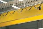
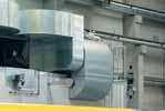
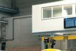
5 3 4 1 Assembly hall for Voith universal joint shafts 2 Welding robot 3 Balancing machine 4 Shipping Benefits + Increased productivity + Long service life + Ease of movement + Long service life + Extremely smooth operation + Time and cost savings + Single-source responsibility + Time and cost savings + Reliability + Innovative product and system solutions 5
6 2 Range Voith high-performance universal joint shafts offer the ideal combination of torque capacity, torsion and bending rigidity. We supply everything from standard universal joint shafts to customer-specific adaptations and custom designs. And our wide range of services includes technical consultation, simulation of torsional vibrations and measurement of operating parameters. Series Torque range M Z [knm] Flange diameter a [mm] S 0.25 to to 225 R 32 to to 550 CH 260 to to E to to
7 Features Basic version of Voith universal joint shafts Non-split bearing eyes thanks to single-piece forged flange yoke Length compensation with involute profile Applications Paper machinery Pumps General mechanical engineering Ships and boats Rail vehicles Test rigs Construction machinery and cranes High torque capacity Optimized bearing life Flange in friction and positive locking design (see page 9) Length compensation with involute profile up to size 315; SAE profile starting from size 350 (straight flank profile, see page 34); optional tripod (see page 36) Optimized torsional rigidity and deflection resistance in a low-weight design Particularly well-suited for use with high-speed drives Optional: Low-maintenance length compensation using plastic-coated (Rilsan ) involute profile Rolling mill drives Drives in general mechanical engineering tasks Paper machinery Pumps Ships and boats Rail vehicles Very high torque capacity Optimized bearing life One-piece flange yokes (integrated) Flange yokes (neck / neckless) Flange with Hirth coupling to transmit maximum torque Length compensation with SAE profile (straight flank profile, see page 34) Rolling mill drives Construction of heavy machinery Paper machinery Maximum torque capacity Optimized bearings for exceptionally demanding requirements Patented 2-piece flange yoke (semi-integrated) Flange yokes (neckless) Flange with Hirth coupling to transmit maximum torque Length compensation with SAE profile (straight flank profile, see page 34) Heavy-duty rolling mill drives 7
8 3 Designs 3.1 Center sections Type Description T Universal joint shaft with standard length compensation TL Universal joint shaft with extended length compensation TK Universal joint shaft with short length compensation TR Universal joint shaft with tripod length compensation F Universal joint shaft without length compensation (fixed-length shaft) GK Joint coupling: short, separable universal joint shaft without length compensation FZ Intermediate shaft with a single joint and bearing Z Intermediate shaft with double bearing 8
9 3.2 Flanges Type Description Type Description S Friction flange, torque transmission by a friction locking connection K Flange with split sleeves for torque transmission (DIN 15451) Q Flange with face key for torque transmission H Flange with Hirth coupling for torque transmission 3.3 Type designations Example R T S 285 / Q 250 R Series S, R, CH, E Center-section design T, TL, TK1, TK2, TK3, TK4, TR, F, GK, FZ, Z Size Flange design and size input side / output side (see Section 7.1, page 32) S, K, Q, H Profile design S : Steel on steel (standard) R : Rilsan coating on steel P : PTFE coating on steel : for types TR, F, GK, FZ, Z Length l, l z or l fix in mm 9
10 1 10


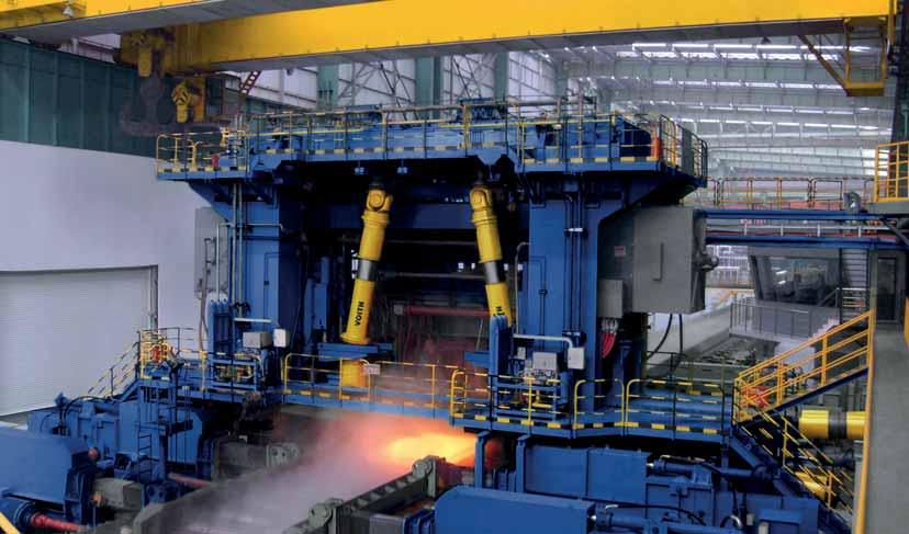
11 2 3 4 Rolling mills 1 Edging mill stand 2 Edging mill stand 3 Horizontal rolling stand 4 Straightening machine 4 Applications 11
12 1 2 12


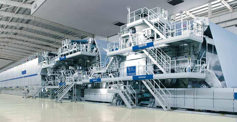
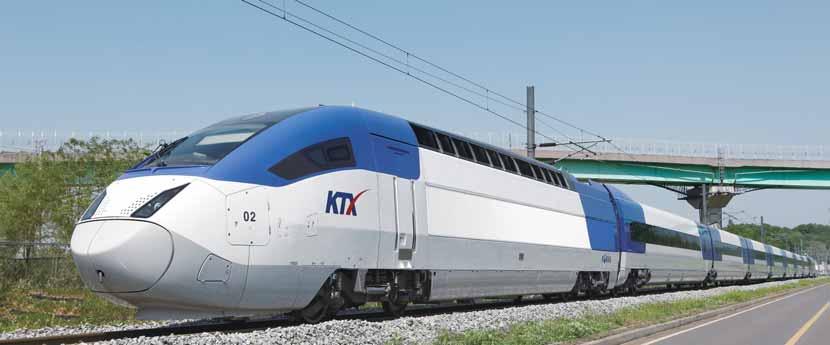
13 Rail vehicle drives 2 Paper machines 3 Ship propulsion systems 4 Test rigs 5 Pumps 6 Special drives (mine hoist) 13
14 5 Defi nitions and Abbreviations 5.1 Lengths Universal joint shaft with length compensation Universal joint shaft without length compensation l B, max l z l v l B ( = l ) l B : Operating length (Please indicate with order.) l z : Shortest length of the universal joint shaft (fully collapsed) l B : Operating length, corresponds to the universal joint shaft length l (Please indicate with order.) l v : Available length compensation The distance between the driving and the driven machines, together with any length changes during operation, determines the operating length: Optimal operating length: l B,opt l z + l v 3 Maximum permissible operating length: l B,max = l z + l v 14
15 5.2 Torques Components Designation Explanation Components M DW Reversing fatigue torque rating. The shaft will have an infinite fatigue life up to this torque level. M DS M K Pulsating one-way fatigue torque rating. The shaft will have an infinite fatigue life up to this torque level. Where: M DS 1.5 M DW Maximum permissible torque. If this level is exceeded, plastic deformation may occur. Values available on request. Bearing M Z Permissible torque for rarely occurring peak loads. Bearing races may suffer plastic deformation at torque levels in excess of M Z. This can lead to a reduced bearing life. CR Load rating for bearings - when used with operating values, enables calculation of theoretical bearing life L h (see Section 8.2.1, page 52). Flange connections Custom designed. Torque definitions Note M (t) M Z M DS M DW, M DS and M Z are load limits for the universal joint shaft. For torque values close to the load limit, the transmission capacity of the flange connection must be checked, especially in cases where friction lock is employed. M DW 0 t Pulsating load Alternating load 15
16 6 Technical Data 6.1 S Series The S Series is the basic version of universal joint shaft and is designed for mid-range drives. The connection flanges are designed as friction flanges. SF SGK l l fix General specifications ST 1 Size M z M DW CR β max a k b ±0.1 c H7 h B12 l m r t z g LA l v [knm] [knm] [knm] [ ] x A, B x A, B x A, B x A, B, C x A, B, C x A, B, C x A, B, C x C x C x C x C x C 140 Dimensions in mm. 1 Longer l v available on request. 16
17 ST / STK l z l m øb øb øb t g SFZ SZ l l l d l d ød ød øc øa øb øk ør l v z = 4 øh øh øh z = 6 z = 8 t a g a t a g a LA: Length compensation A: Steel on steel, no profile protection B: Steel on steel, with profile protection C: Rilsan coating on steel with profile protection D: PTFE coating on steel, with profile protection STK 1 STK 2 STK 3 STK 4 2 SF SGK SFZ SZ SFZ, SZ I z min LA l v I z fix LA l v I z fix LA l v I z fix LA l v I z fix I min I fix I min I min I d d g a t a 240 B B B B B B B B B B B B B, C B, C B, C B, C B, C B, C B, C B, C B, C B, C B, C B, C B, C B, C B, C B, C C C C C C C C C C C C D C C C C C C C D Shorter l Z available on request. 17
18 6.2 R Series R Series universal joint shafts are the best solution for medium-sized torques and especially for high-speed drives. These universal joint shafts are of modular design and can be integrated into your drives with a great deal of flexibility. Flange connections are available in friction and positive locking designs. RF RGK l l fix General specifications RT RTL 1 Size M z M DW CR β max k l m r LA l v I z min LA l v I z min [knm] [knm] [knm] [ ] x 10 C x 12.5 B, C B, C x 12.5 B, C B, C x 12.5 B, C B, C x 16 B, C B, C x 22.2 B B x 25 B B x 28 B B x 32 B B x 32 B B Dimensions in mm. 1 Longer l v available on request. 18
19 RT / RTL / RTK l z l m øk ør l v RFZ RZ l l l d l d ød ød t a g a t a g a LA: Length compensation B: Steel on steel, with profile protection C: Rilsan coating on steel with profile protection RTK 1 RTK 2 2 RF RGK RFZ RZ RFZ, RZ LA l v I z fix LA l v I z fix I min I fix I min I min l d d g a t a B, C B, C B, C B, C B, C B, C B, C B, C B B B B B B B B B B Shorter l Z available on request. Flange dimensions: Pages 20 to
20 S flange: friction flange øb øb øa øb øc øk t g øh z = 8 z = 10 øh k a b ±0.2 c H7 g h C12 t z Note Standard Torque M DW = 18 knm Standard Torque M DW = 25 knm Standard Torque M DW = 36 knm Standard Torque M DW = 52 knm Standard Torque M DW = 75 knm Standard Torque M DW = 100 knm Standard Dimensions in mm. Additional fl anges available on request. 20
21 Q flange: flange with face key y øb øb øb øa øb øc x øk t g øh øh øh z = 8 z = 10 z = 16 k a b ±0.2 c H7 g h t x h9 y z Note Standard Standard Standard Standard Standard Standard Standard Standard Standard Dimensions in mm. Additional fl anges available on request. 21
22 45 K flange: flange with split sleeves øa øb øc øk øb øb ød ød øe øe t g øh z = z = øh k a b ±0.2 c H7 g h C12 t z d e H12 Note Standard Standard Standard Standard Standard Standard Standard Dimensions in mm. Additional fl anges available on request. 22
23 H flange: flange with Hirth coupling øb øb øb øa øb øc øk g øh øh øh z = 4 z = 6 z = 8 k a b ±0.2 c g h u 1 z Note Standard Standard Standard Standard Standard Standard Standard Standard Standard Dimensions in mm. Bore positioned on tooth gap. 1 Number of teeth on Hirth coupling. Additional fl anges available on request. 23


24 6.3 CH Series The CH Series is the standard for high and maximum torque applications. CH universal joint shafts are individually designed, that is, they are built to customer specifications. They precisely match the requirements of the drive. Flanges and flange yokes are available in a wide variety of designs and materials Flange yokes We use our wide variety of one-piece flange yoke (integrated) designs to adapt the universal joint shaft to your drive. Your universal joint shaft is optimally dimensioned to achieve the best possible balance between performance, reliability, and cost. Designs Design models Neckless Standard With neck With oversize flange M DW approx. 5 % less than with standard design M DW same as for standard design Materials Forged steel Standard Cast steel M DW approx. 20 % less than with standard design Neckless With neck With oversize flange (neckless) Flange yoke 24
25 6.3.2 Joint and bearing concept The concept underlying the CH Series bearings is based on decades of experience in designing high-performance universal joint shafts. During its development, engineers focused on low life cycle costs and a high level of operational reliability. How we build it Radial and axial bearings are combined to a single unit (cassette bearings). The radial and axial bearings are low-friction roller bearings. Inner and outer rings are produced from special bearing steel. The geometry of the flange yokes has been optimized to achieve the lowest notch stresses possible. Journal crosses are subjected to a special surface layer treatment. The axial bearing and journal cross are flexibly connected to each other. Your benefits The roller bearings can be individually replaced. You save maintenance costs. The bearings have a very long service life. The productivity of your system increases. Journal crosses can be re-used when the bearing unit is replaced. This keeps your maintenance costs low. The universal joint shaft has a high fatigue strength. This makes it safe for rolling high-strength steels and the high durability of the universal joint shaft has a positive effect on productivity. Joint and bearing concept 25
26 6.3.3 Technical data CHT øk CHF CHGK 26
 140 to 560 knm 890 to 13 500 knm Deflection angle β max 10 10 (greater deflection angles available on request) Basic size steps for rotation diameter k")
27 Dimensions: to to Torque M DW (Standard design, forged steel) 140 to 560 knm 890 to knm Deflection angle β max (greater deflection angles available on request) Basic size steps for rotation diameter k 350, 390, 440, 490, 550 mm 590, 650, 710, 770, 830, 890, 950, 1 010, 1 090, 1 170, 1 250, 1 320, mm (intermediate step sizes available on request) Bearings without inner ring with inner ring Designs CHT, CHF, CHGK CHT, CHF, CHGK High-performance universal joint shafts in the assembly hall; CH Series 27

28 Assembly hall for Voith universal joint shafts 28
29 6.4 E Series E Series universal joint shafts are intended for high-performance drives with maximum torques. The principal features of this series offer the highest possible universal joint torque capacity and increased bearing life Joints E Series joints offer the highest possible torque capacity of all the joint series. A high-performance universal joint shaft can either be fitted on both sides with an E joint or can feature an E joint combined with a CH joint. How we build it The journal crosses are more highly reinforced. The flange yoke is two-part (semi-integrated). It is equipped with aligned serrations on the axis of symmetry. The parting line is positioned in a cross-sectional area that is subject to relatively low stresses. The geometry of the flange yokes has been optimally designed for force flow. All the joint components have been optimized for high torque capacity. Your benefits An E Series universal joint shaft transmits up to 20 % more torque than a CH Series shaft with the same joint diameter. The E Series is ideal for use in areas with limited installation space. These universal joint shafts possess very high fatigue strength. This makes operational reliability especially high, for example, when rolling high-strength steels. High-performance universal joint shaft size comparison; CH joint (left) and E joint (right) 29
30 6.4.2 Bearing concept The concept underlying E Series bearings is based on maximum use of installation space with the largest possible bearings and journal crosses. How we build it The bearings are low-friction roller bearings. Inner and outer rings of special bearing steel form the bearing races. The rolling elements are optimally embedded, with the best possible leverage ratios at the journal cross. The roller bearings, including the lubrication, have been optimized for long bearing service life. Your benefits The bearing service life is 40 to 80 % longer than for CH Series universal joint shafts. A major feature of the E Series is its very long operating life. This reduces downtime and maximizes productivity. The roller bearings can be individually replaced and the journal crosses can be re-used when the bearing unit is replaced. This means reduced maintenance costs for you. Joint and bearing concept 30


31 6.4.3 Technical data Dimensions: to Torque M DW (Standard design, forged steel) to knm Deflection angle β max Basic size steps for rotation diameter k Designs 5, 10, 15 (selectable) 580, 640, 700, 760, 820, 880, 940, 1 000, 1 080, mm (intermediate step sizes available on request) ET, EF, EGK High-performance universal joint shafts in the assembly hall; E joint (left) 31


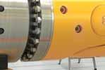
32 7 Engineering Basics 7.1 Major components of a Voith universal joint shaft Hub yoke, output end Welded yoke Tube Splined hub Flange yoke Journal cross Universal joint bearing Design 32


33 Irrespective of the series, all versions and sizes of Voith universal joint shafts share many of the same attributes designed to ensure reliable operation: Yokes and flange yokes with optimized geometry Drop-forged journal crosses Low-maintenance roller bearings with maximum load carrying capacity Use of high-strength tempered and case-hardened steels Superior welded joints Journal cross assembly Flange yoke Splined journal Welded yoke Dirt scraper Profile guard Shaft yoke, input end 33

 is a better solution for large high-performance universal joint shafts.")
34 1 2 1 SAE profile (straight flank profile) 2 Involute profile 7.2 Length compensation with spline shaft profi le Length compensation is required in the universal joint shaft for many applications. In comparison with other drive elements, length compensation for universal joint shafts is achieved through the center section and offset is achieved through the joints. For loads placed on smaller universal joint shafts, the involute profile is a suitable solution with a good cost / benefit ratio. The SAE profile (straight flank profile) is a better solution for large high-performance universal joint shafts. Two types of length compensation are utilized in Voith universal joint shafts: the SAE profile (straight flank profile) and the involute profile. The universal joint shaft series and size determine the type of length compensation. 34
35 Force introduced during torque transmission Torque transmission and centering Torque transmission Centering function F N F U F N > F U F U SAE profile (straight flank profile) Involute profile SAE profile (straight flank profile) Involute profile Spline Lubrication SAE profile (straight flank profile) Involute profile Length compensation with SAE profile (straight flank profile) Features Advantages Benefits Straight flank, diameter-centered profile Force is applied orthogonally Separation of torque transmission and centering functions Lower normal forces and thus lower displacement forces + Long service life + Ease of movement Large contact surfaces Low surface pressure + Long service life Favorable pairing of materials for hub and spline shaft Spline shaft nitrited as standard Patented lubricating mechanism in the grease distribution groove for uniform distribution of grease over the entire diameter of the profile High wear resistance Tooth shape incorporates lubricant res ervoir for reliable supply of lubricant to sliding surfaces + Long service life + Extended maintenance intervals 35

36 Tripod universal joint shaft 7.3 Length compensation with roller bearing tripod universal joint shafts Tripod universal joint shafts consist of standard joints with a special center section. Roller bearings in the center section are used to drastically reduce axial displacement forces in length compensation. This keeps axial displacement forces very low, almost constant, across the entire torque range. The center section consists of a guide shaft and a guide hub. Three bolts with roller bearings are located at one end of the guide shaft. The bolts are offset 120 from each other. The guide hub has three corresponding grooves to accept the roller bearings. Universal joint shafts of this type are ideal for drives that are required to constantly compensate wide axial movements. Basic design of the tripod universal joint shaft 36
37 Comparison of axial displacement forces F N Traditional universal joint shaft, profile design (sliding friction) Axial force F A Sliding friction F R,G v F N Rolling friction F R,R ω Tripod universal joint shaft with roller bearing (rolling friction) Input torque M d Length compensation with roller bearings Features Advantages Benefits Length compensation with roller bearings Low and virtually constant axial displacement forces Low-wear length compensation + Lower costs for axial bearings and suspension systems for connected assemblies + Low maintenance costs + High availability Hardened groove sides in guide hub Long service life Low wear No change in specified clearance + High availability + Low maintenance costs + No vibrations Uniform circumferential forces on all roller bearings Stable balancing over entire service life + No costs for rebalancing Sealed guide hub Secure roller bearing lubrication + Low service costs Defined, wide-support centering in roller and slide bushing planes Extremely smooth operation + Low noise emissions 37
38 RTR tripod l v øk ød l m l z Application examples In rail vehicles In ships and boats In paper machines 38
39 Size M z [knm] M DW [knm] I z min l v l m k d Dimensions in mm. Flange dimensions: Pages 20 to 23. Custom designs available on request. Advantages and benefits Tripod universal joint shafts transmit the torque from the drive motors to the drive wheels. The drive motors are located in the railcar body, the drive wheels in the spring-mounted bogie. + Small unsprung masses reduce the load on the bogie, drive, rails, and rail line + Positive travel (unobstructed sinusoidal pattern) minimizes the wear between rail and wheel + Good dynamic behavior increases safety and improves travel comfort Together with a highly flexible coupling, tripod universal joint shafts transmit the torque in the shaft line. + High degree of impact resistance + Structure-borne noise is well insulated + Improved travel comfort Tripod universal joint shafts in the drive of the Sirius Roll-up SensoRoll. + Smooth displacement of the SensoRoll in the direction of paper travel for every tambour + Drum has a hard wrapped core and a larger outer wrap diameter + Long uptime of the roller bearing length compensation 39
.")
40 7.4 Universal joint kinematics When the shaft is being driven uniformly W 1 (ω 1 = const.), the output shaft W 2 rotates at an angular velocity that changes over time (ω 2 const.). The angular velocity of the output shaft ω 2 and the differential angle φ = (α 1 α 2 ) vary in a sinusoidal manner and their magni tudes are a function of the deflection angle β. This characteristic of universal joints is called the gimbal error and must be taken into consideration when selecting a universal joint shaft. Universal joint α 1 G1 Standard universal joint W 1 W 2 Input shaft Output shaft W 1 G 1 α 2 α 1, α 2 β M 1, M 2 ω 1, ω 2 Angle of rotation Deflection angle Torques Angular velocities M 1, ω 1 β M 2, ω 2 W 2 40
41 Movement ratios β β β β β β = 12 φ β = 6 l φ maxl for β = β = 12 ω 2 ω β = 6 1 cos α 1 With one rotation of the shaft W 1, the differential angle φ changes four times, as does the angular velocity ω 2. During the course of one rotation, the shaft W 2 twice passes through the points of maximum acceleration and deceleration. At larger deflection angles β and higher velocities, considerable forces of inertia can be generated. The following equations apply: This yields the angular velocity ratio between shaft sections W 1 and W 2 : ω 2 cos β ω = (4) 1 sin 2 β sin 2 α 1 with the maximums ω 2 ω 1 = 1 max cos β at α 1 = 90 or α 1 = 270 and the minimums (4a) φ = α 1 α 2 (1) ω 2 ω 1 min = cos β at α 1 = 0 or α 1 = 180 (4b) tan α 1 = cos β (2) tan α 2 tan φ = tan α 1 (cos β 1) (3) 1 + cos β tan 2 α 1 As regards the torque ratio, the following equation applies: M 2 = ω 1 M ω (5) 1 2 with the maximums M 2 M 1 = 1 max cos β at α 1 = 90 or α 1 = 270 (5a) and the minimums M 2 M 1 min = cos β at α 1 = 0 or α 1 = 180 (5b) 41
42 Variation factor, differential angle Conclusions A single universal joint should only be used if the following conditions are met: The variation in the rotational speed of the output shaft is of secondary importance. The deflection angle is very small (β < 1 ). The forces transmitted are low. φ max φ max U 1.2 U β One indicator of the variation is the variation factor U: U = ω 2 ω 1 ω 2 max ω 1 = 1 cos β = tan β sin β (6) min cos β Finally, as regards the maximum differential angle φ max, the following equation applies: tan φ max = ± 1 cos β 2 cos β (7) 42

43 7.5 Double universal joint Section 7.4 shows that the output shaft W 2 always rotates at the varying angular velocity ω 2 when connected via a single universal joint at a given deflection angle β because of the influence of the universal joint. If, however, two universal joints G 1 and G 2 are connected together correctly in the form of a universal joint shaft in a Z or W arrangement, the variations in the speeds of the input and output shaft cancel each other completely. Universal joint shaft in Z arrangement, input and output shafts are located parallel to one another in one plane Universal joint shaft in W arrangement, input and output shafts intersect one another in one plane β 1 β 1 β 2 β 2 43


44 Conditions for synchronous rotation of input and output shafts: The three conditions A, B, and C ensure that joint G 2 operates with a phase shift of 90 and fully compensates for the gimbal error of joint G 1. This universal joint shaft arrangement is considered the ideal universal joint shaft arrangement, providing complete motion compensation. It is precisely what designers should be trying to achieve in practice. If any one of the three conditions is not met, then the universal joint shaft is no longer operating at constant input and output speeds, i.e., it is no longer homokinetic. When this happens, talk with your Voith representative. All of the components of the universal joint shaft are located in one plane Both yokes of the center section of the shaft are located in one plane G 1 G 1 A G 2 B G 2 The deflection angles β 1 and β 2 of the two joints are identical G 1 β 1 β 2 C G 2 44

 B 1 = M")
45 7.6 Bearing forces on input and output shafts Radial bearing forces The deflection of the universal joint shaft also subjects the connection bearings to radial loads. The radial forces on the bearings vary from no force to maximum force, twice per revolution. Designation and formulas G 1, G 2 Universal joints A, B, E, F Connection bearings M d Input torque A 1/2, B 1/2, E 1/2, F 1/2 Bearing forces α 1 Angle of rotation β 1, β 2 Deflection angles Maximum radial bearing forces with universal joint shafts in a Z arrangement a b L M d β 1 A B G 1 β 2 e f G 2 E F β 1 β 2 β 1 = β 2 α 1 = 0 B 1 F 1 A 1 E 1 A 1 = M d b cos β 1 (tan β L a 1 tan β 2 ) B 1 = M d (a + b) cos β 1 (tan β L a 1 tan β 2 ) E 1 = M d (e + f) cos β 1 (tan β L f 1 tan β 2 ) F 1 = M d e cos β 1 (tan β L f 1 tan β 2 ) A 1 = 0 B 1 = 0 E 1 = 0 F 1 = 0 α 1 = 90 A 2 F 2 A 2 = M d tan β 1 a B 2 = M d tan β 1 a A 2 = M d tan β 1 a B 2 = M d tan β 1 a B 2 E 2 sin β E 2 = M d 2 f cos β 1 sin β F 2 = M d 2 f cos β 1 E 2 = M d tan β 1 f F 2 = M d tan β 1 f 45
 B 1 = M d")
 sin β 1 L f F 1 = 2 M d e sin β 1 L f α 1 = 90 A 2 E 2 A 2 = M d tan β 1 a B 2 = M d tan β 1 a A 2 = M d tan β 1 a B 2 = M d tan β 1 a B 2 F 2 sin β E 2 = M d 2 f cos β 1 sin β F 2 = M d 2")
46 Designation and formulas G 1, G 2 Universal joints A, B, E, F Connection bearings M d Input torque A 1/2, B 1/2, E 1/2, F 1/2 Bearing forces α 1 Angle of rotation β 1, β 2 Deflection angles Maximum radial bearing forces on universal joint shafts in a W arrangement L a b β 1 β 2 e f M d G 1 G 2 A B E F β 1 β 2 β 1 = β 2 α 1 = 0 B 1 F 1 A 1 E 1 A 1 = M d b cos β 1 (tan β L a 1 tan β 2 ) B 1 = M d (a + b) cos β 1 (tan β L a 1 tan β 2 ) E 1 = M d (e + f) cos β 1 (tan β L f 1 tan β 2 ) F 1 = M d e cos β 1 (tan β L f 1 tan β 1 ) A 1 = 2 M d b sin β 1 L a B 1 = 2 M d (a + b) sin β 1 L a E 1 = 2 M d (e + f) sin β 1 L f F 1 = 2 M d e sin β 1 L f α 1 = 90 A 2 E 2 A 2 = M d tan β 1 a B 2 = M d tan β 1 a A 2 = M d tan β 1 a B 2 = M d tan β 1 a B 2 F 2 sin β E 2 = M d 2 f cos β 1 sin β F 2 = M d 2 f cos β 1 E 2 = M d tan β 1 f F 2 = M d tan β 1 f 46
47 7.6.2 Axial bearing forces In principle, the kinematics of a universal joint shaft do not generate any axial forces. However, axial forces that need to be absorbed by connection bearings do occur in universal joint shafts with length compensation for two reasons: 1. Force F ax, 1 as a result of friction in the length compensation As the length changes during the transmission of torque, friction is generated between the flanks of the profiles in the length compensation. For the frictional force F ax,1, which acts in an axial direction, the following applies: 2. Force F ax, 2 as a result of the pressure build-up in the length compensation during lubrication During the lubrication of the length compensation, an axial force F ax, 2 occurs as a function of the pressure applied while lubricating. Follow the information on this subject provided in the installation and operating instructions. F ax, 1 = μ M d 2 d m cos β where: μ Coefficient of friction; μ for steel on steel (lubricated) μ 0.07 for Rilsan plastic coating on steel μ 0.04 for PTFE coating on steel M d Input torque d m Pitch circle diameter of the profile β Deflection angle 47
48 7.7 Balancing universal joint shafts As with any other real body, the distribution of mass about the axis of rotation for a universal joint shaft is not uniform. This can lead to out-of-balance operation, which must be corrected on a case-by-case basis. Depending on the operating speed and the specific application, Voith universal joint shafts are dynamically balanced in two planes. Benefits of balancing: + Prevents vibrations, resulting in smoother operation + Longer universal joint shaft service life The balancing procedure used by Voith for universal joint shafts is based on the specifications in DIN ISO ("Mechanical vibration Balance quality requirements for rotors in a constant (rigid) state Part 1: Specification and verification of balance tolerances"). An extract from this standard lists the following approximate values for balance quality levels: Type of machine general examples Balance quality level G Complete piston engines for cars, trucks and locomotives G 100 Cars: Wheels, rims, wheel sets, universal joint shafts; crank drives with mass balancing on elastic mounts G 40 Agricultural machinery; crank drives with mass balancing on rigid mounts; grinders, mills and shredders; input shafts (cardan shafts, propeller shafts) Jet engines; centrifuges; electric motors and generators with a shaft height of at least 80 mm and a maximum rated speed of up to 950 rpm; electric motors with a shaft height of less than 80 mm; fans; gearboxes; general industrial machinery; machine tools; paper machines; process engineering equipment; pumps; turbochargers; hydro-power turbines Compressors; computer drives; electric motors and generators with a shaft height of at least 80 mm and a maximum rated speed over 950 rpm; gas turbines, steam turbines; machine tool drives; textile machinery G 16 G 6.3 G


49 1 2 1 Balancing machine 2 Balancing of universal joint shafts Depending on the application and maximum operating speed, balance quality levels for universal joint shafts are located in the range between G 40 and G 6.3. The reproducibility of mea surements may be subject to wider tolerances due to the influence of various physical factors. Such factors include: Design characteristics of the balancing machine Accuracy of the measurement method Tolerances in the connections to the universal joint shaft Radial and axial clearances in the universal joint bearings Deflection play in length compensation Grease distribution in the sliding area (Universal joint shafts were always balanced in non-greased condition) 49
50 8 Choosing a Solution How a universal joint shaft is designed depends on a number of factors. Using reliable calculations and testing will prevent hazardous situations in the surrounding area. Another factor to be considered is the costs that arise over the entire product life cycle. The design procedures described in this chapter are only intended to provide approximate guidelines. When making a final decision about a universal joint shaft, you can rely on our sales engineers for their technical knowledge and many years of experience. We will be happy to advise you. The following factors have a major influence upon any decision regarding universal joint shafts: Operating variables Main selection criterion: Bearing life or durability Installation space Connection bearings 50
![8.1 Defi nitions of operating variables Symbol Common unit Explanation P N [kw] Rated power of the drive motor n N [rpm] Rated speed of the drive motor M N [knm] Rated torque of the drive motor,](/docs-images/74/70222018/images/51-0.jpg "where: M N = 60 P 2π n N 9,55 P N N n N with M N in knm, n N in rpm and P N in kw M E [knm] Equivalent torque Equivalent torque is an important operating variable in cases where bearing life is the")
51 8.1 Defi nitions of operating variables Symbol Common unit Explanation P N [kw] Rated power of the drive motor n N [rpm] Rated speed of the drive motor M N [knm] Rated torque of the drive motor, where: M N = 60 P 2π n N 9,55 P N N n N with M N in knm, n N in rpm and P N in kw M E [knm] Equivalent torque Equivalent torque is an important operating variable in cases where bearing life is the main criterion in the selection of a universal joint shaft. It takes operating conditions into account and can be calculated for situations involving combined loads (see Section 8.2.1). If there is limited amount of available information on the operating conditions, the rated torque can be used as an initial estimate. n E [rpm] Equivalent speed Equivalent speed is an important operating variable in cases where bearing life is the main criteria in the selection of a universal joint shaft. It takes operating conditions into account and can be calculated for situations involving combined loads (see Section 8.2.1). If there is a limited information available on the operating conditions, the rated speed can be used as an initial estimate. M max [knm] Peak torque Peak torque is the maximum torque that occurs during normal operation. n max [rpm] Maximum speed Maximum speed is the highest speed that occurs during normal operation. n z1 [rpm] Maximum permissible speed as a function of the deflection angle during operation The center section of a universal joint shaft in a Z or W arrangement (β 0 ) does not rotate uniformly. It is subjected to a mass acceleration torque that depends upon the speed and the deflection angle. To ensure smooth operation and prevent excessive wear, the mass acceleration torque is limited by ensuring the maximum speed of the universal joint shaft n z1 is not exceeded. To learn more, see Section n z2 [rpm] Maximum permissible speed taking bending vibrations into account A universal joint shaft is an elastic body when bending. At a critical bending speed (whirling speed), the frequency of the bending vibrations equals the natural frequency of the universal joint shaft. The result is high loading on all of the universal joint shaft components. The maximum speed of the universal joint shaft must be significantly lower than this critical speed. To learn more, see Section β [ ] Deflection angle during operation Deflection angle of the two joints in a Z or W arrangement, where: β = β 1 = β 2 If three-dimensional deflection is present, the resultant deflection anglel β R is determined as follows: tan β R = tan 2 β h + tan 2 β V where: β = β R β v1 β v2 β h1 β h2 51
52 8.2 Size selection There are essentially two selection criteria when choosing the size of a universal joint shaft: 1. Service life of the roller bearings in the joints 2. Operational durability, including torque capacity and/or load limit As a rule, the application determines the primary selection criterion. A selection based upon bearing life is usually made in cases where drives require a long service life and pronounced torque spikes never occur or happen only briefly (for instance, during start-up). Typical examples include drives in paper machi nery, pumps and fans. In all other applications, the selection is made on the basis of operational durability Selection based upon bearing life The procedure used for calculating the bearing life is based upon the specifications in DIN ISO 281 ("Roller bearings Dynamic load ratings and nominal service life"). However, this standard fails to take a number of factors into account when applied to universal joint shafts; for instance, the support of the bearings, i.e., deformation of the bore under load. Up to now, it has only been possible to assess these factors qualitatively. The theoretical bearing life in a universal joint shaft can be calculated using the following equation: 1,5 107 L h = n E β K B ( CR M E ) 10 3 where: L h is the theoretical bearing life in hours [h] CR Load rating of the universal joint in knm (see tables in Section 6) β Deflection angle in degrees [ ]; in the case of threedimensional deflection, the resulting deflection angle β R is used; in any case, however, a minimum angle of 2 must be applied K B Operational factor n E Equivalent speed in rpm M E Equivalent torque in knm Operational factor Torque spikes occur in drives with diesel engines that can be accounted for using the operational factor K B : Driving machine Operational factor K B Electric motor 1 Diesel engine
53 Equivalent operating values The equation for the theoretical bearing life assumes a constant load and speed. If the load changes in increments, the equivalent operating values can be determined that produce the same bearing fatigue as the actual loads. The equivalent operating values are ultimately the equivalent speed n E and the equivalent torque M E. If a universal joint shaft transmits the torque M i for a time period T i at a speed of n i, then the first task is to define a time segment q i that normalizes the time period T i with respect to the overall duration of operation T ges : Conclusions The calculated bearing life is a theoretical value that is usually significantly exceeded in practice. The following additional factors affect the bearing life, sometimes to a significant degree: Quality of the bearings Quality (hardness) of the journals Lubrication Overloading that results in plastic deformation Quality of the seals q i = T i T ges u where q i = q 1 + q q u = 1 i = 1 Using this, the equivalent operating values can be determined: u n E = q i n i = q 1 n 1 + q 2 n q u n u i = 1 u ( ) q i n i M i i = 1 M E = n E ( ) q 1 n 1 M 3 + q 1 2 n 2 M q u n u M u = n E 3 10 Incremental variation of the load on a universal joint shaft M, n M 1 M u M 2 n 1 n 2 n u 0 q 1 q 2 q u 1 q 53
54 8.2.2 Making a choice based on operational durability Operational durability calculations can be made using a load spectrum. In practice, however, sufficiently accurate load spectra are seldom available. In cases like this, we are forced to fall back on the quasi-static dimensioning procedure. With this approach, the expected peak torque M max is compared with the torques M DW, M DS and M Z (see Section 5.2). The following estimate applies for peak torque: M max K 3 M N K 3 is called the shock factor. These are empirical values based upon decades of experience in designing universal joint shafts. The peak torque determined in this manner must meet the following requirements: 1. M max M DW for alternating load 2. M max M DS for pulsating load 3. Individual and rarely occurring torque spikes must not exceed the value M Z. The permissible duration and frequency of these torque spikes depends upon the application; please contact Voith for more information. Shock load Shock factor K 3 Typical driven machinery Minimal Generators (under a uniform load) Centrifugal pumps Conveying equipment (under a uniform load) Machine tools Woodworking machinery Moderate Multi-cylinder compressors Multi-cylinder piston pumps Light-section rolling mills Continuous wire rolling mills Primary drives in locomotives and other rail vehicles Severe 2 3 Transport roller tables Continuous pipe mills Continuously operating main roller tables Medium-section rolling mills Single-cylinder compressors Single-cylinder piston pumps Fans Mixers Excavators Bending machines Presses Rotary drilling and boring equipment Secondary drives in locomotives and other rail vehicles Very severe 3 5 Reversing main roller tables Coiler drives Scale breakers Cogging/roughing stands Extremely severe 6 15 Roll stand drives Plate shears Coiler pressure rolls 54
55 8.3 Operating speeds Maximum permissible speed n z1 as a function of the deflection angle Section 7.4 shows that a universal joint exhibits a varying output motion. A universal joint shaft is a connection of two universal joints in series with one another. Under the conditions described in Section 7.5, a universal joint shaft in a Z or W arrangement exhibits homokinetic motion between the input and output. Nevertheless, the center section of the universal joint shaft still rotates at the periodically varying angular velocity ω 2. In addition, the mass acceleration torque can affect the entire driveline on universal joint shafts with length compensation, as well as universal joint shafts without length compensation. One example of this is torsional vibrations. These adverse effects can be prevented by ensuring that the following conditions are met: n max n z1 The center section of the universal joint shaft exhibits a mass moment of inertia, thus creating a moment of resistance to the angular acceleration dω 2 / dt. On universal joint shafts with length compensation, this alternating mass acceleration moment can cause clattering sounds in the profile. The consequences include less smooth operation and increased wear. Approximate values of n z1 as a function of β R R S S S S S S S S S S S S n z1 [rpm] R CH R CH R CH R CH R CH R R R β [ ] 55
56 8.3.2 Maximum permissible speed n z2 as a function of operating length Every universal joint shaft has a critical bending speed (whirling speed) at which the frequency of the bending vibrations reaches the natural frequency of the shaft. The result is high loading on all components of the universal joint shaft, leading to the possibility of it being damaged or destroyed in adverse situations. Calculating this critical bending speed for a real universal joint shaft in a driveline is a complex task Voith uses numerical computing programs to ensure the accuracy of the calculations. For safety reasons and to prevent the failure of the universal joint shaft, please ensure the following condition is met: n max n z2 For normal connecting and operating conditions, it is possible to specify approximate values for the maximum permissible speeds n z2 as a function of operating length l B : The critical bending speed depends essentially upon three factors: Operating length l B Deflection resistance of the universal joint shaft Connecting conditions at the input and output ends The maximum permissible speed n z2 is determined in such a way that provides a safety allowance with respect to the critical bending speed that is suitable for the particular application. 56
57 Approximate values of n z2 as a function of l B for the S Series S S S n z2 [rpm] S S S S S S S S S I B [mm] Approximate values of n z2 as a function of l B for the R and CH Series R R R R R R CH R CH R CH R CH R CH n z2 [rpm] I B [mm] 57
58 8.4 Masses Size Tube values based on length Universal joint shafts with length compensation m' R [kg / m] m L min [kg] m L min [kg] m L min [kg] m L min [kg] m L min [kg] ST / STL / SF ST STL STK1 STK2 STK Values available on request RT / RTL / RF RT RTL RTK1 RTK Values for dimensions and series not listed are available on request. Symbol m' R Explanation Mass of the tube per 1 m of length Universal joint shafts with length compensation m L min Mass of the universal joint shaft for a length of l z min Calculations for the entire universal joint shaft: m ges Total mass m ges = m L min + (l z l z min ) m' R 58
59 m L min [kg] Universal joint shafts without length compensation m L min [kg] Joint coupling m L fix [kg] STK4 SF SGK RF RGK Universal joint shafts without length compensation l min m ges = m L min + (l l min ) m' R 59
60 8.5 Connection fl anges and bolted connections When installing Voith universal joint shafts in a driveline, the connection flanges and bolted connections must satisfy a number of requirements: 1. Design When using a universal joint shaft without length compensation, a connection flange ("wobbler") that is movable in a longitudinal direction is required so that the universal joint shaft can slide over the spigot. The connection flange also absorbs other changes in length, for instance, due to thermal expansion or changes in the deflection angle. 2. Material The connection flange material is designed for use with strength class 10.9 bolts (per ISO 4014 / 4017 or DIN ). Special case for the S and R Series: If the material used for the connection flanges does not per mit the use of bolts of strength class 10.9, the torques that can be transmitted by the flange connection are reduced. The specified tightening torques for the bolts must be reduced accordingly. 3. Dimensions, bolted connections On universal joint shafts of the S and R Series, the di mensions of the connection flanges must match those of the universal joint shaft, except for the spigot diameter c. The spigot diameter includes clearance (fit H7 / h6). On universal joint shafts with an H flange, the dimensions of the connection flanges are identical to those of the universal joint shaft. The Hirth couplings are self-centering. On S and R Series universal joint shafts, the relief diameter f g on the universal joint shaft flange is not suitable for locking hex head bolts or nuts. A relief diameter f a on the connection flange is suitable for this purpose. 60
61 Flange connection for universal joint shafts of the S and R Series A B A m min Z 1 m g g v n o p m min Z 1 m g g v Z 2 t y a x øa øf a øc øf g øb øa øf a øf g øb S flange / Q flange K flange H flange Fastener hole pattern for flange connections on the S and R Series of universal joint shafts A+B A A A A 8 x A 4 x B B A 4 x A A 8 x A A A A 12 x A A A A 10 x A 4 x B A 6 x A 10 x A A 16 x A A A 36 A B A 60 A A 36 A A A 22.5 A 61
62 Connection flange dimensions Bolted connection (A) Remarks Size a b ±0.1 c H7 f a -0.3 f g g t v x P9 y a +0.5 Z 1, Z 2 z z z m Bolt S flange / K flange M5 x M6 x M6 x M8 x M8 x M10 x M10 x M12 x M12 x M12 x M14 x M16 x M16 x M18 x M20 x M22 x M22 x M24 x M27 x 120 Q flange M16 x M18 x M20 x M22 x M22 x M24 x M27 x M30 x M30 x 140 H flange M16 x M18 x M20 x M22 x M22 x M24 x M27 x M30 x M30 x 140 Dimensions in mm. 62
63 Bolted connection with split sleeve (B) Symbol Explanation Remarks Additional information a Flange diameter M A [Nm] EB z n Bolt o Sleeve p Washer M A [Nm] b c Bolt circle diameter Spigot diameter 7 No 13 No 13 No 31 No 31 No 63 No 63 No 109 No 109 No 109 No 175 No 265 No 4 M12 x x Yes 4 M12 x x No 4 M14 x x No 4 M16 x x Yes 4 M16 x x Yes 4 M18 x x No 4 M18 x x No 4 M20 x x No 365 No 515 No 695 No 695 No 890 No No No No 265 No 365 No 515 No 695 No 695 No 890 No No No No f a f g g t v Flange diameter, bolt side Flange diameter, nut side Flange thickness Spigot depth in connection flange Length from the contact surface of the nut to the end of the hexagon head bolt x Width of face key in universal joint shaft connection flanges with a face key y a Depth of face key in universal joint shaft connection flanges with a face key Z 1 Axial run-out 1 Permissible values for deviation Z 2 Concentricity in axial runout Z 1 and con centricity Z 2 at operating speeds below rpm. At operating speeds of rpm to rpm, reduce the values by half! m ISO 4014 / or DIN hex head bolt with DIN hex nut m min Minimum length for the installation of bolts 2 z each per standard connection flange 3 z each per connection flange with face key 4 z each per connection flange with Hirth coupling 5 Dimension of hexagon head bolt with nut 6 Tightening torque for a coefficient of friction μ = 0.12 and 90 % utilization of the bolt yield utilization of the bolt yield point Length of the hexagon head bolt m including the height of the bolt head EB Insertion options 7 Bolts are inserted from the joint side; if hex head bolts cannot be inserted from the joint side or the connection flange side, studs must be used n ISO 4014 / or DIN hex head bolt with DIN hex nut 8 z each per connection flange 9 Dimension of hexagon head bolt with nut 12 Tightening torque for a coefficient of friction μ = 0.12 and 90 % utilization of the bolt yield utilization of the bolt yield point o Split sleeve 10 Outer diameter x length of the split sleeve [mm x mm] p Washer 11 Washer interior diameter [mm] 63

64 Universal Joint Service Center in China Offices worldwide Heidenheim Office Sales Offices Service Centers 64
65 9 Service For us, service means quality and dependability that exceeds the expectations of our customers. We stand by you, anywhere in the world, for the entire service life of your system. You can count on us, from planning and commissioning to main tenance. Voith's Universal Joint Shaft Service will increase the availability and service life of your system. Voith Universal Joint Shaft Service Consulting and engineering Pre-sales After-sales Installation Commissioning Original spare parts' supply Overhaul Repairs Modernizations, retrofits Torque measurements (ACIDA) Training Torsional vibration simulations 65


66 9.1 Installation and commissioning Correct installation of a universal joint shaft is a must for trouble-free commissioning. A systematic commissioning procedure with extensive operational testing is an important factor in achieving maximum reliability and a long operational life for your universal joint shaft and the system as a whole. What we offer Installation and commissioning by our service experts Training for operating and maintenance personnel Your benefits + Immediate access to expert know-how during the entire start-up phase + Assurance of trouble-free and professional commissioning for your universal joint shaft 66


67 9.2 Training Efficiency, reliability and availability are essential factors in ensuring the success of your system. This requires having the best-trained employees in technology and servicing. Initial and ongoing training are indispensable investments that will ensure the efficient operation of your universal joint shafts. What we offer Product training at Voith or on-site at your location Theoretical and practical maintenance and repair training Our training programs arm your staff with specific technical knowledge about our products. Your staff will be up to speed with the latest Voith technology in theory and in practice. Your benefits + Safer use of Voith products + Prevention of operating and maintenance errors + Better understanding of Voith technology in the driveline 67


68 9.3 Voith original spare parts Using original spare and wear parts will help reduce operating risk. Only original parts are manufactured with Voith knowhow and can guarantee reliable and safe operation of your Voith products. High availability and efficient logistics guarantee quick delivery of parts around the world. What we offer Most original spare and wear parts warehoused at our service branches Same-day shipment of in-stock parts (for orders received by 11 a.m.) Consultation with your spare parts management staff Preparation of project-specific spare and wear parts packages Spare parts also available for older generations of Voith universal joint shafts Your benefits + Safe and reliable operation of all components + The highest quality parts that fit exactly + Maximum service life of drive elements + Manufacturer's warranty + High degree of system availability + Fast spare parts delivery Journal crosses Flange yokes 68


69 9.4 Overhaul and maintenance Constant operation subjects universal joint shafts to natural wear, which is also influenced by the environment. Regular professional overhauls of your universal joint shaft will prevent damage and reduce the risk of expensive production downtimes. You get operational reliability while saving money in the long term. What we offer Maintenance or complete overhaul by our service experts with all the special tools and fixtures necessary Use of original spare and wear parts Consultation regarding your maintenance strategy Your benefits + The security that professional maintenance provides + Manufacturer's warranty + Increased system availability 69

70 9.5 Repairs and reconditioning Even the best preventive maintenance cannot rule out unplanned downtime due to equipment failure. When this happens, the priority is to repair the components and equipment as quickly as possible. As the manufacturer, we not only have a wealth of knowledge about universal joint shafts, but we also possess the necessary technical competence, experience, and tools to ensure professional and speedy repair. Our service technicians can quickly assess damage and provide suggestions for rapid correction. What we offer Fast and professional repairs that meet our safety standards on-site at your location or at one of our certified Voith Service Centers around the world Experienced damage assessment, including vulnerability analysis Fast delivery of original spare parts Your benefits + The security that a proper repair provides + Manufacturer's warranty + The shortest possible outage and downtime + Prevention of repeat outages or malfunctions 70

71 9.6 Modernizations and retrofi ts Technology is continually advancing, which means that the original requirements on which the design of a system was based could change over time. Voith can help you realize significant improvements in efficiency and reliability through a tailored upgrade or retrofit of your old drive elements, e.g., slipper spindles. We analyze, advise, and upgrade universal joint shafts including connection components in order to keep you equipped with the latest and most economical technology. What we offer Modification or redesign of your universal joint shafts and connection components Competent consultation regarding modernization opportunities, including the design of the driveline Your benefits + Improved reliability, availability and affordability of your drive system + Reduced operating costs + A universal joint shaft that features the latest technology 71

72 9.7 Health Check In order to be able to assess the condition of your plant and your foundations as accurately as possible, the Health Check should be carried out at regular intervals and under comparable conditions. With our Health Check, you increase the availability and lifetime of your system. What we offer Visual inspection Middle part: Visual crack test of critical areas, if necessary Check condition of joints Visual crack test at the flange Check condition of the bearings. Check condition of grease. Check the condition of roll end sleeve, dimensional test and visual crack test Check the tightening torques of flange connection bolts Check the Hirth coupling seal Regreasing the joints and the sliding area (if shaft has length compensation) Check condition of spare shafts in stock Recommendations Example: Visual crack test at the flange yokes Your benefits Visual crack test areas in red high loaded areas. If necessary additional dye-penetration test. + The above inspection procedures will provide you with a clear assessment as to the condition of your installed universal joint shafts. Risk of failures is minimized. + Expert advice directly from the manufacturer + Visual assessment on the basis of manufacturer know-how + Competence and experience in diagnosing + Close cooperation between operator and manufacturer + Continuous information about the latest technical state of our products + Regular Health Checks minimize the risk of costly production downtimes. 72
73 73


74 10 Services and Accessories 10.1 Engineering We deliver not just products but ideas, too! Reap the benefit of our many years of engineering know-how in all matters related to projects involving complete drivelines, from design calculations, installation and commissioning, to questions about cost-optimized operation and maintenance concepts. Engineering services Preparation of specifications Preparation of project-specific drawings Torsional and bending vibration calculations Design and sizing of universal joint shafts and connecting components Clarification of special requirements from the operator Preparation of installation and maintenance instructions Documentation and certifications Special acceptance tests conducted by classifying and certifying agencies Special universal joint shafts Designing special universal joint shafts to match your drive and your operating conditions is just one of the regular en gineering services we offer. This includes: Any necessary design work Strength tests and optimization of the designs using FEM analysis Dynamic testing to ensure maximum reliability Designing a driveline using CAD FEM analysis of a work roll, with a split wobbler (illustration: roll journal and wobbler) 74


75 10.2 Connection components for universal joint shafts Drive systems require reliable transmission of torque by the input and output connection component on the universal joint shaft, e.g.: Wobbler Connection flanges Adapter flanges Adapters Applications Features Rolling mills Paper machines Pumps General mechanical engineering Test rigs Construction machinery and cranes Individual adaptation to all adjoining components Precision manufacturing through the use of state-of-the-art machining centers Transmission of maximum torque through the use of highquality materials High level of wear resistance through hardened contact surfaces Rolling mill connection components for connecting universal joint shafts with work rolls ('wobbler') 75


76 10.3 Quick-release GT coupling The quick-release GT coupling is designed to be a very effective connection component. The GT coupling allows you to rapidly assemble and disassemble a wide range of shaft connections in your machine, which in turn significantly reduces the amount of required downtime associated with main tenance and repair. Applications Features Drives that require quick and precisely centered replacement of coupling connections, e.g., universal joint shafts and disk couplings Roll and cylinder connections, e.g., in paper machines Positive transmission of torque through claw serrations Quick and easy assembly/disassembly Compact design Only two major components Stainless steel version available Schematic diagram of the GT quick-release coupling Universal joint shaft with ring of the GT quick-release coupling 76
 Machine tools Turbo compressors Metrology")
77 10.4 Voith Hirth coupling The Voith Hirth coupling transmits maximum torque at the specified diameter. Applications Features Universal joint shafts with high torque requirements Connecting flange for universal joint shafts (also can be provided by customer) Machine tools Turbo compressors Metrology Robotic equipment Nuclear technology Medical equipment General mechanical engineering High level of torque transmission, as angular surfaces provide positive locking transmission of most of the peripheral forces. Only a small axial force needs to be absorbed by the bolts Self-centering through use of optimized tooth geometry High wear resistance due to the high load-bearing per centage of the tooth profile Excellent repeatable accuracy as a result of the multiple wedge design positive locking indexing accuracy self-centering F a Fu Universal joint shaft with Hirth coupling on the end flange faces Primary functions of the Hirth coupling 77

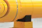
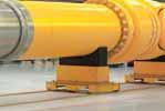
78 10.5 Universal joint shaft support systems Positioning and supporting a universal joint shaft and its wobbler and connection flanges requires a support mechanism. Applications Features Rolling mills Customer-specific drives Increased productivity and system availability as a result of significantly reduced maintenance downtime Reduced energy and lubricant costs as well as higher transmission efficiency through the use of roller bearings Reduced wear thanks to uniform power transmission Universal joint shaft support (red) and coupling support (yellow) 78

79 10.6 Universal joint shafts with carbon fi ber-reinforced polymer (CFRP) Universal joint shafts that use CFRP components increase the efficiency and performance of machines and systems. The use of CFRP in universal joint shaft design reduces masses, vibrations, deformations and energy consumption. We offer not only the drive engineering know-how, but also the production know-how for CFRP components all from a single source. Applications Features Long drivelines with no intermediate bearings Drives with low mass Drives with optimized vibration behavior Pumps Ships and boats Rail vehicles General mechanical engineering Depending on the requirements, universal joint shafts with carbon tube or solid-carbon center section Lower loads thanks to low masses Extremely smooth operation and low vibration wear due to high rigidity Low acceleration and deceleration torques due to low moment of inertia Universal joint shaft with carbon-fiber tube 79


80 Voith WearCare 500 in 45 kg and 180 kg drums 10.7 High-performance lubricant for universal joint shafts Voith development engineers have combined their universal joint shaft know-how with the tribology know-how of renowned bearing and lubricant manufacturers. The result of this coopera tion is an innovative and exclusive lubricant with properties that far exceed those of conventional lubricants. This lubricant gives bearings in universal joint shafts operating at low speeds and under high loads an even longer service life. In addition, lubrication intervals can be extended and emer gency dry-running characteristics are improved sig nificantly. 80
81 Characteristics of Voith's WearCare 500 high-performance lubricant Optimum adhesion and surface wetting Exceptional corrosion protection Maximum ability to withstand pressure Optimum and long-lasting lubricating action Can be mixed with lithium-based greases High resistance to aging Excellent compatibility with all bearing components Contains no silicone and copper-based ingredients Advantages + Lubricating film even in the event of underlubrication + Formulated for oscillating bearing motion + Ideal for rolling mills + Hydrodynamic lubricating film even under maximum torque conditions + Minimal abrasive wear in the bearing + Extended lubrication intervals + Lower maintenance costs + Simple conversion to Voith's high-performance lubricant + Long shelf life + No softening of bearing seals + Does not corrode nonferrous metals + Suitable for aluminum rolling mills Field trial Metal particles in the bearing lubricant of a high-performance universal joint shaft used in a rolling mill drive FE8 test rig trial Bearing wear in an axial cylindrical roller bearing Relative metal particles in the lubricant Reference wear condition Standard lubricant Voith WearCare 500 Extended operating time Relative bearing wear 15 Standard lubricant Voith WearCare Operating time in months 81
 against damage.")
82 10.8 SafeSet torque limiting safety couplings The SafeSet coupling is a torque limiting safety coupling that instantaneously disengages the force flow of the driveline in the event of a potentially catastrophic torque overload event, thus protecting all of the drive components in the driveline (motors, gearboxes, universal joint shafts, etc.) against damage. By integrating the SafeSet safety coupling into the universal joint shaft, Voith's proprietary 'integral design' reduces the deflection angle of the universal joints, thus increasing the bearing life. Applications Features Protects the driveline from potentially damaging overload torques Rolling mills Shredders Cement mills Sugar mills Rail vehicle drives Adjustable release torque Release torque does not change over time Backlash-free power transmission Compact, lightweight design Low mass moment of inertia Minimal maintenance required Three-dimensional view through a SafeSet safety coupling (type SR-C) Torque-limiting SafeSet safety coupling (blue) integrated into a Voith high-performance universal joint shaft 82

83 10.9 ACIDA torque monitoring systems ACIDA torque monitoring systems have proven their worth in accurately measuring dynamics in universal joint shafts. Being able to directly measure the actual, mechanical drive load provides important information for process monitoring and plant optimization. Analysis modules, for instance load spectra or ser vice life monitoring, have been specially developed for extremely heavy-duty drives and unusually severe load conditions. Additional options include online vibration diag nosis for gearboxes and roller bearings. Applications Features Torque monitoring Vibration monitoring Process optimization Condition-based maintenance Reference systems: Rolling mills, cement mills, briquetting plants, agitators, conveying equipment, ship propulsion systems, locomotives, paper machines, mining, etc. Permanent or temporary torque sensors Complete monitoring systems, including hardware and software Report generator with automatic analysis, alarm signaling and reporting Remote service with expert support Non-contact torque monitoring system The ACIDA monitoring system in comparison Torque [Nm] Time [s] 1 Rotor: Strain gauges and telemetry (requires no drive modifi cations) 2 Air gap: No contact between rotor and stator 3 Stator: Signal reception and inductive power supply Bright blue: The ACIDA monitoring system measures torques and dynamics with extreme accuracy and high dynamic response. Dark blue: Conventional systems measure motor current or hydraulic pressure, for example, with insuffi cient signal dynamics. 83

84 1 11 Integrated Management System At Voith, ensuring the affordability, reliability, environmental compatibility and safety of our products and services is our top priority. In order to maintain these principles now and in the future, Voith has implemented a solid, integrated management system focused on quality, the environment, and occupational health and safety. Our customers know that this means they are acquiring high-quality capital goods that are being manufactured and used under safe working and environmental conditions. 84

85 2 1 ISO 9001 certificates for management systems: 2000 (quality), ISO 14001: 2000 (environment) and OHSAS 18001: 1999 (occupational health and safety) 2 Flange yoke for a high-performance universal joint shaft on a 3-D coordinate measuring machine 11.1 Quality We employ state-of-the-art 3-D coordinate measuring machines for quality assurance. To ensure perfectly welded joints, we conduct x-ray inspections in-house. We offer our customers a variety of product-specific and application-specific certifications and classifications. Production and assembly fixtures are inspected on a regular basis. Quality-relevant measuring and testing instruments are subject to systematic monitoring. Process qualifications per ISO are available for the welding methods employed. Welding technicians are EN 287-qualified and our welding equipment is con tinuously monitored. Employees that perform nondestructive testing are ASNT-C-1A and / or EN 473-qualified. 85

86 Environment Voith universal joint shafts are fitted with sealed roller bearings. These offer two major benefits over slipper and gear type spindles: 1. Lubricant consumption is considerably lower because of the seals. 2. Efficiency is enhanced, as rolling friction is significantly lower than sliding friction. This translates into reduced CO 2 emissions and protects the environment. Efficiency and power loss in the main drive of a rolling mill % 71.1 kw Input power kw, deflection angle % 41.1 kw Efficiency Power loss 0.32 kw Voith universal joint shaft Gear spindle % Slipper spindle 86

87 2 1 An employee coats the roller bearing of a universal joint shaft with Voith WearCare 500 high-performance lubricant 2 Voith universal joint shafts receive their final finish in a modern paint booth 11.3 Occupational health and safety Voith painting technicians use a modern painting system when painting the universal joint shafts that meets all of the requirements for health and safety for occupational and environmental protection. Electrostatic application of the paint reduces overspray. An exhaust system extracts any residual mist. An exhaust air treatment system with combined heat recovery reduces the impact on employees and the environment. 87
High-Performance Universal Joint Shafts Products Engineering Service
 High-Performance Universal Joint Shafts Products Engineering Service Universal Joint Shafts and Hirth Couplings We are the experts for cardanic power transmission components and Hirth couplings within
Driveshafts for Industrial Applications
 Driveshafts for Industrial Applications Table of Contents 1 Dana: Driveshaft engineering experts 4 Survey of GWB TM driveshaft series with design features and preferred applications 8 Special designs of
RIGIFLEX -N RADEX -N. Steel laminae coupling. Steel laminae coupling. You will find continuously updated data in our online catalogue at
 117 Table of contents 117 Coupling selection steel laminae coupling 119 Description of coupling 121 General information 122 Types and applications 123 Technical data 124 Standard types 126 Special types
PRECISION BELLOWS COUPLINGS
 PRECISION BELLOWS COUPLINGS Bellows couplings are used where precise rotation, high speeds, and dynamic motion must be transmitted. They exhibit zero backlash and a high level of torsional stiffness, offering
Series 54 and S54 Resilient Couplings
 Series 54 and S54 Resilient s Bibby Transmissions Resilient s Bibby are the world originator of the resilient grid type shaft coupling, which is universally accepted by engineers to be one of the most
Heavy-Duty Rod Ends - Male with integral spherical plain bearing
 Heavy-Duty Rod Ends - Male with integral spherical plain bearing 65700 Order No. Thread (hand) d 1 l 1 d 2 d 3 d 4 l 2 l 3 X g H7 65700.W0005 Right 5 33 M 5 11,11 18 20 9 14 65700.W0006 Right 6 36 M 6
...our linkages, your solution. Rod Ends
 ...our linkages, your solution Technical Information Introduction All of our rod ends incorporate either a plain spherical bearing, ball bearing, or roller bearing. Below is an overview of each type. Plain
Torsional Vibrations under Control. Highly Flexible Couplings
 Torsional Vibrations under Control. Highly Flexible Couplings 1 Experts for a Reliable Connection Manufacturers and operators always have big expectations regarding the productivity of their vehicles and
Chapter 11. Keys, Couplings and Seals. Keys. Parallel Keys
 Chapter 11 Keys, Couplings and Seals Material taken for Keys A key is a machinery component that provides a torque transmitting link between two power-transmitting elements. The most common types of keys
2. Motion relationships and torques
 2. Motion relationships and torques 2.1 Rotation angle of a single joint as a function of defl ection angle ß 1 Input rotation angle 2 Output rotation angle If a single joint is deflected by angle ß and
Shaft Couplings Flange-Couplings Rigid Shaft Couplings Flexible Couplings
 Shaft Couplings Flange-Couplings Rigid Shaft Couplings Flexible Couplings 44 Edition 2013/2014 RINGSPANN Registered Trademark of RINGSPANN GmbH, Bad Homburg 2 Table of Contents Flange-Couplings Page Flange-Couplings
Solutions In Motion SM. Power Transmission Group. Universal Driveshaft Technology for Heavy Duty Industrial Applications
 Solutions In Motion SM Power Transmission Group Universal Driveshaft Technology for Heavy Duty Industrial Applications Universal Driveshaft Technology for Heavy Duty Industrial Applications Our Experience
Ball Rail Systems RE / The Drive & Control Company
 Ball Rail Systems RE 82 202/2002-12 The Drive & Control Company Rexroth Linear Motion Technology Ball Rail Systems Roller Rail Systems Standard Ball Rail Systems Super Ball Rail Systems Ball Rail Systems
Profi le rail guides LLR
 Profi le rail guides LLR Content The SKF brand now stands for more than ever before, and means more to you as a valued customer. While SKF maintains its leadership as the hallmark of quality bearings throughout
Assemblies for Parallel Kinematics. Frank Dürschmied. INA reprint from Werkstatt und Betrieb Vol. No. 5, May 1999 Carl Hanser Verlag, München
 Assemblies for Parallel Kinematics Frank Dürschmied INA reprint from Werkstatt und Betrieb Vol. No. 5, May 1999 Carl Hanser Verlag, München Assemblies for Parallel Kinematics Frank Dürschmied Joints and
EMC-HD. C 01_2 Subheadline_15pt/7.2mm
 C Electromechanical 01_1 Headline_36pt/14.4mm Cylinder EMC-HD C 01_2 Subheadline_15pt/7.2mm 2 Elektromechanischer Zylinder EMC-HD Short product name Example: EMC 085 HD 1 System = ElectroMechanical Cylinder
In-house development Own manufacturing Sole distributor in Germany Working with distributors worldwide
 In-house development Own manufacturing Sole distributor in Germany Working with distributors worldwide External Clamping devices Overview 3073 Mini-Range For very low torque transmission Very small profile
GEAR-COUPLINGS. Series LX GLX S-NX
 GEAR-COUPLINGS Series LX GLX S-NX CONTENTS Application 3 Quality and production 3 Design and characteristics 3 selection 4-5 Key connections 6 Shrink-fit connections 7 Standard design with one-piece housing
Coupling description. Disc pack with bolts
 Coupling description RADEX -N couplings are designed to transmit torque between drive and driven components via steel hubs and flexible metallic elements commonly known as discs. The combination of these
LESSON Transmission of Power Introduction
 LESSON 3 3.0 Transmission of Power 3.0.1 Introduction Earlier in our previous course units in Agricultural and Biosystems Engineering, we introduced ourselves to the concept of support and process systems
alpha Value Line - NPS Sizing and Technical Data Efficient Flexible Reliable
 alpha Value Line - NPS Sizing and Technical Data Efficient Flexible Reliable alpha Value Line NP NPS NPL NPT NPR Ratios 3-100 Torsional backlash [arcmin] 8 Output type Smooth output shaft Grooved output
TRANSLATION (OR LINEAR)
") 5) Load Bearing Mechanisms Load bearing mechanisms are the structural backbone of any linear / rotary motion system, and are a critical consideration. This section will introduce most of the more common
5) Load Bearing Mechanisms Load bearing mechanisms are the structural backbone of any linear / rotary motion system, and are a critical consideration. This section will introduce most of the more common
DESIGN OF MACHINE ELEMENTS UNIVERSITY QUESTION BANK WITH ANSWERS. Unit 1 STEADY STRESSES AND VARIABLE STRESSES IN MACHINE MEMBERS
 DESIGN OF MACHINE ELEMENTS UNIVERSITY QUESTION BANK WITH ANSWERS Unit 1 STEADY STRESSES AND VARIABLE STRESSES IN MACHINE MEMBERS 1.Define factor of safety. Factor of safety (FOS) is defined as the ratio
Torque Limiting Couplings Reliable Energy Production
 Torque Limiting Couplings Reliable Energy Production 1 The Challenges in Energy Extraction Energy extraction from natural resources can be quite unpredictable. To be effective you need to be able to control
Features of the LM Guide
 Features of the Functions Required for Linear Guide Surface Large permissible load Highly rigid in all directions High positioning repeatability Running accuracy can be obtained easily High accuracy can
R310EN 2302 ( ) The Drive & Control Company
 The Drive & Control Company") R31EN 232 (26.4) The Drive & Control Company Bosch Rexroth AG Linear Motion and Assembly Technologies Ball Rail Systems Linear Bushings and Shafts Ball Screw Drives Linear Motion Systems Basic Mechanical
R31EN 232 (26.4) The Drive & Control Company Bosch Rexroth AG Linear Motion and Assembly Technologies Ball Rail Systems Linear Bushings and Shafts Ball Screw Drives Linear Motion Systems Basic Mechanical
Shaft Couplings Tru-Line Flange-Couplings Rigid Shaft Couplings Flexible Couplings
 Shaft Couplings Tru-Line Flange-Couplings Rigid Shaft Couplings Flexible Couplings Edition 2015/2016 RINGSPANN Registered Trademark of RINGSPANN GmbH, Bad Homburg Table of Contents Tru-Line Flange-Couplings
Proven to be better. Development trends in industrial rolling bearings
 Proven to be better Development trends in industrial rolling bearings Contents 1. General trends in power transmission and in machine construction and plant engineering Page 3 2. General trends in rolling
Accessories smart additions for efficiency and intelligent performance
 smart additions for efficiency and intelligent performance Metal bellows couplings Perfectionists you can count on Metal bellows couplings are designed for the highest requirements in servo drive technology.
Technical Description Edition 2007 Mounting, maintenance and repair of propshafts with flanged universal joints
 Technical Description Edition 2007 Mounting, maintenance and repair of propshafts with flanged universal joints 1. Recommendations Assembly, disassembly, maintenance and repair of propshafts should be
TYPE TSC/TLC T SERIES FLEXIBLE DISC COUPLINGS
 TYPE TSC/TLC A Stainless steel flexible discs B Overload collars C Cartridge transmission unit D Anti-fly feature E Anti-corrosion treatment F Hubs with API puller holes G Robust hub bolt H Large shaft
Sheet 1 Variable loading
 Sheet 1 Variable loading 1. Estimate S e for the following materials: a. AISI 1020 CD steel. b. AISI 1080 HR steel. c. 2024 T3 aluminum. d. AISI 4340 steel heat-treated to a tensile strength of 1700 MPa.
Gerotor pump, fixed displacement volume
 Gerotor pump, fixed displacement volume RE 10545/12.11 1/12 Type GZ Component series 1X Maximum operating pressure 15 bar Maximum displacement 140 cm³ H7572_d Table of contents Contents age eatures 1 Ordering
HIGH PERFORMANCE UNIVERSAL JOINT DRIVESHAFTS
 HIGH PERFORMANCE UNIVERSAL JOINT DRIVESHAFTS AISCO Industrial Couplings 701 Ralph Lemorande Dr. Oconto Falls, WI 54154 Ph:920-336-5111 Fax:920-336-2690 AISCO Products Universal Joints / Spindles Closed
PROPULSION EQUIPMENT DOCUMENTATION SHEET. Propulsion Equipment
 PROPULSION EQUIPMENT General Vessels like rescue boats, patrol boats and anchor handling boats have to show 100 percent performance, even in the most extreme conditions. These so called s pecial seagoing
Wixroyd Universal Joints SIMPLE UNIVERSAL JOINTS DOUBLE UNIVERSAL JOINTS QUICK COUPLING UNIVERSAL JOINTS
 Wix_set_4.qxp 11/10/2006 18:33 Page 1 Wixroyd are used in a wide variety of applications. 6514/28 There are a variety of universal joints available. SIMPLE UNIVERSAL JOINTS 1) - find their field of application
Fig. 1 Two stage helical gearbox
 Lecture 17 DESIGN OF GEARBOX Contents 1. Commercial gearboxes 2. Gearbox design. COMMERICAL GEARBOX DESIGN Fig. 1 Two stage helical gearbox Fig. 2. A single stage bevel gearbox Fig. 4 Worm gearbox HELICAL
KINGS COLLEGE OF ENGINEERING DEPARTMENT OF MECHANICAL ENGINEERING
 KINGS COLLEGE OF ENGINEERING DEPARTMENT OF MECHANICAL ENGINEERING QUESTION BANK Sub Code/Name: ME 1352 DESIGN OF TRANSMISSION SYSTEMS Year/Sem: III / VI UNIT-I (Design of transmission systems for flexible
(d) Bore Size Check from Dimensions table (page 112) that chosen flanges can accommodate required bores.
 Bore Size Check from Dimensions table (page 112) that chosen flanges can accommodate required bores.") Fenaflex Couplings The Fenaflex coupling is a highly flexible, torsionally elastic coupling offering versatility to designers and engineers with a choice of flange combinations to suit most applications.
Fenaflex Couplings The Fenaflex coupling is a highly flexible, torsionally elastic coupling offering versatility to designers and engineers with a choice of flange combinations to suit most applications.
4 Fenner Torque Drive Plus 3
 Fenner Torque Drive Plus 3 offers; State of the art power ratings. Compact drive package - reduced weight. Quiet operation. Accuracy of positioning. Anti-static as standard. Runs on standard HTD pulleys.
3. BEARING ARRANGEMENT DESIGN
 3. BEARING ARRANGEMENT DESIGN 3.1 GENERAL PRINCIPLES OF ROLLING BEARING ARRANGEMENT DESIGN Rotating shaft or another component arranged in rolling bearings is guided by them in radial as well as in axial
Shaft-Hub-Connections
 Stand: 14.01.2010 Shaft-Hub-Connections Shrink Discs Cone Clamping Elements Star Discs 36 Edition 2012/2013 RINGSPANN Eingetragenes Warenzeichen der RINGSPANN GmbH, Bad Homburg Table of Contents Introduction
Standard with cone bushing. Backlash-free Safety Clutch
 EAS -Compact ratchetting clutch/synchronous clutch The Backlash-free Safety Clutch for Standard with cone bushing Packaging Machinery Machine Tools Paper Machinery Indexing Drives Servo Motors EAS -NC
CLASSIFICATION OF ROLLING-ELEMENT BEARINGS
 CLASSIFICATION OF ROLLING-ELEMENT BEARINGS Ball bearings can operate at higher speed in comparison to roller bearings because they have lower friction. In particular, the balls have less viscous resistance
B.TECH III Year I Semester (R09) Regular & Supplementary Examinations November 2012 DYNAMICS OF MACHINERY
 Regular & Supplementary Examinations November 2012 DYNAMICS OF MACHINERY") 1 B.TECH III Year I Semester (R09) Regular & Supplementary Examinations November 2012 DYNAMICS OF MACHINERY (Mechanical Engineering) Time: 3 hours Max. Marks: 70 Answer any FIVE questions All questions
1 B.TECH III Year I Semester (R09) Regular & Supplementary Examinations November 2012 DYNAMICS OF MACHINERY (Mechanical Engineering) Time: 3 hours Max. Marks: 70 Answer any FIVE questions All questions
INDEX EASY RAIL: THE SOLUTION IS EASY...D4 EXAMPLES OF LOAD CAPACITIES...D5 ORDER CODES...D6 MOUNTING EXAMPLES...D7 TECHNICAL DATA...
 INDEX EASY RAIL: THE SOLUTION IS EASY...D4 EXAMPLES OF LOAD CAPACITIES...D5 ORDER CODES...D6 MOUNTING EXAMPLES...D7 TECHNICAL DATA...D8 STANDARD CONFIGURATIONS...D10 VERIFICATION UNDER STATIC LOAD...D12
Gear couplings with crowned toothing ZAKU-N
 Gear couplings with crowned toothing ZAKUN KWN 17 Couplings from Dresden / Germany By specialists for specialists general information 2 Fit bolt Sleeve Hub crowned toothing Disc Figure 1: Basic structure
 DEPARTMENT OF MECHANICAL ENGINEERING Subject code: ME6601 Subject Name: DESIGN OF TRANSMISSION SYSTEMS UNIT-I DESIGN OF TRANSMISSION SYSTEMS FOR FLEXIBLE ELEMENTS 1. What is the effect of centre distance
METALDRIVE Disc Couplings
 ETADRIVE Disc Couplings ETADRIVE ETADRIVE disc couplings ETADRIVE couplings are fully made of steel and are used in all applications where high reliability, precision, and no maintenance are required.
Bearings. Rolling-contact Bearings
 Bearings A bearing is a mechanical element that limits relative motion to only the desired motion and at the same time it reduces the frictional resistance to the desired motion. Depending on the design
R10 Set No: 1 ''' ' '' '' '' Code No: R31033
 R10 Set No: 1 III B.Tech. I Semester Regular and Supplementary Examinations, December - 2013 DYNAMICS OF MACHINERY (Common to Mechanical Engineering and Automobile Engineering) Time: 3 Hours Max Marks:
10 Thrust ball bearings
 10 Thrust ball bearings Designs and variants.............. 1010 Single direction thrust ball bearings... 1010 Double direction thrust ball bearings.. 1010 Cages............................ 1010 Bearings
alpha Value Line - NP Sizing and Technical Data Effi cient Flexible Reliable
 alpha Value Line - P Sizing and Technical Data Effi cient lexible Reliable alpha Value Line P PS PL PT PR Ratios 3-100 Torsional backlash [arcmin] 8 Output type Smooth output shaft Grooved output shaft
Shifting gears: simplify your design with slewing ring bearings
 White Paper Shifting gears: simplify your design with slewing ring bearings Scott Hansen, VP, Manufacturing Planning, Kaydon Bearings, an SKF Group company A slewing ring bearing has rolling elements designed
METALDRIVE Disc couplings
 ETADRIVE Disc couplings ETADRIVE couplings are fully made of steel and are used in all applications where high reliability, precision and no maintenance are required. Features All steel made Superior disc
LOCKED SERIES. Machine Failures. General Information. set up. maintenance. reconditioning. repair 30.4%
 General Information LOCKED SERIES 2 Lowering machinery process costs is key in today s world. According to a recent study approximately a third of all machine stoppages result in unexpected damage and
TYPE TSC/TLC T SERIES METAL MEMBRANE COUPLINGS
 A Stainless Steel Flexible Discs B Overload Collars C Cartridge Transmission Unit D Anti-Fly Feature E Anti-Corrosion Treatment F Hubs with Puller Holes G Externally Wrenched Bolts H Large Shaft Diameters
SLEWING RING CHARACTERISTICS, APPLICATIONS
 SLEWING RING CHARACTERISTICS, APPLICATIONS Slewing rings are large-sized bearings which are able to accommodate combined load, i.e. axial, radial loads and tilting moment. They are usually provided with
alpha Value Line - NPR Sizing and Technical Data Efficient Flexible Reliable
 alpha Value Line - PR Sizing and Technical Data Efficient Flexible Reliable alpha Value Line P PS PL PT Ratios PR 3-100 Torsional backlash [arcmin] 8 Output type Smooth output shaft Grooved output shaft
Bevel gearboxes. Catalogue
 Bevel gearboxes Catalogue INDEX Bevel gearbox description... page 2 Manufacturing features... page 2 Materials and components... page 4 Bevel gearbox selection... page 5 Thermal power limit... page 7
Bell-house Mounted Arrangement. Highly Flexible K Coupling
 Bell-house Mounted Arrangement. Highly Flexible K Coupling K Couplings for bell-house mounted arrangements are the only coupling type providing a blind assembly connection. They are specially designed
Sensor-Bearing Units Steer-By-Wire Modules Mast Height Control units Other sensorized units
 Mechatronics Sensor-Bearing Units... 957 Steer-By-Wire Modules... 967 Mast Height Control units... 969 Other sensorized units... 971 955 Sensor-Bearing Units SKF Sensor-Bearing Units... 958 SKF Explorer
SURFACE VEHICLE RECOMMENDED PRACTICE
 SURFACE VEHICLE RECOMMENDED PRACTICE J1095 Issued 1982-06 Revised 2003-03 REV. MAR2003 Superseding J1095 MAR1995 Spoke Wheels and Hub Fatigue Test Procedures 1. Scope This SAE Recommended Practice provides
BEVEL GEAR UNITS ZZ-SERVOLINE
 BEVEL GEAR UNITS ZZ-SERVOLINE ZZ-SERVOLINE GEARBOX DESIGN AND FUNCTIONAL FEATURES Gear Ratios i= 3:1 i= 4:1 i= 5:1 i= 6:1 i= 8:1 i= 10:1 i= 12:1 i= 15:1 Spiral Bevel Gear KLINGELNBERG tooth system Hypoid
Design and manufacture of forged heavy-duty mill drive shafts
 Design and manufacture of forged heavy-duty mill drive shafts Heavy-duty mill drive shafts and associated equipment impose special criteria and Figure 1 New Trio rolling mill engineering skills regarding
TLC. T Series Couplings. Product Description. Design Features
 TLC A Stainless Steel, Flexible Membranes B Overload Collars C Cartridge Transmission Unit D Anti-Fly Feature E Anti-Corrosion Treatment F Hubs with Puller Holes G Externally Wrenched Bolts H Large Shaft
Contents. Page. 1. Product description. 2. The AXC line of linear axes. 3. AXLT line of linear tables. AXC and AXS product overview...
 SNR Industry Contents Page 3 1. Product description AXC and AXS product overview... 6-8 Dynamic load ratings of the linear motion systems... 9 Compact modules... 10-11 Linear tables... 12 Telescopic axes...
Vibration damping precision couplings
 Vibration damping precision couplings In light of the advantages of elasticity, strength, resilience, and damping effects, elastomer materials are now being used in most areas of mechanical engineering.
Swivel Joints Rotary Unions
 Maschinenbau GmbH & Co. KG Swivel Joints Rotary Unions since 1970 Knowledge and experience General Information We about us Klaas Maschinenbau GmbH & Co. KG was founded in the year 1970 and is an independent
The Available Solution CYCLO DRIVE. Gearmotors & Speed Reducers. Series
 The Available Solution CYCLO DRIVE Gearmotors & Speed Reducers 6000 Series WHAT DO YOU THINK OF THIS? THESE ARE THE ADVANTAGES OF THE NEWEST CYCLO, 6000 SERIES: More frame sizes, gear ratios and motor
Features of the LM Guide
 Features of the Functions Required for Linear Guide Surface Large permissible load Highly rigid in all directions High positioning repeatability Running accuracy can be obtained easily High accuracy can
MAIN SHAFT SUPPORT FOR WIND TURBINE WITH A FIXED AND FLOATING BEARING CONFIGURATION
 Technical Paper MAIN SHAFT SUPPORT FOR WIND TURBINE WITH A FIXED AND FLOATING BEARING CONFIGURATION Tapered Double Inner Row Bearing Vs. Spherical Roller Bearing On The Fixed Position Laurentiu Ionescu,
SIT-LOCK self locking elements
 self locking elements Advantages of on the shaft-hub connection compared with traditional systems Easy assembly and disassembly Both actions take place by locking and unlocking the clamping screws with
Comparison Chart. extremely difficult. Finally, separated components can rarely be re-used.
 JAN 2014 Traditional Connections Why Go Keyless Keyed Bushing Systems Both QD and Taper-Lock bushing and weld-on hub systems are popular component mounting technologies. Yet both are ultimately keyed connections
Tapered Roller Bearings. Reliable energy efficient suitable for high loads
 Tapered Roller Bearings Reliable energy efficient suitable for high loads Tapered roller bearings a premium product from FAG Tapered roller bearings are characterized by high radial and axial load carrying
Powerful, versatile and reliable. Planetary Plug-in Gearboxes by Liebherr
 Powerful, versatile and reliable Planetary plug-in gearboxes by Liebherr PEG 1000 * PEG 1100 * PEG 1200 PEG 250 Liebherr has been developing, designing and manufacturing high-performance, versatile planetary
MULTI CROSS RILLO. Highly flexible tyre coupling with taper bushings
 MULTI CROSS RILLO Highly flexible tyre coupling with taper bushings Maschinenfabrik Dipl.-Ing. Herwarth Reich GmbH Vierhausstr. 53 D-44807 Bochum P.O. Box 10 20 66 D-44720 Bochum Tel.: +49 / (0)234 / 959
Range. TORQUE RANGE (KNm) MAX. WORKING ANGLE ( ) FLANGE DIAMETER (mm)
 MAX. WORKING ANGLE ( ) FLANGE DIAMETER (mm)") Engineering The Cardan Shaft owes its name to its eclectic inventor (Gerolamo Cardano, 1501-1576). A cardan shaft allows the transfer of motion between concurrent shafts through varying angles. The angle
Engineering The Cardan Shaft owes its name to its eclectic inventor (Gerolamo Cardano, 1501-1576). A cardan shaft allows the transfer of motion between concurrent shafts through varying angles. The angle
How to Read this Catalog. Before you get Started
 Spicer Off-Highway Driveshaft Standard Product Catalog Introduction In 1904, Clarence Spicer revolutionized the vehicular chain-driven systems of his day with the first practical application of a cardan
SCHMIDT-KUPPLUNG GmbH
 Schmidt-Kupplung SCHMIDT-KUPPLUNG GmbH Schmidt-Kupplung About us About us In the early 1960s Richard Schmidt developed of propulsion systems for rockets in a zero-gravity environment. Among the possible
Voith Turbo. Safeset safety coupling
 Voith Turbo Safeset safety coupling Voith Our company Voith is a reliable partner to essential industries. We set standards worldwide for paper making technology, power transmission, energy technology
Electromagnetic tooth clutch Type 546
 Electromagnetic tooth clutch Type 546 Characteristics and features high torque transfer despite compact dimensions positive-locking transmission of torque without slip engageable also at low relative speed
alpha Value Line - NPT Sizing and Technical Data Efficient Flexible Reliable
 alpha Value Line - PT Sizing and Technical Data Efficient lexible Reliable alpha Value Line P PS PL Ratios PT PR 3-100 Torsional backlash [arcmin] 8 Output type Smooth output shaft Grooved output shaft
Bellows Page 415. Overview Universal Joints. Single Universal Joints. Speeds* max. min
 Overview Universal Joints Single Universal Joints Type UKM GF KE WEL RW AR WE WEN WER Material Plastic Plastic Stainless STAINLESS Bearings Bores mm 2-10 8-16 0-40 6-30 6-45, hardened 6-30, hardened 6-40
Module 2 : Dynamics of Rotating Bodies; Unbalance Effects and Balancing of Inertia Forces
 Module 2 : Dynamics of Rotating Bodies; Unbalance Effects and Balancing of Inertia Forces Lecture 3 : Concept of unbalance; effect of unbalance Objectives In this lecture you will learn the following Unbalance
TECHNICAL INFORMATION
 General Nomenclature Spherical Roller Bearings The spherical roller bearing is a combination radial and thrust bearing designed for taking misalignment under load When loads are heavy, alignment of housings
Double-row ball bearings
 Double-row ball bearings Radial double-row ball bearings 262 Definition and capabilities 262 Series 262 Tolerances and clearances 262 Design criteria 263 Suffixes 263 Characteristics 264 Radial double-row
Theory of Machines. CH-1: Fundamentals and type of Mechanisms
 CH-1: Fundamentals and type of Mechanisms 1. Define kinematic link and kinematic chain. 2. Enlist the types of constrained motion. Draw a label sketch of any one. 3. Define (1) Mechanism (2) Inversion
Is Low Friction Efficient?
 Is Low Friction Efficient? Assessment of Bearing Concepts During the Design Phase Dipl.-Wirtsch.-Ing. Mark Dudziak; Schaeffler Trading (Shanghai) Co. Ltd., Shanghai, China Dipl.-Ing. (TH) Andreas Krome,
TRADITIONAL SHAFT HUB CONNECTIONS
 TABLE OF CONTENTS MAV locking devices.... Pg. 2 Traditional shaft hub connections...pg. 3 Advantages of MAV locking devices...pg. 4 The wedge principle..... Pg. 5 Installation removal...pg. 6 Characteristics....
RoaDyn S635 System 2000
 Force RoaDyn S635 System 2000 Wheel Force Sensor for Heavy PassCars and High Performance Sports Cars Wheel force sensor for measuring three forces and three moments on a rotating wheel; a major constituent
METALDRIVE Disc Couplings METALDRIVE
 ETADRIVE Disc Couplings ETADRIVE Contents ETADRIVE Disc Couplings age Features 83 ETADRIVE disc coupling executions 84 Technical characteristics 85 GD type S 86 GD type DC 87 GD type SA1 - SA2 88 GD type
Axial-radial cylindrical roller bearings
 Axial-radial cylindrical roller bearings Designs and variants.............. 320 Bearing data..................... 321 (Boundary dimensions, tolerances) Product table 5.1 Axial-radial cylindrical roller
...components in motion. Miniature Linear Guideways
 ...components in motion Miniature Linear Introduction Miniature linear guideway systems are widely used throughout industry for precise, compact applications. Precise and Stainless The gothic arch shape
Flexible Couplings 44
 Flexible Couplings 44 RINGSPANN Registered Trademark of RINGSPANN GmbH, Bad Homburg MTY (81) 83 54 10 18 Why RINGSPANN Flexible Couplings? No connection of shafts without clutches It is a well-known fact
Bearings and steel balls
 Bearings and steel balls Deep groove ball bearings DIN 625 T1 P. 2-5 Deep groove ball bearings stainless steel DIN 625 T1 P. 2-15 Angular ball bearings DIN 628 T1 P. 2-17 Spindle bearings DIN 628 T1 P.
SKF Disc Couplings. Selection
 SK Disc Couplings The SK disc coupling is the ideal solution in medium to high applications that require torsional rigidity, offer some allowance for misalignment, and do not require lubrication. These
ELECTRIC ACTUATOR - RODLESS ELEKTRO SK SERIES ACTUATORS
 ELECTRIC ACTUATOR - RODLESS ELEKTRO SK SERIES 1 ELECTRIC AXIS - RODLESS ELEKTRO SK SERIES Electric axis without screw piston rod, with V-Lock interface. The cylinder frame is made of anodized extruded
ROTARY MODULES. Rotary modules
 Rotary modules Rotary modules ROTARY MODULES Series Size Page Rotary modules RM swivel unit 156 RM 08 160 RM 10 162 RM 12 164 RM 15 168 RM 21 172 RM rotor 176 RM 50 180 RM 110 182 RM 200 184 RM 310 186
Guide units. For toolmaking, fixture manufacturing and machine engineering
 Guide units For toolmaking, fixture manufacturing and machine engineering Guide units in compliance with DIN, ISO and STEINEL standards or according to your specifications Guide pillars Guide and pillar