Joshua s Jumper. BME 4910 Final Report. Team #21 Elyssa Polomski, Michael Ballintyn, and Tianyi Xu
|
|
|
- Lily Chase
- 5 years ago
- Views:
Transcription
1 Joshua s Jumper BME 4910 Final Report Team #21 Elyssa Polomski, Michael Ballintyn, and Tianyi Xu Client Name: Joshua Bouchard Client Contact (s): Sue and Ron Bouchard, soupanony@aol.com, (508)
2 Table of Contents: Abstract Introduction Background Purpose of the Project Previous Work Done by Others Products Patent Search Results Map for the Rest of the Report 7 2 Project Design Optimal Design Prototype.28 3 Realistic Constraints.45 4 Safety Issues Impact of Engineering Solutions.48 6 Life-long Learning Budget Team Members Contributions to the Project Conclusion References Acknowledgements Appendix Updated Specifications Purchase Requisitions Other.64 1
3 2 Abstract The client has expressed a need for a motorized device which will allow for a child with cerebral palsy to be free to remain in a standing position and jump for an extended period of time. The client, Joshua Bouchard, is a ten year old male with cerebral palsy who has difficulty maintaining his balance and standing under his own power. The device is an adaptation of a popular baby-bouncing apparatus, and is motorized to allow for easy transportation of Joshua. By allowing him to remain in a standing position for an extended amount of time, Joshua will be able to strengthen the muscles in his legs while learning how to maintain his own balance. The device was constructed out of lightweight, yet stable, aluminum, allowing for ample support of Joshua without compromising the safety and structure of the device. The harness provides support to Josh, particularly in the torso and pelvic regions to promote a proper standing position and allow him to strengthen his legs without having to support his entire body weight. The motorized portion of the device has two sets of controls. One set will be used primarily by Joshua s parents, where they will be able to remotely control the device. The other set of controls will be available for Joshua to use. These controls will ultimately help to adjust Joshua to those of a motorized wheelchair, which his parents hope to have him using in the future. There are safety features in place, such as the ability for the parental controls to override all activity in addition to an emergency kill switch, which ensure that Josh can practice controlling the device while under parental supervision. The budget for Joshua s Jumper was determined to be $2000. This is a reasonable cost, considering there are multiple components to this project and the desire to have the device remotely controlled and motorized has increased the price dramatically. While the project may be costly, the effect it will have on Joshua s quality of life will be greatly beneficial to both Joshua and his family. By including the motorized components into the design, it will allow Joshua s family more freedom to move him about the house and other family outings. Also, by providing Joshua with his own set of controls, he will be able to improve his fine motor skills, with the goal of one day controlling his own motorized wheelchair. Both the controls and the adjustable nature of the device will be incredibly beneficial to the client and well worth the time and effort required to manufacture it. 1 Introduction 1.1 Background This project is for the client, Joshua Bouchard, a nine year old male with Cerebral Palsy. His medical condition stemmed from a brain injury at birth and has therefore

4 3 made him completely dependent on assistance from his parents and caregivers. As is the case with many children with Cerebral Palsy, Joshua has both mental and physical limitations. He is unable to talk, and therefore has a more difficult time expressing his thoughts and emotions. It is clear, though, that he thoroughly enjoys being in a standing position and being able to use his legs to jump, when he is assisted by his parents. Due to his physical limitations, Joshua is wheelchair bound and unable to support his own weight or maintain balance when placed into a standing position. Because he spends a vast majority of his time in the wheelchair, his core and leg muscles, which are required to stand and maintain balance, are not as developed. Aside from affecting his ability to stand and jump without assistance, Joshua s condition also affects his fine motor skills and ability to manipulate controls with his hands. His therapist and parents have indicated that, ideally, Joshua would be transferred to a motorized wheelchair in the future. This would require a great deal of therapy and practice, but could be accomplished over time. Figure 1: Photo of Joshua Bouchard November 2010 (Courtesy of Sue Bouchard). 1.2 Purpose of the Project The purpose of this project is to provide Joshua with a means to have more freedom to do what he loves, while keeping him safe and allowing for muscular development and coordination. The client has expressed a desire for Joshua to have the ability to remain unassisted in a standing position, while providing him with enough support to allow him to jump and bounce on his own. The client has also stated that it would be beneficial if the device were motorized to allow for easier transport both around the house and wherever the device is taken. Therefore, a device that is both remotely controlled and easy to transport will make things easier on the parents and caregivers. This machine could make Joshua at ease with the idea of using a motorized


5 4 wheelchair in the future. The device must be strong enough to fully support Joshua and adjust to any growth in height or weight, while remaining lightweight and portable. In this way, both Joshua and his entire family will have more freedom. 1.3 Previous Work Done by Others Products There are several products that facilitate the jumping and standing of babies, while keeping them secure. One of these is made by Amby and it consists of a frame with a spring and attached harness (Figure 2). However, products like these do not support weights over 29lbs and are intended for children under one year of age. Joshua s length and build are much different from the younger children who use these products. Similar to this, there are baby bumpers that are fastened in doorways. Evenflo has created models such as Johnny Jump Up (Figure 3), which is a portable device that clamps onto doorways, utilizes springs, and has a seat frame that completely surrounds the baby. It is complete with a removable, washable seat pad, and adjustable straps to account for growth. Again, this product could not be used for Joshua because it has a maximum weight of 24lbs and is intended for babies 4 months old to walking age. Figure 2: Amby Baby Bed Accessory with Metal Cross Strut Frame. Figure 3: Evenflo Johnny Jump Up.
, was found.")
6 5 For the standing, motorized part of the device that will be created, there are some previous inventions that have aspects desirable for this project. AbleData was used to search through these products, where the Rifton Large Dynamic Stander, model K170 (Figure 4), was found. It is a mobile device that fully supports the individual with body supports, straps, fleece, and a seat pad. The idea of the platform underneath the individual with a frame with four wheels is a concept that may be used in the production of Joshua s Jumper. The Rifton is a stander that can be used with fully dependant individuals and also with ones that have some weight bearing abilities. A difference in this product and the one that will be created is that Joshua s legs need freedom to strengthen them, rather than restrictive braces. This device can also carry a larger amount of weight (much greater than Joshua, in fact) which would allow him to grow into it. The price is $ for the Rifton. Figure 4: The Rifton Large Dynamic Stander. The Lifestand Compact, LSC, is a motorized wheelchair that allows the user to sit or stand (with power operated changes), and can be for children or adults. A stiff back frame provides the supine support for the rear wheel drive machine. This is a very expensive product, at about $ , because of its compactness, power, and ability to change positions of the user. Mobility4kids makes a product called The Go-Bot, which is another motorized device that is specifically for children and allows them to sit or stand. It can be operated by children from 1 year of age or older, but under 43 inches tall or 100lbs. It can be used both indoors and outdoors on flat surfaces and has front wheel drive. A joystick or series of switches are used to operate the Go-Bot, with an emergency remote for an adult to use to shut off the power. This device has many of the features necessary for Joshua s Jumper, except that he would be too tall and too restricted (unable to jump). Additionally, it is not necessary for him to be able to sit in the device, which will allow for the design to permit jumping motions. The Go-Bot is priced at about $


7 6 Figure 5: Mobility4kids Go-Bot. The Universal Exercise Unit (UEU) is a device that utilizes elastic bands attached through the Therasuit and the Spider cage (a suspension-like system). Josh s parents have told the team that he has used a cage system in physical therapy, which is most likely this product. The unit facilitates jumping much like Joshua s Jumper will. However, it is stationary and a relatively large device. Additionally, it does not appear to provide the upper body support that Josh would need in a unit he would use very frequently. The UEU works to improve strength, muscle flexibility, and active range of motion, which Joshua s Jumper will also accomplish for Josh. Figure 5 below shows the UEU in Advanced Pediatric Physical Therapy center with the user in a seated position. Figure 6: The Universal Exercise Unit.
8 Patent Search Results There are no patent equivalents to what this group is trying to design. The closest that could be found were for infants to toddlers, and they were not motorized. Walkers are similar instruments; however, they do not provide the ability to jump that Joshua will have with this powered jumper. PatentStorm shows that Mattel, Inc. holds the patent on a free-standing jumping design that is somewhat similar to the group s design. The Mattel design includes an unattached frame that supports a seat and resilient members and sleeves at the front and back sections of the device to maintain stability. The position of the seat is adjustable with the resilient members that attach to it and the support frame. This design is similar to the team s design in that it provides a supporting frame, thus making it independent of being mounted on a door frame like other baby jumpers. However, this design by Mattel is very different from what the team is creating. This senior design project differs in the replacement of the seat with a harness, which will secure Josh better than a seat and provide his legs with more degrees of motion. Josh s Jumper will be much larger in size compared to Mattel s design because Mattel s device is meant for infants. Josh s jumper will also be motorized with a platform that helps to keep Josh from any debris he may step on in the different environmental surfaces his jumper may be placed on. Unlike an infant who may not be able to support his/her weight, Josh can support his body with his legs therefore the team s device will also allow Josh to perhaps exercise his lower limbs as well as provide him with entertainment. 1.4 Map for the rest of the report This report will contain the three designs that were originally created, the optimal design that was chosen, and the final prototype that was made. Within the optimal design and prototype sections are subunits which are comprised of explanations of the components of Joshua s Jumper and why these parts were preferred. Constraints, safety issues, and engineering lessons will then be discussed to explain the device s limitations and what knowledge has been gained from the project. The complete budget is expressed in tabular form as well as a written description. Finally, the report includes the contributions of the different team members as well as the acknowledgements of outside assistance. Attached at the end are the references, purchase requisitions, and additional information on some of the parts. 2 Project Design The Project design consists of three alternative designs that were thought to suit this project and create a final product that would function to meet the objective. After
9 8 discussing these designs amongst the team and with the client s parents, an optimal design was chosen using different components of the three designs. This design was thought to be the final design, but was then altered again to be composed of 80/20 Erector set aluminum materials versus the original idea of aluminum or steel poles. This new material was more expensive, but it was easier to put together and did not require extensive welding. Additionally, 80/20 Inc. has ensured that it will be sturdy enough and much more lightweight than the previous design. A change in the harness was also made because one equivalent in quality was found at a lower price. The Alternative Designs are described below, followed by the Optimal Design completed at the end of the first semester containing subunits which detail the different parts of the device and why they were chosen as the most suitable for this project. The Prototype section contains all of the parts that were actually used and how they function as a complete system in the final product. Alternative Design 1 This design will be composed of three primary components: the frame, the harness and elastic straps, and the motorized platform. Each component must be fabricated and adjusted to fit Joshua s unique body type. This device must be built especially stable and structurally sound to support Joshua s weight and bouncing motion. To account for these factors, an aluminum frame will be constructed into a rectangular box. Horizontal aluminum bars will also be welded in approximately halfway down the frame to both increase stability, and provide a method with which to keep Joshua from bouncing too far in one direction. These bars will be padded with durable foam to prevent any injury that may result from bumping into them. One cross bar will be placed on a hinge, so as to allow for easier access when placing and removing Joshua from the harness. Another crossbar will also feature a removable control panel which will contain Joshua s joystick control. In this way, the device can remain stationary and allow for movement only via the remote controls. The joystick for Joshua can then be attached only when he is ready to begin practicing and training towards the use of a motorized wheelchair. The frame will also be comprised of telescoping poles, allowing for easy height adjustment as Joshua grows over the next few years. The second major component is the harness and elastic straps used to support and suspend Joshua. For this design, a suspension trauma strap will be used to help keep Joshua in the upright, standing position. As see in Figure 7, this particular strap is quite similar to that of a full-body climbing harness. With adjustable support in both the pelvic region, as well as shoulder harness, connected across the chest, this harness will be able to comfortably and safely support Joshua s weight.

10 9 Figure 7: Suspension Trauma Strap. It is relatively inexpensive and easy to put on and adjust for his body type. Seatbelt like buckles are used to secure the harness around the person s legs and across the chest, making it very easy to put on and remove. The other beneficial feature is that there is only one strap connected to the harness. This strap would be made of climbinggrade tubular webbing, and clipped onto the harness. The other end of the webbing would be the central point from which four separate elastic straps would meet. These straps will be attached to the external, aluminum frame, and will be spaced so as to evenly distribute the load of Joshua s body. The elasticity of these straps will be extremely important in ensuring that Joshua is suspended at the proper height for optimal jumping and leg strengthening. These straps will also be adjustable to correct any off-center positioning of Joshua while he is in the device. It is important that the harness be adjustable, comfortable and secure, and this harness will provide all three. Finally, both the frame and the suspended harness will be mounted on top of a motorized platform. Ideally, the frame and harness components will be able to detach from the motorized portion so that it can remain stationary in certain areas, as well as allow for easier portability. For this design, the square motorized platform will have rearwheel drive with two supporting, swivel wheels on the front of the device. The motorized portion will attach to the rear of the device and the axel of the powered wheels will extend slightly behind the platform on which the frame will stand. To maintain stability, the front two wheels will be similar to those used on wheelchairs and will be able to swivel to allow for easier turning of the device, and will have manual handbrakes to allow for the device to be parked and remain stationary. This motor will be controlled by both a remote control and a joystick that can be used by Josh. The device will remain around walking-speed to ensure safety and controlled movement around the house. It will be a challenge to keep the motorized platform as light and portable as possible, but
11 10 selecting the proper motor will play a key role in succeeding. A sketch of the design is shown below in Figure 8 for easier visualization. Alternative Design 2 Figure 8: Microsoft Visio Drawing of Alternative Design 1.
12 For this design, it was decided that steel would be used for the frame. It is probable that rust-resistant galvanized steel would be used in a frame that would resemble swing-set poles. The setup would have two parallel A frames connected at the top of the peak with another bar. If found to be a more favorable system, the poles could be angled towards one another; this will reduce the airspace taken up by the frame and cut down on some of the metal used. Telescope poles will be utilized to account for the eventual growth of Joshua. This will also allow for the breakdown of the frame for transportation and storage. The poles will be covered and padded to make sure Josh does not hurt himself. The four poles will be set in a rectangle formation into a round base platform. This platform will also be made of metal with padding attached on top. Suspended from the top corners of the frames with hooks will be two systems of ropes and bungee cords. A limited length of bungee cord will be used to ensure Joshua does not extend too far from the center of the device. Ropes will be used where the bungee cord is not, allowing for the necessary length from the top of the frame to Josh s harness. The harness used will be a child s rock climbing harness. This will provide the hooks and attachments needed to hold Josh up. Additionally, it will allow for freedom of his legs to jump and stand. Increased back supports or straps may be essential; however, this will be determined during testing. The harness will be detachable so that Joshua s parents or caregivers can put it on in advance while he is sitting, to make for easier placement into the device. A preventative option that will be utilized is a strap that hooks from the center of the platform to Josh s harness. This would inhibit Josh from moving too far, in any direction, from the middle of the jumper. The motor for this system will be positioned in the middle underneath the platform. A center-driven wheel system will be employed where two larger wheels on the left and right side of the circular platform will be attached to the motor and steering. Two smaller swivel wheels will be placed on the front and back to add extra stability and movement. A brake system will be created where the device is stationary when the joystick controls are not being employed. A joystick for Josh to use will be put on a removable tray. This tray will attach to the two front poles and can be removed when Josh strictly wants to stay in one place and jump around. The joystick will be able to simply plug into the controller when Josh wants to move around the house. Figures 9-11 below are diagrams made in Microsoft Visio that display different views of this design. 11
13 Figure 9: Front View of Alternative Design #2. 12
14 Figure 10: Side View of Alternative Design #2. 13
15 14 Figure 11: Top View of Design #2. Alternative Design 3 The frame of this design will be shaped like the structure shown in Figure 12 below.

16 15 Figure 12: Amby baby bouncer frame. The construction material for the frame will be carbon fiber. The advantages of carbon fiber are its high tensile strength and low density which will reduce the overall weight of the device considerably compared to metals such as aluminum or steel. However, carbon fiber is more brittle compared to metals which make it a disadvantage. The structure of the frame supports one strap attached at the peak of the frame. The strap is in the form of a metal spring. The spring will provide Joshua with more bouncing freedom. The spring is attached to a chain covered in rubber to avoid the possibility of anything getting stuck in between in holes of each chain piece. The spring and chain combination is completely capable of supporting Joshua when he is both stationary and in motion. The angle away from the vertical plane for the back arc of the frame is advantageous because the angled arc provides more spring-like stability to support Joshua while using the device. The platform of the device cannot be detached from the device because the wheels and motor system is attached to the bottom of the platform. The platform is a square shape to match the bottom cross section of the device. The square platform allows enough area to have a motor system and four wheels all of equal size to be attached underneath the platform. The wheels are rather large to enable even proper support on different terrains such as hardwood floors, carpets, grass, or sand. Each wheel is equipped with a manual brake lever that will keep the wheel completely stopped when the lever is pushed down. The motor system is placed in the middle of the wheels and the wheels are placed at each corner of the platform. The motor system
17 16 will provides four-wheel drive to further enable the maximum terrain mobility for the device. The harness is similar to a kid s swing seat where Joshua will slip his legs through the seat at the bottom of the seat harness. The seat of the harness raises much higher than normal swing seats would. Instead of cutting off at the hips, the harness seat will raise to just below the armpits. Joshua is properly secured into the harness seat with over the shoulder strap from the back to the front. The straps will be buckled on after Joshua is lowered into the seat. Near the small of his back there is a slightly popped out metal ring where the chain and spring suspension system will attached. The lower section of the frame is composed of telescoping shafts. The lower shafts encompass the upper sectional shafts which allow the lengthening of the frame to prolong the useful period of the device as Joshua continues to grow. The telescope nodes will protrude from two sides on the frames (along the horizontal axis) to ensure the maximum stability as the frame extends to its full height. Clamps maybe used around the telescoping shafts to produce more strength to the frame at supporting Joshua s weight. A remote control belt is attached to harness, it can be detached from the harness to be used be Joshua s parents and it can be attached to the frame via clamps to make sure Joshua will not accidentally brush against it. The remote control features a joystick that controls the motor system at the bottom of the device to reduce the effort required to move the device as needed. The remote also has a kill switch which shuts off the motor system completely in case of an emergency. This design provides a very simple design which gives the opportunity to further enhance each component of the device. The frame is extremely sturdy and light due to carbon fiber material and the telescoping shafts. The motor system on the bottom of platform will need some covering as the device is capable of all terrain movement. The spring and chain of the suspension line needs to be inspected regularly to avoid rusting or coating need to be covered on the components. The harness seat keeps Joshua s back straight while he uses the device and the raised seat aspect will further provide safety to Joshua should something happen. 2.1 Optimal Design Objective The optimal design was created using different ideas from the alternative designs (shown in the previous section of this report). It contains the best parts that will be brought together to build one functioning device that fits within the limits of the budget and the environment in which the jumper will be operated. The main goal is to safely allow Joshua to jump and stand in a secure harness attached to bungee cords, which are suspended from the top of the frame. The harness will have padding for comfort
18 17 with long time use and it will be adjustable to account for Joshua s growth over the years. It was decided that it would be ideal for him to have the ability to stay in this device while also being able to move from room to room, which is why the team decided to make it motorized. He enjoys following his family around the house, and this device will allow him to do so while putting less stress on the bodies of his parents, who must always support him. The motorization aspect will also permit the practice of controls for Josh to become accustomed to using a motorized wheelchair inside and outside of his home. Josh does not frequently use his upper body, so the jumper will encourage his use of a joystick to get from place to place. While some would think that a tall and large structure is not convenient for around the house, Joshua s parents have ensured the team that they have wide hallways and doorways in their home and would rather him be able to be mobile than to have to remain stationary in one room in the house. The 80/20 Erector set materials for the frame provide the ability for simple adjustments to be made because the components can be assembled and dismantled using common tools. If the original design was used, bulky poles would be welded into the platform, making it much more difficult to transport the heavy mechanism. In the following sections, the parts of the optimal design are explained thoroughly including specifications and how the components will function in the whole system. Pictures are incorporated to show each of the parts; some SolidWorks visuals were also produced for the frame. Because changes have been made throughout the semester, these depictions are not as detailed as they later will be Subunits Control System Transmitter The controls that will be used in both the remote control for Josh s parents, as well as the platform for Josh will be custom made by Miratron Inc. The T-1 Standard Belly Pack Transmitter is a fully customizable control system and will be used to control the movement of the device. Two sets of controls will be designed, a simple version containing a joystick and power switch, and a second version containing joystick controls, power switch, and emergency kill button, to be used by Josh s parents. The designs for the controls are pictured below in Figures 13 and 14. Josh s set of controls will be adapted for use in the removable control platform, described above. Each set of controls are powered by three standard D cell alkaline batteries, and LED indicators will be placed on each control to inform the user of low batteries.
19 18 This particular transmitter is unique in that is also contains a tether which can be used to learn the address of the receiver. By momentarily attaching this tether to the receiver, the transmitter will sync with the receiver and prevent any cross communication between the receiver and other radio signals that may be present. In this way, Josh s controls can be synced with the receiver and prevent any accidental direction change while operating the device. The parental controls will be tethered to the receiver at all times. By having this direct connection, these controls will be able to override any activity from Josh s transmitter. In this way, Josh can safely practice using his joystick under complete parental supervision. In addition, another safety feature will require that the parental controls be powered on and within range of the receiver for any activity to occur. This will ensure that the parents are present and supervising the movement of the device. In the event of a remote malfunction, only the transmitter will have to be replaced, while the same receiver can continue to be used. The datasheet for the transmitters can be found in section 12, the Appendix section. Figure 13: Simple Remote Control Design.
20 19 Figure 14: Parental Remote Control Design Receiver The receiver that will be used is the R-4P 1-17 Channel Field Programmable Receiver. This receiver will take the radio frequency from the transmitter and convert it into useable data to control the pulse-width modulation being sent to the speed controller and motor combination. Since this receiver has up to 17 available outputs, it will be used at the microcontroller of the entire remote and motor system. All of the programmable, embedded code will be written to the receiver and the outputs will be configured to control the amount of voltages being passed to the speed controllers and motors. This particular receiver is compatible with the tethering capabilities of the transmitter so that it will be able to learn which set of controls is sending a signal. An important safety feature is that the receiver can automatically detect when it is out of range from the transmitter and then output a safe condition which can be programmed to automatically shut down the device. This is more beneficial with other devices such as go-karts and scooters, but it is still a unique and important safety feature. It is also compact in size and built with a rugged, sealed enclosure to protect the components from environmental damage. Figure 15 depicts the R-4 Programmable Receiver. The datasheet for this device can be found in the Appendix.

21 20 Figure 15: R-4 Programmable Remote Receiver Kill Switch. The parental remote control will feature a mushroom button kill switch. This mushroom button will be used as a safety precaution in case of any motor or speed controller malfunction. Once it is pressed, all outputs from the receiver will be stopped and will thus cause the device to stop moving. The kill switch is a popular feature on the remote and will be colored red for quick and easy recognition. Mechanical System Frame Dimensions: 4 Vertical Beams: 1.5 x 1.5 x 72 inch 1515 Lite Smooth T-Slotted Aluminum Extrusions. 12 Horizontal Beams: 1.5 x 1.5 x 33 inch 1515 Lite Smooth T-Slotted Aluminum Extrusions. 1 Horizontal Crossbar: 1.5 x 1.5 x 33 inch 1501 Lite Smooth T-Slotted Aluminum Extrusions.


22 21 Figure 16: SolidWorks model of frame design (1/10 scale of actual size). 80/20 15 series T-slotted aluminum extrusions are used for supporting the columns of the frame. The four vertical 72 inch 1515 Lite Smooth T-Slotted Aluminum Extrusions are bound together with 80/20 anchor fasteners and economy T- nuts to the twelve horizontal 33 inch 1515 Lite Smooth T-Slotted Aluminum Extrusions. Figure 17: 1515 Lite Smooth T-Slotted Aluminum Extrusions.


 are used to hold together the")

23 22 Figure 18: 1501 Lite Smooth T-Slotted Aluminum Extrusions. All of the connection parts needed to hold the frame together and to give the frame the necessary stability will be ordered from 80/20 Inc. as well. Frequent contacts are made with 80/20 customer service to ensure the best choice of materials is used to make up the frame for the device. The 5 Hole 90 degrees joining plates (compatible with the 15 series) are used to hold together the frame at the lowest and highest corners. Anchor fastener counterbores and assemblies are needed to bind each individual 1515 Lite Smooth Aluminum Extrusion to each other for added stability. The fasteners require pre-drilled holes on the 1515 Aluminum Extrusions in order for them to be incorporated as part of the frame. Figure 19: 5 Hole 90 degree Joining Plate.

24 23 Figure 20: Anchor Fastener preparation by 80/20 pre-shipping. The frame can be tested by attaching different amounts of weights with the harness to determine whether or not the frame is sufficient enough to support the client s body weight. Larger amounts of weight will be tested to account for Joshua s increase in body weight as he grows. Through the contacts with 80/20, they ensure the group that the 15 series will be strong enough to accommodate up to hundreds of pounds therefore they recommended the 15 Lite series to our group instead. The Lite series materials are cheaper and lighter, both characteristics are perfect for the construction of the frame for our device. The connection parts used for the frame are recommended to the group by 80/20; these parts are subjected to change mostly due to the pricing of the parts and/or the necessities of them since the framework would not need to support more than 100 pounds in weight. Platform Dimensions: 33 x 33 x 0.5 inches (Length x Width x Thickness). The frame design houses two platforms: one is secured at the bottom of the frame and it will not be adjustable and the second platform is secured to the middle horizontal beams. This platform will be adjustable to move vertically along the frame. The second platform is adjustable via the horizontal beams which are connected to the frame with modifiable connectors. The second platform also has a hole near its center where a ring-like anchor is inserted to provide the anchoring mechanism for the harness. The platforms will be made of aluminum or potentially a different material that is lightweight and still has enough strength to withhold the weights placed upon it. The top platform will be covered with non-skid carpet padding to provide cushioning under Josh s feet. Additionally, plastic sheeting may be put on top of this to make cleaning easier for Josh s caretakers. It will have to be decided whether the plastic will be too slippery or if the cushioning can function on its own. The photo below shows the padding that will be purchased. Figure 21: Padding for the platform on which Josh will stand.

25 24 The space in between the two platforms will serve as the place to house the motor components needed to make the device movable from place to place without the need to disassemble the device first. The upper platform can be adjusted upwards or downwards along the frame, which allows easy access to the motor units in times of trouble. Ideally, the sides of the motor units space needs to be blocked in with sheets, but such remains to be decided once the motor units arrive. To test the platform, different amounts of weights will be placed at different regions of the platform to ensure that the platform will be able to support Joshua s weight. Additionally, a more long-term test will be done to be sure it can bear stress for long periods of time. Testing will be done before and after the platform is put together with the rest of the frame. Table Top for Controls It has been decided that the control that Joshua will use while in the device will be removable. This tray will also allow Josh to have stimulating objects in front of him while he is standing in the device. A removable tray intended for a high chair will be purchased for this purpose. It will be affixed to a crossbar using 80/20 components so that it can be easily removed when Josh s family plan to keep the device in one place for a long time. It is smooth plastic so it can be effortlessly cleaned, yet it will provide the strength to support the controls and any other weight placed on it. Figure 22: Plastic Platinum Gray High Chair Tray by Rubbermaid. The table will be tested once fastened to make sure the weight of the controls plus the added weight of Josh s limbs and any other objects can be supported safely. While it is presumed that the 80/20 components will be able to support the tray table, additional attachments will be put on if it does not do so.

26 25 Speed Controller Speed controllers are extremely important in regulating the speed and direction of the motors being used. For this design, the IFI VEX Pro Victor 884 model will be used. This model, as shown in Figure 23 below, will be controlled by the modified signal coming from the R-4 receiver. Speed controllers regulate the motors by varying the amount of voltage that is input to each motor. After the transmitted signal is processed by the receiver and output to the speed controller, the H-bridge circuit of the controller determines which way the current is flowing through and thus which direction the motor should turn. The amount of voltage input into the controller determines the speed of the motor. To operate a differential motor, as will be used in this design, two speed controllers will be used. Each controller will be independent of the other and will be controlled by the embedded code of the receiver. As the signal is received from the transmitter, it will be distributed between the two controllers, depending upon the positioning of the joystick on the remote. The signal sent from the controller will determine how fast each motor must turn in order to maintain straight movement, as well as how much more power one motor must receive in order to execute a turn. This particular controller is specifically designed for robotic applications and therefore matches many of the specifications desired for this project. It is able to withstand currents up to 40A and has a low voltage drop and ideal peak surge capacity. It operates on voltages between 6V and 15V and is also extremely light, weighing in at 4oz. per unit. Excerpts from the user manual can be found in the Appendix of this report. Figure 23: VEX Pro Victor 884 Speed Controller. Motor The motor that will be used for the device is the NPC Depicted in Figure 24, this motor is a 12 V DC motor capable of providing a maximum of 260 in/lbs of torque at a rate of 93 RPM. This motor also only requires approximately 6.78 A of

27 26 current to achieve the desired torque required to move this device. At this current, the motor also produces approximately 1/30 horsepower which will allow the device to move a reasonably slow rate, allowing Josh to be able to adjust to the controls and feeling of movement without causing the device to operate at high speeds. Two of these motors will be used to create the differential steering of the device. Each motor will be controlled by the signal processed by the receiver, and will act independently of each other to cause the device to turn either left or right. In addition, the transmission will be modified to increase the pushing capacity of the motors. Since a significant amount of weight will be placed upon the platform, enough torque must be applied to propel the device forward. A CAD drawing produced by The Robot Marketplace is attached in the Appendix. Support System Figure 24: NPC Geared Motor NPC Harness A change in harness has been made since the original optimal design was chosen. The ExoFit harness will be purchased because in addition to being cheaper than the Ergo-blue harness, it provides a no-tangle design that slips on easily. One the harness is adjusted once, it will remain that way, making it easier for Josh s parents to secure him in each time he uses the jumper. It has Lycra edging, which prevents rubbing and chafing to make it more comfortable for Josh. The polyester webbing is described as soft and lightweight to provide strength without stiffness. The harness itself weights about three pounds, which when distributed over Josh s body should not create too much pressure. There is padding in the shoulder, hip, and leg areas to also aid in Josh s comfort. Josh s parents expressed a desire for a harness that has increased upper body support to make sure he remains in an upright position. After viewing the alternative design plans, they said that they think a device similar to the one pictured in design one would be best for Joshua. While the harness that was chosen is different, it is very similar and can be seen displayed below in Figure 25. The harness is adjustable,

28 27 which the team hopes will be sufficient to conform to Josh s long and lean build. It has been determined that a cheaper harness will be purchased and improved upon if the 80/20 frame exceeds the cost of what was anticipated. Figure 25: ExoFit Harness from White Cap Construction Supply. Testing will occur using the harness on either an individual or a testing apparatus that weighs more than Joshua. When the team meets again with Joshua after the purchasing of the harness, Joshua will be put into the harness to fit it correctly to him. This will allow for the team to decide if any extra supports will be needed. At this time, it is determined that extra padding might be necessary in the pelvic, back, and shoulder areas to make the harness more comfortable for Joshua s petite frame. This will also permit extensive use of the jumper while preventing surface injuries on his body. Suspension A system that Josh has been introduced to before in a physical therapy session is known as the Universal Exercise Unit (UEU), as described in the previous work section. This unit has what the company calls elastic bands that attach to a harness at the waist area. This idea would not work for Joshua because he needs more upper body support. However, Eurofitness Pediatric Rehabilitation, a center that utilizes the UEU, expressed to the team that the elastic bands they used were purchased at Home Depot. While Home Depot s website does not have any products relating to this under the key word elastic, they do have a wide variety of bungee cords. Before testing, it has been decided that Home Depot s Joubert Adjustable Bungee cords (Model # 2S9C0N, Store SKU # ) will be used for this design. Each package comes with two adjustable bungee cords that can range from 6 to 48 inches in length. This could be valuable because not only will they be able to grow with Joshua, but in preliminary measurements it is difficult to decide exactly how long the bungees will need to be. Additionally, the cords are water repellent, water resistant, abrasion resistant, and UV

29 28 resistant. The patented adjustable hook will provide for changes to easily be made by Joshua s caretakers. Figure 26: Joubert Adjustable Bungee Cords from Home Depot. Testing will be done with attaching weights similar to Joshua s to the bungee cords. While the product weight of the cords are 0.37 lb, it is unknown what weight one cord can withstand. Therefore, extensive testing will need to be executed. The bungees will be extended past the point where Joshua would be able to reach to ensure that he will not snap the bungee cords. One cord will be tested will all of the weight, even though multiple cords are being used. This will make sure that if something were to happen, Joshua would be supported by less cords than will be present. It may also be determined that more cords than the plan for one cord from each corner of the frame will be necessary. The testing will also help determine the exact placement of the cords on Josh s harness and whether other configurations (besides the planned two by two from the four corners) will be more favorable. If the hooks for the bungee cords are not able to close and deemed unsafe, adjustments will be made with the use of additional carabineer clips. If the bungees are found to have too much elasticity during testing, climbing rope will be added to ensure Josh is not lifted too high in any direction. 2.2 Prototype This section details the final components used in Joshua s Jumper. Below is also the SolidWorks visual made to represent the device. It does not contain the bottom coverings in order to show components on the lower platform of the device. Following this picture is a photo of the completed project.


30 29 Figure 27: SolidWorks visual of Joshua s Jumper. Figure 28: Photo of the final Joshua s Jumper device. Control System

31 30 Transmitters The transmitters being used for this design were created for us by Miratron Inc. Two controllers are being implemented in the prototype, one for Joshua to use and the other which will be used by his parents. As mentioned in the Optimal Design, both sets of controls are very simple to use and contain a number of safety features. The T-1 Standard Belly Pack Transmitters were used for both controls. The control for Joshua was designed as it was pictured in Figure 29 with a simple ON/OFF switch and a joystick to control the device. The transmitter also contains an LED that lights up blue when the controller is in use. Because Josh s controls were mounted to the frame, the handles were removed for easier use of the joystick. Figure 29: Joshua s control courtesy of Miratron Inc. The parental controls contained the same features, but with the addition of an emergency stop button which would cut all power to the motors. The parental controls also had the ability to override any movement of Joshua s joystick. This ensures that there is parental supervision when the device is in motion. As a final safety feature, the power would be cut to the motor if for some reason either controller was disconnected from their cable or out of range of the receiver. The parental controls are pictured below in Figure 30.


32 31 Figure 30: Parental control with emergency stop. Receiver The receiver used was also donated to the group by Miratron Inc. and was compatible with both of the transmitters. The R-4 Configurable Receiver was used to properly transmit the signals from the joysticks to the two motors of our differential motor system. Using pulse-width modulation, the signal was split into two and was responsible for the power distribution to each motor. The receiver was programmed to accommodate for gradual ramping of the voltage to each motor, thus providing a gradual increase in the speed of the motors. The receiver was also connected to the relay, an added safety feature. If the emergency stop button is pushed, or if either of the transmitters are turned off or out of range, the relay will cut all power to the motors. This safety feature ensures that there is parental supervision when the device is in motion. Figures 31 and 32 below show photos of the receiver and the relays, respectively. Figure 31: Miratron Inc. R-4P Field Programmable Receiver.


33 32 Figure 32: Relay. Electrical/Motor System Motors Two NPC V DC motors were purchased from Robot MarketPlace. Each motor operates at 93 RPM with a 34:1 gear ratio and can output a maximum torque of 260 in./lbs., which is far more than the required 26 in./lbs. of torque required to move this device. This motor is ideal for middleweight robots and will produce the necessary horsepower and torque to power the device with minimal current draw. Two motors were purchased to create a differential drive system that could be used to make the device more maneuverable. To align the two motors properly, one was flipped around so that the 1/2 inch shaft diameters were in alignment. Figure 33 shows one of the motors. Later sections will describe and show the motor in system with the wheel and mount. Figure 33: NPC Motor. Speed Controllers To power the two motors, two separate IFI VEX Pro Victor 884 speed controllers were purchased. The controller is capable of withstanding a maximum current draw of
 signal from the receiver. Once this signal is received, it is converted to a voltage which powers the motors.")
34 33 40 amps while maintaining a low voltage drop and can be powered by a wide voltage range of 6 to 15 V. Upon movement of the joysticks, the speed controllers input a pulsewidth modulation (PWM) signal from the receiver. Once this signal is received, it is converted to a voltage which powers the motors. These particular speed controllers are capable of ramping the speed of the motors by gradually increasing the output voltage, as well as having an adjustable maximum speed at which the motors will be powered. Both of these features are vital to the safe operation of the device. Difficulties were incurred with these devices, as the team was later informed of their inconsistency of function. Once a working speed controller is received, it will function as desired. However, several speed controllers were received that did not function in the system initially, causing return/shipping hassles. Figure 34 below shows a wired speed controller attached to the bottom platform. Figure 34: IFI VEX Pro Victor 884 Speed Controllers. Battery To power the motor components for this device a 12V automotive deep cycle battery was used. Due to the deep-cycling, the battery can provide sufficient power to the system for an extended period of time. The battery is rated to last anywhere from four to eight years. It was determined that maximum current can be drawn for approximately five to six hours before the battery would be drained. We have also provided a replacement battery with the device. Figure 35 shows this automotive battery.

35 34 Figure 35: Centennial BCI Group 26 Sealed 12V Automotive Battery 550CCA. The circuit diagram provided by Miratron Inc. that was used to wire the entire system is attached in the Appendix. Mechanical System Frame The frame is constructed from 80/20 erector set 15 Lite series aluminum beams. The vertical height of the frame is at 72 inches which is composed of four 72 inch 1502 Lite Smooth T-Slotted Aluminum Extrusions. The dimensions for the horizontal beams have been reduced to 33 inch Length X 31 inch Width to allow the device to maneuver through the doors in the client s house. Four 31 inch 1502 Lite Smooth T-Slotted Aluminum Extrusions, two 31 inch 1501 Lite Smooth T-Slotted Aluminum Extrusions, four 28 inch 1503 Lite Smooth T-Slotted Aluminum Extrusions, and two 28 inch 1501 Lite Smooth T-Slotted Aluminum Extrusions are used the make up the horizontal beams of the frame. Anchor fasteners are used as the connections between all the 80/20 15 Lite series beams to one another. The anchor fasteners require pre-drilled holes in the 15 Lite series beams which were already done by 80/20 prior to shipping. The anchor fasteners are tightened using hex wrenches and they provide sufficient stability and strength to the frame so that it may withstand up to hundreds of pounds of weight which is more than enough for what have prepared for this device.

36 35 Figure 36: Finished 80/20 Frame. Platforms The frame houses two platforms which will be referred to as the top and bottom platforms. The platform dimensions are 31 inches long by 28 inches wide by 0.5 inches thick. Notches were pre-cut on the corners by 80/20 Inc. prior to shipping so the platforms would fit into the slots of the horizontal poles of the frame. The bottom platform cannot move along the frame and it has two motor mount plates welded to each of the 31 inch 1501 Lite Smooth T-Slotted Aluminum Extrusions at the back two corners of the frame. The top platform can be adjusted in height along the vertical axis of the frame, which allows the platform to be raised for easier access to the motor components housed between the bottom and top platforms. The platforms will support around 150 pounds of weight which is more than enough strength for this application. The bottom platform has L joining plates mounted to prevent the battery and other large components from moving around on the platform. The platforms are made of hard plastic, which allows for easy drilling of holes while maintaining structural integrity. Figure 37 below shows the platform with its corner notches taken out. The platform in system can be seen in Figure 36 above.

37 36 Figure 37: Top platform by itself. Motor Mount The motor mounts are welded parallel to the 31 inch 1501 Lite Smooth T-Slotted Aluminum Extrusions, one at each on the rear corners of the frame. The plates sit on top of the bottom platform so careful welding was necessary. Because the 80/20 15 Lite series are made of aluminum, the plate material must also be aluminum in order for welding. The mount plates dimensions are 0.25 inches thick, 10 inches tall, and 12.5 inches and 15 inches in length for the two mount plates. It was necessary for one to be longer than the other due to the orientations of the motors. The shafts of the motors must be concentric and since they are identical yet facing opposite directions, the motor plates had to take this into account for adequate support. The motors are laid down on their sides to allow for better overall clearance underneath the device when paired with the wheels. This is not an ideal configuration for stability; however, the motor mounts provide the necessary immovability and strength to hold up the frame off the ground. The motors have six points of connections via screws so the motor mount plates were pre-drilled with this hole formation before the welding process. The motor mount plates have the corners cut out to fit into the frame and sit on the bottom platform simultaneously. L-brackets were used to secure the motor mount plates to the middle beams holding the upper platform, which provides the motor mount with three points of


38 37 connection to the frame to ensure maximum strength of stability. Visualizations of these plates after welding and in system are shown in Figures 38 and 39. Figure 38: Plates after welding to the frame. Figure 39: Motor mount with motor inside and top platform lowered above. Control Mount The control mount is a VideoSecu Articulating LCD TV Wall Mount which was modified to be attached to Joshua s controller. The control mount allows for adjustable reach as well as tilting of the head to match Joshua s preference. Whenever the device is not being moved electronically, the mount can simply be pushed to the side outside of


39 38 the frame. This will prevent Josh from coming into contact with the transmitter or mount. The control mount is secured to the front, right side of the frame via two 80/20 5/16-18 screws and nuts. This is because Josh s mother has noted that when Josh does use his extremities, he has better use of his right hand. The height of the control mount can be adjusted along the vertical 80/20 15 series beams if necessary. This option was determined to be cleaner and simpler than adding a tray table in the front of the device. It would be much more difficult to keep out of reach when Josh is jumping, and would also be hard to move close enough to his body for him to operate it. Figure 40: Control mount attached to the back of Josh s transmitter. Figure 41: Control mount screwed into the 80/20 frame and attached to the transmitter. Wheels Two 12 inch wheels were left over from a previous senior design year and were perfect for our project. Couplers were manufactured to securely attach the wheels to the motor shaft. These couples were cylindrical in shape with key slits made on the outer and inner surfaces. When keys, or small rectangular prism metal objects, are pushed in these slots between surfaces, they promote the connection and allow for the motor and


40 39 wheel to turn in unison. The couplers were threaded to allow for a large screw to be placed through the wheel and into the coupler Figure 42: Outer view of wheel with large screw through to coupler. Figure 43: Inner view of wheel with coupler. Figure 44: Coupler with inner and outer key slots.

.")
41 40 Figure 45: Motor-Coupler-Wheel connection. In addition to the two large wheels, four small swivel wheels were added to the front of the frame. The slots in the bottom of the lower horizontal poles provided the connection of small caster wheels to the frame. Two wheels were placed on the ends of the front bar while one wheel was placed on each of the left and right bars. This configuration allowed for added stability and movement. Each small wheel also contains a small brake to provide extra security when the device is to be stationary for a significant amount of time (Figure 46). Support System Figure 46: Small caster wheel with brake. Bungee Cords The original bungee cords for this experiment were deemed too difficult to use due to the connection ends. The Joubert Adjustable cords did not have a way to securely close the ends. Additionally, the team decided that the adjustable mechanism, teeth that clamped onto the cord, would ultimately wear the bungee cords making them unsafe. Instead, Keeper 24 in. Carabiner-Style Bungee Cords were purchased at Home Depot. There were advertised as having super duty strength, ideal for large weight applications. Although this does not involve a great amount of weight, the idea is to make sure the bungees could support Josh without wearing quickly or breaking. Four of


42 41 the 24 in bungees are used in connection with the waist rings on the harness to the four vertical poles. After additional research, better adjustable bungee cords that contain closeable ends were found and purchased from Cabela s. The Nite Ize KnotBone Adjustable Bungee Cord adjust from 10 in. to 48 in. These bungees are used on the horizontal top, back pole and connected to the top, back ring on the harness. The caribeeners attached on either side of the bungees allow for quick connections from the frame to Josh s harness, making it easy for his guardians to place him in the device. Images of the purchased bungees are in Figures 47 and 48. Additionally, an image with the bungees connected in the system is in Figure 49. Figure 47: Nite Ize KnotBone Adjustable Bungee Cord Figure 48: Keeper 24 in Carabiner-Style Bungee Cord.

43 42 Figure 49: Bungees in the Suspension System. Bungee-Frame Connection In order to attach the bungee cords from the harness to the frame, a connection was needed on the 80/20 poles. Using extra bolts provided by Air Inc. and eye-bolts purchased from Mansfield Supply, this connection was made possible. The black nut was inserted into the 80/20 slot, and then the eye-bolt was screwed into the nut. These eye-hooks provide easy connections of the carabiners on the bungees to the frame. Figures 50 and 51 below display the eye-hook and nut, in addition to the eye hook inserted into the 80/20 beams.


44 43 Figure 50: Eye-hook and nut. Figure 51: Eye hook in beam with carabineer attached. Harness In order to leave more room in the budget for other materials, a cheaper, yet high quality, harness was purchased. The SafeWaze SMALL HARNESS W/ADJ BACKPAD BACK & WAIST D-RINGS from Global Stores Group Industrial & Safety Division was chosen. Josh has a very lean, yet long build, requiring special adjustments to the harness. Children s harnesses were not sufficient because they did not have enough support and padding. In order to make the harness fit Josh, extra holes were put into the leg straps and waist belt. This was accomplished using a grommet kit purchased from Mansfield Supply. Four extra belt holes were put in each of the leg straps and two additional holes were put in the waist belt. The SafeWaze harness contains shoulder strap padding as well as a strong back support to help hold Joshua in an upright position while maintaining comfort. Josh must be able to stay in this harness for long periods of time if he so desires. As described in the bungee connection section, two bungees will connect to each waist ring on the harness, which will be hooked to the frame. Additionally, the two longer bungees will be fastened from the back d-ring to the top of the frame. Figure 52 below shows the harness as advertised on


45 44 allsafetysupplies.com, where it was purchased. The actual harness used in system is shown in Figure 53. Figure 52: SafeWaze SMALL HARNESS W/ADJ BACKPAD BACK & WAIST D-RINGS. Figure 53: Actual harness.

46 45 Safety Strap A safety strap was made using a leash purchased from Mansfield Supply. A small black clip that is used to adjust backpack straps was added onto this to provide for a change in length that can be done manually but will not come undone while Josh is in the system. The strap is looped through a U-bolt which is screwed through the bottom platform. A small slit was drilled through the top platform for the strap to go through. This was made as small as possible to prevent Josh from having anything on the surface that could hurt his feet while jumping. The safety strap is to be employed when Josh is moving the device around using the motorization. This prevents him from being able to move too far in any direction while moving around the house. The strap is shown attached to the bottom of the harness in the Figure 54 below. Figure 54: Safety strap attached to harness through top platform. 3 Realistic Constraints Economic constraints This project had obvious economic constraints in that the budget was fixed in order to allow for monetary support for all of the other projects. The first issue that arose was having enough money for the motorization of the device. However, the team s budget of $2000 was accepted in order to accomplish this. The team was fortunate enough to have parts donated; otherwise, the budget of $2000 would not have been met with the parts that were purchased. Cheaper frame materials would have been purchased and only one deep cell marine battery would have been bought. A cheaper harness was found than originally planned on because of lack of funds. A better
47 46 harness could have been bought had there been enough money, but the current harness functions perfectly and met the needs of the project. Environmental constraints This device is designed for use primarily within the client s house, and is therefore constrained to indoor usage. Although it can be brought outdoors, the design is not intended for extended outdoor use and many of the components may deteriorate if left exposed to the elements. The outer parts of the device are water proof; however, they should not be exposed to great amounts of moisture because seeping down to the motor components could possibly occur. It would be best to refrain from contact with water. Because the motorized portion of the design is battery powered, the device will have little impact on the environment. It does not emit harmful gases nor does it require extensive electrical power. If any components malfunction and need to be replaced, it is important to dispose of them properly so as to reduce the impact of this device. Health and Safety Because Josh is a young boy and has these developmental issues, his health and safety are especially important for this project. It was necessary for the team to consider every possible movement Josh could make while in this device, in order to make sure it is safe for his use. This includes the height and lateral distance his body could reach while jumping and moving about in the device. It is important that his head and body cannot be injured by contact with the frame or any other component of the jumper. The anchoring strap serves the purpose of grounding any extreme lateral or vertical movements that Joshua might make. Also, the anchoring strap may become a resistant adjustment strap used for resistance exercises when his legs become more fit. The frame is made of aluminum and the platforms of a sturdy plastic that do not contain sharp edges. Sustainability The frame of this device is constructed with the least amount of movable components to lessen the possibilities of error, thus increasing the sustainability of the device. The motor is attached with sturdy aluminum plates welded to the frame to decrease the amount of torque placed on the platform. 80/20 Inc. assured the team that the frame material was strong enough to withstand the weight applied by Joshua jumping as well as the motor components and battery stored below. The motorized portion of the device is battery powered and it will be important for the batteries to remain charged and ready for use. An additional deep cell marine battery will be provided for the jumper and can be simply changed according to the directions in the manual.
48 47 The only portion of the design that may be difficult and more expensive to sustain would be the internal components of the motor. If the one major component was to malfunction, it could be quite costly to replace and re-install the part. A complete list of all components and their manufacturers will be provided in the unlikely case that a malfunction should occur. Manufacturability To make fabrication of this device simpler and safer, prefabricated products were purchased and assembled to the specifications outlined above. These components, such as the motors, speed controllers, harness, and bungee cords are easily accessible and can all be purchased from online vendors. However, parts such as the platform and frame required custom production to account for Josh s unique body type, as well as any growth that he might experience. Apart from this custom modification, a vast majority of the design would be able to be easily manufactured. If desired, it would be possible to mass produce this device and make it available on the market. 4 Safety Issues Safety is the primary concern when designing this device. It is essential that it remains both safe for Josh while he is using the device as well as for those around the device while it is in use. An obvious concern for this type of bouncing device is the stability and structure of the frame. For this reason, the strength and rigidity of 80/20 15 series (Aluminum) was chosen to construct the frame. By creating an adjustable frame, the platform can be raised only to the required level, preventing any top-heavy tilting that may occur. Also, by adjusting the length of the bungees supporting the harness, the range of bouncing can be drastically reduced, thus preventing any chance of severe lateral movements that may cause the frame to tip. To prevent any injury from an unlikely, but possible collision with the frame, the steel poles can be encased in lightweight, durable foam. Also, to prevent any extreme lateral or vertical movement, the safety strap that runs from the center of the platform to Josh s harness will anchor him to the center of device. This is to be engaged when Josh will be using the motorization to move around the house. He should not be moving the whole device if this strap is not connected to him. Additionally, if the device is powered off, the control attachment should be pushed and strapped out of the way. It is important that Josh cannot come into contact with this to turn the device on while he is jumping freely. The presence of the parental control adds a safety feature that does not allow Josh to be moving when a parent is not around. The parental control also contains an emergency stop button that when engaged, cuts the power to the motors immediately and halts the device.
49 48 Another safety hazard is concerned with the electrical equipment used to control and power the differential motor. To prevent any accidental interaction with the electrical and motorized components, they are housed within a centralized and enclosed casing with adequate ventilation to prevent overheating of the components and a potential fire hazard. There are no bare wires exposed and all components are rated at levels higher than their intended use to ensure that overheating of the components will not occur, and the risk of a fire hazard is minimized. Chemical hazards are also present due to the batteries being used to power the motor system and transmitter and receiver. The risk of having a battery leak acid is very small, but still a concern. It is important that the batteries be changed as needed and that they remain in dry conditions at room temperature. In this way, any potential leakage or over heating can be avoided, and any electrocution hazards can be avoided by covering the batteries and keeping them removed from any moisture. 5 Impact of Engineering Solutions The design of this assisted jumping device could have some impact on the engineering world in a global, economic, and societal context. If this device was able to become mass-produced, it could have a great effect upon many disabled individuals, particularly those in a situation similar to Joshua. If there are individuals that are restricted to remaining in a wheelchair and only intermittently experience the sensation of standing and having the freedom to jump, they could benefit from this product. This device, along with multiple other devices being designed for clients with cerebral palsy, are allowing these clients to more fully experience life and enjoy activities that most children take for granted. By making this device available to the public, children with disabilities will be able to have fun in a safe and controlled manner, while also working to improve their leg strength and coordination. This device can be used as a home therapy tool to provide those with disabilities a relatively inexpensive alternative to some therapy practices. The jumper also allows the individuals to become comfortable with the use of controls, giving them practice for a wheelchair in a more enjoyable setting than simply sitting. Globally, people would become more understanding of those with disabilities. With the production of this device, along with multiple other devices designed to provide children with disabilities a way to enjoy every day kid activities, more people would be exposed to the need for such devices. From this design, other devices could be invented and modified to increase the quality of life for many disabled people. These projects create a greater awareness of the need for such designs and can only help to expose the world to such a great cause. More interest and money can be generated and the research and funding can then be focused on advancing the equipment available to those with disabilities.
50 49 6 Life-Long Learning Many different lessons can be learned from the design of this device. From the initial meeting with the client, this project required a great deal of research and learning about cerebral palsy and the numerous effects it can have on an individual. Knowing the limitations of the client was very important in beginning to design the device. By researching and learning about Josh s physical abilities, the team was better able to design the device in a way that will support Josh in the proper upright, standing position, while still allowing him to strengthen his fine motor skills through the use of the joystick controls. The design of the jumper also required a lot of research into materials that could sufficiently support a child s weight during the bouncing motion. After researching several materials, it was determined that the frame would be built of strong, durable steel, and a full body, suspension harness would be used to support Josh. Researching these materials showed how many different types of materials are available for use in numerous applications. Although this was the initial plan, the team decided steel would be too heavy and its incredible strength was unnecessary. The material switched to aluminum poles instead. However, the team was turned onto aluminum parts from 80/20 erector set. This allowed for easier assembly using a simple tool. The remote control and motor system has also been an area of great learning and research. The design team has not had much prior experience in this area and have therefore been learning and attempting to understand the detailed workings of a differential motor. From the radio frequency communication between the transmitter and receiver, to the programming required to correctly output the PWM signals, the remote communication has been an area of great interest and learning. Also, converting this electrical energy to mechanical work through the use of speed controllers and DC motors has required the team to step out of their normal comfort zone and explore more of the engineering field that they have not yet been exposed to. Troubleshooting skills were acquired when the motors did not function with the entire system connected to power. It was learned that too much voltage went through the PWM cables, so new ones were ordered. When only one speed controller functioned, the other one was returned as it was not the fault of the team for this malfunction. Also, especially during the design process of this project, the team members have acquired a much better understanding of multiple software packages available to them. Among these packages is the SolidWorks CAD program, allowing the team to draw and visualize the design through 3-D engineering drawings. Proficiency using Microsoft Visio and Dreamweaver programs has also been acquired by the team members. Learning these programs and other software packages will have long term
51 50 benefits for the members, allowing them to become proficient in similar software packages and become a well-rounded member of their future work organization. Presentational skills became very necessary for the success of this project. Initially, the team needed to present their ideas to convince involved individuals of the importance of this device. The team had to demonstrate the need for certain parts and as a whole, a specific amount of money to successfully create this device. Throughout the year, presentations on the progress of the project were created weekly using Microsoft PowerPoint. Each individual needed to know and understand everything related to the project in order to effectively present the current status. Ultimately, the team must have the ability to present about the completed project, which is made easier by the previous presentations. This project has also taught the team a great deal about working in a group setting and time management. The deadlines for this project come quickly and often and it has been a challenge to remain organized and meet each deadline. As the team has become more comfortable with each other and learned each member s strengths and weaknesses, the group aspect of the project became much smoother and more beneficial for meeting the required deadlines. By assigning tasks for each individual to complete, and then scheduling time to compile each member s work into the finished project, both time and work can be evenly distributed and thus lighten the workload on each member. All of these lessons are extremely beneficial to future success, particularly in the working world, where teamwork and time management are essential for a successful career. This project will present the team with numerous other challenges which must be handled. By taking the lessons the team has learned thus far, these challenges can be overcome and ultimately the project will be completed successfully. 7 Budget The budget originally presented during the proposal was $2690. However, after changes in the design, the team projected the project would cost just under $2000 and $2000 was then accepted by the project sponsor. Since the optimal design of this project changed after previous reports, the parts and their prices have also changed. Parts have also changed during the second semester of this project when the team was actually putting it altogether and troubleshooting previous ideas. Additionally, the group received the news of a donation of the transmitters and receiver from Miratron, Inc. This saved the team a lot of money and allowed for the change in materials from aluminum poles to the 80/20 Erector Set materials. The 80/20 materials were purchased from a distributor, Air Inc. with a 30% discount, because 80/20 does not sell parts directly. Without this generous donation, the team would not have been able to use the 80/20 parts and be under budget.
52 51 Table 1 below shows the complete list of parts purchased, how many of them were bought at what price, shipping or tax costs, and the total cost of products bought from that distributor. Table 1: Complete Budget. Part Description Quantity Unit Price Shipping or Tax Total Vendor Total NPC Motor 2 $ $ IFI VEX Pro Victor $99.95 $ $32.30 $ SafeWaze SMALL HARNESS W/ADJ 1 BACKPAD BACK & WAIST D-RINGS $ $ $ T-1 Standard Belly Pack Transmitter 2 $80.00 $ R-4P Field Programmable Receiver 1 $40.00 $40.00 $0.00 $ /20 Frame and Platforms 1 $ $ $ $ Centennial BCI Group 26 Sealed 12V Automotive Battery 550CCA 2 $64.95 $ $50.33 $ Home Depot Bungee Cords 48in 2 $4.99 $9.98 Home Depot Bungee Cords 24in 4 $4.31 $17.24 $1.63 $ /2 x 2 1/4 inch Wheels 2 $0.00 $0.00 $0.00 $0.00 Mansfield Supply Small Parts $24.83 $24.83 $0.00 $24.83 Mansfield Supply #2- Grommets, Battery Connectors, Wire $20.84 $20.84 $0.00 $20.84 IFI VEX Pro 36 Inch PWM Signal Driver Cable 2 $15.00 $30.00 $7.20 $37.20 IFI VEX Pro 36 Inch PWM Signal Driver Cable 2 $15.00 $30.00 $7.20 $37.20 Mounting Bracket 1 $19.99 $19.99 Caster Wheels 3 $7.30 $21.90 $0.00 $41.89 Mansfield Supply Attachment Parts & Safety Strap $25.00 $25.00 $0.00 $25.00 Knotbone Bungee Cords #9 from Cabela's 2 $9.99 $19.98 $1.20 $21.18 Spray paint from Mansfield Supply $4.29 $4.29 $15.00 TOTAL $1,716.57
53 52 8 Team Members Contributions to the Project Team Member: Elyssa Polomski Elyssa s main responsibilities included the ordering of the parts, filling out all purchase requisition forms, and the updating of the budget. She created the PowerPoint presentations for all of the meetings and also for the final presentation. Elyssa was the main contact with the Bouchards, making sure they were updated and the project was meeting their needs. She arranged meeting times with the family in order to accomplish tasks such as harness fittings and more information on what they wanted. As far as production of the device, Elyssa participated in most aspects of fabrication. Her main responsibility was the suspension system, for which she researched and purchased the bungees, harness, and safety strap. She did the main alterations for the harness using a grommet kit and also created the safety strap from scratch. Elyssa assisted Mike with the electrical system once he put it together, working to troubleshoot the device. She helped in the fabrication of several parts, including the couplers, motor mounts, and bottom covering. Elyssa created the main SolidWorks visual representation, including all aspects of the design. Team Member: Michael Ballintyn Throughout the course of the project, Mike's primary responsibilities concerned the motorized portion of the device. He was the primary contact with Miratron Inc. and The Robot Marketplace and was responsible for researching all of the electronic components prior to purchasing. Once the components arrived, he completed all of the wiring, testing, troubleshooting and mounting of the entire system. He also fabricated the two custom couplers that connect the wheels to the motor spindle, along with the Plexiglas housing to enclose the motorized components. He also assisted Elyssa and Nate in assembling the frame and making modifications to the harness. Team Member: Tianyi (Nathan) Xu Nathan was responsible for taking care of the team project pages on the BME website. He had to make sure everything he uploaded was in the correct file type as requested and follow the networking protocols. Dreamweaver was used to maintain the contents of the web pages. Nathan kept in contact with 80/20 Inc. to make sure the most optimal parts from the erector set were ordered with the help of Ryan Zettle. Nathan handled the frame and pre-drilling the holes on the motor mounts before the group sought help from Serge for the welding of the motor mounts. Nathan helped Elyssa and Mike when needed and took trips to Mansfield Supply when required as well.
54 53 9 Conclusion Independence and freedom are very important in the development of a child. Due to his cerebral palsy, the client, Joshua Bouchard, has been limited in his ability to independently stand and jump. Because of this in activity in stimulating the muscles of his lower body, Joshua has been undergoing physical therapy to help aid in the development of his physical and cognitive abilities. However, when he is not in therapy, there are a limited amount of times when he is able to experience the feeling of being able to stand and jump freely. When these moments occur, it puts a strain on his parents who need to be there to support him. The development this device will give Josh the freedom to remain in and upright, standing position for extended periods of time while his parents are alleviated from the physical stress of supporting his weight. Current suspension systems on the market are too small, and do not provide the required support that Josh would require if he were to be suspended. Therefore, Joshua's Jumper was designed to be a safe, secure, and fun environment for Josh to be suspended and be able to work the muscles of his lower body. Using a modified construction safety harness and a secure bungee system, Josh is now able to be suspended from an independent and movable frame. The entire device is remotely controlled and can be maneuvered by Josh's parents or by Josh himself. By providing Josh with his own set of controls, he will be able to learn what it is like to use a joystick in the hopes of preparing him to use a motorized wheelchair in the future. The ultimate goal of this project was to provide both Josh and his family a degree of freedom and independence, and to improve Josh's overall quality of life. By providing him with a device that will allow him to remain standing for long periods of time, Josh now has the opportunity to do something that he has not been able to do without support from others. The design team has learned many valuable lessons and has gained valuable knowledge and experience from completing this project. The team is pleased to present the device to the Bouchard family and hopes that it will be used and enjoyed by Josh for years to come.
55 54 10 References [1] THERASUIT / Universal Exercise Unit. EuroFitnessRehab.com. Accessed on December < [2] Morgan Templeton, Mike Fitzpatrick, Marek Wartenberg. University of Connecticut. NSF 2010 Engineering Senior Design Projects to Aid Persons with Disabilities. Accessed on October < [3] Programming Differential Drive Society of Robots. Accessed on October < [4] Radio Remote Controls Miratron. Accessed on October < [5] IFI Robotics Speed Controllers The Robot MarketPlace. Accessed on October < [6] Kristie Astoria, Farrukh Rahman, Nathan Storie. University of Connecticut. NSF 2010 Engineering Senior Design Projects to Aid Persons with Disabilities. Accessed on October < [7] EXOFIT-HARNESS. White Cap Construction Company. Accessed on October < [8] JOUBERT Adjustable Bungee Cords (2-Pack). Homer TLC, Inc. Accessed on October < /h_d2/ProductDisplay?langId=-1&storeId=10051&catalogId=10053>. 11 Acknowledgements Dr. Enderle Rod Seely & Miratron Inc. Ryan Zettle & 80/20 Inc. Victor Mott & Air Inc. Marek Wartenberg, our teaching assistant Serge & Pete of the machine shop Jen & Kerrie of the BME office Crossroads Physical Therapy The Bouchard Family
56 55 12 Appendix 12.1 Updated Specifications Physical: 80/20 Aluminum 1515-S T-Slotted Frame Mechanical: Size: 31 x 33 x 72 inches (L x W x H) Max Speed: 3mph Weight: Total Structure Weight: 135 lbs Chassis Weight Capacity: 75 lbs Harness Weight Capacity: 60 lbs Turn Angle: 360 Degrees Incline Capacity: 20 Degrees Power: 1/30 HP Environmental: Storage Temperature: Degrees Fahrenheit Operating Temperature: Degrees Fahrenheit Operating Environment: Indoors (Hardwood floors) Outdoors (Pavement) Electrical: Voltage Range: 12 V Current Range: 4-56 A Battery: Deep Cycle Batter (12V) Battery Life: 4-8 years Software: User Interfaces: Parental Remote Control, Attached Transmitter Safety: - Could flip over if used at an improper angle - Motor could be damaged from overuse Maintenance: - Replace D Cell batteries in remote controls - Cleaning (especially after outdoor use)

57 12.2 Purchase Requisitions 56
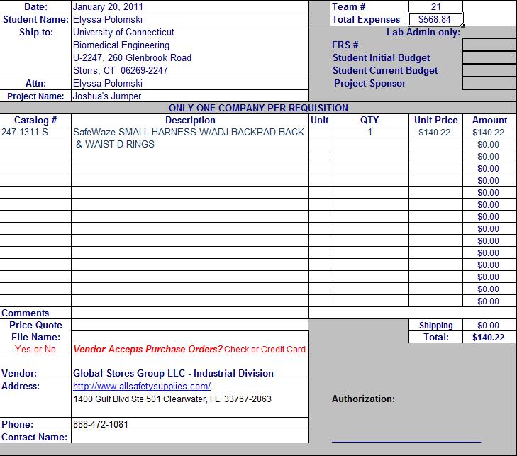
58 57
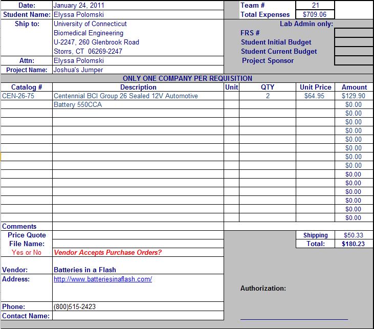
59 58
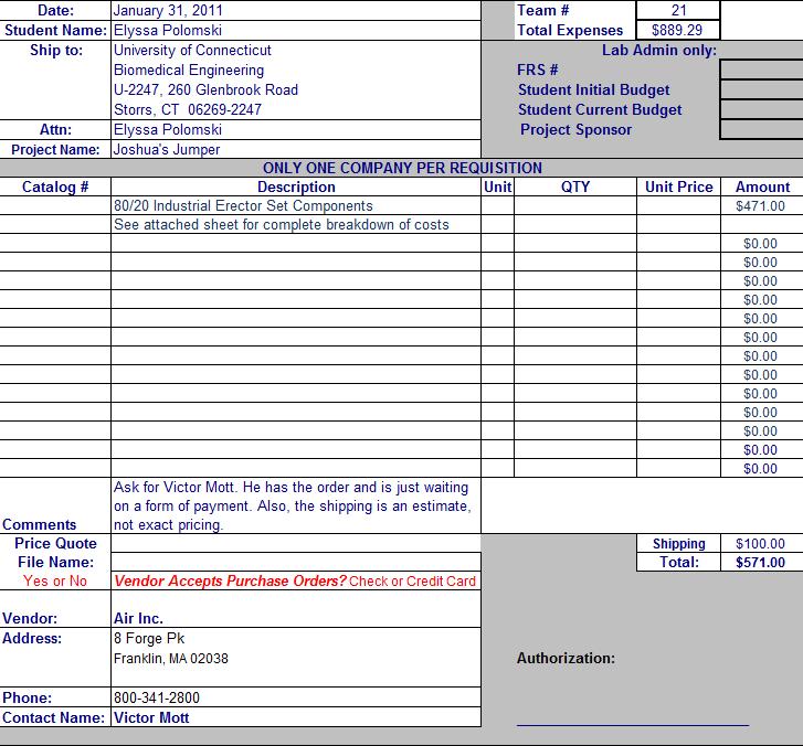
60 59
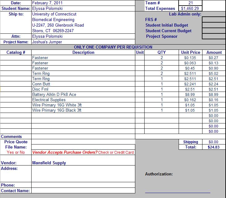
61 60
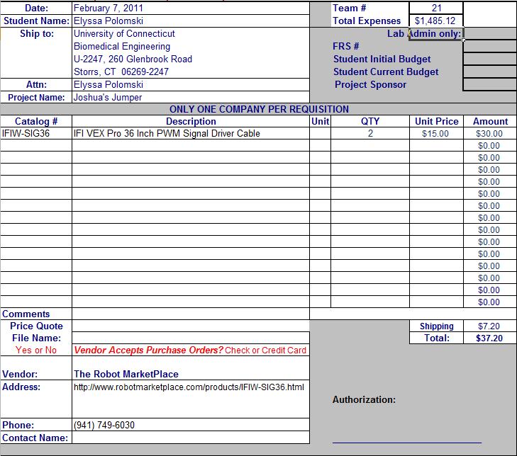
62 61
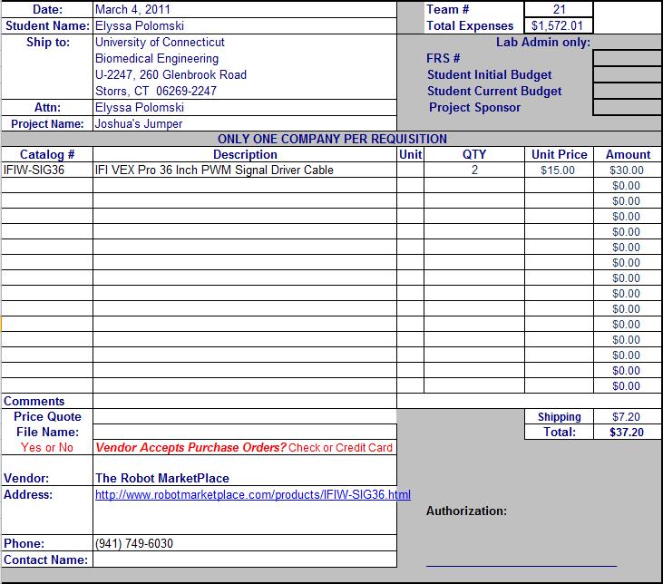
63 62
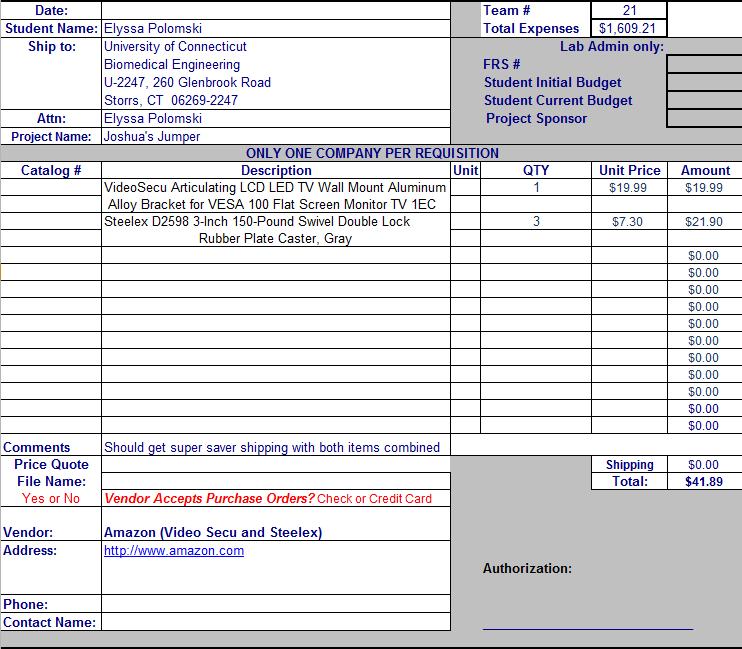
64 63

65 Other (Datasheets, etc.) Transmitter Datasheet

66 Radio Receiver Datasheet 65
67 IFI VEX Pro Vector 884 Speed Controller Users Manual 66
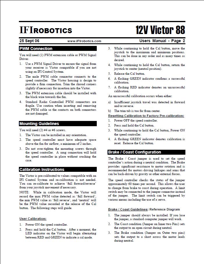
68 67
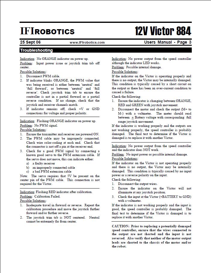
69 68
70 NPC Motor CAD Drawing 69
71 70 Drawing From Ryan Zettle of 80/20. Quote from Ryan Zettle of 80/20.
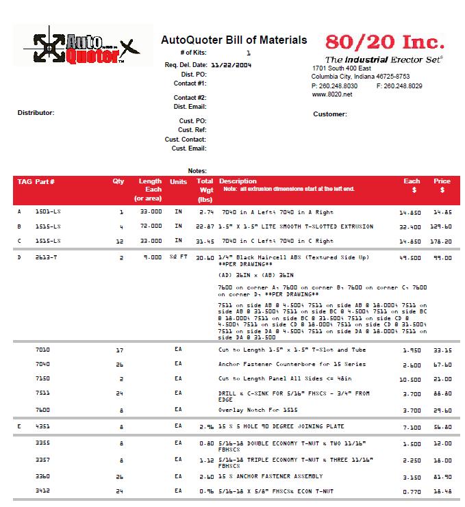
72 71
4. Optimal Design Saddle Eating Chair
 4. Optimal Design Saddle Eating Chair Introduction This chair is designed to give Elysa freedom of motion with her legs while sitting in the chair and also this chair will allow her arms free motion. This
Portable Beach Wheelchair Optimal Design Report
 Portable Beach Wheelchair Optimal Design Report Beach Wheelchair for Jack Davies By Maya Alfonso Matthew Ellis Danielle LaPointe Kyle O Brien Team 13 Project for Matthew and Jack Davies Client Contact:
Project Proposal. Go-Kart for Shane Davis. Team #3: Steven Kapinos Brian Lewis Anthony Vessicchio
 Project Proposal Go-Kart for Shane Davis Team #3: Steven Kapinos Brian Lewis Anthony Vessicchio Client Contact: Shane Davis 6 Sunrise Drive Columbia, CT (954)-850-5448 quarrion1227@gmail.com 2 Executive
Operator s Manual. Single Hand Manual Drive Wheelchair
 Operator s Manual Single Hand Manual Drive Wheelchair Jordan R. Smith Kayla Gosse Leah McElhaney Team #5 Project for Client: Danielle Giroux Client Contact Information: Dave and Suzanne Giroux 53 Charlotte
Automated Retracting Coaster Slide (ARC Slide)
") Automated Retracting Coaster Slide (ARC Slide) Team #7: Sarmad Ahmad Hillary Doucette Stephen Kustra National Science Foundation Katrina Toce djtkmt@cox.net (860) 621-8616 Executive Summary The overall
Automated Retracting Coaster Slide (ARC Slide) Team #7: Sarmad Ahmad Hillary Doucette Stephen Kustra National Science Foundation Katrina Toce djtkmt@cox.net (860) 621-8616 Executive Summary The overall
Complement your Zippie with the JAY Zip Cushion and Back designed just for kids! Pediatric Wheelchair Portfolio
 4 Complement your Zippie with the JAY Zip Cushion and Back designed just for kids! Pediatric Wheelchair Portfolio JAY Zip Back Versatile One Step Release Hardware Easy one step release Fits on wide range
The HTS HTS ( HYGIENE & TOILETING SYSTEM)
") The HTS Hygienic, simple, affordable and adaptable to most toilets, the Hygiene and Toileting System (HTS) is designed to improve the health of your client and the life of the caregiver. For tight budgets
The HTS Hygienic, simple, affordable and adaptable to most toilets, the Hygiene and Toileting System (HTS) is designed to improve the health of your client and the life of the caregiver. For tight budgets
VERSATILE durable. soft to the touch. 3-year Manufacturer s Warranty
 VERSATILE durable adjustable SUPPORT soft to the touch 3-year Manufacturer s Warranty Regular Head Lateral Head Proper Made Easy Multi-Positioning Seat To securely hold your child in place with the proper
Large Activity Chair (R870)
") Large Activity Chair (R870) Activity Chair We knew we had a good chair when we first introduced the medium Activity Chair. After all, our product designers had collected input from hundreds of therapists.
Large Activity Chair (R870) Activity Chair We knew we had a good chair when we first introduced the medium Activity Chair. After all, our product designers had collected input from hundreds of therapists.
SAE Mini BAJA: Suspension and Steering
 SAE Mini BAJA: Suspension and Steering By Zane Cross, Kyle Egan, Nick Garry, Trevor Hochhaus Team 11 Progress Report Submitted towards partial fulfillment of the requirements for Mechanical Engineering
Convaid R82 fixed tilt wheelchairs are lightweight, compact folding, convenient and designed with the child in mind.
 Product Guide 2018 Fixed Tilt Convaid R82 fixed tilt wheelchairs are lightweight, compact folding, convenient and designed with the child in mind. Convaid EZ Rider Lightweight, portable and folds compactly
Folding Shopping Cart Design Report
 Folding Shopping Cart Design Report EDSGN 100 Section 010, Team #4 Submission Date- 10/28/2013 Group Image with Prototype Submitted by: Arafat Hossain, Mack Burgess, Jake Covell, and Connor Pechko (in
Which Mobility Product
 Which Mobility Product is Right for Me? Thousands of Americans affected by disease or disability have found a way back to mobility and the activities they used to enjoy with a scooter or power wheelchair.
Advancement Chair. R901, R902, & R903 Product Manual
 Advancement Chair R901, R902, & R903 Product Manual Contents Warnings and Important Information 3 Recommended Use 4 User and Item Dimensions 4 Assembly and Adjustment Information 5 Maintenance 14 Cleaning
HAUSMANN MOST POPULAR
 HAUSMANN MOST POPULAR TREATMENT TABLES A. Model 4002 A. Series 4002 H-brace is recessed into table leg with unique 4-sided Lock-Tite joint. High pressure laminate legs, apron and stretchers. B. Model 4024
Vehicle Seating REHAB EQUIPMENT, TAILORED FOR YOUR LIFE.
 Vehicle Seating REHAB EQUIPMENT, TAILORED FOR YOUR LIFE. Contents Vehicle Seating Carrot 3000 Carrot XL Timy Car Seat Houdini Harness page page page page 2-3 4-5 6-7 8-9 1 Carrot 3000 2 Designed, engineered
Project Statement. Go Kart for Nathan Lamb
 Project Statement Go Kart for Nathan Lamb TEAM 9 Cameron Fulton Solomiya Teterichko Robert Amatuli Client Contact: Janice M. Lamb 142 Barnes Road Stonington, CT Phone: (860)-460-1394 Fax: (860)-245-5699
190/195 Tilt Shower Commode User Manual
 ... 190/195 Tilt Shower Commode User Manual Healthline Products 1065 E Story Rd Winter Garden Florida 34787 Fax 407-656-5641 Toll Free: 800-987-3577 Product Information This series of rehab commodes offer
Uplift Power Seat Users Guide
 Safety Precautions 1. Use the Uplift Power Seat only in armchairs or sofas with at least one armrest for optimum stability when sitting or rising. 2. Uplift Power Seat is not intended for use in rocking
Large Tricycle (Wrangler) R140 Product Manual
 R140 Product Manual") Large Tricycle (Wrangler) R140 Product Manual Contents Warnings and Important Information 3 Recommended Use 4 User and Item Dimensions 4 Checking Your Order 4 The Frame 5 The Handlebar and Handbrake 6
Large Tricycle (Wrangler) R140 Product Manual Contents Warnings and Important Information 3 Recommended Use 4 User and Item Dimensions 4 Checking Your Order 4 The Frame 5 The Handlebar and Handbrake 6
Alternative Design 1
 Alternative Design 1 Beach Wheelchair Team 13: Maya Alfonso, Matthew Ellis, Danielle LaPointe, Kyle O Brien Project for Matthew and Jack Davies Client Contact: Thomas and Kathleen Davies, 14 Chesterwood
T E A M 5 K A Y L A G O S S E, L E A H M C E L H A N E Y, J O R D A N S M I T H A P R I L 2 0, B M E
 Final Presentation Accessible Laptop Tray for Julia Hall One-Armed Drive Manual Wheelchair for Danielle Giroux Automatic Lift System for Danielle Giroux T E A M 5 K A Y L A G O S S E, L E A H M C E L H
Collapsible, Lightweight Power Chair. By Kristie Astoria, Farrukh Rahman & Nathan Storie
 Collapsible, Lightweight Power Chair By Kristie Astoria, Farrukh Rahman & Nathan Storie Client Contact: Susan Lucek dlucek@nerac.com Tolland, CT Phone Number: 860-872-7000 ext 1008 Executive Summary Annalee
Go Kart For Nathan Lamb
 Go Kart For Nathan Lamb Client Contact: Janice M. Lamb 142 Barnes Road Stonington, CT (860)-460-1394, Janice.lamb@linde.com Team 9: Robert Amatuli, Jr. Cameron Fulton Solomiya Teterichko Overview The Client
Supplying Hospitals for Over 90 Years. User Guide MDS86825SLR. Ultra-Light Rollator
 Supplying Hospitals for Over 90 Years User Guide MDS86825SLR Ultra-Light Rollator Revised: July 1, 2008 Contents Ultra-Light Rollator Features... 3 Rollator Components... 4 Safety Instructions... 5 Assembly
Operator's Manual. Partial Weight Bearing System for Gait Training Therapy. By Craig Hanna, Kyle Hamilton, and Nicholas Woolsey
 Operator's Manual Partial Weight Bearing System for Gait Training Therapy By Craig Hanna, Kyle Hamilton, and Nicholas Woolsey University of Connecticut Biomedical Engineering Senior Design Team #11 Client
LinidoSolutions wall mounted bathroom safety aids and accessories May
 LinidoSolutions wall mounted bathroom safety aids and accessories May 2015 www.handicare.com 1 Personal matters Going to the toilet, but also showering and bathing, are very personal matters which people
The DR-Z70 is designed for use by children and off road use only do not use on public roads. Single rider only weight limit 40 kg (88 lbs.).
.") 2016 Suzuki DR-Z70 The time has come to get your little ones on the dirt! The Suzuki DR-Z70 brings ease and convenience to young riders getting started on two wheels. With an automatic clutch, 3-speed
2016 Suzuki DR-Z70 The time has come to get your little ones on the dirt! The Suzuki DR-Z70 brings ease and convenience to young riders getting started on two wheels. With an automatic clutch, 3-speed
Final Report. Beach Wheelchair. Maya Alfonso, Matthew Ellis, Danielle LaPointe, Kyle O Brien. Team 13
 1 Final Report Beach Wheelchair Maya Alfonso, Matthew Ellis, Danielle LaPointe, Kyle O Brien Team 13 Client Contact: Thomas and Kathleen Davies, 14 Chesterwood Court, Cheshire, CT 06410, (203) 250-7508
Owner s Instructions and Safety Manual. Double-Double series. Performance Bicycle Trailers
 Owner s Instructions and Safety Manual Double-Double series TM Performance Bicycle Trailers Contents 1. Trailer Components 2. Tow Bar and Hitch Components 3. Assembling Your Trailer 4. Attaching the Wheels
Low Center of Gravity All-Terrain Power Chair
 Low Center of Gravity All-Terrain Power Chair by Vikram Shenoy, Niaz Khan, Selome Mandefro, Alex Mann Annalee Hughes, NSF Projects Tolland, CT; (860)-872-7000 Executive Summary This project involves the
Operators Manual. Customized Tilt-in-Space Wheelchair for Abby Miller. By: Katie Guineau, Julia Olczyk, Ben Marcus Team 11
 Operators Manual Customized Tilt-in-Space Wheelchair for Abby Miller By: Katie Guineau, Julia Olczyk, Ben Marcus Team 11 Abby Miller and the Miller Family Clinton, Illinois julie_miller.1367@yahoo.com
Zippie Family. Album
 Zippie Family Album Why Zippie? Bright, busy kids are exciting. Everything they do revolves around their independence and their ability to fit in and be part of the gang. When you think of Zippie think
Action 1NG. Invacare. Simple, robust and efficient!
 Action 1NG Simple, robust and efficient! The Invacare Action 1NG, although made of steel, remains a lightweight wheelchair of exceptional quality. The rigidizer blocks, commonly used with the Action Family
Setup Guide and Chassis Tuning Tips (simple version) By Jim Daniels
 By Jim Daniels") This document is released into the public domain and may be reproduced and distributed in its entirety so long as all credit to Jim Daniels remains. If you find this guide helpful please consider donating
This document is released into the public domain and may be reproduced and distributed in its entirety so long as all credit to Jim Daniels remains. If you find this guide helpful please consider donating
Electrical Engineering Within a Robotic System
 Electrical Engineering Within a Robotic System Carli Hand Fall, 2016 Synopsis The NASA Robotics Mining Competition (RMC) is held every year at Kennedy Space Center, Florida. Fifty universities assemble
Lifting Mechanisms. Example 1: Two Stage Lift
 Lifting Mechanisms The primary scoring method for the 2018 game is to deposit fuel cubes into scoring zones. A manipulator fixed to your robot can deliver fuel cubes into ground level scoring zones, but
THE STATE OF THE ART IN MOBILITY
 THE STATE OF THE ART IN MOBILITY YOUR BRIDGE TO A MORE INDEPENDENT LIFE WHY NUPRODX MISSION Nuprodx Mobility improves safety in and around the bathroom for seniors and people with disabilities, fostering
PRODUCT CATALOG.
 PRODUCT CATALOG www.ablelifesolutions.com i TABLE OF CONTENTS BEDSIDE EXTEND-A-RAIL SECURE TO ANY BED WITH INCLUDED SAFETY STRAP Pages 1-2 RECLINER HANDLE EXTENDER ADJUST YOUR CHAIR WITH EASE Pages 15-16
Accessible Housing by Design Residential Hoists and Ceiling Lifts
 about your house CE 63d Accessible Housing by Design Residential Hoists and Ceiling Lifts universal design People who inhabit and visit our dwellings come in all shapes and sizes, range in age from infant
EZ LITE CRUISER. Service & Maintenance Manual
 EZ LITE CRUISER Service & Maintenance Manual Table Of Contents Introduction to the EZ Lite Cruiser 3 Identification of Components 4 Controller System Component Diagram 6 Controller System I/O Ports Detail
Alternative Design Report Work Station and Pool Lift
 Alternative Design Report Work Station and Pool Lift TEAM #1 Ana Groff Brandon Calavan Dylan Rinker Sebastian Pineo Steven Ben Faculty Advisor: John Enderle Teaching Assistant: Sarah Brittain Project 2
expandable booster Instruction Manual US Version
 expandable booster Instruction Manual US Version product: monterey expandable booster model series: 15000 mfg. by: Diono LLC 14810 Puyallup Avenue Sumner, WA 98390 Customer Care Tel: 1 (855) 463-4666 us.diono.com
An innovative child safety seat designed for children with special health needs. Listening to therapists working with families
 An innovative child safety seat designed for children with special health needs Listening to therapists working with families Features EZ-Up Cap Three sizes available EZ-Up Head Rest Cover Incontinent
Installation Manual. For. High Speed Alumavator and Platinum. 10 and 23 Degree. Elevator Boat Lifts
 Installation Manual For High Speed Alumavator and Platinum 10 and 23 Degree Elevator Boat Lifts Page 2 Safety Precautions 1. Your boat lift is a heavy duty piece of equipment. It is important that all
PowerTech Vent Power Center The World s First Power Supply Specifically Designed to Power a Ventilator From your Wheelchairs Batteries!
 INCORPORATED PowerTech Vent Power Center The World s First Power Supply Specifically Designed to Power a Ventilator From your Wheelchairs Batteries! Patented Technology United States Patent No. US 6,222,282
Tandem User Instructions
 Tandem User Instructions Issued 1 st November 2014 Tandem Buggy We designed the tandem buggy to enable families who have a disabled child and another younger child to enjoy the freedom they deserve. The
CONVERTIBLE CAR SEAT ISOFIX COMPATIBLE Birth to 4 years (approx)
") CONVERTIBLE CAR SEAT ISOFIX COMPATIBLE Birth to 4 years (approx) REARWARD FACING Birth to 2-3 years (approx) Series No. BS7200A-i20133 FORWARD FACING 12 months to 4 years (approx) IMPORTANT: KEEP THIS
CONVERTIBLE CAR SEAT ISOFIX COMPATIBLE Birth to 4 years (approx) REARWARD FACING Birth to 2-3 years (approx) Series No. BS7200A-i20133 FORWARD FACING 12 months to 4 years (approx) IMPORTANT: KEEP THIS
Pro Battery-Powered Floor Lift
 Pro Battery-Powered Floor Lift provide safer and more secure transfers of patients by caregivers. Lumex lifts are very sturdy and easy to use. Optional digital scale DSC270 and rubber-coated low base legs
Table of Contents. Executive Summary...4. Introduction Integrated System...6. Mobile Platform...7. Actuation...8. Sensors...9. Behaviors...
 TaleGator Nyal Jennings 4/22/13 University of Florida Email: Magicman01@ufl.edu TAs: Ryan Chilton Josh Weaver Instructors: Dr. A. Antonio Arroyo Dr. Eric M. Schwartz Table of Contents Abstract...3 Executive
Booster Car Seat User Guide
 Booster Car Seat User Guide For future use, STORE USER GUIDE in location on bottom of base. IS0133.E 2015 Artsana USA, Inc. If you have any problems with your Chicco Booster Seat, or any questions regarding
M:2:I Milestone 2 Final Installation and Ground Test
 Iowa State University AerE 294X/AerE 494X Make to Innovate M:2:I Milestone 2 Final Installation and Ground Test Author(s): Angie Burke Christopher McGrory Mitchell Skatter Kathryn Spierings Ryan Story
DESIGN AND DEVELOPMENT OF A SUSPENSION SYSTEM USED IN ROUGH- TERRAIN VEHICLE CONTROL FOR VIBRATION SUPPRESSION IN PLANETARY EXPLORATION
 DESIGN AND DEVELOPMENT OF A SUSPENSION SYSTEM USED IN ROUGH- TERRAIN VEHICLE CONTROL FOR VIBRATION SUPPRESSION IN PLANETARY EXPLORATION Arvin Niro College of Engineering University of Hawaiʽi at Mānoa
Installation Manual. For. Alumavator and Platinum. Vertical Installation. Elevator Boat Lifts
 Installation Manual For Alumavator and Platinum Vertical Installation Elevator Boat Lifts Page 2 Safety Precautions 1. Your boat lift is a heavy duty piece of equipment. It is important that all persons
K710 Product Manual. Support Station. K710 Product Manual
 K710 Product Manual Support Station K710 Product Manual Contents Important information 2 Safety messages 3 Recommended use 4 Item dimensions 5 Check your order 6 Installation 6 Basic components 7 Accessories
The Ladder Climber. Design Team. Design Advisor
 The Ladder Climber Design Team Younes Albahrani, Saad Farhad Andres Janna, Jhony Quintal, Shahan Sarkissian Design Advisor Prof. Hamid Hashemi Abstract The goal of this project was to create a low cost
How to Build with the Mindstorm Kit
 How to Build with the Mindstorm Kit There are many resources available Constructopedias Example Robots YouTube Etc. The best way to learn, is to do Remember rule #1: don't be afraid to fail New Rule: don't
Introduction: Problem statement
 Introduction: Problem statement The goal of this project is to develop a catapult system that can be used to throw a squash ball the farthest distance and to be able to have some degree of accuracy with
Instruction Manual US Version
 Rear-facing: 5-45 pounds (2.3-20.5 kg) Forward-facing: 20-65 pounds (9-29.5 kg) Booster mode: 50-120 pounds (23-54 kg) all-in-one convertible Instruction Manual US Version Please read carefully Store manual
expandable booster Instruction Manual US Version
 expandable booster Instruction Manual US Version product: monterey XT expandable booster model series: 108000 mfg. by: Diono US 14810 Puyallup Street E Suite 200 Sumner, WA 98390 Customer Care Tel: 1 855
Foldable Shopping Cart EDSGN 100 Section 202 Team 3
 Foldable Shopping Cart EDSGN 100 Section 202 Team 3 http://personal.psu.edu/jnb5392/homepage.htm Submitted by: Alex Thomason Christian Sak Jeremy Deppen Jerod Barone Submitted to: Xinli Wu 30 July 2015
Many farm injuries can be
 Bulletin 2326 Maine Farm Safety Program by Dawna L. Cyr, farm safety project assistant, and Steven B. Johnson, Ph.D., Extension crops specialist Ladders, Lifting and Falls Many farm injuries can be attributed
Applications in Design & Engine. Analyzing Compound, Robotic Machines
 v2.1 Compound Machines ering Applications in Design & Engine Analyzing Compound, Robotic Machines Educational Objectives At the conclusion of this lesson, students should be able to: Understand the relationship
Sport. Gymnastics. A range of specialised equipment to make life easier for gymnastics coaches. Folding Wedges. Flick Trainers.
 A range of specialised equipment to make life easier for gymnastics coaches. Folding Wedges Folding Wedge Very popular developmental device available in 5 colour coded sizes for easy identification. Ideal
CHAPTER 17 UNIVERSITY OF CONNECTICUT
 CHAPTER 17 UNIVERSITY OF CONNECTICUT School of Engineering Biomedical Engineering 260 Glenbrook Road Storrs, Connecticut 06269 Principal Investigator: John Enderle (860) 486-5521 jenderle@bme.uconn.edu
THE TORQUE GENERATOR OF WILLIAM F. SKINNER
 THE TORQUE GENERATOR OF WILLIAM F. SKINNER IN 1939, WHICH WAS THE START OF WORLD WAR TWO, WILLIAM SKINNER OF MIAMI IN FLORIDA DEMONSTRATED HIS FIFTH-GENERATION SYSTEM WHICH WAS POWERED BY SPINNING WEIGHTS.
Linear Actuators for On/Off-Highway Vehicles
 Linear Actuators for On/Off-Highway Vehicles Thomson Actuators Set the Standard in On-Off Highway Vehicles We are the original actuator manufacturer. For over 40 years, our engineers have worked to design
Instruction Manual. Canada English Version
 Instruction Manual Canada English Version Product: Monterey child booster seat Model: 15000 Mfg. by: Diono Canada, ULC 50 Northland Road, Suite 400 Waterloo, Ontario N2V 1N3 Customer Service Tel: 519-725-1700
Wench With a Wrench. By Gail Wagner. A Shocking Discussion. Should I or Shouldn t I? That is The Question
 By Gail Wagner Wench With a Wrench A Shocking Discussion There are lots of things you want out of your Miata driving experience and one of them is a smooth ride. A key factor that contributes to this experience
Beach Wheelchair and Accessories
 Beach Wheelchair and Accessories Corporate Offices: 203 Arlington Ave Lakewood, NJ 08701 Mailing address: 1995 Rutgers University Blvd. Lakewood, NJ 08701 Tel: 732-348-0312 Fax: 732-348-0412 Email: state@govsupplies.com
RAMPAGE POWER LIFT RAMP
 RAMPAGE POWER LIFT RAMP INSTALLATION AND OPERATING INSTRUCTIONS (3/10/07) The Rampage Power Lift Ramp is the fast, easy, and safe way to load a motorcycle into a truck. One person can load or unload a
Team Drum Roll Mobile Marching Band Drum Set
 Team Drum Roll Mobile Marching Band Drum Set University of Idaho Mechanical Engineering Senior Design Summer Fall 2011 Aaron Braithwaite Justin Dilworth Sarah Helland Toni Töpfer brai2587@vandals.uidaho.edu
smart features Comfort, Safety and Value
 smart features for mature drivers Comfort, Safety and Value Vehicle Features that Meet Your Needs In cooperation with the National Older Driver Research & Training Center at the University of Florida Mature
AUTOMATIC CLOSING WINDOW
 MECHANICAL ENGINEERING DEPARTMENT AUTOMATIC CLOSING WINDOW ASSESSMENT III- GRADUATION PROJECT Advisor: Dr. Emad Y. Tanbour Mohd. Abdul Mohsin Khan Mohd. Al- Ghamdi Nemer Saab Contents Introduction Problem
Table of Contents. Tilt Wheelchair. Folding Wheelchair. power Wheelchair. commodes. At Power Plus Mobility, We care!
 Table of Contents 01 05 09 Tilt Wheelchair STP EXTREME NV TILT 13 17 21 Folding Wheelchair MAGIC PLUS VOYAGER PLUS GLYDER 25 power Wheelchair MP5 29 31 commodes HORIZON HORIZON TILT At Power Plus Mobility,
Phoenix Buggy User Instructions
 Phoenix Buggy User Instructions Issued 1 st March 2015 Introduction Welcome to the Phoenix Buggy User Guide. The Phoenix Buggy has been designed to provide a robust, transportable mobility solution for
TDX 2 Ultra featuring
 Ultimate Control. Ultimate Comfort. The Invacare TDX2 Ultra is an elite, high performance, centre wheel drive power wheelchair equipped with the advanced Ultra Low Maxx seating system. Designed to be the
Cornell University Autonomous Underwater Vehicle Team Spring Frame
 Cornell University Autonomous Underwater Vehicle Team Spring 2014 Frame Technical Report Kent Esslinger (kde26) May 21, 2014 Contents 1 Abstract 2 2 Design Requirements 2 3 Previous Designs 3 3.1 Drekar...............................
SAE Mini BAJA: Suspension and Steering
 SAE Mini BAJA: Suspension and Steering By Zane Cross, Kyle Egan, Nick Garry, Trevor Hochhaus Team 11 Project Progress Submitted towards partial fulfillment of the requirements for Mechanical Engineering
Load cells for a Portable Structure
 Load cells for a Portable Structure Load Restoring force Side force We know that a weighing system must be rigid to get good results. We should also know that a three point system is inherently more stable
Remote Control Helicopter. Engineering Analysis Document
 Remote Control Helicopter By Abdul Aldulaimi, Travis Cole, David Cosio, Matt Finch, Jacob Ruechel, Randy Van Dusen Team 04 Engineering Analysis Document Submitted towards partial fulfillment of the requirements
Engineering Design Process for BEST Robotics JANNE ACKERMAN COLLIN COUNTY (COCO) BEST & BEST OF TEXAS ROBOTICS
 BEST & BEST OF TEXAS ROBOTICS") Engineering Design Process for BEST Robotics JANNE ACKERMAN COLLIN COUNTY (COCO) BEST & BEST OF TEXAS ROBOTICS Agenda Getting Started Lessons Learned Design Process Engineering Mechanics 2 Save Time Complete
Engineering Design Process for BEST Robotics JANNE ACKERMAN COLLIN COUNTY (COCO) BEST & BEST OF TEXAS ROBOTICS Agenda Getting Started Lessons Learned Design Process Engineering Mechanics 2 Save Time Complete
Platforms, hoists and outriggers
 Platforms, hoists and outriggers XSPhilosophy: driven by innovation We are guided by five core values: Safety above all Focus on the customer Simplicity defines quality At XSPlatforms we think that everyone
Chapter 13 UNIVERSITY OF DELAWARE
 Chapter 13 UNIVERSITY OF DELAWARE College of Engineering Department of Mechanical Engineering Newark, Delaware 19716 Principal Investigator: Dick Wilkins (302) 831-2006 wilkins@me.udel.edu 195 196 NSF
ICON BACK SYSTEM featuring VariLock hardware
 LAYHUGLAUGHTRAVELDANCELOVES ORKSIT LIVERELAXEXPERIENCEROLLSHOP ICON BACK SYSTEM featuring VariLock hardware Icon Back System Innovation, Versatility & Comfort For many wheelchair users, a solid back system
Optimal Design Report: Stair Lift System and Walker
 Optimal Design Report: Stair Lift System and Walker By Joseph Wolanski, Nihit Mody, Samir Dahmani Team 2 Client: Heidi Almeida, 32 Parkwood Rd. Waterbury, CT. (203) 910-6543 Advisors: Dr. John Enderle
Autonomously Controlled Front Loader Senior Project Proposal
 Autonomously Controlled Front Loader Senior Project Proposal by Steven Koopman and Jerred Peterson Submitted to: Dr. Schertz, Dr. Anakwa EE 451 Senior Capstone Project December 13, 2007 Project Summary:
20 DRAWER 23 DRAWER. 5, MTZBK7217MZ + MTZBK7200H + MTZBK7203SL Overall Dimensions: 91 W x 30 D x 75-1/2 H. Hutch MTZBK7200H.
 ALL MONTEZUMA TOOL BOXES REQUIRE LIFT GATE SERVICE SKU 301610 MTZLIFTGATE 100 00 TOOL BOX COMBOS 17 DRAWER 20 DRAWER 23 DRAWER 17 Drawer Box with SKU 295815 MTZCOMBO1 4,49 + Overall Dimensions: 72 W x
The Smart Kart. Client Contact: Janice M. Lamb 142 Barnes Road Stonington, CT (860) ,
 ,") Client Contact: Janice M. Lamb 142 Barnes Road Stonington, CT (860)-460-1394, Janice.lamb@linde.com Team 9: Robert Amatuli, Jr. Cameron Fulton Solomiya Teterichko The Smart Kart Overview The Client Limitations
Client Contact: Janice M. Lamb 142 Barnes Road Stonington, CT (860)-460-1394, Janice.lamb@linde.com Team 9: Robert Amatuli, Jr. Cameron Fulton Solomiya Teterichko The Smart Kart Overview The Client Limitations
(12) Patent Application Publication (10) Pub. No.: US 2005/ A1
 Patent Application Publication (10) Pub. No.: US 2005/ A1") US 2005O25344-4A1 (19) United States (12) Patent Application Publication (10) Pub. No.: US 2005/0253444 A1 Godshaw et al. (43) Pub. Date: Nov. 17, 2005 (54) AUTOMOBILE PET BED CONSTRUCTION (22) Filed:
US 2005O25344-4A1 (19) United States (12) Patent Application Publication (10) Pub. No.: US 2005/0253444 A1 Godshaw et al. (43) Pub. Date: Nov. 17, 2005 (54) AUTOMOBILE PET BED CONSTRUCTION (22) Filed:
Futura 20/60. Car Seat OWNER S MANUAL. Models 79013, 79014
 Futura 20/60 Car Seat OWNER S MANUAL Models 79013, 79014 Message to Parents Thank you for choosing the Fisher-Price Futura 20/60 Car Seat. Before you use this car seat, please take time to read and understand
Will the MIM Safe Variocage fit in my vehicle?
 Frequently Asked Questions What makes the MIM Safe Variocage the safest animal transport cage on the market? Will the MIM Safe Variocage fit in my vehicle? How can I choose a Variocage that is the correct
Azalea. Family. One big family. Invacare
 Family One big family Invacare Rea Passive chairs offer users the perfect fit and comfort, with a wide selection of models, options and compatibility across the Family. In order for customers to need only
MEYLAND-SMITH A/S EST User manual for MEYWALK 2000 model Medium and Large
 MEYLAND-SMITH A/S EST. 1901 User manual for MEYWALK 2000 model Medium and Large Introduction These instructions for use contain information on the assembly and adjustment of MEYWALK 2000, how to maintain
Staging and Seating U.S.A Fax Archbold, OH MADE IN THE
 Staging and Seating 1.800.537.0540 Fax 419.445.0367 www.biljax.com Archbold, OH MADE IN THE U.S.A Introducing Multi-Stage Designed to provide a stage unit that is extremely versatile and easy to assemble.
COMMUTER SCOOTER. Design Team Andrew Bates, Christopher Holtzman Michael Lewon, Sant Vangavolu. Design Advisor Professor Jim Papadopoulos
 COMMUTER SCOOTER Design Team Andrew Bates, Christopher Holtzman Michael Lewon, Sant Vangavolu Design Advisor Professor Jim Papadopoulos Abstract In a city environment, most commuters take mass transit.
PLUS. 5 x 9. Magnetic Tray SKU x 11. Magnetic Tray SKU Four Powerful Magnets with Protective Rubber
 STORAGE Workbench Professional Workbench SKU 400312 49 21006 Weight Capacity: 1,200 lbs Overall Dimensions: 60 W x 31 D x34 H 13 Gauge Steel Construction Full Bottom Shelf Durable Powder Coated Finish
Charles Flynn s Permanent Magnet Motor.
 Charles Flynn s Permanent Magnet Motor. Patent US 5,455,474 dated 3rd October 1995 and shown in full in the Appendix, gives details of this interesting design. It says: This invention relates to a method
Connor Needham Roger Williams University Bristol, RI, United States. Jeremy Kacher Roger Williams University Bristol, RI, United States
 ASEE 2014 Zone I Conference, April 3-5, 2014, University of Bridgeport, Bridgpeort, CT, USA. Design of a Vertical Axis Wind Turbine for Urban Areas Hidden In Plain Sight Wind Energy Conservation System
ROBOTICS BUILDING BLOCKS
 ROBOTICS BUILDING BLOCKS 2 CURRICULUM MAP Page Title...Section Estimated Time (minutes) Robotics Building Blocks 0 2 Imaginations Coming Alive 5...Robots - Changing the World 5...Amazing Feat 5...Activity