This publication may be reproduced in whole or in part, stored in a retrieval system, or transmitted, in any form or by any means, electronic,
|
|
|
- Donna Davis
- 5 years ago
- Views:
Transcription


1 Air Conditioning 2017
2 This publication may be reproduced in whole or in part, stored in a retrieval system, or transmitted, in any form or by any means, electronic, mechanical, photocopying, recording or otherwise, without the express permission of SALVADOR ESCODA S.A. All MUNDOCLIMA equipment has a 2-year warranty on parts and labor, provided that the fault arises from a manufacturing defect and is not attributable to the installation. To make use of the guarantee, the user must keep the purchase invoice and contact MUNDOCLIMA HELPDESK to follow the instructions that will be detailed for the correct resolution of the incident. The information detailed in this Catalog (product photos, dimensions, performance, features, etc.) are subject to change without prior notice, in order to introduce technical improvements or innovations.
3 INDEX COMPANY PROFILE...2 ENERGY SAVING...3 EMBLEMATIC WORKS... 4 to 5 BENEFIT LEGEND... 6 to 7 MULTIFUNCTION REMOTE CONTROL...8 DOMESTIC RANGE Names...9 Product range to 11 MUPR-H7 Wall split to 15 MUPR-H6 Wall split to 17 MUPR-H5A Wall split to 19 MUEX-H6 Multisplit Outside unit to 22 MUPR-H6M Wall Multisplit...23 MUCSR-H6M Multisplit cassette type...24 MUCR-H6M Multisplit duct type...25 H6 Multisplit Selection...26 MUVR-C6 Window Air Conditioner...27 MUPO C6/H6 Portable Air Conditioner...28 MU-WZ Air Conditioner without Outdoor Unit...29 COMMERCIAL RANGE Names...9 Product range to 11 MUCSR-H6 Split cassette type to 37 MUSTR-H6 Floor-Ceiling Split Type to 42 MUCR-H6 Split Duct Type...43 a 47 MUCHR-H7 High Capacity Duct Split to 49 MUCHR-H6 High Capacity Duct Split to 51 MUCHR-H6A High Capacity Duct Split to 53 MUCO-H6 Floor Standing Split to 55 INDUSTRIAL RANGE (MVD Series) OUTDOOR UNITS Name...58 Product range...59 Mini MVD V to 66 Maxi MVD V5X 2 pipes to 74 Maxi MVD VR4+ 3 pipes to 83 INDOOR UNITS Name...84 Product range...85 Cassette 4 ways DC...86 Cassette 4 ways Compact DC...87 Low Silhouette (extra-flat) duct DC to 89 High pressure duct DC...90 High pressure duct D Duct 100% Outdoor air DC...92 Floor/Ceiling DC...93 Wall split DC...94 Wall split D Floor fan coil unit DC...96 Floor unit with casing DC...97 Floor unit without casing DC...98 Hidrobox MVD VR Distributors Selection program INDUSTRIAL RANGE (Hydronic Series) FAN COILS UNITS Name Product range MUP-W7 Wall-mounted MUCS-W7 Cassette MUCSW-HG Cassette MUC-W7/SE-CE Floor/Ceiling to 110 Floor/Ceiling MUC-CE4/SE to 113 MUC-HP4 High Pressure Duct to 115 WATER CHILLER Name Product range MUENR-H6 Inverter to 119 MUEN-H6 Digital Scroll to 121 CONTROL SYSTEMS Range to 127 Wireless Controls to 129 Wired Controls to 133 Centralized Controls to 135 Integral Control BMS Control to 139 WIFI Controls to 142 Accessories to 147 Functions Summary to 149 AEROTHERM Aerotherm V17 Series: Monobloc and Bibloc to 159 Heat pump for SHW Monobloc System Heat pump for SHW Monobloc System HEAT RECOVERY UNITS MURE Enthalpic Units MU-RECO SN Thermal Units to 167 AIR CURTAINS SILVER INOX MU-ECO MU-ECO GC MU-CA MU-CA GREAT HEIGHT AC MU-EMP DEHUMIDIFIER, HEATERS AND EVAPORATIVE UNITS DEHUMIDIFIER MH-10-V5 / MH-20-V MH-40-V MH-60-N / MH-80-N HEATERS MUR Economic Series MUR-LUXUS Luxus Series EVAPORATIVE AIR CONDITIONERS MUEV-ECO Heating Series MUEV-C7 Only Cooling Series

4 Company Profile MUNDOCLIMA is a registered trademark of Salvador Escoda S.A., leader in the Spanish market for the distribution of products for air conditioning, ventilation, heating, cooling and insulation installations. MUNDOCLIMA encompasses an extensive range of products for air conditioning, whose main objective is to provide the customer with added value, not only limited to air conditioning, but also to generate a state of comfort through the intelligent treatment of air. All MUNDOCLIMA products are developed from the premises of sustainable development and respect for the environment. These lines of development give rise to products of low energy consumption, high efficiency and low sound level that are perfectly adapted to the needs of our customers. All these advantages place MUNDOCLIMA among the brands that best balance the commitment between price and quality. MUNDOCLIMA also counts on an ample human team whose main function is the previous advice to the development of projects, as well as an effective and fast After Sales service that solves any need of our clients. Why MUNDOCLIMA? Because we have the best value for money on the market. We do not have to pay for expensive television commercials, billboards or newspapers advertising, and our customers benefit directly from this. Because we offer the best Post- Sale Technical Support of the national territory with full coverage, without 902 phones numbers type that charge when you have a problem. Because for us the most important thing is the satisfaction of our client and we do everything possible to ensure it. Because we have been air conditioning homes in Spain and the rest of Europe for 40 years and we want to continue to do so in the future. Because we are environmentally friendly and we want to help for the protection of the ozone layer. For that reason we only use environmentally friendly refrigerants and equipment with a high energy efficiency. And above all this...because we are from here. We are a team of more than 500 professionals who understand your needs and are prepared to provide you with the supplies and advice your company needs. 2
 SEER 8.50 SCOP 5.10 6.10 SEER < 8.50 4.60 SCOP < 5.10 5.60 SEER < 6.10 4.00 SCOP < 4.60 5.10 SEER < 5.60 3.40 SCOP < 4.")

5 Energy Saving ENERGY EFFICIENCY SEER SCOP The MUNDOCLIMA equipment complies with the ERP directive on Ecodesign, they have the new energy labeling, which establishes minimum values of energy efficiency for both cooling mode and heating mode. CLASS A++ SEER (MUPR Series) SEER 8.50 SCOP SEER < SCOP < SEER < SCOP < SEER < SCOP < SEER < SCOP < SEER < SCOP < SEER < SCOP < 2.80 ENERGY EFFICIENCY CLASS The label distinguishes between climatic zones, offering the consumer more detailed data, which allows the user to know better the performances according to the climatic zone where he/she is. CLIMATIC ZONES: Three climatic zones are shown, as can be seen on the map. - Intermediate (mandatory) annual temperature of Strasbourg. - Warm annual temperature of Athens. - Cold annual temperature of Helsinki. SEER and SCOP: Performance values indicating Seasonal Efficiency in Cooling (SEER) and Heating (SCOP) calculated by hours of annual use in different climatic zones. ENERGY CLASS: In cooling and heating, the energy labels show a scale reaching values of A +++. SOUND LEVELS: The sound power level of the indoor and outdoor units. Absolute Silence Only 20 db(a) * Silent mode sound pressure MUPR-09-H6 3

 Maxi")


")


 Maxi")
6 EMBLEMATIC WORKS Mas Falet Hotel (San Antoni de Calonge) Maxi MVD 450 kw Cooling power Shopping Center MAREMAGNUM (Barcelona) Maxi MVD 450 kw Cooling power 64 Offices Diagonal (Barcelona) Extra Flat Inverter Duct Units Car Dealership (Sant Boi de Llobregat) Maxi MVD 130 kw with high pressure duct DC 4

 Water")


 Maxi")


7 EMBLEMATIC WORKS Graus 4 Star Hotel (Huesca) Water Chiller and Fan coil uts. 80kW cooling power. Ecoparc del Mediterrani Air handling unit with recovery Monzon Catering Hall (Huesca) Maxi MVD 105 kw Cooling power Cal Repissa Town Hall (Olesa de Montserrat) Maxi MVD 45kW Cooling power 5
8 LEGEND OF PERFORMANCES Comfort WEEKLY TIMER Sets the weekly operation of the unit. FOLLOW ME FUNCTION (IFEEL) The remote control incorporates an ambient temperature sensor. AUTOMATIC RESTART Recovery of the adjustments before the electrical cut. EMERGENCY OPERATION Possibility of unit operation with the manual button in case of activation of some alarms. COLD AIR PROTECTION In heating, the initial fan speed is adjusted in accordance with the coil temperature. TURBO OPERATION Maximum cooling/heating time reduction. LOW SOUND LEVEL Thanks to the Silence mode and its new design, the sound level is reduced to the minimum. TEMPERATURE COMPENSATION The RG57 remote control allows you to set the compensation temperature for heating and cooling mode. QUIETER OUTDOOR UNIT Optimized design of air outlet grille with noise reduction of 3.3dB (A) compared to previous models. WIDE WORKING TEMPERATURE RANGE Cooling operation until 50 C and in heating up to -15 C. NIGHT MODE This function automatically increases or drops indoor temperature by 1 C per hour during the first 2 h, and then keeps constant temp. for the next 5 h before turning off. This function is energysaving and provides night comfort. DAILY TIMER The timer can be set to start and stop at any point in a 24-hour period. DESIGN 360 Thanks to the 360 panel design, the air is more evenly distributed. HORIZONTAL AND VERTICAL BLADE SWING Better air distribution thanks to the automatic blade swing, horizontal and vertical. VENTILATION FUNCTION It allows operation with only ventilation. THERMOSTAT It keeps automatically the set temperature. DEHUMIDIFICATION Moisture reduction restoring an optimum temperature in wet areas. MULTI-SPEED INDOOR FAN Up to 12 levels of fan speed automatically adjusted if the automatic ventilation is activated. Connectivity WIFI Possibility that the unit is controlled via WIFI, through its own module and mobile app. CENTRALIZED CONTROLLER CCM Possibility to control several units from only one remote control. The remote control can directly control up to 64 units of different systems. Energy efficiency ENERGY LABELLING FOR COOLING A++ ENERGY LABELLING FOR COOLING A ENERGY LABELLING FOR COOLING A+ ENERGY LABELLING FOR COOLING A STANDBY FUNCTION (ONLY 1W IN STANDBY) The outdoor unit is automatically disconnected from the supply when the unit is in standby, in that way the consumption in standby modus is only 1W. Refrigerant R410A Unit that uses R410A refrigerant. R32 Unit that uses more environmentally friendly refrigerant: R32. 6
9 LEGEND OF PERFORMANCES Easy installation and maintenance OUTSIDE AIR INLET Possibility of supplying outdoor air directly on the indoor unit. DRAINAGE PUMP It incorporates drainage pump to facilitate the drainage of the indoor unit. REMINDER CLEANING FILTER The equipment tells us when to clean and / or replace the air filter of the indoor unit. PIPE COMPATIBILITY Possibility of increasing a size over the standard diameter in the gas pipe. DIGITAL DISPLAY LED Equipment with a digital display showing the setpoint temperature during normal operation or the ambient temperature in ventilation mode. LESS SCREWS Not only the indoor unit but also the outdoor unit have less screws, so the disassembly is going to be easier. REFRIGERANT LEAK DETECTION The unit automatically detects the existence of possible leaks of refrigerant in the circuit. SET TEMPERATURES RANGE ADJUSTMENT The new remote control is able to adjust: Minimum cooling from 17 C up to 24 C; Maximum heating from 30 C up to 25 C. FEET IN U FORM Thanks to the new back feet in the outdoor unit, installation is easier. LOW VOLTAGE START The equipment can start and run normally up to a supply voltage of 165 V. PROBLEM SOLVING Error codes are showed in the indoor panel, wall control and outdoor PCB. REMOTE SIGNS (CP) The indoor unit has an ON/OFF input. CONFIGURABLE STATIC PRESSURE The static pressure of the fan can be adjusted using the PCB or the wireless control RG57. In this way, the machine can be adapted to each installation. CONFIGURABLE RETURN The air intake can be set up either at the rear or at the bottom of the unit. By default, it is set up at the rear. TWIN FUNCTION (2 X 1) Two indoor units can be connected to the same outdoor unit. Both indoor units will function identically as if they were one single unit. It is perfect for open rooms. AUTO ADDRESSING The outdoor unit can assign address to the indoor units automatically. ADJUSTMENT Function adjustment and query of operating parameters using the RG57 wireless control. EXTRA FLAT DUCT Height of the indoor unit of only 210 mm. DELIVERY OUTLET TO ADJACENT ROOM The unit has pre-cut outlets for connecting a small duct and airconditioning the next room. AIR DISCHARGE TUBE TO THE OUTSIDE Easy and quick to install, it allows the use of the air conditioner immediately. CONDENSATE REMOVAL Removes condensate water so it is not necessary to connect the air conditioner to a drain. In dehumidification mode and in very humid environments, it is recommended to connect the equipment to a drain. PANEL OF COMPACT SIZE The trim panel of the cassette type unit measures mm. Technology SUPER DC Equipment that has both, DC Inverter compressor and DC fan motors. COOLING UNDER LOW TEMPERATURES Operation in cooling up to -15 C outdoor temperature. DC Unit with DC fan motor, low noise and low-energy consumption. OPERATION TO 50/60 HZ Possibility to connect the equipment to 50 or 60 Hz. SCROLL Asymmetric scroll compressor of high efficiency. DIFFERENT SPEEDS OF THE EXTERNAL FUN Accurate adjustment of fan speed thanks to DC fan. 7

10 MULTIFUNCTION REMOTE CONTROL RG57 Model MULTIPLE CONFIGURATIONS The remote control RG57 allows to adjust different functions of the equipment. Set the parameters as desired: Function Auto-restart function Operation Compensation Fan speed setting SET TEMPERATURES RANGE ADJUSTMENT Adjustment Active/Inactive Adjust the value from 0 C to 6 C Adjust fan speed as desired Minimum cooling from 17 C up to 24 C Maximum heating from 30 C up to 25 C SAVE TIME IN MAINTENANCE The new remote control also allows you to check operating parameters. Check the operating frequency or temperature of all sensors of the equipment easily. RG57A6/BGE Note: Only for domestic range H6, H6M and H7, and commercial H6 (except high capacity duct and column units). 8
11 DOMESTIC AND COMMERCIAL RANGE Names MU C R H 6 T T: Vac, 3 Phases, 50 Hz - : Vac, 1 Phase, 50 Hz 7: Series 7 6: Series 6 5A: 5A Series 6M: Unit Indoor Multi Split 6 Series 6.2: Unit Outdoor Multi Split 2x1 6 Series 6.3: Unit Outdoor Multi Split 3x1 6 Series 6.4: Unit Outdoor Multi Split 4x1 6 Series 6.5: Unit Outdoor Multi Split 5x1 6 Series H: Heat pump C: Only cooling Nominal capacity (kbtu) R: Super DC Inverter X: Multi Split Super DC Inverter - : ON-OFF P: Wall C: Duct CH: High Capacity Duct CS: Cassette ST: Ceiling-Floor CO: Column CN: Console PO: Portable V: Window EV: Evaporative Unit E: Multi Outdoor Unit MUNDOCLIMA 9
12 DOMESTIC AND COMMERCIAL RANGE Range of Products Type Model Capacity (x1000 BTU) DOMESTIC RANGE MUPR-H7 Wall Split MUPR-H6 MUPR-H5A Multi Wall Split MUPR-H6M Cassette Multi MUCSR-H6M Multi Duct Unit MUCR-H6M Window MUVR-C6 MUPO-C6 Portable MUPO-H6 Without outdoor unit MU-WZ32 10
13 DOMESTIC AND COMMERCIAL RANGE Type Model Capacity (x1000 BTU) COMMERCIAL RANGE Cassette MUCSR-H6 Ceiling-Floor MUSTR-H6 MUCR-H6 Duct MUCHR-H7 MUCHR-H6 (20, 22, 26, 40, 45, 56 kw) Floor Standing MUCO-H6 11

14

15 DOMESTIC RANGE WALL MOUNTED AIR CONTIDIONERS SUPER INVERTER MUNDOCLIMA wall-mounted air conditioners bring together performance and design. They offer the best technical market levels, combined with a unique and modern design. Designed for a maximum energy saving, Inverter equipments are environmentally friendly, they are manufactured based in two premises: Ecological and sustainable MULTI SPLIT SUPER INVERTER MULTI SPLIT Systems allow us to optimize outer space, including a less visual impact that will satisfy the most demanding users. Equipped with dual compressor, it minimizes the space used and maximizes performances. Multiple combinations are possible with this system. It is a free system for all combinations allowing to adapt it entirely to our needs. The user thus becomes the creator of the installation. PORTABLE UNIT Anytime & Anywhere! To be used when and where we want. There are no limits to this product. From dining room to bedroom, enjoy this product anywhere at home.

16 DOMESTIC RANGE (1) (1) 1x1 INVERTER WALL SPLIT MUPR-H7 Series NEW Gas R32 More Ecological SEER A++ Save time for installation RG57A6/BGE Included (CL ) EASILY DISMANTELED Easy access to PCB, detachable fan, movable housing. Save 30 % of servicing time. 168 mm MORE SPACE FOR INSTALLATION New bracket, fastener feet, simpler electrical connection. Save 20% of installation time. MORE ACCESSIBLE FILTERS Without the need to open the panel, it avoids the dirt to fall down. Save 5% of cleaning time. WIDE RANGE OF CONNECTIVITY Possibility of connecting different control devices, among them also a WlFl module. Check your new Mundoclima air conditioner from anywhere you are. OPTIONALS More information of optionals in section CONTROL SYSTEMS Wired remote control Centralized controller Integral control KJR-29B1/BK-E (CL ) KJR-86C-E (CL ) KJR-12B/DP(T)-E (CL ) KJR-120C/TF-E (1) (CL ) CCM30/BKE (1) (CL ) CCM15 (1) (CL ) IMM4 (1) (CL ) BMS CCM08/E (1) (CL ) LONGW64/E (1) (CL ) CCM18A/N (1) (CL ) MD-AC-MBS-1 (1) (CL ) MD-AC-KNX (1) (CL / CL ) IS-IR-KNX-1i (CL ) WIFI Accessories MUNDOCLIMA OSK102 (CL ) TADO (CO ) MOMIT COOL (CO ) Multifunction Module (CL ) KJR-150A/M-E (1) (CL ) JC-02 (CL ) (1) Multifunction module needed (CL ). 14
17 DOMESTIC RANGE SPECIFICATIONS: MUPR-H7 Series MODEL MUPR-09-H7 MUPR-12-H7 MUPR-18-H7 MUPR-24-H7 Code CL CL CL CL Rated capacity (min. ~ max.) kw 2.63 ( ) 3.51 ( ) 5.27 ( ) 7.32 ( ) Rated consumption (min. - max.) kw 0.77 ( ) 1.25 ( ) 1.50 ( ) 2.26 ( ) Cooling Pdesignc kw SEER W/W Energy labeling A++ A++ A++ A++ Rated capacity (min. ~ max.) kw 2.93 ( ) 4.10 ( ) 5.56 ( ) 7.61 ( ) Rated consumption (min. - max.) kw 0.78 ( ) 1.17 ( ) 1.39 ( ) 2.11 ( ) Pdesignh kw Intermediate SCOP W/W Heating climate zone Energy labeling A+ A+ A+ A+ Tbiv C Warm climate zone Pdesignh kw SCOP W/W Energy labeling A+++ A+++ A+++ A+++ Tbiv C Tol (Limited operating temperature) C Power supply V-Hz-Ph V~ 50Hz, 1Ph Max. consumption kw Max. current A Indoor unit Outdoor Unit Refrigerant Connection pipes Air flow rate (High / Medium / Low) m³/h 486 / 433 / / 490 / / 720 / / 970 / 650 Sound pressure (High / Medium/ Low/ Silence) db(a) 41 / 34 / 29 / / 37 / 30 / / 41 / 33 / / 44 / 35 / 27 Sound power (High) db(a) Dimensions (W x H x D) mm 717 x 302 x x 302 x x 325 x x 342 x 232 Weight kg Air flow rate (max.) m³/h Sound pressure (High) db(a) Sound power (High) db(a) Dimensions (W x H x D) mm 770 x 555 x x 555 x x 554 x x 702 x 363 Weight kg Type R32 R32 R32 R32 Load kg Preload until m Additional load (from 5 m) g/m Liquid mm (inches) Ø6.35 (1/4") Ø6.35 (1/4") Ø6.35 (1/4") Ø9.52 (3/8") Gas mm (inches) Ø9.52 (3/8") Ø9.52 (3/8") Ø12.7 (1/2") Ø15.9 (5/8") Max. Length m Max. Drop Height m Supply (outdoor unit) mm² 2 x T 2 x T 2 x T 2 x 4 + T Interconnection mm² 4 x T 4 x T 4 x T 4 x 4 + T Electrical power wiring Wireless remote control RG57 RG57 RG57 RG57 Operation Indoor (Cooling / Heating) C 17 ~ 32 / 0 ~ ~ 32 / 0 ~ ~ 32 / 0 ~ ~ 32 / 0 ~ 30 temperature Outdoor (Cooling / Heating) C -15 ~ 50 / -15 ~ ~ 50 / -15 ~ ~ 50 / -15 ~ ~ 50 / -15 ~ 30 Warning: 1. Data and specifications are subject to changes without previous notice. 2. The values of noise level match with values obtained in the anechoic chamber. ELECTRICAL INSTALLATION Model Electrical wiring (A) Interconnection wiring (B) MUPR-09-H7 2x2.5+T 4x2.5+T MUPR-12-H7 2x2.5+T 4x2.5+T MUPR-18-H7 2x2.5+T 4x2.5+T MUPR-24-H7 2x4+T 4x4+T REFRIGERATING INSTALLATION Model Pipe Max. Length Max. slope Preload until Additional Liquid Gas (B) (A) (m) charge (g/m) MUPR-09-H7 1/4" 3/8" MUPR-12-H7 1/4" 3/8" MUPR-18-H7 1/4" 1/2" MUPR-24-H7 3/8" 5/8" * In case 2 (outdoor unit higher) for slopes higher than 5~7 m it is recommended to install an oil trap in the gas pipe every 5~7 m. 15
18 DOMESTIC RANGE (1) (1) 1x1 INVERTER WALL SPLIT MUPR-H6 Series SEER A++ Save time for installation RG57A6/BGE Included (CL ) EASILY DISMANTELED Easy access to PCB, detachable fan, movable housing. Save 30 % of servicing time. 168 mm MORE SPACE FOR INSTALLATION New bracket, fastener feet, simpler electrical connection. Save 20% of installation time. MORE ACCESSIBLE FILTERS Without the need to open the panel, it avoids the dirt to fall down. Save 5% of cleaning time. WIDE RANGE OF CONNECTIVITY Possibility of connecting different control devices, among them also a WlFl module. Check your new Mundoclima air conditioner from anywhere you are. OPTIONALS More information of optionals in section CONTROL SYSTEMS Wired remote control Centralized controller Integral control KJR-29B1/BK-E (CL ) KJR-86C-E (CL ) KJR-12B/DP(T)-E (CL ) KJR-120C/TF-E (1) (CL ) CCM30/BKE (1) (CL ) CCM15 (1) (CL ) IMM4 (1) (CL ) BMS CCM08/E (1) (CL ) LONGW64/E (1) (CL ) CCM18A/N (1) (CL ) MD-AC-MBS-1 (1) (CL ) MD-AC-KNX (1) (CL / CL ) IS-IR-KNX-1i (CL ) WIFI Accessories MUNDOCLIMA OSK102 (CL ) TADO (CO ) MOMIT COOL (CO ) Multifunction Module (CL ) KJR-150A/M-E (1) (CL ) JC-02 (CL ) (1) Multifunction module needed (CL ). 16
19 DOMESTIC RANGE SPECIFICATIONS: MODEL MUPR-09-H6 MUPR-12-H6 MUPR-18-H6 MUPR-24-H6 Code CL CL CL CL Nominal capacity (min. - max.) kw 2 63 (1.17~3.31) 3.51 (1.26~4.45) 5.27 (1.90~6.12) 7.03 (2.66~7.88) Nominal consumption (min. - max.) kw 0.82 (0.10~1.27) 1.15 (0.11~1.72) 1.63 (0.15~2.35) 2.30 (0.23~3.03) Cooling Pd esignc (design load) kw SEER W/W Energy labeling A++ A++ A++ A++ Nominal capacity (min. - max.) kw 2.93 (0.82~3.72) 3.81 (1.06~4.86) 5.56 (1.42~6.74) 7.62 (2.08~9.14) Nominal consumption (min. - max.) kw 0.81 (0.14~1.33) 1.05 (0.17~1.74) 1.50 (0.23~2.40) 2.30 (0.31~3.27) Pdesignh kw Intermediate SCOP W/W Heating climate zone Labeling A+ A+ A+ A+ Tbiv C Warm climate zone Pdesignh kw SCOP W/W Energy labeling A+++ A+++ A+++ A+++ Tbiv C Tol C Power supply V-Hz-Ph Ph Ph Ph Ph Max. consumption kw Max. current A Indoor unit Outdoor unit Refrigerant Connection pipes Air flow rate (High / Medium / Low) m³/h 472 / 360 / / 497 / / 730 / / 921 / 446 Sound pressure (High / Medium/ Low/ Silence) db(a) 40 / 35 / 28 / / 40 / 33 / / 43 / 34 / / 45 / 35 / 28 Sound power (High) db(a) Dimensions (W x H x D) mm 717 x 302 x x 302 x x 325 x x 342 x 232 Weight kg Air flow rate (max.) m³/h Sound pressure (High) db(a) Sound power (High) db(a) Dimensions (W x H x D) mm 770 x 555 x x 554 x x 554 x x 702 x 363 Weight kg Type R410A R410A R410A R410A Load kg Preload until m Additional load (from 5 m) g/m Liquid mm (inches) Ø6.35 (1/4") Ø6.35 (1/4") Ø6.35 (1/4") Ø9.52 (3/8") Gas mm (inches) Ø9.52 (3/8") Ø9.52 (3/8") Ø12.7 (1/2") Ø15.9 (5/8") Max. Length m Max. Drop Height m Supply (outdoor unit) mm² 2 x T 2 x T 2 x T 2 x 4 + T Interconnection mm² 4 x T 4 x T 4 x T 4 x 4 + T Electrical wiring Remote control RG57 RG57 RG57 RG57 Operation Indoor (Cooling / Heating) C 17~32 / 0~30 17~32 / 0~30 17~32 / 0~30 17~32 / 0~30 temp. Outdoor (Cooling / Heating) C -15~50 / -15~30-15~50 / -15~30-15~50 / -15~30-15~50 / -15~30 Warning: 1. Data and specifications are subject to changes without previous notice. 2. The values of noise level match with values obtained in the anechoic chamber. MUPR-H6 Series ELECTRICAL INSTALLATION Model Electrical wiring (A) Interconnection wiring (B) MUPR-09-H6 2x2.5+T 4x2.5+T MUPR-12-H6 2x2.5+T 4x2.5+T MUPR-18-H6 2x2.5+T 4x2.5+T MUPR-24-H6 2x4+T 4x4+T REFRIGERATING INSTALLATION Model Pipe Max. Length Max. slope Preload until Additional Liquid Gas (B) (A) (m) charge (g/m) MUPR-09-H6 1/4" 3/8" MUPR-12-H6 1/4" 3/8" MUPR-18-H6 1/4" 1/2" MUPR-24-H6 3/8" 5/8" * In case 2 (outdoor unit higher) for slopes higher than 5~7 m it is recommended to install an oil trap in the gas pipe every 5~7 m. 17
 OPTIONALS More")
 TADO (CO 14 910) MOMIT COOL (CO 28")
20 DOMESTIC RANGE 1x1 INVERTER WALL SPLIT MUPR-H5A Series SCOP A+ SEER A++ YKR-H/002E Included (CL ) OPTIONALS More information of optionals in section CONTROL SYSTEMS BMS WIFI IS-IR-KNX-1i (CL ) TADO (CO ) MOMIT COOL (CO ) 18
21 DOMESTIC RANGE SPECIFICATIONS: Model MUPR-09-H5A MUPR-12-H5A MUPR-18-H5A MUPR-24-H5A* Code CL CL CL CL Rated capacity (min. ~ max.) kw 2.5 ( ) 3.5 ( ) 5.1 ( ) 7.1 ( ) Rated consumption (min. - max.) kw 0.78 ( ) ( ) 1.58 ( ) 2.20 ( ) Cooling Pdesignc kw SEER W/W Energy labeling A++ A++ A++ A++ Rated capacity (min. ~ max.) kw 2.6 ( ) 3.5 ( ) 5.3 ( ) 7.3 ( ) Rated consumption (min. - max.) kw 0.72 ( ) 0.97 ( ) 1.47 ( ) 2.02 ( ) Heating Pdesignh kw Intermediate SCOP W/W climate zone Energy labeling A+ A+ A+ A+ Tbiv C Tol (Limited operating temperature) C Power supply V-Hz-Ph V~ 50Hz, 1Ph Max. consumption kw Max. current A Indoor Unit Outdoor Unit Refrigerant Connection pipes Electrical wiring Air flow rate (Turbo / High / Medium / Low) m³/h 550 / 500 / 450 / / 500 / 450 / / 818 / 740 / / 1090 / 990 / 890 Sound pressure (Turbo / High / Medium / Low) db(a) 42 / 37 / 33 / / 37 / 33 / / 43 / 38 / / 45 / 40 / 34 Sound power (High) db(a) Dimensions (W x H x D) mm 750 x 285 x x 285 x x 311 x x 330 x 233 Weight kg Air flow rate (max.) m³/h Sound pressure (High) db(a) Sound power (High) db(a) Dimensions (W x H x D) mm 730 x 545 x x 545 x x 545 x x 700 x 350 Weight kg Type R410A R410A R410A R410A Load kg Preload until m Additional load (from 5 m) g/m Liquid mm (inches) Ø6.35 (1/4") Ø6.35 (1/4") Ø6.35 (1/4") Ø9.52 (3/8") Gas mm (inches) Ø9.52 (3/8") Ø9.52 (3/8") Ø12.7 (1/2") Ø15.9 (5/8") Max. Length m Max. Drop Height m Supply (indoor unit) mm² 2 x T 2 x T 2 x T 2 x 4 + T Interconnection mm² 3 x T 3 x T 3 x T 3 x 4 + T Wireless remote control H Series H Series H Series H Series Operation Indoor (Cooling / Heating) C 18 ~ 32 / 0 ~ ~ 32 / 0 ~ ~ 32 / 0 ~ ~ 32 / 0 ~ 30 temperature Outdoor (Cooling / Heating) C -10 ~ 47 / -10 ~ ~ 47 / -10 ~ ~ 47 / -10 ~ ~ 47 / -10 ~ 30 Warning: 1. Data and specifications are subject to changes without previous notice. 2. The values of noise level match with values obtained in the anechoic chamber. *Outdoor unit MUPR-24-H5A (V2) MUPR-H5A Series ELECTRICAL INSTALLATION Electrical Model wiring (A) MUPR-09-H5A 2 x T MUPR-12-H5A 2 x T MUPR-18-H5A 2 x T Interconnection wiring (B) 3 x T 3 x T 3 x T MUPR-24-H5A 2 x 4 + T 3 x 4 + T REFRIGERATING INSTALLATION Pipe Max. Length Max. slope Preload until Additional Model Liquid Gas (B) (A) (m) charge (g/m) MUPR-09-H5A 1/4" 3/8" MUPR-12-H5A 1/4" 3/8" MUPR-18-H5A 1/4" 1/2" MUPR-24-H5A 3/8" 5/8" A B * In case 2 (outdoor unit higher) for slopes higher than 5~7 m it is recommended to install an oil trap in the gas pipe every 5~7 m. 19


22 DOMESTIC RANGE H6 MULTISPLIT INVERTER Indoor Unit MUEX-H6 Series 2x1, 3x1, 4x1 and 5x1 138 POTENTIAL COMBINATIONS Choose the indoor unit that best suits your needs. OPTIONALS More information of optionals in section CONTROL SYSTEMS Accessories JC-02 (CL ) 20
23 DOMESTIC RANGE SPECIFICATIONS: MUEX-H6 Series Model MUEX-14-H6.2 MUEX-18-H6.2 MUEX-21-H6.3 MUEX-27-H6.3 Code CL CL CL CL Nominal capacity (min. - max.) kw 4.10 ( ) 5.20 ( ) 6.30 ( ) 7.90 ( ) Nominal consumption (min. - max.) kw 1.24 ( ) 1.75 ( ) 1.94 ( ) 2.46 ( ) Cooling Pdesignc kw SEER W/W Energy labeling A++ A++ A++ A++ Nominal capacity (min. - max.) kw 4.40 ( ) 5.50 ( ) 6.70 ( ) 8.20 ( ) Nominal consumption (min. - max.) kw 1.16 ( ) 1.50 ( ) 1.81 ( ) 2.27 ( ) Heating Pdesignh kw SCOP W/W Energy labeling A+ A+ A+ A+ Tbiv C Tol C Power supply V-Hz-Ph 230 / 50 / 1Ph 230 / 50 / 1Ph 230 / 50 / 1Ph 230 / 50 / 1Ph Max. consumption kw Max. current A Air flow rate (max.) m³/h 2,100 2,100 2,800 3,300 Outdoor Unit Sound pressure (High) db(a) Sound power (High) db(a) Dimensions (W x H x D) mm 800 x 554 x x 554 x x 702 x x 702 x 363 Weight kg Type R410A R410A R410A R410A Refrigerant Load kg Preload until (total pipes 1/4") m Additional load (pipes 1/4") g/m Liquid inches (1/4") x 2" (1/4") x 2 (1/4") x 3 (1/4") x 3 Gas inches (3/8") x 2" (3/8") x 2 (3/8") x 3 (3/8") x 3 Max. Length m Connection pipes Length for indoor unit m Outdoor ut. up m Max. Drop Height Outdoor ut. down m Height difference between indoor units m Electrical wiring Operation temp. Supply (outdoor unit only) mm² 2 x T 2 x T 2 x 4 + T 2 x 4 + T Interconnection per unit Interior mm² 3 x T 3 x T 3 x T 3 x T Indoor (Cool. / Heat.) C 17~32 / 0~30 17~32 / 0~30 17~32 / 0~30 17~32 / 0~30 Outdoor (Cool. / Heat.) C -15~50 / -15~24-15~50 / -15~24-15~50 / -15~24-15~50 / -15~24 Warning: 1. Data and specifications are subject to changes without previous notice. 2. The values of noise level match with values obtained in the semi-anechoic chamber. 3. The capacity, consumption and SEER / SCOP values indicated are for MUPR-09-H6M indoor units (just as much outputs has the outdoor unit), for other combinations see the combinations table ( 21
24 DOMESTIC RANGE SPECIFICATIONS: MUEX-H6 Series Model MUEX-28-H6.4 MUEX-36-H6.4 MUEX-42-H6.5 Code CL CL CL Nominal capacity (min. - max.) kw 8.21 ( ) ( ) ( ) Nominal consumption (min. - max.) kw 2.31 ( ) 3.89 ( ) 3.82 ( ) Cooling Pdesignc kw SEER W/W Energy labeling A++ A++ A++ Nominal capacity (min. - max.) kw 8.90 ( ) 11,10(3,89-13,32) 12,30(4,18-14,94) Nominal consumption (min. - max.) kw 3.47 ( ) 3.00 ( ) 3.37 ( ) Heating Pdesignh kw SCOP W/W Energy labeling A+ A A Tbiv C Tol C Power supply V-Hz-Ph 230 / 50 / 1Ph 230 / 50 / 1Ph 230 / 50 / 1Ph Max. consumption kw Max. current A Air flow rate (max.) m³/h 3,500 5,500 5,500 Outdoor Unit Sound pressure (High) db(a) Sound power (High) db(a) Dimensions (W x H x D) mm 946 x 810 x x 810 x x 810 x 410 Weight kg Type R410A R410A R410A Refrigerant Load kg Preload until (total pipes 1/4") m Additional load (pipes 1/4") g/m Liquid inches (1/4")x3+(1/4")x1 (1/4")x3+(1/4")x1 (1/4")x4+(1/4")x1 Gas inches (3/8")x3+(1/2")x1 (3/8")x3+(1/2")x1 (3/8")x4+(1/2")x1 Max. Length m Connection pipes Length for indoor unit m Outdoor ut. up m Max. Drop Height Outdoor ut. down m Height difference between indoor units m Electrical wiring Operation temp. Supply (outdoor unit only) mm² 2 x 4 + T 2 x 4 + T 2 x 4 + T Interconnection per unit Interior mm² 3 x T 3 x T 3 x T Indoor (Cool. / Heat.) C 17~32 / 0~30 17~32 / 0~30 17~32 / 0~30 Outdoor (Cool. / Heat.) C -15~50 / -15~24-15~50 / -15~24-15~50 / -15~24 Warning: 1. Data and specifications are subject to changes without previous notice. 2. The values of noise level match with values obtained in the semi-anechoic chamber. 3. The capacity, consumption and SEER / SCOP values indicated are for MUPR-09-H6M indoor units (just as much outputs has the outdoor unit), for other combinations see the combinations table ( 22

25 DOMESTIC RANGE (1) (1) MULTISPLIT INVERTER H6 Wall Type MUPR-H6M Series Save time for installation RG57A6/BGE Included (CL ) EASILY DISMANTELED MORE ACCESSIBLE FILTERS MORE SPACE FOR INSTALLATION WIDE RANGE OF CONNECTIVITY Easy access to PCB, detachable fan, movable housing. Save 30 % of servicing time. Without the need to open the panel, it avoids the dirt to fall down. Save 5% of cleaning time. 168 mm New bracket, fastener feet, simpler electrical connection. Save 20% of installation time. Possibility of connecting different control devices, among them also a Wifi module. Check your new Mundoclima air conditioner from anywhere you are. OPTIONALS More information of optionals in section CONTROL SYSTEMS Wired remote control Centralized controller Integral control KJR-29B1/BK-E (CL ) KJR-86C-E (CL ) KJR-12B/DP(T)-E (CL ) KJR-120C/TF-E (1) (CL ) CCM30/BKE (1) (CL ) CCM15 (1) (CL ) IMM4 (1) (CL ) BMS CCM08/E (1) (CL ) LONGW64/E (1) (CL ) CCM18A/N (1) (CL ) MD-AC-MBS-1 (1) (CL ) MD-AC-KNX (1) (CL / CL ) IS-IR-KNX-1i (CL ) WIFI Accessories MUNDOCLIMA OSK102 (CL ) TADO (CO ) MOMIT COOL (CO ) Multifunction Module (CL ) KJR-150A/M-E (1) (CL ) (1) Multifunction module needed (CL ). Model MUPR-09-H6M MUPR-12-H6M MUPR-18-H6M MUPR-24-H6M Code CL CL CL CL Cooling Nominal capacity (min. ~ max.) kw 2.63 (1.17 ~ 3.31) 3.51 (1.26 ~ 4.45) 5.27 (1.90 ~ 6.12) 7.03 (2.66 ~ 7.88) Nominal rating W Heating Nominal capacity (min. ~ max.) kw 2.93 (0.82 ~ 3.72) 3.81 (1.06 ~ 4.86) 5.56 (1.42 ~ 6.74) 7.62 (2.08 ~ 9.14) Nominal rating W Air flow rate (High / Medium / Low) m³/h 472 / 360 / / 497 / / 730 / / 921 / 446 Sound pressure (High / Medium / Low) db(a) 40 / 35 / / 40 / / 43 / / 45 / 35 Sound power (High) db(a) Remote control RG57 RG57 RG57 RG57 Connection Liquid mm (inches) Ø6.35 (1/4") Ø6.35 (1/4") Ø6.35 (1/4") Ø9.52 (3/8") pipes Gas mm (inches) Ø9.52 (3/8") Ø9.52 (3/8") Ø12.7 (1/2") Ø15.9 (5/8") Dimensions (W x H x D) mm 717 x 302 x x 302 x x 325 x x 342 x 232 Weight kg Warning: 1. Data and specifications are subject to changes without previous notice. 2. The values of noise level match with values obtained in the semi-anechoic chamber. 3. The capacity values will vary depending on the selected outdoor unit. 23
 KJR-120G/TF-E (CL 94 907) KJR-29B1/BK-E (CL 92 869) KJR-86C-E (CL 92 870) KJR-12B/DP(T)-E (CL 94 848) CCM30/BKE (CL 92 871) CCM15 (CL 92 872)")
26 DOMESTIC RANGE H6 MULTISPLIT INVERTER Cassette Type MUCSR-H6M Series RG57B2/BGE Included (CL ) OPTIONALS More information of optionals in section CONTROL SYSTEMS Wireless control Wired remote control Centralized controller RG57A6/BGE (CL ) KJR-120G/TF-E (CL ) KJR-29B1/BK-E (CL ) KJR-86C-E (CL ) KJR-12B/DP(T)-E (CL ) CCM30/BKE (CL ) CCM15 (CL ) Integral control BMS IMM4 (CL ) CCM08/E (CL ) LONGW64/E (CL ) CCM18A/N (CL ) MD-AC-MBS-1 (CL ) MD-AC-KNX (CL / CL ) IS-IR-KNX-1i (CL ) WIFI Accessories TADO (CO ) MOMIT COOL (CO ) KJR-150A/M-E (CL ) Model MUCSR-12-H6M MUCSR-18-H6M Code CL CL Cooling Rated capacity (min. ~ max.) kw 3.52 (0.62 ~ 4.40) 4.92 (0.79 ~ 6.15) Nominal rating W Heating Rated capacity (min. ~ max.) kw 4.10 (0.62 ~ 5.13) 5.57 (0.88 ~ 7.03) Nominal rating W Air flow rate (High / Medium / Low) m³/h 650 / 530 / / 650 / 500 Sound pressure (High / Medium / Low) db(a) 42 / 38 / / 42 / 36 Sound power (High) db(a) Drain connection mm ø 25 ø 25 Drain pump height mm Fresh air intake mm ø 65 ø 65 Power supply V-Hz-Ph V~ 50Hz, 1Ph V~ 50Hz, 1Ph Remote control RG57 RG57 Connection Liquid mm (inch) ø 6,35 (1/4") ø 6,35 (1/4") pipes Gas mm (inch) ø 9,52 (3/8") ø 12,7 (1/2") Dimensions Unit body (Width x Height x Depth) mm 570 x 260 x x 260 x 570 Panel (Width x Height x Depth) mm 647 x 50 x x 50 x 647 Weight Unit kg Panel kg Warning: 1. Data and specifications are subject to changes without previous notice. 2. The values of noise level match with values obtained in the semi-anechoic chamber. 24
 KJR-29B1/BK-E (CL 92 869) KJR-86C-E (CL 92 870)")
27 DOMESTIC RANGE H6 MULTISPLIT INVERTER Duct Type MUCR-H6M Series KJR-120G/TF-E (CL ) Incl. OPTIONALS More information of optionals in section CONTROL SYSTEMS Wireless control Wired remote control Centralized controller RG57A6/BGE (CL ) KJR-29B1/BK-E (CL ) KJR-86C-E (CL ) KJR-12B/DP(T)-E (CL ) CCM30/BKE (CL ) CCM15 (CL ) Integral control BMS IMM4 (CL ) CCM08/E (CL ) LONGW64/E (CL ) CCM18A/N (CL ) MD-AC-MBS-1 (CL ) MD-AC-KNX (CL / CL ) IS-IR-KNX-1i (CL ) WIFI Accessories MUNDOCLIMA WF-60A1 (CL ) TADO (CO ) MOMIT COOL (CO ) KJR-150A/M-E (CL ) Model MUCR-12-H6M MUCR-18-H6M Code CL CL Cooling Rated capacity (min. ~ max.) kw 3.52 (0.62 ~ 4.40) 5.27 (1.90 ~ 6.12) Nominal rating W Heating Rated capacity (min. ~ max.) kw 3.81 (0.62 ~ 4.98) 5.86 (1.42 ~ 6.74) Nominal rating W Static pressure Rated Pa Adjustable Pa 0 ~ 45 0 ~ 60 Air flow rate (High / Medium / Low) m³/h 680 / 580 / / 546 / 424 Sound pressure (High / Medium / Low) db(a) 42 / 38 / / 42 / 40 Sound power (High) db(a) Drain connection mm ø 25 ø 25 Drain pump height mm Fresh air intake mm ø 90 ø 90 Power supply V-Hz-Ph V~ 50Hz, 1Ph V~ 50Hz, 1Ph Wired remote control KJR-120G KJR-120G Connection Liquid mm (inch) ø 6,35 (1/4") ø 6,35 (1/4") pipes Gas mm (inch) ø 9,52 (3/8") ø 12,7 (1/2") Dimensions (W x H x D) mm 700 x 210 x x 210 x 635 Weight kg Warning: 1. Data and specifications are subject to changes without previous notice. 2. The values of noise level match with values obtained in the semi-anechoic chamber. 25
28 DOMESTIC RANGE H6 SELECTION MULTISPLIT INVERTER STEP 1 Select the power that best suited to each of the rooms to be air-conditioned. The following table shows the different powers so you can select the most suitable model for your needs. Model Capacity 2.6 kw 3.5 kw 5.2 kw 7.0 kw WALL SPLIT MUPR-09-H6M CL MUPR-12-H6M CL MUPR-18-H6M CL MUPR-24-H6M CL CASSETTE MUCSR-12-H6M CL MUCSR-18-H6M CL DUCT MUCR-12-H6M CL MUCR-18-H6M CL STEP 2 Select the outdoor unit that best suits to the chosen combination of indoor units. 1 ROOM 2 ROOMS 3 ROOMS 4 ROOMS 5 ROOMS 2x1 3x1 4x1 5x1 MUEX-14-H6.2 MUEX-18-H6.2 MUEX-21-H6.3 MUEX-27-H6.3 MUEX-28-H6.4 MUEX-36-H6.4 MUEX-42-H6.5 CL CL CL CL CL CL CL

29 DOMESTIC RANGE WINDOW AIR CONDITIONERS MUVR-C6 Series Gas R32 More Ecological More efficiency ENERGY EFFICIENCY CLASS A Only COLD Less efficiency Remote control included Easy-to-dismantle panel Air renovation Movable chassis High air flow rate TECHNICAL SPECIFICATIONS MODEL MUVR-09-C6 MUVR-12-C6 Code CL CL Nominal capacity kw Nominal consumption Peer kw Nominal intensity A Cooling Pdesignc kw EERd W/W SEER W/W Energy labeling A A Electricity Consumption Qsd kwh/year Power consumption in thermostat-off mode Pto W Standby power consumption Psb W 1 1 Sound pressure level Indoor Unit (High / Medium / Low) db(a) 51.3 / 49.8 / / 51.6 / 50.7 Outdoor unit (High) db(a) LWA sound power level Interior db(a) Exterior db(a) Power supply V-Hz-Ph V~ 50Hz, 1Ph V~ 50Hz, 1Ph Max. intensity A Max. consumption kw Air flow rate Indoor ut. (High / Medium / Low) m³/h 448 / 391 / / 366 / 310 Outdoor ut. (High) m³/h Type R32 R32 Refrigerant Amount kg GWP Global Warming Potential kg CO 2 eq Design pressure MPa Dimensions (W x D x H) mm 560 x 670 x x 670 x 400 Weight kg Remote control model RG51 RG51 Operation Operation Interior C 17 to to 35 Exterior C 18 to to 43 Warning: 1. Data and specifications are subject to changes without previous notice. 2. The values of noise level match with values obtained in the anechoic chamber. 27


30 DOMESTIC RANGE PORTABLE AIR CONDITIONERS MONOBLOC UNIT MUPO Series C6/H6 with outlet pipe to the outside Only COLD WARM PUMP Remote control included Window kit included MUPO-07-C6 MUPO-09-H6 MUPO-12-H6 TECHNICAL SPECIFICATIONS MODEL MUPO-07-C6 MUPO-09-H6 MUPO-12-H6 Code CL CL CL Cooling Nominal capacity kw Nominal consumption Peer kw EERd W/W Energy labeling A A A Electricity Consumption Qsd kwh/h Nominal capacity kw Nominal consumption Pcop kw Heating COPd W/W Energy labeling A+ A+ Electricity Consumption Qsd kwh/h Power consumption in thermostat-off mode Pto W Standby power consumption Psb W Sound power level Lwa db(a) Power supply V-Hz-Ph V~ 50Hz, 1Ph Max. current A Interior m³/h Air flow rate Exterior m³/h Diameter of air discharge hose mm Type R410A R410A R410A Refrigerant Amount kg GWP Global Warming Potential kg CO 2 eq Dimensions (W x D x H) mm 345 x 355 x x 400 x x 400 x 795 Weight kg Warning: 1. Data and specifications are subject to changes without previous notice. 2. The values of noise level match with values obtained in the anechoic chamber. 28

.")

 COP (class) W/W 3.1 (A) Inner air flow m³/h 480 Outdoor air flow m³/h 690 Dehumidification l/h 1.")
 db(a) 59.6-41.")
 Warning: 1.")
31 DOMESTIC RANGE AIR CONDITIONER UNIT WITHOUT OUTDOOR UNIT MU-WZ Series - Energy efficiency Class A/C. - Easy to install: only two162 mm holes. - Remote control and front display. - Outdoor grille of EPDM (patented). - Ultra compact design. - Backup resistance for low temperatures. - Floor installation (wall bottom). Outdoor grille of EPDM (patented) Two Ø162 mm holes Air renovation TECHNICAL SPECIFICATIONS MODEL MU-WZ32 Code CL Cooling capacity W 3,348 Heating capacity W 3,762 Electric resistance W 500 Electric consumption (cooling - heating) W (+500 electric resistance) EER (class) W/W 2.6 (A) COP (class) W/W 3.1 (A) Inner air flow m³/h 480 Outdoor air flow m³/h 690 Dehumidification l/h 1.3 Inner sound pressure (High/Medium/Low) db(a) Outdoor sound pressure (High/Medium/Low) db(a) Operating temperature range C -5 ~ 43 Power supply V/Hz Dimensions (Width x Height x Depth) mm 1,000 x 580 x 250 Weight kg 45 Diameters of holes on the wall mm 162 Refrigerant kg 0.68 (R410A) Warning: 1. Data and specifications are subject to changes without previous notice. 2. The values of noise level match with values obtained in the anechoic chamber. Anti-odor and anti-bacterial filters Safety box for remote control Built-in control panel 29

32

33 COMMERCIAL RANGE CASSETTE Ideal for urban environments. Compact and without air channeling. Design and air distribution in the same product. Its centrifugal fan allows air renewal of the in the fastest and most efficient way. DUCT The most popular product at European level. The air conditioning is not visible, but people can feel it. It allows the air to reach all corners, even though they may be inaccessible. CEILING-FLOOR How do you want it, on the floor or on the ceiling? Ideal for restaurants, bars and all those places where, by its nature, a great flow is needed.
34 COMMERCIAL RANGE (1) (2) SPLIT CASSETTE TYPE MUCSR-H6 Series SCOP 4.0 RG57B2/BGE Included (CL ) OPTIONALS More information of optionals in section CONTROL SYSTEMS Wireless control Wired remote control Centralized controller RG57A6/BGE (CL ) KJR-120G/TF-E (CL ) KJR-29B1/BK-E (CL ) KJR-86C-E (CL ) KJR-12B/DP(T)-E (CL ) CCM30/BKE (CL ) CCM15 (CL ) Integral control BMS IMM4 (CL ) CCM08/E (CL ) LONGW64/E (CL ) CCM18A/N (CL ) MD-AC-MBS-1 (CL ) MD-AC-KNX (CL / CL ) IS-IR-KNX-1i (CL ) WIFI Accessories TADO (CO ) MOMIT COOL (CO ) KJR-150A/M-E (CL ) JC-02 (CL ) (1) Digital Display LED: Except models 12 and 18. (2) Compact size panel: Only 12 and 18 models. 32
35 COMMERCIAL RANGE TECHNICAL SPECIFICATIONS Heating MUCSR-H6 Series Model MUCSR-12-H6 MUCSR-18-H6 MUCSR-24-H6 MUCSR-30-H6 MUCSR-36-H6 Code CL CL CL CL CL Nominal capacity (min. - max.) kw (0.62 ~ 4.40) (0.79 ~ 6.15) (1.20 ~ 8.21) (2.08 ~ 10.55) (2.93 ~ 12.02) 960 1,630 2,170 2,765 4,060 Nominal consumption (min. - max.) W Cooling (210 ~ 1.692) (270 ~ 2.365) (400 ~ 3.155) (690 ~ 4.055) (975 ~ 4.620) Pdesignc kw SEER W/W Energy labeling A++ A++ A++ A++ A++ Nominal capacity (min. - max.) kw (2.08 ~ (0.62 ~ 5.13) (0.88 ~ 7.03) (1.20 ~ 8.65) 10.52) (2.64 ~ 13.19) Nominal consumption (min. - max.) W 995 1,500 1,900 2,380 3,085 (496 ~ 1.830) (295 ~ 2.510) (400 ~ 3,090) (690 ~ 3,755) (880 ~ 4,690) Pdesignh (design load) kw Indoor unit Outdoor unit Whole set Intermediate climate zone Warm climate zone SCOP W/W Energy labeling A+ A+ A+ A+ A+ Tbiv C Tol C Pdesignh (design load) kw SCOP W/W Energy labeling A+++ A+++ A+++ A+++ A+++ Tbiv C Tol C Air flow rate (High / Medium / Low) m³/h 650/ 530/ / 550/ / 1250/ / 1460/ / 1750/1460 Sound pressure (High / Medium / Low) db(a) 42 / 38 / / 42 / / 42 / / 48 / / 50 / 47 Sound power (High) db(a) Drain connection mm Ø25 Ø25 Ø32 Ø32 Ø32 Condensate pump height (1) mm Fresh air intake (2) mm Ø65 Ø65 Ø75 Ø75 Ø75 Power supply V-Hz-Ph V~ 50Hz, 1Ph Inner power cable mm² 2x1.5 + T 2x1.5 + T 2x1.5 + T 2x1.5 + T Wireless remote control RG57B2/BGE RG57B2/BGE RG57B2/BGE RG57B2/BGE RG57B2/BGE Unit Body Dimensions (W x H x D) mm 570x260x x260x x245x x245x x245x840 Panel (W x H x D) mm 647x50x x50x x55x x55x x55x950 Weight Unit kg Panel kg Air flow (High) m³/h ,300 4,300 Sound pressure (High) db(a) Sound power (High) db(a) Compressor (Brand / Model) GMCC / GMCC / GMCC / GMCC / GMCC / ASM98D32UFZ ASM135D23UFZ ATF235D22UMT ATF235D22UMT ATF310D43UMT Power supply V-Hz-Ph V~ 50Hz, 1Ph Outdoor power cable mm² 2x2.5 + T 2x2.5 + T 2x2.5 + T 2x4 + T 2x4 + T Dimensions (W x H x D) mm 800x554x x554x x702x x810x x810x410 Weight kg Communication cable mm² 4x1.5 2x0.75 (shielded) Type R410A R410A R410A R410A R410A Load kg Refrigerant Preload until m Additional load (from 5 m) g/m Design pressure (High / Low) MPa 4.2 / / / / / 1.5 Connection pipes Operation temperature Liquid / Gas mm Ø6.35 / Ø9.52 Ø6.35 / Ø12.7 Ø9.52 / Ø15.9 Ø9.52 / Ø15.9 Ø9.52 / Ø15.9 (inches) (1/4" / 3/8") (1/4" / 1/2") (3/8" / 5/8") (3/8" / 5/8") (3/8" / 5/8") Max. Length (3) m Max. Drop Height m Indoor (cooling/heating) C 17 ~ 32 / 0 ~ 30 Outdoor (Cooling/Heating) C -15~50 / -15~24 Notes: (1) Elevation height of condensate water from the unit shaft if elbow is installed horizontally at 200 mm maximum. (2) Inner diameter. (3) Pipes minimum length of 2 m. * The above design and specifications are subject to change of product improvement without prior notice. ** The values of noise level match with values obtained in the anechoic chamber. 33
36 COMMERCIAL RANGE TECHNICAL SPECIFICATIONS Heating MUCSR-H6 Series Model MUCSR-42-H6 MUCSR-48-H6 MUCSR-48-H6T MUCSR-60-H6T Code CL CL CL CL Nominal capacity (min. - max.) kw (3.22 ~ 13.19) (3.99 ~ 16.12) (3.99 ~ 16.12) (4.98 ~ 18.46) 4,090 5,159 5,159 6,395 Nominal consumption (min. - max.) W Cooling (1,070 ~ 5.070) (1,330 ~ 6.200) (1,330 ~ 6.200) (1,660 ~ 7.100) Pdesignc kw SEER W/W Energy labeling A+ A+ A+ A+ Nominal capacity (min. - max.) kw (2.93~14.65) (4.19~17.59) (4.19~17.59) (5.28~20.51) Nominal consumption (min. - max.) W 3,535 4,555 4, (975~5,230) (1,400~6,765) (1,400~6,765) (1.760~7320) Pdesignh (design load) kw Indoor unit Outdoor unit Whole set Intermediate climate zone Warm climate zone SCOP W/W Energy labeling A+ A+ A+ A+ Tbiv C Tol C Pdesignh (design load) kw SCOP W/W Energy labeling A+++ A+++ A+++ A+++ Tbiv C Tol C Air flow rate (High / Medium / Low) m³/h 1,850/ 1,600/1,400 1,850/ 1,600/1,400 1,850/ 1,600/1,400 1,900/ 1,650/1,450 Sound pressure (High / Medium / Low) db(a) 54 / 51 / / 49 / / 51 / / 49 / 46 Sound power (High) db(a) Drain connection mm Ø32 Ø32 Ø32 Ø32 Condensate pump height (1) mm Fresh air intake (2) mm Ø75 Ø75 Ø75 Ø75 Power supply V-Hz-Ph V~50Hz, 1Ph Inner power cable mm² 2x1,5 + T 2x1,5 + T 2x1,5 + T 2x1,5 + T Wireless remote control RG57B2/BGE RG57B2/BGE RG57B2/BGE RG57B2/BGE Unit Body Dimensions (W x H x D) mm 840x287x x287x x287x x287x840 Panel (W x H x D) mm 950x55x x55x x55x x55x950 Weight Unit kg Panel kg Air flow (High) m³/h 4,300 6,800 6,800 7,200 Sound pressure (High) db(a) Sound power (High) db(a) Compressor (Brand/ Model) GMCC / GMCC / GMCC / GMCC / ATF310D43UMT ATQ420D1UMU ATQ420D1UMU ATQ420D1UMU Power supply V-Hz-Ph V~ 50Hz, 1Ph V~ 50Hz, 3Ph Outdoor power cable mm² 2 x 6 + T 2 x 6 + T 4 x T 4 x T Dimensions (W x H x D) mm 946 x 810 x x 1333 x x 1333 x x 1333 x 415 Weight kg Communication cable mm² 2 x 0.75 (shielded) Type R410A R410A R410A R410A Load kg Refrigerant Preload until m Additional load (from 5 m) g/m Design pressure (High / Low) MPa 4.2 / / / / 1.5 Connection pipes Operation temperature Liquid / Gas mm Ø9.52 / Ø15.9 (inches) (3/8" / 5/8") Max. Length (3) m 65 Max. Drop Height m 30 Indoor (cooling/heating) C 17 ~ 32 / 0 ~ 30 Outdoor (Cooling/Heating) C -15 ~ 50 / -15 ~ 24 Notes: (1) Elevation height of condensate water from the unit shaft if elbow is installed horizontally at 200 mm maximum. (2) Inner diameter. (3) Pipes minimum length of 2 m. * The above design and specifications are subject to change of product improvement without prior notice. ** The values of noise level match with values obtained in the anechoic chamber. 34
37 COMMERCIAL RANGE CENTRALIZED CONTROLLER CONNECTION MUCSR-H6 Series 64 uts. max. CENTRALIZED CONTROL CCM OPTIONS OF CENTRALIZED CONTROLLER CCM CCM30 (CL92871) > CCM15 (CL92872) > centralized control web / APP New standard centralized controller (For more information see section control systems) ELECTRICAL WIRING Model Unit Power supply Phases Indoor A Outdoor B Interconnection MUCSR-12-H6 OUTDOOR SINGLE 3x2,5 4x1.5 MUCSR-18-H6 IND / OUT SINGLE / SINGLE 3x1.5 3x2,5 MUCSR-24-H6 IND / OUT SINGLE / SINGLE 3x1.5 3x2,5 MUCSR-30-H6 IND / OUT SINGLE / SINGLE 3x1.5 3x4 MUCSR-36-H6 IND / OUT SINGLE / SINGLE 3x1.5 3x4 MUCSR-42-H6 IND / OUT SINGLE / SINGLE 3x1.5 3x6 MUCSR-48-H6 IND / OUT SINGLE / SINGLE 3x1.5 3x6 MUCSR-48-H6T IND / OUT SINGLE / THREE 3x1.5 5x2,5 MUCSR-60-H6T IND / OUT SINGLE / THREE 3x1.5 5x2,5 C 2 x 0.75 (shielded) CONNECTION PIPES AND ADDITIONAL REFRIGERANT LOAD Model Pipe Max. distance Gas Liquid A B Additional Load (g/m) Preload up to (m) MUCSR-12-H6 3/8" 1/4" MUCSR-18-H6 1/2" 1/4" MUCSR-24-H6 5/8" 3/8" MUCSR-30-H6 5/8" 3/8" MUCSR-36-H6 5/8" 3/8" MUCSR-42-H6 5/8" 3/8" MUCSR-48-H6 5/8" 3/8" MUCSR-48-H6T 5/8" 3/8" MUCSR-60-H6T 5/8" 3/8" A: Vertical B: Total Note: The communication cable cannot be used to supply neither the indoor unit nor the outdoor one. 35
38 COMMERCIAL RANGE Twin Cassette System (2x1) MUCSR-H6 Series SYSTEM 2x1, enables connection of 2 INDOOR UNITS of identical capacity to a SINGLE OUTDOOR UNIT Model MUCSR-18X2- H6 MUCSR-24X2- H6 MUCSR-24X2- H6T MUCSR-30X2- H6T Code CL CL CL CL Total capacity Cooling / Heating kw / / / / Pcs. Indoor uts. Unit Exterior Branch Pipe Model MUCSR-18-H6 MUCSR-24-H6 MUCSR-24-H6T MUCSR-30-H6T Code Body UI UI UI UI Panel UI UI UI UI Amount Individual capacity (Cooling / Heating) kw 5.28 / / / / 9.08 Power supply V - 50Hz, 1Ph V - 50Hz, 1Ph V - 50Hz, 1Ph V - 50Hz, 1Ph Model MUCSR-36-H6 MUCSR-48-H6 MUCSR-48-H6T MUCSR-60-H6T Code UE20234 UE20236 UE20237 UE20238 Amount Power supply V - 50Hz, 1Ph V - 50Hz, 1Ph V - 50Hz, 3Ph V - 50Hz, 3Ph Model FQZHN-01D FQZHN-01D FQZHN-01D FQZHN-01D Code TF03611 TF03611 TF03611 TF03611 Amount Unit Out. Unit to distributor (Liq./Gas) inches 3/8" - 5/8" 3/8" - 5/8" 3/8" - 5/8" 3/8" - 5/8" Connection pipes Unit Ind. Unit to distributor (Liq./Gas) inches 1/4" - 1/2" 3/8" - 5/8" 3/8" - 5/8" 3/8" - 5/8" Communication cable (1) mm² 2 x 0.75 (shielded) 2 x 0.75 (shielded) 2 x 0.75 (shielded) 2 x 0.75 (shielded) Note: (1) The cable has to be wired up from the outdoor unit to the Master indoor unit, then from the Master to the Slave indoor unit. 36
 includes: - 1 Outdoor unit (axial).")
39 COMMERCIAL RANGE MUCSR-H6 Series The indoor units have to be set up as Master and Slave. They can be set up using the Micro-switch on the indoor PCB or using the remote control RG57. IMPORTANT: In Twin systems, the indoor units ALWAYS work together and uniformly. THEY CANNOT WORK INDEPENDENTLY. Twin systems Cassette (2x1) includes: - 1 Outdoor unit (axial). - 2 Cassette indoor units with identical capacity. - 1 branch pipe FQZHN-01D
 OPTIONALS More information of optionals in section CONTROL SYSTEMS Wireless control Wired remote control Centralized controller RG57A6/BGE (CL 94 588) KJR-120G/TF-E")
40 COMMERCIAL RANGE SPLIT TYPE CELILING - FLOOR MUSTR-H6 Series SCOP 4.0 RG57B2/BGE Included (CL ) OPTIONALS More information of optionals in section CONTROL SYSTEMS Wireless control Wired remote control Centralized controller RG57A6/BGE (CL ) KJR-120G/TF-E (CL ) KJR-29B1/BK-E (CL ) KJR-86C-E (CL ) KJR-12B/DP(T)-E (CL ) CCM30/BKE (CL ) CCM15 (CL ) Integral control BMS IMM4 (CL ) CCM08/E (CL ) LONGW64/E (CL ) CCM18A/N (CL ) MD-AC-MBS-1 (CL ) MD-AC-KNX (CL / CL ) IS-IR-KNX-1i (CL ) WIFI Accessories MUNDOCLIMA WF-60A1 (CL ) TADO (CO ) MOMIT COOL (CO ) KJR-150A/M-E (CL ) JC-02 (CL ) 38
41 COMMERCIAL RANGE TECHNICAL SPECIFICATIONS MUSTR-H6 Series Model MUSTR-18-H6 MUSTR-24-H6 MUSTR-30-H6 MUSTR-36-H6 Code CL CL CL CL Nominal capacity (min. - max.) kw 5.28 (0.79 ~ 6.15) 7.03 (1.20 ~ 8.21) 8.79 (2.08 ~ 10.55) (2.93 ~ 12.02) Nominal consumption (min. - max.) W 1,630 (270 ~ 2,365) 2,285 (400 ~ 3,155) 2,960 (690 ~ 4,055) 4,060 (975 ~ 4,620) Cooling Nominal current (min. - max.) A 7.5 (1.2 ~ 10.9) 10.4 (1.8 ~ 14.4) 13.5 (3.2 ~ 18.5) 17.6 (4.2 ~ 20.1) Pdesignc kw SEER W/W Energy labeling A++ A++ A++ A++ Nominal capacity (min. - max.) kw 5.67 (0.88 ~ 7.03) 7.03 (1.20 ~ 8.65) 9.38 (2.08 ~ 10.84) (2.64 ~ 13.19) Nominal consumption (min. - max.) W 1,460 (255 ~ 2,510) 1,900 (400 ~ 3,090) 2,475 (690 ~ 3,870) 2,985 (880 ~ 4,690) Nominal current (min. - max.) A 6.7 (1.20 ~ 11.50) 8.7 (1.8 ~ 14.1) 11.3 (3.2 ~ 17.7) 13.0 (3.8 ~ 20.4) Pdesignh (design load) kw Intermediate SCOP W/W Heating climate zone Energy labeling A+ A+ A+ A+ Tbiv C Tol C Pdesignh (design load) kw Indoor unit Outdoor unit Whole set Warm climate zone SCOP W/W Energy labeling A+++ A+++ A+++ A+++ Tbiv C Tol C Air flow (High/Medium/Low) m³/h 900 / 800 / 700 1,180 / 1,050 / / / / / Sound pressure (High / Medium / Low) db(a) 44 / 39 / / 48 / / 49 / / 46 / 40 Sound power (High) db(a) Drain connection mm Ø25 Ø25 Ø25 Ø25 Fresh air intake (1) mm Ø120 Ø120 Ø120 Ø120 Power supply V-Hz-Ph V~ 50Hz, 1Ph Inner power cable mm² 2 x T 2 x T 2 x T 2 x T Wireless remote control RG57B2/BGE RG57B2/BGE RG57B2/BGE RG57B2/BGE Dimensions (W x H x D) mm 1,068 x 235 x 675 1,068 x 235 x 675 1,285 x 235 x 675 1,650 x 235 x 675 Weight kg Air flow (High) m³/h 2,100 2,700 4,300 4,300 Sound pressure (High) db(a) Sound power (High) db(a) Compressor (Brand / Model) GMCC / GMCC / GMCC / GMCC / ASM135D23UFZ ATF235D22UMT ATF235D22UMT ATF310D43UMT Power supply V-Hz-Ph V~ 50Hz, 1Ph Outdoor power cable mm² 2 x T 2 x T 2 x 4 + T 2 x 4 + T Dimensions (W x H x D) mm 800 x 554 x x 702 x x 810 x x 810 x 410 Weight kg Communication cable mm² 2 x 0.75 (shielded) Type R410A R410A R410A R410A Load kg Refrigerant Preload until m Additional load (from 5 m) g/m Design pressure MPa 4.2 / / / / 1.5 Connection pipes Operation temperature Liquid / Gas mm Ø6.35 / Ø12.7 Ø9.52 / Ø15.9 Ø9.52 / Ø15.9 Ø9.52 / Ø15.9 (inch) (1/4" / 1/2") (3/8" / 5/8") (3/8" / 5/8") (3/8" / 5/8") Max. Length (2) m Max. Drop Height m Indoor (cooling/heating) C 17 ~ 32 / 0 ~ ~ 32 / 0 ~ ~ 32 / 0 ~ ~ 32 / 0 ~ 30 Outdoor (Cooling/Heating) C -15 ~ 50 / -15 ~ ~ 50 / -15 ~ ~ 50 / -15 ~ ~ 50 / -15 ~ 24 Notes: (1) Inner diameter. (2) Pipes minimum length of 2 m. * The above design and specifications are subject to change of product improvement without prior notice. ** The values of noise level match with values obtained in the anechoic chamber. 39
42 COMMERCIAL RANGE TECHNICAL SPECIFICATIONS MUSTR-H6 Series Model MUSTR-42-H6 MUSTR-48-H6 MUSTR-48-H6T MUSTR-60-H6T Code CL CL CL CL Nominal capacity (min. - max.) kw (3.22 ~ 13.19) (4.10 ~ 16.41) (4.10 ~ 16.41) (4.98 ~ 18.11) Nominal consumption (min. - max.) W 4,230 (1,070 ~ 5,070) 5,190 (1,370 ~ 6,310) 5,190 (1,370 ~ 6,310) 6,060 (1,660 ~ 6,965) Cooling Nominal current (min. - max.) A 18.4 (4.6 ~ 22.0) 22.5 (6.0 ~ 27.4) 9.0 (2.4 ~ 10.9) 10.5 (2.9 ~ 12.0) Pdesignc kw SEER W/W Energy labeling A++ A++ A++ A++ Nominal capacity (min. - max.) kw (3.00 ~ 14.70) (4.40 ~ 18.46) (4.40 ~ 18.46) (5.28 ~ 20.51) Nominal consumption (min. - max.) W 3,540 (945 ~ 5,000) 4,810 (1,465 ~ 6,590) 4,810 (1,465 ~ 6,590) 5,645 (1,760 ~ 7,320) Nominal current (min. - max.) A 15.3 (4.1 ~ 21.7) 20.9 (6.4 ~ 28.6) 8.3 (2.5 ~ 11.4) 9.7 (3.0 ~ 12.6) Pdesignh (design load) kw SCOP W/W Intermediate Energy labeling A+ A+ A+ A+ climate zone Heating Tbiv C Tol (Operating limited temp.) C Pdesignh (design load) kw Indoor unit Outdoor unit Whole set Warm climate zone SCOP W/W Energy labeling A+++ A+++ A+++ A+++ Tbiv C Tol C Air flow rate (High / Medium / Low) m³/h / / / / / / / / Sound pressure (High / Medium / Low) db(a) 55 / 49 / / 46 / / 48 / / 50 / 45 Sound power (High) db(a) Drain connection mm Ø25 Ø25 Ø25 Ø25 Fresh air intake (1) mm Ø120 Ø120 Ø120 Ø120 Power supply V-Hz-Ph V~ 50Hz, 1Ph Inner power cable mm² 2 x T 2 x T 2 x T 2 x T Wireless remote control RG57B2/BGE RG57B2/BGE RG57B2/BGE RG57B2/BGE Dimensions (W x H x D) mm 1,650 x 235 x 675 1,650 x 235 x 675 1,650 x 235 x 675 1,650 x 235 x 675 Weight kg Air flow (High) m³/h 4,300 6,800 6,800 7,200 Sound pressure (High) db(a) Sound power (High) db(a) Compressor (Brand / Model) GMCC / GMCC / GMCC / GMCC / ATF310D43UMT ATQ420D1UMU ATQ420D1UMU ATQ420D1UMU Power supply V-Hz-Ph V~ 50Hz, V~ 50Hz, V~ 50Hz, V~ 50Hz, 1Ph 1Ph 3Ph 3Ph Outdoor power cable mm² 2 x 6 + T 2 x 6 + T 4 x T 4 x T Dimensions (W x H x D) mm 946 x 810 x x 1333 x x 1333 x x 1333 x 415 Weight kg Communication cable mm² 2 x 0.75 (shielded) Type R410A R410A R410A R410A Load kg Refrigerant Preload until m Additional load (from 5 m) g/m Design pressure MPa 4.2 / / / / 1.5 Connection pipes Operation temperature Liquid / Gas mm Ø9.52 / Ø15.9 Ø9.52 / Ø15.9 Ø9.52 / Ø15.9 Ø9.52 / Ø15.9 (inch) (3/8" / 5/8") (3/8" / 5/8") (3/8" / 5/8") (3/8" / 5/8") Max. Length (2) m Max. Drop Height m Indoor (cooling/heating) C 17 ~ 32 / 0 ~ ~ 32 / 0 ~ ~ 32 / 0 ~ ~ 32 / 0 ~ 30 Outdoor (Cooling/Heating) C -15 ~ 50 / -15 ~ ~ 50 / -15 ~ ~ 50 / -15 ~ ~ 50 / -15 ~ 24 Notes: (1) Inner diameter. (2) Pipes minimum length of 2 m. * The above design and specifications are subject to change of product improvement without prior notice. ** The values of noise level match with values obtained in the anechoic chamber. 40
43 COMMERCIAL RANGE CENTRALIZED CONTROLLER CONNECTION MUSTR-H6 Series 64 uts. max. CENTRALIZED CONTROL CCM MUSTR-H6 OPTIONS OF CENTRALIZED CONTROLLER CCM CCM30 (CL92871) > CCM15 (CL92872) > centralized control web / APP New standard centralized controller (For more information see section control systems) ELECTRICAL WIRING Model Unit Power supply Phases Indoor A Outdoor B MUSTR-18-H6 IND / OUT SINGLE / SINGLE 3x1.5 3x2.5 MUSTR-24-H6 IND / OUT SINGLE / SINGLE 3x1.5 3x2.5 MUSTR-30-H6 IND / OUT SINGLE / SINGLE 3x1.5 3x4 MUSTR-36-H6 IND / OUT SINGLE / SINGLE 3x1.5 3x4 MUSTR-42-H6 IND / OUT SINGLE / SINGLE 3x1.5 3x6 MUSTR-48-H6 IND / OUT SINGLE / SINGLE 3x1.5 3x6 MUSTR-48-H6T IND / OUT SINGLE / THREE 3x1.5 5x2.5 MUSTR-60-H6T IND / OUT SINGLE / THREE 3x1.5 5x2.5 Interconnection C 2x0.75 (Shielded) CONNECTION PIPES AND ADDITIONAL REFRIGERANT LOAD Model Pipe Max. distance Additional Load Gas Liquid A B (g/m) Preload up to (m) MUSTR-18-H6 1/2" 1/4" MUSTR-24-H6 5/8" 3/8" MUSTR-30-H6 5/8" 3/8" MUSTR-36-H6 5/8" 3/8" MUSTR-42-H6 5/8" 3/8" MUSTR-48-H6 5/8" 3/8" MUSTR-48-H6T 5/8" 3/8" MUSTR-60-H6T 5/8" 3/8" A: Vertical B: Total Note: The communication cable cannot be used to supply neither the indoor unit nor the outdoor one. 41

44 COMMERCIAL RANGE Floor/Ceiling Twin System (2x1) MUSTR-H6 Series SYSTEM 2x1, enables connection of 2 INDOOR UNITS of identical capacity to a SINGLE OUTDOOR UNIT Model MUSTR-18X2-H6 MUSTR-24X2-H6 MUSTR-24X2-H6T MUSTR-30X2-H6T Code CL CL CL CL Total capacity Cooling / Heating kw / / / / Model MUSTR-18-H6 MUSTR-24-H6 MUSTR-24-H6 MUSTR-30-H6 Code UI20241 UI20242 UI20242 UI20243 Pcs. Indoor uts. Amount Individual capacity (Cooling / Heating) kw 5.28 / / / / 9.08 Power supply V~ 50Hz, 1Ph Model MUSTR-36-H6 MUSTR-48-H6 MUSTR-48-H6T MUSTR-60-H6T Unit Exterior Code UE20244 UE20246 UE20247 UE20248 Amount Power supply V~ 50Hz, 1Ph V~ 50Hz, 3Ph Model FQZHN-01D FQZHN-01D FQZHN-01D FQZHN-01D Branch Pipe Code TF03611 TF03611 TF03611 TF03611 Amount Unit Out. Unit to distributor (Liq./Gas) inches 3/8" - 5/8" 3/8" - 5/8" 3/8" - 5/8" 3/8" - 5/8" Connection pipes Unit Ind. Unit to distributor (Liq./Gas) inches 1/4" - 1/2" 3/8" - 5/8" 3/8" - 5/8" 3/8" - 5/8" Communication cable (1) mm² 2 x 0.75 (shielded) Note: (1) The cable has to be wired up from the outdoor unit to the Master indoor unit, then from the Master to the Slave indoor unit. The indoor units have to be set up as Master and Slave. They can be set up using the Micro-switch on the indoor PCB or using the remote control RG57. IMPORTANT: In Twin systems, the indoor units ALWAYS work together and uniformly. THEY CANNOT WORK INDEPENDENTLY. Ceiling-Floor Twin Systems (2x1) include: - 1 Outdoor unit (axial). - 2 Indoor units ceiling-floor with the same capacity. - 1 branch pipe FQZHN-01D
 OPTIONALS More information of optionals in section CONTROL SYSTEMS Wireless control Wired remote control Centralized controller RG57A6/BGE (CL 94 588)")
45 COMMERCIAL RANGE (1) DUCT SPLIT TYPE MUCR-H6 Series SCOP 4.0 KJR-120G/TF-E Included (CL ) OPTIONALS More information of optionals in section CONTROL SYSTEMS Wireless control Wired remote control Centralized controller RG57A6/BGE (CL ) KJR-29B1/BK-E (CL ) KJR-86C-E (CL ) KJR-12B/DP(T)-E (CL ) CCM30/BKE (CL ) CCM15 (CL ) Integral control BMS IMM4 (CL ) CCM08/E (CL ) LONGW64/E (CL ) CCM18A/N (CL ) MD-AC-MBS-1 (CL ) MD-AC-KNX (CL / CL ) IS-IR-KNX-1i (CL ) WIFI Accessories MUNDOCLIMA WF-60A1 (CL ) TADO (CO ) MOMIT COOL (CO ) KJR-150A/M-E (CL ) JC-02 (CL ) (1) Only MUCR-12-H6. 43
46 COMMERCIAL RANGE TECHNICAL SPECIFICATIONS MUCR-H6 Series Model MUCR-12-H6 MUCR-18-H6 MUCR-24-H6 MUCR-30-H6 MUCR-36-H6 Code CL CL CL CL CL Nominal capacity (min. - max.) kw (0.62 ~ 4.40) (0.79 ~ 6.15) (1.20 ~ 8.21) (2.08 ~ 10.55) (2.93 ~ 12.02) 1,030 1,685 2,285 2,875 3,965 Nominal consumption (min. - max.) W (210 ~ 1.690) (260 ~ 2.365) (400 ~ 3.155) (690 ~ 4.055) (975 ~ 4.620) Cooling Nominal current (min. - max.) A 4.7 (1.0 ~ 7.7) 7.7 (1.2 ~ 10.80) 10.4 (1.8 ~ 14.4) 13.1 (3.2 ~ 18.5) 18.1 (4.2 ~ 20.1) Pdesignc kw SEER W/W Energy labeling A++ A++ A++ A++ A++ Nominal capacity (min. - max.) kw (0.62 ~ 4.98) (0.88 ~ 7.03) (1.20 ~ 8.65) (2.08 ~ 10.84) (2.64 ~ 13.19) Nominal consumption (min. - max.) W 995 1,460 1,900 2,460 2,923 (496 ~ 1.790) (290 ~ 2.510) (400 ~ 3.090) (690 ~ 3.870) (880 ~ 4.690) Nominal current (min. - max.) A 4.5 (2.3 ~ 8.2) 6.7 (1.3 ~ 11.5) 8.7 (1.8 ~ 14.1) 11.2 (3.2 ~ 17.7) 13.4 (3.8 ~ 20.4) Pdesignh (design load) kw SCOP W/W Intermediate Energy labeling A+ A+ A+ A+ A+ Heating climate zone Tbiv C Tol (Operating limited temp.) C Pdesignh (design load) kw Indoor unit Outdoor unit Whole set Warm climate zone SCOP W/W Energy labeling A+++ A+++ A+++ A+++ A+++ Tbiv C Tol C Air flow rate (High / Medium / Low) m³/h 680/ 580/ / 900/ / 1200/ / 1400/ / 1500/1280 Static Rated Pa pressure Configurable (1) Pa 0 ~ 45 0 ~ ~ ~ ~ 100 Sound pressure (High / Medium / Low) db(a) 42 / 38 / / 40 / / 42 / / 48 / / 45 / 40 Sound power (High) db(a) Drain connection mm Ø25 Ø25 Ø25 Ø25 Ø25 Condensate pump height (2) mm Fresh air intake (3) mm Ø90 Ø90 Ø90 Ø125 Ø125 Power supply V-Hz-Ph V~ 50Hz, 1Ph Inner power cable mm² 2 x T 2 x T 2 x T 2 x T Wired remote control KJR-120G KJR-120G KJR-120G KJR-120G KJR-120G Dimensions (W x H x D) mm 700x210x x270x x270x x270x x300x865 Weight kg Air flow (High) m³/h ,300 4,300 Sound pressure (High) db(a) Sound power (High) db(a) Compressor (Brand / Model) GMCC / GMCC / GMCC / GMCC / GMCC/ ASM98D32UFZ ASM135D23UFZ ATF235D22UMT ATF235D22UMT ATF310D43UMT Power supply V-Hz-Ph V~ 50Hz, 1Ph Outdoor power cable mm² 2 x T 2 x T 2 x T 2 x 4 + T 2 x 4 + T Dimensions (W x H x D) mm 800 x 554 x x 554 x x 702 x x 810 x x 810 x 410 Weight kg Communication cable mm² 4 x x 0.75 (shielded) Load kg Refrigerant Preload until m R410A Additional load (from 5 m) g/m Design pressure MPa 4.2 / / / / / 1.5 Connection pipes Operation temperature Liquid / Gas mm Ø6.35 / Ø9.52 Ø6.35 / Ø12.7 Ø9.52 / Ø15.9 Ø9.52 / Ø15.9 Ø9.52 / Ø15.9 (inch) (1/4" / 3/8") (1/4" / 1/2") (3/8" / 5/8") (3/8" / 5/8") (3/8" / 5/8") Max. Length (4) m Max. Drop Height m Indoor (cooling/heating) C 17~32/0~30 17~32/0~30 17~32/0~30 17~32/0~30 17~32/0~30 Outdoor (Cooling/ Heating) C -15~50/-15~24-15~50/-15~24-15~50/-15~24-15~50/-15~24-15~50/-15~24 (1) Notes: Configurable pressure via micro-switch ENC2 PCB on the indoor unit. (2) Pump height measured from the unit shaft. The elbow is set horizontally at 200 mm maximum. (3) Inner diameter. (4) Pipes minimum length of 2 m. *The above design and specifications are subject to change of product improvement without prior notice. 44
47 COMMERCIAL RANGE TECHNICAL SPECIFICATIONS MUCR-H6 Series Model MUCR-42-H6 MUCR-48-H6 MUCR-48-H6T MUCR-60-H6T Code CL CL CL CL Nominal capacity (min. - max.) kw (3.22 ~ 13.19) (4.10 ~ 16.41) (4.10 ~ 16.41) (4.98 ~ 18.11) 4,090 5,115 5,115 5,255 Nominal consumption (min. - max.) W (1,070 ~ 5.070) (1,370 ~ 6.310) (1,370 ~ 6.310) (1,660 ~ 6.965) Cooling Nominal current (min. - max.) A 17.8 (4.6 ~ 22.0) 23.4 (5.9 ~ 27.4) 8.8 (2.4 ~ 10.9) 9.1 (2.9 ~ 12.0) Pdesignc kw SEER W/W Energy labeling A+ A++ A++ A++ Nominal capacity (min. - max.) kw (2.93 ~ 14.65) (4.34 ~ 18.13) (4.34 ~ 18.13) (5.28 ~ 20.51) Nominal consumption (min. - max.) W 3,535 4,355 4,355 5,033 (975 ~ 5.230) (1,445 ~ 6.475) (1,445 ~ 6.475) (1,760 ~ 7.320) Nominal current (min. - max.) A 15.4 (4.2 ~ 22.7) 19.9 (6.2 ~ 28.1) 7.5 (2.5 ~ 11.2) 8.7 (3.0 ~ 12.6) Pdesignh (design load) kw Intermediate SCOP W/W Heating climate zone Energy labeling A+ A+ A+ A+ Tbiv C Tol C Pdesignh (design load) kw Indoor unit Outdoor unit Whole set Warm climate zone SCOP W/W Energy labeling A+++ A+++ A+++ A+++ Tbiv C Tol C Air flow rate (High / Medium / Low) m³/h 2200/ 1900/ / 1900/ / 1900/ / 1900/1600 Static pressure Rated Pa Configurable (1) Pa 0 ~ ~ ~ ~ 100 Sound pressure (High / Medium / Low) db(a) 50 / 47 / / 48 / / 47 / / 47 / 45 Sound power (High) db(a) Drain connection mm Ø25 Ø25 Ø25 Ø25 Condensate pump height (2) mm Fresh air intake (3) mm Ø125 Ø125 Ø125 Ø125 Power supply V-Hz-Ph V~ 50Hz, 1Ph Inner power cable mm² 2 x T 2 x T 2 x T 2 x T Wired remote control KJR-120G KJR-120G KJR-120G KJR-120G Dimensions (W x H x D) mm 1200 x 300 x x 300 x x 300 x x 300 x 865 Weight kg Air flow (High) m³/h 4,300 6,800 6,800 7,200 Sound pressure (High) db(a) Sound power (High) db(a) Compressor (Brand / Model) GMCC / GMCC / GMCC / GMCC / ATF310D43UMT ATQ420D1UMU ATQ420D1UMU ATQ420D1UMU Power supply V-Hz-Ph V ~ 50Hz, 1Ph V ~ 50Hz, 3Ph Outdoor power cable mm² 2 x 6 + T 2 x 6 + T 4 x T 4 x T Dimensions (W x H x D) mm 946 x 810 x x 1333 x x 1333 x x 1333 x 415 Weight kg Communication cable mm² 2 x 0.75 (shielded) Load kg Refrigerant Preload until m R410A Additional load (from 5 m) g/m Design pressure MPa 4.2 / / / / 1.5 Connection pipes Operation temperature Liquid / Gas mm Ø9.52 / Ø15.9 Ø9.52 / Ø15.9 Ø9.52 / Ø15.9 Ø9.52 / Ø15.9 (inch) (3/8" / 5/8") (3/8" / 5/8") (3/8" / 5/8") (3/8" / 5/8") Max. Length (4) m Max. Drop Height m Indoor (cooling/heating) C 17 ~ 32 / 0 ~ ~ 32 / 0 ~ ~ 32 / 0 ~ ~ 32 / 0 ~ 30 Outdoor (Cooling/ Heating) C -15 ~ 50 / -15 ~ ~ 50 / -15 ~ ~ 50 / -15 ~ ~ 50 / -15 ~ 24 Notes: (1) Configurable pressure via micro-switch ENC2 PCB on the indoor unit. (2) Pump height measured from the unit shaft. The elbow is set horizontally at 200 mm maximum. (3) Inner diameter. (4) Pipes minimum length of 2 m. *The above design and specifications are subject to change of product improvement without prior notice. 45
48 COMMERCIAL RANGE CENTRALIZED CONTROLLER CONNECTION MUCR-H6 Series 64 uts. max. CENTRALIZED CONTROL CCM OPTIONS OF CENTRALIZED CONTROLLER CCM CCM30 (CL92871) > CCM15 (CL92872) > centralized control web / APP New standard centralized controller (For more information see section control systems) ELECTRICAL WIRING Model Unit Power supply Phases Indoor A Outdoor B Interconnection MUCR-12-H6 OUTDOOR SINGLE 3x2.5 4x1.5 MUCR-18-H6 IND / OUT SINGLE / SINGLE 3x1.5 3x2.5 MUCR-24-H6 IND / OUT SINGLE / SINGLE 3x1.5 3x2.5 MUCR-30-H6 IND / OUT SINGLE / SINGLE 3x1.5 3x4 MUCR-36-H6 IND / OUT SINGLE / SINGLE 3x1.5 3x4 MUCR-42-H6 IND / OUT SINGLE / SINGLE 3x1.5 3x6 MUCR-48-H6 IND / OUT SINGLE / SINGLE 3x1.5 3x6 MUCR-48-H6T IND / OUT SINGLE / THREE 3x1.5 5x2.5 MUCR-60-H6T IND / OUT SINGLE / THREE 3x1.5 5x2.5 C 2x0.75 (Shielded) CONNECTION PIPES AND ADDITIONAL REFRIGERANT LOAD Model Pipe Max. distance Additional Load Gas Liquid A B (g/m) Preload up to (m) MUCR-12-H6 3/8" 1/4" MUCR-18-H6 1/2" 1/4" MUCR-24-H6 5/8" 3/8" MUCR-30-H6 5/8" 3/8" MUCR-36-H6 5/8" 3/8" MUCR-42-H6 5/8" 3/8" MUCR-48-H6 5/8" 3/8" MUCR-48-H6T 5/8" 3/8" MUCR-60-H6T 5/8" 3/8" A: Vertical B: Total Note: The communication cable cannot be used to supply neither the indoor unit nor the outdoor one. 46

49 COMMERCIAL RANGE Ducted Twin System (2x1) MUCR-H6 Series SYSTEM 2x1, enables connection of 2 INDOOR UNITS of identical capacity to a SINGLE OUTDOOR UNIT Model MUCR-18X2-H6 MUCR-24X2-H6 MUCR-24X2-H6T MUCR-30X2-H6T Code CL CL CL CL Total capacity Cooling / Heating kw / / / / Model MUCR-18-H6 MUCR-24-H6 MUCR-24-H6 MUCR-30-H6 Code UI20251 UI20252 UI20252 UI20253 Pcs. Indoor uts. Amount Individual capacity (Cooling / Heating) kw 5.28 / / / / 9.08 Power supply V~ 50Hz, 1Ph Model MUCR-36-H6 MUCR-48-H6 MUCR-48-H6T MUCR-60-H6T Unit Exterior Code UE20254 UE20256 UE20257 UE20258 Amount Power supply V~ 50Hz, 1Ph V~ 50Hz, 3Ph Model FQZHN-01D FQZHN-01D FQZHN-01D FQZHN-01D Branch Pipe Code TF03611 TF03611 TF03611 TF03611 Amount Connection pipes Unit Out. Unit to distributor (Liq./Gas) inches 3/8" - 5/8" 3/8" - 5/8" 3/8" - 5/8" 3/8" - 5/8" Unit Ind. Unit to distributor (Liq./Gas) inches 1/4" - 1/2" 3/8" - 5/8" 3/8" - 5/8" 3/8" - 5/8" Communication cable (1) mm² 2 x 0.75 (shielded) Note: (1) The cable has to be wired up from the outdoor unit to the Master indoor unit, then from the Master to the Slave indoor unit. The indoor units have to be set up as Master and Slave. They can be set up using the Micro-switch on the indoor PCB or using the remote control RG57. IMPORTANT: n Twin systems, the indoor units ALWAYS work together and uniformly. THEY CANNOT WORK INDEPENDENTLY. Twin systems Duct (2x1) includes: - 1 Outdoor unit (axial). - 2 duct indoor units with identical capacity duct. - 1 branch pipe FQZHN-01D
E-A (CL 92 868) RM02A/BGE-A (CL 92 867) KJR-86C-E (CL 92 870) KJR-12B/DP(T)-E (CL 94 848) KJR-120C/BW-E (CL 92 946) CCM30/BKE (CL 92 871) CCM15 (CL 92 872)")
50 COMMERCIAL RANGE DUCT INVERTER SPLIT GREAT CAPACITY MUCHR-H7 Series KJR-29B1/BK-E Included (CL ) OPTIONALS More information of optionals in section CONTROL SYSTEMS Wireless control Wired remote control Centralized controller RM05/BG(T)E-A (CL ) RM02A/BGE-A (CL ) KJR-86C-E (CL ) KJR-12B/DP(T)-E (CL ) KJR-120C/BW-E (CL ) CCM30/BKE (CL ) CCM15 (CL ) Integral control BMS IMM4 (CL ) CCM08/E (CL ) LONGW64/E (CL ) CCM18A/N (CL ) MD-AC-MBS-1 (CL ) MD-AC-KNX (CL / CL ) IS-IR-KNX-1i (CL ) WIFI Accessories TADO (CO ) MOMIT COOL (CO ) KJR-150A/M-E (CL ) KJR-32B (CL ) CCM02/E (CL ) DTS634 / DTS636 (CL ) 48
51 COMMERCIAL RANGE TECHNICAL SPECIFICATIONS Model MUCHR-96-H7T MUCHR-H7 Series Code CL Cooling (1) Nominal rating W 9.0 Nominal capacity kw 28.0 EER W/W 3.11 Heating (2) Nominal rating W 8.5 Nominal capacity kw 31.5 COP W/W 3.71 Air flow rate (High / Medium / Low) m³/h 4,075 / 3,900 / 3,880 Static pressure Rated Pa 50 Configurable (3) Pa 0 ~ 150 Sound pressure (High / Medium / Low) db(a) 52 / 51 / 49 Drain connection mm Ø 32 Indoor unit Power supply V-Hz-Ph V~ 50Hz, 1Ph Inner power cable mm² 2 x T Wired remote control KJR-29B Provided cable length (4 wires) m 6 Dimensions (Width x Height x Depth) mm 1470 x 512 x 775 Weight kg 83 Air flow (High) m³/h 9,800 Sound pressure (High) db(a) 59 Compressor (Brand / Model) MITSUBISHI / LNB53FCAMC Outdoor unit Power supply V-Hz-Ph V~ 50Hz, 3Ph Outdoor power cable mm² 4 x 6 + T Dimensions (Width x Height x Depth) mm 1120 x 1558 x 414 Weight kg 148 Communication cable mm² 3 x 0.75 (shielded) Type R410A Refrigerant Load kg 7.2 Preload until m 5 Additional load (from 5 m) g/m 30 Whole set Design pressure MPa 4.4 / 2.6 Liquid / Gas mm (inch) Ø 9.52 / Ø 25.1 (3/8" / 1") Connection pipes Operation temperature Max. Length (4) m 50 Max. Drop Height Higher outdoor unit m 25 Lower outdoor unit m 30 Indoor (Cooling / Heating) C 17 ~ 32 / 0 ~ 30 Outdoor (Cooling / Heating) C -15 ~ 46 / -15 ~ 24 Notes: (1) Nominal cooling conditions: Indoor 27 C DB, 19 C WB and outdoor 35 C DB, 24 C WB for a pipe length of 7.5 m and a height difference of 0 m. (2) Nominal cooling conditions: Indoor 20 C DB, 15 C WB and outdoor 7 C DB, 6 C WB for a pipe length of 7.5 m and a height difference of 0 m. (3) Configurable pressure via Micro-switch ENC2 on the indoor PCB of the indoor unit. (4) Pipes minimum length of 2 m. - Design and specifications are subject to change in order to product improvement without prior notice. - The values of noise level match with values obtained in the anechoic chamber. 49

 KJR-12B/DP(T)-E (CL 94 848) KJR-120C/BW-E (CL 92 946) CCM30/BKE (2) (CL 92 871) CCM15 (2) (CL 92 872) Integral control BMS IMM4 (2) (CL 97 160-163) CCM08/E (2) (CL 92 915) LONGW64/E (2) (CL")
52 COMMERCIAL RANGE (1) (1) DUCT INVERTER SPLIT GREAT CAPACITY MUCHR-H6 Series KJR-29B1/BK-E Included (CL ) Mods. 20/ 22/26 Mods. 40/45 Mods. 20/ 22/26 Mods. 40/45 OPTIONALS More information of optionals in section CONTROL SYSTEMS Wireless control Wired remote control Centralized controller RM05/BG(T)E-A (CL ) RM02A/BGE-A (CL ) KJR-86C-E (CL ) KJR-12B/DP(T)-E (CL ) KJR-120C/BW-E (CL ) CCM30/BKE (2) (CL ) CCM15 (2) (CL ) Integral control BMS IMM4 (2) (CL ) CCM08/E (2) (CL ) LONGW64/E (2) (CL ) CCM18A/N (2) (CL ) MD-AC-KNX (2) (CL ) IS-IR-KNX-1i (CL ) WIFI Accessories TADO (CO ) MOMIT COOL (CO ) KJR-150A/M-E (2) (CL ) KJR-32B (CL ) CCM02/E (CL ) DTS634 / DTS636 (CL ) (1) Except models. 40 and 45. (2) The units from 20 to 26 occupy two addresses (count for 2 units). Units 40 and 45 occupy four directions (count for 4 units). 50
53 COMMERCIAL RANGE TECHNICAL SPECIFICATIONS MUCHR-H6 Series MODEL MUCHR-20-H6 MUCHR-22-H6 MUCHR-26-H6 MUCHR-40-H6 MUCHR-45-H6 Code CL CL CL CL CL Cooling (1) Heating (2) Indoor unit Outdoor Unit Refrigerant Connection pipes Capacity kw Kcal/h 16,910 19,378 22,320 33,509 37,801 Consumption kw EER kw Capacity kw Kcal/h 17,082 19,077 22,174 35,565 39,031 Consumption kw COP kw MVD model- 200T1/DHN1-B 250T1/DHN1-B 280T1/DHN1-B D400T1/N1 D450T1/N1 Code CL23381 CL23382 CL23383 CL23184 CL23185 Power supply F, V, Hz 1N-, V, 50Hz Max. current A Air Flow (High / Medium / Low) m³/h / / / / / / / / / / Static pressure available Pa 62 (40 200) 62 (40 200) 62 (40 200) 200 (50 280) 200 (50 280) Sound pressure (High / Medium / Low) (3) db(a) 57 / 53 / / 53 / / 53 / / 59 / / 59 / 56 Dimensions (W x H x D) mm 1450 x 505 x x 505 x x 505 x x 668 x x 668 x Weight kg Drain connection mm Ø32 Ø32 Ø32 Ø32 Ø32 Power cable (5) mm² 2 x T 2 x T 2 x T 2 x 4 + T 2 x 4 + T MVD model- V200W/DRN1 V224W/DRN1 V260W/DRN1 V400W/DRN1 V450W/DRN1 Code CL23269 CL23270 CL23271 CL23272 CL23273 Power supply F, V, Hz 3N-, 400V, 50Hz Max. current A Air flow rate m³/h 10,999 10,494 10,494 16,575 16,575 Static pressure available Pa Sound pressure (4) db(a) Dimensions (W x H x D) mm 1120 x 1558 x x 1558 x x 1558 x x 1650 x x 1650 x 540 Weight kg Power cable (5) mm² 4 x 6 + T 4 x 6 + T 4 x 6 + T 4 x 16 + T 4 x 16 + T Type R410A R410A R410A R410A R410A Preloaded amount kg Additional load (from 0 m) kg/m Liquid Line mm (inches) 9.52 (3/8") 9.52 (3/8") 9.52 (3/8") 12.7 (1/2") 12.7 (1/2") Gas Line mm (inches) 19.1 (3/4") 22.2 (7/8") 22.2 (7/8") 28,6 (1 1/8") 28,6 (1 1/8") Refrigeration Max. Vertical m Distances (6) Total m Communication cable mm² 3 x 0,75 (shielded) Remote Model KJR-29B KJR-29B KJR-29B KJR-29B KJR-29B control Type Wiring Wiring Wiring Wiring Wiring Temp. Range Cooling C -15 to to to 46-5 to 48-5 to 48 Operation Heating C -15 to to to to to 24 Notes: (1) Nominal cooling conditions: Indoor 27 C DB, 19 C WB and outdoor 35 C DB, pipe length of 8 m and a height difference of 0 m. (2) Nominal heating conditions: Indoor 20 C DB, 15 C WB and outdoor 7 C DB, pipe length of 8 m and a height difference of 0 m. (3) Noise level measured in semi-anechoic chamber at 1 m front distance and 1.4 m height. (4) Noise level measured in semi-anechoic chamber at 1 m front distance and 1.2 m height (1.3 m for models from 20 to 26 kw). (5) Power wiring recommended for L < 20 m, for longer distances it should be calculated. (6) Pipe length when outdoor unit is lower installed than the indoor units. Otherwise instead of 30 m is 20 m. Caution: - Before starting up the equipment (and without supply), you have to configure the whole micro-switch S6 in OFF position in the outdoor unit. - Models 40 and 45 do not include air filter. 51
54 COMMERCIAL RANGE (1) (1) DUCT INVERTER SPLIT GREAT CAPACITY MUCHR-H6A Series KJR-29B1/BK-E Included (CL ) Mod. 28 Mods. 40/ 45/56 Mods. 28/40/45/56 OPTIONALS More information of optionals in section CONTROL SYSTEMS Wireless control Wired remote control Centralized controller RM05/BG(T)E-A (CL ) RM02A/BGE-A (CL ) KJR-86C-E (CL ) KJR-12B/DP(T)-E (CL ) KJR-120C/BW-E (CL ) CCM30/BKE (2) (CL ) CCM15 (2) (CL ) Integral control BMS IMM4 (2) (CL ) CCM08/E (2) (CL ) LONGW64/E (2) (CL ) CCM18A/N (2) (CL ) MD-AC-KNX (2) (CL ) IS-IR-KNX-1i (CL ) WIFI Accessories TADO (CO ) MOMIT COOL (CO ) KJR-150A/M-E (2) (CL ) KJR-32B (CL ) CCM02/E (CL ) DTS634 / DTS636 (CL ) (1) Except models. 40 to 56. (2) 28 Unit occupies two addresses (counts for 2 units). The units from 40 to 56 occupy four addresses (count for 4 units). 52
55 COMMERCIAL RANGE TECHNICAL SPECIFICATIONS MUCHR-H6A Series MODEL MUCHR-28-H6A MUCHR-40-H6A MUCHR-45-H6A MUCHR-56-H6A Code CL CL CL CL Cooling (1) Heating (2) Indoor unit Outdoor Unit Refrigerant Capacity kw Kcal/h 23,653 33,820 38,043 46,790 Consumption kw EER kw Capacity kw Kcal/h 24,290 34,946 38,834 49,439 Consumption kw COP kw MVD model- 280T1/DHN1-B D400T1/N1 D450T1/N1 D560T1/N1 Code CL23383 CL23184 CL23185 CL23186 Power supply F, V, Hz 1N-, V, 50Hz Max. current A Air Flow (High / Medium / Low) m³/h / / / / / / / / Static pressure available Pa 62 (40 200) 200 (50 280) 200 (50 280) 200 (50 280) Sound pressure (High / Medium / Low) (3) db(a) 57 / 53 / / 59 / / 59 / / 60 / 57 Dimensions (W x H x D) mm 1450 x 505 x x 668 x x 668 x x 668 x Weight kg Drain connection mm Ø32 Ø32 Ø32 Ø32 Power cable (5) mm² 2 x T 2 x 4 + T 2 x 4 + T 2 x 4 + T MVD model- V5X280W/V2GN1 V5X400W/V2GN1 V5X450W/V2GN1 V5X560W/V2GN1 Code CL23301 CL23303 CL23304 CL23306 Power supply F, V, Hz 3N-, 400V, 50Hz 3N-, 400V, 50Hz 3N-, 400V, 50Hz 3N-, 400V, 50Hz Max. current A Air flow rate m³/h 12,000 14,000 14,000 16,000 Static pressure available Pa 20 (0 40) 20 (0 40) 20 (0 40) 20 (0 40) Sound pressure (4) db(a) Dimensions (W x H x D) mm 990 x 1635 x x 1635 x x 1635 x x 1635 x 790 Weight kg Power cable (5) mm² 4 x 6 + T 4 x 10 + T 4 x 10 + T 4 x 16 + T Type R410A R410A R410A R410A Preloaded amount kg Additional load (from 0 m) kg/m Liquid Line mm (inches) 9.52 (3/8") 12.7 (1/2") 12.7 (1/2") 15.9 (5/8") Connection pipes Gas Line mm (inches) 22.2 (7/8") 28,6 (1 1/8") 28,6 (1 1/8") 28,6 (1 1/8") Max. Vertical m Pipe length (6) Total m Communication cable mm² 3 x 0,75 (shielded) Remote control Temp. Range Operation Model KJR-29B KJR-29B KJR-29B KJR-29B Type Wiring Wiring Wiring Wiring Cooling C -5 to 48-5 to 48-5 to 48-5 to 48 Heating C -20 to to to to 24 Notes: (1) Nominal cooling conditions: Indoor 27 C DB, 19 C WB and outdoor 35 C DB, pipe length of 8 m and a height difference of 0 m. (2) Nominal heating conditions: Indoor 20 C DB, 15 C WB and outdoor 7 C DB, pipe length of 8 m and a height difference of 0 m. (3) Noise level measured in semi-anechoic chamber at 1 m front distance and 1.4 m height. (4) Noise level measured in semi-anechoic chamber at 1 m front distance and 1.3 m height. (5) Power wiring recommended for L < 20 m, for longer distances it should be calculated. (6) Pipe length when outdoor unit is lower installed than the indoor units. Otherwise instead of 110 m is 90 m. Caution: - Before starting up the equipment (and without supply), you have to configure the whole micro-switch S6 in OFF position in the outdoor unit. - Models 40, 45 and 56 do not include air filter. 53
 OPTIONALS More information of")
 WIFI TADO (CO 14 910) MOMIT")
56 COMMERCIAL RANGE FLOOR STANDING TYPE MUCO-H6 Series YB1F2 Included (CL ) OPTIONALS More information of optionals in the section CONTROL SYSTEMS BMS IS-IR-KNX-1i (CL ) WIFI TADO (CO ) MOMIT COOL (CO ) 54
57 COMMERCIAL RANGE TECHNICAL SPECIFICATIONS MUCO-H6 Series Model MUCO-48-H6T MUCO-60-H6T Code CL CL Cooling Heating Indoor unit Outdoor unit Whole set Nominal capacity kw Nominal consumption (max.) kw (6.40) 6.00 (7.00) EER W/W Nominal capacity kw Nominal consumption (max.) kw 4.40 (5.80) 5.85 (8.00) COP W/W Air flow rate (Super Hight/ High / Medium / Low) m³/h 1,950/1,900/1,700/1,530 2,000/1,900/1,700/1,530 Sound pressure (Super High/ High / Medium / Low) db(a) 55 / 53 / 49 / / 50 / 46 / 44 Sound power (Super High/ High / Medium / Low) db(a) 65 / 63 / 59 / / 60 / 56 / 54 Auxiliary electrical resistance (1) Power kw Power supply (2) V-Hz-Ph V~ 50Hz, 3F V~ 50Hz, 3F Power cable (2) mm² 4 x T 4 x T Dimensions (Width x Height x Depth) mm 518 x 1870 x x 1870 x 395 Weight kg Air flow (High) m³/h 3,600 3,600 Fans Type / Amount Axial / 1 Axial / 2 Amount 1 2 Sound pressure (High) db(a) Sound power (High) db(a) Compressor (Brand / Model) SANYO / C-SBP160H38C SANYO / C-SBP185H38A Power supply V-Hz-Ph V~ 50Hz, 3Ph V~ 50Hz, 3Ph Power supply cable mm² 4 x 6 + T 4 x 6 + T Dimensions (Width x Height x Depth) mm 1018 x 840 x x 1250 x 412 Weight kg Communication cable (3) Refrigerant Connection pipes Operation temperature 5 wire cable (length) m Including (5 m) Including (5 m) 4 wire cable (length) m Including (5 m) Including (5 m) Type R410A R410A Load kg Preload until m 5 5 Additional load (from 5 m) g/m Liquid / Gas mm (inches) Ø12.7 / Ø19 (1/2" / 3/4") Ø12.7 / Ø19 (1/2" / 3/4") Max. Length m Max. Drop Height m Indoor (Cool. / Heat.) C 16 ~ 30 / 16 ~ ~ 30 / 16 ~ 30 Outdoor (Cool. / Heat.) C 18 ~ 43 / -7 ~ ~ 43 / -7 ~ 24 Notes: (1) For consumption data indicated it is not taken into account that auxiliary heater only works if manually activated. If the auxiliary heater is activated in heating mode, consumption will be higher than 2.5 kw. (2) If indoor unit does not receive power supply through the outdoor unit. (3) If the power of the indoor unit is supplied through the outdoor unit, it will be necessary an additional cable 4 x 5 + T (not included). - The above design and specifications are subject to change of product improvement without prior notice. - The values of noise level match with values obtained in the anechoic chamber. 55

58

59 INDUSTRIAL RANGE MVD Series Variable Flow Since its creation in 2002 and the launch in 2003 MVD-D series have become a product leader in the market, by simplifying A/C systems, energy savings and stable performance. The new range MUNDOCLIMA MVD introduces a series of improvements with respect to the previous product, providing a high level of comfort, efficiency, ease in the installation... in the end, improvements to the service for customers.
60 Outdoor Units MVD Names INDUSTRIAL RANGE MVD Series MVD - V5X 252 W / V2 G N1 N1: Refrigerant R410A G Vac, 3 Phases, 50 Hz R - : Vac, 1 Phase, 50 Hz V2 D2 D Fan Motors DC W: Outdoor unit Nominal capacity (x 100W) V5X: Super DC Inverter V5X Series - : Super DC Inverter VR4 Series V: Super DC Inverter V4 Series MVD: Variable Flow 58
 MAXI MVD V5X (2 pipes) MAXI MVD VR4 (3 pipes) Note: For higher powers, up to 4 MAXI MVD units of the same series can be")
61 Outdoor Units MVD Range of Products INDUSTRIAL RANGE MVD Series Series Capacity (kw) OUTDOORS MINI MVD V4+ (2 pipes) MAXI MVD V5X (2 pipes) MAXI MVD VR4 (3 pipes) Note: For higher powers, up to 4 MAXI MVD units of the same series can be combined. 59


62 INDUSTRIAL RANGE MVD Series OUTDOOR UNITS Mini series MVD V4+ Super DC Inverter (up to 45 kw) WIDE RANGE CAPACITY The new Mini Inverter MVD V4 + units offer a wide range of capacities, from 8kW to 45kW, which offer the possibility of connecting from 4 to 14 units respectively. Note: For outdoor units with power below 20 kw, when two or more units are connected, the maximum power of each indoor unit can not exceed 8 kw. Max. Model quantity indoor unit / COMPRESSOR AND FAN MOTORS DC INVERTER All range equipments include compressors and fan motors DC Inverter, in this way the performance for medium frequency system is improved and a in ensures a more sensitive and effective control. SAVE OF SPACE The mini MVD drives are more compact, which means a significant saving of space required for its installation. They are especially suitable for small offices, hotels, shops, etc. SIMPLIFIED COMMUNICATION CONNECTION The installation of the communication wiring is simpler because in case you need to install a centralized control, it is not necessary to wire a second communication bus between the indoor units and the central control. You can connect the central control directly to the outdoor unit and perform manual routing for the control to detect all indoor units connected to that outdoor unit. Subsequently we can modify the addresses manually with the individual control of each equipment. AUTO ROUTING The outdoor unit can assign address to the indoor units automatically. Wireless controls and wiring KJR-29B, can also configure, query and modify the addresses of the indoor units. 60


; 120 m (20, 22 and 26 kw), 250 m (40 and 45 kw).")

63 INDUSTRIAL RANGE MVD Series EASY PIPE CONNECTION 80 to 180 models Pipe Mini series MVD V4+ DESIGN FOR A LOW OPERATING SOUND DURING OPERATION The optimal fan design and the new design of the outlet air grill and the baffle allow a higher air flow and a minor sound level during operation. Air deflector Frontal view Lateral right view Back view Bottom view Models 200 to 260 It offers four possibilities for pipes and cables connection to satisfy the different needs of installation. New grille Frontal view Lateral right view New fan EASY INSTALLATION The mini MVD can be transported by a forklift. Its small size greatly facilitates installation and effectively reduces the time and the necessary personnel. PIPE TOTAL LENGTH Mini MVD V4+ system admits a maximum pipe length of 100 m (8 to 18 kw); 120 m (20, 22 and 26 kw), 250 m (40 and 45 kw). With a height difference of 20 m or even 30 m in case the outdoor unit is installed lower than the indoor units. EASY SERVICE The forced cooling button causes the outdoor unit to operate in cooling mode in any state, so it is very easy to load refrigerant into the system when needed. The self-diagnosis function detects malfunctions at the main system locations and displays the type of error and its location. This allows more efficient servicing and maintenance operations. 120 m: Maximum equivalent length between the outdoor unit and the furthest indoor unit (at 40 and 45 kw); 70 m (12 to 26 kw), 50 m (8 and 10 kw). 30 m: Difference of maximum height between indoor and outdoor unit. 8 m: Maximum height difference among indoor units. PIPE LENGTH HEIGHT DIFFERENCE SINGLE-PHASE UNITS Maximum value (m) Pipe total length 100 THREE-PHASE UNITS Maximum value (m) 100 / 120 (for 20, 22.4 and 26 kw) 250 (for 40 et 45 kw) 45 (80 and 105 models) Max. distance (L) Total length 60 / 100 (for 40 and 45 kw) 60 (120 to 160 models) (between outdoor ut. and farthest indoor ut.) 50 (80 and 105 models) Equivalent length 70 / 120 (for 40 and 45 kw) 70 (120 to 160 models) Equivalent pipe length between the furthest interior and the first distributor / 40 (for 40 and 45 kw) Equivalent pipe length between the indoor unit and the nearest distributor Height difference between Unit Higher outdoor unit indoor and outdoor units Unit Lower outdoor unit Height difference between indoor units
64 INDUSTRIAL RANGE MVD Series Mini series MVD V4+ OPTIONALS More information of optionals in section CONTROL SYSTEMS Distribution box CL It s possible to realize the refrigerating installation through distributions boxes of 4 exits. It reduces the amount of weldings to perform. - Flare connections (Outdoor unit side 3/8"-5/8" And indoor unit side 1/4 "-1/2"). Two adapter kits from 1/4" to 3/8" and two others from 1/2" to 5/8" are built-in the box. - The distribution box doesn t need power supply. However it has to be connected to the drain in order to remove the water. Note: Only suitable with outdoor units Mini MVD from 8 to 26 kw. Maximum pipe length PIPE LENGTH Pipe length (from distribution box to an indoor unit) HEIGHT DIFFERENCE Max. value Pipe Total pipe length/ vertical 100 m L1+a+b+c+d Height difference between indoor units and the outdoor unit Outdoor unit upward Lower outdoor unit Height difference between indoor units 45m 20 m L1+a, L1+b, L1+c, L1+d a, b, c, d 20 m 20 m 8 m Outdoor unit Height difference between indoor and outdoor units Box Height difference among indoor units Indoor unit Note: The maximum pluggable capacity to a box output is 7.1 kw. The distribution boxes can not be connected in series. Box AHUKZ-B (1) Wattmeter (2) Connection module Wattmeter (3) Alarm signal EU central control AHUKZ-B (LC ) DTS634 / DTS636 (CL ) MD-NIM10 (CL ) KJR-32B (CL ) CCM02/E (CL ) (1) Only for Mini> 19 kw. (2) In Mini up to 18 kw with MD-NIM10 (CL ). (3) Only needed in Mini up to 18 kw. 62
65 INDUSTRIAL RANGE MVD Series TECHNICAL SPECIFICATIONS (SINGLE PHASE UNITS) Mini series MVD V4+ Model MVD-V80W /DN1 MVD-V105W /DN1 MVD-V120W /DN1 MVD-V140W /DN1 MVD-V160W /DN1(B) Code CL CL CL CL CL Power supply F, V, Hz 1N-, 230V, 50Hz 1N-, 230V, 50Hz 1N-, 230V, 50Hz 1N-, 230V, 50Hz 1N-, 230V, 50Hz Cooling (1) Power consumption kw 1.82 ( ) 2.3 ( ) Capacity kw 7.20 (1.5-8) 9.00 (2 10) EER/SEER (EN14825) 3.95 / / / / / 6.42 Heating (2) Power consumption kw 1.76 ( ) 2.27 ( ) Capacity kw 7.2 ( ) 9.0 (2.1 10) COP/SCOP (EN14825) 4.09 / / / / / 3.83 Max. current A Connectivity Compressor Connecting capacity % Max. quantity Unit Indoor Brand Mitsubishi Electric Type DC Inverter - rotating Amount Model TNB220FLHMC TNB306FPGMC LNB42FSCMC Type DC DC DC DC DC Amount Fan Model WZDK170-38G-1 WZDK100-38G Air flow rate m³/h 5,500 5,500 6,000 6,000 6,000 Sound pressure (3) db(a) Dimensions Weight Refrigerant Design pressure Net (W x H x D) mm 990 x 966 x x 1327 x 320 Gross (W x H x D) mm 1120 x 1015 x x 1456 x 435 Net kg Gross kg Type R410A R410A R410A R410A R410A Amount kg High Mpa Low Mpa / ICP 6 + T 2 + T Pipe Max. Vertical m length (4) Total m Connection Liquid Line mm 9.52 (3/8") 9.52 (3/8") 9.52 (3/8") 9.52 (3/8") 9.52 (3/8") pipes (5) Gas Line mm 15.9 (5/8") 15.9 (5/8") 15.9 (5/8") 15.9 (5/8") 19.1 (3/4") Electrical Power wiring mm²/a 2 x / 25 x 6 + T / 30 2 x 10 / 35 connections (6) Signal wiring mm² 3 x 0,75 (shielded) Operation Temp. Cooling C -15 to to to to to 43 Range Operation Heating C -15 to to to to to 27 Notes: (1) Nominal cooling conditions: Indoor 27 C DB, 19 C WB and outdoor 35 C DB, pipe length of 5 m and a height difference of 0 m. (2) Nominal heating conditions: Indoor 20 C DB, 15 C WB and outdoor 7 C DB, pipe length of 5 m and a height difference of 0 m. (3) Noise level measured in semi-anechoic chamber at 1 m front distance and 1 m height. (4) Pipe length when outdoor unit is higher installed than the indoor units. Otherwise the maximum distance in vertical can reach 30 m. (5) Specified diameters of connection pipes are of service valves, this does not mean that the pipe must of this diameter. (6) Power wiring recommended for L < 20 m, for longer distances it should be calculated. 63
66 INDUSTRIAL RANGE MVD Series SPECIFICATIONS (THREE-PHASE) Mini series MVD V4+ Model MVD-V120W /DRN1 MVD-V140W /DRN1 MVD-V160W /DRN1 MVD-V180W /DRN1 MVD-V200W /DRN1 MVD-V224W /DRN1 MVD-V260W /DRN1 Code CL CL CL CL CL CL CL Power supply F, V, Hz 3N-, 400V, 50Hz Cooling (1) Power consumption kw Capacity kw EER/SEER (EN14825) 3.78/ / / / / / /6.42 Heating (2) Power consumption kw Capacity kw COP/SCOP (EN14825) 3.80/ / / / / / /4.05 Max. current A Connectivity Compressor Connecting capacity % Max. quantity Unit Indoor Brand Mitsubishi Electric Type DC Inverter - rotating Amount Model TNB306FPNMC LNB42FSAMC LNB53FCAMC Type DC DC DC DC DC DC DC Amount Fan Model WZDK100-38G WZDK G-1 Air flow rate m³/h 6,000 6,000 6,000 6,800 10,999 10,494 10,494 Sound pressure (3) db(a) Dimensions Weight Refrigerant Design pressure Net (W x H x D) mm 900 x 1327 x x 1558 x 414 Gross (W x H x D) mm 1030 x 1456 x x 1720 x 565 Net kg Gross kg Type R410A R410A R410A R410A R410A R410A R410A Amount kg High Mpa Low Mpa Pipe Max. Vertical m length (4) Total m Connection Liquid Line mm 9.52 (3/8") pipes (5) Gas Line mm 15.9 (5/8") 19.1 (3/4") 22.2 (7/8") Electrical Power wiring / ICP mm²/a 4 x 4 + T / 15 4 x 6 + T / 20 4 x 6 + T / 25 connections (6) Signal wiring mm² 3 x 0,75 (shielded) Operation Temp. Range Cooling C -15 to to to to to to to 46 Heating C -15 to to to to to to to 24 Notes: (1) Nominal cooling conditions: Indoor 27 C DB, 19 C WB and outdoor 35 C DB, pipe length of 5 m and a height difference of 0 m. (2) Nominal heating conditions: Indoor 20 C DB, 15 C WB and outdoor 7 C DB, pipe length of 5 m and a height difference of 0 m. (3) Sound level measured in semi-anechoic chamber at 1 m front distance and 1.2 m height (1.3 m for models from 20 to 26 kw). (4) Pipe length when outdoor unit is higher installed than the indoor units. Otherwise the maximum distance in vertical can reach 30 m. (5) Specified diameters of connection pipes are of service valves, this does not mean that the pipe must of this diameter. (6) Power wiring recommended for L < 20 m, for longer distances it should be calculated. 64
67 INDUSTRIAL RANGE MVD Series SPECIFICATIONS (THREE-PHASE) Mini series MVD V4+ Model MVD-V400W/ DRN1 MVD-V450W/ DRN1 Code CL CL Power supply F, V, Hz 3N-, 400V, 50Hz 3N-, 400V, 50Hz Cooling (1) Power consumption kw Capacity kw EER/SEER (EN14825) 3.35/ /6.20 Heating (2) Power consumption kw Capacity kw COP/SCOP (EN14825) 4.05/ /5.20 Max. current A Connectivity Compressor Connecting capacity % Max. quantity Unit Indoor Brand Mitsubishi Electric Mitsubishi Electric Type DC Inverter - rotating DC Inverter - rotating Amount 2 2 Model LNB42FSAMC LNB53FCAMC Type DC DC Amount 2 2 Fan Model WZDK560-38G(B) WZDK560-38G(B) Air flow rate m³/h 16,575 16,575 Sound pressure (3) db(a) Dimensions Weight Refrigerant Design pressure Net (W x H x D) mm 1360 x 1650 x x 1650 x 540 Gross (W x H x D) mm 1450 x 1785 x x 1785 x560 Net kg Gross kg Type R410A R410A Amount kg High Mpa Low Mpa Pipe Max. Vertical m Length (4) Total m Connection pipes (5) Liquid Line mm (inches) 12.7 (1/2") 12.7 (1/2") Gas Line mm (inches) 22.2 (7/8") 25.4 (1") Electrical Power wiring / ICP mm²/a 4 x 16 + T/ 40 4 x 16 + T / 50 connections (6) Signal wiring mm² 3 x 0,75 (shielded) 3 x 0,75 (shielded) Operation Temp. Range Cooling C -5 to 48-5 to 48 Heating C -15 to to 24 Notes: (1) Nominal cooling conditions: Indoor 27 C DB, 19 C WB and outdoor 35 C DB, pipe length of 5 m and a height difference of 0 m. (2) Nominal heating conditions: Indoor 20 C DB, 15 C WB and outdoor 7 C DB, pipe length of 5 m and a height difference of 0 m. (3) Noise level measured in semi-anechoic chamber at 1 m front distance and 1.2 m height. (4) Pipe length when outdoor unit is higher installed than the indoor units. Otherwise the maximum distance in vertical can reach 30 m. (5) Specified diameters of connection pipes are of service valves, this does not mean that the pipe must of this diameter. (6) Power wiring recommended for L < 20 m, for longer distances it should be calculated. 65
68 INDUSTRIAL RANGE MVD Series SELECTION OF REFRIGERANT PIPES FOR THE MINI MVD V4 + Mini series MVD V4+ Connection Method 1 Connection Method 2 First Distributor First Distributor Connection Method 3 Box Note: In connection methods 1 and 2, if the distance between the first distributor and the farthest indoor unit is greater than 15m, the connection method 2 must be chosen. The distance between the indoor unit and the nearest distributor must be less than 15 m. DIAMETERS OF THE MAIN PIPE (L1) AND FIRST DISTRIBUTOR (a) Outdoor Unit Total Pipe <90 m Total pipe 90 m Capacity Liquid Gas First Distributor Liquid Gas First Distributor TO < (3/8") 15.9 (5/8") FQZHN-01D 9.5 (3/8") 19.1 (3/4") FQZHN-01D 16 A < (3/8") 19.1 (3/4") FQZHN-01D 9.5 (3/8") 22.2 (7/8") FQZHN-02D 23 to < (3/8") 22.2 (7/8") FQZHN-02D 9.5 (3/8") 25.4 (1") FQZHN-03D 33 to < (1/2") 28,6 (1 1/8") FQZHN-03D 12.7 (1/2") 28,6 (1 1/8") FQ7HN-03D 46 to 15.9 (5/8") 28,6 (1 1/8") FQ7HN-03D 15.9 (5/8") 28,6 (1 1/8") FQZHN-03D A = Total capacity of the outdoor unit (kw). PIPE DIAMETERS (L2 ~ L5) AND DISTRIBUTORS (b ~ e) Maximum indoor unit capacity Pipe Liquid Gas First Distributor TO < (3/8") 15.9 (5/8") FQZHN-01D 16.6 to < (3/8") 19.1 (3/4") FQZHN-01D 23 to < (3/8") 22.2 (7/8") FQZHN-02D 33 to 12.7 (1/2") 25.4 (1") FQZHN-03D A = Total Capacity (kw) of indoor units connected from that distributor. PIPE DIAMETERS (a ~ f) FOR INDOOR UNITS Capacity (kw) Pipe Liquid Gas to (1/4") 12.7 (1/2") 4.5 < to (3/8") 15.9 (5/8") 16 < to (3/8") 19.1 (3/4") 18 < to 9.5 (3/8") 22.2 (7/8") A = Capacity (kw) of the unit. Indoor. 66
69 INDUSTRIAL RANGE MVD Series OUTDOOR UNITS Maxi Series MVD V5X 2 pipes Super DC Inverter (up to 246 kw) PREMIUM Range OPTIONALS More information of optionals in section CONTROL SYSTEMS AHUKZ-B Box Wattmeter Alarm signal EU central control AHUKZ-B (LC ) DTS634 / DTS636 (CL ) KJR-32B (CL ) CCM02/E (CL ) 67
 in increments of 2 HP.")

70 INDUSTRIAL RANGE MVD Series INNOVATIVE DESIGN Maxi Series MVD V5X 2 pipes 8 / 10 / 12 HP 14 / 16 / 18 / 20 / 22 HP WIDE RANGE CAPACITY The new modular Super DC Inverter Maxi MVD V5X system consists of 8 basic modules that can be combined up to 4 of them as the customer wishes. They form a total system capacity that can go from 8 to 88 HP (246 kw) in increments of 2 HP. In total up 64 indoor units can be connected and its total capacity indoors should not exceed 130 % of the outdoor unit capacity. MAX. EFFICIENCY WITH A SEER UNIT UP TO 8.25 Thanks to the new design of the heat exchanger with three rows, the exchange surface has increased up to 21%. SUPER DC INVERTER TECHNOLOGY All compressors and fan motors are DC Inverter, in this way performance is improved in medium frequencies and it ensure a more sensitive and effective control. 68


71 INDUSTRIAL RANGE MVD Series AUTO ROUTING The outdoor unit can assign address to the indoor units automatically. Individual wireless controls and wiring KJR-29B, can also configure, query and modify the addresses of the indoor units. Maxi Series MVD V5X 2 pipes ACCURATE TEMPERATURE CONTROL Thanks to the advantages of MVD systems, maximum performance and comfort can be quickly achieved by shortening the heating and cooling times. QUICK DEFROSTING Time reduction technology of the defrost time is added. LOW SOUND LEVEL The new optimized design of the fans allows to reduce the sound, in addition with the night mode it can be established a night period where the sound reduction is even greater. ROTATION & BACKUP In a modular system, thanks to the rotation function every unit can be started as master unit, therefore, all compressors will work the same amount of hours. In the event of a problem and one of the modules showing an error code (E*), the Backup function resets the equipment with the problem and starts the next module of the rotation. For example, if there is a problem in slave unit 1, it will be put on hold and the other units will continue operation. Master Slave 1 Slave 2 Sequence Sequence Sequence TOTAL COMPATIBILITY Compatible with all MVD indoor units. PRIORITY AND MODE LOCK The system allows blocking or prioritizing one mode of operation with regard to others. We can choose between: - Heating mode priority (by default). - Cooling mode priority. - VIP priority, the indoor unit with address Nº 63. determines the mode of operation. - Only heating - Only cooling Master Slave 1 Slave 2 CONFIGURABLE STATIC PRESSURE (UP TO 40 Pa) The available static fan pressure can be increased by simply activating a micro-switch on the control board of the outdoor unit. 69
72 INDUSTRIAL RANGE MVD Series SIMPLIFIED CONNECTION The installation of the communication wiring is simpler because in case you need to install a centralized controller it is not necessary to wire a second communication bus between the indoor units and the central controller. The central controller can be connected directly to the outdoor unit. Maxi Series MVD V5X 2 pipes EASY SERVICING The forced cooling button causes the outdoor unit to operate in cooling mode in any state, so it is very easy to load refrigerant into the system when needed. The selfdiagnosis function detects malfunctions and displays the type of error and its location. This allows more efficient servicing and maintenance operations. PIPE TOTAL LENGTH The Maxi MVD V5X system supports a maximum pipe length of 1000 m and a height difference of 90 m or even 110 m in case the outdoor unit is installed lower than the indoor units. PIPE LENGTH HEIGHT DIFFERENCE Max. value (m) Pipe total length 1,000 Max Total length 175 distance (L) Equivalent length 200 Equivalent pipe length between the furthest interior and the first distributor. 40 / 90* Height difference Unit Higher outdoor unit 90 between indoor and outdoor units. Unit Lower outdoor unit 110 Height difference between indoor units 30 * When the length exceeds 40 m, it will be necessary to modify the diameters (refer to the installation manual). NIGHT MODE Possibility of establishing night schedules in which is possible to reduce the sound level. There are four different reduction levels. Mode Normal mode Silent mode Super quiet mode Night mode (by default) Sound level According to normal operation 8 db (A) less 12 db(a) less 15 db (A) less Room temperature Operation Max. Temperature Operation curve 8 h later 10 h of silent operation Start 15 db (A) less End 70
73 INDUSTRIAL RANGE MVD Series TECHNICAL SPECIFICATIONS Model MVD-V5X252W/ V2GN1 MVD-V5X280W/ V2GN1 Maxi Series MVD V5X 2 pipes MVD-V5X335W/ V2GN1 MVD-V5X400W/ V2GN1 Code CL CL CL CL Power supply F, V, Hz 3N-,400V, 50Hz Cooling (1) Power consumption kw Capacity kw EER / SEER (EN14825) 4.70 / / / / 7.54 Heating (2) Power consumption kw Capacity kw COP / SCOP (EN14825) 5.6 / / / / 6.03 Max. intensity A Connectivity Compressor Fan Pluggable capacity % Max. quantity indoor ut Brand Hitachi Type DC Inverter Amount Model Nº 1 E655DHD-65D2YG E705DHD- 72D2YG Model Nº 2 E405DHD- 42D2YG E405DHD- 42D2YG Type DC Amount Air flow rate m³/h 12,000 12,000 12,000 14,000 Static Standard Pa pressure Adjustable Pa Sound pressure (3) db(a) Dimensions (W x H x D) mm 990x1635x x1635x x1635x x1635x790 Weight kg Refrigerant Pipe length Connection pipes (5) Type R410A Amount kg Outdoor ut. up (4) m 90 Max. vertical Outdoor ut. down m 110 Total m 1000 Liquid Line mm (inches) 12.7 (1/2") 12.7 (1/2") 15.9 (5/8") 15.9 (5/8") Gas Line mm (inches) 25.4 (1") 25.4 (1") 28,6 (1 1/8") 31,8 (1 1/4") Oil balance mm (inches) 8 (5/16") Electrical Power wiring / ICP mm²/a 4 x 6 +T / 25 4 x 10 + T / 30 connections (6) Signal wiring mm² 3 x 0.75 (Shielded) Operation Temp. Range Cooling C -5 to 48 Heating C -20 to 24 Notes: (1) Nominal cooling conditions: Indoor 27 C DB, 19 C WB and outdoor 35 C DB, 24 C WB pipe length of 7.5 m and a height difference of 0 m. (2) Nominal heating conditions: Indoor 20 C DB, 15 C WB and outdoor 7 C DB, 6 C WB, pipe length of 7.5 m and a height difference of 0 m. (3) Noise level measured in semi-anechoic chamber at 1 m front distance and 1.3 m height. (4) In case of a height difference higher than 20 m it is recommended to install an oil trap every 10 m in the gas pipe. (5) Specified diameters of connection pipes are of service valves, this does not mean that the pipe must have this diameter. (6) Power wiring recommended for L < 20 m, for longer distances it should be calculated. 71
74 INDUSTRIAL RANGE MVD Series TECHNICAL SPECIFICATIONS Model MVD-V5X450W/ V2GN1 MVD-V5X500W/ V2GN1 Maxi Series MVD V5X 2 pipes MVD-V5X560W/ V2GN1 MVD-V5X615W/ V2GN1 Code CL CL CL CL Power supply F, V, Hz 3N-,400V, 50Hz Cooling (1) Power consumption kw Capacity kw EER / SEER (EN14825) 4.10 / / / / 7.04 Heating (2) Power consumption kw Capacity kw COP / SCOP (EN14825) 4.6 / / / / 5.25 Max. intensity A Connectivity Compressor Fan Pluggable capacity % Max. quantity indoor ut Brand Hitachi Type DC Inverter Amount Model Nº 1 Model Nº 2 E405DHD- 42D2YG E405DHD- 42D2YG E405DHD- 36D2YG E705DHD- 72D2YG E705DHD- 72D2YG E705DHD- 72D2YG E705DHD- 72D2YG E705DHD- 72D2YG Type DC Amount Air flow rate m³/h 14,000 16,000 16,000 16,000 Static Standard Pa pressure Adjustable Pa Sound pressure (3) db(a) Dimensions (W x H x D) mm 1340x1635x x1635x x1635x x1635x790 Weight kg Refrigerant Pipe length Connection pipes (5) Type R410A Amount kg Max. Outdoor ut. up (4) m 90 vertical Outdoor ut. down m 110 Total m 1000 Liquid Line mm (inches) 15.9 (5/8") 19.1 (3/4") 19.1 (3/4") 19.1 (3/4") Gas Line mm (inches) 31,8 (1 1/4") 31,8 (1 1/4") 31,8 (1 1/4") 31,8 (1 1/4") Oil balance mm (inches) 8 (5/16") Electrical Power wiring / ICP mm² 4 x 10 + T / 35 4 x 16 + T / 40 4 x 16 + T / 50 connections (6) Signal wiring mm² 3 x 0,75 (shielded) Operation Temp. Range Cooling C -5 to 48 Heating C -20 to 24 Notes: (1) Nominal cooling conditions: Indoor 27 C DB, 19 C WB and outdoor 35 C DB, 24 C WB, for a pipe length of 7.5 m and a height difference of 0 m. (2) Nominal heating conditions: Indoor 20 C DB, 15 C WB and outdoor 7 C DB, 6 C WB, for a pipe length of 7.5 m and a height difference of 0 m. (3) Noise level measured in semi-anechoic chamber at 1 m front distance and 1.3 m height. (4) In case of a height difference higher than 20 m it is recommended to install an oil trap every 10 m in the gas pipe. (5) Specified diameters of connection pipes are of service valves, this does not mean that the pipe must have this diameter. (6) Power wiring recommended for L < 20 m, for longer distances it should be calculated. 72
75 INDUSTRIAL RANGE MVD Series COMBINATIONS Model Combinations (HP) Capacity (HP) Cooling Capacity (kw) Maxi Series MVD V5X 2 pipes Heating Max. quantity indoor unit MVD-V5X252W/V2GN MVD-V5X280W/V2GN MVD-V5X335W/V2GN MVD-V5X400W/V2GN MVD-V5X450W/V2GN MVD-V5X500W/V2GN MVD-V5X560W/V2GN MVD-V5X615W/V2GN MVD-V5X670W/V2GN MVD-V5X730W/V2GN MVD-V5X780W/V2GN MVD-V5X840W/V2GN MVD-V5X895W/V2GN MVD-V5X950W/V2GN MVD-V5X1000W/V2GN MVD-V5X1065W/V2GN MVD-V5X1115W/V2GN MVD-V5X1175W/V2GN MVD-V5X1230W/V2GN MVD-V5X1285W/V2GN MVD-V5X1345W/V2GN MVD-V5X1395W/V2GN MVD-V5X1455W/V2GN MVD-V5X1510W/V2GN MVD-V5X1565W/V2GN MVD-V5X1615W/V2GN MVD-V5X1680W/V2GN MVD-V5X1730W/V2GN MVD-V5X1790W/V2GN MVD-V5X1845W/V2GN MVD-V5X1900W/V2GN MVD-V5X1960W/V2GN MVD-V5X2010W/V2GN MVD-V5X2070W/V2GN MVD-V5X2125W/V2GN MVD-V5X2180W/V2GN MVD-V5X2230W/V2GN MVD-V5X2295W/V2GN MVD-V5X2345W/V2GN MVD-V5X2405W/V2GN MVD-V5X2460W/V2GN Capacities measured on the following conditions: Cooling: Indoor: 27 C DB, 19 C WB / Outdoor: 35 C DB, 24 C WB. Heating: 20 C DB, 15 C WB / Outdoor 7 C DB, 6 C WB. Pipe: Length 7.5 m and height difference 0 m. Note: (1) In systems consisting of several modules, the power wiring and the electrical protections must be calculated for each module independently. (2) Standard combinations, any other combination is possible (max. 4 units). 73
76 INDUSTRIAL RANGE MVD Series SELECTION OF REFRIGERANT PIPES FOR MAXI MVD V5X 2 PIPES SYSTEM Maxi Series MVD V5X 2 pipes DIAMETERS OF THE MAIN PIPE (L1) Outdoor Unit Capacity Main Piping (L1 <90 m) Main Piping (L1> 90 m) (HP) Liquid Gas Liquid Gas (3/8") 22.2 (7/8") 12.7 (1/2") 22.2 (7/8") (3/8") 22.2 (7/8") 12.7 (1/2") 25.4 (1") 12 ~ (1/2") 25.4 (1") 15.9 (5/8") 28,6 (1 1/8") (1/2") 28,6 (1 1/8") 15.9 (5/8") 31.8 (1 3/8") 18 ~ (5/8") 28.6 (1 1/8") 19.1 (3/4") 31.8 (1 3/8") (5/8") 28.6 (1 1/8") 19.1 (3/4") 31.8 (1 3/8") 26 ~ (3/4") 31.8 (1 3/8") 22.2 (7/8") 38.1 (1 1/2") 36 ~ (3/4") 38.1 (1 1/2") 22.2 (7/8") 38.1 (1 1/2") 52 ~ (7/8") 41.3 (1 5/8") 25.4 (1") 44.5 (1 3/4") 62 ~ (1") 44.5 (1 3/4") 25.4 (1") 54.0 (2 1/8") Note: All outdoor units combined must be at the highest level. PIPE DIAMETERS (L2 ~ L9) AND DISTRIBUTORS (A ~ I) FOR INTERIOR UNITS Capacity Pipe (kw) Liquid Gas Branch Pipe TO < (3/8") 15.9 (5/8") FQZHN-01D 16.6 to < (3/8") 19.1 (3/4") FQZHN-01D 23 to < (3/8") 22.2 (7/8") FQZHN-02D 33 to < (1/2") 28.6 (1 1/8") FQZHN-03D 46 to < (5/8") 28.6 (1 1/8") FQZHN-03D 66 to < (3/4") 31.8 (1 3/8") FQZHN-03D 92 to < (3/4") 38.1 (1 1/2") FQZHN-04D 135 to < (7/8") 41.3 (1 5/8") FQZHN-05D 180 to 25.4 (1") 44.5 (1 3/4") FQZHN-06D A = Total Capacity (kw) of indoor units connected from that distributor. PIPE DIAMETERS (a ~ j) FOR INDOOR UNITS Capacity (kw) Pipe ((a ~ j) 10 m) Pipe ((a ~ j) 10 m) Liquid Gas Liquid Gas to (1/4") 12.7 (1/2") 9.5 (3/8") 15.9 (5/8") to > (3/8") 15.9 (5/8") 12.7 (1/2") 19.1 (3/4") A = Capacity (kw) of the unit. Indoor. PIPE DIAMETERS (g1, g2, g3, g4, g1, g2) FOR OUTDOOR UNITS Pipe Liquid Gas g1, g2, g3, g4 8, 10, 12 HP 25.4 (1") 12.7 (1/2") 14, 16, 18, 20, 22 HP 31.8 (1 3/8") 15.9 (5/8") G (1 1/2") 19.1 (3/4") G (1 5/8") 22.2 (7/8") DISTRIBUTORS (L, M, N) FOR OUTDOOR UNITS Amount of outdoor units Branch Pipe Distributor Model 2 L FQZHW-02N1D 3 L + M FQZHW-03N1D 4 L + M + N FQZHW-04N1D 74


77 INDUSTRIAL RANGE MVD Series OUTDOOR UNITS Maxi MVD VR4 3 pipes Series Super DC Inverter (up to 180 kw) HEAT RECOVERY SYSTEM With the new MVD 3 pipes, we can heat and cool different zones simultaneously with a single air conditioning system. This saves up to 50% of the energy cost compared to a conventional 2-pipes system. Cooling Heating Consumption Consumption equal to 0 2 Pipes 3 Pipes WIDE RANGE CAPACITY Thanks to the 5 basic modules (8, 10, 12, 14 and 16 HP), the system capacity can range from 8 to 64 HP with increments of 2 HP. In total you can connect up to 64 indoor units or a total capacity of indoor units that does not exceed 130 % of the capacity of the outdoor unit. SUPER DC INVERTER TECHNOLOGY All range equipments include compressors and fan motors DC Inverter, in this way the performance for medium frequency system is improved and it ensures a more sensitive and effective control. AUTOMATIC ADJUSTMENT OF CAPACITY The heat exchanger is split into two parts, thus it can use at the same time one part to evaporate and the other to condense, or it can use only one part if working with partial load. Cooling Heating Heating WIDE OPERATION RANGE The VR4+ equipment can operate in extreme temperature conditions, in heating mode up to an outdoor temperature of -20 C, in cooling mode up to 48 C and in both modes simultaneously from -5 C to 24 C. Cooling Simultaneous Heating 75


78 INDUSTRIAL RANGE MVD Series SIMPLIFIED COMMUNICATION CONNECTION The installation of the communication wiring is simpler because in case you need to install a centralized control is not necessary to wire a second bus for communication between the indoor units and the central control. Maxi MVD VR4 3 pipes Series You can connect the central control directly to the outdoor unit and perform manual routing for the control to detect all indoor units connected to that outdoor unit. PIPE TOTAL LENGTH The Maxi MVD VR4+ system supports a maximum length of pipe up to 1,000 m and a height difference of 70 m or even 110 m in case the outdoor unit is installed lower than indoor units. PIPE LENGTH HEIGHT DIFFERENCE Max. value (m) Pipe total length 1000 Max. distance (L) Total length 175 Equivalent length 200 Equivalent pipe length between the furthest indoor unit and the first distributor. 40 / 90* Equivalent pipe length between the furthest indoor unit and its distributor MS. 40 Height difference between Unit Higher outdoor unit 70 indoor and outdoor units Unit Lower outdoor unit 110 Height difference between indoor units 30 * When the length exceeds 40 m, it will be necessary to modify the diameters (refer to the installation manual). 175 m: Maximum pipe distance between the outdoor and the farthest indoor unit. 70 m: Difference of maximum height between indoor and outdoor unit. 30 m: Maximum height difference among indoor units. DEFROSTS AND HEATING AT THE SAME TIME Thanks to the heat exchanger split into two stages, the equipment is able to defrost while sending high pressure gas to the indoor units. First performs the defrosting of one exchanger section and then the other part. Part 1 Part 1 Part 1 Part 2 Part 2 Part 2 Heating Defrost Defrost Part 1 Part 2 76
 Maxi MVD VR4 3 pipes Series Sound level According to normal operation 8 db (A) Less 12 db(a) less 15 db (A)")
 less End EASY SERVICING - Door-type electrical assembly to improve access to the cooling components.")
79 INDUSTRIAL RANGE MVD Series NIGHT MODE Possibility of establishing night schedules in which is possible to reduce the sound level. There are four different reduction levels. Mode Normal mode Silent mode Super quiet mode Night mode (by default) Maxi MVD VR4 3 pipes Series Sound level According to normal operation 8 db (A) Less 12 db(a) less 15 db (A) less Room temperature Operation Max. Temperature Operation curve 8 h later 10 h of silent operation Start 15 db (A) less End EASY SERVICING - Door-type electrical assembly to improve access to the cooling components. - Location of the compressors near the outside. - 4-bits display on the external PCB. Component box rotation up to 150 Easy access to the compressors 77
, the Backup function resets the equipment with the problem and starts the next module of the rotation.")
80 INDUSTRIAL RANGE MVD Series ROTATION & BACKUP In a modular system, thanks to the rotation function every unit can be started as master unit, therefore, all compressors will work the same amount of hours. In the event of a problem and one of the modules showing an error code (E*), the Backup function resets the equipment with the problem and starts the next module of the rotation. For example, if there is a problem in slave unit 1, it will be put on hold and the other units will continue operation. Maxi MVD VR4 3 pipes Series Master Slave 1 Slave 2 Sequence Sequence Sequence Master Slave 1 Slave 2 OPTIONALS More information of optionals in section CONTROL SYSTEMS Wattmeter Alarm signal EU central control DTS634 / DTS636 (CL ) KJR-32B (CL ) CCM02/E (CL ) 78

81 INDUSTRIAL RANGE MVD Series Maxi MVD VR4 3 pipes Series MS DISTRIBUTION BOXES New MS distribution boxes for MVD VR4+ system (3 pipes), each box has 1 to 6 exits respectively. It permits to have a high flexibility at the time of installation. MVD-MS01/N1-C MVD-MS02/N1-C MVD-MS04/N1-C MVD-MS06/N1-C Model MVD-MS01/N1-C MVD-MS02/N1-C MVD-MS04/N1-C MVD-MS06/N1-C Code CL CL CL CL Power supply F, V, Hz 1N-, 230V, 50Hz 1N-, 230V, 50Hz 1N-, 230V, 50Hz 1N-, 230V, 50Hz Max. capacity of ind. units (outlet / total) kw 16/16 16/28 16/45 16/45 Maximum amount indoor units (outlet / total) 4/4 4/8 4/16 4/24 Outlets amount Dimensions (W x H x D) mm 630 x 225 x x 225 x x 225 x x 225 x 600 Weight kg Sound pressure db(a) Drain connection mm Ø25 Ø25 Ø25 Ø25 Unit side Liquid Line mm 9.5 (3/8") 9.5 (3/8") 9.5 (3/8") 9.5 (3/8") Interior Gas Line mm 15.9 (5/8") 15.9 (5/8") 15.9 (5/8") 15.9 (5/8") Connection Liquid Line mm 9.5 (3/8") 12.7 (1/2") 15.9 (5/8") 15.9 (5/8") pipes Unit side High pressure gas Line mm 15.9 (5/8") 19.1 (3/4") 22.2 (7/8") 22.2 (7/8") Exterior Low pressure gas Line mm 19.1 (3/4") 25.4 (1") 31.8 (1 1/4") 31.8 (1 1/4") Caution: These boxes can be used to connect high pressure duct indoor units (20 to 56W), look at the following table. For high pressure duct indoor units (20 to 56W), the following boxes MS units are used: Model MVD-MS02E/N1-C MVD-MS04E/N1-C Code CL CL Power supply F, V, Hz 1N-, 230V, 50Hz 1N-, 230V, 50Hz Maximum indoor unit capacity kw Maximum amount of indoor units 1 1 Dimensions (W x H x D) mm 630 x 225 x x 225 x 600 Weight kg Sound pressure db(a) Drain connection mm Ø25 Ø25 Unit side Liquid Line mm 9.5 (3/8") 9.5 (3/8") Connection pipes Interior Gas Line mm 15.9 (5/8") 15.9 (5/8") Unit side Exterior Liquid Line mm 12.7 (1/2") 15.9 (5/8") High pressure gas Line mm 19.1 (3/4") 22.2 (7/8") Low pressure gas Line mm 25.4 (1") 31.8 (1 1/4") 3 Pipes 2 Pipes Heating Cooling 2 Pipes Heating Heating Cooling Heating 79
82 INDUSTRIAL RANGE MVD Series TECHNICAL SPECIFICATIONS Model MVD-252(8)W/ D2RN1T(C) MVD-280(10)W/ D2RN1T(C) MVD-335(12)W/ D2RN1T(C) MVD-400(14)W/ D2RN1T(C) MVD-450(16)W/ D2RN1T(C) Code CL CL CL CL CL Power supply F, V, Hz 3N-, 400V, 50Hz Cooling (1) Power consumption kw Capacity kw EER / SEER (EN14825) 4.40 / / / / / 6.38 Heating (2) Power consumption kw Capacity kw COP / SCOP (EN14825) 4.50 / / / / / 5.45 Max. current A Connectivity Compressor Connecting capacity % Max. quantity Unit Indoor Brand Hitachi Type DC Inverter Amount Model Nº 1 E655DHD-65D2YG Model Nº 2 E405DHD-36D2YG Type DC DC DC DC DC Amount Fan Air flow rate m³/h 12,000 12,000 13,000 15,000 15,000 Standard static pressure Pa Sound pressure (3) db(a) Dimensions Weight Net (W x H x D) mm 1250 x 1615 x 765 Gross (W x H x D) mm 1305 x 1790 x 820 Net kg Gross kg Refrigerant Type R410A R410A R410A R410A R410A Amount kg Additional oil Capacity (Type) L 5 (FVC68D) 5 (FVC68D) 5 (FVC68D) 7 (FVC68D) 7 (FVC68D) Pipe Max. vertical m length (4) Total m 1,000 1,000 1,000 1,000 1,000 Liquid Line mm 12.7 (1/2") 12.7 (1/2") 15.9 (5/8") 15.9 (5/8") 15.9 (5/8") High pressure gas line mm 19.1 (3/4") 19.1 (3/4") 19.1 (3/4") 22.2 (7/8") 22.2 (7/8") Connection pipes (5) Low pressure gas line mm 22.2 (7/8") 22.2 (7/8") 25.4 (1") 28.6 (1 1/8") 28.6 (1 1/8") Gas balance line mm 19.1 (3/4") 19.1 (3/4") 19.1 (3/4") 19.1 (3/4") 19.1 (3/4") Oil balance line mm 6 (1/4") 6 (1/4") 6 (1/4") 6 (1/4") 6 (1/4") Electrical Power wiring/icp mm²/a 4 x 6 + T / 25 x 10 + T / 30 x 16 + T / 35 connections (6) Signal wiring mm² 3 x 0,75 (shielded) Operation Temp. Range Maxi MVD VR4 3 pipes Series Cooling C -5 to 48-5 to 48-5 to 48-5 to 48-5 to 48 Heating C -20 to to to to to 24 Simultaneous C -5 to 24-5 to 24-5 to 24-5 to 24-5 to 24 Notes: (1) Nominal cooling conditions: indoor 27 C DB, 19 C WB and outdoor 35 C DB, pipe length of 7.5 m and a height difference of 0 m. (2) Nominal heating conditions: indoor 20 C DB, 15 C WB and outdoor 7 C DB, pipe length of 7.5 m and a height difference of 0 m. (3) Noise level measured in semi-anechoic chamber at 1 m front distance and 1.3 m height. (4) Pipe length when outdoor unit is higher installed than the indoor units. Otherwise the maximum distance in vertical can reach 110 m. (5) Specified diameters of connection pipes are of service valves, this does not mean that the pipe must have this diameter. Gas and oil balance pipe, is only needed when two or more modules are connected. (6) Power wiring recommended for L < 20 m, for longer distances it should be calculated. 80
83 INDUSTRIAL RANGE MVD Series COMBINATIONS Maxi MVD VR4 3 pipes Series Model Combination (HP) Capacity (HP) Capacity (kw) Cooling Heating Max. quantity indoor. ut. MVD-252(8)W/2RN1T(C) MVD-280(10)W/2RN1T(C) MVD-335(12)W/2RN1T(C) MVD-400(14)W/2RN1T(C) MVD-450(16)W/2RN1T(C) MVD-532(18)W/2RN1T(C) MVD-560(20)W/2RN1T(C) MVD-615(22)W/2RN1T(C) MVD-680(24)W/2RN1T(C) MVD-730(26)W/2RN1T(C) MVD-800(28)W/2RN1T(C) MVD-850(30)W/2RN1T(C) MVD-900(32)W/2RN1T(C) MVD-960(34)W/2RN1T(C) MVD-1010(36)W/2RN1T(C) MVD-1065(38)W/2RN1T(C) MVD-1130(40)W/2RN1T(C) MVD-1200(42)W/2RN1T(C) MVD-1250(44)W/2RN1T(C) MVD-1300(46)W/2RN1T(C) MVD-1350(48)W/2RN1T(C) MVD-1432(50)W/2RN1T(C) MVD-1460(52)W/2RN1T(C) MVD-1515(54)W/2RN1T(C) MVD-1580(56)W/2RN1T(C) MVD-1650(52)W/2RN1T(C) MVD-1700(60)W/2RN1T(C) MVD-1750(62)W/2RN1T(C) MVD-1800(64)W/2RN1T(C) Capacities measured on the following conditions: Cooling: Indoor: 27 C DB, 19 C WB / Outdoor: 35 C DB, 24 C WB. Heating: 20 C DB, 15 C WB / Outdoor 7 C DB, 6 C WB. Pipe: Length 7.5 m and height difference 0 m. Note: (1) In systems consisting of several modules, the power wiring and the electrical protections must be calculated for each module independently. (2) Standard combinations, any other combination is possible (max. 4 units). 81
84 INDUSTRIAL RANGE MVD Series SELECTION OF REFRIGERANT PIPES FOR THE MAXI SYSTEM MVD VR4 + 3 PIPES SYSTEM Maxi MVD VR4 3 pipes Series DIAMETERS OF MAIN PIPE (L1) AND FIRST DISTRIBUTOR (A) Main Piping (L1 <90 m) Main Piping (L1> 90 m) Liquid High pressure gas line Low pressure gas line First Distributor Liquid High pressure gas line Low pressure gas line First Distributor 9.5 (3/8") 19.1 (3/4") 22.2 (7/8") FQZHN-02SB 12.7 (1/2") 19.1 (3/4") 22.2 (7/8") FQZHN-02SB 12.7 (1/2") 19.1 (3/4") 22.2 (7/8") FQZHN-02SB 12.7 (1/2") 19.1 (3/4") 22.2 (7/8") FQZHN-02SB 12.7 (1/2") 19.1 (3/4") 25.4 (1") FQZHN-03SB 15.9 (5/8") 19.1 (3/4") 25.4 (1") FQZHN-03SB 15.9 (5/8") 22.2 (7/8") 28.6 (1 1/8") FQZHN-03SB 15.9 (5/8") 22.2 (7/8") 28.6 (1 1/8") FQZHN-03SB 15.9 (5/8") 28.6 (1 1/8") 31.8 (1 1/4") FQZHN-03SB 19.1 (3/4") 28.6 (1 1/8") 31.8 (1 1/4") FQZHN-03SB 15.9 (5/8") 28.6 (1 1/8") 34.9 (1 3/8") FQZHN-04SB 19.1 (3/4") 28.6 (1 1/8") 34.9 (1 3/8") FQZHN-04SB 19.1 (3/4") 28.6 (1 1/8") 34.9 (1 3/8") FQZHN-04SB 22.2 (7/8") 28.6 (1 1/8") 34.9 (1 3/8") FQZHN-04SB 19.1 (3/4") 34.9 (1 3/8") 41.3 (1 5/8") FQZHN-05SB 22.2 (7/8") 34.9 (1 3/8") 41.3 (1 5/8") FQZHN-05SB 22.2 (7/8") 38.1 (1 1/2") 44.5 (1 3/4") FQZHN-05SB 25.4 (1") 38.1 ( 1 1/2") 44.5 (1 3/4") FQZHN-05SB PIPE DYMMETERS (L2 ~ L13) AND MAIN DISTRIBUTORS (B ~ F) Capacity (kw) Pipe Liquid High Pressure Gas Low Pressure Gas Branch Pipe TO < (1/4") 9.5 (3/8) 12.7 (1/2") FQZHN-01SB 5.6 to < (3/8) 15.9 (5/8") 19.1 (3/4") FQZHN-01SB 16.6 to < (3/8") 19.1 (3/4") 22.2 (7/8") FQZHN-02SB 23 to < (1/2") 19.1 (3/4") 22.2 (7/8") FQZHN-02SB 33 to < (1/2") 22.2 (7/8") 28.6 (1 1/8") FQZHN-03SB 46 to < (5/8") 22.2 (7/8") 28.6 (1 1/8") FQZHN-03SB 66 to < (3/4") 28.6 (1 1/8") 34.9 (1 3/8") FQZHN-04SB 92 to < (3/4") 34.9 (1 3/8") 41.3 (1 5/8") FQZHN-05SB 135 to 22.2 (7/8") 38.1 (1 1/2") 44.5 (1 3/4") FQZHN-05SB A = Total Capacity (kw) of indoor units connected from that distributor. 82
 15.9 (5/8\") FQZHN-01D A = Total Capacity (kw) of indoor units connected from that distributor.")
85 INDUSTRIAL RANGE MVD Series Maxi MVD VR4 3 pipes Series PIPE DIAMETERS (a, g, j, k) AND DISTRIBUTORS (I, II, III, IV) FOR INDOOR UNITS (DISTRIBUTORS TO BE USED AFTER A MS BOX) Capacity (kw) Liquid Pipe Gas Branch Pipe TO < (3/8") 15.9 (5/8") FQZHN-01D A = Total Capacity (kw) of indoor units connected from that distributor. PIPE DIAMETERS (b, c, d, e, f, h, i, l, m, n, p, q, r) FOR INDOOR UNITS Capacity (kw) Distance to MS or Distributor <10 m Distance to MS or Distributor> 10 m Liquid Gas Liquid Gas TO < (1/4") 12.7 (1/2") 9.5 (3/8") 15.9 (5/8") 5.6 to < (3/8") 15.9 (5/8") 12.7 (1/2") 19.1 (3/4") A = Capacity (kw) of ut. Indoor. PIPE DIAMETERS (g1, g2, g3, g4, g1, g2) FOR OUTDOOR UNITS Pipe Liquid High Pressure Gas Low Pressure Gas g1, g2, g3, g4 8, 10 HP 12.7 (1/2") 19.1 (3/4") 22.2 (7/8") 12, 14, 16 HP 15.9 (7/8") 22.2 (7/8") 28.6 (1 1/8") G (3/4") 28.6 (1 1/8") 34.9 (1 3/8") G (7/8") 34.9 (1 3/8") 41.3 (1 5/8") DISTRIBUTORS (L, N, M) FOR EXTERNAL UNITS Amount of outdoor units Branch Pipe Distributor Model 2 L FQZHW-02SB 3 L + M FQZHW-03SB 4 L + M + N FQZHW-04SB 83
86 Indoor Units MVD Names INDUSTRIAL RANGE MVD Series MVD - D 140 Q4 / DH N1 - D D: Cassette 900x900 mm A3: Cassette 600x600 mm DA5: Extra Flat Duct D Series BA5: Extra Flat Duct B Series FA: 100% Outdoor Air Duct F3B: Floor Unit Without Casing F4: Floor Unit With Casing Front Suction F5: Floor Unit With Casing Bottom Suction B; C; M; Y; YB: Version N1: Refrigerant R410A DH: DC Fan Motors - : AC Fan Motors Q4: Cassette 4 ways Q2: Cassette 2 ways Q1: Cassette 1 way T2: Low Silhouette Duct (extra flat) T1: High Pressure Duct DL: Ceiling-Floor G: Wall Z: Floor fan coil unit M: Hidrobox for SHW Nominal capacity (x 100W) W: Water Series D: D4+ Series - : DC Series MVD: Variable Flow 84
87 Indoor Units MVD Range of Products INDUSTRIAL RANGE MVD Series Type Model Capacity (x100 W) CASSETTE 4 ways DC MVD-**Q4/ DHN1-D 4 ways - Compact DC MVD-**Q4/ DHN1-A3 DUCT Extra flat DC (Medium pressure) MVD-**T2/ DHN1-DA5 MVD-**T2/ DHN1-BA5 High pressure DC MVD-**T1/ DHN1-B High pressure D4+ MVD-D***T1/ N1 100 % Outdoor Air DC MVD-***T1/ DHN1-FA CEILING-FLOOR Floor-Ceiling DC MVD-**DL/ DHN1-C WALL MOUNTED Wall DC MVD-**G/ DHN1-M Wall D4+ MVD-D**G/ N1-YB FAN COIL UNIT Floor DC MVD-**Z/ DHN1-B FLOOR With casing DC Front suction Button suction MVD-**Z/ DHN1-F4 MVD-**Z/ DHN1-F5 Without casing DC MVD-**Z/ DHN1-F3B 85

88 INDUSTRIAL RANGE MVD Series (1) INDOOR UNITS Cassette 4 ways DC TECHNICAL SPECIFICATIONS RM05/BG(T)E-A Included (CL ) Model MVD-56Q4/DHN1-D MVD-71Q4/DHN1-D MVD-80Q4/DHN1-D MVD-D90Q4/DHN1-D MVD-112Q4/DHN1-D MVD-140Q4/DHN1-D Code CL CL CL CL CL CL CL CL CL CL CL CL Power supply F, V, Hz 1N-, V, 50/60Hz Capacity kw Cooling (1) Power consumption W Capacity kw Heating (2) Power consumption W Fan Air Flow (High/Medium/Low) m³/h 1029 / 857 / / 996 / / 1055 / / / / 1426 / 1220 Sound pressure (High/Medium/Low) db(a) 43 / 38 / / 39 / / 40 / / 41 / / 41 / / 45 / 35 (3) Dimensions (Width Indoor unit x Height x Depth) mm 904x230x x300x840 (body) Weight kg Model T-MBQ4-02B1 Panel Dimensions (W x H x D) mm 950 x 54.5 x 950 Weight kg Drainage Connection mm Ø32 Ø32 Ø32 Ø32 Ø32 Ø32 Pump height (4) mm Connection Liquid Line mm (inches) 9.52 (3/8") pipes Gas Line mm (inches) 15.9 (5/8") Electrical Power wiring mm² 2 x T (L<20 m) connections (5) Signal wiring mm² 3 x 0.75 (shielded) Notes: (1) Nominal cooling conditions: Indoor 27 C DB, 19 C WB and outdoor 35 C DB, 24 C WB, pipe length of 8 m and a height difference of 0 m. (2) Nominal heating conditions: Indoor 20 C DB, 15 C WB and outdoor 7 C DB, 6 C WB, for a pipe length of 8 m and a height difference of 0 m. (3) Sound pressure measured in anechoic chamber at 1 m front distance and 1.4 m height. (4) Maximum height from the unit shaft. (5) Power wiring recommended for L < 20 m, for longer distances it should be calculated. OPTIONALS More information of optionals in section CONTROL SYSTEMS Wireless control Wired remote control Integral control RM02A/BGE-A (CL ) KJR-29B1/BK-E (CL ) KJR-86C-E (CL ) KJR-12B/DP(T)-E (CL ) KJR-120B/BKP-E (CL ) KJR-120C/BW-E (CL ) IMM4 (CL ) Centralized controller BMS CCM30/BKE (CL ) CCM15 (CL ) CCM08/E (CL ) LONGW64/E (CL ) CCM18A/N (CL ) MD-AC-MBS-1 (CL ) MD-AC-KNX (CL / CL ) IS-IR-KNX-1i (CL ) WIFI Accessories TADO (CO ) MOMIT COOL (CO ) KJR-150A/M-E (CL ) ON/OFF CONNECTOR (CL ) (1) ON/OFF Connector required (CL ). 86

89 INDUSTRIAL RANGE MVD Series (1) INDOOR UNITS Cassette 4 ways Compact DC RM05/BG(T)E-A Included (CL ) TECHNICAL SPECIFICATIONS Model MVD-22Q4/ DHN1-A3 MVD-28Q4/DHN1-A3 MVD-36Q4/DHN1-A3 MVD-45Q4/DHN1-A3 Code CL / CL CL / CL CL / CL CL / CL Power supply F, V, Hz 1N-, V, 50/60Hz Capacity kw Cooling (1) Power consumption W Capacity kw Heating (2) Power consumption W Fan Air Flow (High / Medium / Low) m³/h 526 / 449 / / 503 / / 516 / / 516 / 400 Sound pressure (High / Medium / Low) (3) db(a) 34 / 32 / / 32 / / 34 / / 34 / 27 Dimensions (Wide Indoor unit x Height x Depth) mm 570 x 260 x x 260 x x 260 x x 260 x 570 Weight kg Model T-MBQ4-03B1 T-MBQ4-03B1 T-MBQ4-03B1 T-MBQ4-03B1 Panel Dimensions (W x H x D) mm 647 x 50 x x 50 x x 50 x x 50 x 647 Weight kg Drainage Connection mm Ø25 Ø25 Ø25 Ø25 Pump height (4) mm Connection Liquid Line mm (inches) 6.35 (1/4") pipes Gas Line mm (inches) 12.7 (1/2") Electrical Power wiring mm² 2 x T (L<20 m) connections (5) Signal wiring mm² 3 x 0.75 (shielded) Notes: (1) Nominal cooling conditions: Indoor 27 C DB, 19 C WB and outdoor 35 C DB, 24 C WB, pipe length of 8 m and a height difference of 0 m. (2) Nominal heating conditions: Indoor 20 C DB, 15 C WB and outdoor 7 C DB, 6 C WB for a pipe length of 8 m and a height difference of 0 m. (3) Noise level measured in semi-anechoic chamber at 1 m front distance and 1.4 m height. (4) Maximum height from the unit base. (5) Power wiring recommended for L < 20 m, for longer distances it should be calculated. OPTIONALS More information of optionals in section CONTROL SYSTEMS Wireless control Wired remote control Integral control RM02A/BGE-A (CL ) KJR-29B1/BK-E (CL ) KJR-86C-E (CL ) KJR-12B/DP(T)-E (CL ) KJR-120B/BKP-E (CL ) KJR-120C/BW-E (CL ) IMM4 (CL ) Centralized controller BMS CCM30/BKE (CL ) CCM15 (CL ) CCM08/E (CL ) LONGW64/E (CL ) CCM18A/N (CL ) MD-AC-MBS-1 (1) (CL ) MD-AC-KNX (CL / CL ) IS-IR-KNX-1i (CL ) WIFI Accessories TADO (CO ) MOMIT COOL (CO ) KJR-150A/M-E (CL ) ON/OFF CONNECTOR (CL ) (1) ON/OFF Connector required (CL ). 87

90 INDUSTRIAL RANGE MVD Series INDOOR UNITS Duct Low Silhouette DC TECHNICAL SPECIFICATIONS KJR-29B1/BK-E Included (CL ) Model MVD-22T2/ MVD-28T2/ MVD-36T2/ MVD-45T2/ MVD-56T2/ MVD-71T2/ DHN1-DA5 DHN1-DA5 DHN1-DA5 DHN1-DA5 DHN1-DA5 DHN1-DA5 Code CL CL CL CL CL CL Power supply F, V, Hz 1N-, V, 50/60Hz Capacity kw Cooling (1) Power consumption W Capacity kw Heating (2) Power consumption W Air Flow 521 / 450 / 521 / 450 / 592 / 541 / 748 / 640 / 821 / 640 / 1021 / 940 / m³/h (High / Medium / Low) Fan Sound pressure (High / Medium / Low) (3) db(a) 35 / 34 / / 34 / / 36 / / 37 / / 37 / / 38 / 34 Nominal Static Pressure (min-max) Pa 50 (0 50) 50 (0 50) 50 (0 50) 50 (0 50) 50 (0 50) 50 (0 50) Dimensions Indoor unit (W x H x D) mm 700 x 210 x x 210 x x 210 x x 210 x x 210 x x 210 x 500 Weight kg Outside air inlet diameter mm Ø92 Ø92 Ø92 Ø92 Ø92 Ø92 Drainage Connection mm Ø25 Ø25 Ø25 Ø25 Ø25 Ø25 Pump height (4) mm Liquid Line mm (inches) 6.35 (1/4") 9.52 (3/8") Gas Line mm (inches) 12.7 (1/2") 15.9 (5/8") Connection pipes Electrical Power wiring mm² 2 x T (L<20 m) connections (5) Signal wiring mm² 3 x 0.75 (shielded) Notes: (1) Nominal cooling conditions: Indoor 27 C DB, 19 C WB and outdoor 35 C DB, 24 C WB, pipe length of 8 m and a height difference of 0 m. (2) Nominal heating conditions: Indoor 20 C DB, 15 C WB and outdoor 7 C DB, 6 C WB for a pipe length of 8 m and a height difference of 0 m. (3) Noise level measured in semi-anechoic chamber at 1 m front distance and 1.4 m height. (4) Maximum height from the unit base. (5) Power wiring recommended for L < 20 m, for longer distances it should be calculated. OPTIONALS More information of optionals in section CONTROL SYSTEMS Wireless control Wired remote control Integral control RM05/BG(T)E-A (CL ) RM02A/BGE-A (CL ) KJR-86C-E (CL ) KJR-12B/DP(T)-E (CL ) KJR-120B/BKP-E (CL ) KJR-120C/BW-E (CL ) IMM4 (CL ) Centralized controller BMS CCM30/BKE (CL ) CCM15 (CL ) CCM08/E (CL ) LONGW64/E (CL ) CCM18A/N (CL ) MD-AC-MBS-1 (CL ) MD-AC-KNX (CL / CL ) IS-IR-KNX-1i (CL ) WIFI Accessories TADO (CO ) MOMIT COOL (CO ) KJR-150A/M-E (CL ) 88
91 INDUSTRIAL RANGE MVD Series INDOOR UNITS Duct Low Silhouette DC TECHNICAL SPECIFICATIONS KJR-29B1/BK-E Included (CL ) Model MVD-80T2/ MVD-90T2/ MVD-112T2/ MVD-140T2/ DHN1-BA5 DHN1-BA5 DHN1-BA5 DHN1-BA5 Code CL CL CL CL Power supply F, V, Hz 1N-, V, 50/60Hz Capacity kw Cooling (1) Power consumption W Capacity kw Heating (2) Power consumption W Air Flow (High / Medium / Low) m³/h 1290 / 1090 / / 1090 / / 1550 / / 1600 / 1400 Fan Sound pressure (High / Medium / Low) (3) db(a) 44 / 38 / / 38 / / 41 / / 42 / 38 Nominal Static Pressure (min-max) Pa 75 (0 100) 75 (0 100) 75 (0 100) 75 (20 150) Dimensions Indoor unit (W x H x D) mm 1140 x 270 x x 270 x x 270 x x 300 x 865 Weight kg Outside air inlet diameter mm Ø125 Ø125 Ø125 Ø125 Drainage Connection mm Ø25 Ø25 Ø25 Ø25 Pumping height (4) mm Connection Liquid Line mm (inches) 9.52 (3/8") pipes Gas Line mm (inches) 15.9 (5/8") Electrical Power wiring mm² 2 x T (L<20 m) connections (5) Signal wiring mm² 3 x 0.75 (shielded) Notes: (1) Nominal cooling conditions: Indoor 27 C DB, 19 C WB and outdoor 35 C DB, 24 C WB, pipe length of 8 m and a height difference of 0 m. (2) Nominal heating conditions: Indoor 20 C DB, 15 C WB and outdoor 7 C DB, 6 C WB for a pipe length of 7.5 m and a height difference of 0 m. (3) Sound pressure measured in semi-anechoic chamber at 1 m front distance and 1.4 m height. (4) Maximum height from the unit base. (5) Power wiring recommended for L < 20 m, for longer distances it should be calculated. OPTIONALS More information of optionals in section CONTROL SYSTEMS Wireless control Wired remote control Integral control RM05/BG(T)E-A (CL ) RM02A/BGE-A (CL ) KJR-86C-E (CL ) KJR-12B/DP(T)-E (CL ) KJR-120B/BKP-E (CL ) KJR-120C/BW-E (CL ) IMM4 (CL ) Centralized controller BMS CCM30/BKE (CL ) CCM15 (CL ) CCM08/E (CL ) LONGW64/E (CL ) CCM18A/N (CL ) MD-AC-MBS-1 (CL ) MD-AC-KNX (CL / CL ) IS-IR-KNX-1i (CL ) WIFI Accessories TADO (CO ) MOMIT COOL (CO ) KJR-150A/M-E (CL ) 89
92 INDUSTRIAL RANGE MVD Series INDOOR UNITS Duct High pressure DC TECHNICAL SPECIFICATIONS Model MVD-160T1/DHN1-B MVD-200T1/DHN1-B MVD-250T1/DHN1-B MVD-280T1/DHN1-B Code CL CL CL CL Power supply F, V, Hz 1N-, V, 50/60Hz Capacity kw Cooling (1) Power consumption W Capacity kw Heating (2) Power consumption W Air Flow (High / Medium / Low) m³/h 3400 / 2660 / / 4660 / / 4660 / / 4660 / 4620 Fan Sound pressure (High / Medium / Low) (3) db(a) 54 / 52 / / 53 / / 53 / / 53 / 50 Nominal Static Pressure (min-max) Pa 20 (0 196) 62 (40 200) 62 (40 200) 62 (40 200) Dimensions Indoor unit (W x H x D) mm 1300 x 420 x x 505 x x 505 x x 505 x 925 Weight kg Drainage Connection mm Ø25 Ø32 Ø32 Ø32 Connection pipes KJR-29B1/BK-E Included (CL ) Liquid Line mm (inches) 9.52 (3/8") Gas Line mm (inches) 15.9 (5/8") (3/4") 22.2 (7/8") Electrical Power wiring mm² 2 x T (L<20 m) connections (4) Signal wiring mm² 3 x 0.75 (shielded) Notes: (1) Nominal cooling conditions: Indoor 27 C DB, 19 C WB and outdoor 35 C DB, 24 C WB, pipe length of 8 m and a height difference of 0 m. (2) Nominal heating conditions: Indoor 20 C DB, 15 C WB and outdoor 7 C DB, 6 C WB, pipe length of 8 m and a height difference of 0 m. (3) Sound pressure measured in anechoic chamber at 1 m front distance and 1.4 m height. (4) Power wiring recommended for L < 20 m, for longer distances it should be calculated. OPTIONALS More information of optionals in section CONTROL SYSTEMS Wireless control Wired remote control RM05/BG(T)E-A (CL ) RM02A/BGE-A (CL ) KJR-86C-E (CL ) KJR-12B/DP(T)-E (CL ) KJR-120B/BKP-E (CL ) KJR-120C/BW-E (CL ) Centralized controller Integral control BMS CCM30/BKE (1) (CL ) CCM15 (1) (CL ) IMM4 (1) (CL ) CCM08/E (1) (CL ) LONGW64/E (1) (CL ) CCM18A/N (1) (CL ) MD-AC-KNX (1) (CL / CL ) IS-IR-KNX-1i (CL ) WIFI Accessories TADO (CO ) MOMIT COOL (CO ) KJR-150A/M-E (1) (CL ) (1) Units 200 to 280 use two addresses (count as 2 units). 90
 Power consumption W 2700 2700 3400 Capacity kw 45 50 63 Heating (2) Power consumption W 2700 2700 3400 Fan KJR-29B1/BK-E Included (CL 92 869) Air Flow")
93 INDUSTRIAL RANGE MVD Series INDOOR UNITS Duct High pressure D4+ TECHNICAL SPECIFICATIONS Model MVD-D400T1/N1 MVD-D450T1/N1 MVD-D560T1/N1 Code CL CL CL Power supply V, Hz 1N-, V, 50Hz Capacity kw Cooling (1) Power consumption W Capacity kw Heating (2) Power consumption W Fan KJR-29B1/BK-E Included (CL ) Air Flow (High/Medium/Low) m³/h 7474/ 6072/ / 7950/6600 Sound pressure (High / Medium / Low) (3) db(a) 61/ 59/56 63/ 60/57 Static pressure Pa 200 (50-280) Dimensions (W x H x D) mm 1970 x 668 x Indoor unit Weight kg Drainage Connection mm Ø32 Ø32 Ø32 Liquid Line mm 12.7 (1/2") 15.9 (5/8") Connection pipes Gas Line mm 28.6 (1 1/8") Power wiring mm² 2 x 4 + T (L<20 m) Electrical connections (5) Signal wiring mm² 3 x 0.75 (shielded) Notes: (1) Nominal cooling conditions : Indoor 27 C DB, 19 C WB and outdoor 35 C DB, pipe length of 8 m and a height difference of 0 m. (2) Nominal heating conditions: Indoor 20 C DB, 15 C WB and outdoor 7 C DB, pipe length of 8 m and a of height difference of 0 m. (3) Noise level measured in anechoic chamber at 1 m front distance and 1.4 m height. (4) Maximum height from the unit base. (5) Power wiring recommended for L < 20 m, for longer distances it should be calculated. * Air filter not included. OPTIONALS More information of optionals in section CONTROL SYSTEMS Wireless control Wired remote control RM05/BG(T)E-A (CL ) RM02A/BGE-A (CL ) KJR-86C-E (CL ) KJR-12B/DP(T)-E (CL ) KJR-120B/BKP-E (CL ) KJR-120C/BW-E (CL ) Centralized controller Integral control BMS CCM30/BKE (1) (CL ) CCM15 (1) (CL ) IMM4 (1) (CL ) CCM08/E (1) (CL ) LONGW64/E (1) (CL ) CCM18A/N (1) (CL ) MD-AC-KNX (1) (CL / CL ) IS-IR-KNX-1i (CL ) WIFI Accessories TADO (CO ) MOMIT COOL (CO ) KJR-150A/M-E (1) (CL ) (1) Each unit occupies four directions (count as 4 units). 91
 Power consumption W 370 370 615 670 670 Capacity kw 10.")
94 INDUSTRIAL RANGE MVD Series INDOOR UNITS Duct 100% Outdoor Air DC TECHNICAL SPECIFICATIONS Model MVD-125T1/ DHN1-FA MVD-140T1/ DHN1-FA MVD-200T1/ DHN1-FA MVD-250T1/ DHN1-FA MVD-280T1/ DHN1-FA Code CL CL CL CL CL Power supply F, V, Hz 1N-, V, 50/60Hz Capacity kw Cooling (1) Power consumption W Capacity kw Heating (2) Power consumption W Air Flow (High / Medium / Low) m³/h / / / / / / / / / / Fan Sound pressure (High / Medium / Low) (3) db(a) 52 / 50 / / 50 / / 51 / / 52 / / 52 / 50 Nominal Static Pressure (min-max) Pa 20 (0 196) 20 (0 196) 62 (40 200) 62 (40 200) 62 (40 200) Dimensions Indoor unit (W x H x D) mm 1300 x 420 x x 420 x x 505 x x 505 x x 505 x 925 Weight kg Drainage Connection mm Ø25 Ø25 Ø32 Ø32 Ø32 Connection pipes KJR-29B1/BK-E Included (CL ) Liquid Line mm (inches) 9.52 (3/8") Gas Line mm (inches) 15.9 (5/8") (3/4") 22.2 (7/8") Electrical Power wiring mm² 2 x T (L<20 m) connections (4) Signal wiring mm² 3 x 0.75 (shielded) Notes: (1) Nominal cooling conditions : Outdoor 33 C DB and 28 C WB, pipe length of 8 m and a height difference of 0 m. (2) Nominal heating conditions: Outdoor 0 C DB and -2,9 C WB, pipe length of 8 m and a height difference of 0 m. (3) Noise level measured in semi-anechoic chamber at 1 m front distance and 1.4 m height. (4) Power wiring recommended for L < 20 m, for longer distances it should be calculated. Caution: Indoor units 100% Air Outdoors are only compatible with the outdoor units Maxi MVD V5X and can not exceed 100% simultaneity. OPTIONALS More information of optionals in section CONTROL SYSTEMS Wireless control Wired remote control RM05/BG(T)E-A (CL ) RM02A/BGE-A (CL ) KJR-86C-E (CL ) KJR-12B/DP(T)-E (CL ) KJR-120B/BKP-E (CL ) KJR-120C/BW-E (CL ) Centralized controller Integral control BMS CCM30/BKE (1) (CL ) CCM15 (1) (CL ) IMM4 (1) (CL ) CCM08/E (1) (CL ) LONGW64/E (1) (CL ) CCM18A/N (1) (CL ) MD-AC-KNX (1) (CL / CL ) IS-IR-KNX-1i (CL ) WIFI Accessories TADO (CO ) MOMIT COOL (CO ) KJR-150A/M-E (1) (CL ) (1) Units 200 to 280 use two addresses (count as 2 units). 92

95 INDUSTRIAL RANGE MVD Series INDOOR UNITS Floor-Ceiling DC TECHNICAL SPECIFICATIONS Model MVD-36DL /DHN1-C MVD-45DL /DHN1-C MVD-56DL /DHN1-C MVD-71DL /DHN1-C MVD-80DL /DHN1-C MVD-90DL /DHN1-C MVD-112DL /DHN1-C MVD-140DL /DHN1-C Code CL CL CL CL CL CL CL CL Power supply F, V, Hz 1N-, V, 50/60Hz Capacity kw Cooling (1) Power consumption W Capacity kw Heating (2) Power consumption W Fan Air Flow (High / Medium / Low) m³/h 550 / 480 / / 830 / / 830 / / 830 / / 1170 / / 1170 / / 1700 / / 1700 / 1580 Sound pressure (High / Medium / Low) (3) db(a) 40 / 38 / / 41 / / 41 / / 41 / / 43 / / 43 / / 45 / / 45 / 42 Dimensions (W x H x D) 990 x 203 x 660 RM05/BG(T)E-A Included (CL ) 990 x 203 x x 203 x x 203 x x 203 x x 203 x x 244 x x 244 x 680 Indoor unit mm Weight kg Drainage Connection mm Ø25 Ø25 Ø25 Ø25 Ø25 Ø25 Ø25 Ø25 Connection Liquid Line mm (inches) 6.35 (1/4") 9.52 (3/8") pipes Gas Line mm (inches) 12.7 (1/2") 15.9 (5/8") Electrical Power wiring mm² 2 x T (L<20 m) connections (4) Signal wiring mm² 3 x 0.75 (shielded) Notes: (1) Nominal cooling conditions: Indoor 27 C DB, 19 C WB and outdoor 35 C DB, 24 C WB, pipe length of 8 m and a height difference of 0 m. (2) Nominal heating conditions: Indoor 20 C DB, 15 C WB and outdoor 7 C DB, 6 C WB, pipe length of 8 m and a height difference of 0 m. (3) Sound pressure measured in semi-anechoic chamber at 1 m front distance and 1,5 m height. (4) Power wiring recommended for L < 20 m, for longer distances it should be calculated. OPTIONALS Wireless control Wired remote control Integral control RM02A/BGE-A (CL ) KJR-29B1/BK-E (CL ) KJR-86C-E (CL ) KJR-12B/DP(T)-E (CL ) KJR-120B/BKP-E (CL ) KJR-120C/BW-E (CL ) IMM4 (CL ) Centralized controller BMS CCM30/BKE (CL ) CCM15 (CL ) CCM08/E (CL ) LONGW64/E (CL ) CCM18A/N (CL ) MD-AC-MBS-1 (CL ) MD-AC-KNX (CL / CL ) IS-IR-KNX-1i (CL ) WIFI Accessories TADO (CO ) MOMIT COOL (CO ) KJR-150A/M-E (CL ) 93

96 INDUSTRIAL RANGE MVD Series (1) INDOOR UNITS Wall split DC TECHNICAL SPECIFICATIONS Model MVD-22G /DHN1-M MVD-28G /DHN1-M MVD-36G /DHN1-M MVD-45G /DHN1-M MVD-56G /DHN1-M MVD-71G /DHN1-M MVD-80G /DHN1-M Code CL CL CL CL CL CL CL Power supply F, V, Hz 1N-, V, 50/60Hz Capacity kw Cooling (1) Power consumption W Capacity kw Heating (2) Power consumption W Fan Air Flow Rate (High / Medium / Low) m³/h 422 / 393 / / 370 / / 573 / / 507 / / 648 / / 1005 / / 1005 / 809 Sound pressure (High / Medium / Low) (3) db(a) 31 / 30 / / 30 / / 32 / / 33 / / 36 / / 39 / / 39 / 36 Dimensions (W x H x D) 835 x 280 x 203 RM05/BG(T)E-A Included (CL ) 835 x 280 x x 315 x x 315 x x 315 x x 343 x x 343 x 262 Indoor unit mm Weight kg Drainage Connection mm Ø16 Ø16 Ø16 Ø16 Ø16 Ø16 Ø16 2 x T (L<20 m) Connection Liquid Line mm (inches) 6.35 (1/4") 9.52 (3/8") pipes Gas Line mm (inches) 12.7 (1/2") 15.9 (5/8") Electrical Power wiring mm² connections (4) Signal wiring mm² 3 x 0.75 (shielded) Notes: (1) Nominal cooling conditions: Indoor 27 C DB, 19 C WB and outdoor 35 C DB, 24 C WB, pipe length of 8 m and a height difference of 0 m. (2) Nominal heating conditions: Indoor 20 C DB, 15 C WB and outdoor 7 C DB, 6 C WB, pipe length of 8 m and a height difference of 0 m. (3) Sound pressure measured in semi-anechoic chamber at 1 m front distance and 1.4 m height. (4) Power wiring recommended for L < 20 m, for longer distances it should be calculated. OPTIONALS More information of optionals in section CONTROL SYSTEMS Wireless control Wired remote control Integral control RM02A/BGE-A (CL ) KJR-29B1/BK-E (CL ) KJR-86C-E (CL ) KJR-12B/DP(T)-E (CL ) KJR-120B/BKP-E (CL ) KJR-120C/BW-E (CL ) IMM4 (CL ) Centralized controller BMS CCM30/BKE (CL ) CCM15 (CL ) CCM08/E (CL ) LONGW64/E (CL ) CCM18A/N (CL ) MD-AC-MBS-1 (CL ) MD-AC-KNX (CL / CL ) IS-IR-KNX-1i (CL ) WIFI Accessories TADO (CO ) MOMIT COOL (CO ) KJR-150A/M-E (CL ) ON/OFF CONNECTOR (CL ) (1) ON/OFF Connector required (CL ). 94
 Power consumption W 28 45 45 Capacity kw 4 5 6.")
97 INDUSTRIAL RANGE MVD Series INDOOR UNITS Wall Split D4+ RM05/BG(T)E-A Included (CL ) TECHNICAL SPECIFICATIONS Model MVD-D36G/N1YB MVD-D45G/N1YB MVD-D56G/N1YB Code CL CL CL Power supply V, Hz 1N-, V, 50Hz Capacity kw Cooling (1) Power consumption W Capacity kw Heating (2) Power consumption W Fan Air Flow (High/Medium/Low) m³/h 520 / 480 / / 755 / / 860 / 755 Noise level (High/Medium/Low) (3) db(a) 35 / 32 / / 38 / / 38 / 34 Dimensions (W x H x D) mm 915 x 290 x x 315 x x 315 x 210 Indoor unit Weight kg Drainage Connection mm Ø16 Ø16 Ø16 Connection pipes Liquid Line mm 6.35 (1/4") 9.52 (3/8") Gas Line mm 12.7 (1/2") 15.9 (5/8") Electrical Power wiring mm² 2 x T (L<20 m) connections (5) Signal wiring mm² 3 x 0.75 (shielded) Front panel Standard White Optional shiny black CL CL Notes: (1) Nominal cooling conditions : Indoor 27 C DB, 19 C WB and outdoor 35 C DB, pipe length of 8 m and a height difference of 0 m. (2) Nominal heating conditions: Indoor 20 C DB, 15 C WB and outdoor 7 C DB, pipe length of 8 m and a of height difference of 0 m. (3) Noise level measured in semi-anechoic chamber at 1 m front distance and 1.5 m height. (4) Maximum height from the unit base. (5) Power wiring recommended for L < 20 m, for longer distances it should be calculated. OPTIONALS More information of optionals in section CONTROL SYSTEMS Wireless control Wired remote control Integral control RM02A/BGE-A (CL ) KJR-29B1/BK-E (CL ) KJR-86C-E (CL ) KJR-12B/DP(T)-E (CL ) KJR-120B/BKP-E (CL ) KJR-120C/BW-E (CL ) IMM4 (CL ) Centralized controller BMS CCM30/BKE (CL ) CCM15 (CL ) CCM08/E (CL ) LONGW64/E (CL ) CCM18A/N (CL ) MD-AC-MBS-1 (CL ) MD-AC-KNX (CL / CL ) IS-IR-KNX-1i (CL ) WIFI Accessories TADO (CO ) MOMIT COOL (CO ) KJR-150A/M-E (CL ) 95
 Power consumption W 20 25 25 45 Capacity kw 2.6 3.")
98 INDUSTRIAL RANGE MVD Series INDOOR UNITS Floor Fan Coil Unit DC RM05/BG(T)E-A Included (CL ) TECHNICAL SPECIFICATIONS Model MVD-22Z/DHN1-B MVD-28Z/DHN1-B MVD-36Z/DHN1-B MVD-45Z/DHN1-B Code CL CL CL CL Power supply F, V, Hz 1N-, V, 50Hz Capacity kw Cooling (1) Power consumption W Capacity kw Heating (2) Power consumption W Air Flow (High / Medium / Low) m³/h 430 / 345 / / 430 / / 430 / / 512 / 400 Fan Sound pressure (High / Medium / Low) (3) db(a) 38 / 32 / / 33 / / 33 / / 39 / 36 Indoor unit Dimensions (W x H x D) mm 700 x 600 x x 600 x x 600 x x 600 x 210 Weight kg Drainage Connection mm Ø16 Ø16 Ø16 Ø16 Connection Liquid Line mm (inches) 6.35 (1/4") pipes Gas Line mm (inches) 12.7 (1/2") Electrical Power wiring mm² 2 x T (L<20 m) connections (4) Signal wiring mm² 3 x 0.75 (shielded) Notes: (1) Nominal cooling conditions: Indoor 27 C DB, 19 C WB and outdoor 35 C DB, 24 C WB, pipe length of 8 m and a height difference of 0 m. (2) Nominal heating conditions: Indoor 20 C DB, 15 C WB and outdoor 7 C DB, 6 C WB, pipe length of 8 m and a height difference of 0 m. (3) Sound pressure measured in semi-anechoic chamber at 1 m front distance and 1,5 m height. (4) Power wiring recommended for L < 20 m, for longer distances it should be calculated. OPTIONALS More information of optionals in section CONTROL SYSTEMS Wireless control Wired remote control Integral control RM02A/BGE-A (CL ) KJR-29B1/BK-E (CL ) KJR-86C-E (CL ) KJR-12B/DP(T)-E (CL ) KJR-120B/BKP-E (CL ) KJR-120C/BW-E (CL ) IMM4 (CL ) Centralized controller BMS CCM30/BKE (CL ) CCM15 (CL ) CCM08/E (CL ) LONGW64/E (CL ) CCM18A/N (CL ) MD-AC-MBS-1 (CL ) MD-AC-KNX (CL / CL ) IS-IR-KNX-1i (CL ) WIFI Accessories TADO (CO ) MOMIT COOL (CO ) KJR-150A/M-E (CL ) 96
 RM05/BG(T)E-A Included (CL 92 868) TECHNICAL SPECIFICATIONS Model Front suction (F4) MVD-22Z/ DHN1-F4 MVD-28Z/ DHN1-F4 MVD-36Z/ DHN1-F4 MVD-45Z/ DHN1-F4 MVD-56Z/ DHN1-F4 MVD-71Z/")
99 INDUSTRIAL RANGE MVD Series INDOOR UNITS Floor unit with casing DC 2 x T (L<20 m) RM05/BG(T)E-A Included (CL ) TECHNICAL SPECIFICATIONS Model Front suction (F4) MVD-22Z/ DHN1-F4 MVD-28Z/ DHN1-F4 MVD-36Z/ DHN1-F4 MVD-45Z/ DHN1-F4 MVD-56Z/ DHN1-F4 MVD-71Z/ DHN1-F4 MVD-80Z/ DHN1-F4 Button suction (F5) MVD-22Z/ DHN1-F5 MVD-28Z/ DHN1-F5 MVD-36Z/ DHN1-F5 MVD-45Z/ DHN1-F5 MVD-56Z/ DHN1-F5 MVD-71Z/ DHN1-F5 MVD-80Z/ DHN1-F5 Code Front suction (F4) CL CL CL CL CL CL CL Button suction (F5) CL CL CL CL CL CL CL Power supply F, V, Hz 1N-, V, 50/60Hz Capacity kw Cooling (1) Power consumption W Capacity kw Heating (2) Power consumption W Fan Air Flow (High / Medium / Low) m³/h 530 / 456 / 569 / 485 / 624 / 522 / 660 / 542 / 1150 / / / 1212 / / 830 / Sound pressure (High / Medium / Low) db(a) 36 / 33 / / 33 / / 34 / / 34 / / 35 / / 39 / / 39 / 33 (3) Dimensions F4 mm 1000 x 569 x x 596 x x 596 x 225 (W x H x D) F5 mm 1000 x 677 x x 677 x x 677 x 220 Indoor unit F4 kg Weight F5 kg Drainage Connection mm Ø25 Ø25 Ø25 Ø25 Ø25 Ø25 Ø25 Connection Liquid Line mm (inches) 6.35 (1/4") 9.52 (3/8") pipes Gas Line mm (inches) 12.7 (1/2") 15.9 (5/8") Electrical Power wiring mm² connections (4) Signal wiring mm² 3 x 0.75 (shielded) Notes: (1) Nominal cooling conditions: Indoor 27 C DB, 19 C WB and outdoor 35 C DB, 24 C WB, pipe length of 8 m and a height difference of 0 m. (2) Nominal heating conditions: Indoor 20 C DB, 15 C WB and outdoor 7 C DB, 6 C WB, pipe length of 8 m and a height difference of 0 m. (3) Sound pressure measured in semi-anechoic chamber at 1 m front distance and 1,5 m height. (4) Power wiring recommended for L < 20 m, for longer distances it should be calculated. OPTIONALS More information of optionals in section CONTROL SYSTEMS Wireless control Wired remote control Integral control RM02A/BGE-A (CL ) KJR-29B1/BK-E (CL ) KJR-86C-E (CL ) KJR-12B/DP(T)-E (CL ) KJR-120B/BKP-E (CL ) KJR-120C/BW-E (CL ) IMM4 (CL ) Centralized controller BMS CCM30/BKE (CL ) CCM15 (CL ) CCM08/E (CL ) LONGW64/E (CL ) CCM18A/N (CL ) MD-AC-MBS-1 (CL ) MD-AC-KNX (CL / CL ) IS-IR-KNX-1i (CL ) WIFI Accessories TADO (CO ) MOMIT COOL (CO ) KJR-150A/M-E (CL ) 97

100 INDUSTRIAL RANGE MVD Series INDOOR UNITS Floor unit without casing DC RM05/BG(T)E-A Included (CL ) TECHNICAL SPECIFICATIONS Model MVD-22Z/DHN1 -F3B MVD-28Z/DHN1 -F3B MVD-36Z/DHN1 -F3B MVD-45Z/DHN1 -F3B MVD-56Z/DHN1 -F3B MVD-71Z/DHN1 -F3B MVD-80Z/DHN1 -F3B Code CL CL CL CL CL CL CL Power supply F, V, Hz 1N-, V, 50/60Hz Capacity kw Cooling (1) Power consumption W Capacity kw Heating (2) Power consumption W Air Flow (High/Medium/Low) m³/h 530 / 456 / / 485 / / 522 / / 542 / / 970 / / / / / 870 Fan Sound pressure db(a) 36 / 33 / / 33 / / 34 / / 34 / / 35 / / 39 / / 39 / 33 (High / Medium / Low) (3) Dimensions (W x H x D) 840 x 545 x x 545 x x 545 x x 545 x x 545 x x 545 x x 545 x 212 Indoor unit mm Weight kg Drainage Connection mm Ø25 Ø25 Ø25 Ø25 Ø25 Ø25 Ø25 2 x T (L<20 m) Connection Liquid Line mm (inches) 6.35 (1/4") 9.52 (3/8") pipes Gas Line mm (inches) 12.7 (1/2") 15.9 (5/8") Electrical Power wiring mm² connections (4) Signal wiring mm² 3 x 0.75 (shielded) Notes: (1) Nominal cooling conditions: Indoor 27 C DB, 19 C WB and outdoor 35 C DB, 24 C WB, pipe length of 8 m and a height difference of 0 m. (2) Nominal heating conditions: Indoor 20 C DB, 15 C WB and outdoor 7 C DB, 6 C WB, pipe length of 8 m and a height difference of 0 m. (3) Sound pressure measured in semi-anechoic chamber at 1 m front distance and 1.4 m height. (4) Maximum height from the unit base. (5) Power wiring recommended for L < 20 m, for longer distances it should be calculated. OPTIONALS More information of optionals in section CONTROL SYSTEMS Wireless control Wired remote control Integral control RM02A/BGE-A (CL ) KJR-29B1/BK-E (CL ) KJR-86C-E (CL ) KJR-12B/DP(T)-E (CL ) KJR-120B/BKP-E (CL ) KJR-120C/BW-E (CL ) IMM4 (CL ) Centralized controller BMS CCM30/BKE (CL ) CCM15 (CL ) CCM08/E (CL ) LONGW64/E (CL ) CCM18A/N (CL ) MD-AC-MBS-1 (CL ) MD-AC-KNX (CL / CL ) IS-IR-KNX-1i (CL ) WIFI Accessories TADO (CO ) MOMIT COOL (CO ) KJR-150A/M-E (CL ) 98

101 HIDROBOX INDOOR UNIT MVD VR4+ Series INDUSTRIAL RANGE MVD Series - Connected to a Maxi MVD VR4 + 3 pipes system, it allows to produce SHW. - Water inlet temperatures between 25 and 45 C. - Compatible only with Maxi MVD VR4 + 3 pipes. Water inlet Water outlet LIQUID PIPE Gas pipe Hidrobox Check for projects with our technical department Maxi MVD VR4+ SHW TECHNICAL SPECIFICATIONS Model MVD-W140MN1 Code CL Power supply F, V, Hz 1N-, V, 50Hz Capacity kw 14.0 Production ACS (1) Power consumption W 10 Sound pressure (2) db(a) 26 Water inlet temperature C 25 ~ 45 Design Flow Rate m³/h 2.4 Dimensions (W x H x D) mm 900 x 500 x 373 Weight kg 55 Drain connection mm (inches) DN15 (1/2") Hydraulic connections mm (inches) DN25 (1") Liquid Line mm (inches) 9.52 (3/8") Connection pipes Gas Line mm (inches) 15.9 (5/8") Power wiring mm² 2 x T (L<20 m) Electrical connections (3) Signal wiring mm² 3 x 0.75 (shielded) Notes: (1) Nominal heating conditions: indoor 20 C DB, 15 C WB and outdoor 7 C DB, 6 C WB, Inlet water temperature 30 C and outlet water temp. 35 C. (2) Noise level measured in semi-anechoic chamber at 1 m front distance and 1.4 m height. (3) Power wiring recommended for L < 20 m, for longer distances it should be calculated. (4) It does not include recirculation pump. 99
102 DISTRIBUTORS INDUSTRIAL RANGE MVD Series Code Model Description INDOOR UNIT DISTRIBUTORS (FOR ALL SYSTEMS) TF FQZHN-01D TO < 23 TF FQZHN-02D 23 TO < 46 TF FQZHN-03D 46 TO < 92 TF FQZHN-04D 92 TO < 135 TF FQZHN-05D 135 TO < 180 TF FQZHN-06D 180 TO INTERVALS DISTRIBUTORS VR4+ (3 PIPES) TF FQZHN-01SB TO < 16.6 TF FQZHN-02SB 16.6 TO < 33 TF FQZHN-03SB 33 TO < 66 TF FQZHN-04SB 66 TO < 92 TF FQZHN-05SB 92 TO DISTRIBUTORS OUTDOOR V5X+ (2 PIPES) TF FQZHW-02N1D Connection 2 Outdoor units TF FQZHW-03N1D Connection 3 Outdoor units TF FQZHW-04N1D Connection 4 Outdoor units DISTRIBUTORS OUTDOOR VR4+ (3 PIPES) TF FQZHW-02SB Connection 2 Outdoor units TF FQZHW-03SB Connection 3 Outdoor units TF FQZHW-04SB Connection 4 Outdoor units Note: A = Total Capacity (kw) of indoor units connected from that distributor. FQZHN-D (Liquid + Gas) FQZHW-N1D (Liquid + Gas) FQZHN-SB (Liquid+High Gas+ Low Gas) FQZHW-SB (Liquid + High Gas + Low gas) 100


103 SELECTION PROGRAM INDUSTRIAL RANGE MVD Series Program of calculation and selection MVD systems that offers a fast and effective selection, allows us: - To enter the basic information of the project, such as the name of the installation, the location, etc. - The program allows to enter any model of the complete range of MVD indoor units, as well as all series of outdoor units. - The design of the installation is showed in a detailed diagram where you can see all the units selected with their respective performances, the pipe size and the distributors to be installed. - Allows two methods of calculation. The direct introduction of the thermal load or the introduction of different parameters as well as the area of the room, the estimated cooling or heating load rate. - Calculation of the additional refrigerant charge to the system to be charged. - Allows selection of any type of control, wireless, wired, centralized or BMS system. Download available on the website (Industrial Range): More information: 101

104

105 INDUSTRIAL RANGE HYDRONIC Series New Fan coil units DC units with EC motor fan, better performance for a wide variety of units. Water Chiller and Heat Pumps with condensation by air designed for outdoor installation. Available in several models and with powers from 5 up to 65 kw. Possibility to join up to 16 equipments of 65 kw.
106 Fan coil units Names INDUSTRIAL RANGE Hydronic Series MU C W 7 / SE SE: Without casing EC: With casing 7: Series 7 4: Series 4 W: 2 Pipes Fan Coil Unit DC Series HG: 2 Pipes Fan Coil Unit HG Series HP: High Pressure 2 Pipes Fan Coil Unit EC: 2 Pipes Fan Coil Unit With Casing SE: 2 Pipes Fan Coil Unit Without Casing Nominal capacity (kbtu) P: Wall CS / CSW: Cassette C: Duct, Floor/Ceiling MUNDOCLIMA 104
107 Fan coil units Range of Products INDUSTRIAL RANGE Hydronic Series Model Capacity (x1000 BTU) WALL MUP-W7 CASSETTE MUCS-W7 MUCSW-HG DUCT, FLOOR/CEILING MUC-W7/SE MUC-W7/CE MUC-SE4 MUC-CE4 HIGH PRESSURE DUCT MUC-HP4 105
 (1) kw 2.37 / 2.2 / 1.97 2.86 / 2.48 / 2.06 3.27 / 2.90 / 2.66 4.45 / 3.95 / 3.21 Cooling Water flow m³/h 0.378 0.454 0.562 0.")
108 INDUSTRIAL RANGE Hydronic Series WALL FAN COIL UNIT MUP-W7 Series NEW TECHNICAL SPECIFICATIONS RM05/BG(T)E-A Included (CL ) Model MUP-07-W7 MUP-09-W7 MUP-12-W7 MUP-18-W7 Code CL CL CL04317 CL Capacity (High / Medium / Low) (1) kw 2.37 / 2.2 / / 2.48 / / 2.90 / / 3.95 / 3.21 Cooling Water flow m³/h Water pressure drop kpa Heating 50 C Capacity (High / Medium / Low) (2) kw 3.15 / 2.85 / / 2.92 / / 3.77 / / 5.17 / 4.18 Water pressure drop kpa C Capacity (High / Medium / Low) (3) kw 4.91 / 4.45 / / 4.56 / / 5.88 / / 8.07 / 6.86 Water pressure drop kpa Air flow rate (High / Medium / Low) m³/h 436 / 410 / / 427 / / 550 / / 820 / 670 Exchanger water volume L Power supply V/F/ Hz / 1 / / 1 / / 1 / / 1 / 50 Consumption (High / Medium / Low) (4) W 11 /10 / 9 14 / 11 / 9 22 / 16 / / 22 / 15 Sound pressure (High / Medium / Low) (5) db(a) 34 / 31 / / 30 / / 37.2 / / 40.7 / 35.9 Max. working pressure MPa Water connections inches 3/4" 3/4" 3/4" 3/4" Drain connection mm Ø20 Ø20 Ø20 Ø20 Dimensions (W x H x D) mm Weight kg Notes: (1) Cooling capacity for each of the three air flow rates and according to the conditions: Water inlet/outlet water temperature 7/12 C; Ambient temp. 27 C DB, 19 C WB. (2) Heating capacity for each of the three air flow rates and according to the conditions: Water inlet/outlet water temperature 50/40 C; Ambient temperature 20 C. (3) Heating capacity for each of the three air flow rates and according to the conditions: Water inlet/outlet water temperature 70/60 C; Ambient temperature 20 C. (4) Consumption for each of the three air flow rates. (5) Sound pressure level measured in semi-anechoic chamber. - The above design and specifications are subject to change of product improvement without prior notice. OPTIONALS More information of optionals in section CONTROL SYSTEMS Wireless control Wired remote control RM02A/BGE-A (CL ) KJR-29B1/BK-E (CL ) KJR-86C-E (CL ) KJR-12B/DP(T)-E (CL ) KJR-120C/BW-E (CL ) Centralized controller BMS WIFI CCM30/BKE (CL ) CCM15 (CL ) IS-IR-KNX-1i (CL ) TADO (CO ) MOMIT COOL (CO ) Accessories KJR-150A/M-E (CL ) 106
 (1) kw 3.93/ 3.07/2.48 4.24/ 3.31/2.")
109 INDUSTRIAL RANGE Hydronic Series (1) (2) (3) CASSETTE FAN COIL UNIT MUCS-W7 Series NEW TECHNICAL SPECIFICATIONS Code Cooling Heating RM05/BG(T)E-A Included (CL ) Model MUCS-14-W7 MUCS-16-W7 MUCS-20-W7 MUCS-24-W7 MUCS-36-W7 CL CL CL CL CL CL CL CL CL CL Capacity (High / Medium / Low) (1) kw 3.93/ 3.07/ / 3.31/ / 4.5/ / 5.32/ / 8.09/6.60 Water flow m³/h Water pressure drop kpa C Capacity (High / Medium / Low) (2) kw 5.34/ 4.00/ / 4.33/ / 6.12/ / 7.43/ / 11.29/8.44 Water pressure drop kpa C Capacity (High / Medium / Low) (3) kw 8.34/ 6.26/ / 6.76/ / 9.55/ / 11.58/ / 17.6/13.93 Water pressure drop kpa Air flow rate (High / Medium / Low) m³/h 717/ 502/ / 550/393 1,255/ 879/628 1,596/ 1,117/798 1,850/ 1,295/925 Exchanger water volume L Power supply V/Ph/Hz /1/ /1/ /1/ /1/ /1/50 Consumption W Sound pressure (High / Medium / Low) (4) db(a) 44.8/ 36.2/ / 37.9/ / 36.8/ / 39.7/ / 41.9/34.2 Max. working pressure MPa Fresh air inlet mm Ø65 Ø65 Ø75 Ø75 Ø75 Water connections inches 3/4" 3/4" 3/4" 3/4" 3/4" Drain connection mm Ø25 Ø25 Ø32 Ø32 Ø32 Body (W x H x D) mm 575x261x x261x x230x x300x x300x840 Dimensions Panel (W x H x D) mm 647x50x x50x x45x x45x x45x950 Weight kg Notes: (1) Cooling capacity for each of the three air flow rates and according to the conditions: Water inlet/outlet water temperature 7/12 C; Ambient temp. 27 C DB, 19 C WB. (2) Heating capacity for each of the three air flow rates, the same water flow than in cooling and according to the conditions: Water inlet/outlet water temperature 50/40 C; Ambient temperature 20 C. (3) Heating capacity for each of the three air flow rates, the same water flow than in cooling and according to the conditions: Water inlet/outlet water temperature 70/60 C; Ambient temperature 20 C. (4) Sound pressure level measured in semi-anechoic chamber. - Design and specifications are subject to change in order to product improvement without prior notice. OPTIONALS More information of optionals in section CONTROL SYSTEMS Wireless control Wired remote control RM02A/BGE-A (CL ) KJR-29B1/BK-E (CL ) KJR-86C-E (CL ) KJR-12B/DP(T)-E (CL ) KJR-120C/BW-E (CL ) Centralized controller BMS WIFI CCM30/BKE (CL ) CCM15 (CL ) IS-IR-KNX-1i (CL ) TADO (CO ) MOMIT COOL (CO ) Accessories KJR-150A/M-E (CL ) CONNECTOR ON/OFF (Mods. 14 / 16: CL ) (Mods. 20 / 24 / 36: CL ) 3 ways valves with Bypass (CO CO ) (1) Digital Display LED: Except models 14 and 16. (2) Compact size panel: Only 14 and 16 models. (3) Connector needed ON/OFF (CL ) 107


 db(a) 44 45 51 53 Water flow l/h 877 1049 1978 2322 Battery charge loss Kpa 16 18 19 20 Pipes (inlet / outlet) inches 3/4\" 3/4\" 3/4\" 3/4\" Dimensions (W x H x D) mm")

110 INDUSTRIAL RANGE Hydronic Series CASSETTE FAN COIL UNIT MUCSW-HG Series Remote control included (CL ) Air inlet renovation Side air discharge Protection grille on the fan to avoid objects entry. Water inlets and outlets. Easy maintenance. The fan and motor can be removed from the panel. Pre-marking of holes for renovation and air delivery. TECHNICAL SPECIFICATIONS Model MUCSW-18-HG MUCSW-21-HG MUCSW-42-HG MUCSW-48-HG Code CL CL CL CL Cooling capacity Total W Sensible W Heating capacity W Absorbed power W Air flow rate m³/h Sound level (max.) db(a) Water flow l/h Battery charge loss Kpa Pipes (inlet / outlet) inches 3/4" 3/4" 3/4" 3/4" Dimensions (W x H x D) mm 701 x 290 x x 290 x x 290 x x 290 x 811 Weight kg *Power supply: 220V-240V/1/50Hz. Nominal capacity COLD: Bulb temperature 27 C. Wet Bulb Temperature: 19.5 C. OPTIONALS More information of optionals in section CONTROL SYSTEMS Wired and / or centralized control Communication plate Accessories Wired control (CL ) RS485 (1) (CL ) 3 ways valves with Bypass (CO CO ) (1) Required to control up to 32 devices with a single wired control. 108
. Low noise and low-energy consumption DC fan motor. Front air inlet (Version CE). Without the need of using supporting feet (Version CE).")
 Wired control (2) RM05/BG(T)E-A (CL 92 868) RM02A/BGE-A (CL 92 867) KJR-29B1/BK-E (CL 92 869) KJR-86C-E (CL 92")
111 INDUSTRIAL RANGE Hydronic Series UNIVERSAL FAN COIL UNIT HORIZONTAL AND VERTICAL MUC-W7/SE Series NEW MUC-W7/CE Series FEATURES Universal 2 Pipes Fan Coil Unit. Floor or ceiling installation (vertical / horizontal). Low noise and low-energy consumption DC fan motor. Front air inlet (Version CE). Without the need of using supporting feet (Version CE). Includes condensate collecting tray in L-form for the valve. - Hydraulic connections on right side (front view). OPTIONALS More information of optionals in section CONTROL SYSTEMS Wireless control (1) Wired control (2) RM05/BG(T)E-A (CL ) RM02A/BGE-A (CL ) KJR-29B1/BK-E (CL ) KJR-86C-E (CL ) KJR-12B/DP(T)-E (CL ) Centralized control (2) BMS (1) WIFI (1) CCM30/BKE (CL ) CCM15 (CL ) IS-IR-KNX-1i (CL ) TADO (CO ) MOMIT COOL (CO ) Accessories KJR-150A/M-E (2) (CL ) FCUKZ-03 (CL ) 3 ways valves with Bypass (CO CO ) (1) Kit FCUKZ-03 (CL ) + Wired Control KJR-29B1 / BK-E (CL ) is required. (2) FCUKZ-03 (CL ) kit needed. 109
 CL 04 580 CL 04 581 CL 04 582 CL 04 583 CL 04 584 With casing (Version CE) CL 04 590 CL 04 591 CL 04")
 (2) kw 2.53 / 1.91 / 1.47 4.58 / 3.49 / 2.47 5.64 / 4.03 / 3.04 8.23 / 6.01 / 4.54 11.69 / 8.")
 m³/h 425 / 360 / 320 680 / 580 / 510 765 / 650 / 570 1.020 / 870 / 765 1.530 / 1.300 / 1.")
112 INDUSTRIAL RANGE Hydronic Series TECHNICAL SPECIFICATIONS MUC-W7 Series Model Without casing (Version SE) MUC-07-W7/SE MUC-11-W7/SE MUC-16-W7/SE MUC-19-W7/SE MUC-24-W7/SE With casing (Version CE) MUC-07-W7/CE MUC-11-W7/CE MUC-16-W7/CE MUC-19-W7/CE MUC-24-W7/CE Code Without casing (Version SE) CL CL CL CL CL With casing (Version CE) CL CL CL CL CL Capacity kw 1.87 / 1.50 / / 2.60 / / 2.88 / / 4.01 / / 6.08 / 4.92 (High / Medium / Low) (1) Cooling Water flow m³/h Water pressure drop kpa Capacity (High / 50 C Medium / Low) (2) kw 2.53 / 1.91 / / 3.49 / / 4.03 / / 6.01 / / 8.72 / 6.97 Heating Water pressure drop kpa C Capacity (High)(3) kw Water pressure drop kpa Air flow rate (High / Medium / Low) m³/h 425 / 360 / / 580 / / 650 / / 870 / / / Static Version SE Pa pressure Version CE Pa Exchanger water volume L Power supply V / Ph / Hz / 1 / / 1 / / 1 / / 1 / / 1 / 50 Consumption W Version SE (High / Sound Medium / Low) db(a) 30 / 26 / / 30 / / 32 / / 34 / / 37 / 31 pressure (4) Version CE (High / Medium / Low) db(a) 31 / 27 / / 31 / / 33 / / 35 / / 38 / 32 Operation maximum pressure MPa Inlet water maximum temperature C Water connections inch 3/4" 3/4" 3/4" 3/4" 3/4" Drain connection mm Ø 16 Ø 16 Ø 16 Ø 16 Ø 16 Dimensions SE Version (W x H x D) mm 550 x 545 x x 545 x x 545 x 212 1,250 x 545 x 212 1,250 x 545 x 212 Version CE (W x H x D) mm 800 x 592 x 220 1,000 x 592 x 212 1,200 x 592 x 220 1,500 x 592 x 220 1,500 x 592 x 220 Weight Version SE kg Version CE kg Notes: (1) Cooling capacity for each of the three air flow rates and according to the conditions: Water inlet/outlet water temperature 7/12 C; Ambient temp. 27 C DB, 19 C WB. (2) Heating capacity for each of the three air flow rates and according to the conditions: Water inlet/outlet water temperature 50/40 C; Ambient temperature 20 C. (3) Heating capacity for the high air flow rate, the same water flow rate as in cooling and according to conditions: Water inlet/outlet water temperature 60/50 C; Ambient temperature 20 C. (4) Sound pressure level measured in semi-anechoic chamber. - The above design and specifications are subject to change of product improvement without prior notice. DIMENSIONS MUC-W7/SE Series MUC-W7/CE Series Hydraulic connections Back view Hydraulic connections Back view Model A (mm) B (mm) C (mm) D (mm) E (mm) Model A (mm) B (mm) C (mm) D (mm)
.")
. The unit will be exposed as in figure (A).")
113 INDUSTRIAL RANGE Hydronic Series UNIVERSAL FAN COIL UNIT HORIZONTAL AND VERTICAL MUC-CE4 MUC-SE4 FEATURES - The connection layout can be modified. If a pipe connection is available on the left side and the customer wishes the connection to the right, the battery can be removed from the unit and modified as shown in figure (A). - The bitubular units can be transformed into four pipes units. If you have a bitubular unit, install an additional hot water battery to convert the unit to four pipes, as shown in figure (B). - Remove the box (4 upper screws and 2 lower screws). The unit will be exposed as in figure (A). ADITIONAL BATTERY - Additional heating battery (for water), to be installed inside the equipment (LC04522 to LC04528). Figure A Figure B OPTIONALS Wireless control (1) More information of optionals in section CONTROL SYSTEMS Wired control (2) RM05/BG(T)E-A (CL ) RM02A/BGE-A (CL ) KJR-29B1/BK-E (CL ) KJR-86C-E (CL ) KJR-12B/DP(T)-E (CL ) Centralized control (2) BMS (1) WIFI (1) CCM30/BKE (CL ) CCM15 (CL ) IS-IR-KNX-1i (CL ) TADO (CO ) MOMIT COOL (CO ) Accessories Set of feet MUC-CE4 (LC ) KJR-150A/M-E (2) (CL ) FCUKZ-03, 2 pipes (CL ) FCUKZ-04, 4 pipes (CL ) 3 ways valves with Bypass (CO CO ) Valves tray (LC ) (1) Kit FCUKZ-03 (CL ) + Wired Control KJR-29B1 / BK-E (CL ) is required. (2) Kit FCUKZ (CL ) is required. 111
114 INDUSTRIAL RANGE Hydronic Series TECHNICAL SPECIFICATIONS MUC-CE4 / SE4 Series SERIE CE4 / SE Code with casing CL CL CL CL CL Code without casing CL CL CL CL CL H Nominal air flow M m³/h L H Cooling capacity M kw L Sensitive cooling capacity H M kw L H Heating capacity M kw L Water flow l/m Sound level db(a) Voltage 1N-220V-50Hz Input power W Hydraulic pressure loss kpa Drainage pipe mm 20 Connection Weight Inlet inches 3/4" Output inches 3/4" Net kg Gross kg Remarks: 1. Cooling capacity with air inlet temperature by 27 C DB/ 19.5 WB, cold water inlet by 7 C and temperature difference of 7 C. 2. Heating capacity with inlet air temperature of 21 C DB, water inlet at 60 C. 3. Sound level measured at <17 db (A). 112
 Prof.")
 Height (C) Grille (L) Grille (w) MUC-07-CE4 920 230 630")


115 INDUSTRIAL RANGE Hydronic Series DIMENSIONS MUC-CE4 / SE4 Series MUC-CE4 Series MUC-SE4 Series Model Width (A) Prof. (B) Height (C) Grille (L) Model Width (A) Prof. (B) Height (C) Grille (L) Grille (w) MUC-07-CE MUC-11-CE4 1, MUC-16-CE4 1, MUC-32-CE4 1, ,504 MUC-38-CE4 2, ,704 MUC-11-SE MUC-25-SE4 1, , MUC-32-SE4 1, , MUC-38-SE4 1, , MUC-44-SE4 1, , FLOOR OR WALL INSTALLATION INSTALLATION IN THE CEILING (SUSPENSION) 113

116 INDUSTRIAL RANGE Hydronic Series HIGH PRESSURE DUCT MUC-HP4 Series FEATURES Evaporating Coil The heat exchanger has been designed using special software and factory testing to ensure high performance. It has a reverse flow design which increases its efficiency. Made of copper tube without weldings and high efficiency aluminum fins. Filter It has a 3-5 mm thickness filter built-in with aluminum bracket. For larger models, the filter will consist of two sections to increase resistance. The filter is removable at the button to easy cleaning and maintenance. Condensate collecting tray The condensate tray is made of steel and located on the bottom plate. It has an insulation of 5 mm thickness. The double insulation guarantees the absence of condensates. ADITIONAL BATTERY Module with additional heating battery (water), to install in the drive of the equipment (LC04571 to LC04577). OPTIONALS More information of optionals in section CONTROL SYSTEMS Wireless control (1) Wired control (2) RM05/BG(T)E-A (CL ) RM02A/BGE-A (CL ) KJR-29B1/BK-E (CL ) KJR-86C-E (CL ) KJR-12B/DP(T)-E (CL ) Centralized control (2) BMS (1) WIFI (1) CCM30/BKE (CL ) CCM15 (CL ) IS-IR-KNX-1i (CL ) TADO (CO ) MOMIT COOL (CO ) Accessories KJR-150A/M-E (2) (CL ) FCUKZ-03, 2 pipes (CL ) FCUKZ-04, 4 pipes (CL ) 3 ways valves with Bypass (CO CO ) (1) Kit FCUKZ (CL ) + Wired Control KJR-29B1 / BK-E (CL ) is required. (2) FCUKZ (CL ) kit is needed. 114
117 INDUSTRIAL RANGE Hydronic Series TECHNICAL SPECIFICATIONS MUC-HP4 Series Model MUC-12-HP4 MUC-16-HP4 MUC-25-HP4 MUC-31-HP4 MUC-43-HP4 MUC-54-HP4 MUC-68-HP4 Code CL CL CL CL CL CL CL Nominal air flow Total capacity of refrigeration Sensitive refrigeration capacity H 680 1,020 1,360 1,700 2,380 3,060 4,080 M m³/h ,020 1,275 1,785 2,295 3,060 L ,190 1,530 2,010 H M kw L H M kw L H Heating capacity M kw L Water flow m³/h Hydraulic pressure loss kpa Total cooling capacity Fan diameter mm Max. current consump. W Current A Static pressure Pa Exchanger connections Rc3/4" Prof Dimensions (mm) Width ,000 1,000 1,200 1,400 1,400 High Weight kg Sound pressure db(a) Power supply Remarks: 1. Cooling: inlet air 27 C DB / 19.5 C WB, water inlet 7 C, water outlet 12 C. 2. Heating: inlet air 21 C, water inlet 60 C. DIMENSIONS Model Prof. Width Height Upper hole Upper hole A B C D E Wide L Port Height W
118 Water Chillers Names INDUSTRIAL RANGE Hydronic Series MU IN R H 6 T T: Vac, 3 Phases, 50 Hz - : Vac, 1 Phase, 50 Hz 6: Series 6 4: Series 4 H: Heat pump C: Only cooling Nominal capacity (kw) R: Super DC Inverter - : Digital Scroll / ON-OFF EN: Water Chiller MUNDOCLIMA 116
 5 7 10 12 14 16 30 65 Axial")

119 Water Chillers Range of Products INDUSTRIAL RANGE Hydronic Series Model Capacity (kw) Axial Air/Water MUENR-H6 Modular Air/Water MUEN-H6T Note: For higher powers, up to 16 MUEN-H6T modular units can be combined. 117


 Wired remote control REMOTE CONTROL ON/OFF FUNCTION Possibility of a")
120 INDUSTRIAL RANGE Hydronic Series INVERTER WATER CHILLER MUENR-H6 Series DC INVERTER FAN MOTOR AND COMPRESSOR All range equipments include compressors and fan motors DC Inverter, in this way the performance for middle frequency system is improved and a more sensitive and effective control is assured. HYDRAULIC MODULE Hydraulic module is fully integrated and equipped with hydraulic components such as expansion tank, plate-type heat exchanger and water circulating pump. HIGH EFFICIENCY WATER CIRCULATING PUMP With the new water circulating pump in compliance with the Ecodesign Directive ERP, power consumption is reduced. PLATE-TYPE HEAT EXCHANGER The plate-type heat exchanger is made of AISI 316 stainless steel to ensure high heat exchange efficiency. WIDE RANGE OF OPERATING TEMPERATURES The MUENR-H6 equipment can operate in extreme temperature conditions, in heating mode up to a temperature of -15 C and in cooling mode up to 46 C. Cooling mode Heating mode Operation Exterior T11 Refrigerant inlet T12 Refrigerant outlet T21 Water inlet T22 Water outlet INTEGRATED AND COMPACT DESIGN Fully integrated and built-in hydraulic module, such as expansion tank, plate type heat exchanger, water circulating pump, etc. It saves installation space and costs. OPTIONALS More information of optionals in the section CONTROL SYSTEMS KJR-120F1/BMK-E (CL ) Wired remote control REMOTE CONTROL ON/OFF FUNCTION Possibility of a ON/OFF function for the unit and selecting the operation mode using a potential free signal. WATER PUMP STARTS/STOPS MANUAL FUNCTION. Press Check button in the indoor PCB for 3 s to start the water pump operation when the unit is in standby. Press Check button for 3 s again to stop the water pump. 118

 Capacity (min. - max.) kw 5.0 (1.9~5.8) 7.0 (2.1~7.8) 10.0 (2.9~10.5) 11.2 (3.1~12.0) 11.2 (3.1~12.0) 12.")
121 INDUSTRIAL RANGE Hydronic Series ENERGY LABELING A+ Thanks to the plate heat exchanger, the high efficiency water circulating pump, the compressor and the fan motor DC Inverter, power consumption is reduced and the operation of the unit is optimized. The equipment has an energy efficiency rate of A+ when heating at 35 C. ENERGY EFFICIENCY CLASS A+ MUENR-H6 Series Model MUENR-05-H6 MUENR-07-H6 MUENR-10-H6 MUENR-12-H6 MUENR-12-H6T MUENR-14-H6T MUENR-16-H6T Code CL CL CL CL CL CL CL Power supply V/Ph/Hz / 1N / / 3N / 50 Cooling Conditions 1 (1) Capacity (min. - max.) kw 5.0 (1.9~5.8) 7.0 (2.1~7.8) 10.0 (2.9~10.5) 11.2 (3.1~12.0) 11.2 (3.1~12.0) 12.5 (3.3~14.0) Consumption kw EER kw (3.5~15.5) Conditions 2 (2) Consumption kw EER kw Capacity kw SEER kw Capacity (min. - max.) kw (2.1~7.0) (2.3~9.0) (3.2~12.0) (3.3~13.2) (3.3~13.2) (3.5~15.4) (3.7~17.0) Conditions 3 (3) Consumption kw Heating COP kw Capacity kw Consumption kw Conditions 4 (4) COP kw SCOP kw Energy rating at low temperature (35 C / s) A+ / 138.9% A+ / 135.3% A+ / 130.7% A+ / 135.4% A+ / 143.5% A+ / 148.3% A+ / 132.6% Max. current A Model SNB172FJGMC ATQ420D1UMU ATQ420D2UMU Brand Mitsubishi Electric GMCC GMCC GMCC GMCC GMCC Compressor Type FV50S FV50S VG74 VG74 VG74 VG74 VG74 Refrigerant oil Amount ml ,400 1,400 1,400 1,400 1,400 Fan Type / Motor / Amount AXIAL / DC / 1 AXIAL / DC / 2 Air flow rate m³/h 5,100 5,100 7,000 7,000 7,000 7,000 7,000 Water flow (min ~ max) m³/h Plate-type heat (0.77~0.95) (1.08~1.54) (1.54~1.89) (1.72~2.11) (1.72~2.11) (1.93~2.36) (2.24~2.73) exchanger Water volume L Water pressure drop kpa Model RS15/6 RKC RS15/6 RKC RS25/7.5 RKC RS25/7.5 RKC RS25/7.5 RKC RS25/7.5 RKC RS25/7.5 RKC Water pump Maximum flow rate: m³/h Height m Expansion tank Water volume L Max/min water pressure inlet (5) kpa 150 / / / / / / / 500 Sound pressure (6) db(a) Sound power (6) db(a) Dimensions (W x H x D) mm 990 x 966 x x 1327 x 400 Weight kg Type R410A R410A R410A R410A R410A R410A R410A Refrigerant Amount kg Connection wiring Power supply mm² 2 x T 2 x 4 + T 4 x T Hydraulic connections Operating temperature range Water outlet temperature range Water inlet/outlet temperature inch 1" / 1" 1-1/4" / 1-1/4" Cooling C - 5 ~ 46 Heating C - 15 to 27 (under 5 C antifreeze should be added) Cooling C In delivery 4 ~ 15 (7) Heating C In delivery 40 ~ 55 (8) Notes: (1) Conditions 1: Water inlet/outlet temperature: 12 / 7 C, outdoor temperature 35 C DB. (2) Conditions 2: Water inlet/outlet temperature: 23 / 18 C, outdoor temperature 35 C DB. (3) Conditions 3: Water inlet/outlet temperature: 40 / 45 C, outdoor temperature 7 C DB / 6 C WB / 85% RH (4) Conditions 4: Water inlet/outlet temperature: 30 / 35 C, outdoor temperature 7 C DB / 6 C WB / 85% RH (5) Pressure levels to which pressure switches are activated. (6) Measured at 1 m distance in open field. (7) The machine controls the return temperature, so that the minimum setting temperature is 10 C, the 4 C are for air outlet. (8) The machine controls the return temperature, so that the maximum setting temperature is 50 C, the 55 C are in delivery. 119
122 INDUSTRIAL RANGE Hydronic Series WATER CHILLERS MUEN-H6 Digital Scroll DIGITAL SCROLL COMPRESSOR COPELAND In traditional air cooling systems the output capacity is monitored by on / off compressor control. The accuracy of the control mode is not very good and the compressor starts and stops frequently, which is not too good for its useful life. The Digital Scroll air-cooled system breaks the traditional design. It is now manufactured with a parallel connection of a digital Scroll compressors and one (or two) fixed Scroll compressors. The system can achieve a linear fit of its capacity, from 0.5 % to 100 %, this range is one of the larger from the sector. When the system is operating at partial load, it is possible to adjust accurately the cooling or heating power. KJR-120D/BMK-E Included (CL ) 30 kw OPERATION UNDER LOW TEMPERATURES Thanks to control condensation fan, units can operate in both cooling and heating up to -10 C for outdoor temperature. 65 kw MODULAR SYSTEM Modular design that allows up to 16 units can operate together, it can form an equipment of up to kw. SAFEGUARD FUNCTION If the unit gives an error code (E*) - If it is in the master unit, all units stop (a slave unit can be configured as master unit to activate the system temporarily). If the error is in a slave unit, just that unit stops. Master Slave EASY CONNECTION Easy connection between the master and slave units. All units can be connected via a wired remote control (included with each unit) using a three pole shielded cable. If the unit gives a protection code (P *), the unit stops but the rest keep ongoing, regardless of whether it is or not the master unit (except PE and P9 codes). OPTIONAL More information of optionals in the section CONTROL SYSTEMS Wired remote control Master Slave KJR-120D/BMK-E (MODBUS) (CL ) 120
123 INDUSTRIAL RANGE Hydronic Series TECHNICAL SPECIFICATIONS Model MUEN-30-H6T MUEN-65-H6T Code CL CL Power supply F, V, Hz 3N-, 400V, 50Hz 3N-, 400V, 50Hz Capacity kw Power consumption kw Cooling (1) Current A Max. current A EER W/W SEER W/W Capacity kw Power consumption kw Current A Heating (2) Max. current A COP W/W SCOP (heating 35 C) W/W Energy labeling (heating 35 C) A+ A+ Brand Copeland Copeland Type Scroll Scroll Compressors Digital Scroll Fixed 1 Fixed 2 Model ZPD67KCE-TFD-532 ZPD72KCE-TFD-433 Amount 1 1 Capacity kw Power consumption kw Max. current A Model ZP67KCE-TFD-522 ZP144KCE-TFD-522 Amount 1 1 Capacity kw Power consumption kw Max. current A Model ZP67KCE-TFD-420 Amount 1 Capacity kw 16.2 Power consumption kw 5.2 Max. current A 11.8 Amount 1 2 Fan Air flow rate m³/h 12,000 24,000 Power kw x 2 Sound pressure (3) db(a) Sound power (3) db(a) Type Double tube Casing and tube Water pressure drop kpa Volume L Water exchanger Nominal flow m³/h Degree of soiling m² C /kw Max. design pressure Mpa 1 1 Connection type Flanged Flanged Hydraulic connections mm (inches) DN40 (1 1/2") DN 100 (4") Dimensions Net dimensions (W x H x D) mm 1514 x 1865 x x 1880 x 900 Net dimensions (W x H x D) mm 1590 x 2065 x x 2090 x 998 Weight Net kg Gross kg Refrigerant Type R410A R410A Amount kg 3.5 x 2 7 x 2 Electrical Power wiring (4) mm² 4 x 10 + T (L<20 m) 4 x 25 + T (L<20 m) connections Communication wiring (5) mm² 3 x 0.75 (shielded) 3 x 0.75 (shielded) Cooling C -10 to to 46 Ambient temperature in operation Heating C -10 to to 21 Water temperature in operation Cooling (6) C 0 to 17 0 to 17 Heating C 22 to to 50 Notes: (1) Nominal cooling conditions: Water temperature 12 C (Inlet), 7 C (Outlet), outdoor temperature 35 C DB. Water flow rate m³/(h KW). (2) Nominal heating conditions: Water temperature 40 C (Inlet), 45 C (Outlet), outdoor temperature 7 C DB. Water flow rate m³/(h KW). (3) Sound level measured at 1 m of distance in an open field. (4) Power wiring recommended for L < 20 m, for longer distances it should be calculated. (5) Remote control wiring and interconnection of several modules. (6) Below 5 C antifreeze must be added to the hydraulic circuit. It does not include hydronic kit 121 MUEN-H6 Digital Scroll Series


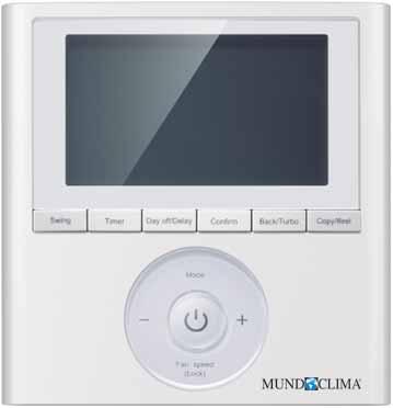
124
 and commercial range (H6).")
125 CONTROL SYSTEMS We present the full range of controls and accessories, where stands out the RG57 multifunction wireless control that allows the adjustment of functions and the parameters check in the domestic ranges (H6 and H7) and commercial range (H6). It also highlights the new wired control (with weekly programmer) KJR-120G with only 2 wires of connection and without polarity.
126 CONTROL SYSTEMS Controls Range TYPE MODEL CODE Wall Split (1 1 / Multi) DOMESTIC RANGE Cassette Multi Duct Unit COMMERCIAL RANGE Cassette Ceiling-Floor Duct WIRELESS RG57A6/BGE CL except H5A YKR-H/002E C L except H6 y H7 RM05/BG(T)E-A CL RM02A/BGE-A CL WIRED KJR-120G/TF-E CL KJR-29B1/BK-E CL except H5A KJR-86C-E CL except H5A KJR-12B/DP(T)-E CL except H5A KJR-120B/BKP-E CL KJR-120C/BW-E CL KJR-120C/TF-E CL with CL / except H5A KJR-120F1/BMK-E CL KJRM-120D/BMK-E CL CENTRALIZED CCM30/BKE CL with CL / except H5A CCM15 CL with CL / except H5A INTEGRAL IMM4 CL CL CL CL with CL / except H5A 124
127 CONTROL SYSTEMS High Capacity Duct Column INDUSTRIAL RANGE VARIABLE FLOW RATE FAN COILS UNITS WATER CHILLER MVD Wall Cassette Ceiling-Floor High Pressure Duct MUENR-H6 MUEN-H6 except HG with CL CL with CL CL except HG with CL CL with CL CL except HG with CL with CL except HG with CL with CL except HG with CL with CL only 3 pipes system except HG except HG with CL with CL except HG with CL with CL
128 CONTROL SYSTEMS TYPE MODEL CODE Wall Split (1 1 / Multi) DOMESTIC RANGE Cassette Multi Duct Unit COMMERCIAL RANGE Cassette Ceiling-Floor Duct BMS (BUILDING MANAGEMENT SYSTEM) CCM08/E CL with CL / except H5A LONGW64/E CL with CL / except H5A CCM18A/N CL with CL / except H5A MD-AC-MBS-1 CL with CL / except H5A KJRM-120D/BMK-E (Modbus) MD-AC-KNX CL CL CL CL with CL / except H5A IS-IR-KNX-1i CL WIFI OSK102 CL except H5A WF-60A1 CL TADO CO MOMIT COOL CO ACCESSORIES Multi function module CL except H5A AHUKZ FCUKZ LC LC LC CL CL KJR-150A/M-E CL with CL / except H5A DTS634 / DTS636 CL MD-NIM10 CL KJR-32B CL CCM02/E CL JC-02 CL except H5A Connector ON/OFF CL CL CL CL
129 CONTROL SYSTEMS Controls Range High Capacity Duct Column INDUSTRIAL RANGE VARIABLE FLOW RATE FAN COILS UNITS WATER CHILLER MVD Wall Cassette Ceiling-Floor High Pressure Duct MUENR-H6 MUEN-H6 except H6 and H6A except Duct High Pressure and 100% Air Ext. with CL94974 with CL94974 except HG with CL94974 with CL94974 except HG except HG with CL CL with CL CL with CL CL with CL CL only Maxi V5X and Mini >19kW except HG with CL with CL in Mini up to 18 kw with CL only Mini up to 18 kw in Mini up to 18 kw with CL in Mini up to 18 kw with CL except HG 127
130 CONTROL SYSTEMS WIRELESS RG57A6/BGE (Code CL ) FEATURES - Single wireless control - Follow Me Function (ifeel) - Silence function - Self Clean function - Daily timer - Function setting - Parameter query COMPATIBLE WITH RANGE DOMESTIC H7, H6 (1), H6M Series COMMERCIAL H6 Series (2) (1) Except Portable. (2) Except Column and High Capacity Duct YKR-H/002E (Code CL ) FEATURES - Single wireless control - Follow Me Function (ifeel) - Self Clean function - Daily timer COMPATIBLE WITH RANGE DOMESTIC H5A Series RM05/BG(T)E-A (Code CL ) FEATURES - Single wireless control - Daily timer - MVD units routing COMPATIBLE WITH RANGE COMMERCIAL INDUSTRIAL HIGH CAPACITY DUCT Series MVD Series INDUSTRIAL HYDRONIC FAN COILS Series (1) (1) Except Cassette HG, in Floor/Ceiling and High Pressure Duct with CL CL
 (1) Except Cassette HG, in Floor/Ceiling and High Pressure Duct with CL 94")
131 CONTROL SYSTEMS Wireless RM02A/BGE-A (Code CL ) FEATURES - Single wireless control - Follow Me Function (ifeel) - Auto mode for 3 pipe MVD system - Daily timer - MVD indoor units routing COMPATIBLE WITH RANGE COMMERCIAL INDUSTRIAL HIGH CAPACITY DUCT Series MVD Series INDUSTRIAL HYDRONIC FAN COILS Series (1) (1) Except Cassette HG, in Floor/Ceiling and High Pressure Duct with CL CL
 COMMERCIAL H6 Series (2) (1) Except Split Wall (2)")
132 CONTROL SYSTEMS WIRED KJR-120G/TF-E (Code CL ) FEATURES - Wired control up to 16 indoor units grouped - Follow Me Function (ifeel) - Weekly timer (4 complete periods) - Ability to block - Memory function - Displays error codes - Bi-directional - Connection with 2 wires without polarity COMPATIBLE WITH RANGE DOMESTIC H6M Series (1) COMMERCIAL H6 Series (2) (1) Except Split Wall (2) Except High Capacity Conduit and Column KJR-29B1/BK-E (Code CL ) FEATURES - Individual wired control of indoor units - Follow Me Function (ifeel) - Touch keys - Daily timer - MVD indoor units routing - Built-in infrared receiver - Memory function - Cleaning filter reminder - Ability to block - Unidirectional - 4-wire connection COMPATIBLE WITH RANGE DOMESTIC COMMERCIAL INDUSTRIAL H7, H6 (1), H6M Series H7 and H6 (2) Series MVD Series INDUSTRIAL HYDRONIC FAN COILS Series (3) (1) Except Portable Unit (2) Except Column (3) Except Cassette HG, in Floor/Ceiling and High Pressure Duct with CL
, H6M Series COMMERCIAL H7 and H6 Series (2) INDUSTRIAL MVD Series INDUSTRIAL HYDRONIC FAN")
 - Daily timer - Unidirectional - 5-wire connection COMPATIBLE WITH RANGE DOMESTIC H7, H6 (1), H6M Series COMMERCIAL H7 and H6 Series (2)")
133 CONTROL SYSTEMS Wired KJR-86C-E (Code CL ) FEATURES - Simplified individual indoor unit wiring control for hotels - Without mode change key, the mode change is made by pressing two keys together - Memory function - Unidirectional - 4-wire connection COMPATIBLE WITH RANGE DOMESTIC H7, H6 (1), H6M Series COMMERCIAL H7 and H6 Series (2) INDUSTRIAL MVD Series INDUSTRIAL HYDRONIC FAN COILS Series (3) (1) Except Portable Unit (2) Except Column (3) Except Cassette HG, in Floor/Ceiling and High Pressure Duct with CL94974 KJR-12B/DP(T)-E (Code CL ) FEATURES - Individual wired control of indoor units - Follow Me Function (ifeel) - Daily timer - Unidirectional - 5-wire connection COMPATIBLE WITH RANGE DOMESTIC H7, H6 (1), H6M Series COMMERCIAL H7 and H6 Series (2) INDUSTRIAL MVD Series INDUSTRIAL HYDRONIC FAN COILS Series (3) (1) Except Portable Unit (2) Except Column (3) Except Cassette HG, in Floor/Ceiling and High Pressure Duct with CL
 (1) Only 3 pipes system KJR-120C/BW-E (Code) CL 92 946)")
134 CONTROL SYSTEMS Wired KJR-120B/BKP-E (Code CL ) FEATURES - Individual wired control of indoor units - Touch keys - Daily timer - Memory function - Cleaning filter reminder - Ability to block - Auto mode for 3 pipe MVD system - Displays error codes - Bi-directional - 4-wire connection COMPATIBLE WITH RANGE INDUSTRIAL MVD Series (1) (1) Only 3 pipes system KJR-120C/BW-E (Code) CL ) FEATURES - Individual wired control of indoor units - Weekly timer (4 time periods) - Memory function - Ability to block - Displays error codes - Bi-directional - 4-wire connection COMPATIBLE WITH RANGE COMMERCIAL INDUSTRIAL HIGH CAPACITY DUCT Series MVD Series INDUSTRIAL HYDRONIC WALL FAN COILS and CASSETTE Series (1) (1) Except Cassette HG. KJR-120C/TF-E (Code CL ) FEATURES - Individual wired control of indoor units - Follow Me Function (ifeel) - Weekly timer (8 complete periods) - Memory function - Ability to block - Displays error codes - Bi-directional - 4-wire connection COMPATIBLE WITH RANGE DOMESTIC WALL SPLIT H7 Series (1), H6 (1) and H6M (1) (1) With CL


135 CONTROL SYSTEMS Wired KJR-120F1/BMK-E (Code CL ) FEATURES - Individual cable control for MUENR-H6 chillers - Touch keys - Daily timer - Memory function - Ability to block - Displays error codes - Bi-directional - Built-in power adapter - 3-wire connection COMPATIBLE WITH RANGE INDUSTRIAL HYDRONIC MUENR-H6 Water Chiller Series KJRM-120D/BMK-E (Code CL ) FEATURES - Wired control of up to 16 MUEN-H6T chillers - Touch keys - Daily timer - Memory function - Ability to block - Displays error codes - Bi-directional - Built-in power adapter - 3-wire connection COMPATIBLE WITH RANGE INDUSTRIAL HYDRONIC MUEN-H6T Water Chiller Series 133

136 CONTROL SYSTEMS CENTRALIZED CCM30/BKE (Code CL ) FEATURES - Centralized control of up to 64 indoor units - Touch keys - Daily timer - Memory function - Possibility to block individual controls - Possibility of locking the operation mode - Displays error codes - Emergency ON / OFF by contactor - It allows to check the evaporation / condensation temperature of the indoor units - Cleaning filter reminder - Combinable with CCM15 central control - Compatible with CCM08 / E (BACnet) interface - Installation to build-in - Installation box in optional surface (CL ) COMPATIBLE WITH RANGE DOMESTIC H7 (1), H6 (1), H6M (1) Series COMMERCIAL H7 and H6 Series (2) INDUSTRIAL MVD Series INDUSTRIAL HYDRONIC FAN COILS Series (3) (1) Except Portable, in Wall Split with CL (2) Except Column (3) Except Cassette HG, in Floor/Ceiling and High Pressure Duct with CL94974 CENTRALIZED CONTROLLER CONNECTION 64 uts. max. CENTRALIZED CONTROL CCM 134

 (1) Except Portable, in Wall Split with CL 94 383 (2) Except Column (3) Except Cassette HG, in floor/ceiling and high pressure duct with")
137 CONTROL SYSTEMS Centralized CCM15 (Code CL ) FEATURES - Centralized WEB and APP control up to 64 indoor units - Weekly timer - Memory function - Possibility to block individual controls - Ability to block: Mode, temperature and speed - Displays error codes - Cleaning filter reminder - Combinable with CCM30 central control COMPATIBLE WITH RANGE DOMESTIC H7 (1), H6 (1), H6M (1) Series COMMERCIAL H7 and H6 Series (2) INDUSTRIAL MVD Series INDUSTRIAL HYDRONIC FAN COILS Series (3) (1) Except Portable, in Wall Split with CL (2) Except Column (3) Except Cassette HG, in floor/ceiling and high pressure duct with CL94974 Max
 - Possibility to enter the building plans (in AutoCAD) to easy management -")

 - Automatic backup of the system (2GB SD card) - Multi-language (English,")
138 CONTROL SYSTEMS INTEGRAL IMM4 FEATURES - Integral solution for total control of up to 1024 indoor units; 256 MVD outdoor units or 64 MVD independent cooling systems - WEB control via IP or via software - Easy operation, intuitive operation screen - Use of users for access (user, administrator, technical service) - Possibility to enter the building plans (in AutoCAD) to easy management - Annual calendar of programming, with 4 daily patterns and 10 actions in each pattern - Possibility of limiting the temperature adjustment of indoor units - It allows to block the local control and / or the way of operation of the indoor units - Control of consumption of each MVD unit according to the parameters of operation: time, temperatures, etc. (A wattmeter CL is required in each MVD outdoor unit) - Generation of reports with the operating history (daily, weekly, monthly) - Displays system error codes - Emergency stop - Alarm signal - Possibility of sending an SMS in case of failure in the system (it is necessary to install an additional SMS modem) - Automatic backup of the system (2GB SD card) - Multi-language (English, Spanish, Italian, French, German, Russian and Chinese) - Control software included - Not compatible with centralized CCM controls Example of connections: IP / Ethernet Local PC (IMM4) Units A/C Internet Firewall Router Long distance PC (IMM4) VPN CL CL CL CL IMM4 Control up to 256 indoor units, 64 outdoor units MVD or 16 independent cooling systems MVD IMM4 Control up to 512 indoor units, 128 outdoor units MVD or 32 independent cooling systems MVD IMM4 Control up to 768 indoor units, 192 outdoor units MVD or 48 independent cooling systems MVD IMM4 Control up to 1024 indoor units, 256 outdoor units MVD or 64 independent cooling systems MVD Operation screen: COMPATIBLE WITH RANGE DOMESTIC H7 (1), H6 (1), H6M (1) Series COMMERCIAL H7 and H6 Series (2) INDUSTRIAL MVD Series (1) Except Portable, in Wall Split with CL (2) Except Column 136
 - Allows the WEB control without having to be connected to a BMS network")
 Max. 4 Systems Max.")
 FEATURES - BMS interface for connecting units to a LonWorks system - Can control up to 64 indoor units - Not compatible with centralized CCM controls - It allows to")
139 CONTROL SYSTEMS BMS (Building Management System) CCM08/E (Code CL ) FEATURES - BMS interface for connecting units to a BACnet system - It can control up to 256 indoor units or 128 MVD outdoor units, as it has 4 communication ports, each port can control 64 indoor units or 32 MVD outdoor units (via CCM02 / E control) - Allows the WEB control without having to be connected to a BMS network and without need of any additional software - It allows to control and visualize: ON / OFF of the units Operating mode Setpoint and ambient temperatures Fan Speed Swing Individual control lock Error codes BMS or WEB Function (optional) Max. 4 Systems Max. 64 UI COMPATIBLE WITH RANGE DOMESTIC H7 (1), H6 (1), H6M (1) Series COMMERCIAL H7 and H6 Series (2) INDUSTRIAL MVD Series (1) Except Portable, in Wall Split with CL (2) Except Column Max. 64 UI LonGW64/E (Code CL ) FEATURES - BMS interface for connecting units to a LonWorks system - Can control up to 64 indoor units - Not compatible with centralized CCM controls - It allows to control and visualize: ON / OFF of the units Operating mode Setpoint and ambient temperatures Fan Speed Error codes COMPATIBLE WITH RANGE DOMESTIC H7 (1), H6 (1), H6M (1) Series COMMERCIAL H7 and H6 Series (2) INDUSTRIAL MVD Series Max. 64 UI (1) Except Portable, in Wall Split with CL (2) Except Column 137

 INDUSTRIAL MVD Series Max.")
140 CONTROL SYSTEMS BMS (Building Management System) CCM18A/N (Code CL ) FEATURES - BMS interface for connecting units to a MODBUS system (TCP/IP and RTU) - It can control up to 64 indoor units and 4 MVD outdoor units of the same system - Allows the WEB control without having to be connected to a BMS network and without need of any additional software - Not compatible with centralized CCM controls - It allows to control and visualize: ON / OFF of the units Operating mode Setpoint and ambient temperatures Fan Speed Error codes COMPATIBLE WITH RANGE DOMESTIC H7 (1), H6 (1), H6M (1) Series COMMERCIAL H7 and H6 Series (2) INDUSTRIAL MVD Series Max. 64 UI (1) Except Portable, in Wall Split with CL (2) Except Column MD-AC-MBS-1 (Code CL ) FEATURES - BMS interface for connecting units to a MODBUS system (RTU) - Each gateway can control a single unit - Connection to terminals X and Y - Requires external power 12V dc COMPATIBLE WITH RANGE DOMESTIC H7 (1), H6 (1), H6M (1) Series COMMERCIAL H7 and H6 Series (2) INDUSTRIAL MVD Series (3) INDUSTRIAL HYDRONIC FAN COILS Series (4) (1) Except Portable, in Wall Split with CL (2) Except Column and High Capacity Duct. (3) Except High Pressure Duct and 100% External Air (Capacity> 16 kw). (4) Except Cassette HG, in floor/ceiling and high pressure duct with CL KJRM-120D/BMK-E(MODBUS) (Code CL ) FEATURES - Wired control and BMS interface to connect up to 16 MUEN-H6T chillers to a MODBUS (RTU) system - Same functions as KJRM-120D/BMK-E COMPATIBLE WITH RANGE INDUSTRIAL HYDRONIC MUEN-H6T Water Chiller Series 138

 Except Column, in High Duct Capacity CL 94 792 can not be used (3) Except High Pressure Duct and 100% Outdoor Air (capacity> 16 kw) the CL 94 792 can not be used IS-IR-KNX-1i (Code CL")
 * Except Cassette HG, in Floor/Ceiling and High Pressure Duct with CL 94")
141 CONTROL SYSTEMS BMS (Building Management System) MD-AC-KNX FEATURES - BMS interface for connecting units to a KNX system - The different gateways available allow us to control from a single unit up to 64 units - Not compatible with centralized CCM controls CL CL CL Interface MD-AC-KNX-1B for only one unit Interface MD-AC-KNX-16 for up to 16 units Interface MD-AC-KNX-64 for up to 64 units COMPATIBLE WITH RANGE DOMESTIC H7 (1), H6 (1), H6M (1) Series COMMERCIAL H7 and H6 Series (2) INDUSTRIAL MVD Series (3) (1) Except Portable, in Wall Split with CL (2) Except Column, in High Duct Capacity CL can not be used (3) Except High Pressure Duct and 100% Outdoor Air (capacity> 16 kw) the CL can not be used IS-IR-KNX-1i (Code CL ) FEATURES - BMS interface for connecting units to a KNX system - Each gateway can control a single unit - Compatible with most air conditioners that have an infrared receiver COMPATIBLE WITH RANGE DOMESTIC All the series COMMERCIAL All the series INDUSTRIAL MVD Series INDUSTRIAL HYDRONIC FAN COILS Series (1) * Except Cassette HG, in Floor/Ceiling and High Pressure Duct with CL CL
 in the domestic range.")


 Wifi module is required by indoor unit.")
142 CONTROL SYSTEMS WIFI OSK102 (Code CL ) FEATURES - WIFI module to control Split type of wall units (H6, H6M and H7) in the domestic range. - ON / OFF operation. - Selection of operation mode. - Adjustment of target temperature. - Selection of fan speed. - ECO mode activation. - Horizontal blade adjustment. - Weekly timer, it schedule the starts and stops from the equipment weekly. - Heating function to 8 C, if you are not home and the room temperature es less than 8 C, the equipment will start automatically in heating. - Adjustable night mode, it sets the desired temperature variations during the night. - Checking function, it allows to see if the equipment has a problem and which is the problem. COMPATIBLE WITH RANGE DOMESTIC WALL SPLIT H7 Series, H7, H6 and H6M Notes: (1) In all cases (Split 1x1 or Multi Split) Wifi module is required by indoor unit. (2) In every user account multiple equipments can be registered and in that way to monitor them. (3). Each unit can only be registered in one user account. Download application Installation NetHome Plus Insert Operating screen Functions screens Night mode function Checking function 140


143 CONTROL SYSTEMS WIFI WF-60A1 (Code CL ) FEATURES - Wired WIFI module specially designed to control duct type equipment. - Allows to operate the equipment in conjunction with the KJR-120G / TF-E Wired Control. COMPATIBLE WITH RANGE DOMESTIC H6M Series (1) COMMERCIAL H6 Series (2) (1) Only Duct (2) Except Cassette, Column and High Capacity and Column TADO (Code CO ) FEATURES - Universal WIFI module for connecting air conditioning units to your WIFI network - Unique module that does not need to connect via cable to the router to control an air conditioning unit - Are required as much WIFI modules as air conditioner units to be controlled - Compatible with most air conditioners that have an infrared receiver - Main functions: Geolocation Weather forecast Easy assembly Humidity and temperature sensor Infrared transmitter IT MAKES SMART ANY AIR CONDITIONER! COMPATIBLE WITH RANGE DOMESTIC All the series COMMERCIAL All the series INDUSTRIAL MVD Series INDUSTRIAL HYDRONIC FAN COILS Series (1) (1) Except Cassette HG, in Floor/Ceiling and High Pressure Duct with CL CL
, each Start Kit gateway can control up to 20 WIFI modules -")
 (1) Except Cassette HG, in Floor/Ceiling and High Pressure Duct")
144 CONTROL SYSTEMS WIFI MOMIT COOL (Code CO ) FEATURES - Universal WIFI module for connecting air conditioning units to your WIFI network - Main module Starter Kit, which includes gateway to connect via RJ45 cable to the router and WIFI module to control an air conditioning unit - Additional modules available (CO ), each Start Kit gateway can control up to 20 WIFI modules - Compatible with most air conditioners that have an infrared receiver - Main functions: Geolocation Weather forecast Easy assembly Humidity and temperature sensor Infrared transmitter and receiver COMPATIBLE WITH RANGE DOMESTIC All the series COMMERCIAL All the series INDUSTRIAL MVD Series INDUSTRIAL HYDRONIC FAN COILS Series (1) (1) Except Cassette HG, in Floor/Ceiling and High Pressure Duct with CL CL
 - It has an input to perform ON / OFF by contact and a free alarm signal output free of power - Bracket included to fix it on the battery of the indoor")
 to units. outdoor MVD to 2 pipes (Mini V4 +> 19kW and Maxi V5X). - Individual box capacity from 9kW up to 56kW.")
 (1) Only Maxi V5X and Mini >19kW")
145 CONTROL SYSTEMS ACCESSORIES MULTI-FUNCTION (Code CL ) FEATURES - Connects Wall Splitters (H6, H6M and H7) from the domestic range to centralized CCM controls and to the wall controller with KJR-120C / TF-E weekly programmer (CL ) - It has an input to perform ON / OFF by contact and a free alarm signal output free of power - Bracket included to fix it on the battery of the indoor unit COMPATIBLE WITH RANGE DOMESTIC WALL SPLIT H7 Series, H7, H6 and H6M AHUKZ-B (Code LC ) FEATURES - It allows to connect air treatment units (UTA) or air conditioners with direct expansion battery (DX) to units. outdoor MVD to 2 pipes (Mini V4 +> 19kW and Maxi V5X). - Individual box capacity from 9kW up to 56kW. - Up to 4 boxes can be connected in parallel to increase capacity up to a maximum of 224 kw. - Each AHUKZ-B box includes: Control system Electronic expansion valve Thermometers Wired remote control KJR-29B COMPATIBLE WITH RANGE INDUSTRIAL MVD Series (1) (1) Only Maxi V5X and Mini >19kW Outdoor Units MVD Indoor Units MVD SPECIFICATIONS: AHUKZ connection kit Air treatment unit (DX) Model AHUKZ-01B AHUKZ-02B AHUKZ-03B Code LC LC LC Power supply V ~ Hz ~ 50 / ~ 60 Capacity kw 14 (9 ~ 20) 28 (20.1 ~ 36) 56 (37 ~ 56) Connection pipes Liquid inlet mm 7.9 (5/16") 12.7 (1/2") 15.9 (5/8") Liquid outlet mm 7.9 (5/16") 12.7 (1/2") 15.9 (5/8") Dimensions Net (W x H x D) mm 350x150x375 Gross (W x H x D) mm 420x240x
 communication.")


146 CONTROL SYSTEMS Accessories FCUKZ (Code CL ) FEATURES - Control kit for any Fan coil unit on the market without built-in control board. - Flexible installation, can be installed next to the fan coil unit, on the wall or on the suspended ceiling. - Allows connection to centralized CCM control. - It allows MODBUS (RTU) communication. - It has an input to perform ON / OFF by contact and an alarm signal output. - It allows to regulate: 3 fan speeds Hydraulic circuit valves The condensate pump An auxiliary electrical resistance - Each FCUKZ box includes: Control system Thermometers NEW COMPATIBLE WITH RANGE INDUSTRIAL HYDRONIC All FAN COIL uts. without electronics (1) (1) For example Floor/Ceiling and High Pressure Duct. Centralized control Modbus communication 64 m max. 64 m max. Centralized controller CCM SPECIFICATIONS: Model FCUKZ-03 FCUKZ-04 Code (kit without remote control) CL CL Code (kit with wired remote control KJR-29B1 / BK-E) LC LC Application system 2 Pipes 4 Pipes Power supply V/Ph/Hz / 1 / / 1 / Operation range Room temperature C Inlet water temp. C Temp. precision C ± 1 ± 1 Dimensions (W x H x D) mm 296 x 66 x x 66 x 212 Weight kg

 (1) Except Portable, in Wall Split with CL 94 383 (2) Except Column (3) Except Cassette HG, in floor/ceiling and high pressure duct with CL94974 Receiver Unit")

 (1) in Mini up to")
147 CONTROL SYSTEMS Accessories KJR-150A/M-E (Code CL ) FEATURES - Kit for group control of up to 16 indoor units - Allows control of indoor units that are connected in a group with a single wired control KJR-29B - Each KJR-150A / M-E kit includes: Main module with XYE communication wired remote control KJR-29B Infrared receiver to connect the wired control or use a wireless controller COMPATIBLE WITH RANGE DOMESTIC H7 (1), H6 (1), H6M (1) Series COMMERCIAL H7 and H6 Series (2) INDUSTRIAL MVD Series INDUSTRIAL HYDRONIC FAN COILS Series (3) (1) Except Portable, in Wall Split with CL (2) Except Column (3) Except Cassette HG, in floor/ceiling and high pressure duct with CL94974 Receiver Unit Indoor #0 Unit Indoor + #1 Unit Indoor + #N (N<16) DTS634 / DTS636 (Code CL ) FEATURES - Digital wattmeter for MVD outdoor units - Allows to calculate the consumption of each outdoor unit - If unified with the integral control IMM4, it performs the consumption control of each indoor unit of the MVD system - Possibility to visualize the consumption by the control CCM02 / E or the own integral control IMM4 - One wattmeter should be installed in each outdoor unit, even in cooling systems formed by several outdoor units, always install a wattmeter per unit - To connect it to the Mini MVD V4 + units between 8 and 18kW, the MD-NIM10 module is needed COMPATIBLE WITH RANGE INDUSTRIAL MVD Series (1) (1) in Mini up to 18 kw with CL
.")
148 CONTROL SYSTEMS Accessories MD-NIM10 (Code CL ) FEATURES - Module to be able to connect the digital wattmeter (OAE ports) to the Mini MVD V4 + units between 8 and 18kW. - It also allows connection of the central control of outdoor units CCM02 / E and alarm signal KJR-32B (ports K1K2E). COMPATIBLE WITH RANGE INDUSTRIAL MVD Series (1) (1) only Mini up to 18kW KJR-32B (Code CL ) FEATURES - MVD outdoor unit alarm controller module, generates an alarm signal (230Vac) when there is an error in the equipment. - Can control up to 32 outdoor units or 8 independent cooling systems. COMPATIBLE WITH RANGE COMMERCIAL HIGH CAPACITY DUCT Series INDUSTRIAL MVD Series (1) (1) in Mini up to 18 kw with CL CCM02/E (Code CL ) FEATURES - Centralized control up to 32 outdoor units or 8 MVD independent cooling systems. - Allows monitoring the MVD outdoor units. - If the outdoor unit adds the wattmeter (CL ), it shows the total consumption of the unit. COMPATIBLE WITH RANGE COMMERCIAL HIGH CAPACITY DUCT Series INDUSTRIAL MVD Series (1) (1) in Mini up to 18 kw with CL
, H6M Series COMMERCIAL H6 Series (2) (1) Except Portable Unit (2) Except High Capacity Conduit and Column CONNECTOR ON/OFF (Code CL 94 831-833) FEATURES")
149 CONTROL SYSTEMS Accessories JC-02 (Code CL ) FEATURES - Test and Diagnostic Tool - It allows you to view the parameters of the unit, the history of errors, set the frequency of the compressor, etc. COMPATIBLE WITH RANGE DOMESTIC H7, H6 (1), H6M Series COMMERCIAL H6 Series (2) (1) Except Portable Unit (2) Except High Capacity Conduit and Column CONNECTOR ON/OFF (Code CL ) FEATURES - Connector with 2 wires that allows to make a remote ON / OFF by contact in the units that do not include this function COMPATIBLE WITH RANGE INDUSTRIAL MVD Series (1) INDUSTRIAL HYDRONIC FAN COILS Series (2) (1) Cassette, Wall and Floor/Ceiling (2) Only Cassette MUCS-W7 Code CL94831 CL94832 CL94833 CL97176 For equipments MVD-Q4/DHN1-A3; MUCS-14/16-W7 MVD-Q4/DHN1-D; MUCS-20/24/36-W7 MVD-G/DHN1-M MVD-DL/DHN1-C 147
150 CONTROL SYSTEMS Functions Summary Max. Unit to Control ON / OFF Mode selection Fan Speed Selection Selection Room temperature Swing function Sleep function Silence function Self Clean function Eco mode WIRELESS RG57A6/BGE CL YKR-H/002E CL RM05/BG(T)E-A CL RM02A/BGE-A CL WIRED KJR-120G/TF-E CL KJR-29B1/BK-E CL KJR-86C-E CL KJR-12B/DP(T)-E CL KJR-120B/BKP-E CL KJR-120C/BW-E CL KJR-120C/TF-E CL KJR-120F1/BMK-E CL KJRM-120D/BMK-E CL CENTRALIZED CCM30/BKE CL CCM15 CL
151 CONTROL SYSTEMS Keyboard lock Mode lock Temperature lock Infrared Receiver Follow Me Function (ifeel) Auto function (Only 3 pipes system) Daily timer Weekly timer Clock Displays error codes Units routing MVD Cleaning reminder Filters Memory function Function setting Query function Bi-directional Number of connection threads

152

153 AEROTHERM RANGE Aerotherm V17 is provided in Monobloc and Bibloc versions. In the Monobloc version the hydronic unit of hydro / gas exchange is located in the same outdoor unit. The Bibloc version, on the other hand, has the external unit and the hydronic indoor unit separated, offering more flexibility. Both versions can get the energy label A ++, so they are equipment with the highest performance of energy efficiency contributing significantly to limit an impact on the environment.

154 MUNDOCLIMA Aerotherm V17 Series AEROTHERM RANGE Aerotherm V17 is provided in Monobloc and Bibloc versions. In the Monobloc version the hydronic unit of hydro / gas exchange is located in the same outdoor unit. The Bibloc version, on the other hand, has the external unit and the hydronic indoor unit separated, offering more flexibility. Both versions can get the energy label A ++, so they are equipment with the highest performance of energy efficiency contributing significantly to limit an impact on the environment. RANGE OF PRODUCTS Capacity (kw) MONOBLOC General view 220~240V-1Ph Capacity (kw) BIBLOC General view 220~240V-1Ph Outdoor unit Hydronic box (4-8 kw) Hydronic box (1Ph,10-16 kw) 152
155 AEROTHERM V17 Monobloc Model High Efficiency & Total Solution AEROTHERM RANGE DC INVERTER TECHNOLOGY GUARANTEES THE OPTIMUM OPPORTUNITY, ROBUSTNESS AND EFFICIENCY Energy efficiency Monobloc range COP COP test according to: Outdoor temperature 7 C/ Water temperature 35 C EER EER test according to: Outdoor temperature 35 C/ Water temperature 18 C COP COP test according to: Outdoor temperature 7 C/ Water temperature 55 C EER EER test according to: Outdoor temperature 35 C/ Water temperature 7 C PROVIDES 80% POWER AT -7 C THANKS TO THE LARGE SURFACE OF THE EXCHANGER AND THE POWERFUL COMPRESSOR Fins heat exchanger Copper pipe Ø9.5 with corrugated surface to optimize exchange efficiency. Hydrophilic aluminum fins, ideals for fast drainage and anti-mold. Anti corrosion coating. Blue coating to ensure durability. Hydronic Unit Integrated in the same unit generating sanitary hot water. Resistance included except 5 and 7 kw models, for which it is optional. Brushless DC fan motor BLDC with 100% electric control with low sound level, working in quiet mode as well as low energy consumption. DC Inverter Compressor The recent launch of our new TWIN ROTARY compressor with permanent magnets offers low sound level, wide frequency spectrum and more precision. It comes with a 100% DC frequency drive system that drastically reduces power consumption. Single rotor TWIN rotor Twin Rotary compressor High efficiency motor: - Creative design. - Neodymium HD magnets. - Concentration stator. - Wide operation frequency. Better balance and extremely low vibrations: - Twin eccentric cams. - 2 balancing weights. - High stability mobile parts: - High quality material on rollers and pallets. - Optimized technology. - Highly robust bearings. - Compact structure. 153
 Max. 25 Min. 7 Min. -5 Max.")
156 AEROTHERM RANGE Flexible operation and great comfort Monobloc Aerotherm V17 THE WEATHER AFFECTS DIRECTLY THE COMFORT With AEROTHERM V17 we have up to 32 correlation curves to choose from. Once we select the curve, the unit chooses the output temperature according to the outside temperature. Cooling mode Heating mode Operation Water outlet ( C) Max. 25 Min. 7 Min. -5 Max. 46 Operation Outdoor ( C) Operation Water outlet ( C) Max. 55 Min. 30 Min. -20 Max. 35 Operation Outdoor ( C) 2 CONTROL ZONES The temperature of each zone is separated, the control of 2 zones reduces the times between cycle and saves energy. 2 zones with control by 1 interface SHW tanks Radiator Valve 3-ways 3-way valve Circulator Zone 2 Zone 2 is controlled by the return temperature Monobloc Control panel Zone 1 Underfloor heating Zone 1 is controlled by the control panel sensor 2 zones with control by interface and thermostat Control panel Thermostat 2 Radiator SHW tanks Valve 3-ways 3-way valve Circulator Zone 2 Zone 2 is controlled by the return temperature Monobloc Thermostat 1 Zone 1 Zone 1 is controlled by the control panel sensor Underfloor heating PRIORITIES AND MULTI-MODES 60~70 C Priority mode Cooling Priority mode Heating Priority Sanitary Hot Water AUTO mode Disinfection mode Vacations mode Force SHW mode ECO Mode Comfort mode Silent mode Special functions such as purge, installation and preheating. 154
157 AEROTHERM RANGE TECHNICAL SPECIFICATIONS Monobloc Aerotherm V17 Model 7 kw 12 kw 16 kw Code SO SO SO Nominal voltage V/Ph/Hz /1/50 Heating capacity (1) Absorbed power kw Total power kw COP Heating capacity (2) Absorbed power kw Total power kw COP Cooling capacity (3) Absorbed power kw Total power kw EER Cooling capacity (4) Absorbed power kw Total power kw EER Energy efficiency Water 35 C LOT1 A++ Water 55 C LOT1 A+ Sound level Heating db(a) Cooling db(a) Dimensions (Width x Height x Depth) mm Packaging (Width x Height x Depth) mm Net/ gross weight kg 99/ / /183 Compressor Type Twin-rotary inverter Fan Motor type Brushless DC motor Air flow rate m³/h Air exchanger Finned battery Water exchanger Thermo-welded plates Water pump m Expansion tank volume L Refrigerant Expansion type Type R410A Load kg Electronic expansion valve Mounted in series kw Optional 3 3 Electric resistance Stages Power supply V/Ph/Hz /1/50 Water pipe connections inch 1" Female 1-1/4" Female 1-1/4" Female Operating temperature range Outlet water temp. range Cooling C -5~46 Heating C SHW C Cooling C 5~25 Heating C 25~60 SHW C 40~60 Nominal capacity is based on the following conditions: 1. Outdoor air temperature 7 C RH 85%. Inlet/Outlet temp. water 30/35 C. 2. Outdoor air temperature 7 C RH 85%. Inlet/Outlet temp. water 40/45 C. 3. Outdoor air temperature 35 C. Inlet/Outlet temp. water 23/18 C. 4. Outdoor air temperature 35 C. Inlet/Outlet temp. water 12/7 C. 5. The previous test temperatures come from the standards: EN14511:2013; EN14825:2013; EN50564:2011; EN12102:2011; (EU)No:811:2013; (EU)No:813:2013; OJ 2014/C 207/02:2014. HEATING MODE COOLING MODE SANITARY HOT WATER T4 Ambient temperature ( C) T1 Ambient temperature ( C) 155


158 AEROTHERM RANGE AEROTHERM V17 Bibloc model High Efficiency & Total Solution DC INVERTER TECHNOLOGY GUARANTEES THE OPTIMUM OPPORTUNITY, ROBUSTNESS AND EFFICIENCY Energy efficiency Monobloc range COP COP test according to: Outdoor temperature 7 C/ Water temperature 35 C EER EER test according to: Outdoor temperature 35 C/ Water temperature 18 C COP COP test according to: Outdoor temperature 7 C/ Water temperature 55 C EER EER test according to: Outdoor temperature 35 C/ Water temperature 7 C PROVIDES 80% POWER AT -7 C THANKS TO THE LARGE SURFACE OF THE EXCHANGER AND THE POWERFUL COMPRESSOR Fins heat exchanger Copper pipe Ø9.5 with corrugated surface to optimize exchange efficiency. Hydrophilic aluminum fins, ideals for fast drainage and anti-mold. Anti corrosion coating. Blue coating to ensure durability. Brushless DC fan motor BLDC with 100% electric control with low sound level, working in quiet mode as well as low energy consumption. DC Inverter Compressor The recent launch of our new TWIN ROTARY compressor with permanent magnets offers low sound level, wide frequency spectrum and more precision. It comes with a 100% DC frequency drive system that drastically reduces power consumption. Resistance Flow Switch Expansion tank High Efficiency Circulating Pump Plate-type heat exchanger Pressure gauge 156
159 AEROTHERM RANGE Flexible operation and great comfort Bibloc Aerotherm V17 Model THE WEATHER AFFECTS DIRECTLY THE COMFORT With AEROTHERM V17 we have up to 32 correlation curves to choose from. Once we select the curve, the unit chooses the output temperature according to the outside temperature. Cooling mode Heating mode Operation Water outlet ( C) Max. 25 Min. 7 Min. -5 Max. 46 Operation Outdoor ( C) Operation Water outlet ( C) Max. 55 Min. 30 Min. -20 Max. 35 Operation Outdoor ( C) 2 CONTROL ZONES The temperature of each zone is separated, the control of 2 zones reduces the times between cycle and saves energy. 2 control zones with 1 user interface Control panel SHW tanks Hydronic indoor unit Radiator Zone 2 Zone 2 is controlled by the return temperature Circulator Outdoor unit 3-way valve 3-way valve Zone 1 Zone 1 is controlled by the control panel sensor 2 control zones with 1 user interface and thermostat Underfloor heating Control panel Hydronic indoor unit Thermostat 2 Radiator Zone 2 SHW tanks Zone 2 is controlled by the return temperature Circulator Outdoor unit 3-way valve 3-way valve Zone 1 Zone 1 is controlled by the control panel sensor Thermostat 1 Underfloor heating PRIORITIES AND MULTI-MODES 60~70 C Priority mode Cooling Priority mode Heating Priority Sanitary Hot Water AUTO mode Disinfection mode Vacations mode Force SHW mode ECO Mode Comfort mode Silent mode Special functions such as purge, installation and preheating. 157
160 AEROTHERM RANGE TECHNICAL SPECIFICATIONS: HYDRONIC INDOOR UNIT Bibloc Aerotherm V17 Model Model from 4 to 8 kw from 10 to 16 kw Code SO SO Type Outlet water temp. range Heating Cooling Heating and cooling Low C 25 ~ 55, default 35 Height C 35 ~ 60, default 45 Low C 7 ~ 25, default 7 Height C 18 ~ 25, default 18 Sanitary Hot Water C 40 ~ 60, default 45 Nominal voltage V/Ph/Hz /1/ /1/50 Dimensions (Width x Height x Depth) mm Packaging (Width x Height x Depth) mm Net/ gross weight kg 51/57 54/60 Output connection mm DN25 Safety valve MPa 0.3 Water volume L 5 Drain connection mm Ø16 Water circuit Expansion tank Plate heat exchanger Volume L 3 Maximum pressure MPa 0.8 Preloading pressure MPa 0.15 Type Thermo-welded plates Volume L Circulator m Cooling circuit Electrical resistance Liquid mm Ø9.5 Gas mm Ø15.9 Power kw Stages 2 2 Nominal voltage /1/ /1/50 Rated capacity is based on the following conditions: 1. Condition 1: Heat mode outdoor temperature 7 C and outlet water 35 C with T at 5 C. Cool mode outdoor temperature 35 C and water outlet 18 C with T at 5 C. 2. Condition 2: Heat mode outdoor temperature 7 C and outlet water 35 C with T at 5 C. Cool mode outdoor temperature 35 C and water outlet 7 C with T at 5 C. 3. The above data are from the reference standard EN HEATING MODE COOLING MODE SANITARY HOT WATER T4 Ambient temperature ( C) T1 Ambient temperature ( C) 158
161 AEROTHERM RANGE TECHNICAL SPECIFICATIONS: OUTDOOR UNIT Bibloc Aerotherm V17 Model Model 6 kw 8 kw 10 kw 12 kw 14 kw 16 kw Code SO SO SO SO SO SO Nominal voltage V/Ph/Hz /1/50 Total power kw Heating capacity (1) Absorbed power kw COP Total power kw Heating capacity (2) Absorbed power kw COP Total power kw Cooling capacity (3) Absorbed power kw EER Total power kw Cooling capacity (4) Absorbed power kw EER Energy Water 35 C LOT1 A++ efficiency Water 55 C LOT1 A+ A++ A+ A++ A++ A+ Sound Heating db(a) level Cooling db(a) Dimensions (Width x Height x Depth) mm x1327x400 Packaging (Width x Height x Depth) mm Net/ gross weight kg 60/72 76/88 99/112 Compressor Type Twin-rotary inverter Fan Air exchanger Pipeline connection Type Brushless DC motor Air flow rate m³/h Liquid Gas Piping distance Installation height Finned battery Type Cooling copper External diameter mm Ø9.5 Type Cooling copper External diameter mm Ø15.9 Min. m 2 Maximum m Outdoor ut. over m Outdoor ut. under m Refrigerant Type R410A Load kg Expansion type Electronic expansion valve Operating temperature range Cooling C -5~46 Heating C -20~35 Hot water C -20~43 Nominal capacity is based on the following conditions: 1. Outdoor air temperature 7 C RH 85%. Inlet/Outlet temp. water 30/35 C. 2. Outdoor air temperature 7 C RH 85%. Inlet/Outlet temp. water 40/45 C. 3. Outdoor air temperature 35 C. Inlet/Outlet temp. water 23/18 C. 4. Outdoor air temperature 35 C. Inlet/Outlet temp. water 12/7 C. 5. The previous test temperatures come from the standards: EN14511:2013; EN14825:2013; EN50564:2011; EN12102:2011; (EU)No:811:2013; (EU)No:813:2013; OJ 2014/C 207/02:

162 AEROTHERM RANGE HEAT PUMP FOR SHW MONOBLOCK System NEW 150 liters Copper condenser, spirally attached to the outside of the accumulator, it ensures that the refrigerant can never be in contact with water. Distributed asymmetrically over the whole height of the accumulator, with greater surface in the lower cap, which favors a homogeneous distribution of the water temperature. E Y IJA IE IA 200L Models of 150 and 200 liters capacity: Operation with heat pump and / or resistance support, 1 or 2, for a total operation autonomy. Helical fan for free discharge. Models for 300 capacity liters: Equipped with an hydraulic exchanger to connect to a solar energy installation or to any other energy production system. Centrifugal fans that allow the conduction of condensation air, which increases the installation POSSIBILITIES and / or operation and increases performance L TECHNICAL FEATURES Model 150 L 200 L 300 L Code SO SO SO Working conditions, room temp. C -7 / 43-7 / 43-7 / L and 200 L Nominal capacity Liters Power given / consumed kw 1.85 / / / 0.83 COP Min.-max. consumption A Voltage V-Hz 230V-I-50Hz 230V-I-50Hz 230V-I-50Hz Air flow rate m³/h Sound level db(a) Dimensions (D x H) mm 568/ / /1920 Weight (net / package) kg 87/98 91/ /120 Refrigerant type / load kg R134a/0.8 R134a/1.2 R134a/1.2 XL E Y IJA IE IA 300L Hydraulic connections mm DN20 DN20 DN20 Test pressure bar Max. working pressure bar bar Water inlet/outlet temperature C 38/70 prefixed 60 38/70 prefixed 65 38/70 prefixed 65 Solar hydraulic exchanger Connections mm DN20 Tube diam / long. mm Ø22/10000 Max. pressure bar Condensation air Connection diameter mm 190 ASP mm WCLM 30 Max. ducts length m 10 Support resistance kw L Different solutions of the condensation air intakes. In all cases the maximum length will be 10 m. In the case of conducting the entrance and exit, the sum of both ducts will be equal to or less than 10 m. 300 L + hydraulic Kit 160


163 AEROTHERM RANGE HEAT PUMP FOR SHW SPLIT System The most efficient option to cover the hot water supply for home installation and for the service sector (gyms, residences, small urban hotels, etc.). It has a daily consumption of up to 3000 l / day. For the best performance it is necessary to analyze the actual demand of the place and to store enough sanitary hot water. The system consists of an air-water heat pump, which incorporates a tubular heat exchanger, liquid water, with double chamber, which ensures the tightness between the coolant and the water, even in the event of leakage. With the highest power model (7.2 kw) we can have 1000 liters at 55 C first thing in the morning, enough to meet the peak demand of approximately 35 to 40 shower services at 40 C. Installation is very simple. Insulated copper tubing connects the heat pump to the accumulator, up to a maximum distance of 5 m and a maximum level difference of 3 m, between the outdoor unit and the accumulator. The circulation pump, built-in the outdoor unit, heats the water of the accumulator as it passes through the exchanger. The temperature control is carried out by means of an electronic board built-in the outdoor unit. Double tube Refrigerant Water Tubular exchanger detail TECHNICAL FEATURES Model RSJF-50/CN1-A RSJF-72/CN1-B Code SO SO Voltage V-Hz 1-220V-50Hz 1-220V-50Hz Thermal capacity kw Electric power kw COP Consumption A Max. consumption A Start consumption A Air flow rate m³/h Sound level db(a) Unit dimensions (W x H x D) mm 790 x 736 x x 940 x 324 Dimens. with packaging (W x H x D) mm 905 x 807 x x 1009 x 395 Weight kg 62/66 81/86.5 Refrigerant / quantity kg R410A/1.22 R410A/1.3 Hydraulic connections DN15 DN15 Max. length m 5 5 Max. height for unit / accumulator m 3 3 Working conditions Performance tests: Outdoor temperature 7.0 / 6.0 C (dry / wet bulb); Water inlet 30 C, outlet 35 C. Operating temperatures -7 / 43 C. HOT WATER Heat Pump Diagram RSJF-50/CN1-A 161

164

165 HEAT RECOVERY UNITS ENERGETIC SAVING OF LAST GENERATION The current legislation require us, through the RITE standards, to the use of heat recovery units that guarantee a renewed air at a reduced costs.

 51 Power supply V/Hz/Phase 380/ 50/3 Recovery unit efficiency % 70 Static pressure Pa 160 Net")
166 HEAT RECOVERY UNITS ENTALPHIC RECOVERY UNIT MURE Series FEATURES - 2 operating speeds. - Structured with flat and corrugated blades. - Crossed flows. - TOTAL heat recovery up to 75%. - With great permeability. There is a tiny space between fibers in order to avoid pollution transfer. OPTIONAL Centralized controller For models 1500 (CL ) Canopy Outside suction duct Outlet air Retorno Return Air inlet Outlet air duct Return Discharge Model MURE-1500 Code CL Air flow rate m³/h 1500 Consumption W 1260 Sound level db(a) 51 Power supply V/Hz/Phase 380/ 50/3 Recovery unit efficiency % 70 Static pressure Pa 160 Net weight kg 160 Dimensions (L x W x H): mm 1500 x 540 x
 IP20, F Class (1200, 1900, 2400 and 3300 models) - Single phase and three-phase models.")
,")
.")


167 HEAT RECOVERY UNIT MU-RECO SN Series HEAT RECOVERY UNITS Heat recovery units without additional heating contribution. Motors: IP44, F Class (500, 800, 4400 and 5200 models) IP20, F Class (1200, 1900, 2400 and 3300 models) - Single phase and three-phase models. - Flow rate from 500 to 5,200 m 3 /h. - Horizontal installation. - Side panel exchangers allowing multiple combinations. FEATURES - Heat recovery with cross-flow exchanger mounted in galvanized steel boxes with internal thermal acoustic insulation made of 6 mm thick polyethylene foam (M1), configurable inlet and outlet openings with sealing. - Available with different filtration levels (G4, M5, and low load loss micro-filters F6, F7, F8 and F9, made of polypropylene). Provided with filter holders that allow mounting of one or two filters in both air directions. Versatile assembly The design of this heat recovery units allows the user to set them up on site. There are several combinations of panel exchange. This allows to place, in a great number of cases, the impulsion / suction connections directly to the installation area according to the specific requirements. Robustness High quality finishings. Aluminium framework providing high robustness. High-efficiency filters Combine up to two filters in each direction of the air. Conventional filters G4 and M5. F7 and F9 filters very low load loss, made of polypropylene. CONDENSATE WATER DRAINAGE Drain pipe that allows condensate water outlet. Easy servicing Quick access to filters from top, bottom and side part. Easy to install Single phase models with brackets for mounting on suspended ceiling. Three-phase models with feet for floor mounting. HORIZONTALS Standard Versions Conf. CH Model Standard configuration Various layouts can me made very quickly and easily by the professional installer. Sealed external terminal box Except for 500 and 900 models. Single phase models with external sealed box of terminals, IP65. Sealed box Rubber sealed joints in the tap cover and in the suction/discharge flanges providing a tight sealing. 165
168 HEAT RECOVERY UNITS TECHNICAL FEATURES Heat Recovery Unit MU-RECO SN Code Model Motor Intensity max. current Sound pressure at 3 m Power consump. 50Hz (A) Speed IP Efficiency db (A)** r.p.m. Protection %* kw 230V 230/400V Suction Discharge Distribution CL MU-RECO 500 SN 2 x x IP CL MU-RECO 900 SN 2 x x IP CL MU-RECO 1200 SN 2 x x IP CL MU-RECO 1900 SN 2 x x IP CL MU-RECO 2400 SN 2 x x IP CL MU-RECO 3300 SN 2 x x IP CL MU-RECO 4400 SN 2 x x 10.1/ IP CL MU-RECO 5200 SN 2 x x 10.1/ IP *Values for the following conditions: Outside air temperature -5 C, inside air temperature +20 C, with 80% inside RH / 70 % max. flow rate. ** Average sound pressure in free field environment. DIMENSIONS (mm) Code Model A B C D E Ø Weight (kg) CL MU-RECO CL MU-RECO CL MU-RECO CL MU-RECO CL MU-RECO CL MU-RECO CL MU-RECO CL MU-RECO
169 HEAT RECOVERY UNITS Heat Recovery Unit MU-RECO SN TYPICAL MAXIMUM SPEED CURVES: MU-RECO 500 SN MU-RECO 900 SN MU-RECO 1200 SN MU-RECO 1900 SN MU-RECO 2400 SN MU-RECO 3300 SN MU-RECO 4400 SN MU-RECO 5200 SN - qv = flow rate in m³/h. - Psf = Static pressure in Pa. P(W) = Absorbed power at the maximum speed (W). Normal dry air at 20 C and 760 mmhg mercury column. Hg. - In accordance with ISO 5801 and AMCA standards. Additional load losses Resistance: 10 Pa (all models) Water batteries 45Pa 167

170

171 AIR CURTAINS A WARM WELCOME Keeping the doors open involves a huge waste of energy in most buildings. Proper installation of an air curtain can reduce energy loss through open doors by 90%. In addition to the significant energy savings, air curtains improve the healthiness of the environment and allow you to keep the doors open even during winter, which allows the entry of customers in stores. The air curtains have a slogan: A warm welcome...


 m³/h 1,100 1,500 1,900 2,280")
 W 200 260 350 420 440 Voltage V-Hz-Ph 220-50-1 220-50-1 220-50-1 220-50-1 220-50-1 Sound level H (high) db(a) 52 53 55 57 58 L (low) db(a) 49 50 52 55 56 Net weight kg 13 15.")
172 AIR CURTAINS AIR CURTAINS SILVER Series FEATURES - Innovative design without visible hardware. - Aluminium and ABS. - Remote control and control panel. - Operation indicator. Easy to open, practical design that uses no screws on the outside deck. The stainless housing is made of high strength aluminum and high quality ABS. With unique guide bar design, which enables the production of air in all directions, being able to adapt to different environments. It can be controlled by the remote control and control panel. It has a switch for high and low speed. Provided with an optimized electric machinery, it works safely and effectively. Fine metal blades provide a better control of the airflow. Integrated design with metal side cover. Buttons with light indicator High performance, high efficiency. TECHNICAL FEATURES Model MU-ALU 09 MU-ALU 12 MU-ALU 15 MU-ALU 18 MU-ALU 20 Code EC EC EC EC EC Air flow rate H (high) m³/h 1,100 1,500 1,900 2,280 2,520 L (low) m³/h 900 1,200 1,500 1,800 2,100 Speeds Nº Remote control YES YES YES YES YES Manual control YES YES YES YES YES Consumption H (high) W L (low) W Voltage V-Hz-Ph Sound level H (high) db(a) L (low) db(a) Net weight kg Length mm Dimensions Height mm Depth mm

173 AIR CURTAINS AIR CURTAINS INOX Series FEATURES - Stainless steel housing. - Special design. - Manual controller. - Two speeds. - Ideal for saline environments. The outer casing made of stainless steel is easy to clean and offers a high resistance against fire. With unique guide bar design, which enables the production of air in all directions, being able to adapt to different environments. It has a switch for high and low speed. Provided with an optimized electric machinery, it works safely and effectively. High performance, high efficiency. TECHNICAL FEATURES Model MU-IN 12 MU-IN 15 MU-IN 18 Code EC EC EC Air flow rate H (high) m³/h 1,500 1,900 2,280 L (low) m³/h 1,200 1,500 1,800 Speed H (high) m/s L (low) m/s Remote control NO NO NO Manual control YES YES YES Consumption H (high) W L (low) W Voltage V-Hz-Ph Sound level H (high) db(a) L (low) db(a) Net weight kg Length mm Dimensions Height mm Depth mm *Max recommended installation height: 3.5 meters 171
174 AIR CURTAINS AIR CURTAINS MU-ECO Series FEATURES - Metallic casing. - Various sizes, from 90 to 150 cm. - Microprocessor control. - Remote control (see model). - High speed. Mod. Only air Mode with heating Models ONLY AIR Models HEATING Keeping the doors open involves a huge waste of energy in most buildings. Proper installation of an air curtain can reduce energy loss through open doors by 90%. In addition to the significant energy savings, air curtains improve the healthiness of the environment and allow you to keep the doors open even during winter, which allows the entry of customers in stores. The air curtains have an operating slogan: A warm welcome... TECHNICAL FEATURES ONLY AIR REMOTE CONTROL WITH HEATING ELECTRICAL SINGLE PHASE WITH HEATING ELECTRICAL THREE PHASE MU-ECO Model /6R 12/8R 15/8R 09/6R3 12/8R3 15/8R3 Code EC EC EC EC EC EC EC EC EC Air flow rate m³/h 1,020 1,360 1, ,280 1, ,280 1,670 Heating power kw Voltage V-Hz-Ph I I III Speeds Nº Applicable height m Fan power consumption W 186/ 238/ / 285/ / 381/536 96/ / /207 96/ / /207 Power consumption in heating W 6,120 7,380 9,250 6,120 7,380 9,250 Control Remote Remote and manual Remote and manual Sound level db(a) Height mm Length mm 900 1,200 1, ,200 1, ,200 1,500 Depth mm Net weight kg


175 AIR CURTAINS GREAT FLOW AIR CURTAIN MU-ECO GC Series FEATURES - Centrifugal type fan. - High efficiency design. - High air flow. - High static pressure. - Metal housing, fire resistant. - Maximum installation height: 6 m. - Easy installation. - Power supply: 220V-50HZ-1 Ph. Double shaft motor. Metallic fan. Metal fan housing. Centrifugal fan of high capacity. Metallic casing. Max recommended height 6 m. TECHNICAL FEATURES Model MU-ECO 10 GC MU-ECO 12 GC MU-ECO 15 GC Code EC EC EC Air flow rate m³/h 3,709 3,709 3,563 Motor power kw Absorbed current A Air speed m/s Sound level db(a) Height mm Length mm 1,000 1,200 1,500 Depth mm

 48 50 49 48 48 48 50 49 49 48 50 48.6 Absorbed intensity A 0.5 0.8 0.")
176 AIR CURTAINS AIR CURTAINS MU-CA Series Air speed Series 100 Series 150 Series 200 TECHNICAL FEATURES Model MU-CA 100AN 150AN 200AN 100RN3,5 100RN6 100RN9 150RN9 150RN12 200RN W9 150-W W24 Code EC Power supply V 230V II 230V II 230V II 230V II 400V III 400V III 400V III 400V III 400V III 230V II 230V II 230V II Heating power kw 3.5 3/6 4.5/9 4.5/9 6/12 9/ Speeds Air flow rate m³/h 1,420 2,675 2,744 1,384 1,384 1,295 2,545 2,500 2,600 1,623 2,812 2,890 Air outlet speed m/s Sound level db(a) Absorbed intensity A Thermal jump T 9/11/18 14/ 18/26 20/ 25/30 13/ 15/25 18/ 20/30 20/ 25/ Outdoor control (wall) Included Included Included Included Included Included Included Included Included Included Included Included Weight kg White color RAL Length mm 1,080 1,686 2,186 1,080 1,080 1,080 1,686 1,686 2,186 1,080 1,686 2,


177 AIR CURTAINS GREAT HEIGHT AIR CURTAIN MU-CA Series FEATURES - For 4-8 m doors. - Horizontal installation. Control MU-CR Series 1000 Distance/air speed Installation height TECHNICAL FEATURES Model MU-CA 1000F 1500F 1000E E E E W W50 Code EC EC EC EC EC EC EC EC Power supply V N 400+N 400+N 400+N Heating power kw 9/18 12/24 12/24 18/ Thermal jump DT 5/7/11/13 7/9/14/17 5/6/10/11 7/8/15/17 20/33 20/33 Speeds Nº Air flow rate m³/h 4100/ / / / / / / /7500 Output speed m/s Max. current consump. A Controller Optional Optional Optional Optional Optional Optional Optional Optional Sound level db(a) Weight kg

178 AIR CURTAINS AIR CURTAINS AC Series FEATURES - Horizontal installation. - Innovative design. - Steerable discharge grille. - White finish RAL The range of AC curtains has been designed with a pleasant aesthetic. The visual impact is minimal, even if performed by a floating facility glass doors. The unit provides a climate separation, while preventing the entry of foreign microorganisms and dust. The semicircular shape in white RAL9010 is certainly an added value to the interior aesthetic design of all buildings. It can be installed next to other units, allowing its use on doors of various sizes. Available in: only cooling, electrical and hydronic heating versions Driven by remote control. Remote Control Airspeed depending on height TECHNICAL FEATURES ONLY AIR WITH ELECTRIC BATTERY WITH WATER BATTERY Model AC1000HA AC1500HA AC2000HA AC1000HE9 AC1500HE12 AC2000HE18 AC1000HW12 AC5000HW18 AC2000HW24 Code EC EC EC EC EC EC EC EC EC Power supply V Heating power kw Thermal jump T 25/35 26/33 23/29 26/33 23/29 20/27 Speeds Nº Air flow rate m³/h 1850/ / / / / / / / /5000 Output Speed m/s 8.5/11 8.5/11 8.5/11 8.5/11 8.5/11 8.5/11 6.4/ / /9.4 Current A Controller Included Included Included Included Included Included Included Included Included Sound level db(a) 55/60 55/60 55/60 55/60 55/60 55/60 55/60 55/60 55/60 Weight kg High / Bottom mm 395/ / / / / / / / /350 Length mm Color RAL 9010 RAL 9010 RAL 9010 RAL 9010 RAL 9010 RAL 9010 RAL 9010 RAL 9010 RAL

 m/s m/s m/s 15 12,5 10 15 12,5 10 15 12,5 10 Air flow rate H (high) m³/h 1020 1360 1700 OUTLET AIR Sound level H (hight) L (low) db(a) db(a) 53 51 54 52 56 54 Gross weight kg 17.2 21.8 29.1 1.")
179 AIR CURTAINS AIR CURTAINS MU-EMP Series FEATURES - Specially designed for ceiling installation. - Metallic casing. - 3-speed motor. - Remote control. - Installation height: 3.5 m. Remote control Model A B MU-EMP MU-EMP MU-EMP TECHNICAL FEATURES Model MU-EMP 09 MU-EMP 12 MU-EMP 15 Code EC EC EC Unit length mm Power supply V/Ph/Hz /1/ /1/ /1/50 Motor power H (high) M (medium) L (low) W W W INLET AIR Air outlet speed H (high) M (medium) L (low) m/s m/s m/s 15 12, , ,5 10 Air flow rate H (high) m³/h OUTLET AIR Sound level H (hight) L (low) db(a) db(a) Gross weight kg Available with nominal tension and personalized frequency. 2. The pressure level is heard at 1 m distance under the air outlet. 3. Standard units are equipped with European plugs. 4. Customized plugs available. 177

180

181 DEHUMIDIFIER, HEATERS AND EVAPORATIVE UNITS MODERN AND ELEGANT DESIGN In the living and working environments, ensuring a correct humidity is not a luxury but a factor of well-being, health and productivity. Moisture control preserves from the damage caused by dry air, even on furniture and wooden floors, paintings and antiquarian objects.


182 DEHUMIDIFIERS, HEATERS AND EVAPORATIVE UNITS DEHUMIDIFIER MH Series MH-10-V5 / MH-20-V5 - Electronic control. - Adjust air flow (3 speeds). - ON/OFF Timer. - Humidity level adjustment between 35-80%. - LED Display. - Possibility to connect to continuous drain. - Water level viewer. - Incorporates wheels for easy transport. - Temperature range Operating temperature 5-35 C. - Memory function / auto-ignition. - Anti-overflow protection. - Automatic defrost. - Tank with 4 L capacity. MH-10-V5 / MH-20-V5 MH-40-V5 - Electronic control. - Memory function / auto power on. - ON/OFF Timer. - Anti-overflow protection. - Water level viewer. - Automatic defrost. - LED Display. - Incorporates wheels for easy transport. - Possibility to connect to continuous drain. - Tank with 6 L capacity. MH-40-V5 MH-60-N / MH-80-N - Modern and elegant design. - High dehumidification capacity. - High efficiency rotary compressor. - Electromechanical controller. - Possibility to connect to continuous drain. - Incorporates wheels for easy transport. - Tank with 7.2 L capacity. MH-60-N / MH-80-N TECHNICAL FEATURES Model MH-10-V5 MH-20-V5 MH-40-V5 MH-60-N MH-80-N Code HU HU HU HU HU Power supply V - Hz Absorbed power W ,150 1,350 Dehumidification liters/day* Air flow (High/Medium/Low) m³/h 150 / 120 / / 160 / / / / / 400 / / Width Dimensions Height Deep mm mm mm Weight kg Refrigerant R 134a R 134a R 410a R 410a R 410a *30 C / 80% RH


183 DEHUMIDIFIERS, HEATERS AND EVAPORATIVE UNITS WALL HEATER MUR Series Economic Series MUR - Infrared remote control. - Manual control button in the unit. - Power 220 V - 50 Hz. - 2 powers selectable 1000 W W. - Operation indicator light. - Timer 0.5 to 7.5 hours. - Dimensions: 453 x 182 x 113 mm. - Fixed fins. Code CE MUR-LUXUS Luxus Series - Temperature control. - Air Swing function. - Remote controller for infrared rays. - Manual controller of the unit. - Power 220 V - 50 Hz. - 2 powers selectable W W. - Timer 0.5 to 7.5 hours. - Dimensions: 618 x 208 x 127 mm. - Steerable fins. - Front digital indication from temperature. Code CE It is perfect for open rooms. Offices, bathrooms, kitchens, etc. 181
. - Two stages heating: 1000W/2000W. - Ability to add ice cubes. - Three ventilation speeds. - Wheels for better mobility. - Low sound level.")
184 DEHUMIDIFIERS, HEATERS AND EVAPORATIVE UNITS PORTABLE EVAPORATIVE AIR CONDITIONER MUEV-ECO Series FEATURES - Remote control and control panel. - Water curtain system free of germs. - Antibacterial tank (8 liters). - Two stages heating: 1000W/2000W. - Ability to add ice cubes. - Three ventilation speeds. - Wheels for better mobility. - Low sound level. - Low consumption LED display. - 8 h Timer Refreshes Humidifies 4 FUNTIONS Heats Purifies ITS OPERATION The evaporative cooling is one of the most efficient methods to save energy and cool a room. Your power consumption is less than the alternatives. It is also considered environmentally friendly because the process does not require chemical agents that could damage the ozone layer. Based on the physical phenomenon of evaporation, it is only necessary a small amount of water to start the process. The hot air is pushed to pass through an high efficiency and long lasting antigerm fabric, through this fabric circulate water in a close circuit. The outside temperature is reduced by the evaporative process, and so is the cooled air introduced into the building by the fan. In this way we get... ADVANTAGES OF THE EVAPORATIVE SYSTEM - Very low electrical consumption. - Reduced water consumption due to its circulation in a closed-loop. - It delivers 100% fresh air without impurities. - Low sound level. - Speed control at will. - Easy servicing. HEALTH The conditioners clean the air, using 100% of fresh and new air. It does not dry the air as conventional ventilation equipments. The humidity is maintained, resulting beneficial to our body, animals, plants... Especially recommended for allergic and asthmatic persons, as those who suffer from migraines or have dust or mites allergy. PROVED EFFICIENCY The decrease of temperature in the room depends on the amount of water absorbed by air according to: - Relative humidity on the air. - Evaporation capacity of water (depending on the temperature and hardness). - Ventilation capacity of the location. TECHNICAL FEATURES Model MUEV-2000-ECO Code CE Voltage AC V/50Hz Consumption in cooling 70W Consumption in heating 1000/2000W Electric protection Type II Air volume 350 m³/h Net weight 6.5 kg Tank capacity 8 L Dimensions (LxWxH) 370 x 320 x

185 DEHUMIDIFIERS, HEATERS AND EVAPORATIVE UNITS PORTABLE EVAPORATIVE AIR CONDITIONER MUEV-C7 Series NEW FEATURES - Portable evaporative air conditioner recommended to refresh rooms until 17 m². - Ideal for dry environments. - Temperature drop from 5~15 C depending on the humidity level of the air. - Air inlet all around the unit. - Easy detachable which allows easy cleaning and maintenance. - Includes wheels for better mobility. - Automatic blade swinging. - Remote control included. OPERATION The evaporative cooling is one of the most efficient methods to save energy and cool a room. Your power consumption is less than the alternatives. Moreover, it is also considered environmentally friendly because the process does not require chemical agents that could damage the ozone layer. Based on the physical phenomenon of evaporation, it is only necessary a small amount of water to start the process. The hot air is pushed to pass through an high efficiency and long lasting antigerm fabric, through this fabric circulate water in a close circuit. The outside temperature is reduced by the evaporative process, and so is the cooling air process. TECHNICAL FEATURES Model MUEV-1500-C7 Code HU Power supply V / Hz 230 / 50 Air Flow (High / Medium / Low) m³/h 1500 / 1200 / 900 Consumption W 108 Sound level db(a) 58 Water tank volume (liters) L 11.5 Continuous use time with full water tank hours 7.5 ~ 10 Cooling pads Units 4 Recommended surface m² 17 Dimensions (W x H x D) mm 360 x 798 x 360 Weight kg 8.5 Warning: 1. Data and specifications are subject to changes without previous notice. 183

 and discover our new way")
186 Check the website for more information about our MUNDOCLIMA product range (Domestic, commercial and industrial air conditioning) and discover our new way of providing: information support contact languages
Models: 12 and 18. Models: 24 to 60
 SPLIT CASSETTE TYPE MUCSR-H8 Series SCOP 4.0 Models: 12 and 18 RG57B2/BGE Included (CL 94 982) Models: 24 to 60 Design 360 Thanks to the 360 panel design, the air is more evenly distributed. Drainage pump
FULL DC INVERTER SYSTEMS INDIVIDUAL AND MODULAR CONSTRUCTION FLEXIBLE COMBINATIONS AIR CONDITIONING COMMERCIAL AIR CONDITIONERS SDV4 2014
 FULL DC INVERTER SYSTEMS INDIDUAL AND MODULAR CONSTRUCTION FLEXIBLE COMBINATIONS COMMERCIAL AIR CONDITIONERS SDV4 2014 AIR CONDITIONING 1 WELCOME TO THE WORLD OF SINCLAIR AIR CONDITIONERS Company operation
Multizone Multi Split systems
 19 Multizone Multi Split systems Features and Benefits 2 Room 3 Room 4 Room 5 Room 6 Room RAM-36NP2A RAM-53NP2A RAM-53NP3A RAM-68NP3A RAM-70NP4A RAM-90NP5A RAM-130NP6A Nominal Cooling Capacity (kw) 3.6
40KQV. Direct expansion split system Inverter Cassette. Nominal Cooling capacity: 4,85-12,40 kw Nominal Heating capacity: 5,10-13,00 kw
 LLOYD'S REGISTER QUALITY ASSURANCE Direct expansion split system Inverter Cassette I S O 9 00 1 40KQV Nominal Cooling capacity: 4,85-12,40 kw Nominal Heating capacity: 5,10-13,00 kw 40KQV cassette belongs
Midea VRFs/ Midea V5X. Timothy Huang Senior Engineer
 Midea VRFs/ Midea V5X Timothy Huang Senior Engineer VRF Product Overview General Features V5X Key Technologies V5X VRF product strategy VRF line-up Fresh air solutions Selection software Unique Innovations
Ducted medium static pressure monosplit DC Inverter
 +VAV (Variable Air Volume) Ducted medium static pressure monosplit Unique solutions 20 19 22 For 18-24-30-36 23 24 18 A ++ RC08W 2016 Ducted medium static pressure monosplit FUNCTIONS > Ducted line available
Unique solutions FLEXY MATCH FLEXY MATCH FLEXY MATCH R410A FLUID AUTO AUTO CLEAN/DRY SLEEP MODE LOW BATTERY INDICATION WIRED CONTROL OPTION
 2013 Catalogue Monosplit DCI HJD Unique solutions FLEXY MATCH ADVANCED CONTROL OPTIONS HIGH WALL MONO & PREMIUM MULTI FLEXY MATCH STERIONIZER q High wall line available in capacities 2.5 up to 7.5 kw.
Cool with the sun and save 60% of your power
 Cool with the sun and save 60% of your power Saves up to 60% of your electrical power Same prices as non solar systems (incl. panel!) Top technology with attractive indoor units Heat pump for cooling and
CEILING CONCEALED SPLIT SYSTEM C SERIES
 CEILING CONCEALED SPLIT SYSTEM C SERIES Microprocessor Controlled ith the microprocessor controlling the operation, the ACC model can offer comfortable room conditions according to the needs of the user.
modular multi intelligent, environmental and versatile
 modular multi intelligent, environmental and versatile system overview 2-pipe R407C heat pump VRF system From 8 to 46 HP in one piping system (19 steps) Active leak detection system option Up to 40 indoor
Technical Support Division GD CHIGO HEATING & VENTILATION EQUIPMENT CO., LTD.
 Technical Support Division 2012.10 1 1. External appearance 2. Nomenclature 3. Specifications 4. Dimensions 5. Service space 6. Piping diagram 7. Wiring diagram 8. Capacity tables 9. Electric characteristics
YCZ HIGH WALL RESIDENTIAL MULTISPLIT DUO/TRIO/QUATTRO/CINCO
 YCZ RESIDENTIAL MULTISPLIT DUO/TRIO/QUATTRO/CINCO q Multi line available in four capacities from 5.2 up to 10.5 kw. q DC Inverter and sine wave compressor drive technology. q Match with high wall, ducted,
PRICE LIST
 PRICE LIST 2014-2015 100% PRODUCTION 100% PANASONIC TESTING AND QUALITY ASSURANCE RESEARCH & DEVELOPMENT AND DESIGN SERVICE PROVIDER PRO Club: the professional website of Panasonic Panasonic has an impressive
Heat pumps for swimming pools
 Heat pumps for swimming pools Full range of heat pumps for indoor and outdoor swimming i pools The best heating for your pool Reliable and effective Made in Europe www.certikinpoolsindia.net THE CHALLENGE:
HPR. Heat recovery units. from 700 to m³/h R410A HIGH EFFICIENCY WITH ENTHALPY EXCHANGER AND BUILT-IN HEAT PUMP SYSTEM
 1 Lmf Clima 216 FERRARO GROUP HPR Heat recovery units HIGH EFFICIENCY WITH ENTHALPY EXCHANGER AND BUILT-IN HEAT PUMP SYSTEM from 7 to 23. m³/h Supporting structure in extruded aluminium profiles and curtain
Ductless. MRV-S (Mini VRF) Product Brochure. Higher Comfort, Haier Living. rev 01/01/2018
 Product Brochure. Higher Comfort, Haier Living. rev 01/01/2018") Higher Comfort, Haier Living 2018 MRV-S (Mini VRF) Product Brochure rev 01012018 Ductless HAIER MRV MILESTONES MRV-S KEY FEATURES Haier is one of the leading producers of HVAC products, having the capacity
Higher Comfort, Haier Living 2018 MRV-S (Mini VRF) Product Brochure rev 01012018 Ductless HAIER MRV MILESTONES MRV-S KEY FEATURES Haier is one of the leading producers of HVAC products, having the capacity
Indoor Console. Slim Design This is only 199mm thick, the slimmest on the market. Its slim design easily integrates the unit into your décor.
 Indoor Console Slim Design This is only 199mm thick, the slimmest on the market. Its slim design easily integrates the unit into your décor. Black Display Functional art, the touch screen display is elegant
III. Roof Mount AC Mobile Climate Control 19 MCC Reference Manual 2014
 III. Roof Mount AC Mobile Climate Control 19 MCC Reference Manual 2014 III.1. Large Roof Mount PN: 89-3037 Roof Mount Unit Eco 136 Parallel roof mount Air-conditioning and ventilation systems The Eco 136
VRF. For Commercial and Light Commercial
 118 VRF For Commercial and Light Commercial 119 SOLUTIONS SMALL OFFICES Fujitsu General provides perfect total air conditioning systems that take into account energy saving, low noise, comfortable airflow,
Y-Flow TCHEY-THHEY
 Y-Flow TCHEY-THHEY 245-4450 Cooling capacity: 41.2 448.8 kw - Heating capacity: 50.23 515.49 kw Applications with well water, water mains or geothermal probes Integrated MASTER/SLAVE control HT65 version
DC INVERTER VRF SYSTEMS C-VRF
 DC INVERTER VRF SYSTEMS C-VRF Index VRF System Overview 4 C-VRF 9 Advantages 10 Benefits For Users 14 Benefits For Installers 18 C-VRF MINI 27 Advantages 28 Indoor Units 33 Indoor Units Line Up 34 Indoor
COMMERCIAL // HEATING AND COOLING SYSTEMS EVERY OFFICE MATTERS
 2010 COMMERCIAL // HEATING AND COOLING SYSTEMS EVERY OFFICE MATTERS COMMERCIAL WELCOME TO COMMERCIAL RANGE Welcome to Commercial range. Welcome to healthier air. A range which confi rms its commitment
Bosch Climate 5000 Ductless Minisplit System
 Engineering Submittal Sheet Overview and Certifications [single zone only] Standard Features and Field Installed Accessories Standard Features R-410A chlorine-free refrigerant with pre-charge for line
Flex Series. Modular Air-cooled Chillers and Heat Pumps Cooling Capacity kw Heating Capacity kw
 Flex Series Modular Air-cooled Chillers and Heat Pumps Cooling Capacity 38-329 kw Heating Capacity 47-354 kw 1 Trane Flex Series Modular air/water chillers and heat pumps units with axial fans and scroll
ceiling wall AWYZ14LB/18LB With the world's first self-cleaning filter system
 ceiling wall Large and wide airflow High efficiency Low noise Large centre display Easy maintenance Inverter options Automatic filter cleaning options Easy-to-use remote controller AWYZ14LB/18LB With the
VRF Indoor Unit 50Hz. Type: Wall Mounted M Series Wall Mounted S Series
 VRF Indoor Unit 50Hz Type: Wall Mounted M Series Wall Mounted S Series Contents 01 Wall Mounted M Series 20 Wall Mounted S Series MCAC-VTSM-2016-05 Wall Mounted M Series Wall Mounted M Series 1. Features...
PRODUCT LINEUP VRF For LIGHT COMMERCIAL & RESIDENTIAL, COMMERCIAL
 IRSTGE Systems can be designed to create an air conditioning solution to suit most buildings requirements. IRSTGE Systems can be designed to effectively provide an air conditioning solution from a large
UMXCA/UMXCBA ECVA/ECVBA
 OUTDOOR UNITS Models: 801.1 1001.1 1201.1 1501.1 1602.2 2002.2 2402.2 3002.2 3502.2 4002.2 4502.2 Cooling Capacities: from 25,9 kw to 134,7 kw Heating Capacities: from 27,3 kw to 142,4 kw INDOOR UNITS
PREMIUM INVERTER DUCTED AIR CONDITIONING
 PREMIUM INVERTER DUCTED AIR CONDITIONING PANASONIC LEADS THE WAY Ducted Air Conditioning Specialists With more than 30 years of experience, exporting to more than 120 countries around the world, Panasonic
something new in the air Technical Bulletin
 something new in the air Technical Bulletin 2 Air Leaf 2 Air Leaf 3 Innova is a company operating in the renewable energy sector and develops advanced climatic comfort systems for every season. The technological
R410A TECHNICAL MANUAL. Inverter Single Split Series Air Conditioner. FTK-J, FTXN-J Series. Cooling only & Heatpump [50Hz] TM-5WMY-J-ST-A2
![R410A TECHNICAL MANUAL. Inverter Single Split Series Air Conditioner. FTK-J, FTXN-J Series. Cooling only & Heatpump [50Hz] TM-5WMY-J-ST-A2](/thumbs/87/97223604.jpg "R410A TECHNICAL MANUAL. Inverter Single Split Series Air Conditioner. FTK-J, FTXN-J Series. Cooling only & Heatpump [50Hz] TM-5WMY-J-ST-A2") R410A TECHNICAL MANUAL Inverter Single Split Series Air Conditioner FTK-J, FTXN-J Series Cooling only & Heatpump [50Hz] TM-5WMY-J-ST-A2 Table of Contents Table of Contents Nomenclature...1 Indoor...1 Outdoor...1
R410A TECHNICAL MANUAL Inverter Single Split Series Air Conditioner FTK-J, FTXN-J Series Cooling only & Heatpump [50Hz] TM-5WMY-J-ST-A2 Table of Contents Table of Contents Nomenclature...1 Indoor...1 Outdoor...1
INVERTER DUCTED SYSTEMS
 INVERTER DUCTED SYSTEMS What you ll find inside: DC Twin-Rotary Compressor Inverter Ducted advantages Controllers Product specifications Energy Efficient Powerful Operation Flexible Application 1 About
AHN 064 to 304 EHN/CHN 064 to 304
 u Horizontal Packaged and Split Air Conditioners AHN 64 to 34 EHN/CHN 64 to 34 6. to 29.2 kw 6.4 to 29.4 kw Engineering Data Manual EDM AECHN-A.1GB Date : June 28 Supersedes : None Technical Description
42GW. Hydronic Cassette Fan Coil Units PRODUCT SELECTION DATA INSTALLATION, OPERATION AND MAINTENANCE INSTRUCTIONS EASY INSTALLATION
 PRODUCT SELECTION DATA EASY INSTALLATION INSTALLATION, OPERATION AND CENTRAL AIR DIFFUSION MAINTENANCE INSTRUCTIONS LOW ENERGY CONSUMPTION IMPROVED COMFORT ELEGANT AIR INLET GRILLE EXTREMELY QUIET OPERATION
Air conditioning. Residential and Light Commercial
 Fans Air Handling Units Air Distribution Products Air Conditioning Fire Safety Air Curtains and Heating Products Tunnel Fans Air conditioning Residential and Light Commercial Systemair Trust We consider
M1 TYPE SLIM VARIABLE STATIC PRESSURE HIDE AWAY CONCEALED DUCT
 VRF SYSTEMS M TYPE SIM VARIABE STATIC PRESSURE IDE AWAY CONCEAED DUCT The ultra slim M type is one of the leading products of its type in the industry. With a depth of only mm it provides greater flexibility
INVERTER MULTI SYSTEMS 38QUS*-1
 INVERTER MULTI SYSTEMS 38QUS*-1 Ultimate cooling and heating comfort with the maximum flexibility C H A RAC TE RI S TI C S DC Inverter technology with twin rotary compressor and DC fan motor for quitter
Technical Support Division GD CHIGO HEATING & VENTILATION EQUIPMENT CO., LTD.
 Technical Support Division 2013.12 1 1. External appearance 2. Nomenclature 3. Specifications 4. Dimensions 5. Service space 6. Piping diagram 7. Wiring diagram 8. Capacity tables 9. Electric characteristics
1. Features Specifications Dimensions Service Spaces Piping Diagrams Wiring Diagrams...
 MCAC-VTSM-2013-08 1. Features... 264 2. Specifications... 265 3. Dimensions... 268 4. Service Spaces... 272 5. Piping Diagrams... 273 6. Wiring Diagrams... 274 7. Capacity Tables... 276 8. Electrical Characteristics...
Hi-Wall Inverter Split System. Efficient, effective and comfortable cooling and heating where you need it
 Hi-Wall Inverter Split System Efficient, effective and comfortable cooling and heating where you need it The Convenient Solution Feature Packed The Brivis Hi-Wall Inverter Split System has a pleasing,
Chiller. AQL/AQH 40 to 75. Air Cooled Water Chillers Cooling Only and Heat Pump Engineering Data Manual to 77.2 kw to 75.
 Chiller AQL/ to 75 Air Cooled Water Chillers Only and Heat Pump Engineering Data Manual.0 to 75.8 kw 39.9 to 77.2 kw Outstanding Strength Points R410A Refrigerant. New simpler refrigerant circuit layout.
Engineering Data Book
 Engineering Data Book Contents Specifications 2 Dimensions of Indoor 3 and outdoor units Indoor unit Outdoor unit Wiring diagrams 6 RAS-05BKV-E RAS-07BKV-E RAS-05BAV-E RAS-07BAV-E Sensible capacity table
SOLAR AIR CONDITIONER
 NIN TM 24 Clean Energy Co. LTD 12 FL. ZEN ORLD TOER RJDMRIROD, PTHUMN 10330 BNGKOK, THILND Tel: +66 (0)99 291 65 49 email: 24@24cleanenergy.com SOLR IR CONDITIONER Clean Energy, Everywhere 01 02 CONTENTS
From domestic to commercial applications you ll find the detail you need to pinpoint which ActronAir system is most appropriate for your needs.
 PRODUCT RANGE PRODUCT Contents RANGE Wall Hung Split Systems Variable Capacity Pages 4- Split Ducted Standard Cycling Pages 6-11 The ActronAir range of air conditioners provides a solution for most applications.
Ceiling Concealed Series FDMRN-AV1K. 50Hz. Preliminary
 Ceiling Concealed Series FDMRN-AV1K 50Hz Nomenclature Main Benefits Engineering and Physical Data Electrical Data Capacity Tables Outline and Dimensions Electrical Connection Refrigerant Piping Nomenclature
Hi-Wall Inverter Split System. Cooling and heating, exactly where and when you need it
 Hi-Wall Inverter Split System Cooling and heating, exactly where and when you need it Save on Running Costs 2.6kW & 3.2kW 4.2kW & 5.0kW 7.0kW & 8.0kW High Efficiency Along with running cost savings due
Air Conditioning System
 For continual product development, LG reserves the right to change specifications without notice. LG MULTI V Air Conditioning System 00 Air Conditioning System 00 Air Conditioning System Enjoy a clean
Ductless F L EXIBIL ITY IS F R EEDOM. Fl ex Fit d uc t l ess system. Higher Comfort, Haier Living
 Ductless F L EXIBIL ITY IS F R EEDOM I n t ro d uc in g t h e H a ie r Fl ex Fit d uc t l ess system A What is FlexFit? FlexFit is a top-of-the-line modular system that allows for optimal ductless pairings
MODEL: DCT 35 INV-Si DCT 50 INV-Si DCT 70 INV-Si DCT 100 INV-Si DCT 140 INV-Si DCT 170 INV-Si
 MODEL: DCT 35 INV-Si DCT 50 INV-Si DCT 70 INV-Si DCT 100 INV-Si DCT 140 INV-Si DCT 170 INV-Si Part 1 General Information.. 1 Part 2 Indoor Units. Part 3 Outdoor Units. Part 5 Control... Part 6 Control
Hitachi Multizone Heat Pump Air Conditioning
 Cooling 1.5 13.2 Heating 1.5 14.4 Hitachi Heat Pump Air Conditioning Giving you complete control Zone control that s fast, efficient and clean Imagine being able to rapidly adjust the comfort levels in
Air-Cooled Liquid Chiller with integrated hydraulic module
 Air-Cooled Liquid Chiller with integrated hydraulic module Cooling only: CGAN 200-250 - 300-400 - 450-490 - 500-600 - 700-800 - 900-925 Reversible: CXAN 200-250 - 300-400 - 450-490 - 500-600 - 700-800
UTA STANDARD. Ductable units. Range. Air handling unit with high available static pressure. NEW Eco-Design Filter. V3000 control Fresh air management
 Ductable units NEW Eco-Design Filter Air handling unit with high available static pressure V3000 control Fresh air management The range of air handling units is designed for suspended ceiling heating and
DUCTED AIR CONDITIONING YEAR ROUND COMFORT FOR YOUR HOME
 DUCTED AIR CONDITIONING YEAR ROUND COMFORT FOR YOUR HOME PANASONIC LEADS THE WAY Ducted Air Conditioning Specialists With more than 30 years of experience, exporting to more than 120 countries around the
Residential multisplit Duo/Trio/Quattro/Cinco DC Inverter
 YCZ Residential multisplit Duo/Trio/Quattro/Cinco DC Depending on combination HKD COMPATIBLE WITH HND CBD DCD A ++ XAD 2016 YCZ Residential multisplit Duo/Trio/Quattro/Cinco DC COMPATIBLE WITH HIGH WALL
VLH 504 to Air-to-Water Reverse Cycle Heat Pumps. 126 to 294 kw. 133 to 307 kw
 Air-to-Water Reverse Cycle Heat Pumps VLH 504 to 1204 126 to 294 kw 133 to 307 kw Technical Brochure TM VLH-N.3GB Date : June 2005 Supersedes : TM VLH-N.2GB/07.04 Specifications Advantages Range extension
Ductless Split Systems
 Ductless Split s Right Product for the Right Application September 2014 Ductless Split s Right Product for the Right Application Single-Zone s Multi-Zone s (up to five rooms) High Wall High Wall, Cassette,
Others ( 50Hz areas ) ADVANCED SUBJECT DATE: Sep 12 PRODUCT NEWS Launching of new RPI-(2.0~6.0)FSN4E ducted indoor units series.
 ADVANCED SUBJECT DATE: Sep 12 PRODUCT NEWS Launching of new RPI-(2.0~6.0)FSN4E ducted indoor units series.") PRODUCT S Launching of new RPI-(2.0~6.0)FSN4E ducted indoor units series. PAGE 1/7 Suary This Advanced Products News introduces the launching of new RPI-(2.0~6.0)FSN4E ducted indoor units series driven
PRODUCT S Launching of new RPI-(2.0~6.0)FSN4E ducted indoor units series. PAGE 1/7 Suary This Advanced Products News introduces the launching of new RPI-(2.0~6.0)FSN4E ducted indoor units series driven
TECHNICAL GUIDE R410a SPLIT SYSTEM 1.5 to 5.0 NOMINAL TONS
 Version.MDT-2016.T3.103 TECHNICAL GUIDE R410a SPLIT SYSTEM 1.5 to 5.0 NOMINAL TONS FEATURES AND BENEFITS COMPRESSOR: Compressors are protected with internal temperature and current overloads. An internal
Driving and Connecting Globally. Fan Coil Unit. Model : PHW-K Size : 510CMH~2720CMH. Made in Taiwan
 Driving and Connecting Globally Fan Coil Unit : PHW-K Size : 510CMH~2720CMH Made in Taiwan Features Superior low-height design. Stainless steel drain pan for condensate and corrosion protection. Flexibe-reverse
Ductless Split Systems
 Ductless Split s Right Product for the Right Application Ductless Split s Right Product for the Right Application 1:1 2:1 to 5:1 High Wall High Wall, Cassette, Underceiling 2:1 to 5:1 High Wall Up to 23.0
RESIDENTIAL & LIGHT COMMERCIAL AIR CONDITIONERS 2015 / 2016 EVERY BUILDING MATTERS
 RESIDENTIAL & LIGHT COMMERCIAL AIR CONDITIONERS 2015 / 2016 EVERY BUILDING MATTERS A Better Life, A Better World As we move towards our Centenary in 2018, our new brand slogan encapsulates Panasonic s
RENEWABLE RESOURCES FOR RENEWABLE LIFE
 TM Trillion Customers, Maximum Services RENEWABLE RESOURCES FOR RENEWABLE LIFE Solar Refrigerator Solar AC www.teramaxindia.com HYBRID AC/DC SOLAR AIR CONDITIONER The system priority consume DC power from
DC INVERTER DUCTED AIR CONDITIONERS
 DC INVERTER DUCTED AIR CONDITIONERS DC Inverter Ducted Air Conditioners Technology. With over 5% of revenue invested in research and development programs, Hitachi has developed world leading technologies
Product Brochure 2018
 Product Brochure 2018 2018 Brand Story - 2 - HEALTH Air Filter COMFORT Auto mode heating or cooling. and other materials. Wi-Fi Control Compatible to the Internet Evaporator self-cleaning ENERGY DRED Soft
COMFORT FOR LIFE DUCTLESS WALL & FLOOR MOUNTED HIGH-EFFICIENCY HEAT PUMP 20 SEER UP TO 12.5 HSPF UP TO 13 EER INVERTER, VARIABLE-SPEED COMPRESSOR
 20 SERIES - ENHANCED CAPACITY DUCTLESS WALL & FLOOR MOUNTED HIGH-EFFICIENCY HEAT PUMP 20 SEER UP TO 12.5 HSPF UP TO 13 EER INVERTER, VARIABLE-SPEED COMPRESSOR COMFORT FOR LIFE www.daikincomfort.com "I'm
Indirect evaporative air conditioning 100% outside air FACTORY INSTALLATION (CW-160)
") FACTORY INSTALLATION (CW-160) Indirect evaporative air conditioning 100% outside air About Climate Wizard Climate Wizard s unique indirect evaporative heat exchange core provides hyper-efficient cooling
FACTORY INSTALLATION (CW-160) Indirect evaporative air conditioning 100% outside air About Climate Wizard Climate Wizard s unique indirect evaporative heat exchange core provides hyper-efficient cooling
technical sales guide - 60Hz Ducted Split Units HIGH AMBIENT OPERATION 52 UPTO
 technical sales guide - 60Hz Taurus R Ducted Split Units UPTO HIGH AMBIENT OPERATION 52 O C Page CONTENTS Nomenclature.. 2 Description. 3 Features.. 3 Product Data. 4 Condensing Unit Cooling Performance
LG HVAC SOLUTION. LG Electronics. Distributed by. Copyright 2017 LG Electronics. All rights reserved.
 2 0 1 7 2017 LG HVAC SOLUTION LG Electronics http://www.lg.com http://partner.lge.com Distributed by Copyright 2017 LG Electronics. All rights reserved. ULTIMATE INVERTER COMPRESSOR As the core technology
Residential. Hot Water. Commercial. XRV Multi-System. Controls. Technical courses
 2012 Hokkaido is a brand of Termal Group, based in Italy and present in the international market, which for 30 years has been a leader in the air conditioning sector throughout Europe. It is a brand that
Air Conditioning. Air conditioning. Residential and Light Commercial
 ir Conditioning ir conditioning Residential and Light Commercial Systemair Trust We consider your trust in us as a supplier an important goal. It is always included in our work on all levels and in all
NEW. Wall controls. YFCN Fan Coil Units. Technical Guide - for internal distribution only
 NEW Wall controls Fan Coil Units www.euroventcertification.com www.certiflash.com Technical Guide for internal distribution only CONTENTS Construction Page 4 s Page 5 Dimension, Weight, Water content Page
Fan coil unit NBS 100/150
 Fan coil unit /150 Ferdinand Schad KG Steigstraße 25-27 D-78600 Kolbingen Telephone +49 (0) 74 63-980 - 0 Fax +49 (0) 74 63-980 - 200 info@schako.de www.schako.de Contents Description...3 Advantages...3
SUBMITTAL DATA - OUTDOOR UNIT VEP075N432K VRF HEAT PUMP
 VEP075N432K Job Name: Location: Schedule No.: System Designation: Engineer: Architect: Date: For: Reference Approval Review Construction FEATURES Two-pipe heat pump Hinged electrical box for ease of maintenance
Model RAS-25YHA2 RAS-35YHA3 RAS-50YHA2 RAS-60YHA2 RAS-70YHA2 RAS-80YHA2
 2-8 GENERAL DATA 2.3. INVERTER SERIES 2.3.1. INVERTER (RAS-25YHA2/35YHA3/50YHA2/60YHA2/70YHA2/80YHA2) Model RAS-25YHA2 RAS-35YHA3 RAS-50YHA2 RAS-60YHA2 RAS-70YHA2 RAS-80YHA2 Power Supply From Outdoor Unit
NEW PRODUCTS EFFICIENT SOLUTIONS PRICE LIST
 NEW PRODUCTS 2018 2019 EFFICIENT SOLUTIONS PRICE LIST DOMESTIC P. 8 PANASONIC: ECO & SMART IDEAS FOR A SUSTAINABLE LIFESTYLE COMMERCIAL P. 40 Panasonic Green Innovation Company. We will make the environment
D M S 760 C01 A A 1 1
 CONTENTS Description Features Options Available Selection Method Product Data Cooling Performance Data (85 F Ambient Cooling Performance Data (95 F Ambient) Cooling Performance Data (105 F Ambient)..............................
Superior Performance in Extreme Temperature Submittal Data: SAP09HP230V1A
 Superior Performance in Extreme Temperature Submittal Data: 9,000 BTU/H Wall Mounted Heat- Pump System Job Name Location Date Purchaser Engineer Submitted To For Unit Designation Schedule No. GENERAL FEATURES
PRK PREVIEW. System. OZONE FRIENDLY R-407C Series. Inverter Heat Pump Series Heat Recovery Series PLUS Series (Heat Pump)
") PRK 00-04 PREVIEW System OZONE FRIENDLY R-407C Series Inverter Heat Pump Series Heat Recovery Series PLUS Series (Heat Pump) 3DUW#4 2XWGRRU#8QLWV 111111111111111111111111111111111111111111111111111111111111111111111
PRK 00-04 PREVIEW System OZONE FRIENDLY R-407C Series Inverter Heat Pump Series Heat Recovery Series PLUS Series (Heat Pump) 3DUW#4 2XWGRRU#8QLWV 111111111111111111111111111111111111111111111111111111111111111111111
Fans Air Handling Units Air Distribution Products Fire Safety Air Curtains and Heating Products Water terminals SYSCOIL. Centrifugal fan coil units
 Fans Air Handling Units Air Distribution Products Fire Safety Air Curtains and Heating Products Water terminals SYSCOIL Centrifugal fan coil units SYSCOIL Fan coil units Compact, slim fan coil units. Available
Technical Service Manual. TVR LX Systems Medium Static Pressure Duct Units with DC Fan Motor V/50-60Hz/1ph
 Technical Service Manual TVR LX Systems Medium Static Pressure Duct Units with DC Fan Motor 220-240V/50-60Hz/1ph August 20 Medium Static Pressure Duct Unit With DC Fan Motor 1. Features...2 2. Specifications...4
New ECOi Electric 2 and 3 pipe VRF systems. 2006/7 Range. All round air conditioning by
 New ECOi Electric 2 and 3 pipe VRF systems 2006/7 Range 1 All round air conditioning by ECOi the next generation of 2 and 3 pipe electric SANYO is justifi ably proud of being renowned for developing unique
Carisma The Ultra Quiet Fan Coil
 Carisma The Ultra Quiet Fan Coil Air Conditioning Carisma / CRR Fan Coil Units Quality management systems SO 900 Cert. n 0545/4 www.euroventcertification.com www.certiflash.com CONTENTS Construction ()
The Mr Slim Inverter Cassette Range
 The Mr Slim Inverter Cassette Range Mr Slim Inverter Cassette Range Ideal for use in small offices, retail and leisure The Mr Slim Inverter Cassette Range offers customers all the features and benefits
VRF Mini Series 50Hz. Commercial Air Conditioners Commercial Air Conditioner Division Midea Group
 Coercial Air Conditioners 16 VRF Mini Series 50Hz Midea CAC After-service Application Midea CAC News Application Coercial Air Conditioner Division Midea Group Add.: West Region of Midea Coercial Air Conditioner
Four-Way Ceiling Cassette
 Benefits of Multi F Systems Individual zone control Operating ranges of 14 F to 118 F in cooling and 0 F to 64 F in heating Quiet and comfortable environment Safer and easier installation with Cost efficient
HIGH-EFFICIENCY MINI-SPLIT AIR CONDITIONERS AND HEAT PUMPS
 UP TO 20 SEER PERFORMANCE HIGH-EFFICIENCY MINI-SPLIT AIR CONDITIONERS AND HEAT PUMPS Energy Star ratings are dependent upon conditions beyond equipment installation. To make certain your HVAC equipment
V33B High Efficiency 360 Cassette Indoor Models - 60HZ
 PRODUCT SPECIFICATIONS Low-sound, high efficiency cassette, encased in galvanized steel offers 360 airflow for immediate, equal distribution of wide-range cooling and heating. Cassette has motor-driven
High Static Pressure Duct Fan Coil Unit
 MCAC-KTSM-2012-03 High static pressure ducted FCU High Static Pressure Duct Fan Coil Unit 1. Introduction... 2 2. Nomenclature... 2 3. Product Schedule... 3 4. External Appearance... 3 5. Features... 4
Now there s a sleek new profile in heat pumps
 New RELEASE Now there s a sleek new profile in heat pumps The Mitsubishi Electric Designer Series has been awarded the if Product Design award for its simple and elegant design. The clean, flat surfaces
Ductless Split Systems
 Ductless Split s Right Product for the Right Application Ductless Split s Right Product for the Right Application 1:1 2:1 to 5:1 9-24K High Walls 18-24/6/42/60K High Walls, Cassette, Underceiling 2:1 to
Technical Service Manual. TVR LX Systems Low Static Pressure Duct Units with DC Fan Motor V/50-60Hz/1ph
 Technical Service Manual TVR LX Systems Low Static Pressure Duct Units with DC Fan Motor 220-240V/50-60Hz/1ph August 2015 1. Features...2 2. Specifications...3 3. Dimensions...7 4.Service Spaces...8 5.Piping
Resolair 64 and 68. Comfort air conditioning unit with highly efficient regenerative heat storage packages. AIR VOLUME FLOW: 3,900 23,100 m³/h
 Comfort air conditioning unit with highly efficient regenerative heat storage packages 68 10 01 - simplified illustration Automatically selects the most economical operating mode! 64 and 68 AIR OLUME FLOW:
Low Static Pressure Duct(V shape evaporator)
") Low Static Pressure Duct (V shape evaporator) 1. Features... 116 2. Specifications... 118 3. Dimensions... 121 4. Service Spaces... 123 5. Piping Diagrams... 124 7.Fan Performance... 126 8.Capacity Tables...
Low Static Pressure Duct (V shape evaporator) 1. Features... 116 2. Specifications... 118 3. Dimensions... 121 4. Service Spaces... 123 5. Piping Diagrams... 124 7.Fan Performance... 126 8.Capacity Tables...
technical data air conditioning systems Round Flow Cassette FXFQ-P9VEB
 technical data Round Flow Cassette FXFQ-P9VEB air conditioning systems technical data Round Flow Cassette FXFQ-P9VEB air conditioning systems TABLE OF CONTENTS FXFQ-P9VEB 1 Specifications.......................................................
(Thin) (Ultrathin) Suspended Air-handling Unit
 (Ultrathin) Suspended Air-handling Unit") (Thin) (Ultrathin) Suspended Air-handling Carrier China Headquartered in Farmington, Connecticut, USA, Carrier Corporation is the world's largest provider of heating, air conditioning and refrigeration
(Thin) (Ultrathin) Suspended Air-handling Carrier China Headquartered in Farmington, Connecticut, USA, Carrier Corporation is the world's largest provider of heating, air conditioning and refrigeration
INDUSTRIALS GROUP. Screw Compressors. ESM Fixed Speed & VS Variable Speed
 INDUSTRIALS GROUP Screw Compressors ESM 30 132 Fixed Speed & VS 30 132 Variable Speed GARDNER DENVER COMPRESSED AIR TECHNOLOGIES The perfect fit to maximise productivity The growing industrial demand for
Air-Cooled Screw Chillers RTAF kw. The best bundled in one. Our best.
 Air-Cooled Screw Chillers RTAF 300-2090 kw The best bundled in one. Our best. 1 The total package Quality, performance and reliability The Trane advantage Trane is recognized as a world leader with over
CAS. Product Specifications. COMMERCIAL SPLIT SYSTEMS CONDENSING UNITS R 410A, 6 to 20 TONS BUILT TO LAST, EASY TO INSTALL AND SERVICE
 COMMERCIAL SPLIT SYSTEMS CONDENSING UNITS R 410A, 6 to 20 TONS BUILT TO LAST, EASY TO INSTALL AND SERVICE Single stage cooling capacity control on all 0 241 models Two stage cooling capacity control on
Ductless Systems. Right product for the right application. Fall 2015 Edition
 Ductless Systems Right product for the right application Fall 2015 Edition Right Product for the Right Application Single Zone - Residential Single Zone - Light Commercial Multi-Zone RAV-**KRT System High
SPLIT TYPE ROOM AIR CONDITIONER WALL MOUNTED TYPE
 SPLIT TYPE ROOM AIR CONDITIONER WALL MOUNTED TYPE Indoor unit ASYA24LCC ASYA24LCC ASYA24LCC Outdoor unit AOYR24LCC AOYR24LCD AOYR24LCL CONTENTS SPECIFICATIONS..................1 DIMENSIONS.....................