Installation Manual LiNX LE System Installation Manual GBK54030 Issue 6 October 2015
|
|
|
- Junior Wilkins
- 6 years ago
- Views:
Transcription

1 Installation Manual LiNX LE System Installation Manual GBK54030 Issue 6 October 2015
2
3 1 About this manual This manual can help you understand and install Dynamic Controls' LiNX LE System wheelchair controller. The manual describes the general principles, but it gives no guidelines for specific applications. If there is a specific requirement for your application, please contact Dynamic Controls or one of the sales and service agents to assist you. In this manual, a few symbols will help you identify the purpose of the paragraph that follows: Warning: Warnings provide important information that must be followed in order to install, configure, and use the product safely and efficiently. Not following the instructions given in a warning can potentially lead to equipment failure, damage to surrounding property, injury or death. Note: Notes provide supporting information in order to install, configure, and use the product. Not following the instructions given in notes or precautions can lead to equipment failure. See also: The "See also" box provides cross-references to help you navigate the installation manual more easily. The term programming used in this manual refers to adjusting parameters and configuring options to suit an application and does not change or replace any firmware within the controller. When referring to updating the controller's firmware, the manual uses the term 'firmware update'. Both programming and firmware updating are distinct functions and are performed using a controlled programming tool available only to authorised personnel. The product is not user-serviceable. Specialised tools are necessary for the repair of any component. Any attempt to gain access to or in any way abuse the electronic components and associated assemblies that make up the wheelchair controller system renders the manufacturer s warranty void and the manufacturer free from liability. Do not install, maintain or operate this equipment without reading, understanding and following this manual including the Safety and Misuse Warnings otherwise injury or damage may result. This manual contains integration, set up, operating environment, test and maintenance information needed in order to ensure reliable and safe use of the product. Due to continuous product improvement, Dynamic Controls reserves the right to update this manual. This manual supersedes all previous issues, which must no longer be used. Dynamic Controls reserves the right to change the product without notification. Dynamic Controls, the Dynamic logo, and the LiNX LE System logo are trademarks of Dynamic Controls. All other brand and product names, fonts, company names and logos are trademarks or registered trademarks of their respective companies. iphone and ipod touch are trademarks of Apple Inc., registered in the U.S. and other countries. The Bluetooth word, mark and logos are registered trademarks owned by Bluetooth SIG, Inc., and any use of such marks by Apple is under license. Apple is not a participant in or sponsor of this promotion. About this manual - Page 1
4 Made for ipod means that an electronic accessory has been designed to connect specifically to ipod and has been certified by the developer to meet Apple performance standards. Made for iphone means that an electronic accessory has been designed to connect specifically to iphone and has been certified by the developer to meet Apple performance standards. Apple is not responsible for the operation of this device or its compliance with safety and regulatory standards. Dynamic Controls owns and will retain all trademark rights and Dynamic Controls or its licensors own and will retain all copyright, trade secret and other proprietary rights, in and to the documentation. All materials contained within this manual, in hardcopy or electronic format, are protected by copyright laws and other intellectual property laws. Copyright 2012 Dynamic Controls. All rights reserved. Note: The latest version of this manual can be downloaded from the Dynamic Controls website: Page 2 - About this manual
5 2 Contents 2.1 Contents (overview) 1 About this manual Contents Glossary LiNX LE System Specifications Installation Operation Programming Testing procedure Diagnostics Appendices Index Contents - Page 3
6 2.2 Contents (detailed) 1 About this manual 1 2 Contents Contents (overview) Contents (detailed) Table of figures 7 3 Glossary 11 4 LiNX LE System Overview A note on versions LiNX LE Power modules LiNX LE Remotes LiNX Access Keys LiNX Programming & Diagnostic tools LiNX Communications Bus 16 5 Specifications Mechanical specifications Remote - REM Remote - REM Power module - PM40, PM Electrical specifications Remotes - REM050, REM Power module - PM Power module - PM LiNX Communications Bus specifications 22 6 Installation Installation procedure Wiring Power module Power module mounting Typical cabling installation Connector pin-outs Remote Remote mounting Positioning the Remote Remote connectors Wiring LiNX Communications Bus looms Installation Bending and flexing Electrical protection cables 42 7 Operation The Remote Power up / down Emergency stop Drive inhibit indication OONAPU The joystick Controlling maximum speed 46 Page 4 - Contents
7 7.1.7 The horn The lock function The battery gauge The status indicator Battery charging 50 8 Programming Programmers The LiNX Access ios tool The LiNX Access PC tool LiNX Access Key mode list Core settings Drive settings Inputs descriptions Core settings general Core settings motors Core settings park brake Core settings battery management Drive settings forward Drive settings reverse Drive settings turn Drive settings stability settings for LiNX LE MR1 System Drive settings stability settings for LiNX LE MR2 System Inputs Firmware Upgrade Firmware upgrading with the LiNX Access ios tool Firmware upgrading with the LiNX Access PC tool Incomplete firmware upgrade recovery sequence LiNX LE MR1 to MR2 Conversion Programming procedure Introduction Suggested programming procedure overview Suggested programming procedure detailed DX-HHP Programmer Connecting the DX-HHP to the LiNX LE System Available parameters Navigating the DX-HHP screens Testing procedure Before testing Testing procedure Diagnostics The LiNX Access ios tool The LiNX Access PC tool Error indication Appendices Accessories & parts list Systems Programming 124 Contents - Page 5
8 Connectors Miscellaneous Intended use and regulatory statement Intended use Device classification Compliance and conformance with standards LiNX Access Key Service life Maintenance Warranty Safety & misuse warnings Warnings to be included in the user manual Service and configuration warnings Electromagnetic compatibility Minimising emissions Environmental statement Symbols and labelling Product label - power modules Product label - Remote modules Product label - LiNX Access Keys Hardware and application firmware version label Tamper evident seal Other symbols and labels found on LiNX modules Serial number and date of manufacture Index 133 Page 6 - Contents
9 2.3 Table of figures Figure 1: LiNX LE System overview 13 Figure 2: A section of the parameter table showing parameters available for MR1 and MR2 14 Figure 3: LiNX LE System Remote dimensions REM Figure 4: LiNX LE System Remote dimensions REM Figure 5: LiNX LE System Power Module 19 Figure 6: LiNX LE System Power Module dimensions 26 Figure 7: Permitted orientations 27 Figure 8: Prohibited orientations 28 Figure 9: Typical cabling installation 29 Figure 10: Power module connections 29 Figure 11: Battery connector 29 Figure 12: M1 motor connector 30 Figure 13: M2 motor connector 30 Figure 14: LiNX Communications Bus connector 30 Figure 15: Thermal circuit breaker arrangements 31 Figure 16: Park brake connections 33 Figure 17: Two 24V park brakes 33 Figure 18: One 24V park brake single, M1 only 33 Figure 19: 12V park brake configurations 34 Figure 20: Manual park brake release switch 35 Figure 21: LiNX Communications Bus loom 35 Figure 22: The DLX-REM Figure 23: The DLX-REM Figure 24: Remote mounting dimensions for REM Figure 25: Remote mounting dimensions for REM Figure 26: Suggested base plate for Remote 36 Figure 27: REM060 mounting adaptor 37 Figure 28: REM060 mounting adaptor dimensions 37 Figure 29: REM060 mounting adaptor fixing sequence 37 Figure 30: Setting the Remote for the end user (REM050 only) 38 Figure 31: Armrest / Remote position 38 Figure 32: The XLR charger connector 39 Figure 33: The LiNX Communications Bus connector 39 Figure 34: LiNX Communications Bus loom (standard & extension versions) 40 Figure 35: Extension Loom Panel Mounting Clip 40 Figure 36: The Remote REM050: user interface and connectors 43 Figure 37: The Remote REM060: user interface and connectors 44 Figure 38: Power OFF 44 Figure 39: Power ON 44 Figure 40: Drive inhibit chase sequence 45 Figure 41: The joystick 46 Figure 42: The speed dial 46 Figure 43: The speed symbol 46 Figure 44: The horn button (REM050 top, REM060 bottom) 46 Figure 45: Power OFF 47 Figure 46: Power ON 47 Figure 47: The battery gauge 48 Figure 48: Battery gauge operation 48 Figure 49: High voltage warning 48 Contents - Page 7
10 Figure 50: Low voltage warning 49 Figure 51: Cut-off voltage 49 Figure 52: The status indicator 49 Figure 53: Battery charging chase sequence 50 Figure 54: Programming and diagnostics with the LiNX Access ios tool 54 Figure 55: Programming and diagnostics with the LiNX Access PC tool 54 Figure 56: The DLX-HKEY01-A (orange), DLX-HKEY02-A (green) 54 Figure 57: Inserting the LiNX Access Key into the REM Figure 58: Inserting the LiNX Access Key into the REM Figure 59: The LiNX Access Key's status indicator 55 Figure 60: Communicating via Bluetooth 55 Figure 61: mode 57 Figure 62: Toggling mode with the LiNX Access ios tool 57 Figure 63: Toggling live update mode with the LiNX Access PC tool 57 Figure 64: Veer compensation 67 Figure 65: Chair behaviour vs. motor resistance setting 68 Figure 66: Optimum resistance setting 69 Figure 67: Thermal rollback 72 Figure 68: FET Thermal rollback 72 Figure 69: Release delay 74 Figure 70: Low Batt Rollback Start/End 75 Figure 71: High Batt Rollback Start/End 76 Figure 72: Battery Gauge Minimum 77 Figure 73: Battery Gauge Maximum 77 Figure 74: Battery Gauge Low Voltage Warming 77 Figure 75: Battery Gauge High Voltage Warning 77 Figure 76: Cut-off Voltage 78 Figure 77: value determines 's range 79 Figure 78: Max Forward Speed 79 Figure 79: Min Forward/Reverse Speed 79 Figure 80: Forward Speed determines Max Forward Speed range 81 Figure 81: Forward Acceleration determines Forward Acceleration range 81 Figure 82: Forward Deceleration determines Forward Deceleration range 82 Figure 83: Max Forward Speed 82 Figure 84: Min Forward Speed 82 Figure 85: Defining soft start and soft finish acceleration 84 Figure 86: Defining soft start and soft finish deceleration 85 Figure 87: Max Reverse Speed 86 Figure 88: Reverse Speed determines Max Reverse Speed range 87 Figure 89: Reverse Acceleration determines Reverse Acceleration range 87 Figure 90: Reverse Deceleration determines Reverse Deceleration range 88 Figure 91: Max Reverse Speed 88 Figure 92: Min Reverse Speed 89 Figure 93: Turn Speed determines Max Turn Speed range 91 Figure 94: Turn Acceleration determines Turn Acceleration range 92 Figure 95: Turn Deceleration determines Turn Deceleration range 92 Figure 96: Max Turn Speed 93 Figure 97: Min Turn Speed 93 Figure 98: Defining soft start turn and soft finish turn 94 Figure 99: Turn Response chair response 95 Page 8 - Contents
11 Figure 100: Wheelchair's turn response shape 97 Figure 101: Changing the turn response shape 98 Figure 102: Turn Transition depends on Turn at Max Speed and Max Speed in Turn 98 Figure 103: Modifying the turn response with maximum speeds 99 Figure 104: Turn Transition determines Turn Transition range 99 Figure 105: Using Turn Transition 100 Figure 106: Using Max Speed in Turn 100 Figure 107: Using Turn at Max Speed 100 Figure 108: Neutral window setting 101 Figure 109: Joystick throw 102 Figure 110: Selecting Upgrade Mode 103 Figure 111: Firmware Status 104 Figure 112: Module Upgrade Progress 104 Figure 113: PC Firmware Upgrade mode 104 Figure 114: Select modules to upgrade dialogue box 105 Figure 115: update required for MR1 to MR2 conversion 106 Figure 116: Alert to retune drive behaviour 106 Figure 117: MR1 to MR2 conversion with LiNX Access PC tool 106 Figure 118: Alert to retune drive behaviour - LiNX Access PC 106 Figure 119: Power button 107 Figure 120: The DX-HHP 112 Figure 121: Connecting the DX-HHP 112 Figure 122: The group screens 113 Figure 123: LiNX Access ios diagnostics 119 Figure 124: Selecting Active Errors 119 Figure 125: Active Errors screen 119 Figure 126: Diagnostics screen 120 Figure 127: LiNX Access PC diagnostics 120 Figure 128: Active errors and fault logs on the LiNX Access PC 120 Figure 129: The status indicator 121 Figure 130: Product label - Power Module 130 Figure 131: Product label - Remote modules 130 Figure 132: Product label - LiNX Access Key 131 Figure 133: Hardware and application firmware version label 131 Figure 134: Tamper evident seal 131 Figure 135: Serial number example 132 Contents - Page 9
12 Page 10 GBK54030 LiNX LE System User Manual Issue 6
13 3 Glossary A Access Key A Bluetooth programming adaptor that plugs into the XLR connector of the Remote. See also: Pairing (Bluetooth) & Connection (Bluetooth). C Connection (Bluetooth) The process of linking two Bluetooth devices together each time they are within range of each other and data is about to be exchanged between them. This process occurs after the devices have paired - see Pairing (Bluetooth). CWD Centre Wheel Drive. E EMC Electromagnetic compatibility. ESD Electrostatic discharge. F FWD Front Wheel Drive. I ios Operating sytem used by portable Apple devices such as iphone, ipad, and ipod touch. L A Programming & Diagnostic tool feature that writes parameter changes to the LiNX system immediately. This feature is limited to parameters that display the icon - see parameter list. M MR1 Market Release 1 - refers to the first release of the LiNX LE System Glossary - Page 11
14 MR2 Market Release 2 - refers to the second release of the LiNX LE System O Original Equipment Manufacturer. OONAPU Out Of Neutral At Power Up - a safety condition to prevent the wheelchair driving if the Remote's joystick is not in the central/neutral position when the system is powered up. P Pairing (Bluetooth) Pairing is the process of establishing a connection between two Bluetooth devices (e.g. a LiNX Access Key and an iphone or a PC) for the FIRST time. Compare "Connection (Bluetooth)". PIN Personal Identification Number. R RWD Rear Wheel Drive. S S-curve processing This describes Dynamic Controls' software processing techniques to provide the user with a smooth and controllable response when changing speed input demands. S-curve processing is responsible for all soft start acceleration/deceleration, soft finish acceleration/ deceleration, including forward, reverse and turn movements. Page 12 - Glossary

15 4 LiNX LE System 4.1 Overview A note on versions LiNX LE Power modules LiNX LE Remotes LiNX Access Keys LiNX Programming & Diagnostic tools LiNX Communications Bus Overview The LiNX LE System is part of Dynamic Controls' next generation of wheelchair control systems, offering advanced differential drive control suitable for forward, centre and rear-wheel drive wheelchair configurations. The LiNX LE Power Module is reliable, easy to use, and simple to set up, providing connectors for the LiNX Communications Bus, motors, park brakes, and battery. The LiNX LE Remote, with its unique, ergonomic design, connects to the LiNX LE Power Module via a LiNX Communications Bus cable, as shown right. The Remote also has an industry-standard XLR connector that is used when charging the system's battery, or programming the system with the aid of a LiNX Access Key. LiNX LE modules comply with global standards, and are intended for use with Class A and Class B wheelchairs, as defined in ISO7176 Part 5 and EN Figure 1: LiNX LE System overview Note: The LiNX LE System has been designed to allow wheelchairs, in combination with controllers and applicable accessories, to comply with national and international performance and safety requirements such as ISO7176, EN12184, and ANSI/RESNA WC-2 wheelchair standards. It is highly recommended the manufacturers verify that their product complies with the relevant standards for the market into which their vehicle is sold. LiNX LE System - Page 13
.")
16 4.2 A note on versions This manual describes two versions of the LiNX LE System: the first version is known as LiNX LE Market Release 1 (MR1), and the second version is known as LiNX LE Market Release 2 (MR2). The LiNX LE MR2, while retaining most of the MR1's features, has a number of improvements on the MR1 system; most noticeable are the changes and additions to the programmable parameters. To differentiate between MR1 and MR2 parameters, two columns have been added to the parameter tables in the programming section (see section 8 Programming). Only those parameters that have a check mark for both MR1 and MR2 are available for both versions, otherwise, the parameter will only be available for the version that has been checked - see image below. Figure 2: A section of the parameter table showing parameters available for MR1 and MR2 Because of the improvements with the MR2 System, Dynamic Controls highly recommends that all LE Systems are converted from MR1 to MR2 to take advantage of the new and improved features that the MR2 System has to offer. For more information, see section 8.4 Firmware Upgrade. 4.3 LiNX LE Power modules The following LiNX Power Modules are available: Product Description Part No. 40 A LiNX LE System Power Module 40 Amp 1 x Bus socket Dynamic Load Compensation (the same table-based value applied to both motors) Works with DLX-REM050/60 DLX-PM40-A 50 A LiNX LE System Power Module 50 Amp 1 x Bus socket Dynamic Load Compensation (the same table-based value applied to both motors) Works with DLX-REM050/60 DLX-PM50-A Page 14 - LiNX LE System


17 4.4 LiNX LE Remotes The following Remotes are available: Product Description Part No. LiNX REM050 Series Remote LE System Remote Front joystick On/off power button Status indicator Battery gauge Speed dial Horn Hand rest area DLX-REM050-A LiNX REM060 Series Remote LE System Remote Rear joystick On/off power button Status indicator Battery gauge Speed dial Horn DLX-REM060-A 4.5 LiNX Access Keys Product Description Part No. LiNX Access Key - version A Bluetooth programming adaptor suitable for dealers, therapists and wheelchair service agents. DLX-HKEY01-A LiNX Access Key - version A Bluetooth programming adaptor suitable for s and certain service agents. DLX-HKEY02-A LiNX LE System - Page 15


18 4.6 LiNX Programming & Diagnostic tools Product Description Part No. LiNX Access ios Programming & Diagnostic tool A programming and diagnostic tool for ios devices only. N/A LiNX Access PC Programming & Diagnostic tool A programming and diagnostic tool for PC/laptop devices only. N/A 4.7 LiNX Communications Bus View Description Part No. LiNX Communications Bus Loom - Standard 1 m standard communication bus loom. 1.5 m standard communication bus loom. GLM-BUS100-A GLM-BUS150-A LiNX Communications Bus Loom - Extension Cable 0.9 m extension communication bus loom m extension communication bus loom. GLM-EXT090-A GLM-EXT064-A Extension Loom Panel Mounting Clip Panel-mount clip for extension loom. GME80151 Page 16 - LiNX LE System

19 5 Specifications 5.1 Mechanical specifications Remote - REM Remote - REM Power module - PM40, PM Electrical specifications Remotes - REM050, REM Power module - PM Power module - PM LiNX Communications Bus specifications Mechanical specifications Remote - REM050 Protection rating Shipping weight Value IPx4 <400 g Min Nominal Max Units Operating temperature range C Storage temperature range C Operating humidity range 0-90 %RH Operating forces Min Nominal Max Units Joystick N Horn button N Power button N Speed dial N Figure 3: LiNX LE System Remote dimensions REM050 Specifications - Page 17

20 5.1.2 Remote - REM060 Protection rating Shipping weight Value IPx4 <400 g Min Nominal Max Units Operating temperature range C Storage temperature range C Operating humidity range 0-90 %RH Operating forces Min Nominal Max Units Joystick N Horn button N Power button N Speed dial N Figure 4: LiNX LE System Remote dimensions REM060 Page 18 - Specifications

21 5.1.3 Power module - PM40, PM50 Protection rating Shipping weight Value IPx4 700 g Min Nominal Max Units Operating temperature range C Storage temperature range C Operating humidity range 0-90 % RH Connector mating cycles Value Communications Bus 4000 Motor 100 Battery 10 Connector descriptions / part numbers can be found in section Connectors. Figure 5: LiNX LE System Power Module Specifications - Page 19
22 5.2 Electrical specifications Remotes - REM050, REM060 Min Nominal Max Units Operating voltage (Vbatt) V Idle current ma@24 V Quiescent current (power off) ma@24 V Power module - PM40 Compatible battery supply Compatible motor Compatible park brake Description 24 V supply, two x 12 V in series, circuit breaker protected, leadacid, minimum capacity 20 Ah 24 V DC permanent magnet type, typically rated at W Either two x 24 V connected individually, or two x 12 V connected in series Min Nominal Max Units Operating voltage (Vbatt) V Reverse supply voltage (continuous) Idle current ma@24 V Quiescent current (power off) ma@24 V Charging current - - Current rating 6 (see note 1) 8 (see note 2) Continuous A Peak A Boost time s Stall time (programmable) 1-30 s Motor output Motor type V Maximum current A Park brake output Voltage - - Vbatt V Current A V A Note: 1. This value is for the PM40 hardware version 1.x only. 2. This value is for the PM40 hardware version 2.x and later. Use the LiNX Access ios or PC Programming and Diagnostic tool to view your system's hardware version. Page 20 - Specifications
23 5.2.3 Power module - PM50 Compatible battery supply Compatible motor Compatible park brake Description 24 V supply, two x 12 V in series, circuit breaker protected, leadacid, minimum capacity 20 Ah 24 V DC permanent magnet type, typically rated at W Either two x 24 V connected individually, or two x 12 V connected in series Min Nominal Max Units Operating voltage (Vbatt) V Reverse supply voltage (continuous) Idle current ma@24 V Quiescent current (power off) ma@24 V Charging current A Current rating Continuous A Peak A Boost time s Stall time (programmable) 1-30 s Motor output Motor type V Maximum current A Park brake output Voltage - - Vbatt V Current A V Note: There are no serviceable parts within the LiNX LE System. This includes, but is not limited to, the joystick, joystick gaiter, switches, LEDs and buttons. Warning: The maximum battery charging current that the LiNX LE System, including the LiNX Communications Bus can handle is 8 A. See also: 11.1 Accessories & parts list Specifications - Page 21
24 5.3 LiNX Communications Bus specifications Loom resistance (per loom) Extension loom panel mount thickness range Connector latch holding force Maximum cable strain Cable bend radius Operating temperature Description Standard loom: 6.4 mω (contacts) mω /meter Extension loom: 3.2 mω (contacts) mω /meter 1.5 mm to 4.5 mm 50 N minimum 100 N (accidental, non-repetitive, no damage) 32.4 mm fixed installation 64.8 mm frequent flexing -25 C to +50 C (ambient, fixed installation). Note that the cable becomes less flexible at low temperatures, particularly below -10 C. Page 22 - Specifications
25 6 Installation 6.1 Installation procedure Wiring Power module Power module mounting Typical cabling installation Connector pin-outs Remote Remote mounting Positioning the Remote Remote connectors Wiring LiNX Communications Bus looms Installation Bending and flexing Electrical protection cables Installation procedure 1. First read and fully understand this manual. 2. Mount all the electrical parts of the wheelchair system (motors, park brakes, batteries, Power Module, Remote) on the wheelchair. See section Power module mounting and section Remote mounting for the physical dimensions of the LiNX LE System Power Module, Remote and mounting recommendations. Do not connect any cables before all the parts of the electrical system are mounted. 3. Connect the LiNX LE System Power Module to the motors (see section Motor connections), the park brakes (see section Park brakes) and the Remote. 4. Connect the LiNX LE System Power Module to the batteries (see section Battery connection). Do not turn on the wheelchair yet. Warning: Do not connect the positive terminal (B+) of the battery to the LiNX LE System Power Module until the wheelchair is completely wired and ready for testing as described in the Testing section (see section 9 Testing procedure). 5. Lift the wheelchair off the ground and check the installation thoroughly. 6. Program the system to the requirements of a particular wheelchair or user (see section 8 Programming). 7. Test the system for functionality and safety (see section 9 Testing procedure). Installation - Page 23
26 6.2 Wiring Note: The following notes apply to all wiring on the wheelchair. It is the installer s responsibility to ensure the finished wiring package is safe and fit for purpose. To maximise performance, minimise EMC emissions, maximise EMC and ESD immunity, and to keep the cabling of the wheelchair safe and tidy, please observe the following guidelines. All wiring should comply with the requirements of ISO Keep all cables as short as possible. All cables used should be resistant to fire to VW-1 (UL 1581) or similar. Avoid wire loops, especially loops of single wires instead of wire pairs. Try to run wires in pairs or bunches. For example, run the battery positive and negative wires together, and the motor positive and negative wires together. Bind wires together and fix them to the chassis. Do not route the cables (including the motor cable) near the motor case, where possible. Do not leave electrical connections unnecessarily exposed. Insulate exposed connections (for example with sleeving) to reduce the risk of short circuits, exposure to water and connection stress. Make sure that all vehicle sub-frames, particularly the motors and controller case, are electrically connected. Do not use the vehicle frame as the earth return. Any electrical low-resistance connection to the frame is a safety risk and is not allowed by international safety standards. To minimise electromagnetic emissions by the motor brushes, it may be necessary to fit capacitors between the brush holders and the motor case. Make sure that the leads are kept as short as possible. A suitable capacitor is 4n7, 2kV Ceramic. For best electrical performance, the wire size must be as large as possible, but no larger than what the crimp in the connector can withstand. Always use the correct tool for crimping. Recommended minimum wire sizes are shown in the wiring sections. For low-current signals, do not use wire sizes smaller than 0.5mm 2 /AWG20, because smaller wires are physically not strong enough for this application. The type of cable used must be appropriate for the mechanical and environmental abuse it is likely to encounter. Do not use damaged or abused cables. A damaged cable can potentially produce localised heat, sparks or arcing, and as such it can cause a fire. Protect all cables against possible contact with flammable material. If an extension loom is fitted, mount it with the female connector facing horizontal or downwards, and protect it from direct splashing. If the extension loom is to be used for frequent disconnection, mount the female connector so that it faces downwards. Warning: Do not exceed the LiNX Communications Bus cable's recommended minimum bend radius. Support cables that are subject to frequent bending by use of a cable chain or equivalent mechanism. Thoroughly test the cabling system where frequent cable-flexing is part of the intended application, and especially, consider the loom operation at low temperatures. Warning: Only use the defined contacts, connectors and boots with the wiring looms. Page 24 - Installation
27 Warning: The installation must prevent and/or discourage the user from accessing any cable. Warning: 1. Route the cables and fasten all wheelchair components in a position so that the cables, the connectors and the connector sockets of the LiNX LE System are shielded from water splashes and water ingress, and are free from physical strain, abuse or damage, such as snagging, crushing, impact from external objects, pinching or abrasion. Take particular care on wheelchairs with movable structures such as a seat raise. Make sure that the cables do not extend beyond the wheelchair so that they cannot be caught or damaged by external objects. Adequate strain relief must be provided and the mechanical limits of the cables/looms must not be exceeded. Ensure connectors are fully mated. 2. Disconnect all the cables of the wheelchair at the powered end whenever units are replaced or moved. The Bus cables remain live when connected to the Power Module even when the system is off. 3. The user maintenance schedule and the service instructions of the wheelchair must include the appropriate inspection and maintenance requirements for the connectors and the cables. 4. It is the responsibility of the installer to make sure that the finished wiring package is safe and fit for purpose. 5. Before making any connections to the controller, disable the wheelchair by one of the following means to prevent accidental movement. Place the battery circuit breaker in the open position. Disconnect the motors or batteries and/or elevate the drive wheels. 6. To meet ISO requirements, the battery and motor connectors must be fixed in such a way they cannot be swapped or transposed. Alternatively, these may be protected by a cover that cannot be removed without the use of tools. See also: 6.5 LiNX Communications Bus looms on page 40 Installation - Page 25
 from direct splashing.")
28 6.3 Power module Power module mounting The position and orientation should give maximum mechanical protection to the Power Module, and should be outside of the wheelchair occupant's reach space. Mount out of the path of water splashes from wheels or cowling. Protect the front (connector panel) from direct splashing. Failure to adhere to the mounting orientations specified might lead to water ingress, which could result in system malfunctions and long-term damage to the unit. For peak performance, locate the Power Module so that air can flow over and around the case. A position close to the batteries and motor is recommended to reduce the length of high-current wires. Use both screw positions to attach the LiNX LE System Power Module. M5 x 30 mm socket cap screws are recommended. Figure 6: LiNX LE System Power Module dimensions Suitable orientations for the Power Module are shown in Figure 7. When placing the Power Module at an angle, ensure that the connector face is positioned facing downwards, so that the connector recesses will not collect or retain foreign matter or liquids. Prohibited orientations for the Power Module are shown in Figure 8. Warning: Regardless of mounting orientation, protect the wheelchair wiring and connectors from the risk of damage, water splashes and/or water ingress, and route the cabling so that water will not run down into the connector system. Female connectors on extension cables should be mounted so that they are horizontal or face downwards. Cable boots must be fitted to the motor and battery connectors. Do not mount the LiNX LE System Power Module in a position where the user can come into contact with the unit. The case temperature may exceed 41 C under load conditions. Page 26 - Installation

29 Figure 7: Permitted orientations Installation - Page 27

30 Figure 8: Prohibited orientations Page 28 - Installation

 Figure")
31 6.3.2 Typical cabling installation Figure 9: Typical cabling installation Connector pin-outs The following section shows the pin-outs of the electrical connectors located at the front of the LiNX LE System Power Module. Figure 10: Power module connections Battery Connector Pin Function 1 Battery Positive (B+) Figure 11: Battery connector 2 Battery Negative (B-) Installation - Page 29
 4 Park Brake Positive (PB+) Function LiNX Communications Bus Connector Pin Function 1 Battery Negative (B-) 2 Communications Bus Low Figure 14: LiNX")


32 Figure 12: M1 motor connector M1 Motor Connector Pin 1 Motor A 2 Motor B 3 Park Brake Negative (PB-) 4 Park Brake Positive (PB+) Function Figure 13: M2 motor connector M2 Motor Connector Pin 1 Motor A 2 Motor B 3 Park Brake Negative (PB-) 4 Park Brake Positive (PB+) Function LiNX Communications Bus Connector Pin Function 1 Battery Negative (B-) 2 Communications Bus Low Figure 14: LiNX Communications Bus connector 3 Communications Bus High 4 Battery Positive (B+) Battery connection The battery connector has two terminals: Battery Positive (B+) and Battery Negative (B-). Battery leads should be as short as possible; the heavier the gauge of the wire, the better the wheelchair performance will be. Min Wire Size 6mm 2 / 10AWG Recommended Loom Length 400mm Notes The recommended battery contacts (GCN8002) will crimp wires in the range 6mm 2 / 10AWG to 10mm 2 / 8AWG csa. Warning: The cable size, insulation and connectors should be selected to ensure that any temperature rise during a fault condition does not result in visible damage or temperatures in excess of the dry rated temperature. Warning: The final connection to the Battery Positive (B+) terminal should not be made until the wheelchair is completely wired and ready for testing as described in the Testing section (see section 9 Testing procedure on page 117). Warning: The LiNX LE System has been designed to perform optimally with either absorbed glass mat or Gel Cell 24 V deep cycle Lead-Acid batteries, rated between Ah. Page 30 - Installation
33 A thermal circuit breaker or fuse must be installed between the batteries and the Power Module as close as possible to the batteries to protect both the batteries and the system wiring. If the two batteries are permanently wired together (single battery box), the best position for the circuit breaker or fuse is between the two batteries. If the batteries are separated (individual battery boxes), each battery requires its own circuit breaker or fuse. Note: A A slow-acting, thermal type circuit breaker is suggested for the LiNX LE System Power Module. The thermal circuit breaker should have a trip rating no higher than the current limit of the Power Module. The above suggestion is only a guideline. Check thoroughly to make sure that the circuit breaker provides adequate protection for the complete system, including wiring, motors and batteries. Note: The length of the battery leads should be as short as possible, and the gauge should be as heavy as possible to minimise the combined resistance of the battery wires and fuse, which in turn will help minimise the overall voltage drop under heavy load. Figure 15: Thermal circuit breaker arrangements Installation - Page 31
34 Motor connections The LiNX LE System Power Module has two motor connectors: M1 and M2. Each motor connector has two motor pins (A and B), as well as two park brake pins (Positive and Negative). The motor connectors can be keyed so they cannot be swapped or inserted incorrectly. Min Wire Size 2.5 mm 2 /13 AWG Max Length (at min wire size) 400 mm Notes Wire length can be increased if wire gauge is increased. Increase 0.5 mm 2 csa for each additional 200 mm in additional length. The recommended motor contacts (GCN0781) will crimp wires in the range 3 mm 2 / 12 AWG to 6 mm 2 / 10 AWG csa. If using 2.5 mm 2 / 13 AWG wire, double over the wire in the crimp contact to ensure a good crimp. Warning: The cable size, insulation and connectors should be selected to ensure that any temperature rise during fault conditions does not result in visible damage or temperatures in excess of the dry rated temperature. Motor leads should be as short as possible; the heavier the wire gauge, the better the wheelchair performance will be. These notes are in addition to the General Wiring Notes and Recommendations described in section 6.2 Wiring. 1. M1 is typically connected to the right motor, and M2 to the left motor. To swap the left and right motor connection, set Swap ( Swap) to 'Swapped'. 2. It is recommended that the left and right motor harnesses, M1 and M2, are of equal length. 3. The length and gauge of wire affects its resistance. The Motor Resistance parameter (see section Motor Resistance) compensates for the resistance of the motor and the resistance of the motor wiring. If the motor wiring is changed, make sure that the wheelchair still drives safely using the tests that are described in the Motor Resistance parameter section (see section Motor Resistance). 4. Left and right motor connectors must not be physically interchangeable. The preferred method to ensure this is to use the polarised motor connectors. However, alternative methods to prevent transposing the motor wiring can be used, such as cable tying the wiring in a suitable position. If necessary, the motor connections can be swapped when programming the LiNX LE System. For this reason, the connectors are not labelled Left and Right, but M1 and M2. Page 32 - Installation
 terminal is located centretop, and the park brake positive (PB+) Figure 16: Park brake connections terminal is located centre-bottom.")

35 Park brakes The park brake connection pins are located within the motor connector sockets (M1 and M2) of the LiNX LE System Power Module. The park brake negative (PB-) terminal is located centretop, and the park brake positive (PB+) Figure 16: Park brake connections terminal is located centre-bottom. The LiNX LE System supports both 24V and 12V park brake wiring, and can also be configured for dual and single operation, as described below Two 24V park brakes dual, M1 and M2 In the dual configuration, each park brake is driven from a separate output. Figure 17: Two 24V park brakes For this configuration, set the Dual Park Brake Test parameter (see section Dual Park Brake Test) to 'Dual' One 24V park brake single, M1 only In the single configuration the park brake is driven from the M1 output only. For this configuration, set the Dual Park Brake Test parameter (see section Dual Park Brake Test) to 'Single'. Figure 18: One 24V park brake single, M1 only Warning: In the 'Single' configuration, do not connect a second 24V park brake in parallel to M1, because an open-circuit fault in only one of the two park brakes cannot be detected. Always use the dual configuration for two 24V park brakes. Installation - Page 33
, a Right Park Brake Error (Flash Code 6) will occur. See section 10 Diagnostics. 6.3.")
36 Note: 1. If in the 'Single' configuration and the park brake is connected to M2 instead of M1, a Left Park Brake Error (Flash code 5) will occur. 2. If the Dual Park Brake Test parameter is set to 'Dual' in this configuration (with no park brake connected to M2), a Right Park Brake Error (Flash Code 6) will occur. See section 10 Diagnostics Two 12V park brakes If the power wheelchair has two 12V park brakes, both can be driven from a single 24V output by connecting the 12V park brakes in series. Alternatively, the 12V park brakes can be connected across both park brake outputs. In the latter case, the park brakes will be driven from the PB+ output of M2. Figure 19: 12V park brake configurations For both these configurations, set the Dual Park Brake Test parameter (see section Dual Park Brake Test) to 'Single'. Note: Configuration 1: if the park brakes are connected to M2 instead of M1, a Left Park Brake Error (flash code 5) will occur. Configuration 2: if PB+ is connected to M1 instead of M2, a Left Park Brake Error (flash code 5) will occur. Both configurations: if the Dual Park Brake Test parameter is set to 'Dual', a Right Park Brake Error (flash code 6) will occur. See section 10 Diagnostics Manual park brake release switch If a manually operated park brake release switch is fitted, then a suitable suppression device should be placed across each park brake. Page 34 - Installation


37 Figure 20: Manual park brake release switch The suppression device prevents the generation of high voltage transients causing possible damage to the Power Module or to the park brake release switch itself. A list of suitable devices is shown in the table below. Motorola 3EZ39D5 3EZ36D5 1N5365A 1N5366A NXP BZX70C36 BZX70C39 BZT03C36 BZT03C39 For safety, if the park brake is manually released, the chair will not be able to drive. Warning: The park brake release should not be operated on a slope Mechanical park brake release To make it possible to manually push the chair if the battery is flat, some form of mechanical clutch or park brake release is required. For safety, if the park brake is mechanically released, the chair will not be able to drive. One way to achieve this is to put a switch that disconnects the park brake from the Power Module in the mechanical park brake release. When the park brake is disconnected from the Power Module, a Park Brake Error will occur and the power wheelchair will not be able to drive. Warning: The park brake release should not be operated on a slope LiNX Communications Bus The LiNX LE System Power module communicates with the Remote through the LiNX Communications Bus (see section 6.5 LiNX Communications Bus looms). Figure 21: LiNX Communications Bus loom Installation - Page 35


38 6.4 Remote Remote mounting Figure 22: The DLX-REM050 Figure 23: The DLX-REM060 The LiNX Remote can be mounted on either the left- or right-hand side of the wheelchair using the two 30 mm-centre fixing holes located under the Remote (see Figure 24: Remote mounting dimensions for REM050, and Figure 25: Remote mounting dimensions for REM060). Figure 24: Remote mounting dimensions for REM050 Figure 25: Remote mounting dimensions for REM060 The Remote can be mounted using a flat base plate (for example, see Figure 26: Suggested base plate for Remote) and two M5 x 8 bolts. The maximum torque to fasten these bolts is 3 Nm do not exceed this rating as it may damage the Remote. Figure 26: Suggested base plate for Remote Page 36 - Installation

 into the hexagonal recesses in the mounting bracket. 2. Attach the mounting bracket and bolts to the Remote.")

39 A mounting adaptor, part no. GME53642, is also available for the REM060, which allows the REM060 to be a drop-in replacement for Dynamic Controls' DK-REMDxx Remote. The adaptor is used to raise the Remote, convert 4-mountingpoints to 2-mounting-points, and mount the Remote on a tube - the tube should have an outside diameter of 22 mm. Figure 27: REM060 mounting adaptor Use M5 bolts to fasten the adaptor, tube and Remote, with a maximum torque of 3 Nm do not exceed this rating as it may damage the Remote. The mounting sequence, as shown in Figure 29, is as follows: 1. Place M5 bolts (hexagonal head) into the hexagonal recesses in the mounting bracket. 2. Attach the mounting bracket and bolts to the Remote. 3. Attach the tube with M5 nuts and washers. Figure 28: REM060 mounting adaptor dimensions Figure 29: REM060 mounting adaptor fixing sequence See also: 11.1 Accessories & parts list Warning: The holes on the underside of the REM060 Remote are potential finger traps. Ensure that these holes are covered when mounting the Remote on the wheelchair. Installation - Page 37

 Note that the design of the REM050 allows the Remote to become part of the armrest, and hence allows for a shorter armrest (see Figure 31).")
40 6.4.2 Positioning the Remote Position the Remote such that a typical user's arm is in a natural, comfortable position. The Remote will work best for users when it is mounted with the hand rest area at the same height as their armrest, and it should, ideally, be mounted on the centre line of their armrest (see Figure 31: Armrest / Remote position). Figure 30: Setting the Remote for the end user (REM050 only) Note that the design of the REM050 allows the Remote to become part of the armrest, and hence allows for a shorter armrest (see Figure 31). The armrest for the REM050 needs to be designed to provide mm gap between the armrest and the Remote (see Figure 30: Setting the Remote for the end user (REM050 only)). Figure 31: Armrest / Remote position Note: It is the responsibility of both the manufacturer and the dealer to determine the most appropriate installation suitable for any single user. This includes, but is not limited to, the placement of the Remote for long-term, comfortable use. Note: The manufacturer should consider providing a hand guard at the front of the Remote to protect the user's hand against crushing, such as when manoeuvring under a table. Page 38 - Installation


41 6.4.3 Remote connectors XLR charger connector The XLR charger connector connects to either a battery charger or the LiNX Access Key. The position of the connector depends on the Remote - see Figure 36 and Figure 37 for positions. XLR charger connector Pin Function 1 Battery Positive (B+) 2 Battery Negative (B-) 3 Drive Inhibit 4 Communications Bus Low Figure 32: The XLR charger connector 5 Communications Bus High See also: Battery connection on page LiNX Access Key on page 54 Warning: The manufacturer must ensure that the XLR charger connector and cable, provided to the user to charge the wheelchair, is rated for the full current capacity of the charger. Make sure that the battery charger that is used with the vehicle has a drive inhibit function that is correctly connected for use with the controller. The maximum voltage on the inhibit pin must not exceed 3 V if a battery voltage is to be detected when the battery charger is connected. If you are not sure, ask your dealer or vehicle manufacturer. The XLR charger connector on the Remote is to be used exclusively for the intended purpose. Warranty will be voided if any unauthorised device is connected to this port The LiNX Communications Bus connector The LiNX Communications Bus connector can be found on the lower rear of the Remote (see 6 Installation). The LiNX Communications Bus loom plugs directly into this socket, providing the Remote with both power and communication to the Power Module. LiNX Communications Bus connector Pin Function 1 Battery Negative (B-) 2 Communications Bus Low 3 Communications Bus High Figure 33: The LiNX Communications Bus connector 4 Battery Positive (B+) Installation - Page 39

 Figure 35: Extension Loom Panel Mounting Clip There are two types of LiNX Communication Bus loom: standard (male-to-male")
42 6.4.4 Wiring Connect the Remote to the Power Module using the LiNX Communications Bus loom (see below). The Power Module communicates with the Remote through the LiNX Communications Bus. The bus also supplies power to the Remote. The connector is keyed and can only be plugged in one way. 6.5 LiNX Communications Bus looms The LiNX Communications Bus looms provide communication and power distribution across the LiNX system. Figure 34: LiNX Communications Bus loom (standard & extension versions) Figure 35: Extension Loom Panel Mounting Clip There are two types of LiNX Communication Bus loom: standard (male-to-male connectors) and extension (male-to-female connectors) (see Figure 34). Both types of loom are available in different lengths (see 11.1 Accessories & parts list). The extension loom can be panel mounted using the optional Extension Loom Panel Mounting Clip (GME80151) (see Figure 35). The recommended panel cut-out for the clip is 21mm x 16mm.To use the clip, slide the extension loom into the mounting hole with the male end first, and then fit the clip over the male connector with the concave side of the clip facing the back of the mounting panel. Push the female end of the loom from outside the panel then push the clip down onto the inner surface of the panel. The looms are designed to be robust and flexible. Wheelchair batteries are a high-energy source and the following installation notes must be applied to ensure the installation is safe and reliable. The installer should ensure that any additional risks are appropriately assessed. See also: 6.2 Wiring on page 24 Warning: Do not connect more than one Power Module to the LiNX Communications Bus at any one time. If more than one Power Module is connected to the bus and the battery at the same time, then the wiring protection circuits in each Power Module become ineffective and a short on the bus may lead to heat damage of the modules or interconnects. Warning: Ensure that the LiNX Communications Bus connectors are protected from impacts with objects in the environment. Page 40 - Installation
43 6.5.1 Installation For safe and reliable operation, the installation of looms and cables used with the LiNX LE System must follow the basic principles of power wiring. The cable must be secured between the connector and any point of flexing so that flexing forces are not transferred to the connector. Warning: If an extension loom is fitted, mount it with the female connector facing horizontal or downwards, and protect it from direct splashing. If the extension loom is to be used for frequent dis-connection, mount the female connector so that it faces downwards. Warning: Avoid routing the cable where it will come into continuous contact with the end user. Warning: The cable should be adequately routed and secured to prevent pinching, cutting, crushing and chafing from both the mechanics of the chair and external objects. Warning: Routing must ensure that loose cables are adequately protected against snagging. The cable must be routed so that impact of the chair with external objects does not cause the cable to be damaged. Warning: The wheelchair user maintenance schedule and service instructions should include appropriate inspection and maintenance requirements for connectors, cables and wiring. It should also warn against the dangers of poor installation and maintenance of cables Bending and flexing When installing LiNX Communications Bus looms, avoid undue straining of the cable and connection points. Flexing of the cable should be minimised wherever possible, to extend service life and minimise the risk of accidental damage. The specified bend / flex radii (see section 5.3 LiNX Communications Bus specifications) are minimums. Use of a cable chain to support the cable, where the cable is subject to regular cyclic bending, is recommended. The force applied to flex the cable should never exceed 10N. Appropriate life testing should be carried out to determine / confirm the expected service life and inspection & maintenance schedule. Warning: Where frequent flexing is part of the intended application, the installer must ensure an appropriate bend / flex radius is maintained for the intended and foreseeable environmental conditions. Warning: The flexibility of the bus loom can reduce at low temperatures, particularly below -10 C. s are recommended to check their installation is appropriate at low temperatures especially where flexing of the cable is required by the installation. For loom temperature details, see section 5.3 LiNX Communications Bus specifications. Installation - Page 41
44 6.5.3 Electrical protection LiNX power modules provide electrical overload and short-circuit protection for the LiNX Communications Bus looms. A damaged, frayed, crushed or an otherwise abused loom can cause a partial short-circuit condition. This condition can cause a current within the normal LiNX Communications Bus operating range, and below the protection rating of the system. Wheelchair users must be made aware of the appropriate inspection and maintenance requirements to minimise the risk of such a failure. Warning: A damaged cable can potentially produce localised heat, sparks or arcing and become a source of ignition to surrounding flammable material. The installation must ensure that all power cables, including the LiNX Communications Bus loom, are protected against damage and potential contact with flammable materials cables The LiNX Communications Bus distributes battery power to LiNX modules and accessories. The looms remain live when the battery is connected, even when the controller is switched off. Particular care should be taken where users may disconnect LiNX modules or looms. Where possible, the installation should discourage the wheelchair user from making a disconnection at the live end of the LiNX loom. Warning: Cables with live pins should be restrained. Page 42 - Installation

45 7 Operation 7.1 The Remote Power up / down Emergency stop Drive inhibit indication OONAPU The joystick Controlling maximum speed The horn The lock function The battery gauge The status indicator Battery charging The Remote There are two versions of the LiNX LE System Remote, namely the REM050, and REM060. Figure 36, and Figure 37, show the main features of these Remotes. These features are described in more detail in the following sections. Warning: Users should be aware that the surface of the Remote can potentially get hot when it is exposed to strong sunlight for long periods. Figure 36: The Remote REM050: user interface and connectors Operation - Page 43

46 7.1.1 Power up / down Figure 37: The Remote REM060: user interface and connectors Note: In the unlikely event that the wheelchair is in a runaway situation, the user can press the Remote's power button to perform an EMERGENCY STOP. See section Emergency stop. To switch ON the LiNX LE System, press the Power button. The Power button is the only user input that can activate the system. Figure 38: Power OFF If there is no fault with the system, the Status indicator (through the Power button) will light up green, and the Battery Gauge will display the current battery status. If there is a fault with the system when powering up, the status indicator will indicate the fault with a series of red flashes (see section 10 Diagnostics). If the fault is one that prevents the system from driving, then the battery gauge will flash continuously. To switch OFF the system, press the Power button; the system will power down and the Status indicator will switch off. The Power button is also used to perform an EMERGENCY STOP. See next section. Figure 39: Power ON The Power button is also used to lock the system. See section The lock function. See also: The status indicator on page 49 Page 44 - Operation
47 7.1.2 Emergency stop If the user needs to stop the wheelchair quickly, the Power button can be pressed to perform an EMERGENCY STOP. The wheelchair will come to a halt quickly; the rate is set by the Emergency Deceleration parameter (see section Emergency Deceleration). See also: Emergency Deceleration Drive inhibit indication Drive inhibit mode is indicated by the battery gauge with a right-to-left chase sequence. The chase sequence starts with the green LED on the righthand side, and one-by-one, each LED will switch on and then off. When the sequence completes at the left-most red LED, it begins again at the right-hand side. The chase sequence continues until the error condition has been cleared. Figure 40: Drive inhibit chase sequence OONAPU OONAPU ( Out Of Neutral At Power Up ) is a safety feature that prevents accidental movement of the wheelchair, either when powering up, or when the wheelchair comes out of an inhibit state. If the LiNX LE System is turned on (or comes out of an inhibit state) while the joystick is not in the centre position, an OONAPU warning is displayed. During an OONAPU warning, the battery gauge LEDs will flash continually to alert the user, and the chair will not drive. If the joystick is returned to the centre position within five seconds, the warning will clear and the wheelchair will drive normally. However, if the joystick remains out of neutral for longer than five seconds, an OONAPU error will occur; the error is displayed by the Status indicator flashing red, and the chair will not drive. To clear the error, return the joystick to the neutral position and power the unit off and then on again. See also: 10 Diagnostics Operation - Page 45


 to suit their preference and environment.")
48 7.1.5 The joystick The joystick controls the direction and speed of the wheelchair. When the joystick is deflected from the centre position, the wheelchair will move in the direction of the joystick movement. The speed of the wheelchair is proportional to the joystick deflection, so that the further the joystick is moved from the centre position, the faster the wheelchair will travel. The joystick can also be used to wake up the system when in sleep mode. See for Enable Joystick Wakeup more information. Figure 41: The joystick See also: Drive Delay At Startup Neutral Window Joystick Throw Controlling maximum speed The speed dial allows the user to limit the maximum speed of the wheelchair (that is, the speed when the joystick is fully deflected) to suit their preference and environment. Figure 42: The speed dial The dial offers 10 discrete steps between the lowest speed (dial set to the left) and the highest speed (dial set to the right). As a visual reminder, a speed symbol (shown left) is positioned just below the speed dial to indicate the low and high positions of the speed dial. Figure 43: The speed symbol See also: 8 Programming Warning: It is the responsibility of the wheelchair manufacturer to inform the wheelchair user about the wheelchair's stopping distances The horn The REM050's Horn button is located above the Power button. The REM060's Horn button is located below the Power button. Press the Horn button to sound the horn. The horn will sound for as long as the Horn button is pressed. Figure 44: The horn button (REM050 top, REM060 bottom) The Horn button is also used for unlocking a locked system - see below for more details. Page 46 - Operation
49 7.1.8 The lock function The lock function is used, primarily, to restrict who can use the system, but also can help prevent unintentional use of the controls for when the system is not required for any length of time. When a system is locked (see below), the system is powered down, and the user controls are not responsive. If the power button is pressed when the system is locked, the locked status is displayed to the user by the Battery Gauge. To unlock the system, an unlock sequence must be performed (see below) by the user within a specific timeframe. If the sequence is not performed correctly, within the timeframe, the system remains locked. To lock the system, press and hold the Power button for 4 seconds. Figure 45: Power OFF When entering the locked state, the battery gauge will indicate the transition by flashing LEDs 1, 3, and 5 (far left, middle, and far right) 3 times. To unlock the system, press the Power button once, and then, press the Horn button twice the Horn button must be pressed twice within 10 seconds of pressing the Power button. Figure 46: Power ON If the user implements the unlock sequence incorrectly, or the Power button is pressed again before the unlock sequence is complete, the system will return to the locked state. During an unlock attempt, the battery gauge will indicate the system is in a Locked state by flashing LEDs 1, 3, and 5 (far left, middle, and far right) until either the system is powered off, unlocked, or the Sequence Timeout is reached. Notes: the lock function is only available when the Enable Lock parameter is set to Yes; the LiNX LE System can be programmed when in a locked state; the LiNX LE System battery can be charged when in a locked state; if more than one Remote is used within the system, the unlock sequence will only operate with the Remote that powered up the system. Furthermore, the locked status indication will only be displayed on the Remote that powered up the system; the horn will not sound when pressing the Horn button during the unlocking sequence. See also: Enable Lock Operation - Page 47


50 7.1.9 The battery gauge The battery gauge comprises five different LEDs (1 x RED, 2 x AMBER, 2 x GREEN), situated above the Remote's Horn button. The number of LEDs lit depends on the status of the battery, as shown below. The battery gauge LEDs are also used to display charging information. See section 7.2 Battery charging for more details. Figure 47: The battery gauge Note: It is a requirement of ISO that the wheelchair manufacturer must determine and state the battery gauge accuracy. The accuracy can only be determined by the wheelchair manufacturer since it is dependent on a wheelchair's build and configuration Normal operation Battery Gauge Battery Level Notes Fully charged This level is set by the Batt Gauge Maximum parameter. See section Batt Gauge Maximum. Consider charging battery Figure 48: Battery gauge operation Battery needs charging This level is set by the Batt Gauge Minimum parameter. See section Batt Gauge Minimum. See also: Batt Gauge Maximum Batt Gauge Minimum High voltage warning Figure 49: High voltage warning A high voltage warning is indicated by all LEDs on, and the green LEDs flashing. This occurs when the battery voltage level has risen above the high voltage warning set-point. See section Batt Gauge High Voltage Warning. See also: Batt Gauge High Voltage Warning Page 48 - Operation
51 Low voltage warning A low voltage warning is indicated with the left-most LED flashing. This occurs when the battery voltage level has decreased below its low voltage warning set-point. See section Batt Gauge Low Voltage Warning Figure 50: Low voltage warning Charge the battery immediately - it is being damaged. See also: Batt Gauge Low Voltage Warning Cut-off voltage When the battery voltage decreases below the battery cut-off voltage: the status indicator will flash ( Flash code 2) the first (red) LED will flash on the battery gauge the horn will sound once every 10 seconds Figure 51: Cut-off voltage See also: Cut-Off Voltage 10.3 Error indication The status indicator The status indicator is located underneath the power button. When the LiNX LE System is not powered up, the status indicator is not lit. When the LiNX LE System is powered up, and there are no faults with the system, the status indicator will be lit green. If, when powered up, there is a fault with the system, then the status indicator will flash red. The number of flashes will indicate the type of error. For flash codes, see section 10 Diagnostics. Figure 52: The status indicator See also: 10 Diagnostics on page Error indication on page 121 Operation - Page 49


52 7.2 Battery charging The battery charging socket of the LiNX System is a 3-pin XLR type, located on the LiNX Remote. To charge the wheelchair's battery, plug the battery charger into the Remote's XLR socket. The Battery Gauge will indicate the system is connected to the charger by cycling between a left-to-right chase sequence, and then displaying the approximate battery charge state at the end of the chase sequence. The LE system does not have to be powered up when charging the battery, however, if it is not powered up, then the battery gauge will not display the charging state/ chase sequence. The battery charger's connector plug must be wired with a Drive Inhibit connection, as shown below. Figure 53: Battery charging chase sequence Pin Signal 1 Battery Positive (B+) 2 Battery Negative (B-) 3 Drive Inhibit 4 Communications Bus High 5 Communications Bus Low The Drive Inhibit signal ensures that the wheelchair does not drive when connected to the charger. This signal must be provided within the battery charger plug as a connection between pin 2 and pin 3. Ensure that the battery charger is compatible with this configuration before connecting it to the charging socket. Warning: The wheelchair manufacturer should comply with the requirements of ISO7176, Part 25 regarding batteries and chargers. The maximum charging current for the LiNX LE System MR1 is 6 A. The maximum charging current for the LiNX LE System MR2 is 8 A. The wheelchair manufacturer must specify an appropriate battery charger for the batteries used in the wheelchair. The wheelchair manufacturer must also specify the maximum current of any battery chargers to be used with the controller and warn against using battery chargers of higher current ratings. The battery charger must have over-current protection in the form of a non-resettable fuse, which does not selfreset until the fault is cleared. It is the responsibility of the wheelchair manufacturer to manage the risks of battery over-charging and any related gas emissions. To protect the wheelchair wiring from over currents while charging the batteries, chargers must have the ability Page 50 - Operation
53 to reduce their current output when electrically shorted. Operation - Page 51
54 Page 52 GBK54030 LiNX LE System User Manual Issue 6
55 8 Programming 8.1 Programmers list descriptions Firmware Upgrade Programming procedure DX-HHP Programmer 112 Warning: Performance adjustments must only be made by healthcare professionals or by persons who completely understand the adjustment process and the capabilities of the wheelchair user. Before updating the firmware of the system, or a module in the system, always ensure that the battery charge level is sufficient and the park brakes are not manually or electronically released. Incorrect settings, or programming in a location that is not safe, can cause injury to the user and bystanders, or damage to the wheelchair and surrounding property. After you have configured the wheelchair, check to make sure that it performs to the specifications entered in the programming procedure. If the wheelchair does not perform to specifications, reprogram it. Repeat this procedure until the wheelchair performs to specifications. If the wanted operation cannot be reached, contact your service agent. Ensure that the deceleration parameters are always higher than the acceleration parameters for a safe response. It is the responsibility of the health care professional to make sure that the user is capable of both cognitively understanding and physically operating the programmed features and functions. With inappropriate programming settings, certain features and options may not be accessible or perform as expected. Where any inconsistencies about chair status occur between the LiNX LE System and that reported by a programming tool, the user should take the status as reported by the LiNX LE System as correct. 8.1 Programmers The LiNX LE System is programmed during manufacture with default settings. These settings can be modified with a programming tool to suit the end user. The LiNX LE System can be programmed with one of two programming tools: The LiNX Access ios tool (see section ) The LiNX Access PC tool (see section ) Both the ios and PC programming tools offer a mode that allows certain parameters to be programmed, and take effect, while the system is live (e.g. while driving). For more information, see section mode. Programming - Page 53

56 8.1.1 The LiNX Access ios tool The LiNX Access ios programming and diagnostics tool is an application for Apple's iphone and ipod touch. The LiNX Access ios tool connects wirelessly, via Bluetooth, to a LiNX controller to read and write programs, and view diagnostic information. Figure 54: Programming and diagnostics with the LiNX Access ios tool A LiNX Access Key (see section LiNX Access Key) is required to allow the LiNX Access ios to communicate with a LiNX controller. As shown above, it is inserted into the Remote's XLR socket. See also: Visit the Dynamic Controls website for more information on the LiNX product range, the LiNX Access ios tool, and the LiNX Access Key: The LiNX Access PC tool The LiNX Access PC tool is a programming and diagnostics tool for a Windows-based PC or laptop. The LiNX Access PC tool connects wirelessly, via Bluetooth, to a LiNX controller to read and write programs, and view diagnostic information. If your PC does not have built-in Bluetooth, then you can use a Bluetooth adaptor instead, which will simply plug into a spare USB port. Figure 55: Programming and diagnostics with the LiNX Access PC tool A LiNX Access Key (see section LiNX Access Key) is required to allow the LiNX Access PC tool to communicate with a LiNX controller. As shown above, it is inserted into the Remote's XLR socket. See also: Visit the Dynamic Controls website for more information on the LiNX product range, the LiNX Access PC tool, and the LiNX Access Key: LiNX Access Key To perform programming and diagnostics on the LiNX LE System, a Bluetooth connection is required; the LiNX Access Key provides the Bluetooth connection between the LiNX LE System and the programming tool: LiNX Access ios or LiNX Access PC tool. Figure 56: The DLX-HKEY01-A (orange), DLX-HKEY02-A (green) Page 54 - Programming
 Manufacturers: s and certain service")

 or 3. connected (indicator permanently on).")

.")
57 There are two versions of the LiNX Access Key. The version determines the level of access you have to programming. It is restricted for supply to: Distributors: s, therapists and wheelchair service agents (DLX-HKEY01-A) Manufacturers: s and certain service agents (DLX-HKEY02-A) The LiNX Access Key plugs directly into the Remote's XLR connector (as shown below). Figure 57: Inserting the LiNX Access Key into the REM050 Figure 58: Inserting the LiNX Access Key into the REM060 Note: The LiNX Access Key has a blue status indicator to show you when it is: 1. powered up, but not connected (indicator flashes slowly), 2. connecting (indicator flashes quickly) or 3. connected (indicator permanently on). If the blue status indicator turns completely off either while you are trying to connect, or while you are connected, remove the LiNX Access Key from the Remote, wait for 5 seconds, and then reinsert it into the Remote before trying to connect again. Figure 59: The LiNX Access Key's status indicator Before the programming tools can be used for programming and diagnostics, you will need to pair the devices, which is the process of connecting the devices via Bluetooth (see section Pairing). The pairing process differs depending on the programming tool that is used. Note: the LiNX Access PC tool runs on a laptop or PC. the LiNX Access ios tool runs on an ios device, such as iphone or ipod touch. Figure 60: Communicating via Bluetooth Programming - Page 55
58 Warning: The LiNX Access Key is recommended for indoor use only. The LiNX Access Key must not be plugged in when in radio frequency (RF) sensitive environments (for example, inside hospitals). Always inspect the LiNX Access Key for damage before using it. Ensure that the LiNX Access Key is fully inserted into the XLR socket before use. Confirm, by checking the LED on the LiNX Access Key, that the connection is made to the wheelchair that is intended to be programmed. Take care while driving around during tuning of the wheelchair not to damage the LiNX Access Key by hitting a solid object. Always keep a clear distance from any objects that could damage the LiNX Access Key. The surface of the LiNX Access Key can get hot if left in direct sunlight for long periods. Do not leave the LiNX Access Key connected to the system when it is to be stored for a long time, as the Access Key will continue to draw power from the batteries when the system is off. If left in place, the expected storage life of the system will not be met and the batteries may be damaged. Note: If the LiNX Access Key is plugged into the Remote's XLR connector but the LiNX Access Key's blue LED remains off, then unplug it from the Remote and then plug it back in again Pairing Pairing is the process of establishing a Bluetooth connection between the LiNX Access Key and the programming tool (LiNX Access ios or LiNX Access PC). Generally, you will only need to pair the LiNX Access Key with your programming tool once. When you have successfully paired the Access Key, the programming tool will recognise the Access Key whenever it is inserted into an XLR port. To pair the LiNX Access Key with an ios device (before ios 6): From the ios device's home screen, select: Settings General Bluetooth From the Bluetooth screen, switch on Bluetooth. Your ios device will start searching for nearby Bluetooth devices. When the appropriate LiNX Access Key is displayed in the Bluetooth list, select it. After selecting your LiNX Access Key, your ios device will ask you to enter a PIN number. Enter 1234, and then press the Pair button. To pair the LiNX Access Key with an ios device (ios 6 and later): For devices with ios 6 and later, pairing is performed automatically with the LiNX Access ios tool when you attempt to connect to a controller. To pair the LiNX Access Key with a PC or laptop: Pairing is performed automatically with the LiNX Access PC tool when you attempt to connect to a controller. Page 56 - Programming
59 8.1.4 mode Both programming tools offer a mode that allows certain parameters to be programmed "on the go", taking immediate effect. This is useful for speeding up the process of setting up or testing various applications and scenarios. Warning: When in mode, changes to parameters will take immediate effect and therefore, the performance of the wheelchair is changed immediately. Warning: There is no function to undo a change in mode, so make sure you save a copy of the existing program so that you can restore settings if you need to. Not all parameters can be updated in mode. The parameters that can be updated in mode are labelled in the parameter list (see section 8.2 list) with the symbol shown right. Figure 61: mode By default, mode is enabled when either application is started. To toggle the mode on the LiNX Access ios tool, tap on the button, shownbelow. To toggle the mode on the LiNX Access PC tool, click on the toolbar's mode button (shown below), or click on the Wheelchair menu, and then select Enable Mode. Figure 62: Toggling mode with the LiNX Access ios tool Figure 63: Toggling live update mode with the LiNX Access PC tool Note: s that do not have the feature will only become effective in the system after: 1. they have been written to the system, and 2. the system has been power-cycled (that is, the system is powered down and then powered up). Therefore, the LiNX Access Programming and Diagnostic tools will automatically initiate a system power-cycle after a write command. Note that previous versions of the LiNX Access ios tool did not support automatic power-cycling after a write command, and therefore, the user was responsible to perform the power-cycle. Programming - Page 57
60 8.2 list Note: s that are updatable in mode are marked. The parameters are divided into the following three sections: Core settings General Motors Park brake Battery management Drive settings Forward Reverse Turn Stability Inputs Joystick The table comprises the following columns: If this column is checked, the parameter can be set with the Distributorlevel LiNX Access Key (DLX-HKEY01-A). If this column is checked, the parameter can be set with the Manufacturer-level LiNX Access Key (DLX-HKEY02-A). If this column shows this icon, the parameter can be updated in mode. The name of the parameter. Shows the range and units for the parameter. Default Shows the factory-programmed setting for the parameter. MR1 MR2 If this column is checked, the parameter is available for the LiNX LE System Market Release version 1. If this column is checked, the parameter is available for the LiNX LE System Market Release version Core settings General Drive Delay At Startup 0-10 s 0 s Emergency Deceleration % 50 % Stall Timeout 0-30 s 15 s Firmware Upgrade Disabled/ Enabled Enabled System Name Text Program Name Text Programmer Identifier Text Program First Written Text Program Last Modified Text Enable Lock Yes/No No Enable Sleep Timeout Yes/No No Sleep Timeout Duration 5-60 mins 5 mins Enable Joystick Wakeup Disabled/ Enabled Page 58 - Programming
61 Enabled Anti-Rollaway max speed % 30 % Anti-Rollaway (no battery) max speed Anti-rollaway holding current Motors % 70 % 0 - Power Module current limit A 2 A Veer Compensation -10 to +10 % 0 % Motor Resistance Motor Resistance Profile Right Invert Left Invert Swap mω Traditional/ Dynamic Not Inverted/ Inverted Not Inverted/ Inverted Not Swapped/ Swapped 100 mω Dynamic Not Inverted Not Inverted Not Swapped Max No Load Voltage 5-30 V 26 V Current Limit Boost Current 3-43 A [PM40] 3-53 A [PM50] 0 to (Power Module's specified current rating Current Limit) A 40 A 0 A Boost Time 0-5 s 0 s Thermal Rollback Start C 60 C Thermal Rollback End C 70 C FET Thermal Rollback Start C 70 C FET Thermal Rollback End C 80 C Open Circuit Test Short Circuit Test Park brake Disabled/ Enabled Disabled/ Enabled Enabled Enabled Dual Park Brake Test Single/Dual Dual Release Delay ms 50 ms Programming - Page 59
62 Battery management Low Batt Rollback End V 19 V Low Batt Rollback Start V 21 V High Batt Rollback Start V 28 V High Batt Rollback End V 32 V Batt Gauge Dead Zone 0-6 V 3.5 V Batt Gauge Minimum V 22.5 V Batt Gauge Maximum V 25.5 V Batt Gauge Low Voltage Warning V 22.5 V Batt Gauge High Voltage Warning V 29 V Cut-Off Voltage V 21 V Drive settings Note: With the introduction of MR2, new parameters have been introduced to allow 's to define the adjustable range of a parameter that a Distributor can adjust. See section Drive settings forward for details. Forward Max Forward Speed % 100 % Min Forward/Reverse Speed % 20 % Forward Acceleration 0-90 % 30 % Forward Deceleration % 40 % Forward Speed Scalar % 95 % Forward Speed % 95 % Forward Acceleration % 30 % Forward Deceleration % 40 % Max Forward Speed % 100 % Min Forward Speed % 21 % Forward Acceleration % 100 % Forward Deceleration % 100 % Soft Start Acceleration 0-5 s 0.3 s Soft Finish Acceleration % 30 % Soft Start Deceleration 0-1 s 0.1 s Soft Finish Deceleration % 40 % Reverse Max Reverse Speed % 50 % Reverse Acceleration 0-90 % 30 % Reverse Deceleration % 40 % Reverse Speed % 50 % Reverse Acceleration % 40 % Page 60 - Programming
63 Reverse Deceleration % 54 % Max Reverse Speed % 100 % Min Reverse Speed % 10 % Reverse Acceleration % 75 % Reverse Deceleration % 100 % Turn Max Turn Speed % 60 % Min Turn Speed % 20 % Turn Acceleration 0-90 % 30 % Turn Deceleration % 40 % Turn Boost at Max Speed % 200 % Turn Speed % 30 % Turn Acceleration % 40 % Turn Deceleration % 53 % Max Turn Speed % 100 % Min Turn Speed % 30 % Turn Acceleration % 75 % Turn Deceleration % 75 % Soft Start Turn 0-2 s 0 s Soft Finish Turn % 30 % Stability Turn Response % 50 % Turn At Max Speed % 25 % Stability at Min Speed Dial 0-80 % 50 % Stability at Max Speed Dial 0-80 % 50 % Turn Transition % 50 % Turn Transition % 100 % Max Speed in Turn % 50 % Turn at Max Speed % 15 % Inputs Joystick Neutral Window % 10 % Joystick Throw % 90 % Tremor Dampening % 0 % Programming - Page 61
64 8.3 descriptions Warning: Any given starting point settings in this section must be used as a guideline only. It is the responsibility of the wheelchair manufacturer to make sure that the program is safe and suitable for a particular wheelchair configuration. It is the responsibility of the dealer or therapist to check and make sure that the settings of a wheelchair for a particular user are safe and appropriate for that user Core settings general Drive Delay At Startup Drive Delay At Startup 0-10 s 0 s Allows a time delay to be set up between power-up and driving. For values greater than zero, this parameter will ensure that the wheelchair will ignore all joystick deflections (and, therefore, not drive) from the time the wheelchair powers up until the time set by Drive Delay At Startup. The status indicator will display drive inhibit (see section Drive inhibit indication) until the programmed delay has elapsed Emergency Deceleration Emergency Deceleration % 50 % Sets how quickly the wheelchair will stop when an emergency stop is performed. The Emergency Deceleration sets how quickly the wheelchair comes to a halt when: a fault that requires an emergency stop occurs the user switches off the system while driving. The higher the Emergency Deceleration is set, the quicker the wheelchair will stop. The optimum value depends on the wheelchair type, the preference of the manufacturer and the regulations that apply in the country of use. To test this parameter, press the on/off button while driving. Warning: If this parameter is set too high, the user can lose balance or fall out of the wheelchair. Page 62 - Programming
65 Stall Timeout Stall Timeout 0-30 s 15 s Sets the maximum time the controller will deliver maximum current to the motors. If the joystick is deflected but the wheelchair cannot drive because of an obstacle, the maximum current (as set by the Current Limit parameter) will be drawn by the motors continuously, because the motors are still trying to drive. This situation is called motor stalling. Motor stalling can cause motor damage if the motor becomes too hot. To prevent motor damage, the Power Module disables drive after Stall Timeout seconds of current exceeding the programmed current limit. If a stall timeout occurs, the wheelchair will not drive and Flash Code 7 will be shown on the System Status LED. To return to driving, release the joystick back to its centre position. If the Flash Code is not being displayed, driving can commence. Warning: Do not set Stall Timeout to 0s. This will disable the stall timer and the motors will not be protected in a stall situation Firmware Upgrade Firmware Upgrade Enables firmware upgrade. Disabled/ Enabled Enabled If this parameter is set to Enabled, then the firmware in the individual modules of the LE System can be upgraded via the LiNX Access Key programming tools. See section 8.4 Firmware Upgrade System Name System Name Text Name for the system, e.g. Model ABC. Set the System Name to correspond to the wheelchair system. The parameter accepts alpha-numeric text up to 56 characters Program Name Program Name Text Name for the current program e.g. Bob's Chair. Personalise the program by setting the Program Name to correspond to the wheelchair user. The parameter accepts alpha-numeric text up to 56 characters. Programming - Page 63
66 Programmer Identifier Programmer Identifier [Read only] Shows the programming and diagnostic tool type (LiNX Access ios or PC) and version last used to program the system. This is a READ-ONLY parameter that is set by the programming tool Program First Written Program First Written [Read only] Displays the date that the system program was first written after manufacture, in the format DD/MM/YYYY. This is a READ-ONLY parameter that is set by the programming tool Program Last Modified Program Last Modified [Read only] This is the time and date that the wheelchair configuration was last updated using a LiNX Access tool, in the format DD/MM/YYYY. This is a READ-ONLY parameter that is set by the programming tool Enable Lock Enable Lock Yes/No No Determines whether the system can be locked. If this parameter is set to Yes, then the system can be locked with the Power button. See also: For more information on locking the system, see The lock function Enable Sleep Timeout Enable Sleep Timeout Yes/No No Determines whether the system goes to sleep after a period without user activity. If this parameter is set to Yes, then the system will go into sleep mode after the system has been inactive for the duration set by Sleep Timeout Duration. The transition to sleep mode is indicated by the Remote's LEDs dimming gradually. During the transition, the joystick, horn, speed dial and power button will continue to operate. Page 64 - Programming
67 The system can be woken from sleep mode by pressing the Power button, or, if enabled, by deflecting the joystick - see Enable Joystick Wakeup Sleep Timeout Duration Sleep Timeout Duration 5-60 mins 5 mins Sets the amount of time without user activity before the system goes to sleep, if sleep is enabled. If Enable Sleep Timeout is set to Yes, then the system will go into sleep mode after the system has been inactive for the duration set by this parameter Enable Joystick Wakeup Disabled/ Enable Joystick Wakeup Enabled Determines whether deflecting a joystick can wake the system from sleep. Enabled If this parameter is enabled, then any deflection of the joystick will wake the system if it is in sleep mode. Notes: Pressing the Power button will also wake the system from sleep mode Anti-Rollaway max speed Anti-Rollaway max speed % 30 % Sets the roll-away speed as a percentage of the chair's maximum speed (not settable with any parameter), at which the controller will start to apply dynamic braking. This feature stops the wheelchair if rolling away on a slope when: 1. the controller is powered down, and 2. the park brakes have been released manually. If the wheelchair moves at a higher speed than Anti-Rollaway max speed, the controller will automatically power-up and then slow the wheelchair down, using dynamic braking, until it stops. When the wheelchair has come to a stop, the controller can be turned on with the power button and normal driving is possible. Programming - Page 65
68 Anti-Rollaway (no battery) max speed Anti-Rollaway (no battery) max % 70 % speed Roll-away speed as a percentage of the chair's maximum speed (not settable with any parameter), at which the system will provide dynamic braking if a battery is not present in the system. This feature limits the wheelchair to a safe speed if rolling away on a slope when: 1. the controller is powered down, and 2. the park brakes have been released manually. If the wheelchair moves at a higher speed than Anti-Rollaway (no battery) max speed, the controller will automatically power-up and then slow the wheelchair down, using dynamic braking Anti-rollaway holding current Anti-rollaway holding current Up to Power Module current limit 2 A Sets the holding current above which the anti-rollaway electronic braking is maintained. The Anti-rollaway holding current defines the minimum amount of motor current required to hold the wheelchair on a slope using dynamic braking. This value will depend on the wheelchair's specifications and the steepness of the slope, and therefore should be determined through testing. Note: Because of the way in which the anti-rollaway parameters (Anti-Rollaway max speed, Anti-Rollaway (no battery) max speed, and Anti-rollaway holding current) are stored internally, the LiNX system has to be powercycled twice (that is, powered off and then powered on, two times) for the parameters to become effective after any adjustments are made to them. Page 66 - Programming
 when it drives forward.")

69 8.3.2 Core settings motors Veer Compensation Veer Compensation -10 to +10 % 0 % Correction for a wheelchair that does not drive in a straight line. If the two motors of the wheelchair do not perform exactly the same, the chair will not drive in a straight line; the chair will turn slightly (veer) when it drives forward. Veer Compensation calculates how much the chair must correct its direction to drive in a straight line. Figure 64: Veer compensation Note: 1. Adjust this parameter every time a motor is replaced if the wheelchair does not drive in a straight line. 2. Factors other than motor performance can cause chair veer, for example bent frames, a user leaning on one side only, flat tyres or faulty castor wheels. Correct these problems at the source, do not use Veer Compensation. 3. Do not use Veer Compensation to compensate for out-of-centre joystick deflection by the user. 4. Veer compensation can compensate for small differences in left/right motor performance. It cannot compensate for severely mismatched motors Motor Resistance Motor Resistance mω Configures the controller for the motors used (load compensation). 100 mω The Motor Resistance parameter is used to prevent changes in motor speed when the chair drives over loads such as sidewalks, curbs or slopes, by setting the resistance value for the motors in milliohms (mω). Motor Resistance affects the performance of all speed and acceleration parameters. For this reason, set Motor Resistance to the correct value before you program any of these parameters. If Motor Resistance is changed after the chair has been set up, the complete programming and testing procedure must be repeated. The table below shows typical wheelchair behaviour based on the Motor Resistance setting. Programming - Page 67


70 Motor Resistance Too low Correct Too high Drives like it is going through thick mud Slows down when it goes up a sidewalk edge or up a ramp Slows down with heavier users Changes direction when it drives over a bump Changes direction when the weight of the user shifts Drives smoothly Keeps the speed reasonably constant. Only slightly slows down on a slope Keeps the direction constant. Only slightly changes direction when it drives over a bump Drives very roughly, nervously Hard to steer or control, vibrates Swerves when it drives over a bump. Motor becomes hotter than normal very easily, decreased motor life Figure 65: Chair behaviour vs. motor resistance setting If the chair performs poorly on carpet or at low speeds, the most probable cause is a Motor Resistance value that is set too low. Set Motor Resistance to the correct motor resistance value of the used motor. Note: The LiNX LE System features Dynamic Load Compensation, a new patented drive technology that adjusts load compensation relative to current (Ampere) demand. For Dynamic Load Compensation to work effectively, it is important that you set up the Motor Resistance parameter accurately Determining the correct motor resistance based on the wheelchair behaviour Note: It is important that both motors have approximately the same motor resistance and motor cable length. This is particularly important on front wheel drive chairs. Tools needed 1. A wheelchair with a LiNX LE System controller fitted. 2. An ios device with the LiNX Access ios application or a laptop with the LiNX Access PC tool installed. 3. A slope that you can drive up and on to. Procedure Set Motor Resistance to 20. Drive the wheelchair onto a slope and increase the Motor Resistance value until the wheelchair does not roll back after it has stopped on the slope. Page 68 - Programming
71 Note: 1. This test procedure causes the motor to become hot. For this reason, the resulting value for Motor Resistance will be too high. Reduce the found Motor Resistance by 20%, and perform a driving test when the motors are cold to make sure that the wheelchair is still comfortable to drive. 2. A new motor usually has a higher motor resistance than a motor that has been used for some time, because the motor brushes that are inside the motor do not make optimal contact until they are worn in. If possible, perform this procedure after the motor has been used for several hours. Figure 66: Optimum resistance setting Motor Resistance Profile Traditional/ Motor Resistance Profile Dynamic Selection between traditional and dynamic load compensation. Dynamic With the introduction of the MR2 version of the LiNX LE System, the can now choose the resistance profile to better suit the characteristics of the wheelchair's motors. Set this parameter to Traditional for use with motors that have an insignificant increase in resistance at low current and high speed. Set this parameter to Dynamic for use with motors that have a significant increase in resistance at low current and high speed Left / Right Motor Invert Left Invert Right Invert Left Invert Inverts the direction of the left motor. Not Inverted/ Inverted Not Inverted/ Inverted Not Inverted Not Inverted Right Invert Inverts the direction of the right motor. Programming - Page 69
72 If these parameters are set to Inverted, the polarity of the motor outputs will be swapped: the positive pin ('+') will become negative (' ') and the negative pin (' ') will become positive ('+'). The effect of inverting the polarity means that a forward command will cause the motor to drive in the reverse direction, and vice versa. Note: M1 and M2 refers to either the left motor or the right motor, dependent on the Swap setting (see below) Swap Swap Swaps the left and right motor outputs. Not Swapped/ Swapped Not Swapped If this parameter is set to Swapped, the Power Module swaps the Left and Right motor outputs. Swapping the motor outputs allows the cabling between the Power Module and the motors to be optimised for particular mounting orientations of the Power Module. Motor connection Swap = "Not Swapped" Left motor = M2 Right motor = M1 Swap = "Swapped" Left motor = M1 Right motor = M Max No Load Voltage Max No Load Voltage 5-30 V 26 V Sets the maximum possible speed of the wheelchair. This parameter can be used to set a speed limit for a particular wheelchair type (that is, for specific motors, and specific wheel diameters). This can be useful where, for example, local regulations require that the speed of a powered wheelchair is limited to a specific value. If the momentary battery voltage is less than the programmed Max No Load Voltage value (for example when the battery is almost empty), then the battery voltage itself is the maximum applied voltage at 100 % speed demand. The actual voltage output from the LiNX LE controller may at times be higher than this setting due to load compensation (see section Motor Resistance). Page 70 - Programming
73 Current Limit 3-43 A [PM40] Current Limit 3-53 [PM50] Sets the maximum current that the controller can deliver to the motors. 40 A The Current Limit is the maximum current that the Power Module is programmed to deliver to the motor. To protect the Power Module's electronic components, the maximum current will be reduced further if the Power Module becomes too hot, depending on the setting of the Thermal Rollback parameters (see section Thermal Rollback and FET Thermal Rollback ) Boost Current Boost Current 0 to (Power Module's specified current rating Current Limit) A Sets how much extra current can be applied during Boost Time. 0 A The Power Module can deliver an additional Boost Current for Boost Time seconds, to overcome transient loads such as starting on a hill, overcoming castor lock, climbing obstacles, etc. The maximum possible value of Boost Current is dependent on the Current Limit. The sum of Current Limit and Boost Current cannot exceed the specified current rating of 43A for PM40, and 53A for PM50. If the Boost Time is reached, the current is limited to Current Limit. Before the current can reach the Boost Current value again, the motor current must stay below the value of Current Limit for at least twice as long as it was above the Current Limit Boost Time Boost Time 0-5 s 0 s Sets how long the Boost Current can be applied. The Power Module can deliver an additional Boost Current for Boost Time, to overcome transient loads such as starting on a hill, overcoming castor lock, climbing obstacles, etc. If the Boost Time is reached, the current is limited to Current Limit. Before the current can reach the Boost Current value again, the motor current must stay below the value of Current Limit for at least twice as long as it was above the Current Limit. Programming - Page 71
74 Thermal Rollback Thermal Rollback Start C 60 C Thermal Rollback End C 70 C Thermal Rollback Start Sets the temperature when the thermal rollback starts to reduce the speed of the wheelchair. Thermal Rollback End Sets the temperature when the thermal rollback limits the speed of the wheelchair to 10%. The Thermal Rollback feature is used by the system to reduce the maximum speed that the user can demand from the wheelchair. The drive speed is reduced, but the maximum possible current (or torque) is not reduced. This means that the wheelchair will drive slower but should still be able to climb small obstacles, such as kerbs. Figure 67: Thermal rollback FET Thermal Rollback FET Thermal Rollback Start C 70 C FET Thermal Rollback End C 80 C FET Thermal Rollback Start Sets the temperature when the FET thermal rollback starts to reduce the speed to protect the controller from overheating. FET Thermal Rollback End Sets the temperature when the FET thermal rollback reduces the speed to zero. To protect the Power Module from overheating, an additional thermal rollback algorithm reduces the output current when the Power Module becomes too hot. FET Thermal Rollback Start sets the temperature at which the thermal rollback starts. FET Thermal Rollback End sets the temperature at which the thermal rollback limits the output current to zero, and driving is not possible. Figure 68: FET Thermal rollback Page 72 - Programming
75 Open Circuit Test Open Circuit Test Check for motor open-circuit faults before starting to drive. Disabled/ Enabled Enabled Before driving, the LiNX LE System tests the motors to make sure that they do not have an opencircuit fault. Warning: Always set this parameter to Enabled, except if motor faults occur because: the motor brushes frequently lose contact after the motor has stopped, or the motor resistance is higher than (approximately) 1 Ohm, which the Power Module interprets as an open circuit Short Circuit Test Disabled/ Short Circuit Test Enabled Check for short-circuit faults before starting to drive, and during driving. Enabled Before driving and during driving, the LiNX LE System tests the motors to make sure that they are not short-circuited. Some special motors may fail this test even though they are healthy. Warning: This parameter should always be set to Enabled, unless the motors are failing this test and they have been fully tested to make sure that they are healthy. Programming - Page 73

76 8.3.3 Core settings park brake Dual Park Brake Test Dual Park Brake Test Single/Dual Dual Sets the park brake testing to both M1 and M2 (Dual) or M1 only (Single). This parameter sets the park brake testing configuration. The LiNX LE System will periodically test the park brakes on the selected outputs. Single Only the M1 park brake output is tested. Do not use the M2 park brake output. Dual The M1 and M2 park brake outputs are both tested. See section Park brakes for more information on how to connect the park brakes. This parameter only affects the testing of the park brakes. The Left and Right outputs will still both operate any connected park brake, regardless of the value of the Dual Park Brake Test parameter Release Delay Release Delay ms 50 ms Sets the duration between when the park brakes are released and the wheelchair begins driving. The Release Delay is the interval between when the park brake is released and when the wheelchair starts driving. When the wheelchair is stopped and the joystick is deflected, the park brake is released immediately, but the wheelchair will not start driving until the Release Delay has expired. This is useful for park brakes that have a slow mechanical release. Set the Release Delay to suit the mechanical release speed of the park brake: set the value high for slow releases, and low or zero for fast releases. Figure 69: Release delay Warning: If the Park Brake Release Delay value is set too high the wheelchair may begin rolling before the motors start driving. If the value is set too low the park brakes may still be engaged when the wheelchair starts driving causing excessive wear of the park brakes and a jerky start to the drive. Page 74 - Programming

77 8.3.4 Core settings battery management Note: Different battery makes and types may require parameter adjustment to optimise chair performance and battery gauge accuracy; this section describes these adjustments. It is highly recommended that battery manufacturer's requirements are complied with Low Batt Rollback Start/End Low Batt Rollback Start V 21 V Low Batt Rollback End V 19 V Low Batt Rollback Start Sets the voltage at which the controller starts reducing the speed of the wheelchair to prevent battery damage. Low Batt Rollback End Sets the voltage at which the controller stops driving the wheelchair to prevent damage to the battery. These two parameters are used to protect the battery when the wheelchair is being driven and the battery voltage falls below a level that could damage it. Figure 70: Low Batt Rollback Start/End When the battery voltage starts getting too low, as set by Low Batt Rollback Start (level 1 in image, left), the voltage applied to the motors is reduced (which reduces the wheelchair's speed) to prevent battery damage. If the battery voltage continues to decrease, the voltage applied to the motors is decreased further. This voltage reduction to the motors continues until the battery voltage reaches the Low Batt Rollback End voltage (level 2 in image, left). When the battery voltage reaches the Low Batt Rollback End setting, the controller will stop the wheelchair from driving any further. Note: If the wheelchair is not driving and the battery voltage is lower than 18.0 volts, driving will be inhibited and a Flash Code 7 is generated. This value is not configurable. Programming - Page 75

78 High Batt Rollback Start/End High Batt Rollback Start V 28 V High Batt Rollback End V 32 V High Batt Rollback Start Sets the voltage at which the controller starts reducing the speed of the wheelchair to prevent battery damage. High Batt Rollback End Sets the voltage at which the controller stops driving the wheelchair to prevent damage to the battery. These two parameters are used to protect the battery when the wheelchair is being driven and the battery voltage rises above a level that could damage it. When the battery voltage starts getting too high, as set by High Batt Rollback Start (level 1 in image, left), the voltage applied to the motors is reduced (which reduces the wheelchair's speed) to prevent battery damage. If the battery voltage continues to increase, the voltage applied to the motors is decreased further. This voltage reduction to the motors continues until the battery voltage reaches the High Batt Rollback End voltage (level 2 in image, left). When the battery voltage reaches the High Batt Rollback End setting, the controller will stop the wheelchair from driving any further. Figure 71: High Batt Rollback Start/End Batt Gauge Dead Zone Batt Gauge Dead Zone 0-6 V 3.5 V Sets a voltage range (dead zone) to prevent the battery gauge responding to false battery levels. Batt Gauge Dead Zone prevents the battery gauge from increasing when the battery voltage recovers after driving. If the wheelchair is driving, the battery voltage will be lower than when the wheelchair stands still. However, the actual charge of the battery does not increase during standstill, even though the voltage has increased. This can cause the battery gauge to increase as well, showing a charge that is too high during standstill. Battery Gauge Dead Zone makes sure that the battery gauge only shows a higher charge when the battery is actually being charged. Any increase in battery voltage that is lower than the value of Battery Gauge Dead Zone is ignored. Page 76 - Programming
79 Batt Gauge Minimum Batt Gauge Minimum 20V - 36 V 22.5 V Sets the battery voltage at which the battery gauge displays its lowest level. The battery gauge displays the voltage range between Batt Gauge Minimum and Batt Gauge Maximum. Batt Gauge Minimum is indicated on the battery gauge with the left-most LED lit and signifies that the battery level is between 0 and 20% of full capacity. Figure 72: Battery Gauge Minimum Batt Gauge Maximum Batt Gauge Maximum V 25.5 V Sets the battery voltage at which the battery gauge displays its highest level. The battery gauge displays the voltage range between Batt Gauge Minimum and Batt Gauge Maximum. Batt Gauge Maximum is indicated on the battery gauge with all LEDs lit and signifies that the battery level is between 81 and 100% of full capacity. Figure 73: Battery Gauge Maximum Batt Gauge Low Voltage Warning Batt Gauge Low Voltage Warning V 22.5 V Sets the battery voltage at which point the system will generate a low battery warning. A low battery warning is generated when the battery voltage falls below the Batt Gauge Low Voltage Warning set-point. This is indicated on the battery gauge with the red (left-most) LED flashing. Figure 74: Battery Gauge Low Voltage Warming Batt Gauge High Voltage Warning Batt Gauge High Voltage Warning V 29 V Sets the battery voltage at which point the system will generate a high battery warning. A high battery warning is generated when the battery voltage goes above the Batt Gauge High Voltage Warning set-point. This is indicated on the battery gauge with all LEDs lit and the two green (right-most) LEDs flashing. Figure 75: Battery Gauge High Voltage Warning Programming - Page 77
80 Cut-Off Voltage Cut-Off Voltage V 21 V Sets the cut-off voltage, as defined by the battery manufacturer, and generates a deep-discharge warning if the battery voltage falls below this value. The Cut-Off Voltage specifies the voltage at which the battery is empty and battery damage will occur if the battery is discharged any further. If the battery voltage falls below this value, the status indicator will flash ( Flash code 2), the horn will beep once every 10 seconds and the left-most, red LED on the battery gauge will flash. Set Cut-Off Voltage to the value as specified by the battery manufacturer in the battery specifications. The cut-off level for lead-acid batteries is normally 21 V. To avoid false battery warnings during high-load conditions, such as when driving up a slope, the Cut-Off Voltage may need to be set slightly lower than the default value. Figure 76: Cut-off Voltage Check your battery data sheet or contact your battery manufacturer for the best cut-off setting given your application and current requirements. See also: 10 Diagnostics 10.3 Error indication Page 78 - Programming

81 8.3.5 Drive settings forward Notes: 1. Many of the parameters in this section are checked as MR1-only, or MR2-only. If the system being tuned is MR1-based, then only the MR1-checked parameters can be used to tune the wheelchair. If the system is MR2-based, then only the MR2-checked parameters can be used to tune the wheelchair. 2. The LiNX Access ios tools have a new graphical programming interface to allow users to interact with pictorial representations of the drive and stability settings. See the LiNX Access ios Tool User Guide for more indormation. With the introduction of the MR2 system, the drive setting parameters have been separated into -specific parameters and -specific parameters to better reflect the different tuning requirements between the and the : s set up the wheelchairs; dealers tune the wheelchairs for the end-user. The -specific parameters set the effective range that the -specific parameters can use Max Forward Speed Figure 77: value determines 's range Max Forward Speed % 100 % Sets the maximum forward speed available when the joystick is fully deflected and the speed dial is set to its highest position. To set the speed dial to its highest position, turn the speed dial fully to the right. Figure 78: Max Forward Speed Min Forward/Reverse Speed Min Forward/Reverse Speed % 20 % Sets the maximum forward and reverse speed available when the joystick is fully deflected and the speed dial is set to its lowest position. To set the speed dial to its lowest position, turn the speed dial fully to the left. Figure 79: Min Forward/Reverse Speed Programming - Page 79
82 Forward Acceleration Forward Acceleration 0-90 % 30 % Sets how quickly the wheelchair will increase its speed when the chair is travelling forwards. 0% results in a very slow increase, 90% results in a very quick increase Forward Deceleration Forward Deceleration % 40 % Sets how quickly the wheelchair will decrease its speed when the chair is travelling forwards. 15% results in a slow stop, 100% results in an almost instant stop. Be careful when setting this parameter below 30%, as this can cause the wheelchair to drive a long way after the joystick has been released. Warning: Do not set this value too high as the user may lose balance or fall out of the wheelchair if it stops too quickly. Make sure that the deceleration parameters are always higher than the acceleration parameters for a safe response Forward Speed Scalar Forward Speed Scalar % 95 % Limits the forward speed as a percentage of the maximum deliverable speed. Forward Speed Scalar is used to slow down the forward speed. The demand will be scaled by this factor before S-curve processing (see section 3 Glossary). Ideally, this should be set high enough so that the wheelchair speed is not lost while travelling uphill, and low enough so that wheelchair speed does not increase when travelling downhill. Note: If set to zero, the wheelchair cannot move forward. Page 80 - Programming
83 Forward Speed Forward Speed % 95 % Sets the maximum chair forward speed that a dealer will be able to adjust. The Forward Speed parameter is used by the to set the effective range of the Max Forward Speed parameter. Setting Forward Speed to any value lower than 100% will scale the Max Forward Speed parameter, which reduces the available forward speed. For example, if Forward Speed is set to 100%, then the Max Forward Speed range (0-100 %) is not limited. if Forward Speed is set to, say, 80%, then the Max Forward Speed is scaled so that setting Max Forward Speed to 100 % will only permit the chair to travel at 80 % of the maximum forward speed Forward Acceleration Figure 80: Forward Speed determines Max Forward Speed range Forward Acceleration % 30 % Sets the maximum chair forward acceleration that a dealer will be able to adjust. The Forward Acceleration parameter is used by the to set the effective range of the Forward Acceleration parameter. Setting Forward Acceleration to any value lower than 100% will scale the Forward Acceleration parameter, which reduces the available forward acceleration. For example, if Forward Acceleration is set to 100%, then the Forward Acceleration range (0-100 %) is not limited. if Forward Acceleration is set to, say, 80%, then the Forward Acceleration is scaled so that setting Forward Acceleration to 100 % will only permit 80 % of the maximum forward acceleration. Figure 81: Forward Acceleration determines Forward Acceleration range Programming - Page 81

84 Forward Deceleration Forward Deceleration % 40 % Sets the maximum chair forward deceleration that a dealer will be able to adjust. The Forward Deceleration parameter is used by the to set the effective range of the Forward Deceleration parameter. Setting Forward Deceleration to any value lower than 100% will scale the Forward Deceleration parameter, which reduces the available forward deceleration. For example, if Forward Deceleration is set to 100%, then the Forward Deceleration range (0-100 %) is not limited. if Forward Deceleration is set to, say, 80%, then the Forward Deceleration is scaled so that setting Forward Deceleration to 100 % will only permit 80 % of the maximum forward deceleration. Figure 82: Forward Deceleration determines Forward Deceleration range Max Forward Speed Max Forward Speed % 100 % Sets the maximum forward speed of the chair. This parameter sets the maximum forward speed available to the user when the joystick is fully deflected and the speed dial is set to its highest position. To set the speed dial to its highest position, turn the speed dial fully to the right. Figure 83: Max Forward Speed Min Forward Speed Min Forward Speed % 21 % Sets the minimum forward speed of the chair when speed dial is at minimum. This parameter sets the maximum forward speed available when the joystick is fully deflected and the speed dial is set to its lowest position. To set the speed dial to its lowest position, turn the speed dial fully to the left. Figure 84: Min Forward Speed Page 82 - Programming
85 Forward Acceleration Forward Acceleration % 100 % Sets the maximum forward acceleration of the chair. This parameter sets how quickly the wheelchair will increase its speed when the chair is travelling forwards. 0% results in a very slow increase, 100% results in a very quick increase Forward Deceleration Forward Deceleration % 100 % Sets the maximum forward deceleration of the chair. This parameter sets how quickly the wheelchair will decrease its speed when the wheelchair is travelling forwards. Setting this value to 5% results in a slow stop; 100% results in an almost instant stop. Be careful when setting this parameter below 30%, as this can cause the wheelchair to drive a long way after the joystick has been released. Warning: Do not set this value too high as the user may lose balance or fall out of the wheelchair if it stops too quickly. Make sure that the deceleration parameters are always higher than the acceleration parameters for a safe response. Programming - Page 83
86 Soft Start/Finish Acceleration Soft Start Acceleration 0-5 s 0.3 s Soft Finish Acceleration % 30 % Soft Start Acceleration Sets the length of time to smoothly ramp up to the forward/reverse acceleration setting. Soft Finish Acceleration Reduces the acceleration as the wheelchair approaches the desired speed. Figure 85: Defining soft start and soft finish acceleration Soft Start Acceleration Whenever there is an increase in speed demand, the Soft Start Acceleration function temporarily reduces the acceleration rate during the time that is set with Soft Start Acceleration (the blue section in Figure 85). This makes the acceleration smoother, especially with high acceleration rates. Higher values give a softer start, while lower values give a more direct and harsh start. To disable soft start completely, set Soft Start Acceleration to zero. Soft Finish Acceleration When the wheelchair almost reaches its desired speed during acceleration, the acceleration rate is slowly decreased to zero (the yellow section in Figure 85). This prevents a sudden change in acceleration once the desired speed is reached. Use the Soft Finish Acceleration parameter to adjust the point where the soft transition starts. 0%: Direct and harsh transition (no soft finish at all) 100%: Very smooth transition For most applications, the default value of 30 % works fine. Page 84 - Programming
87 Soft Start/Finish Deceleration Soft Start Deceleration 0-1 s 0.1 s Soft Finish Deceleration % 40 % Soft Start Deceleration Sets the length of time to smoothly ramp down to the forward / reverse deceleration settings. Soft Finish Deceleration Reduces the deceleration as the wheelchair ramps down to a stop. Figure 86: Defining soft start and soft finish deceleration Soft Start Deceleration Whenever there is a decrease in speed demand, the Soft Start Deceleration function temporarily reduces the deceleration rate during the time that is set with Soft Start Deceleration (the blue section in Figure 86). This makes the deceleration smoother, especially with high deceleration rates. Higher values give a softer deceleration start, while lower values give a more direct and harsh start. To disable soft start deceleration completely, set Soft Start Deceleration to zero. Soft Finish Deceleration When the wheelchair almost reaches its desired speed during deceleration, the deceleration rate is slowly decreased to zero (the yellow section in Figure 86). This prevents a sudden change in deceleration once the desired speed is reached. Use the Soft Finish Deceleration parameter to adjust the point where the soft deceleration transition starts. 0%: Direct and harsh transition (no soft finish at all) 100%: Very smooth transition For most applications, the default value of 40 % works fine. Warning: High values for Soft Start/Finish Deceleration will extend the wheelchair's stopping distance and stopping time. Ensure that the stopping distance and time is safe and suitable for both the chair and the user. Programming - Page 85
88 8.3.6 Drive settings reverse Note: Many of the parameters in this section are checked as MR1-only, or MR2-only. If the system being tuned is MR1- based, then only the MR1-checked parameters can be used to tune the wheelchair. If the system is MR2-based, then only the MR2-checked parameters can be used to tune the wheelchair Max Reverse Speed Max Reverse Speed % 50 % Sets the maximum reverse speed available to the user at full joystick deflection and when the speed dial is set to its highest position. Note that this parameter cannot be set below Min Forward/Reverse Speed. To set the speed dial to its highest position, turn the speed dial to its right-most position. When Max Reverse Speed is set to 0, the controller will prevent any reverse motion. Figure 87: Max Reverse Speed Reverse Acceleration Reverse Acceleration 0-90 % 30 % Sets how quickly the wheelchair will increase its speed when the chair is travelling in reverse. 0% results in a very slow increase, 90% results in a very quick increase Reverse Deceleration Reverse Deceleration % 40 % Sets how quickly the wheelchair will decrease its speed when the chair is travelling in reverse. 15% results in a very slow stop, 100% results in an almost instant stop. Warning: Do not set this value too high as the wheelchair may tip over if it stops too quickly when reversing down a slope. Page 86 - Programming
89 Reverse Speed Reverse Speed % 50 % Sets the maximum chair reverse speed that a dealer will be able to adjust. The Reverse Speed parameter is used by the to set the effective range of the Max Reverse Speed parameter. Setting Reverse Speed to any value lower than 100% will scale the Max Reverse Speed parameter, which reduces the available reverse speed. For example, if Reverse Speed is set to 100%, then the Max Reverse Speed range (0-100 %) is not limited. if Reverse Speed is set to, say, 80%, then the Max Reverse Speed is scaled so that setting Max Reverse Speed to 100 % will only permit the chair to travel at 80 % of the maximum reverse speed. Figure 88: Reverse Speed determines Max Reverse Speed range Reverse Acceleration Reverse Acceleration % 40 % Sets the maximum reverse acceleration that a dealer will be able to adjust. The Reverse Acceleration parameter is used by the to set the effective range of the Reverse Acceleration parameter. Setting Reverse Acceleration to any value lower than 100% will scale the Reverse Acceleration parameter, which reduces the available reverse acceleration. For example, if Reverse Acceleration is set to 100%, then the Reverse Acceleration range (0-100 %) is not limited. if Reverse Acceleration is set to, say, 80%, then the Reverse Acceleration is scaled so that setting Reverse Acceleration to 100 % will only permit 80 % of the maximum reverse acceleration. Figure 89: Reverse Acceleration determines Reverse Acceleration range Programming - Page 87
90 Reverse Deceleration Reverse Deceleration % 54 % Sets the maximum reverse deceleration that a dealer will be able to adjust. The Reverse Deceleration parameter is used by the to set the effective range of the Reverse Deceleration parameter. Setting Reverse Deceleration to any value lower than 100% will scale the Reverse Deceleration parameter, which reduces the available reverse deceleration. For example, if Reverse Deceleration is set to 100%, then the Reverse Deceleration range (0-100 %) is not limited. if Reverse Deceleration is set to, say, 80%, then the Reverse Deceleration is scaled so that setting Reverse Deceleration to 100 % will only permit 80 % of the maximum reverse deceleration. Figure 90: Reverse Deceleration determines Reverse Deceleration range Max Reverse Speed Max Reverse Speed % 100 % Sets the maximum reverse speed of the chair. This parameter sets the maximum reverse speed available to the user when the joystick is fully deflected and when the speed dial is set to its highest position. Note that this parameter cannot be set below Min Forward/Reverse Speed. To set the speed dial to its highest position, turn the speed dial fully to the right. Figure 91: Max Reverse Speed When Max Reverse Speed is set to 0, the controller will prevent any reverse motion. Page 88 - Programming
91 Min Reverse Speed Min Reverse Speed % 10 % Sets the minimum reverse speed of the chair when speed dial is at minimum. This parameter sets the maximum reverse speed available when the joystick is fully deflected and the speed dial is set to its lowest position. To set the speed dial to its lowest position, turn the speed dial fully to the left. Figure 92: Min Reverse Speed Reverse Acceleration Reverse Acceleration % 75 % Sets the maximum reverse acceleration of the chair. This parameter sets how quickly the wheelchair will increase its speed when the chair is travelling in reverse. 0% results in a very slow increase, 100% results in a very quick increase Reverse Deceleration Reverse Deceleration % 100 % Sets the maximum reverse deceleration of the chair. This parameter sets how quickly the wheelchair will decrease its speed when the chair is travelling in reverse. Setting the value to 5% results in a very slow stop, 100% results in an almost instant stop. Warning: Do not set this value too high as the wheelchair may tip over if it stops too quickly when reversing down a slope. Programming - Page 89
92 8.3.7 Drive settings turn Note: Many of the parameters in this section are checked as MR1-only, or MR2-only. If the system being tuned is MR1- based, then only the MR1-checked parameters can be used to tune the wheelchair. If the system is MR2-based, then only the MR2-checked parameters can be used to tune the wheelchair Max Turn Speed Max Turn Speed % 60 % Sets the maximum speed of turn when the joystick is fully deflected in the turn direction and the speed dial is set to its highest position. Note that this parameter cannot be set below Min Turn Speed Min Turn Speed Min Turn Speed % 20 % Sets the maximum speed of turn when the joystick is fully deflected in the turn direction and the speed dial is set to its lowest position. Note that this parameter cannot be set above Max Turn Speed Turn Acceleration Turn Acceleration 0-90% 30% Sets how quickly the wheelchair will increase its turn speed when the chair is turning. 0% results in a very slow increase, 90% results in a very quick increase Turn Deceleration Turn Deceleration % 40 % Sets how quickly the wheelchair will decrease its turn speed when the chair is turning. 15% results in a very slow stop, 100% results in an instant stop. Warning: Do not set this value too high as the user may lose balance or fall out of the wheelchair if it stops too quickly. Page 90 - Programming
93 Turn Boost at Max Speed Turn Boost At Max Speed % 200 % Boosts Turn Acceleration proportional to speed. This parameter adjusts the overall response of the joystick when turning at speed. When a wheelchair is travelling slowly, it is desirable for the wheelchair to respond quickly to a joystick turn demand. Similarly, when a wheelchair is moving quickly, it is desirable for the wheelchair to respond less quickly to the joystick turn demand, thus helping the wheelchair maintain its course. However, when the wheelchair is moving in a straight line quickly, and a quick turn response is required (to avoid an obstacle for instance), increasing the value of Turn Boost at Max Speed can improve the response of the joystick. For more information on setting this parameter, see step 6 in section Suggested programming procedure detailed Turn Speed Turn Speed % 30 % Sets the maximum chair turn speed that a dealer will be able to adjust. The Turn Speed parameter is used by the to set the effective range of the Max Turn Speed parameter. Setting Turn Speed to any value lower than 100% will scale the Max Turn Speed parameter, which reduces the available turn speed. For example, if Turn Speed is set to 100%, then the Max Turn Speed range (0-100 %) is not limited. if Turn Speed is set to, say, 80%, then the Max Turn Speed is scaled so that setting Max Turn Speed to 100 % will only permit the chair to travel at 80 % of the maximum turn speed. Figure 93: Turn Speed determines Max Turn Speed range Programming - Page 91
94 Turn Acceleration Turn Acceleration % 40 % Sets the maximum chair turn acceleration that a dealer will be able to adjust. The Turn Acceleration parameter is used by the to set the effective range of the Turn Acceleration parameter. Setting Turn Acceleration to any value lower than 100% will scale the Turn Acceleration parameter, which reduces the available turn acceleration. For example, if Turn Acceleration is set to 100%, then the Turn Acceleration range (0-100 %) is not limited. if Turn Acceleration is set to, say, 80%, then the Turn Acceleration is scaled so that setting Turn Acceleration to 100 % will only permit 80 % of the maximum turn acceleration. Figure 94: Turn Acceleration determines Turn Acceleration range Turn Deceleration Turn Deceleration % 53 % Sets the maximum chair turn deceleration that a dealer will be able to adjust. The Turn Deceleration parameter is used by the to set the effective range of the Turn Deceleration parameter. Setting Turn Deceleration to any value lower than 100% will scale the Turn Deceleration parameter, which reduces the available turn deceleration. For example, if Turn Deceleration is set to 100%, then the Turn Deceleration range (0-100 %) is not limited. if Turn Deceleration is set to, say, 80%, then the Turn Deceleration is scaled so that setting Turn Deceleration to 100 % will only permit 80 % of the maximum turn deceleration. Figure 95: Turn Deceleration determines Turn Deceleration range Page 92 - Programming
95 Max Turn Speed Max Turn Speed % 100 % Sets the maximum turn speed of the chair. This parameter sets the maximum speed of turn when the joystick is fully deflected in the turn direction and the speed dial is set to its highest position. Note that this parameter cannot be set below Min Turn Speed. Figure 96: Max Turn Speed To set the speed dial to its highest position, turn the speed dial fully to the right Min Turn Speed Min Turn Speed % 30 % Sets the minimum turn speed of the chair when speed dial is at minimum. This parameter sets the maximum reverse speed available when the joystick is fully deflected and the speed dial is set to its lowest position. Note that this parameter cannot be set above Max Turn Speed. Figure 97: Min Turn Speed To set the speed dial to its lowest position, turn the speed dial fully to the left Turn Acceleration Turn Acceleration % 75 % Sets the maximum turn acceleration of the chair. This parameter sets how quickly the wheelchair will increase its turn speed when the chair is turning. Setting the value to 0% results in a very slow increase; 100% results in a very quick increase Turn Deceleration Turn Deceleration % 75 % Sets the maximum turn deceleration of the chair. This parameter sets how quickly the wheelchair will decrease its turn speed when the chair is turning. Setting the value to 5% results in a very slow stop, 100% results in an instant stop. Warning: Do not set this value too high as the user may lose balance or fall out of the wheelchair if it stops too quickly. Programming - Page 93
96 Soft Start Turn Soft Start Turn 0-2 s 0 s The time to apply the soft start to a turn. Figure 98: Defining soft start turn and soft finish turn Whenever there is an increase in turn speed demand, the soft start turn function temporarily reduces the acceleration rate during the time that is set with Soft Start Turn (the blue section in Figure 98). This makes the acceleration smoother, especially with high acceleration rates. Higher values give a softer start, while lower values give a more direct and harsh start. To disable soft start completely, set Soft Start Turn to zero. Note: The value of Soft Start Turn is used for both turn acceleration and turn deceleration Soft Finish Turn Soft Finish Turn % 30 % Reduces the acceleration as the wheelchair approaches the desired turn speed. This parameter determines the region in which to apply soft finish to a turn. When the wheelchair almost reaches its desired speed during turning acceleration, the acceleration rate is slowly decreased to zero (the yellow section in Figure 98). This prevents a sudden change in acceleration once the desired speed is reached. Use the Soft Finish Turn parameter to adjust the point where the soft transition starts. 0%: Direct and harsh transition (no soft finish at all) 100%: Very smooth transition For most applications, the default value of 30 % works fine. Note: The value of Soft Finish Turn is used for both turn acceleration and turn deceleration. Page 94 - Programming

97 8.3.8 Drive settings stability settings for LiNX LE MR1 System Note: The stability parameters for the LiNX LE MR1 System are different to that of the LiNX LE MR2 System, and are detailed in this section ( to ). The stability parameters for the LiNX LE MR2 System are described in section to Turn Response Turn Response % 50 % Balances the turning performance of a wheelchair between low speed traction out of a tight turn and the ability to respond to turn demand at full speed. Note that the Turn Response parameter does not limit the physical joystick position, but it does limit the chair response, depending on speed. If Turn Response is set to a low value, stability when exiting from a turn at low speed will be effective, but the steering response at high speed may be poor. Similarly, if Turn Response is high, stability when exiting from a turn at low speed may be poor, but the steering response at high speed will be effective. Figure 99: Turn Response chair response The value of Turn Response is also dependent on the type of wheelchair. Front-wheel drive (FWD) wheelchairs will generally require lower values than rear-wheel drive (RWD) wheelchairs. Note: It is highly recommended to set Turn Response before setting Turn at Max Speed. If Turn at Max Speed is set before Turn Response, the effect of Turn at Max Speed becomes limited Turn at Max Speed Turn at Max Speed % 25 % Sets how fast the wheelchair will turn when travelling at maximum speed. Note that this parameter is more effective when Turn Response has been optimised first. The speed limiting does not limit the physical joystick position, but it limits the chair response. For example, with a 5% Turn at Max Speed value, if a wheelchair travels at full speed forward and the joystick suddenly demands a sharp right turn, the chair will first slow down before it starts to turn. Note: The actual chair response can be limited by other factors or parameters (for example the acceleration parameters, and other chair stability parameters), and therefore the actual response path can be inside the limit curves. The path will never go outside the limit curve, however. Programming - Page 95
98 Stability at Min Speed Dial Stability at Min Speed Dial 0-80 % 50 % Adjusts the effect of stability settings at slow speeds to prevent stalling or slow response to input demand. The Stability at Min Speed Dial parameter works with the Stability at Max Speed Dial parameter ( Stability at Max Speed Dial) to define the overall effect of the stability parameters: Turn Response ( Turn Response) Turn at Max Speed ( Turn at Max Speed) The stability parameters are used by the wheelchair manufacturer to: provide a stable chair prevent the drive wheels from slipping. A high value of Stability at Min Speed Dial increases the effect that the stability parameters have so the chair will become more stable on a surface with little physical grip (that is, the chair will have more traction on that surface). Stability Control Value Use 0% Good physical grip. No adjustment needed 80% Very little physical grip. Maximum stability needed Result The stability parameters have their actual programmed value The effect of the stability parameters is increased to provide better stability Physical grip is the amount of contact that the drive wheels have with the surface that they drive on. With little physical grip, the drive wheels slip easily. If the wheels slip, the wheelchair is uncontrollable. For example: A chair on a non-slip surface has a high physical grip, so the Stability at Min Speed Dial parameter can be set to 0%. A chair on a slippery surface has a low physical grip, so the Stability at Min Speed Dial parameter must be set higher. Note: If the chair will be used mostly indoors, set Stability at Min Speed Dial to a high value to prevent skid marks on the floor. Warning: The correct value for the Stability at Min Speed Dial parameter is dependent on the value of the stability parameters. Testing is required to verify suitability for individual chair designs and/or users. Page 96 - Programming
99 Stability at Max Speed Dial Stability at Max Speed Dial 0-80 % 50 % Adjusts the effect of stability settings at high speeds to prevent oversteering and instability. The Stability at Max Speed Dial parameter works with the Stability at Min Speed Dial parameter ( Stability at Min Speed Dial) to define the overall effect of the stability parameters: Turn Response ( Turn Response) Turn at Max Speed ( Turn at Max Speed) The stability parameters are used by the wheelchair manufacturer to: provide a stable chair prevent the drive wheels from slipping. A high value of Stability at Max Speed Dial increases the effect that the stability parameters have so the chair will become more stable on a surface with little physical grip (that is, the chair will have more traction on that surface) Drive settings stability settings for LiNX LE MR2 System Notes: 1. The stability parameters for the LiNX LE MR2 System are different to that of the LiNX LE MR1 System, and are detailed in this section ( to ). 2. The stability parameters for the LiNX LE MR1 System are described in section to The LiNX Access ios tools have a new graphical programming interface to allow users to interact with pictorial representations of the drive and stability settings Overview of stability settings for LiNX LE MR2 System With the introduction of the LiNX LE MR2 System, the stability functionality has been improved and simplified; the available stability parameters have been revised, and chair stability is now easier to set up. The wheelchair s turn response, driving into a turn, or driving out of a turn, depends on many factors, including the chair s forward (or reverse) speed, speed demand, turning speed and turn demand. Using the stability settings below, the shape of the response (smooth, sharp, fast and slow) can be changed to suit the chair and prospective users. Figure 100: Wheelchair's turn response shape Programming - Page 97
100 The three parameters that control the chair s stability are: Turn at Max Speed Max Speed in Turn Turn Transition Note that there is a fourth parameter, Turn Transition, which is used to scale the amount of Turn Transition that the dealer can use when tuning the chair for the end user. Figure 101: Changing the turn response shape Changing any of these parameters will change the shape of the chair s turn response. Use Turn at Max Speed to limit the speed into the turn when the chair is travelling at maximum speed, forwards or reverse. Higher values result in higher turn speeds at maximum forward speed. Lower values offer greater stability. Use Max Speed in Turn to limit the speed coming out of a turn, forwards or reverse. Higher values result in higher forward speeds at maximum turn speed. Lower values offer greater stability. Use Turn Transition to change the shape of the transition between the points defined by Turn at Max Speed and Max Speed in Turn. Higher values create faster transitions, while lower values provide slower transitions. The Turn at Max Speed and Max Speed in Turn parameters can be set independently from each other, but any change in one or both of these parameters, results in a change to the effect of Turn Transition. For example, as shown left, increasing the values of both Turn at Max Speed and Max Speed in Turn decreases the effect of Turn Transition. Figure 102: Turn Transition depends on Turn at Max Speed and Max Speed in Turn Page 98 - Programming
101 The turn response shape can be further modified by changing the magnitude of the speeds in any of the directions (forward, left, right and reverse) with: Max Forward Speed (see ) Max Reverse Speed (see ) Max Turn Speed (see ) Because the forward and reverse speeds can be set independently of each other, the forward direction can be configured to have a different response shape to the reverse direction. Figure 103: Modifying the turn response with maximum speeds Turn Transition Turn Transition % 50 % level parameter which sets the maximum forward speed for a given turn, i.e. the shape of the speed transition from Turn at max speed to Max speed out of turn. The Turn Transition parameter is used by the to set the effective range of the Turn Transition parameter. Setting Turn Transition to any value lower than 100% will scale the Turn Transition parameter, which reduces the available turn transition. For example, if Turn Transition is set to 100%, then the Turn Transition range (0-100 %) is not limited. if Turn Transition is set to, say, 80%, then the Turn Transition is scaled so that setting Turn Transition to 100 % will only permit the chair to transition at 80 % of the maximum turn transition. Figure 104: Turn Transition determines Turn Transition range Programming - Page 99
102 Turn Transition Turn Transition % 100 % Adjusts the available forward speed for a given turn, i.e. the shape of the speed transition from Turn at max speed to Max speed out of turn. Use Turn Transition to change the shape of the transition between the points defined by Turn at Max Speed and Max Speed in Turn. Higher values create faster transitions, while lower values provide slower transitions. Figure 105: Using Turn Transition Max Speed in Turn Max Speed in Turn % 50 % Maximum linear speed the chair can exhibit coming out of a full turn. Use Max Speed in Turn to limit the speed coming out of a turn, forwards or reverse. Higher values result in higher forward speeds at maximum turn speed. Lower values offer greater stability. Figure 106: Using Max Speed in Turn Turn at Max Speed Turn at Max Speed % 15 % Maximum turn speed available at the chair's maximum linear speed. Use Turn at Max Speed to limit the speed into the turn when the chair is travelling at maximum speed, forwards or reverse. Higher values result in higher turn speeds at maximum forward speed. Lower values offer greater stability. Figure 107: Using Turn at Max Speed Page Programming
103 Inputs Neutral Window Neutral Window % 10 % Sets how far the joystick needs to be deflected before the wheelchair starts to drive. The Neutral Window sets how far the joystick must be moved out of neutral before the wheelchair will begin to drive. The speed demand from the joystick remains at zero while the joystick deflection from the neutral position is less than half of the programmed Neutral Window setting. As the joystick is deflected beyond this point and up to the programmed Neutral Window setting, the speed demand increases smoothly from zero so that there is no abrupt change in speed as the joystick moves out of neutral. Figure 108: Neutral window setting For a joystick deflection greater than the programmed Neutral Window setting, the speed demand is proportional to the joystick deflection Joystick Throw Joystick Throw % 90 % Sets how far the joystick needs to be deflected to reach full speed. Normally the LiNX LE System controller will drive at full speed only when the joystick is pushed as far as it can mechanically go. Joystick Throw increases the sensitivity of the joystick so that less movement of the joystick is required to generate full speed. This can be useful to allow users with very little hand movement, full proportional control. Programming - Page 101
104 Figure 109: Joystick throw Warning: Setting Joystick Throw to low values can introduce a safety risk, because the joystick is not mechanically restricted anymore before full forward or turn speeds are achieved. It may be possible to demand full forward speed and full turn speed at the same time. This can be dangerous Tremor dampening Tremor dampening % 0 % Sets the amount of tremor that is dampened. Use this parameter to reduce the effect of hand tremors on the joystick. Low values are suitable for low frequency (slow) tremors; higher values will suit higher frequency (fast) tremors. Setting the parameter value to 0 % results in no tremor dampening. Page Programming


105 8.4 Firmware Upgrade Warning: Before powering up in Firmware Upgrade mode, ensure that the battery level is not low, and the wheelchair is in a safe and stable state by, for example, placing it on blocks to elevate it from the ground. DO NOT power up the wheelchair in Firmware Upgrade mode when the wheelchair is on a slope, or when the park brakes are disengaged. The firmware in the Power Module, Remote and Access Key can be upgraded when new firmware is available, and if the Firmware Upgrade parameter is enabled (see section Firmware Upgrade). Note: The Firmware Upgrade parameter is set by the wheelchair manufacturer, so the firmware upgrade may not be available to all LiNX Access tool users. If this is the case, and one or more modules require firmware upgrading, then the modules should be returned to the manufacturer or a Dynamic Controls service centre. The Firmware upgrade function is performed with one of the programming and diagnostic tools: The LiNX Access ios tool (see section The LiNX Access ios tool) The LiNX Access PC tool (see section The LiNX Access PC tool) Firmware upgrading with the LiNX Access ios tool To enter Firmware Upgrade mode, tap on the Chair icon, and then tap on the Upgrade menu button. The screen will display Entering Firmware Upgrade Mode. Please Wait Figure 110: Selecting Upgrade Mode Warning: Do not power down the Remote or disconnect the LiNX Access Key during a firmware upgrade. An incomplete firmware upgrade will require the recovery sequence to be performed. See section Incomplete firmware upgrade recovery sequence. Note: If firmware upgrade is not permitted, the Upgrade menu button will not be available. Programming - Page 103

 to the side of the module name.")

106 If the connected modules are up to date, the screen will display Firmware Up to Date and a list of the connected modules and their respective versions tap on the Done button at the top-left of the screen. Figure 111: Firmware Status If one or more modules need upgrading, then either select the modules individually, or tap on the Upgrade All button on the top-right of the screen. Note: If any module upgrade fails for any reason, the upgrade process will abort immediately, without upgrading any other remaining modules. During a module upgrade, a progress bar is displayed. Once the upgrade has completed, a notification is displayed (succeeded or failed) to the side of the module name. Press the Done button and the system will revert from Firmware Upgrade mode, to normal operating mode. Figure 112: Module Upgrade Progress Firmware upgrading with the LiNX Access PC tool To enter Firmware Upgrade mode, click on the Wheelchair dropdown menu, and then select Firmware Upgrade. Figure 113: PC Firmware Upgrade mode Warning: Do not power down the Remote or disconnect the LiNX Access Key during a firmware upgrade. An incomplete firmware upgrade will require the recovery sequence to be performed. See section Incomplete firmware upgrade recovery sequence. Note: If firmware upgrade is not permitted, an error message is displayed and the upgrade aborted. Page Programming

107 Figure 114: Select modules to upgrade dialogue box After selecting 'Firmware Upgrade', the 'Select modules to upgrade' dialogue box is displayed (shown left). If one or more modules need upgrading, then select the modules by checking the check box next to their name. Press the OK button to start upgrading, or Cancel to abort the process. Note: If any module upgrade fails for any reason, the upgrade process will abort immediately, without upgrading any other remaining modules. Once the upgrade has completed, a notification is displayed, and the system will revert from Firmware Upgrade mode to normal operating mode Incomplete firmware upgrade recovery sequence If a firmware upgrade has been interrupted by powering down the system, removing the LiNX Access Key, or via a dropped Bluetooth connection before the upgrade has been completed, then the following recovery sequence will need to be performed. 1. Reconnect to the system 2. Select Firmware Upgrade 3. The current firmware will show as Select the module to upgrade and click the OK button 5. Wait 3 seconds and if the upgrade does not begin then Disconnect from the system 6. Reconnect to the system again (before the system times out after 60 seconds) 7. Select Firmware Upgrade, select the module to upgrade and click the OK button LiNX LE MR1 to MR2 Conversion There are two versions of the LiNX LE system: LiNX LE Market Release 1 (MR1) and LiNX LE Market Release 2 (MR2). The LiNX LE MR2, while retaining most of the MR1's features, has a number of improvements on the MR1 system; most noticeable are the changes and additions to the programmable parameters. Because of these improvements, Dynamic Controls recommends that MR1 systems are converted to MR2 systems. Converting a system from MR1 to MR2 is an automated process that is triggered after a firmware update is performed. Note: With the introduction of Manufacturer-level and Distributor-level parameters with MR2, some Distributor-level parameter values may appear to change when converting a system from MR1 to MR2. For example, an MR1 Acceleration value of 25% may be converted to an MR2 Distributor level setting of 50%, but the actual acceleration rate applied to the wheelchair will be the same. This is because MR2 allows Manufacturers to select the maximum adjustable range at Distributor access level, typically a 0-100% range. For more information on how Manufacturer and Distributor levels work see section Programming - Page 105


108 Converting with the LiNX Access ios tool If there is an MR1 module in your system, the LiNX Access ios tool will display the following warning: Tap on the OK button to convert the module from MR1 to MR2. Tap on the Cancel button if you do not want to convert the module from MR1 to MR2. Figure 115: update required for MR1 to MR2 conversion It is possible that the conversion process may not be able to preserve the wheelchair s drive behaviour as defined by the original MR1 settings, so it is important that the wheelchair is fully tested and, if necessary, retuned after a conversion. If this is the case, the message of Figure 116 will be displayed - tap the OK button to continue. Figure 116: Alert to retune drive behaviour Converting with the LiNX Access PC tool If there is an MR1 module in your system, the LiNX Access PC tool will display the following warning: Click on the OK button to convert the module from MR1 to MR2. Figure 117: MR1 to MR2 conversion with LiNX Access PC tool Tap on the Cancel button if you do not want to convert the module from MR1 to MR2. Figure 118: Alert to retune drive behaviour - LiNX Access PC It is possible that the conversion process may not be able to preserve the wheelchair s drive behaviour as defined by the original MR1 settings, so it is important that the wheelchair is fully tested and, if necessary, retuned after a conversion. If this is the case, the message of Figure 118 will be displayed - tap the OK button to continue. Note: After the conversion, ensure that the wheelchair is fully tested. Page Programming

109 8.5 Programming procedure Introduction This section outlines a suggested programming procedure for setting up the LiNX LE System; it is not prescriptive, and should be used as a guideline only. Furthermore, it does not elaborate on all of the parameters available to the, merely those that can provide a good starting point, and can contribute to a safe, stable and comfortable ride for the user. This section shows the preferred order in which to program these parameters, what effects the parameters have on the wheelchair, and also how the various parameters interact with each other Suggested programming procedure overview Suggested programming procedure detailed Step 1 Power-up test Before programming, ensure that the system powers up successfully. Press and release the power button on the Remote; the status indicator should light green. Figure 119: Power button Note: if the battery cable or loom has not been correctly connected, the status indicator will not turn on. If the status indicator flashes red, check the motors and park brakes as they may not have been connected properly. For more information on errors, see section 10 Diagnostics. Programming - Page 107
110 Step 2 Check motor orientation This section ensures that the motors are configured correctly. Check for Motor Inversion To detect motor inversion, deflect the joystick slightly forwards. If the wheelchair moves backwards instead of forwards, toggle both the left motor invert and right motor invert parameters (see section Left / Right Motor Invert). If the wheelchair turns on the spot, then only one motor is inverted. To begin with, just toggle the left motor invert parameter and deflect the joystick forwards again. If the chair moves backwards, the chair now has both motors inverted; toggle the left motor invert and right motor invert parameters to fix this issue. Before continuing, make sure that the chair moves forwards when the joystick is deflected forwards, and backwards when the joystick is deflected backwards. Check for Motor Swap To detect motor swap, deflect the joystick to the left. If the wheelchair moves to the right, toggle the Motor Swap parameter (see section Swap). Before continuing ensure the chair moves correctly forwards, backwards, left and right Step 3 Set Motor Resistance The Motor Resistance parameter ( Motor Resistance) is responsible for how much load compensation the wheelchair will apply; the optimum setting is directly related to the resistance of the motors and the motors' cables. A conservative value of 100mΩ is recommended to begin with. Note: The LiNX LE System features Dynamic Load Compensation, a new patented drive technology that adjusts load compensation relative to current (Ampere) demand. For Dynamic Load Compensation to work effectively, it is important that you set up the Motor Resistance parameter accurately. To tune the load compensation, find a ramp with a slope of at least 5. Ideally carry out this tuning on the steepest slope the wheelchair will be used on. 1. Set the wheelchair's speed dial to the lowest setting. 2. Drive up the ramp at a steady speed and then release the joystick. 3. Observe the amount of rollback the distance the wheelchair travels back down the slope after coming to a halt. The goal is to have zero rollback on a moderate slope, and minimal rollback on the steepest slope. 4. From a parked position on the ramp, and facing up the ramp, slightly deflect the joystick forwards just enough to disengage the park brakes. 5. Observe whether the wheelchair holds its position, creeps forwards, or creeps backwards. The goal is to have the wheelchair creep forwards on a moderate slope, hold on a steep slope, and only just creep backwards on the very steepest slopes. 6. If the chair rolls backwards on the slope, increment the Motor Resistance parameter by 50 mω and repeat tests 2-5 until the chair no longer shows any rollback on the ramp. 7. Drive the wheelchair on a flat surface at the slowest steady speed possible. Observe whether the chair surges at all. Surging indicates that the Motor Resistance parameter is set too high. If the chair surges, reduce the Motor Resistance parameter further. Page Programming
111 8. These tests can cause the motors and controller to become hot. Allow the motors and the controller to cool down before repeating the tests. The chair should now be capable of slow and controlled driving on thick carpet Step 4 Adjust speed settings Adjust Turn Speed Set the speed dial to maximum, and then deflect the joystick either left or right to turn the wheelchair on the spot. Wait until the chair reaches a steady turning speed. This rotation is controlled by the Max Turn Speed parameter (see section Max Turn Speed). Adjust until the turn speed seems like a comfortable maximum. Set the speed dial to the minimum position and adjust the Min Turn Speed (see section Min Turn Speed). Note minimum turn speed sometimes indicates an under compensated system. Try turning the chair slowly on carpet, and increase the Motor Resistance parameter if the chair does not move. Adjust Reverse Speed There is nothing physically preventing the motors from driving at the same speed in reverse as forward, so use the parameter Max Reverse Speed (see section Max Reverse Speed) to adjust how fast the chair will reverse for a comfortable and safe ride. The default is 50% of the maximum forward speed. Adjust Forward Speed The top speed of the chair can be reduced if desired. Drive the wheelchair forward with the speed dial at maximum, adjusting the parameter Max Forward Speed (see section Max Forward Speed) until satisfied with the speed reached. Adjust Minimum Drive Speed The maximum speed of the wheelchair when the speed dial is set at its minimum position is the same for both forward and reverse directions. The parameter Min Forward/Reverse Speed (see section Min Forward/Reverse Speed) should be adjusted until satisfied with the drive speed when the joystick is fully deflected while the speed dial is at its lowest setting. Adjust Veer Compensation If the wheelchair's motors do not perform exactly the same as each other, then the wheelchair will not drive in a straight line. To compensate for the differences between the motors, you can adjust the Veer Compensation parameter. For more details, see section Veer Compensation Step 5 Adjust acceleration settings Adjust Turn Acceleration Set the speed dial to maximum, and then deflect the joystick either left or right to turn the wheelchair on the spot. Wait until the chair reaches a steady turning speed. Adjust the Turn Acceleration parameter (see section Turn Acceleration) if the wheelchair gets up to the steady turning speed too quickly or too slowly. Repeat the above until the acceleration feels comfortable and safe. Adjust Turn Deceleration To set the deceleration rate when turning, release the joystick to the neutral position once the wheelchair has reached a steady turning speed. Adjust the Turn Deceleration parameter (see section Programming - Page 109
112 Turn Deceleration) if the wheelchair slows down too quickly or too slowly. Repeat the above until the deceleration feels comfortable and safe. Adjust Forward Acceleration Set the speed dial to maximum, and then deflect the joystick fully forward and wait until the chair reaches a steady speed. Adjust the Forward Acceleration parameter (see section Forward Acceleration) if the wheelchair gets up to the steady speed too quickly or too slowly. Repeat the above until the acceleration feels comfortable and safe. Adjust Forward Deceleration To set the deceleration rate in the forwards direction, release the joystick to the neutral position once the wheelchair has reached a steady forwards speed. Adjust the Forward Deceleration parameter (see section Forward Deceleration) if the wheelchair slows down too quickly or too slowly. Repeat the above until the deceleration feels comfortable and safe. Adjust Reverse Acceleration Set the speed dial to maximum, and then deflect the joystick fully reverse and wait until the chair reaches a steady speed. Adjust the Reverse Acceleration parameter if the wheelchair gets up to the steady speed too quickly or too slowly. Repeat the above until the acceleration feels comfortable and safe. Adjust Reverse Deceleration To set the deceleration rate in the reverse direction, release the joystick to the neutral position once the wheelchair has reached a steady reverse speed. Adjust the Reverse Deceleration parameter (see section Reverse Deceleration) if the wheelchair slows down too quickly or too slowly. Repeat the above until the deceleration feels comfortable and safe Step 6 Set stability control Warning: The following procedures may cause the wheelchair to spin out of control. Proceed with caution. Note: The following instructions are for the LiNX LE MR1 parameters only. See section Drive settings stability settings for LiNX LE MR2 System for more information about MR2 Stability parameters. Adjust Turn Response On a smooth surface, make the wheelchair turn on the spot at full speed by deflecting the joystick fully left or right. When the wheelchair is up to full turning speed, move the joystick to the full forward position. If the wheelchair fails to move forwards successfully (it may spin out at this point), adjust the value of Turn Response (see section Turn Response), as appropriate: the lower the value, the greater the traction and stability. Adjust Turn at Max Speed On a smooth surface, drive the wheelchair at full speed, and then deflect the joystick towards the left or right (note: be careful at this point. If you deflect the joystick fully left or fully right (that is 90 ) then it may cause the wheelchair to become unstable, or lose balance. Try turning the wheelchair at a smaller angle for the first few tests, say 30, or 45 ). If the wheelchair becomes unstable during this test, reduce the value of Turn at Max Speed (see section Turn at Max Speed). Page Programming
113 Adjust Turn Boost at Max Speed This parameter adjusts the overall response of the joystick when turning at speed and is particularly useful on rear wheel drive chairs where it can be used to overcome the inherent stability of that configuration. You may have noticed that this parameter belongs in the Drive/Turn group of parameters, but to get maximum benefit from this parameter, it needs to be set after Turn Response and Turn at Max Speed have been set. Note, also, that this parameter has very little effect if Turn Response is set too low. When a wheelchair is travelling slowly, it is normal for the wheelchair to respond quickly to a joystick turn demand. Similarly, when a wheelchair is moving quickly, it is normal for the wheelchair to respond less quickly to the joystick turn demand, thus helping the wheelchair maintain its course. However, when the wheelchair is moving in a straight line quickly, and a quick turn response is required (to avoid an obstacle, for instance), increasing the value of Turn Boost at Max Speed (see section Turn Boost at Max Speed) can improve the response of the joystick. To set this parameter for optimal performance, you will need a long straight test track, and a few markers we recommend using something small and light so that if the wheelchair hits the marker, the wheelchair and its user will remain safe and unhurt. Place the markers in a straight line, spaced out as far as possible. Drive the wheelchair, at full speed, towards the markers. When the wheelchair approaches a marker, steer around the marker as quickly and safely as possible, repeating this for as many markers as you have laid out. As you steer around the markers, you will get a feel of the joystick's response at speed. Adjust the value of Turn Boost at Max Speed to either speed up or slow down the response of the joystick as necessary. Programming - Page 111
 has been used successfully on previous Dynamic Controls' products, and can be used with the LiNX LE System for programming a number of useful parameters.")

114 8.6 DX-HHP Programmer The LiNX LE System can also be programmed using the legacy DX-HHP programmer. The DX-HHP (Hand-Held Programmer) has been used successfully on previous Dynamic Controls' products, and can be used with the LiNX LE System for programming a number of useful parameters. Figure 120: The DX-HHP Notes: 1. The DX-HHP can only program a subset of the available parameters, of which the access level is set to 'dealer'. To access all the parameters, use the LiNX Access ios or the LiNX Access PC tool with the appropriate LiNX Access Key - see section 8.1 Programmers for more details. 2. If you intend to connect to either a LiNX Access ios or a LiNX Access PC tool after using the DX-HHP, you will need to ensure that you save your changes, or power-cycle the wheelchair system, otherwise you will not be able to connect to theses programmers. The following sections detail how to connect the DX-HHP to the LiNX LE System, which parameters are available (section Available parameters), their display name (if different from the parameter list in section 8.2 list), a link to the relevant parameter description within this manual, and a screen map for navigating the DX-HHP screens (see section Navigating the DX-HHP screens) Connecting the DX-HHP to the LiNX LE System Use the Dynamic Wizard Programming Adaptor (order part number: DWIZ-ADAPT) to connect the DX- HHP to the LiNX LE System. Fit the programming adaptor to the DX-HHP connector, and then plug the programming adaptor into the Remote's XLR connector, as shown below. Figure 121: Connecting the DX-HHP Warning: 1. Do not use the SHARK programming adaptor (DK-ADAPT) to connect the DX-HHP to the LiNX LE System. 2. Do not use the DX-HHP or MKx-series programmers (MK4.5, 5 or 6) if your LiNX LE modules (Power Module and Remote) have software version 1.1 or lower; the programmer will not operate, and the wheelchair system may go into drive inhibit. This will not cause any damage to the programmer or LiNX LE system, but you will need to unplug the DX-HHP and switch the system off and on to remove the drive inhibit. Page Programming

115 8.6.2 Available parameters Name in manual Reference in manual Drive Settings Forward Speed Max Forward Speed Max Forward Speed Forward Acceleration Forward Acceleration Forward Acceleration Forward Deceleration Forward Deceleration Forward Deceleration Reverse Speed Max Reverse Speed Max Reverse Speed Reverse Acceleration Reverse Acceleration Reverse Acceleration Reverse Deceleration Reverse Deceleration Reverse Deceleration Turn Speed Max Turn Speed Max Turn Speed Turn Acceleration Turn Acceleration Turn Acceleration Turn Deceleration Turn Deceleration Turn Deceleration Turn Boost at MaxSpeed Turn Boost at Max Speed Turn Boost at Max Speed Inputs Joystick Throw Joystick Throw Joystick Throw Core Settings Veer Compensation Veer Compensation Veer Compensation Resistance Motor Resistance Motor Resistance Battery State Fault Software Version Hardware Version Navigating the DX-HHP screens The group screen Diagnostics [information only] [information only] [information only] [information only] This is the top-level display, showing the group screens. Use the Next and Prev (previous) buttons to navigate through this list. Use the Edit button to select the group, and the Back button to return to this list. Select a group to drill-down to the next set of menu options. As outlined above, use the Next and Prev buttons to navigate through the available options, and the Edit button to drill-down further. The menu map for each group is shown in the sections following. Notes: 1. The Save option, which is displayed at the end of each menu level, only becomes visible when a parameter has been changed. Figure 122: The group screens 2. The Save option saves ALL parameter changes that you have made, not just the parameter from the menu level. 3. When you change a parameter, the effect will be implemented immediately, but will only be retained by the module if you save your changes. If you power-cycle the wheelchair system before saving your changes, you will lose your changes and the previous parameter values will be used. Programming - Page 113


116 Drive settings Page Programming


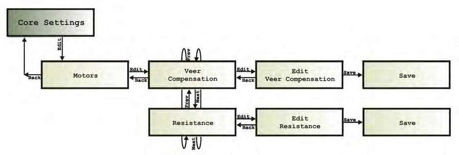
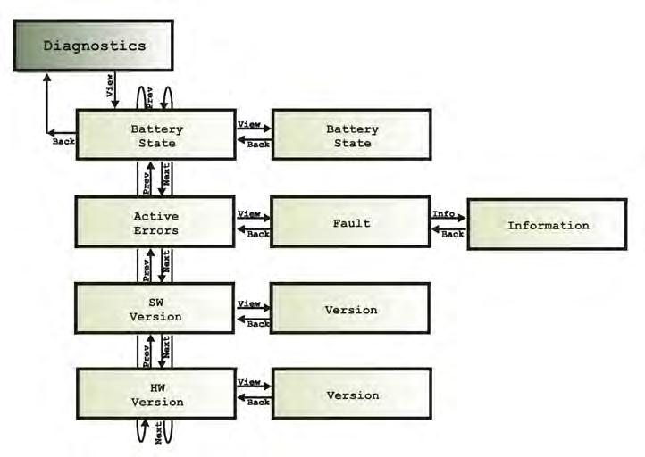
117 Inputs Core settings Diagnostics Programming - Page 115
118 Page 116 GBK54030 LiNX LE System User Manual Issue 6
119 9 Testing procedure 9.1 Before testing Testing procedure 117 Perform the testing procedure to make sure that the wheelchair meets a minimum level of safety. Warning: Do not connect the Battery Positive (B+) terminal of the battery to the LiNX LE System until the wheelchair is lifted off the ground. To prevent the risk of injury, Dynamic Controls recommends the use of a lifting device when lifting the wheelchair off the ground. 9.1 Before testing Check that all cables are connected correctly. Check especially that the polarities of the batteries, the motors and the park brakes are connected correctly and that the polarities are not swapped. To make sure that the wheelchair does not suddenly start to drive away when you turn it on, put blocks under the frame to lift the wheels off the ground. Check that the wheels can turn freely. Make the final connection to the Battery Positive (B+) terminal and close the circuit breakers. Turn on the LiNX LE System with the Power button on the Remote and program the LiNX LE System for the appropriate wheelchair application. Turn off the LiNX LE System with the Power button. 9.2 Testing procedure 1. Turn on the LiNX LE System with the Power button. Make sure that the controller turns on correctly. Check that all battery gauge LEDs turn on one by one and that, after the LiNX LE System has started up successfully, the battery gauge indicates the charge of the battery. 2. Press the Power button again to turn the LiNX LE System off. Check that it turns off correctly. Press the Power button again to turn the controller on again. 3. Press the Horn button. Check that the horn operates correctly. 4. Turn the LiNX LE System ON and OFF several times and listen. Check that the park brakes do not click. Leave the LiNX LE System ON. 5. Try to turn each drive wheel by hand to check that the park brakes are applied. It must not be possible to turn the wheels. 6. Push the joystick slightly out of the centre position. Check that the park brakes disengage (they will click when they disengage). 7. Move the joystick in all directions. Check that the wheels move smoothly in the correct direction. 8. Release the joystick back into the centre position. Check that the park brakes engage again (they will click when they engage). 9. Turn off the LiNX LE System and remove the blocks from under the chair. Testing procedure - Page 117
120 Warning: Perform the following procedure in a large open environment, preferably outdoors. Make sure that the wheelchair cannot crash into objects. Be prepared for unexpected chair movement in the event of a faulty installation. If the chair becomes uncontrollable, turn the LiNX LE System off for an emergency stop. 10. Turn on the LiNX LE System. Select the slowest speed with the Speed Dial. 11. Sit in the wheelchair and drive it SLOWLY (small joystick deflection) in all directions. Check for precise, smooth and progressive control. 12. Drive the chair QUICKLY (large joystick deflection) in all directions. Check for smooth and progressive control. 13. Select the highest speed with the Speed Dial and repeat steps 11 and Drive the chair at full speed, FORWARD. Check that the chair drives forward in a straight line (the chair does not veer to the left or to the right). 15. Drive the chair at full speed in REVERSE and check that the chair drives backwards in a straight line. Warning: Rear wheel drive chairs often are unstable in reverse, which can cause the chair to drive in circles even when the joystick is central, reverse. 16. Drive at full speed, FORWARD, and move the joystick from left to right along the front edge of the joystick restrictor plate, to check that you can still steer the chair. 17. Drive at full speed, FORWARD, and then release the joystick to the centre. Check that the chair decelerates smoothly and in a straight line. Check that the park brakes switch on when the chair stops. 18. Drive at full speed in REVERSE, and then release the joystick into the centre. Check that the chair decelerates smoothly and in a straight line. Check that the park brakes switch on when the chair stops. 19. Drive at full speed, FORWARD, and move the joystick into full reverse. Check that the chair decelerates smoothly and in a straight line before it moves in reverse. 20. Drive full speed in REVERSE, and move the joystick into the straight, forward position. Check that the chair decelerates smoothly and in a straight line before it moves in a forward direction. Note: Deceleration in reverse is slower. 21. Drive forward SLOWLY and switch the LiNX LE System OFF. Check that the chair stops quickly. 22. Push the joystick a little bit forward, and switch the LiNX LE System ON. Check that the chair does not drive and OONAPU is indicated. Release the joystick to the centre. Check that the chair drives normally. 23. Move the joystick forward just enough to release the park brake and check the creep speed. Repeat in reverse. 24. Drive the wheelchair up a 1 : 6 ramp. Check for normal power, smoothness and parking. 25. Reverse down the ramp and release the joystick when you are still on the ramp. Check that there is no rollback and that the park brakes switch on. 26. Accelerate up the ramp again, and reverse down the ramp to test for good control. 27. Repeat testing and programming of the LiNX LE System until the performance of the chair is as expected. 28. Park the chair in a safe location and turn off the LiNX LE System controller. Page Testing procedure


121 10 Diagnostics 10.1 The LiNX Access ios tool The LiNX Access PC tool Error indication The LiNX Access ios tool To view diagnostic information using an ios device, from the main screen tap on Logs and then select Active Errors, Event Log, or Real Time Diagnostics. Figure 123: LiNX Access ios diagnostics The Active Errors screen shows which errors, if any, are current. Each entry in this log displays the error, its flash code (e.g. FC5), and the component where the error is. Tap on the error entry to read more helpful information about the error. Figure 125: Active Errors screen Figure 124: Selecting Active Errors The Event Logs screen displays a historical view of all previous errors. Again, each entry in this log displays the error, its flash code (e.g. FC5), and the component where the error occurred. Tap on the error entry to read more helpful information about the error. Diagnostics - Page 119
 Battery Voltage (V) Speed Dial (%) Figure 126: Diagnostics screen 10.")
122 The Diagnostics screen presents the following graphs and data: Speed Demand (%) Turn Demand (%) Left Motor o Voltage (V) o Current (A) o Resistance (mω) Right Motor o Voltage (V) o Current (A) o Resistance (mω) Battery Voltage (V) Speed Dial (%) Figure 126: Diagnostics screen 10.2 The LiNX Access PC tool To view diagnostic information with the PC tool, click on the Logs tab to view current and historical system events. For all events, the following is recorded: event name, module, event code, time stamp. Figure 127: LiNX Access PC diagnostics Figure 128: Active errors and fault logs on the LiNX Access PC To view more information about the error, click on the error, and a helpful description will be displayed in the right-hand panel. Page Diagnostics

123 10.3 Error indication If there is an error with the system when it is powered up, then the status indicator will flash red; the number of flashes will indicate the type of error. Figure 129: The status indicator The table below describes the error indication, and a few possible actions that can be taken to rectify the problem. The actions listed are not in any particular order and are suggestions only; the intention is that one of the suggestions may help you clear the problem. If in doubt, consult your supplier. Flash code Error description Possible action 1 Remote / joystick error Check cables and connectors Replace Remote 2 Network or configuration error Check cables and connectors Check Bluetooth pairing Reconfigure the system Recharge the battery Check charger Replace modules Contact supplier 3 Left motor error Check cables and connectors Replace Power Module Check and/or replace left motor 4 Right motor error Check cables and connectors Replace Power Module Check and/or replace right motor 5 Left park brake error Check cables and connectors Check left park brake is released 6 Right park brake error Check cables and connectors Check right park brake is released 7 Module error (other than Remote) Check cables and connectors Check modules Replace LiNX Access Key Replace Power Module Recharge battery If the chair stalled, reverse away or remove obstacles, or if the chair was moved while turned off, cycle the power. The error indicator may continue to flash after an error has been rectified. To clear the error indication, cycle the system's power. For more information about the error, and what to do about it, open the logs within one of the programming & diagnostic tools (see 10.1 The LiNX Access ios tool and 10.2 The LiNX Access PC tool). Diagnostics - Page 121
124 Page 122 GBK54030 LiNX LE System User Manual Issue 6
125 11 Appendices 11.1 Accessories & parts list Systems Programming Connectors Miscellaneous Intended use and regulatory statement Intended use Device classification Compliance and conformance with standards LiNX Access Key Service life Maintenance Warranty Safety & misuse warnings Warnings to be included in the user manual Service and configuration warnings Electromagnetic compatibility Minimising emissions Environmental statement Symbols and labelling Product label - power modules Product label - Remote modules Product label - LiNX Access Keys Hardware and application firmware version label Tamper evident seal Other symbols and labels found on LiNX modules Serial number and date of manufacture Accessories & parts list The LiNX LE System is available to order under the following system part numbers: Systems Description Part number Modules included LiNX LE System with REM050 Remote, 40 A Power Module and 1 m Communications Bus cable LiNX LE System with REM050 Remote, 40 A Power Module and 1.5 m Communications Bus cable DLX DLX LiNX LE System with REM050 Remote, 40 A Power Module, 1 DLX m Communications Bus cable, and 0.9 m extension cable LiNX LE System with REM050 Remote, 40 A Power Module, 1 DLX m Communications Bus cable, and 0.64 m extension cable DLX-REM050-A DLX-PM40-A GLM-BUS100-A DLX-REM050-A DLX-PM40-A GLM-BUS150-A DLX-REM050-A DLX-PM40-A GLM-BUS100-A GLM-EXT090-A DLX-REM050-A DLX-PM40-A GLM-BUS100-A GLM-EXT064-A Appendices - Page 123
126 LiNX LE System with REM050 Remote, 50 A Power Module, and 1 m Communications Bus cable LiNX LE System with REM050 Remote, 50 A Power Module, and 1.5 m Communications Bus cable LiNX LE System with REM060 Remote, 40 A Power Module, and 1 m Communications Bus cable LiNX LE System with REM060 Remote, 40 A Power Module, and 1 m Communications Bus cable LiNX LE System with REM060 Remote, 50 A Power Module, and 1 m Communications Bus cable LiNX LE System with REM060 Remote, 50 A Power Module, and 1.5 m Communications Bus cable DLX DLX DLX DLX DLX DLX DLX-REM050-A DLX-PM50-A GLM-BUS100-A DLX-REM050-A DLX-PM50-A GLM-BUS150-A DLX-REM060-A DLX-PM40-A GLM-BUS100-A DLX-REM060-A DLX-PM40-A GLM-BUS150-A DLX-REM060-A DLX-PM50-A GLM-BUS100-A DLX-REM060-A DLX-PM50-A GLM-BUS150-A Programming Description Part number Qty/Unit LiNX Access Key ( version) DLX-HKEY01-A 1 LiNX Access Key ( version) DLX-HKEY02-A Connectors Description Part number Qty/Unit Connector kit DX INNERGY CON FEM AMP U DX POSITRON CONTACT FMALE SML DX-PM MOTOR CON HOUSING V3 DX-PM CONNECTOR KEY DX2 BATT/MOTOR CONN BOOT DK-PM Batt spade recpt 6-10mm DX2-PM Battery Conn Housing Miscellaneous DX2LOOM-PM1 GCN0781 GCN0794 GCN60325 GCN60323 GCN65129 GCN8002 GME65146 Description Part number Qty/Unit Extension Loom Panel Mounting Clip GME LiNX REM Mounting Adapter GME Intended use and regulatory statement Intended use The LiNX LE System is a microprocessor based system, intended for drive control of powered wheelchairs. The LiNX LE System typically comprises a Power Module and an interconnected user Remote. Page Appendices
127 The LiNX LE System is intended to drive powered wheelchairs fitted with 24 V motors with integrated park brakes Device classification Europe The LiNX LE System is a component of a Class I medical device as detailed in the Council Directive 93/42/EEC concerning Medical Devices. USA The LiNX LE System is a component of a Class II medical device (Powered Wheelchair) as detailed in 21 CFR Compliance and conformance with standards The LiNX LE System has been designed such that the combination of the wheelchair and controller, along with accessories as applicable, complies with the Essential Requirements of EU Directive 93/42/EEC (and amendments) by adopting relevant clauses of harmonised standards EN12184 and EN12182, and relevant parts of the FDA Recognized Consensus standard ANSI / RESNA WC-2 for performance LiNX Access Key The LiNX DLX-HKEYxx-A is a physical adaptor for use with the LiNX Remote family. It is used in conjunction with the LiNX Programming & Diagnostic Tools and is intended to allow the configuration, programming or diagnosis of LiNX wheelchair or scooter controller systems. Access level is controlled by the variant used (indicated by the value of 'xx'). The intended environment is indoors or outdoors in dry conditions Service life If the product has not been abused and all maintenance instructions as described in the maintenance section have been properly followed, the expected service life (i.e. minimum serviceable life expectancy) of the product is five (5) years. After this period, product reliability can no longer be guaranteed and Dynamic Controls recommends the product be replaced for safety reasons. Dynamic Controls accepts no responsibility/liability for product failure if the product is continued to be used after the expected service life period has expired. It is the 's responsibility to state the expected service life, as well as the inspection and maintenance schedules for all cables including the LiNX Communications Bus loom Maintenance The following instructions must be passed on to the operator before use of the product: Keep all Dynamic Controls electronic components free of dust, dirt and liquids. To clean the product, use a cloth dampened with warm soapy water. Do not use chemicals, solvents or abrasive cleaners, as this may cause damage to the product. Once a month, check all vehicle components for loose, damaged or corroded components, such as connectors, terminals or cables. Ensure that all connectors are fully mated. Restrain all cables to protect them from damage. Replace damaged components. Check for and remove any foreign objects or material. Appendices - Page 125
128 Every 6 months, test all switchable functions on the Dynamic Controls electronics system to ensure they function correctly. There are no user-serviceable parts in any Dynamic Controls electronic component. Do not attempt to open any case or undertake any repairs, else warranty will be voided and the safety of the system may be compromised. Where any doubt exists, consult your nearest service centre or agent. Warning: It is the responsibility of the end user to maintain the unit in a state of good repair at all times. If any component is damaged in any way, or if internal damage may have occurred (for example by being dropped), have it checked by qualified personnel before operating Warranty All equipment supplied by Dynamic Controls is warranted by the company to be free from faulty workmanship or materials. If any defect is found within the warranty period, the company will repair or, at its discretion, replace the equipment without charge for materials or labour. This warranty is subject to the provisions that the equipment: has been correctly installed. has been thoroughly checked upon completion of installation, and all programmable options correctly adjusted for safe operation prior to use. has been used solely in accordance with this manual and all other manuals of the Dynamic Controls electronic components that are used on the wheelchair. has been properly connected to a suitable power supply in accordance with this manual. has not been subjected to misuse or accident, or been modified or repaired by any unauthorised personnel. has been used solely for the driving of electrically powered mobility wheelchairs in accordance with the intended use and the recommendations of the wheelchair manufacturer. has not been connected to third party devices without the specific approval of Dynamic Controls Safety & misuse warnings Warnings to be included in the user manual The following warnings are applicable to the installer and must be passed on to the end user before use of the product. Do not install, maintain, or operate this equipment before you have read and understood all the instructions and all the manuals for this product and all the other products that you use or install together with this product. Follow the instructions of the manuals. If you do not follow all instructions, injury or damage can be the result. Do not try to open or disassemble any case there are no user-serviceable parts inside. The operator has the responsibility to keep the vehicle in a good safe operating condition. To protect all the components (for example the cables) from damage, the operator must fasten them in optimum positions. Do not touch the connector pins. If you touch the pins, they can become dirty or they can be damaged by electrostatic discharge. Immediately turn the controller off and consult your service agent if the vehicle: o Is damaged o Does not behave the same every time Page Appendices
129 o Does not respond normally, the way you expect it to o Becomes hotter than normal o Smokes o Arcs o Does not change its speed when you adjust the speed dial o Displays a fault on its fault indicator and the controller does not perform normally. Turn the controller off: o When you do not use it o Before you get in or get out of the vehicle o Before you use a mobile phone or a portable communications device near the vehicle o If your vehicle drives by itself or against your will. When you turn the controller off the vehicle will halt. In the case of an emergency while the vehicle is driving, press the On/Off button to perform an emergency stop and turn the controller off. If there is a risk of collision with a person or object in close proximity, use the Joystick and/or speed dial to reduce the speed of the wheelchair. Do not drive the vehicle if the controller indicates that the battery is low, since the wheelchair may stop operating and the user may become stranded. If the battery becomes completely empty, the vehicle will stop suddenly and the battery may be damaged. Make sure that the battery charger that is used with the vehicle has a drive inhibit function that is correctly connected for use with the controller. If you are not sure, ask your dealer or vehicle manufacturer. Specify the maximum current of any battery chargers to be used with the controller and warn against using battery chargers of higher current ratings. If operators of the vehicle are left with limited or no mobility for any reason (for example, because the vehicle loses electric power or breaks down), it is important that they can still call for assistance from wherever they may be. Go downhill slowly. When the vehicle drives downhill, the motors act as a dynamo and generate energy. The controller sends the generated energy from the motor to the battery. This charges the battery. However, if the battery is fully charged, it cannot accept the generated energy any more. When this happens, there is a risk of damage to the battery or an explosion. To prevent this risk, the controller forces the vehicle to slow down until the battery can accept more energy. After this, it allows the vehicle to speed up again. The result of this will be sudden speed changes of the vehicle. To prevent these speed changes with fully charged batteries, decrease the speed of the vehicle when going downhill. The controller can cause the vehicle to come to a sudden stop. If this can be dangerous to the operator, the installer must install a seat belt, and the operator must wear this seat belt. Operation of a vehicle on steep slopes can be dangerous. Before you drive up or down a slope, make sure that the slope does not exceed the capability of the vehicle. Do not use the park brake release on a slope. Make sure that the controller does not become colder or hotter than the minimum and maximum temperatures specified in this manual. Most electronic equipment is influenced by Radio Frequency Interference (RFI). Be careful when portable communications equipment is used in the area around such equipment. Dynamic Controls has made every effort to make sure that RFI does not change the behaviour of the controller, but very strong signals could still cause a problem. The vehicle manufacturer has the responsibility to make sure that the vehicle is tested according to local EMC regulations. Performance adjustments must only be made by healthcare professionals, or by persons who completely understand the programming parameters, the adjustment process, the Appendices - Page 127
130 configuration of the vehicle, and the capabilities of the driver. Wrong settings can make the vehicle uncontrollable or unstable. An uncontrollable or unstable vehicle can cause an unsafe situation such as a crash, with the risk of serious injury to the driver or bystanders, or damage to the vehicle or surrounding property. Performance adjustments must only be made indoors or outdoors in dry conditions. If the wheelchair has not been fitted with a hand guard for the Remote, the user should be made aware that their hand will not be protected from crushing, when, for example, manoeuvring towards a table. Users should be aware that the surface of the Remote can potentially get hot when exposed to strong sunlight for long periods. The XLR connector on the Remote is to be used exclusively for the intended purpose. Warranty will be voided if any unauthorised device is connected to this port. Depending on the installation, controls may be intended for the wheelchair occupant, attendant, or both. The manufacturer must state the intended user Service and configuration warnings The following warnings are applicable to the installation technician and the dealer or the therapist who supplies the vehicle to the end user. It is the responsibility of the installer to make sure that accessories that are connected to the wires of the vehicle do not interfere with the operation of the controller. Do not use the vehicle frame as the earth return. Any electrical low-resistance connection to the frame is a safety risk and is not allowed by international safety standards. If the vehicle loses electric power, it is important that an attendant is able to move the vehicle easily. After you have completed the installation, check it thoroughly. Correctly adjust all programmable options before the vehicle is used. After you have configured the vehicle, check to make sure that the vehicle performs to the specifications entered in the programming procedure. If the vehicle does not perform to specifications, reprogram it. Repeat this procedure until the vehicle performs to specifications. If the desired operation cannot be reached, contact your service agent. The dealer, therapist or other agent who supplies the vehicle to the end user has the responsibility to make sure that the vehicle is correctly configured for the needs of that user. For each individual user, the vehicle set up and configuration should take into consideration his or her: o technical knowledge, experience and education, and o medical and physical condition, including the level of disability and capability (where applicable). It is the responsibility of the and installer to make sure that the maximum driving speed of the vehicle is limited as appropriate when the vehicle is in a mechanically unstable position, for example when the seat is raised. It is the responsibility of the therapist/installer to minimise any risk of use error, including those arising from ergonomic features and/or the environment in which the device is intended to be used. Prior to handing over the vehicle, make sure that users are fully able to operate the product by giving them appropriate training on functionality and safety features, and having them testdrive the vehicle in a safe area in the presence of their agent. The controller can cause the vehicle to come to a sudden stop. If this can be dangerous to the operator, the installer must install a seat belt and the operator must wear this belt. Page Appendices
 transmitter. Before entering an RF-sensitive environment (e.g. a hospital), unplug the LiNX Access Key from the Remote.")
131 Where any inconsistencies about chair status occur between the LiNX LE System and that reported by a programming tool, the user should take the status as reported by the LiNX LE System as correct. A LiNX Access Key is an intentional radio frequency (RF) transmitter. Before entering an RF-sensitive environment (e.g. a hospital), unplug the LiNX Access Key from the Remote. Do not plug in the LiNX Access Key when in an RF-sensitive environment Electromagnetic compatibility Dynamic Controls Electronic Controllers have been tested on typical, representative vehicles to confirm compliance with the following appropriate EMC standards: USA: ANSI/RESNA WC-2:2009 Sec 21 Europe: EN12184:2009, ISO :2009 National and international directives require confirmation of compliance on particular vehicles. Since EMC is dependent on a particular installation, each variation must be tested. The guidelines in this section are written to assist with meeting EMC requirements in general Minimising emissions To minimise emissions and to maximise the immunity to radiated fields and ESD, follow the General Wiring Recommendations in section 6 of this manual Environmental statement Dynamic Controls confirms that the product variants specified in this manual, as sub-assemblies of electronic and electrical equipment supplied for further integration by a medical device manufacturer, conform to applicable requirements of Directive 2011/65/EU, recast of Directive 2002/95/EC - Restriction of the use of certain Hazardous Substances in electrical and electronic equipment. This product has been supplied from an environmentally aware manufacturer. Please be environmentally responsible and recycle this product at the end of its life through your local recycling facility. This product may contain substances that could be harmful to the environment if disposed of into a landfill. Do not dispose of this product in fire. See also: Appendices - Page 129


132 11.9 Symbols and labelling The following sections highlight the symbols and labels that can be found on the LiNX modules Product label - power modules This label can be found on the underside of the Power Module. Figure 130: Product label - Power Module Key: 1. WEEE symbol 2. Warning "Read Installation Manual before use" 3. Part description 4. Part number 5. Dynamic Controls logo 6. Dynamic Controls website 7. The module's IP rating 8. Serial number Product label - Remote modules This label can be found on the underside of the Remotes. Figure 131: Product label - Remote modules Key: 1. Part number 2. Dynamic Controls logo 3. Part description 4. Dynamic Controls website 5. Serial number Page Appendices


133 Product label - LiNX Access Keys This label can be found on the underside of the LiNX Access Key. Figure 132: Product label - LiNX Access Key Key: 1. Dynamic Controls website 2. Dynamic Controls logo 3. Part number 4. Warning "Read instruction manual before use" 5. WEEE symbol 6. Contains FCC ID 7. Serial number 8. Bluetooth Hardware and application firmware version label This label can be found on the underside of a module. Figure 133: Hardware and application firmware version label Key: 1. Hardware version 2. Hardware major version 3. Hardware minor version 4. Application version 5. Application major version 6. Application minor version Tamper evident seal This label can be found on the underside of a module. Figure 134: Tamper evident seal Appendices - Page 131
.")

 - indicates the direction for increasing/decreasing speed. The horn button (REM050).")


134 Other symbols and labels found on LiNX modules IPx4 This is the enclosure's ingress protection rating. This is the WEEE symbol (Waste Electrical and Electronic Equipment Directive). The petrol pump indicates the battery charger input (on REM060). Warning to read the instruction manual before using the module. Read instruction manual before use Speed control (REM050) - indicates the direction for increasing/decreasing speed. Speed control (REM060) - indicates the direction for increasing/decreasing speed. The horn button (REM050). The horn button (REM060). Power button / emergency stop Serial number and date of manufacture The serial number on a LiNX product provides both the date of manufacture as well as a unique serial number for the particular module. Figure 135: Serial number example The format, as shown in Figure 135, is MYYnnnnnn, where: M is the month of manufacture, using the letters A to L (A = Jan, B = Feb, C = Mar, etc.), YY is the year of manufacture, nnnnnn is a unique 6 digit sequential number. For example, the module's serial number, as shown in Figure 135, begins with A14 indicating that it was manufactured in January 2014, and its unique, sequential value is Page Appendices
135 12 Index A Anti-Rollaway 59 Anti-Rollaway (no battery) max speed 59, 66 Anti-rollaway holding current 59, 66 Anti-Rollaway max speed 59, 65 B B , 39 B , 39 Base Plate 36 Batt Gauge Dead Zone 60, 76 Batt Gauge High Voltage Warning 60, 77 Batt Gauge Low Voltage Warning 60, 77 Batt Gauge Maximum 60, 77 Batt Gauge Minimum 60, 77 Battery Charging 50 Battery Connector Battery Gauge 44, 48 Battery Negative 29-30, 39 Battery Positive 29-30, 39, 117 Battery Status 44 Boost Current 59, 71 Boost Time 59, 71 C Cable Bend Radius 22 Capacitor 24 Charging Current Circuit Breaker 31, 117 Class I Medical Device 125 Class II Medical Device 125 Communications Bus 22, Communications Bus High 30, 39 Communications Bus Low 30, 39 Compatible Battery Supply Compatible Motor Compatible Park Brake Connector Latch Holding Force 22 Connector Pin-outs 29 Core Settings - Battery Management 75 Core Settings - General 62 Core Settings - Motors 67 Core Settings - Park Brake 74 Current Limit 59, 71 Current Rating Cut-Off Voltage 49, 60, 78 D Device Classification 125 Drive Delay At Startup 58, 62 Drive Inhibit 39, 45 Drive Settings - Forward 79 Drive Settings - Reverse 86 Drive Settings - Stability 95 Drive Settings - Turn 90 Dual Park Brake Test 59, 74 E Electromagnetic Compatibility (EMC) 24, 129 Emergency Deceleration 45, 58, 62 Emergency Stop 45 Enable Joystick Wakeup 58, 65 Enable Lock 58 Enable Sleep Timeout 58 Environment 129 ESD 24 F Fault Indicator 49, 121 Female Connectors 26 FET Thermal Rollback 72 FET Thermal Rollback End 59, 72 FET Thermal Rollback Start 59, 72 Firmware Upgrade 58, 63, 103 Flex Radii 41 Forward Acceleration 60, 80, 83 Forward Deceleration 60, 80, 83 Forward Speed 60 Forward Speed Scalar 60, 80 G Gel Cell 30 H High Batt Rollback End 60, 76 High Batt Rollback Start 60, 76 High Batt Rollback Start/End 76 High voltage warning 48 Horn 46 Horn Button 46 I Idle current 20 Inputs 101 Installation Procedure 23 Index - Page 133
136 J Joystick 46 Joystick Throw 61, 101 L Lead-Acid 20-21, 30 LED 117 Left Invert 59, 69 Load Compensation 14, 67 Lock 58 Lock Function 47 Loom Resistance 22 Low Batt Rollback End 60, 75 Low Batt Rollback Start 60, 75 Low Batt Rollback Start/End 75 Low Voltage Warning 49 M Maintenance 125 Manual Park Brake Release Switch 34 Max Forward Speed 60, 79, 82 Max No Load Voltage 59, 70 Max Reverse Speed 60-61, 86, 88 Max Speed in Turn 61, 100 Max Turn Speed 61, 90, 93 Maximum Cable Strain 22 Mechanical Park Brake Release 35 Min Forward Speed 60, 82 Min Forward/Reverse Speed 60, 79 Min Reverse Speed 61, 89 Min Turn Speed 61, 90, 93 Motor A 30 Motor B 30 Motor Connections 32 Motor Connector 30 Motor Inversion 108 Motor Output Motor Resistance 59, Motor Resistance Profile 59, 69 Motor Swap 108 Mounting 26, 36 Mounting Orientation 26 N Neutral Window 61, 101 O Forward Acceleration 60, 81 Forward Deceleration 60, 82 Forward Speed 60, 81 Reverse Acceleration 60, 87 Reverse Deceleration 61, 88 Reverse Speed 60, 87 Turn Acceleration 61, 92 Turn Deceleration 61, 92 Turn Speed 61, 91 Turn Transition 61, 99 OONAPU 45 Open Circuit Test 59, 73 Operating Forces Operating Humidity Range Operating Temperature 22 Operating Temperature Range Operating Voltage Operating Voltage Range 20 P 106 Park Brake Negative 30 Park Brake Output Park Brake Positive 30 Park Brakes 33, 117 Park Brakes, 12V 34 Park Brakes, 24V 33 PB- 30 PB+ 30 Power Button 44, 117 Power Module 26 Power OFF 44, 47 Power ON 44, 47 Program First Written 58, 64 Program Last Modified 58, 64 Program Name 58, 63 Programmer Identifier 58, 64 Protection Rating Q Quiescent current 20 Quiescent Current (Idle) 21 Quiescent Current (Power Off) R Ramp 118 Recycle 129 Release Delay 59, 74 Remote 36, 43, 117 Remote Dimensions Page Index
137 Reverse Acceleration 60-61, 86, 89 Reverse Deceleration 60-61, 86, 89 Reverse Speed 60 Reverse Supply Voltage Right Invert 59, 69 S Safety & Misuse Warnings 126 Service and Configuration Warnings 128 Service Life 125 Shipping Weight Short Circuit Test 59, 73 Sleep Timeout 58 Sleep Timeout Duration 58, 65 Soft Finish Acceleration 60, 84 Soft Finish Deceleration 60, 85 Soft Finish Turn 61, 94 Soft Start Acceleration 60, 84 Soft Start Deceleration 60, 85 Soft Start Turn 61, 94 Soft Start/Finish Acceleration 84 Soft Start/Finish Deceleration 85 Speed Dial 46, 118 Speed Symbol 46 Stability At Max Speed Dial 61, 97 Stability At Min Speed Dial 61, 96 Stall Timeout 58, 63 Status Indicator 44, 49 Storage Temperature Range Suppression Device 34 Swap 59, 70 System Name 58, 63 V Veer Compensation 59, 67 W Warranty 126 X XLR Charger Connector 39 T Thermal Rollback 72 Thermal Rollback End 59, 72 Thermal Rollback Start 59, 72 Tremor dampening 61, 102 Turn Acceleration 61, 90, 93 Turn at Max Speed 61, 100 Turn At Max Speed 61, 95 Turn Boost At Max Speed 61, 91 Turn Deceleration 61, 90, 93 Turn Response 61, 95 Turn Speed 61 Turn Transition 61, 100 U UL Index - Page 135
: +886-955-335 243 Ph: (China): +86-512-6289 2847 Fax: +886-2-2598 1562 asiasales@dynamiccontrols.com Ph: +64-3-962-2519 Fax: +64-3-962-2966 sales@dynamiccontrols.")
138 EUROPE ASIA AUSTRALASIA CORPORATE OFFICE USA Ph: Fax: Ph: (Taiwan): Ph: (China): Fax: Ph: Fax: Ph: Fax: Dynamic Controls is the world s leading manufacturer of electronic controls for power wheelchairs and scooters. Dynamic Controls was established in 1972 and is headquartered in New Zealand. Regional centres are located in Europe, United States, Asia, and Australasia. ISO certified Dynamic Controls goes above and beyond industry standard expectations to ensure customers receive the best products possible.
DS90, DS120 and DS160 DS90-ACT, DS120-ACT and DS160-ACT Scooter Controllers
 RHINO2 DS90, DS120 and DS160 DS90-ACT, DS120-ACT and DS160-ACT Scooter Controllers Installation Manual Rhino2 Installation Manual Issue 2.0, October 2011 GBK51948 About this Manual This manual can help
R-series DR50 and DR90 Scooter Controllers
 R-series DR50 and DR90 Scooter Controllers Installation Manual GBK52040 Issue 9, June 2016 About this Manual This manual can help you understand and install the Dynamic Controls (DYNAMIC) R-SERIES scooter
MyLiNX Application Quick Start Guide for Android
 MyLiNX Application Quick Start Guide for Android MyLiNX Application Quick Start Guide for Android GBK54155 Issue 1 Page left blank intentionally GBK54155 MyLiNX Application Welcome Welcome to the MyLiNX
DO Driving Simplicity
 DO Driving Simplicity LiNX [lingks] noun, linx for 1. a relationship or CONNECTION between people, or organisations that enables communication. a key connection from clients to their world, providers to
DX Environmental Control Unit
 DX Environmental Control Unit Important Notes: (Part No. DX-ECU) Installation Manual GBK64227 issue 4 September 2004 1. Read this Manual carefully before installing or operating your DX control system.
WHERE, HOW, WHEN, WHAT, IF...
 WHERE, HOW, WHEN, WHT, IF... Frequently sked uestions Rehab Redefined with LiNX Technology MyLiNX System u MyLiNX System is a remote diagnostics and informatics solution for the Invacare TDX SP2 Power
Programming notes: This icon denotes that the paragraph refers to the programming of SHARK.
 GBK80257 Issue 3, September 2015 About this Manual This manual has been designed to help you install and configure a Dynamic Controls (Dynamic) SHARK powerchair control system for a generic brand powerchair.
Lester Electrical ChargerConnect App User s Guide
 Lester Electrical ChargerConnect App User s Guide Lester Electrical Summit Series II chargers features Bluetooth wireless communication, which can be accessed using an Apple or Android smart phone, tablet,
Technical Documentation
 Technical Documentation Product manual Holding brake controller Document: 0198441113316 Edition: V1.00, 03.2006 Important information The drive systems described here are products for general use that
power module THE ULTIMATE POWERCHAIR CONTROL SOLUTION INSTALLATION MANUAL
 power module THE ULTIMATE POWERCHAIR CONTROL SOLUTION DX2-PMA INSTALLATION MANUAL About this Manual This manual can help you understand and install the DYNAMIC DX2 PMA Power Module. It describes the general
Pro Booster 802Li. Please read and fully understand the instructions in this manual before operation. Keep this manual safe for future reference.
 Please dispose of packaging for the product in a responsible manner. It is suitable for recycling. Help to protect the environment, take the packaging to the local amenity tip and place into the appropriate
Installation Guide Smart-UPS On-Line SRT1000/1500 UXI-NCLI, SRT1000/1500 UXI-LI, Tower/Rack-Mount
 Installation Guide Smart-UPS On-Line SRT1000/1500 UXI-NCLI, SRT1000/1500 UXI-LI, Tower/Rack-Mount Important Safety Messages Read the instructions carefully to become familiar with the equipment before
Rescue Pac. Please read and fully understand the instructions in this manual before operation. Keep this manual safe for future reference
 Please dispose of Packaging for the product in a responsible manner. It is suitable for recycling. Help to protect the environment, take the packaging to the local amenity tip and place into the appropriate
User Manual. Solar Charge Controller 3KW
 User Manual Solar Charge Controller 3KW 1 CONTENTS 1 ABOUT THIS MANUAL... 3 1.1 Purpose... 3 1.2 Scope... 3 1.3 SAFETY INSTRUCTIONS... 3 2 INTRODUCTION... 4 2.1 Features... 4 2.2 Product Overview... 5
User Manual Solar Charge Controller 3KW
 User Manual Solar Charge Controller 3KW Version: 1.3 CONTENTS 1 ABOUT THIS MANUAL... 1 1.1 Purpose... 1 1.2 Scope... 1 1.3 SAFETY INSTRUCTIONS... 1 2 INTRODUCTION... 2 2.1 Features... 2 2.2 Product Overview...
POWER FOR TOMORROW. Motive Power. Network Power. Chargers. Bloc Batteries. Accessories. Service
 POWER FOR TOMORROW TODAY The Eternity Technologies range is built using only the highest quality and most efficient production processes at our state-of-the-art manufacturing centre in the UAE. It is this
Kelly HSR Series Motor Controller with Regen User s Manual V 3.3. Kelly HSR Opto-Isolated Series Motor Controller with Regen.
 Kelly HSR Opto-Isolated Series Motor Controller with Regen User s Manual HSR72601 HSR72801 HSR12401 HSR12601 HSR12901 HSR14301 HSR14501 HSR14701 Rev.3.3 Dec. 2011 Contents Chapter 1 Introduction... 2 1.1
Permanent Magnet Motor Speed Controller 1212S / 1212P / 1212C
 Motor Controllers Permanent Magnet Motor Speed Controller 1212S / 1212P / 1212C www.curtisinstruments.com 1 The Curtis Model 1212S, 1212P and 1212C Motor Speed Controllers provide efficient, optimal control
Switching DC Power Supply
 99 Washington Street Melrose, MA 02176 Phone 781-665-1400 Toll Free 1-800-517-8431 Visit us at www.testequipmentdepot.com Model 1693, 1694 Switching DC Power Supply INSTRUCTION MANUAL 1 Safety Summary
INSTALLATION INSTRUCTIONS
 INSTALLATION INSTRUCTIONS WARNING: WARNING: www.altronicinc.com DEVIATION DEVIATION FROM THESE FROM INSTRUCTIONS THESE INSTRUCTIONS MAY LEAD MAY TO LEAD IMPROPER TO IMPROPER OP- ERATION OF ENGINE THE MACHINE
High Frequency SineWave Guardian TM
 High Frequency SineWave Guardian TM 380V 480V INSTALLATION GUIDE FORM: SHF-IG-E REL. January 2018 REV. 002 2018 MTE Corporation High Voltage! Only a qualified electrician can carry out the electrical installation
VR2 TECHNICAL MANUAL SK77898/4
 VR2 TECHNICAL MANUAL SK77898/4 PG Drives Technology 2012 All rights reserved. This manual is furnished under copyright and may only be used in accordance with the terms laid out by PG Drives Technology.
User s Manual. Automatic Switch-Mode Battery Charger
 User s Manual Automatic Switch-Mode Battery Charger IMPORTANT Read, understand, and follow these safety rules and operating instructions before using this battery charger. Only authorized and trained service
Installation and Operating Instructions. MPPT Solar System Controller ISC3040
 Installation and Operating Instructions MPPT Solar System Controller ISC3040 ABOUT THIS MANUAL These operating instructions come with the product and should be kept with it as a reference to all user s
Installation and Operating Instructions. Solar System Controller ISC3030
 Installation and Operating Instructions Solar System Controller ISC3030 ABOUT THIS MANUAL These operating instructions come with the product and should be kept with it as a reference to all user s of the
Kelly HPM High Power Full Bridge Permanent Magnet DC Motor Controller User s Manual
 Kelly HPM High Power Full Bridge Permanent Magnet DC Motor Controller User s Manual HPM72601 HPM72801 HPM12401 HPM12601 HPM12801 HPM14301 HPM14501 HPM14701 Rev.3.4 Dec. 2016 Contents Chapter1 Introduction...
Installation and Operation Manual. LD LED Dimmer
 Installation and Operation Manual LD12-002 LED Dimmer SM85 ISSUE 1.00 Northern Airborne Technology Ltd. 1925 Kirschner Road Kelowna, BC, Canada. V1Y 4N7 Telephone (250) 763-2232 Facsimile (250) 762-3374
ST - II Series POWER SUPPLIES USER INSTRUCTIONS
 Introduction ST - II Series POWER SUPPLIES These instructions detail the installation and operation requirements for the ST20-II & ST35-II power supplies. These have been designed for operation in RV s
Devices Supported: KEB48220 KEB48221 KEB48300 KEB48301 KEB48400 KEB48401 KEB48600 KEB48601 KEB72330 EB KEB72450 KEB EB KEB72600 KEB
 Kelly KEB Brushless Motor Controller User s Manual Devices Supported: KEB48220 KEB48221 KEB48300 KEB48301 KEB48400 KEB48401 KEB48600 KEB48601 KEB72330 KEB EB72 72331 KEB72450 KEB EB72 72451 KEB72600 KEB
Automatic Battery Charger Switching mode with Micro-controlled Input: Vac / Output: 12Volt DC
 Automatic Battery Charger Switching mode with Micro-controlled Input:220-260Vac / Output: 12Volt DC User s Manual and Important Safety Information Model: OC-SW121080 / OC-SW121160 / OC-SW121210 FEATURES
CP-250E-60/72-208/240-MC4 Microinverter with Modular Trunk Cable
 CP-250E-60/72-208/240-MC4 Microinverter with Modular Trunk Cable Chilicon Power Aug 2016 1 CONTENTS CP-250E Microinverter System... 3 The CP-100 Cortex Gateway... 3 Important Safety Information... 4 Inverter
1x 20A H Bridge output for controlling direction of DC motors through polarity change (MOI)
") Product description: Output Interface (OI): The Output Interface module is where the circuit control and protection takes place, these modules have been designed to be mounted in many locations around
Product description: Output Interface (OI): The Output Interface module is where the circuit control and protection takes place, these modules have been designed to be mounted in many locations around
SG-B1 SERIES / SG-A1 SERIES
 643 Door with Solenoid Interlock / Door Ultra-slim SG-B1 SERIES / SG-A1 SERIES Related Information General terms and conditions... F-7 General precautions... P.1501 PHOTO PHOTO Conforming to Machine &
K25000 & KD25000 Series
 K25000 & KD25000 Series Fire Alarm Power Supplies Installation, Commissioning and Operating Manual Man-1128 Issue 14 January 2016 Man-1128_K25400_series_Power_Supply_Manual_14 Page 1 of 20 Section Page
BATTERY BOOSTER/CHARGER MODEL NO: DIGICAR 600
 BATTERY BOOSTER/CHARGER MODEL NO: DIGICAR 600 PART NO: 6261200 OPERATION & MAINTENANCE INSTRUCTIONS LS0815 INTRODUCTION Thank you for purchasing this CLARKE Battery booster / charger which is suitable
Rental Industry Safety Tester Safe Check 5s
 Rental Industry Safety Tester Safe Check 5s Feb 2006 2006 Clare Instruments Inc. Issue 2.0 Firmware Version : 1.2a Limited Warranty & Limitation of Liability Clare Instruments Inc, guarantees this product
Operating Manual
 Operating Manual 15-24-1000 15-36-1000 1. Safety 2 1.1 Warnings, Cautions and Notes 2 1.2 General Warning 2 1.3 Fire Risk 2 1.4 Electric Shock Risk 2 1.5 Chemical Risk 3 1.6 Do s 3 1.7 Do Not s 3 1.8 DC
SurePower Battery Pack Guide
 ? SurePower Battery Pack Guide 9650-0536-01 Rev. B The issue date for the SurePower Battery Pack Guide (9650-0536-01 Rev. B) is September, 2010. If more than three years have elapsed since the issue date,
Filtered PWM Speed Control for Permanent Magnet DC Motors
 Instructions for Installation and Operation Filtered PWM Speed Control for Permanent Magnet DC Motors Model 0794 Speed and Direction Control up to 5/8 HP NEMA-1/IP-20 Specifications Product Type:... WPM-2148E1
Automatic Battery Charger Switching mode with Micro-controlled Input: Vac / Output: 12Volt DC
 Automatic Battery Charger Switching mode with Micro-controlled Input:220-260Vac / Output: 12Volt DC User s Manual and Important Safety Information Model: OC-SW121080 / OC-SW121160 / OC-SW121210 FEATURES
Nature Power Inverters. True Sinewave Inverter Modified Sinewave Inverter. Owner s Manual
 Version 1.1 Version 2 Nature Power Inverters True Sinewave Inverter Modified Sinewave Inverter Owner s Manual!!!!!!!!!!! 38304 38204 For safe and optimum performance, the Power Inverter must be used properly.
Kelly KDHA High Voltage Series/PM Motor Controller User s Manual
 Kelly KDHA High Voltage Series/PM Motor Controller User s Manual KDH07500A KDH07501A KDH07700A KDH07701A KDH09400A KDH09401A KDH09500A KDH09501A KDH12400A KDH12401A KDH12500A KDH12501A KDH14300A KDH14301A
INSTALLATION MANUAL - v4
 I-LOCKTM COUPLER INSTALLATION MANUAL - v4 SPECIAL NOTE Your new Wedgelock Coupler fitted with the I-LOCK TM Safety Device requires the installation of a third hydraulic line - please follow the instructions
Quick Start Guide TK3/TK4 Thermal System Assembly and Fan Shroud Assembly
 Quick Start Guide TK3/TK4 Thermal System Assembly and Fan Shroud Assembly This Quick Start Manual is effective for Consumer installations of the part numbers listed in Table 1 and Table 2. OEM installers
BATTERY BOOSTER/CHARGER MODEL NO: DIGICAR 900
 BATTERY BOOSTER/CHARGER MODEL NO: DIGICAR 900 PART NO: 6261205 OPERATION & MAINTENANCE INSTRUCTIONS LS0715 INTRODUCTION Thank you for purchasing this CLARKE Battery booster / charger which is suitable
Full Bridge Permanent Magnet DC Motor Controller User's Manual
 www.igreatway.com Email:info@igreatway.com V 3.3 Full Bridge Permanent Magnet DC Motor Controller User's Manual PM24101 PM24201 PM24301 PM36101 PM36201 PM48101 PM48201 PM48301 PM48401B PM48501B PM72101
& HIGH CURRENT DC POWER SUPPLIES INSTRUCTION MANUAL
 72-6850 & 72-6852 HIGH CURRENT DC POWER SUPPLIES INSTRUCTION MANUAL Table of Contents Introduction 2 Specification 2 Safety 4 EMC 5 Installation 6 Connections 6 Operation 7 Maintenance and Repair 8 www.tenma.com
RVS-DX Digital Reduced Voltage Motor Starter
 RVS-DX Digital Reduced Voltage Motor Starter Specification Guide Specification Guide Contents 1.0 Introduction 2.0 Specifications 2.1 Standard Performance Features 2.2 Standard Protection Features 2.3
Tug Compact. Operating Manual
 Tug Compact Operating Manual Tug Compact Operating Manual OM0012E/2 This manual contains important safety, installation and operating instructions for this unit. Read this manual thoroughly and completely,
Orion BMS Purchasing Guide Rev. 1.2
 www.orionbms.com Orion BMS Purchasing Guide Rev. 1.2 Main Components... 2 Orion BMS Unit... 2 Current Sensor... 4 Thermistors... 5 CANdapter... 6 Wiring Harnesses... 7 Cell voltage tap wiring harnesses...
EPC DC MOTOR SPEED CONTROL
 EPC DC MOTOR SPEED CONTROL OPERATION AND INSTRUCTION MANUAL THIS MANUAL IS PUBLISHED BY EPC CORPORATION AND IS TO BE DISTRIBUTED ONLY WITH NEW EPC CONTROLS AND EQUIPMENT NO OTHER DISTRIBUTION IS PERMITED
PSU1 Power Supply Unit
 OM2443 PSU1 Power Supply Unit Distributed By: GMW Associates 955 Industrial Road, San Carlos, CA, 94070 USA PHONE: +1 650-802-8292 FAX: +1 650-802-8298 EMAIL: sales@gmw.com WEB: www.gmw.com Table of Contents
SI AT A22. English. Printed: Doc-Nr: PUB / / 000 / 03
 SI AT A22 English 1 Information about the documentation 1.1 About this documentation Read this documentation before initial operation or use. This is a prerequisite for safe, trouble-free handling and
STR3. Step Motor Drive. User Manual
 STR3 Step Motor Drive User Manual Contents 1 Introduction... 3 1.1 Overview... 3 1.2 Features... 3 1.3 Block Diagram... 4 1.4 Safety Instructions... 5 2 Getting Started... 6 2.1 Mounting Hardware... 6
MGE TM Galaxy TM 7000
 MGE TM Galaxy TM 7000 Power efficiency for business continuity 160/200/250/300/400/500 kva > Performance 3 Phase Power Protection with high adaptability to meet the unique requirements of Medium to Large
Document: PRODSPEC-140 Revision: G DCN No Date: October 1, 2014 Product: 10-amp EnerGenius NRG Battery Charger
 Document: PRODSPEC-140 Revision: G DCN No. 106512 Date: October 1, 2014 Product: 10-amp EnerGenius NRG Battery Charger 1. GENERAL DESCRIPTION 1.1 General Description Fully regulated, constant voltage,
Cover. L5v2 Plug-In Conversion Module(PCM) Diagnostic Trouble Codes
 Diagnostic Trouble Codes") Cover L5v2 Plug-In Conversion Module(PCM) Diagnostic Trouble Codes Copyright 2009 A123 Systems, Inc. All rights reserved DOCUMENT NOTICE: The information contained in this manual is the property of A123
Cover L5v2 Plug-In Conversion Module(PCM) Diagnostic Trouble Codes Copyright 2009 A123 Systems, Inc. All rights reserved DOCUMENT NOTICE: The information contained in this manual is the property of A123
PG DRIVES TECHNOLOGY VR2 - TECHNICAL MANUAL SK77898/5
 PG DRIVES TECHNOLOGY VR2 - TECHNICAL MANUAL SK77898/5 Curtiss-Wright 2014 All rights reserved. This manual is furnished under copyright and may only be used in accordance with the terms laid out by Curtiss-
Special Specification 6058 Battery Back-Up System for Signal Cabinets
 Special Specification Battery Back-Up System for Signal Cabinets 1. DESCRIPTION 2. DEFINITIONS Install a Battery Back-Up System (BBU System) for traffic signals that will provide reliable emergency power
EVS RP6020. Instruction Manual
 Instruction Manual TDK Lambda BEFORE USING THE PRODUCT Be sure to read this instruction manual thoroughly before using this product. Pay attention to all cautions and warnings before using this product.
ELECTRIC SCHEMATICS LS1 LS2. "1532ES / 1932ES" Service & Parts Manual - ANSI Specifications March 2008 Page 5-9 ART_2236 ART_2243
 ELECTRIC SCHEMATICS NOTES: (Unless otherwise specified). Switch S BASE/PLATFORM makes contact from the CENTER to the LEFT position when placed in BASE.. Switch S UP/DOWN makes contact from the CENTER to
27.6 Vdc 1 Amp Switch Mode Power Supply for Fire EN54-4:1997 +A1 +A2
 1 27.6 Vdc 1 Amp Switch Mode Power Supply for Fire EN54-4:1997 +A1 +A2 STX2401-C STX2401-T FEATURES 0843-CPR-0213 14 Elmdene International Ltd Tel: +44(0)23 9269 6638 3 Keel Close, Interchange Park, Fax:
80V 300Ah Lithium-ion Battery Pack Data Sheet
 80V 300Ah Lithium-ion Battery Pack Data Sheet 80 V, 300 amp-hour capacity, maintenance-free energy storage, IP65 design, fully integrated BMS, integrated fuse and safety relay protection, highly configurable
Operators and Maintenance Manual. Display EEM MOT 01 FE02.02
 1/16 Operators and Maintenance Manual Display EEM MOT 01 FE02.02 Rev. 01 December 2017 2/16 Table of Contents Introduction... 3 1. General information... 3 2. Handling in transport and storage... 4 3.
Installation Guide Smart-UPS On-Line SRT1000/SRT1500 XLA Tower/Rack-Mount
 Installation Guide Smart-UPS On-Line SRT1000/SRT1500 XLA Tower/Rack-Mount Important Safety Messages Read the instructions carefully to become familiar with the equipment before attempting to install, operate,
RP Instruction Manual
 Instruction Manual TDK Lambda BEFORE USING THE PRODUCT Be sure to read this instruction manual thoroughly before using this product. Pay attention to all cautions and warnings before using this product.
Generator Set Applications FT-10 Network Control Communications Module (CCM-G) Kit
 Kit") Instruction Sheet 10 2004 Generator Set Applications FT-10 Network Control Communications Module (CCM-G) Kit 541 0810 GENERAL INFORMATION This kit contains one Control Communications Module (CCM-G) with
Instruction Sheet 10 2004 Generator Set Applications FT-10 Network Control Communications Module (CCM-G) Kit 541 0810 GENERAL INFORMATION This kit contains one Control Communications Module (CCM-G) with
Small Full Bridge Permanent Magnet Motor DC Controller User Manual
 Small Full Bridge Permanent Magnet Motor DC Controller User Manual SPM24051X SPM24101X SPM24121X SPM48051X SPM48101X SPM48121X SPM72051X SPM72101X SPM72121X SPM48151E SPM48181E SPM48221E SPM72151E SPM72181E
Installation and Operating Instructions. Solar System Controller ISC3020
 Installation and Operating Instructions Solar System Controller ISC3020 ABOUT THIS MANUAL These operating instructions come with the product and should be kept with it as a reference to all user s of
SI AT A22. English. Printed: Doc-Nr: PUB / / 000 / 01
 SI AT A22 English 1 Information about the documentation 1.1 About this documentation Read this documentation before initial operation or use. This is a prerequisite for safe, trouble-free handling and
Digitrip Retrofit System for ITE K-3000, K-3000 S, K-4000 and K-4000 S Breakers
 Supersedes IL 33-858-4 Dated 05/02 Digitrip Retrofit System for ITE K-3000, K-3000 S, K-4000 and K-4000 S Breakers Digitrip Retrofit System for ITE K-3000, Digitrip Retrofit System for ITE K-3000, K-3000
Kelly KDC Series/PM Motor Controller User s Manual
 Kelly KDC Series/PM Motor Controller User s Manual KDC48600 KDC48601 KDC48602 KDC48603 KDC72600 KDC72601 KDC72602 KDC72603 KDC72800 KDC72801 KDC72802 KDC72803 KDC12602 KDC12603 Rev.3.3 May 2011 Contents
Compact Heat Meters. Features. -A Pulsed output. -B M-Bus output. Accessories. UK Sales Tel: International Tel:
 Compact Heat Meters Features Compact design Simple operation Pulsed output Measures heating or cooling Specification Product Codes Water Meter Temp. range 10 to 90 C Nominal pressure 16bar Installation
Datasheet PDCSY-MW-CHM. Technical Overview. Features. Product warranty and total quality commitment. General Information.
 Datasheet Compact Heat Meters Technical Overview Heat energy is calculated by using a matched pair of high accuracy sensors to measure the difference between the forward and flow temperatures. The amount
Owner s Manual for the Travelite Electric Wheelchair
 Tel: 083 284 2973 Fax:086 232 5223 Email:ruan@cheapest-wheelchairs.co.za OR rosslyn@adpwheelchairs.co.za Web: www.cheapest-wheelchairs.co.za ORwww.adpwheelchairs.co.za Owner s Manual for the Travelite
LIGHTNING PROTECTION UNIT (LPU)
") LIGHTNING PROTECTION UNIT (LPU) Photovoltaic Lightning Protection Device Installation and Operation Manual SPECIALTY CONCEPTS, INC. 8954 Mason Ave. Chatsworth, CA 91311 USA MODELS COVERED: LPU-50, LPU-150,
LIGHTNING PROTECTION UNIT (LPU) Photovoltaic Lightning Protection Device Installation and Operation Manual SPECIALTY CONCEPTS, INC. 8954 Mason Ave. Chatsworth, CA 91311 USA MODELS COVERED: LPU-50, LPU-150,
Smart Battery Charger
 BATTERY CHARGER Smart Battery Charger Model No. WSC-1215 (SB) WSC-1230 (SB) WSC-2408 WSC-2415 Manual Please read this manual carefully before installing and starting up this device. Figure 1 WSC-1215SB
INTRODUCTION. Specifications. Operating voltage range:
 INTRODUCTION INTRODUCTION Thank you for purchasing the EcoPower Electron 65 AC Charger. This product is a fast charger with a high performance microprocessor and specialized operating software. Please
KL-8070D. Fully Digital Stepping Driver. Table of Contents 1. Introduction, Features and Applications...1 Introduction...1 Features...
 Contents KL-8070D Fully Digital Stepping Driver Attention: Please read this manual carefully before using the driver! I Table of Contents 1. Introduction, Features and Applications...1 Introduction......1
Safety and Installation Instructions For Fluitecnik PV Modules
 Safety and Installation Instructions For Fluitecnik PV Modules 1.0 Introduction This manual provides safety and installation instructions for (PV) Fluitecnik Sun Energy photovoltaic (PV) modules registered
T H E U L T I M A T E L A S E R D E F E N S E S Y S T E M
 S P E E D O F L I G H T P R O T E C T I O N CINCINNATI MICROWAVE 5440 West Chester Road West Chester OH 45069 Sales/Service 800-433-3487 EscortRadar.com 2014 CINCINNATI MICROWAVE. ESCORT, Laser ShifterPro,
SurePower TM II Battery Pack Guide
 TM SurePower TM II Battery Pack Guide? 1:00+ 2:00+ 3:00+ TM 9650-000840-01 Rev. B The issue date for the SurePower II Battery Pack Guide (REF 9650-000840-01 Rev. B) is December, 2012. If more than three
LiNX Control System. User Manual. REM110, REM210, REM211, REM216, Supplement to power wheelchair user manual
 LiNX Control System REM110, REM210, REM211, REM216, Supplement to power wheelchair user manual en Remote User Manual This manual MUST be given to the user of the product. BEFORE using this product, read
Galaxy VM. Battery Breaker Box Installation 09/
 Galaxy VM Battery Breaker Box Installation 09/2016 www.schneider-electric.com Legal Information The Schneider Electric brand and any registered trademarks of Schneider Electric Industries SAS referred
TOWER MAXI T SINGLE CONVERSION ON LINE UPS SYSTEMS
 INSTRUCTION MANUAL TOWER MAXI T SINGLE CONVERSION ON LINE UPS SYSTEMS September 2000 TOWER UPS DISTRIBUTION (PTY) LTD 1 1. INTRODUCTION T A B L E O F C O N T E N T S 1.1 General Description... 3 1.2 Features...
Ag Features. Multi-Stage Charging. Solar Panel or DC Input. Maximum Power Point Tracking (MPPT) Very Low Power Consumption
 Very Low Power Consumption") Datasheet Ag103 Intelligent Sealed Lead Acid Solar Battery Charger Module Pb 1 Features Multi-Stage Charging Solar Panel or DC Input Maximum Power Point Tracking (MPPT) Very Low Power Consumption Wide
Datasheet Ag103 Intelligent Sealed Lead Acid Solar Battery Charger Module Pb 1 Features Multi-Stage Charging Solar Panel or DC Input Maximum Power Point Tracking (MPPT) Very Low Power Consumption Wide
B-RAD Select USER MANUAL TABLE OF CONTENTS
 TABLE OF CONTENTS TABLE OF CONTENTS... 1 MANUAL REVISION HISTORY... 2 IMPORTANT SAFETY NOTICE... 3 1.0 General Information... 5 1.1 System Components... 5 1.2 Specifications... 5 1.2.1 Torque Ranges...
Original Operating Manual
 2010-10-29 Original Operating Manual Control Panel Comfort for Pedelecs Series 4313 Save for future use! Marquardt GmbH Schlossstraße 16 78604 Rietheim-Weilheim E-mail: marquardt@marquardt.de Website:
Electric Vehicle Charging Station
 EVoReel Electric Vehicle Charging Station INSTALLATION GUIDE AND USER MANUAL Model: Dual Output Pedestal Mount 30A EVoReel EVSE Model Numbers: With Basic EVSE: EV072-400-002A; With Intelligent ievse: EV072-410-002A;
TABLE OF CONTENTS General information... 4 Benefits of the system... 4 OPERATION CONCEPT... 5 Algorithm of deactivation... 5 Authorization with the
 OPERATING MANUAL Dear car owner! Please note that the AUTHOR Alarm s anti-theft devices are not intended for self-installation. We strongly recommend to install and configure the purchased equipment only
Battery Power Inverters
 Battery Power Inverters Renogy 500W 1000W 2000W Pure Sine Wave Inverter Manual 2775 E. Philadelphia St., Ontario, CA 91761 1-800-330-8678 1 Version 1.4 Important Safety Instructions Please save these instructions.
Monicon Instruments Co., Ltd. CHR-1285/2485 CHR-1285/2485 BATTERY CHARGER
 CHR-1285/2485 BATTERY CHARGER TEL:886-4-2238-0698 FAX:886-4-2238-0891 Web Site:http://www.monicon.com.tw E-mail:sales@monicon.com.tw Copyright 2007 Monicon Instruments Co., Ltd. All right reserved. Contents
Life PERFORMANCE Catalog listing Standards Structure Electrical performance Mechanical performance Ambient operating conditions Recommende tightening
 SPATTER-GUARDED SWITCHES Model LS Effective countermeasures against the adhesion of spatter. UL/CSA/GB(CCC marking)-approved. (excluding some models) ORDER GUIDE Actuator Name Roller lever type Shape Max.
ENGLISH SAFETY INSTRUCTIONS. Recommendations for safe operation. Operator safety. General warnings
 Safety and use instructions LifeSpeed iq TM - 3-phase chargers ENGLISH SAFETY INSTRUCTIONS GOALS OF THIS MANUAL This manual is aimed at any authorized personnel wanting to use a 3-phase LifeSpeed iq TM
The Traveler Series: Wanderer
 The Traveler Series: Wanderer RENOGY 30A Charge Controller Manual 2775 E. Philadelphia St., Ontario, CA 91761 1-800-330-8678 Version: 2.0 Important Safety Instructions Please save these instructions. This
The Grasshopper. Golf Buggy. Owners Manual Classic - Cobra - Junior (Twin Motor)
") The Grasshopper Golf Buggy Owners Manual Classic - Cobra - Junior (Twin Motor) Grasshopper Golf Buggies Ltd 86-88 Mason Street Sutton-in-Ashfield Nottinghamshire NG17 4HP Tel: (+44) 01623 404730 email:
The Grasshopper Golf Buggy Owners Manual Classic - Cobra - Junior (Twin Motor) Grasshopper Golf Buggies Ltd 86-88 Mason Street Sutton-in-Ashfield Nottinghamshire NG17 4HP Tel: (+44) 01623 404730 email:
Overview of operation modes
 Overview of operation modes There are three main operation modes available. Any of the modes can be selected at any time. The three main modes are: manual, automatic and mappable modes 1 to 4. The MapDCCD
M2TECH PALMER POWER STATION LOW NOISE BATTERY POWER SUPPLY/CHARGER USER MANUAL
 M2TECH PALMER POWER STATION USER MANUAL REV. PRB 12/2011 Warning! Changes or modifications not authorized by the manufacturer can invalidate the compliance to CE regulations and cause the unit to be no
RVS-DN Digital Reduced Voltage Motor Starter
 RVS-DN Digital Reduced Voltage Motor Starter Specification Guide Specification Guide Contents 1.0 Introduction 2.0 Specifications 2.1 Standard Performance Features 2.2 Standard Protection Features 2.3
Art. No. EC-315. Art. No. EC-330. Art. No. EC-340 SWITCH-MODE BATTTERY CHARGER CONTENTS IMPORTANT SAFETY PRECAUTIONS... 2
 SWITCH-MODE BATTTERY CHARGER CONTENTS IMPORTANT SAFETY PRECAUTIONS... 2 DESCRIPTION AND FEATURES... 3 CHARGING STAGES... 4 Art. No. EC-315 Art. No. EC-330 Art. No. EC-340 PROTECTIONS... 5 INSTALLATION...