STR3. Step Motor Drive. User Manual
|
|
|
- Bertram Stewart
- 5 years ago
- Views:
Transcription


1 STR3 Step Motor Drive User Manual
2 Contents 1 Introduction Overview Features Block Diagram Safety Instructions Getting Started Mounting Hardware Choosing a Power Supply Voltage Selection Current Connections Connecting the Power Supply Connecting the Inputs & Outputs Connector Pin Diagram STEP & DIR Inputs EN Input Switch Selecting Running Current Microstep Setting Self Test Step Smoothing Filter Control Mode Noise Filter Motor Selction Troubleshooting Reference Materials Mechanical Outline Technical Specifications Torque Curves Drive/Motor Heating Contacting Applied Motion Products
3 1 Introduction Thank you for selecting the Applied Motion Products STR3 step motor drive. We hope our commitment to performance, quality and economy will make a successful motion control project. 1.1 Overview The STR3 Step motor drive is a cost-effective, high performance drive. The design is based on advanced digital current control technology, and features high torque, low noise and low vibration. Running current, microstep resolution, and other parameters are switch selectable so software configuration is not required. 1.2 Features Power Supply - Operates from a 12 to 48 volt DC power supply Inputs - 3 optically isolated digital inputs, 5 to 24 volts Speed Range - up to 3000 rpm Current Control - 3 piano switch setting running current, 3 Amps peak maximum Idle Current - Switch selectable for reduction to 50% or 90% of running current 1 second after the motor stops Self Test - Performs a 2 rev, 1 rps, CW/CCW move test, switch selectable: ON or OFF Control Mode - Step & Direction mode, CW/CCW mode Microstep Resolution - 4 piano Switch selectable, 16 settings: 200, 400, 800, 1600, 3200, 6400, 12800, 25600, 1000, 2000, 4000, 5000, 6000, 8000, 10000, steps/rev 3
4 1.3 Block Diagram STR3 Block Diagram Step Res 4 Step Res 3 Step Res 2 Step Res 1 Idel Current Current Level 3 Current Level 2 Current Level VDC External Power Supply STEP+ STEP- DIR+ DIR- EN+ EN- Power Connector I/O Connector Input Filter Control Mode Smoothing Filter Self Test GND +12 to 48VDC Optical Iso Optical Iso Optical Iso Digital Filter Digital Filter Digital Filter Software Filter Software Filter Software Filter 3.3VDC Internal Logic Supply DSP Driver Controller Voltage Temp Det. Status MOSFET PWM Power Amplifier Over Current Det. motor I/O Configurations STEP(5-24V) : Step Input : CW DIR(5-24V) : Direction Input : CCW EN(5-24V) : Enable Input : Alarm Reset 4
5 1.4 Safety Instructions Only qualified personnel should transport, assemble, install, operate, or maintain this equipment. Properly qualified personnel are persons who are familiar with the transport, assembly, installation, operation, and maintenance of motors, and who meet the appropriate qualifications for their jobs. To minimize the risk of potential safety problems, all applicable local and national codes regulating the installation and operation of equipment should be followed. These codes may vary from area to area and it is the responsibility of the operating personnel to determine which codes should be followed, and to verify that the equipment, installation, and operation are in compliance with the latest revision of these codes. Equipment damage or serious injury to personnel can result from the failure to follow all applicable codes and standards. Applied Motion Products does not guarantee the products described in this publication are suitable for a particular application, nor do they assume any responsibility for product design, installation, or operation. Read all available documentation before assembly and operation. Incorrect handling of the products referenced in this manual can result in injury and damage to persons and machinery. All technical information concerning the installation requirements must be strictly adhered to. It is vital to ensure that all system components are connected to earth ground. Electrical safety is impossible without a low-resistance earth connection. This product contains electrostatically sensitive components that can be damaged by incorrect handling. Follow qualified anti-static procedures before touching the product. During operation keep all covers and cabinet doors shut to avoid any hazards that could possibly cause severe damage to the product or personal health. During operation the product may have components that are live or have hot surfaces. Never plug in or unplug the step motor drive while the system is live. The possibility of electric arcing can cause damage. Be alert to the potential for personal injury. Follow all recommended precautions and safe operating practices. Safety notices in this manual provide important information. Read and be familiar with these instructions before attempting installation, operation, or maintenance. The purpose of this section is to alert users to the possible safety hazards associated with this equipment and the precautions necessary to reduce the risk of personal injury and damage to equipment. Failure to observe these precautions could result in serious bodily injury, damage to the equipment, or operational difficulty. 5
 2.")
6 2 Getting Started To use the STR3 step motor drive, the following items are needed: A volt DC power supply, see the section below entitled Choosing a Power Supply for help in choosing the right one Step & Direction signals A small flat blade screwdriver for configuring the switches (included) 2.1 Mounting Hardware As with any step motor, the STR3 must be mounted so as to provide maximum heat sinking and airflow. Keep enough space around the Step motor drive to allow for airflow. Never use the drive where there is no airflow or where other devices cause the surrounding air to be more than 40 C (104 F). Never put the drive where it can get wet. Never use the drive where metal or other electrically conductive particles can infiltrate the drive. Always provide airflow around the drive. 6
7 2.2 Choosing a Power Supply The main considerations when choosing a power supply are the voltage and current requirements for the application Voltage Selection The STR3 is designed to give optimum performance between 12 and 48 volts DC. Choosing the voltage depends on the performance needed and motor/drive heating that is acceptable and/ or does not cause a drive over-temperature. Higher voltages will give higher speed performance but will cause the STR3 to produce higher temperatures. Using power supplies with voltage outputs that are near the drive maximum may significantly reduce the operational duty-cycle. The extended range of operation can be as low as 10 VDC minimum to as high as 53 VDC maximum. When operating below 12 VDC, the power supply input may require larger capacitance to prevent under-voltage and internal-supply alarms. Current spikes may make supply readings erratic. The supply input cannot go below 12 VDC for reliable operation. Absolute minimum power supply input is 10 VDC. If the Input supply drops below 10 VDC the low voltage alarm will be triggered. This will not fault the drive. Absolute maximum power supply input is 53 VDC at which point an over-voltage alarm and fault will occur. When using a power supply that is regulated and is near the drive maximum voltage of 53 VDC, a voltage clamp may be required to prevent over-voltage when regeneration occurs. The RC880 Regeneration Clamp is recommended for the STR3 in this situation (see 3.1 Connecting the Power Supply below). When using an unregulated power supply, make sure the no-load voltage of the supply does not exceed the drive s maximum input voltage of 53 VDC. The charts below show the heat output, in watts, of the drive at various speeds and voltages. See section 6.4 on Drive/Motor Heating for more information. 60 STR3 Motor HT Wattage VS Speed 1.65 ambient of 40 C 12V Watts 24V Watts 48V Watts 50 Power Supply (Watts) Speed (RPS) 7
8 60 STR3 Motor HT Wattage VS Speed 2.25 ambient of 40 C 12V Watts 24V Watts 48V Watts 50 Power Supply (Watts) Speed (RPS) 8
9 2.2.2 Current The maximum supply currents required by the STR3 are shown in the charts below at different power supply voltage inputs. The STR3 power supply current is lower than the winding currents because it uses switching amplifiers to convert a high voltage and low current into lower voltage and higher current. The more the power supply voltage exceeds the motor voltage, the less current will be required from the power supply. It is important to note that the current draw is significantly different at higher speeds depending on the torque load to the motor. Estimating how much current is necessary may require a good analysis of the load the motor will encounter. 0.6 STR3 Motor HT Power Supply Current (Supply Voltage 12V, Drive Current1.65A) 1.4 Torque(N.m) Torque(N.m) Speed(RPS) STR3 Motor HT Power Supply Current (Supply Voltage 24V, Drive Current1.65A) Amps Amps Torque Current Supply Current (Full Load) Supply Current (No Load) Torque Current Supply Current (Full Load) Supply Current (No Load) Speed(RPS) 9
10 STR3 Motor HT Power Supply Current (Supply Voltage 48V, Drive Current1.65A) Torque(N.m) Torque(N.m) Torque(N.m) Speed(RPS) STR3 Motor HT Power Supply Current (Supply Voltage 12V, Drive Current 2.25A) 1 Torque Curves Amps Amps Amps Supply Current (Full Load) Supply Current (No Load) 1.2 Torque Curves Supply Current (Full Load) Supply Current 0.4 (No Load) Speed(RPS) STR3 Motor HT Power Supply Current (Supply Voltage 24V, Drive Current 2.25A) Torque Curves Supply Current (Full Load) Supply Current (No Load) Speed(RPS) 10
11 1.2 STR3 Motor HT Power Supply Current (Supply Voltage 48V, Drive Current 2.25A) Torque(N.m) Amps Torque Curves Supply Current (Full Load) Supply Current (No Load) Speed(RPS) 11
12 3 Connections 12

13 3.1 Connecting the Power Supply If the power supply does not have a fuse on the output or some kind of short circuit current limiting device a fast acting fuse is required. A 3 Amp fast acting fuse should be installed in line with the + power supply lead. Connect the power supply + terminal to the drive V+ terminal. Connect the power supply - terminal to the drive V- terminal. Be careful not to reverse the wires. Reversing the connection may open the internal fuse and void the warranty. If a regulated power supply is being used, there may be a problem with regeneration. When a load decelerates rapidly from a high speed, some of the kinetic energy of the load is transferred back to the power supply, possibly tripping the over-voltage protection of a regulated power supply, causing it to shut down. This problem can be solved with the use of A Applied Motion Products RC880 Regeneration Clamp. It is recommended that an RC880 initially be installed in an application. If the regen LED on the RC880 never flashes, the clamp is not necessary. LEDs Green- Power Red - Regen RC880 Regen Clamp 13


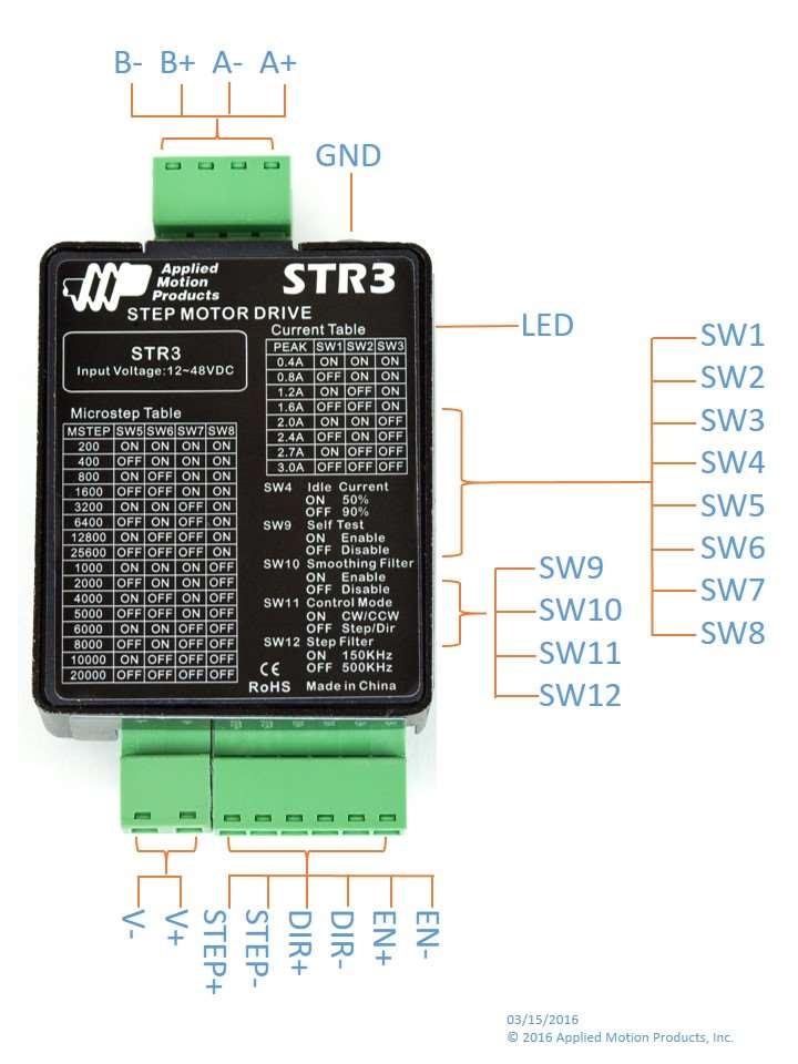
14 3.2 Connecting the Inputs & Outputs Connector Pin Diagram Power Inputs V- V+ STEP+ STEP- DIR+ DIR- EN+ EN STEP & DIR Inputs The STR3 step motor drive has two high speed optically isolated inputs called STEP and DIR. They accept 5 to 24 volt single-ended or differential signals, up to 500KHz. The maximum voltage that can be applied to the input is 28V. The motor executes one step when the STEP input closes. The direction of rotation is controlled by the DIR input state. A closed input (logic 0 ) will result in clockwise rotation, and an open input (logic 1 ) will result in counterclockwise rotation. +5v to +24v out DIR+ Indexer with Sinking Outputs DIR STEP DIR- STEP+ STEP- STR3 Connecting to Indexer with Sinking Outputs Indexer with Sourcing Outputs DIR COM STEP DIR+ DIR- STEP+ STR3 STEP- Connecting to Indexer with Sourcing Outputs Indexer with Differential Outputs DIR+ DIR- STEP+ STEP- DIR+ DIR- STEP+ STEP- STR3 Connecting to Indexer with Differential Outputs Many high-speed indexers have differential outputs 14
15 3.2.3 EN Input The EN input enables or disables the drive Amplifier. It is an optically isolated input that accepts a 5 to 24 volt single-ended or differential signal. The maximum voltage that can be applied to the input is 28V. When EN input is closed, the drive Amplifier is deactivated. All the MOSFETs will shutdown, and the motor is free. When EN input is open, the drive is activated. When the drive has encountered an error and the fault is removed from system, a falling signal into the EN input will reset the error status and activate the drive Amplifier again. 5~24V Power Supply + Switch or Relay (closed = logic low) EN+ - EN- STR3 Connecting the Input to a Switch or Relay 5~24V Power Supply NPN Proximity Sensor output EN+ EN- STR3 Connecting an NPN type Proximity Sensor to an input (when prox sensor activates, input goes low) 5~24V Power Supply PNP Proximity Sensor - output EN+ EN- STR3 Connecting an PNP type Proximity Sensor to an input (when prox sensor activates, input goes low) 15

16 4 Switch Selecting LED SW1-8 SW9-12 SW1 SW2 SW3 SW4 SW5 SW6 SW7 SW8 Running Current Idle Current Microstep SW9 SW10 SW11 SW12 Self Test Control Mode Step Smoothing Filter Step Noise Filter 4.1 Running Current The output current of the STR3 step motor drive is set by the SW1, SW2 and SW3 switches and can be changed as necessary. There are 4 settings available according to the ON/OFF combination of the switches. Current (Amps) SW1 SW2 SW3 0.4 ON ON ON 0.8 OFF ON ON 1.2 ON OFF ON 1.6 OFF OFF ON 2.0 ON ON OFF 2.4 OFF ON OFF 2.7 ON OFF OFF 3.0 OFF OFF OFF Current Setting SW1 SW SW

17 4.2 Idle Current The running current of the STR3 is automatically reduced whenever the motor isn t moving. Setting the SW4 switch to ON maintains 50% of the running current. Setting this switch to OFF maintains 90% of the running 4 4 current. This 90% setting is useful when a high holding torque is required. ON To minimize motor and drive heating it is highly recommended that the idle 90% current reduction feature be set to 50% unless the application requires the Idle Current higher setting. 4.3 Microstep Setting STR3 setting switch SW5, SW6, SW7, SW8. There are 16 settings. Steps/Rev SW5 SW6 SW7 SW8 200 ON ON ON ON 400 OFF ON ON ON 800 ON OFF ON ON 1600 OFF OFF ON ON 3200 ON ON OFF ON 6400 OFF ON OFF ON ON OFF OFF ON OFF OFF OFF ON 1000 ON ON ON OFF 2000 OFF ON ON OFF 4000 ON OFF ON OFF 5000 OFF OFF ON OFF 6000 ON ON OFF OFF 8000 OFF ON OFF OFF ON OFF OFF OFF OFF OFF OFF OFF Micorstep OFF 50% SW5 SW6 SW7 SW
18 4.4 Self Test A built-in self-test feature is available on the STR3 to check the physical operation of the motor. Setting switch SW9 to ON after the drive is powered up will cause the drive to perform a self test move of 2 revolutions both CW and CCW at 1rps. Setting switch SW9 to OFF 9 9 disables this feature. ON OFF SELF TEST 4.5 Step Smoothing Filter Command signal smoothing can soften the effect of immediate changes in velocity and direction, making the motion of the motor less jerky. An added advantage is that it can reduce the wear on mechanical components. SW10 selects this function - ON enables it, OFF disables it. This function can cause a small delay in following the control signal, and it should be used with that in mind ON OFF 4.6 Control Mode Switch SW11 sets control mode. Switch OFF sets the Step & Dir mode. Switch ON sets the CW/ CCW mode. 4.7 Step Noise Filter Switch SW12 sets the digital signal filter. The STEP and DIR signal inputs have built-in digital filters and this setting will reduce external noise. If the system works on the low microstep, select the 150 KHz (ON) setting. If the system works on the high microstep, select the 500KHz (OFF) setting ON OFF 150 KHz 500KHz 18


19 4.8 Motor election Motor wires setting: GND B- B+ A- A+ 4 LEAD BIPOLAR DRIVE Black A+ Green A- 4 LEAD Motor Red B+ Blue B- 19
20 5 Troubleshooting LED Error Codes The STR3 has one bicolor (red/green) LED to indicate status and errors. When the motor is enabled, the LED slowly flashes green. When the LED is solid green, the motor is disabled. If the LED flashes red, an error has occurred. Errors are indicated by a combination of red and green flashes as follows: Code Error Solid Motor Disabled Flashing Motor Enabled 3 red, 1 green Over Temperature 3 red, 2 green Bad Internal Voltage 4 red, 1 green Power Supply Over Voltage 4 red, 2 green Power Supply Under Voltage 5 red, 1 green Over Current/Short Circuit 6 red, 1 green Open Winding 20
21 6 Reference Materials 6.1 Mechanical Outline 21
22 6.2 Technical Specifications Amplifier Type Current Control Power Supply Input Voltage Range Protection Dual H-Bridge, 4 Quadrant 4 state PWM at 16 KHz Power Amplifier External volt power supply required volts min/max (nominal volts), voltages outside this range will cause driver faults and/or may damage the drive Over-voltage, over-current, under-voltage, over-temp, internal motor shorts (phase-to-phase, phase-to-ground) Ambient Temperature 0-40 C ( F) when mounted to a suitable heat sink Humidity 90% non-condensing Current Control Speed Range Auto Setup Step Input STEP+/- Direction Input DIR+/- Enable Input EN+/- Running Current Idle Current Reduction Microstep Resolution Self Test Modes Of Control Controller Advanced digital current control provides excellent high speed torque Speeds up to 3000 rpm Measures motor parameters to configure current control and anti-resonance gain settings Inputs: optically isolated, 5-24 volts, min. pulse width 250 us., max. pulse frequency 500KHz; motor executes one step when the STEP input closes Inputs: optically isolated, 5-24 volts, min. pulse width 62.5 us., max. pulse frequency 500KHz; direction of rotation is controlled by the DIR input state Inputs: optically isolated, 5-24 volts, min. pulse width 500 us., max. pulse frequency 10 KHz; enables or disables the drive Amplifier Switch selectable, 8 settings: 3 Amps peak maximum Automatically reduces the current 1 second after the motor stops; switch selectable, 2 settings: 50% or 90% of the running current Switch selectable, 16 settings: 200, 400, 800, 1600, 3200, 6400, 12800, , 2000, 4000, 5000, 6000, 8000, 10000, steps/rev Checks internal and external power supply voltages, 2 rev move both CW and CCW at 1rps, switch selectable, ON or OFF Step & Direction, CW/CCW 22
23 6.3 Torque Curves 23
24 Note: all torque curves were measured at 20,000 steps/rev. 24
25 6.4 Drive/Motor Heating Step motors convert electrical power from the driver into mechanical power to move a load. Because step motors are not 100% efficient, some of the electrical power turns into heat as it passes through the motor. The amount of heating is not so much dependent on the load being driven as on the motor speed and power supply voltage. There are certain combinations of speed and voltage at which a motor cannot be continuously operated without damage occurring to the motor. A step motor typically reaches its maximum temperature after 30 to 45 minutes of operation. A motor that runs for one minute and then rests for one minute is said to have a duty cycle of 50%. Five minutes of running and five minutes of rest is also a 50% duty cycle. However, one hour of running and one hour of rest has the effect of 100% duty cycle as the motor will reach full and possible excessive temperature during the first hour. The actual temperature of the motor depends on how much heat is conducted, converted or radiated out of it. The curves below result from measurements made in a 40 C (104 F) environment with the motor mounted to an aluminum plate sized to provide a surface area consistent with the motor power dissipation. Results may vary. 60 STR3 Motor HT Wattage VS Speed 1.65 ambient of 40 C 60x65x6(mm) Aluminum Plate 12V Watts 24V Watts 48V Watts 50 Power Supply (Watts) Power Supply (Watts) Speed (RPS) STR3 Motor HT Wattage VS Speed 2.25 ambient of 40 C 200x200x5(mm) Aluminum Plate 12V Watts 24V Watts 48V Watts Speed (RPS) 25
26 7 Contacting Applied Motion Products 404 Westridge Dr. Watsonville, CA 95076, USA Tel (831) Fax (831)
SR3-mini. Step Motor Drive User Manual. AMP & MOONS Automation
 SR3-mini Step Motor Drive User Manual AMP & MOONS Automation Contents 1 Introduction... 3 1.1 Overview...3 1.2 Features...3 1.3 Block Diagram...4 1.4 Safety Instructions...5 2 Getting Started... 6 2.1
DRV-1. Step Motor Drive. User Manual Mentor Avenue Cincinnati, Ohio Tel (513)
") DRV-1 Step Motor Drive User Manual 1776 Mentor Avenue Cincinnati, Ohio 45212 Tel (513) 318-4600 www.resolutionair.com 2 Contents 1 Introduction... 3 1.1 Overview... 3 1.2 Features... 3 1.3 Block Diagram...
DRV-1 Step Motor Drive User Manual 1776 Mentor Avenue Cincinnati, Ohio 45212 Tel (513) 318-4600 www.resolutionair.com 2 Contents 1 Introduction... 3 1.1 Overview... 3 1.2 Features... 3 1.3 Block Diagram...
MSD Phase Step Motor Drive User Manual
 MSD4822 2 Phase Step Motor Drive User Manual Contents 1 Introduction...3 1.1 Overview...3 1.2 Features...3 1.3 Block diagram...4 2 Mounting the Drive...4 3 Connections...5 3.1 Connector Diagram...5 3.2
SR8-Plus 2 Phase Step Motor Drive
 2 Phase Step Motor Drive User Manual Rev. 1.1 AMP & MOONS Automation Contents 1 Introduction... 3 1.1 Overview...3 1.2 Features...3 1.3 Block diagram...4 2 Mounting the Drive... 4 3 Connections... 5 3.1
SR4. 2 Phase Step Motor Drive. User Manual Rev AMP & MOONS Automation
 SR4 2 Phase Step Motor Drive User Manual Rev. 1.1 AMP & MOONS Automation Contents 1 Introduction...3 1.1 Overview...3 1.2 Features...3 1.3 Block diagram...4 2 Mounting the Drive...4 3 Connections...5 3.1
SR8. 2 Phase Step Motor Drive. User Manual Rev AMP & MOONS Automation
 SR8 2 Phase Step Motor Drive User Manual Rev. 1.1 AMP & MOONS Automation Contents 1 Introduction...3 1.1 Overview...3 1.2 Features...3 1.3 Block diagram...4 2 Mounting the Drive...4 3 Connections...5 3.1
Pluse Input Type Integrated Step Motor STM-R Series
 Pluse Input Type Step Motor Series Step Motor The is an integrated Drive+Motor, fusing step motor and drive technologies into a single device, offering savings on space, wiring and cost over conventional
User's Manual 1035D. 2 Axis Step Motor Driver. motors drives controls
 10/15/03 1035man.ai User's Manual 2 Axis Step Motor Driver axis 1 axis 2 3362 3362 Copyright 2003 Applied Motion Products, Inc. 404 Westridge Drive Watsonville, CA 95076 Tel (831) 761-6555 (800) 525-1609
KL-8070D. Fully Digital Stepping Driver. Table of Contents 1. Introduction, Features and Applications...1 Introduction...1 Features...
 Contents KL-8070D Fully Digital Stepping Driver Attention: Please read this manual carefully before using the driver! I Table of Contents 1. Introduction, Features and Applications...1 Introduction......1
Operating Manual For Stepper Driver
 Contents Table of Contents Operating Manual For Stepper Driver 5042 High Performance Micro stepping Driver Attention: Please read this manual carefully before using the driver! E L E C T R O N I C S 54
MondoStep 7.8. High Performance Microstepping Driver. User s Manual. Version PROBOTIX All Rights Reserved
 MondoStep 7.8 High Performance Microstepping Driver User s Manual Version 1.0 2010 PROBOTIX All Rights Reserved Attention: Please read this manual carefully before using the driver! Table of Contents 1.
User s Manual. For DM860T. Fully Digital Stepper Drive. Version 1.0 Designed by StepperOnline All Rights Reserved
 User s Manual For DM860T Fully Digital Stepper Drive Version 1.0 Designed by StepperOnline 2017 All Rights Reserved Web site: www.omc-stepperonline.com E-Mail: sales@stepperonline.com Table of Contents
Hardware Manual 1240i
 Hardware Manual Programmable Step Motor Driver motors drives controls -2- Introduction Thank you for selecting an Applied Motion Products motor control. We hope our dedication to performance, quality and
Artisan Technology Group is your source for quality new and certified-used/pre-owned equipment
 Artisan Technology Group is your source for quality new and certified-used/pre-owned equipment FAST SHIPPING AND DELIVERY TENS OF THOUSANDS OF IN-STOCK ITEMS EQUIPMENT DEMOS HUNDREDS OF MANUFACTURERS SUPPORTED
User s Manual. For DM542T. Full Digital Stepper Drive
 User s Manual For DM542T Full Digital Stepper Drive Designed by StepperOnline Manufactured by Leadshine 2017 All Rights ReservedAttention: Please read this manual carefully before using the drive! #7 Zhongke
User's Manual O
 11/3/99 3535.ai User's Manual 3535 3535 O Step Motor Drivers Copyright 1998 Applied Motion Products, Inc. 404 Westridge Drive Watsonville, CA 95076 Tel (831) 761-6555 (800) 525-1609 Fax (831) 761-6544
Features Block Diagram Specifications Typical Wiring Diagram Connection and Adjustment Locations...3 4
 SUESTEP STP-DV-4035 MICOSTEPPING DIVE CHAPTE 3 In This Chapter... Features.......................................32 Block Diagram...................................32 Specifications...................................33
User s Manual. For M542. High Performance Microstepping Driver. Version All Rights Reserved
 User s Manual For M542 High Performance Microstepping Driver Version 1.0.2011 All Rights Reserved Attention: Please read this manual carefully before using the driver! Easy Commercial Global Technology
Manual of SM442. High Performance Microstepping Driver. Nietz Electric Co.,Ltd.
 Manual of SM442 Nietz Electric Co.,Ltd. Add: No.988, Fulian Rd., Gucun Industry, Baoshan District, Shanghai, China201100 High Performance Microstepping Driver CATALOG 1. Introduction... 1 Introduction...
User s Manual-M752. Stepper Motor Driver. Version All Rights Reserved. Attention: Please read this manual carefully before using the driver!
 User s Manual-M752 Stepper Motor Driver Version 1.0 2006 All Rights Reserved Attention: Please read this manual carefully before using the driver! Table of Contents 1. Introduction, Features and Applications
DR8010 tm. Hardware Reference Manual. Document Revision B4 May 15, 2018
 tm Hardware Reference Manual Document Revision B4 May 15, 2018 3380 Town Point Drive Suite 330 Kennesaw, GA 30144 Tel: (770) 422-7845 Fax: (770) 422-7854 www.microkinetics.com Table of Contents 1 The Driver
LN3 Series Motor and Drives
 LN3 Series Motor and Drives Operator's Manual PN 04-01906 C PRECISION MOTION CONTROLS 2175 De La Cruz Blvd. #1 Santa Clara, CA 95050 LN3 Manual CONTENTS Introduction... 3 Description... 3 Features... 3
User's Manual. For M542T. High Performance Microstepping Driver. Version All Rights Reserved
 User's Manual For M542T High Performance Microstepping Driver Version 1.0.2011 All Rights Reserved Attention: Please read this manual carefully before using the driver! 1. Introduction, Features and Applications
DMX-A2-DRV Integrated Advanced Step Motor Driver
 DMX-A2-DRV Integrated Advanced Step Motor Driver DMX-A2-DRV Manual page 1 rev 3.10 COPYRIGHT 2008 ARCUS, ALL RIGHTS RESERVED First edition, May 2008 ARCUS TECHNOLOGY copyrights this document. You may not
RHINO MOTION CONTROLS
 Installation Manual and Datasheet http://www.rhinomotioncontrols.com Page 1 [] Key Features Smooth and quiet operation at all speeds and extremely low motor heating Industrial grade performance for 2-Phase
LNII Series Motor and Drives
 LNII Series Motor and Drives Operator's Manual PN 04-01805 B PRECISION MOTION CONTROLS 2530 Berryessa Rd. #209 San Jose, CA 95132 10/04/05 2 2 LNII Manual Table of Contents Page Introduction 1. Description
SMD10 SMD11 SMD15 SMD30
 SMD10 SMD11 SMD15 SMD30 Step Motor Drivers User Manual JVL Industri Elektronik A/S - January 1992 LB0009-02GB Revision 11th Feb 98 Contents 1.1 Introduction 2 1.2 Overview of Driver Models 3 1.3 Front
User Manual of 2MA2282
 ECG-SAVEBASE EMAIL:EBAY@SAVEBASE.COM WEB: HTTP://STORES.EBAY.CO.UK/SAVEBASE User Manual of 2MA2282 High Performance Microstepping Driver ECG-SAVEBASE ECG Safety Statement Easy Commercial Global is not
G213V STEP MOTOR DRIVE REV 7: March 25, 2011
 Thank you for purchasing the G213V drive. The G213V is part of Geckodrive s new generation of CPLD-based microstep drives. It has short-circuit protection for the motor outputs, over-voltage and under-voltage
ZETA advanced microstep drive. Microstepping systems - the next generation... Automation. Quicker settling following a speed change
 ZETA-2 advanced microstep drive Microstepping systems - the next generation... The new ZETA series drives from Parker represent a true revolution in microstep drive design. Incorporating breakthrough techniques
R A, 80V Microstepping Driver The PowerHouse
 R1025 10A, 80V Microstepping Driver The PowerHouse User Manual Version 1.00 RMS Technologies 2533 N. Carson St. #4698, Carson City, NV 89706-0147 Thank you for purchasing the R1025 Single-Axis Step & Direction
USER'S MANUAL MODEL DPD60001 MICROSTEP DRIVER PACK
 COPYRIGHT Copyright 1997 by Anaheim Automation. All rights reserved. No part of this publication may be reproduced, transmitted, transcribed, stored in a retrieval system, or translated into any language,
G203V / G213V MANUAL STEP MOTOR DRIVE
 G203V / G213V MANUAL STEP MOTOR DRIVE PRODUCT DIMENSIONS PHYSICAL AND ELECTRICAL RATINGS Minimum Maximum Units Supply Voltage 18 80 VDC Motor Current 0 7 A Power Dissipation 1 13 W Short Circuit Trip 10
User Manual. Model P403. High Performance Microstepping Driver
 User Manual Model P403 High Performance Microstepping Driver 1. General The P403 is a high performance microstepping driver based on the most advanced technology in the world today. It is suitable for
User s Manual. For. BH-MSD-4.5A Micro Stepping Driver
 User s Manual For BH-MSD-4.5A Micro Stepping Driver Product Number Code For Micro step drive Page 2 BH MSD 4.5A BHOLANATH MICRO STEP DRIVE 4.5 Amp 1:DC power input :20V~50VDC 2.Output current:1.5a-4.5a
User s Manual. For. BH-MSD-2A Micro Stepping Driver
 User s Manual For BH-MSD-2A Micro Stepping Driver Product Number Code For Micro step drive Website:-www.bholanath.in Page 2 BH MSD 2A BHOLANATH MICRO STEP DRIVE 2 Amp 1:DC power input :12V~36VDC 2.Output
Kelly KDHA High Voltage Series/PM Motor Controller User s Manual
 Kelly KDHA High Voltage Series/PM Motor Controller User s Manual KDH07500A KDH07501A KDH07700A KDH07701A KDH09400A KDH09401A KDH09500A KDH09501A KDH12400A KDH12401A KDH12500A KDH12501A KDH14300A KDH14301A
DM320C. User s Manual. Fully Digital Stepping Driver. For. Version All Rights Reserved
 User s Manual For DM320C Fully Digital Stepping Driver Version 1.0 2009 All Rights Reserved Attention: Please read this manual carefully before using the driver! The content in this manual has been carefully
User Manual. T6 Tachometer. Online: Telephone: P.O. Box St. Petersburg, Florida 33736
 User Manual T6 Tachometer Online: www.phareselectronics.com Telephone: 727-623-0894 P.O. Box 67251 St. Petersburg, Florida 33736 Table of Contents Overview... 1 Description... 1 Wiring... 1 T6 Tachometer
Kelly HSR Series Motor Controller with Regen User s Manual V 3.3. Kelly HSR Opto-Isolated Series Motor Controller with Regen.
 Kelly HSR Opto-Isolated Series Motor Controller with Regen User s Manual HSR72601 HSR72801 HSR12401 HSR12601 HSR12901 HSR14301 HSR14501 HSR14701 Rev.3.3 Dec. 2011 Contents Chapter 1 Introduction... 2 1.1
M545D. Stepper Motor Driver Specification. Overview. Applications
 M545D Stepper Motor Driver Specification Overview The M545D is a new generation microstep stepper motor driver. Due to the adoption of the advanced bipolar constant-current chopper driver technology, it
RP-4000 Reserve Power Control
 Instruction Manual IM-0580 RP-4000 Reserve Power Control Table of Contents General Information... 2-3 Introduction... 2 Cautions... 2 Receiving/Inspection... 2 Storage... 2 Equipment Return... 2 Identification
Efficiency (typ.) (Range) Output Voltage Current. Input Current Load VDC VDC ma ma ma(typ.) ma(typ.) ma(typ.
 (Range) Output Voltage Current. Input Current Load VDC VDC ma ma ma(typ.) ma(typ.) ma(typ.") FEATURES 2"x 1"x 0.4" Metal Package Wide 2:1 Input Range High Efficiency up to % Operating Ambient Temp. Range 40 C to 80 C Short Circuit Protection I/O-isolation 1500 VDC Input Filter meets EN 55022,class
FEATURES 2"x 1"x 0.4" Metal Package Wide 2:1 Input Range High Efficiency up to % Operating Ambient Temp. Range 40 C to 80 C Short Circuit Protection I/O-isolation 1500 VDC Input Filter meets EN 55022,class
MD24 / MD28 Microstepping Driver odul
 MD24 / MD28 Microstepping Driver odul Instruction Manual Hardware Description Item-no. 970317 BE001 Last update: 01/2010 isel Germany AG D-36124 Eichenzell Bürgermeister-Ebert-Str. 40 +49/(0)6659/981-700
PKG-341-MBC08-PS-CBL System Diagram and Specifications
 PKG-341-MBC8-PS-CBL System Diagram and Specifications Included Components: 34Y112S-LW8-MS Stepper Motor MBC82561 Stepper Driver PSA8V4A-1 Power Supply CBL-18AWG-4C-1-MS Motor Cable WIR-17-18-YEL Power
BLDC SPEED CONTROL INSTRUCTION MANUAL Line voltage Brushless DC control
 BLDC SPEED CONTROL INSTRUCTION MANUAL Line voltage Brushless DC control Phone 712.722.4135 groschopp.com 420 15th St NE, Sioux Center, IA 51250 Toll-Free 800.829.4135 Email sales@groschopp.com FAX 712.722.1445
Table 1: 2-pin Terminal Block J1 Functional description of BSD-02LH Module Pin # Pin Description Table 2: 10-pin Header J2 Pin # Pin Description
 Functional description of BSD-02LH Module The BSD-02LH module is the part of the BSD-02 family of drivers. The main difference is higher microstepping resolution. The BSD-02LH is suitable for driving bipolar
CENTROIDTM. AC Brushless Drive. Product Spec Sheet
 4 Axis, up to 2 KW motors Brake Output for each axis Overtemp and Overcurrent Protection All-software Configuration Self-cooled Fiber Optic Control CENTROIDTM AC Brushless Drive Product Spec Sheet AC Brushless
CB-005N Circuit Board
 CB-005N Circuit Board Provides Thermal Protection for board and motor Built-in current limiter Error Output signal for self diagnosis Dynamic brake control Variable speed (0% - 100%) by onboard potentiometer
Kelly HPM High Power Full Bridge Permanent Magnet DC Motor Controller User s Manual
 Kelly HPM High Power Full Bridge Permanent Magnet DC Motor Controller User s Manual HPM72601 HPM72801 HPM12401 HPM12601 HPM12801 HPM14301 HPM14501 HPM14701 Rev.3.4 Dec. 2016 Contents Chapter1 Introduction...
Products Tde Macno. User s Manual BRAKING UNIT. Cod. MP00401E00 V_1.0
 Products Tde Macno User s Manual BRAKING UNIT Cod. MP00401E00 V_1.0 SUMMARY 1 GENERAL DESCRIPTION... 2 2 USE LIMITATIONS... 2 2.1 Climatic Class... 2 2.2 Resistance To Chemically Active Substances...
Motor/Drive Configuration
 ZX900 Electrical Specifications Input Power Output Power Electrical specifications for the ZX900 series drive's input and output power are provided in this section. Voltage (Nominal) Voltage (Range) Frequency
LinStep Microstepping Driver
 LINEAR DRIVE LinStep Microstepping Driver Installation & Operating Manual 3/01 Table of Contents Section 1 General Information.............................................................. 1-1 CE Compliance...............................................................
User s Manual. Table of Contents. Low Cost Microstepping Driver 9. Connection Diagram for Driver, Motor, Controller 12
 Table of Contents User s Manual 1. Introduction, Features and Applications 1 2. Specifications and perating Environment 2 For 3. Driver Connectors P1 and P2 3 WS-2H542M 4. Control Signal Connector (P1)
Output Voltage Current. Input Current Ripple. Efficiency (typ.) Load VDC VDC ma ma ma(typ.) ma(typ.) ma(typ.) μf % 2.
 Load VDC VDC ma ma ma(typ.) ma(typ.) ma(typ.) μf % 2.") FEATURES Industrial Standard 2" X 1" Package Wide 2:1 Input Voltage Range Fully Regulated Output Voltage High Efficiency up to 88% I/O Isolation 1500 VDC Operating Ambient Temp. Range -40 to 85 Overload
FEATURES Industrial Standard 2" X 1" Package Wide 2:1 Input Voltage Range Fully Regulated Output Voltage High Efficiency up to 88% I/O Isolation 1500 VDC Operating Ambient Temp. Range -40 to 85 Overload
ATOTH-G Series BLDC Motor Controller. User s Manual
 ATOTH-G Series BLDC Motor Controller User s Manual Contents Chapter One Summary...1 Chapter Two Main Features and Specifications.2 2.1 Basic Functions...2 2.2 Features... 5 2.3 Specifications...6 Chapter
17429X.00 SERIES MODELS:
 LEESON ELECTRIC MOTORS, GEARMOTORS AND DRIVES R User s Manual 17429X.00 SERIES MODELS: 174298.00 174299.00 PWM REGENERATIVE DC TO DC DRIVES II Table of Contents 17429X.00 Drives...............................................................
MLA Bipolar Microstep Driver. User s Guide. 910 East Orangefair Lane, Anaheim, CA
 MLA05101 Bipolar Microstep Driver User s Guide A N A H E I M A U T O M A T I O N 910 East Orangefair Lane, Anaheim, CA 92801 e-mail: info@anaheimautomation.com (714) 992-6990 fax: (714) 992-0471 website:
Kelly KDC Series/PM Motor Controller User s Manual
 Kelly KDC Series/PM Motor Controller User s Manual KDC48600 KDC48601 KDC48602 KDC48603 KDC72600 KDC72601 KDC72602 KDC72603 KDC72800 KDC72801 KDC72802 KDC72803 KDC12602 KDC12603 Rev.3.3 May 2011 Contents
Pulse Encoder Interface Kit For Use With FlexPak 3000 and WebPak 3000 DC Drives M/N 907FK0101
 Pulse Encoder Interface Kit For Use With FlexPak 3000 and WebPak 3000 DC Drives M/N 907FK0101 Instruction Manual D2-3302-3 The information in this manual is subject to change without notice. Throughout
715B CONTROL SERIES. Instruction Manual Line Voltage DC Brushless Motor Control CONTROLS. Phone (317) Fax (317)
 Fax (317)") 715B CONTROL SERIES CONTROLS Instruction Manual Line Voltage DC Brushless Motor Control LT715B (IM-715B-0100) P.O. Box 10 5000 W. 106th Street Zionsville, Indiana 46077 Phone (317) 873-5211 Fax (317) 873-1105
715B CONTROL SERIES CONTROLS Instruction Manual Line Voltage DC Brushless Motor Control LT715B (IM-715B-0100) P.O. Box 10 5000 W. 106th Street Zionsville, Indiana 46077 Phone (317) 873-5211 Fax (317) 873-1105
Battery Charger Retrofit Kit Q-DCCHG1 for DC Cabinet Retrofit Manual
 Battery Charger Retrofit Kit Q-DCCHG1 for DC Cabinet Retrofit Manual 25500181 Rev. A0 415 Printed in U.S.A. Copyright 2015 Federal Signal Corporation Limited Warranty The Alerting and Notification Systems
CBM-105FN/FP Circuit Board
 CBM-105FN/FP Circuit Board Features Adjustable acceleration and deceleration time (0 to 2.5s) Stable speed operation Manual or automatic recovery of the thermal overload device One (1) rotary switch to
Full Bridge Permanent Magnet DC Motor Controller User's Manual
 www.igreatway.com Email:info@igreatway.com V 3.3 Full Bridge Permanent Magnet DC Motor Controller User's Manual PM24101 PM24201 PM24301 PM36101 PM36201 PM48101 PM48201 PM48301 PM48401B PM48501B PM72101
INSTRUCTION MANUAL FOR. VOLTAGE REGULATOR Model: APR Part Number:
 INSTRUCTION MANUAL FOR VOLTAGE REGULATOR Model: APR 125-5 Part Number: 9 1688 00 100 Publication Number: 9 1688 00 990 Revision H: 07/2001 CONTENTS SECTION 1 GENERAL INFORMATION...1-1 DESCRIPTION... 1-1
DPS32001 and DPS32PS1
 DPS32001 and DPS32PS1 Driver Pack User s Guide A N A H E I M A U T O M A T I O N 4985 E. Landon Drive Anaheim, CA 92807 e-mail: info@anaheimautomation.com (714) 992-6990 fax: (714) 992-0471 website: www.anaheimautomation.com
MICRO CONTROLS INC. ADVANCED. Table of Contents. Manual #: 940-0S064
 ADVANCED MICRO CONTROLS INC. Manual #: 940-0S064 Table of Contents General Information... 2 Introducing the SD17060B... 3 Specifications... 6 UL/CUL Recognized Installations... 7 Mounting the SD17060B...
MJWI20 SERIES FEATURES PRODUCT OVERVIEW. DC/DC Converter 20W, Highest Power Density MINMAX MJWI20 Series
 DC/DC 2W, Highest Power Density MINMAX MJWI2 Series MJWI2 SERIES DC/DC CONVERTER 2W, Highest Power Density FEATURES Smallest Encapsulated 2W! Package Size 1. x1. x.4 Ultra-wide 4:1 Input Range Very high
B-PC20 Power Close Module
 B-PC20 Power Close Module Instruction Manual Document number: B-PC20-C Release: V1.2 Date: OCT 12,2011 ! WARNING This control must be adjusted/serviced by a qualified person. The service technician must
User Manual. Solar Charge Controller 3KW
 User Manual Solar Charge Controller 3KW 1 CONTENTS 1 ABOUT THIS MANUAL... 3 1.1 Purpose... 3 1.2 Scope... 3 1.3 SAFETY INSTRUCTIONS... 3 2 INTRODUCTION... 4 2.1 Features... 4 2.2 Product Overview... 5
INSTALLATION INSTRUCTIONS for SLO-SYN MODELS SS2000MD7 & SS2000MD7-128 TRANSLATOR/DRIVE
 INSTALLATION INSTRUCTIONS for SLO-SYN MODELS SS2000MD7 & SS2000MD7-128 TRANSLATOR/DRIVE TABLE OF CONTENTS Page THINGS TO KNOW BEFORE USING THIS EQUIPMENT... 3 WARRANTY RESTRICTIONS... 3 SECTION 1: INTRODUCTION...
The information in this chapter will enable you to: 90VAC to Low voltage fault below 85VAC
 C H A P T E R ➅ Hardware Reference Chapter Objectives Environmental Specifications Drive Temperature Motor Temperature Humidity The information in this chapter will enable you to: Use this chapter as a
PowerOhm Installation Manual for BM R Series Braking Modules
 PowerOhm Installation Manual for BM R Series Braking Modules IMPORTANT: These instructions should be read thoroughly before installation. All warnings and precautions should be observed for both personal
Small Full Bridge Permanent Magnet Motor DC Controller User Manual
 Small Full Bridge Permanent Magnet Motor DC Controller User Manual SPM24051X SPM24101X SPM24121X SPM48051X SPM48101X SPM48121X SPM72051X SPM72101X SPM72121X SPM48151E SPM48181E SPM48221E SPM72151E SPM72181E
OPERATOR TROUBLESHOOTING GUIDE
 OPERATOR TROUBLESHOOTING GUIDE ABOUT THE TROUBLESHOOTING GUIDE This document is provided for the use of qualified operator installers. The installer should familiarize themselves with this guide Options
Features IN THIS CHAPTER
 CHAPTER THREE 3Special Features IN THIS CHAPTER Motor Braking Regeneration Solutions Sharing the Power Bus: V Bus+ and V Bus- Current Foldback (I T Limit) Front Panel Test Points Resolver Alignment ➂ Special
PowerOhm Installation Manual for LG ATV Series Braking Modules
 PowerOhm Installation Manual for LG ATV Series Braking Modules IMPORTANT: These instructions should be read thoroughly before installation. All warnings and precautions should be observed for both personal
C H A P T E R ➂. Installation. Installation Precautions. Environmental Considerations. Wiring Considerations
 C H A P T E R ➂ Installation Installation Precautions The information in this chapter will enable you to: Ensure that the complete system is installed correctly Mount all system components properly Before
BLHV, BLHV-1. High Voltage Step Motor Driver. User s Guide. (714) fax: (714) website:
 fax: (714) website:") BLHV, BLHV-1 High Voltage Step Motor Driver User s Guide A N A H E I M A U T O M A T I O N 910 East Orangefair Lane, Anaheim, CA 92801 e-mail: info@anaheimautomation.com #L010015 (714) 992-6990 fax: (714)
BLHV, BLHV-1 High Voltage Step Motor Driver User s Guide A N A H E I M A U T O M A T I O N 910 East Orangefair Lane, Anaheim, CA 92801 e-mail: info@anaheimautomation.com #L010015 (714) 992-6990 fax: (714)
Output Current Input Current Reflected Ripple. Efficiency (typ.) Load VDC VDC ma ma ma(typ.) ma(typ.) ma (typ.) VDC μf % MKW40-12S033
 Load VDC VDC ma ma ma(typ.) ma(typ.) ma (typ.) VDC μf % MKW40-12S033") MKW SERIES DC/DC CONVERTER W, Highest Power Density FEATURES Smallest Encapsulated W Ultra-compact 2" X 1" Package Wide 2:1 Input Voltage Range Fully Regulated Output Voltage Excellent Efficiency up to
MKW SERIES DC/DC CONVERTER W, Highest Power Density FEATURES Smallest Encapsulated W Ultra-compact 2" X 1" Package Wide 2:1 Input Voltage Range Fully Regulated Output Voltage Excellent Efficiency up to
USERS GUIDE CSMD2 U440 (UNIPOLAR DRIVE) CSMD2 B440 (BIPOLAR DRIVE) CONVEX Microstep Driver FOR 2PH Step Motor < CONTENTS >
 CSMD2 B440 (BIPOLAR DRIVE) CONVEX Microstep Driver FOR 2PH Step Motor < CONTENTS >") CONVEX Microstep Driver FOR 2PH Step Motor CSMD2 U440 (UNIPOLAR DRIVE) CSMD2 B440 (BIPOLAR DRIVE) Manual no. CSMD2_440CE-ENG 991127 USERS GUIDE < CONTENTS > 1. Safety Cautions P.2 2. Unpacking and Inspection
CONVEX Microstep Driver FOR 2PH Step Motor CSMD2 U440 (UNIPOLAR DRIVE) CSMD2 B440 (BIPOLAR DRIVE) Manual no. CSMD2_440CE-ENG 991127 USERS GUIDE < CONTENTS > 1. Safety Cautions P.2 2. Unpacking and Inspection
DMD4022. User s Manual. Fully Digital Stepping Driver. For. Version All Rights Reserved
 User s Manual For DMD4022 Fully Digital Stepping Driver Version 1.0 2009 All Rights Reserved Attention: Please read this manual carefully before using the driver! Contents The content in this manual has
R820 REV2 SERIES SCR POWER CONTROLS NOVEMBER 2017
 R80 REV SERIES SCR POWER CONTROLS NOVEMBER 017 Product overview The Viconics R80 series SCR power controls are designed for cost effective, precise modulation of electric loads for most electric heating
Output Current Input Current Reflected Ripple. Efficiency (typ.) Load VDC VDC ma ma ma(typ.) ma(typ.) ma (typ.) VDC μf % MKW40-12S033
 Load VDC VDC ma ma ma(typ.) ma(typ.) ma (typ.) VDC μf % MKW40-12S033") DC/DC High Efficiency Regulated Output W Minmax MKW Series FEATURES Smallest Encapsulated W Ultra-compact 2" X 1" Package Wide 2:1 Input Voltage Range Fully Regulated Output Voltage Excellent Efficiency
DC/DC High Efficiency Regulated Output W Minmax MKW Series FEATURES Smallest Encapsulated W Ultra-compact 2" X 1" Package Wide 2:1 Input Voltage Range Fully Regulated Output Voltage Excellent Efficiency
(typ.) (Range) ±18 330# 89 MPW MPW
 (Range) ±18 330# 89 MPW MPW") DC/DC 30W, Single & Dual Output FEATURES 2 x 1.6 x 0.4 Metal Package Ultra-wide 4:1 Input Range Operating Temp. Range 40 C to 80 C Short Circuit Protection I/O-isolation 1500 VDC Input Filter meets EN
DC/DC 30W, Single & Dual Output FEATURES 2 x 1.6 x 0.4 Metal Package Ultra-wide 4:1 Input Range Operating Temp. Range 40 C to 80 C Short Circuit Protection I/O-isolation 1500 VDC Input Filter meets EN
INSTRUCTION MANUAL FOR VOLTAGE REGULATOR APR P/N
 INSTRUCTION MANUAL FOR VOLTAGE REGULATOR APR 125-5 P/N 9168800100 Publication: 9168800990 Revision: J 03/09 INTRODUCTION This instruction manual provides information about the operation and installation
5001TCP SPEED CONTROLLER
 VARIABLE SPEED DRIVE CONTROLLER INSTALLATION AND SETTING UP MANUAL 5001TCP SPEED CONTROLLER With PC101 Torque Limit Control WARNING Disconnect all incoming power before working on this equipment. Follow
VDC VDC ma ma ma(typ.) ma(typ.) ma (typ.) VDC μf % MKW40-12S
 ma(typ.) ma (typ.) VDC μf % MKW40-12S") MKW SERIES DC/DC CONVERTER W, Highest Power Density FEATURES Smallest Encapsulated W Ultra-compact 2" X 1" Package Wide 2:1 Input Voltage Range Fully Regulated Output Voltage Excellent Efficiency up to
MKW SERIES DC/DC CONVERTER W, Highest Power Density FEATURES Smallest Encapsulated W Ultra-compact 2" X 1" Package Wide 2:1 Input Voltage Range Fully Regulated Output Voltage Excellent Efficiency up to
User s Manual-M860. Stepper Motor Driver. Version All Rights Reserved. Attention: Please read this manual carefully before using the driver!
 User s Manual-M860 Stepper Motor Driver Version 1.0 2006 All Rights Reserved Attention: Please read this manual carefully before using the driver! Sunwind Electronics Company Ltd. Add:7th Floor,Block H,Juyin
MDC V, 30A Brushless Controller. User s Guide L East Orangefair Lane, Anaheim, CA
 MDC150-012301 12V, 30A Brushless Controller User s Guide A N A H E I M A U T O M A T I O N 910 East Orangefair Lane, Anaheim, CA 92801 e-mail: info@anaheimautomation.com (714) 992-6990 fax: (714) 992-0471
DPD72001, DPD Unipolar Step Motor Driver. User s Guide E. Landon Drive Anaheim, CA
 DPD72001, DPD72002 Unipolar Step Motor Driver User s Guide A N A H E I M A U T O M A T I O N 4985 E. Landon Drive Anaheim, CA 92807 e-mail: info@anaheimautomation.com (714) 992-6990 fax: (714) 992-0471
(typ.) (Range) Input Specifications Parameter Model Min. Typ. Max. Unit 12V Input Models Input Surge Voltage (100ms.
 (Range) Input Specifications Parameter Model Min. Typ. Max. Unit 12V Input Models Input Surge Voltage (100ms.") FEATURES Smallest Encapsulated 50W! Package Size 2.0 x 1.0 x 0.4 Wide 2:1 lnput Range Excellent Efficiency up to 92% Over-Temperature Protection I/O-isolation Voltage 1500VDC Remote On/Off Control Shielded
FEATURES Smallest Encapsulated 50W! Package Size 2.0 x 1.0 x 0.4 Wide 2:1 lnput Range Excellent Efficiency up to 92% Over-Temperature Protection I/O-isolation Voltage 1500VDC Remote On/Off Control Shielded
MBDC V. 110VAC Input Brush DC Controller. User s Guide East Landon Drive, Anaheim, CA
 MBDC050-024031-120V 110VAC Input Brush DC Controller User s Guide A N A H E I M A U T O M A T I O N 4985 East Landon Drive, Anaheim, CA 92807 e-mail: info@anaheimautomation.com (714) 992-6990 fax: (714)
5001TCP SPEED CONTROLLER
 INSTALLATION AND SETTING UP MANUAL 5001TCP SPEED CONTROLLER WARNING Disconnect all incoming power before working on this equipment. Follow power lockout procedures. Use extreme caution around electrical
The information in this chapter will enable you to: 90VAC to 50/60 Hz
 C H A P T E R ➃ Hardware Reference The information in this chapter will enable you to: Use this chapter as a quick-reference tool for most system specifications (dimensions and performance) Use this chapter
(typ.) (Range) Load
 (Range) Load") FEATURES Highest Power Density 1" x 1" x 0.4" Shielded Metal Package Wide 2:1 Input Range Excellent Efficiency up to % Operating Temp. Range - C to + C Optional Heatsink I/O-isolation Voltage 10VDC Remote
FEATURES Highest Power Density 1" x 1" x 0.4" Shielded Metal Package Wide 2:1 Input Range Excellent Efficiency up to % Operating Temp. Range - C to + C Optional Heatsink I/O-isolation Voltage 10VDC Remote
CONTROL FEATURES AVAILABLE OPTIONS
 Vari Speed A2000 TABLE OF CONTENTS Control Features Options Application Data Operating Condition s Control Ratings Chart Mounting Dimensions Installation and Wiring Typical Wiring Diagram Schematic (Block
XLR Energy Storage Module
 Technical Note 19 XLR Energy Storage Module XLR Energy Storage Module Safety The XLR 48 V module contains stored energy of 54 watt-hours and can discharge up to 97 amps if short circuited. Only personnel
dv Sentry TM 208V 600V INSTALLATION GUIDE Quick Reference ❶ How to Install Pages 6 14 ❷ Startup/Troubleshooting Pages WARNING
 dv Sentry TM 208V 600V INSTALLATION GUIDE FORM: DVS-IG-E REL. January 2018 REV. 003 2018 MTE Corporation High Voltage! Only a qualified electrician can carry out the electrical installation of this filter.
User Manual Solar Charge Controller 3KW
 User Manual Solar Charge Controller 3KW Version: 1.3 CONTENTS 1 ABOUT THIS MANUAL... 1 1.1 Purpose... 1 1.2 Scope... 1 1.3 SAFETY INSTRUCTIONS... 1 2 INTRODUCTION... 2 2.1 Features... 2 2.2 Product Overview...