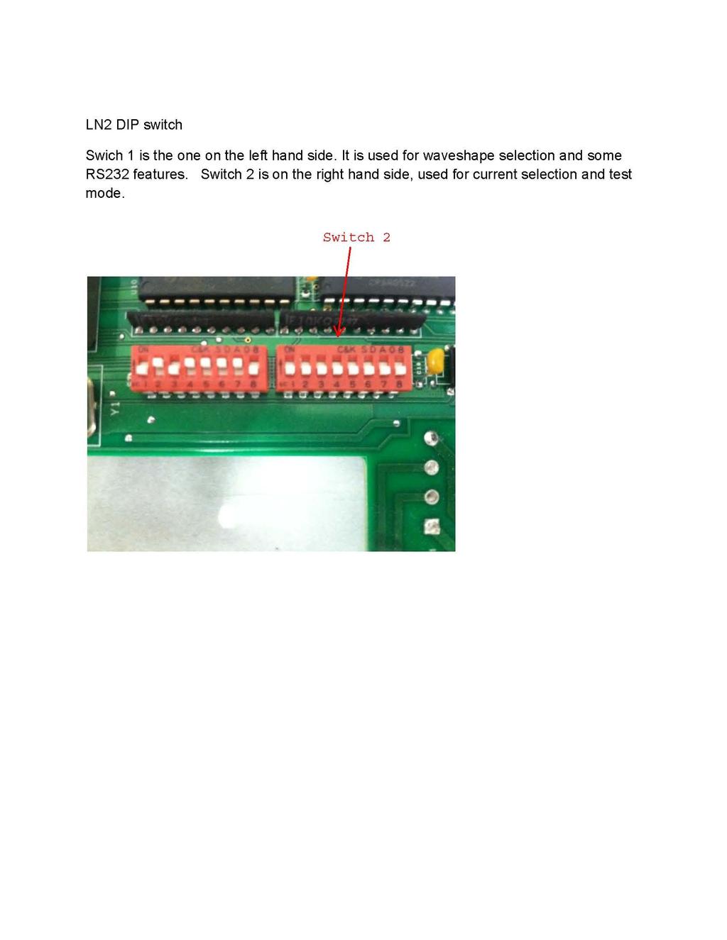
LNII Series Motor and Drives
|
|
|
- Victor Booker
- 5 years ago
- Views:
Transcription
1 LNII Series Motor and Drives Operator's Manual PN B PRECISION MOTION CONTROLS 2530 Berryessa Rd. #209 San Jose, CA /04/05
2 2 2
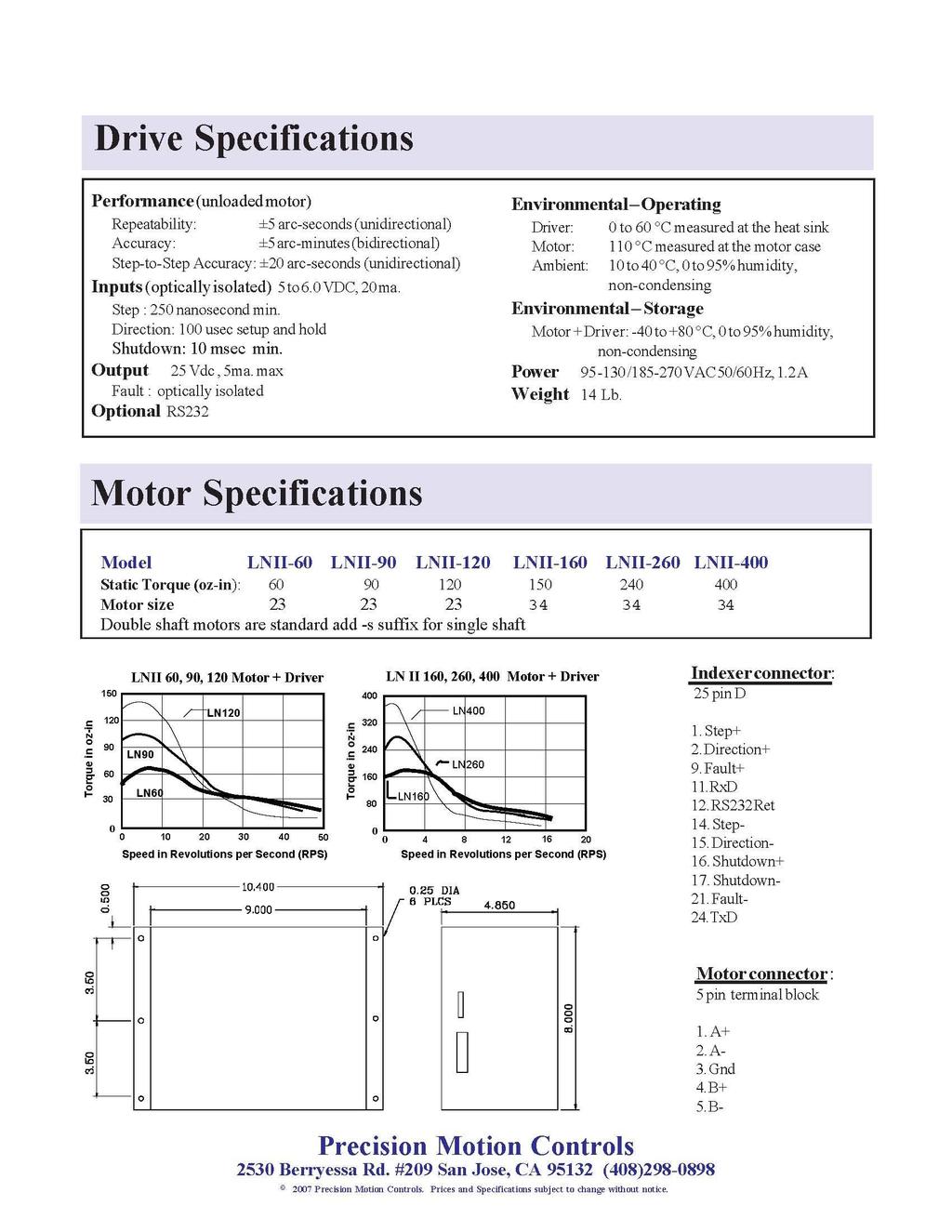
3 LNII Manual Table of Contents Page Introduction 1. Description 3 2. Warranty 4 Installation 1. Unpacking 5 2. Mounting 5 3. Cooling ` 5 4. Wiring A. Motor Connections 6 B. Line Power 6 C. Indexer Connections 6 D. Switch Settings 7 Operation 1. Electrical 9 2. Motor Compatibility 9 3. Indexer Inputs Resonances 10 Appendixes A LN Specifications 11 B Dimensions and Torque Curves
4 INTRODUCTION Description The LNII Drive is a microstepping drive with a linear amplifier for the output stage. It is intended for stepping motor applications where motor vibration must be minimized and EMI noise can't be tolerated. The LNII drive eliminates EMI generated noise in the steady state condition and minimizes EMI noise while running. The drives dual voltage supply design, allows this unit to have speed vs torque curves superior to most pulsewidth modulated drives; while minimizing the stress on the power amplifier. Extremely smooth movement is provided with a microstepping resolution of up to steps/revolution; this makes this product suitable in applications with precision equipment where vibration must be minimized. The LNII Drive can be bought with a wide range of motors, with torque ranging from 60 to 600 in-oz. The drive has two dip switches for easy access to current selection, step size, auto-shutdown, 3rd harmonic correction, and a test mode. Each function is described in detail further on in the manual. A standard 25 pin D connector with step, direction, and remote disable inputs make this drive easy to interface with existing indexers on the market. The remote disable input removes power from the drive so that the motor can be turned by hand. This may also be used as a safety limit since it overrides any of the other drive signals. The Two fault indicators indicate various motor conditions. LED1 on means that a overcurrent, over-temperature, or low-voltage condition has occurred; this is a fatal error and power must be turned off and then back on for the drive to continue operation. LED 2 on indicates that current is not on the motor (ie the shut down signal is active). A optional RS232 connection on the 25 pin "D" connector makes it possibly to accept simple commands for special application. Consult the factory if you would need this feature. Features The LNII is a high performance linear Microstepping drive designed for low noise applications. The systems dual supply allows cool operation at idle and low speed operation yet still enables the drive to obtain high speeds. * Wave shape correction of 3%, 6% third harmonic distortion * 115/220 VAC line voltage operation 4 4
5 * Auto-standby reduces motor current to 1/2 after 2 seconds if no input is received. * 2 Mhz step input rate (0.25 usec min width high or low) * 8 selectable step sizes * Short circuit current protection * Low voltage sense Warranty PMC's linear drives have a one year warranty against manufacturing defects from the date of purchase. If your unit should ever fail, and you wish to send it back for repairs; you should do the following: 1. Get the serial number from the defective unit. 2. Check purchase date to see if the unit is under warranty. If not, obtain a purchase order number for repair costs. 3. Call Precision Motion Controls for a return authorization (408) Ship to : Precision Motion Controls 2530 Berryessa Rd. #209 San Jose, CA Attention RMA # 5 5
6 INSTALLATION Unpacking When unpacking your unit verify that the unit was not damaged during shipping. Report any damage found to the shipper. Check the box contents against the packing slip. The box will contain the driver, an AC line cord and manual. If a complete system was bought a motor will also be included. Connect the motor to the driver box and then plug in the AC line cord. Feel the shaft of the motor and verify that the motor is producing torque. If you are able to move the motor shaft the motor does not have torque; unplug the line cord. Check if any of the motor wires have come out of the connector or if the fuse is blown. Contact the factory for a return authorization if the above checks prove negative. IF the above test works turn off the drive and put the unit into the test mode by placing dip-switch 2 position 7 to the on position. Plug the AC cord in; the motor will rotate at about 0.5 rev/second in the counter clockwise direction. CAUTION, always disconnect the AC power prior to connecting or disconnecting the motor to the drive. Mounting The LN Drive comes with built in mounting brackets to facilitate mounting. The unit may be mounted in any direction. Our built-in fan eliminates the need for the user to be concerned about cooling. It is recommend that 3 inches be allowed above the box for air flow into the system. See appendix B for a detailed drawing of the driver box and motors. Cooling The drive has a fan cooled enclosure; the surrounding temperature of the environment should not exceed 40 degrees centigrade. If the driver needs to be in a warmer environment, consult the factory for recommendations. The temperature of the transistor cases should not exceed 80 degrees centigrade. Wiring Motor Connections 6 6
7 The drive has three connectors on the box; a standard AC inlet, a 25 pin "D" connector for the indexer, and a 5 pin Phoenix connector for the motor. IF a motor is purchased with the drive, the motor will have the connector attached to it; otherwise a connector with screw mountings will be supplied. The center pin of the connector is for connection of the motor cable shield. The center pin (shield) is connected to the motor case on PMC supplied motors. The system normally comes configured with the center pin jumped to motor ground and the supply floating. The motor connections are listed below. Phoenix 5 pin connector A+ (Red) A- (Black) Shield (earth gnd) B+ (White) B- (Green) An internal connector JP4 allows for optional connections of the shield and motor ground. Jumping JP4 connects motor shield to AC ground. Jumping JP5 connects the motor shield to motor ground on the board. Standard factory setting is for jumper JP5 is shorted. Line Power The drive has an AC line voltage (115 or 220 VAC) selection switch on the side of the unit. All units are shipped with the selection switch in the 115 line voltage position. The correct line cord is supplied for connection of 115 VAC power. Make sure that the unit is plugged into a wall socket with earth ground. Indexer Connections The STEP+, STEP-, DIRECTION+, and DIRECTION- signals are required for operation of the motor. These signals are photo-coupled to eliminate ground loops. The direction signal must not change 50 usec. prior to the step signal changing. A remote shutdown input is provided to remove power from the drive without removing AC power from the box. If an over-current, under-voltage, or over-temperature condition is detected the phototransistor across the Error+ and Error- output is turned on. If the ERROR signal is active, the drive's AC power needs to be recycled to reactivate the drive. The Error condition is satisfied if the drive current exceeds 7 Amps, line voltage drops below 90 VAC, or if the internal temperature exceeds 50 degree C. 7 7
8 25 pin "D" connector 1 Step + 14 Step - 2 Direction + 15 Direction - 16 Shutdown + 17 Shutdown - 9 Fault + (collector) 21 Fault - (emitter) 11 RXD(option) 24 TXD(option) 12 RS232 ret Switch Settings Disconnect AC power from the unit prior to attempting to change any switch settings. The switch settings control the maximum winding current, step size of the motor\driver, 3rd harmonic correction, and test mode. The two dip switches are accessible from the bottom of the box. The following diagrams and tables lists the dip switch settings for various motor currents and micro-stepping resolution. Resolutions not listed may be ordered as specials. Dip switch 2 is the one located nearest to the AC inlet ON DIP SWITCH OFF 8 8
9 TABLE 1 Switch PMC - 60 MTR on on off off off off X X PMC - 90 MTR on on off off off off X X PMC MTR off off off off off off X X PMC MTR on off off off off off X X PMC MTR on off off off off off X X PMC MTR on off off off off off X X PMC MTR on off off off off off X X PMC MTR on on on off off off X X Test Mode X X X X X X on X The first 6 switches of dip switch 2 are the current settings and are approximately 40 ma per bit. The off position of the switch selects the current; switch 6 is the most significant bit. The PMC supplied motors run at approximately 2.25 amps/phase. Test This is a mode that is entered upon power up if switch 2-7 is in the on position. The motor will rotate in the CCW direction at 0.5 rev/sec. Power must be turned off and switch 2-7 put in the off position to leave this mode. The step sizes are set with dip-switch 1, positions 1 to 3. The selections are illustrated in the following table. 9 9
10 Switch Steps/rev off off off X X X X X on off off X X X X X off on off X X X X X 2000 on on off X X X X X off off on X X X X X on off on X X X X X 6400 off on on X X X X X 400 on on on X X X X X waveshape 0% X X X on on on X X +3% X X X off on on X X -3% X X X on off on X X +6% X X X off off on X X -6% X X X on on off X X autostandby X X X X X X off X RS232 X X X X X X X on The user has the ability to select the motor current wave shape. This will help provide even steps and minimize motor vibrations for various motors. If you use motors that have a large detent torque compared to the motor torque you may need to select a wave form other than sine. The wave shape corrections are based on a percentage of third harmonic distortion. Auto-Standby In the auto-standby mode the drive reduces the current to 1/2 the rated current after approximately 2 seconds if no input pulses are received. This can be used to minimize motor heating and heat dissipation by the drive. This will have some effect on the motor position and should not be used if a slight change in your stop position cannot be tolerated. The position shift due to current reduction is about 5% of a motor cardinal step (8 usteps for a system with step resolution). This mode is activated by putting switch 1-7 in the off position
11 RS232(option) Enables RS232 port when SW1-8 is in the on position. Electrical Input Power: 90 to 132 VAC 50/60 Hz,185 to 270 VAC 50/60.switch selectable. Fuse : 2 Amp (located on PC board by voltage select switch). Output Power: 0 to 2.5 Amps at 40 VDC through an H bridge liner driver. Motor Compatibility Motor inductance - approximately 4 mh for a PMC supplied motor. The drive has no minimum inductance requirement however a motor inductance greater than 20 mh will degrade the top motor speed and may cause stability problems. Indexer Inputs Input signals: Step signals have a maximum of 2 MHz rate and a 250 nsec minimum width. Direction signal applied at least 50 usec prior to a step pulse. Shutdown requires 1 msec to respond (the application of this signal will cause the motor to lose sync if the step signal is applied at the same time). Fault (error+, error-) is a npn transistor photo-coupled output. The transistor is on when an over-current, over-temperature or undervoltage condition is detected. All input signal are optically isolated and have a 330 ohm current limiting resistor in series. A current of 8 to 15 ma should be applied to the opto-couplers. A driving source of 5 volts will meet this requirement. The drive also has a RS232 input. These signals are not isolated from the driver unit. This is an option for OEM application to remotely change parameters. The shutdown input and fault output can be programmed for a different function for OEM customers. Consult factory if you have a need for this option
12 PMC drives come pre tested and adjusted for the motor that is supplied with the unit. No further adjustments are necessary. "DO Not" connect or disconnect the motor with power applied to the box. Resonances All stepper motor drives are subject to two oscillation regions; low speed (approximately 1 rev/sec) and mid range (approximately 10 to 15 rev/sec). Microstepping minimizes low speed oscillation. If your load has a high Q and resonates around 200 hz, adding extra inertia to the motor shaft may eliminate the problem. Changing the current wave shape may help tune the motor driver to your motor load combination. PMC motors and drives have been matched to eliminate most mid-range instability problems
13 13 13
14 14 14
LN3 Series Motor and Drives
 LN3 Series Motor and Drives Operator's Manual PN 04-01906 C PRECISION MOTION CONTROLS 2175 De La Cruz Blvd. #1 Santa Clara, CA 95050 LN3 Manual CONTENTS Introduction... 3 Description... 3 Features... 3
The information in this chapter will enable you to: 90VAC to 50/60 Hz
 C H A P T E R ➃ Hardware Reference The information in this chapter will enable you to: Use this chapter as a quick-reference tool for most system specifications (dimensions and performance) Use this chapter
C H A P T E R ➂. Installation. Installation Precautions. Environmental Considerations. Wiring Considerations
 C H A P T E R ➂ Installation Installation Precautions The information in this chapter will enable you to: Ensure that the complete system is installed correctly Mount all system components properly Before
DMX-A2-DRV Integrated Advanced Step Motor Driver
 DMX-A2-DRV Integrated Advanced Step Motor Driver DMX-A2-DRV Manual page 1 rev 3.10 COPYRIGHT 2008 ARCUS, ALL RIGHTS RESERVED First edition, May 2008 ARCUS TECHNOLOGY copyrights this document. You may not
User Manual of 2MA2282
 ECG-SAVEBASE EMAIL:EBAY@SAVEBASE.COM WEB: HTTP://STORES.EBAY.CO.UK/SAVEBASE User Manual of 2MA2282 High Performance Microstepping Driver ECG-SAVEBASE ECG Safety Statement Easy Commercial Global is not
Operating Manual For Stepper Driver
 Contents Table of Contents Operating Manual For Stepper Driver 5042 High Performance Micro stepping Driver Attention: Please read this manual carefully before using the driver! E L E C T R O N I C S 54
User s Manual. For DM542T. Full Digital Stepper Drive
 User s Manual For DM542T Full Digital Stepper Drive Designed by StepperOnline Manufactured by Leadshine 2017 All Rights ReservedAttention: Please read this manual carefully before using the drive! #7 Zhongke
STR3. Step Motor Drive. User Manual
 STR3 Step Motor Drive User Manual Contents 1 Introduction... 3 1.1 Overview... 3 1.2 Features... 3 1.3 Block Diagram... 4 1.4 Safety Instructions... 5 2 Getting Started... 6 2.1 Mounting Hardware... 6
User s Manual. For DM860T. Fully Digital Stepper Drive. Version 1.0 Designed by StepperOnline All Rights Reserved
 User s Manual For DM860T Fully Digital Stepper Drive Version 1.0 Designed by StepperOnline 2017 All Rights Reserved Web site: www.omc-stepperonline.com E-Mail: sales@stepperonline.com Table of Contents
SR8. 2 Phase Step Motor Drive. User Manual Rev AMP & MOONS Automation
 SR8 2 Phase Step Motor Drive User Manual Rev. 1.1 AMP & MOONS Automation Contents 1 Introduction...3 1.1 Overview...3 1.2 Features...3 1.3 Block diagram...4 2 Mounting the Drive...4 3 Connections...5 3.1
KL-8070D. Fully Digital Stepping Driver. Table of Contents 1. Introduction, Features and Applications...1 Introduction...1 Features...
 Contents KL-8070D Fully Digital Stepping Driver Attention: Please read this manual carefully before using the driver! I Table of Contents 1. Introduction, Features and Applications...1 Introduction......1
MondoStep 7.8. High Performance Microstepping Driver. User s Manual. Version PROBOTIX All Rights Reserved
 MondoStep 7.8 High Performance Microstepping Driver User s Manual Version 1.0 2010 PROBOTIX All Rights Reserved Attention: Please read this manual carefully before using the driver! Table of Contents 1.
SR4. 2 Phase Step Motor Drive. User Manual Rev AMP & MOONS Automation
 SR4 2 Phase Step Motor Drive User Manual Rev. 1.1 AMP & MOONS Automation Contents 1 Introduction...3 1.1 Overview...3 1.2 Features...3 1.3 Block diagram...4 2 Mounting the Drive...4 3 Connections...5 3.1
ZETA advanced microstep drive. Microstepping systems - the next generation... Automation. Quicker settling following a speed change
 ZETA-2 advanced microstep drive Microstepping systems - the next generation... The new ZETA series drives from Parker represent a true revolution in microstep drive design. Incorporating breakthrough techniques
Pluse Input Type Integrated Step Motor STM-R Series
 Pluse Input Type Step Motor Series Step Motor The is an integrated Drive+Motor, fusing step motor and drive technologies into a single device, offering savings on space, wiring and cost over conventional
User's Manual O
 11/3/99 3535.ai User's Manual 3535 3535 O Step Motor Drivers Copyright 1998 Applied Motion Products, Inc. 404 Westridge Drive Watsonville, CA 95076 Tel (831) 761-6555 (800) 525-1609 Fax (831) 761-6544
CN0124 STEP MOTOR DRIVE
 CN0124 STEP MOTOR DRIVE OPERATING MANUAL 0 M P A N Y 3879 SOUTH MAIN STREE T 714-979-6491 SANTA ANA, CALIFORNIA 92707-5710 U.S.A. This manual contains information for installing and operating the following
MDC V, 30A Brushless Controller. User s Guide L East Orangefair Lane, Anaheim, CA
 MDC150-012301 12V, 30A Brushless Controller User s Guide A N A H E I M A U T O M A T I O N 910 East Orangefair Lane, Anaheim, CA 92801 e-mail: info@anaheimautomation.com (714) 992-6990 fax: (714) 992-0471
Artisan Technology Group is your source for quality new and certified-used/pre-owned equipment
 Artisan Technology Group is your source for quality new and certified-used/pre-owned equipment FAST SHIPPING AND DELIVERY TENS OF THOUSANDS OF IN-STOCK ITEMS EQUIPMENT DEMOS HUNDREDS OF MANUFACTURERS SUPPORTED
User s Manual. For M542. High Performance Microstepping Driver. Version All Rights Reserved
 User s Manual For M542 High Performance Microstepping Driver Version 1.0.2011 All Rights Reserved Attention: Please read this manual carefully before using the driver! Easy Commercial Global Technology
MSD Phase Step Motor Drive User Manual
 MSD4822 2 Phase Step Motor Drive User Manual Contents 1 Introduction...3 1.1 Overview...3 1.2 Features...3 1.3 Block diagram...4 2 Mounting the Drive...4 3 Connections...5 3.1 Connector Diagram...5 3.2
DR8010 tm. Hardware Reference Manual. Document Revision B4 May 15, 2018
 tm Hardware Reference Manual Document Revision B4 May 15, 2018 3380 Town Point Drive Suite 330 Kennesaw, GA 30144 Tel: (770) 422-7845 Fax: (770) 422-7854 www.microkinetics.com Table of Contents 1 The Driver
User s Manual-M752. Stepper Motor Driver. Version All Rights Reserved. Attention: Please read this manual carefully before using the driver!
 User s Manual-M752 Stepper Motor Driver Version 1.0 2006 All Rights Reserved Attention: Please read this manual carefully before using the driver! Table of Contents 1. Introduction, Features and Applications
PKG-341-MBC08-PS-CBL System Diagram and Specifications
 PKG-341-MBC8-PS-CBL System Diagram and Specifications Included Components: 34Y112S-LW8-MS Stepper Motor MBC82561 Stepper Driver PSA8V4A-1 Power Supply CBL-18AWG-4C-1-MS Motor Cable WIR-17-18-YEL Power
MBC01081 Series. Bipolar Microstep Driver. User s Guide E. Landon Drive Anaheim, CA
 MBC01081 Series Bipolar Microstep Driver User s Guide A N A H E I M A U T O M A T I O N 4985 E. Landon Drive Anaheim, CA 92807 e-mail: info@anaheimautomation.com (714) 992-6990 fax: (714) 992-0471 website:
DRV-1. Step Motor Drive. User Manual Mentor Avenue Cincinnati, Ohio Tel (513)
") DRV-1 Step Motor Drive User Manual 1776 Mentor Avenue Cincinnati, Ohio 45212 Tel (513) 318-4600 www.resolutionair.com 2 Contents 1 Introduction... 3 1.1 Overview... 3 1.2 Features... 3 1.3 Block Diagram...
DRV-1 Step Motor Drive User Manual 1776 Mentor Avenue Cincinnati, Ohio 45212 Tel (513) 318-4600 www.resolutionair.com 2 Contents 1 Introduction... 3 1.1 Overview... 3 1.2 Features... 3 1.3 Block Diagram...
Manual of SM442. High Performance Microstepping Driver. Nietz Electric Co.,Ltd.
 Manual of SM442 Nietz Electric Co.,Ltd. Add: No.988, Fulian Rd., Gucun Industry, Baoshan District, Shanghai, China201100 High Performance Microstepping Driver CATALOG 1. Introduction... 1 Introduction...
LinStep Microstepping Driver
 LINEAR DRIVE LinStep Microstepping Driver Installation & Operating Manual 3/01 Table of Contents Section 1 General Information.............................................................. 1-1 CE Compliance...............................................................
USER'S MANUAL MODEL DPD60001 MICROSTEP DRIVER PACK
 COPYRIGHT Copyright 1997 by Anaheim Automation. All rights reserved. No part of this publication may be reproduced, transmitted, transcribed, stored in a retrieval system, or translated into any language,
MBD Enhanced Step Motor Driver. User s Guide #L East Orangefair Lane, Anaheim, CA
 MBD45021-75 Enhanced Step Motor Driver User s Guide A N A H E I M A U T O M A T I O N 910 East Orangefair Lane, Anaheim, CA 92801 e-mail: info@anaheimautomation.com (714) 992-6990 fax: (714) 992-0471 website:
Features Block Diagram Specifications Typical Wiring Diagram Connection and Adjustment Locations...3 4
 SUESTEP STP-DV-4035 MICOSTEPPING DIVE CHAPTE 3 In This Chapter... Features.......................................32 Block Diagram...................................32 Specifications...................................33
BLDPN30001 Series. 30A Brushless DC Controller. User s Guide E. Landon Drive Anaheim, CA
 BLDPN30001 Series 30A Brushless DC Controller User s Guide A N A H E I M A U T O M A T I O N 4985 E. Landon Drive Anaheim, CA 92807 e-mail: info@anaheimautomation.com (714) 992-6990 fax: (714) 992-0471
SR8-Plus 2 Phase Step Motor Drive
 2 Phase Step Motor Drive User Manual Rev. 1.1 AMP & MOONS Automation Contents 1 Introduction... 3 1.1 Overview...3 1.2 Features...3 1.3 Block diagram...4 2 Mounting the Drive... 4 3 Connections... 5 3.1
R A, 80V Microstepping Driver The PowerHouse
 R1025 10A, 80V Microstepping Driver The PowerHouse User Manual Version 1.00 RMS Technologies 2533 N. Carson St. #4698, Carson City, NV 89706-0147 Thank you for purchasing the R1025 Single-Axis Step & Direction
3.5 Amp Bi-polar stepper motor drive MSE570 Evo 2
 3.5 Amp Bi-polar stepper motor drive MSE57 Evo 2 Features Bi-polar drive with pre-set drive currents up to 3.5 Amps per phase Increased operating voltage up to 48 V ½ step drive option for improved damping
5001TCP SPEED CONTROLLER
 INSTALLATION AND SETTING UP MANUAL 5001TCP SPEED CONTROLLER WARNING Disconnect all incoming power before working on this equipment. Follow power lockout procedures. Use extreme caution around electrical
SR3-mini. Step Motor Drive User Manual. AMP & MOONS Automation
 SR3-mini Step Motor Drive User Manual AMP & MOONS Automation Contents 1 Introduction... 3 1.1 Overview...3 1.2 Features...3 1.3 Block Diagram...4 1.4 Safety Instructions...5 2 Getting Started... 6 2.1
The information in this chapter will enable you to: 90VAC to Low voltage fault below 85VAC
 C H A P T E R ➅ Hardware Reference Chapter Objectives Environmental Specifications Drive Temperature Motor Temperature Humidity The information in this chapter will enable you to: Use this chapter as a
G213V STEP MOTOR DRIVE REV 7: March 25, 2011
 Thank you for purchasing the G213V drive. The G213V is part of Geckodrive s new generation of CPLD-based microstep drives. It has short-circuit protection for the motor outputs, over-voltage and under-voltage
G203V / G213V MANUAL STEP MOTOR DRIVE
 G203V / G213V MANUAL STEP MOTOR DRIVE PRODUCT DIMENSIONS PHYSICAL AND ELECTRICAL RATINGS Minimum Maximum Units Supply Voltage 18 80 VDC Motor Current 0 7 A Power Dissipation 1 13 W Short Circuit Trip 10
User's Manual. For M542T. High Performance Microstepping Driver. Version All Rights Reserved
 User's Manual For M542T High Performance Microstepping Driver Version 1.0.2011 All Rights Reserved Attention: Please read this manual carefully before using the driver! 1. Introduction, Features and Applications
5001TCP SPEED CONTROLLER
 VARIABLE SPEED DRIVE CONTROLLER INSTALLATION AND SETTING UP MANUAL 5001TCP SPEED CONTROLLER With PC101 Torque Limit Control WARNING Disconnect all incoming power before working on this equipment. Follow
MDC VAC, 15A Brushless Controller. User s Guide. 910 East Orangefair Lane, Anaheim, CA
 MDC150-120151 120VAC, 15A Brushless Controller User s Guide A N A H E I M A U T O M A T I O N 910 East Orangefair Lane, Anaheim, CA 92801 e-mail: info@anaheimautomation.com (714) 992-6990 fax: (714) 992-0471
DPD72001, DPD Unipolar Step Motor Driver. User s Guide E. Landon Drive Anaheim, CA
 DPD72001, DPD72002 Unipolar Step Motor Driver User s Guide A N A H E I M A U T O M A T I O N 4985 E. Landon Drive Anaheim, CA 92807 e-mail: info@anaheimautomation.com (714) 992-6990 fax: (714) 992-0471
CONTROL FEATURES AVAILABLE OPTIONS
 Vari Speed A2000 TABLE OF CONTENTS Control Features Options Application Data Operating Condition s Control Ratings Chart Mounting Dimensions Installation and Wiring Typical Wiring Diagram Schematic (Block
BLD75-1. Bilevel Step Motor Driver. User s Guide. 910 East Orangefair Lane, Anaheim, CA
 BLD75-1 Bilevel Step Motor Driver User s Guide A N A H E I M A U T O M A T I O N 910 East Orangefair Lane, Anaheim, CA 92801 e-mail: info@anaheimautomation.com (714) 992-6990 fax: (714) 992-0471 website:
CENTROIDTM. AC Brushless Drive. Product Spec Sheet
 4 Axis, up to 2 KW motors Brake Output for each axis Overtemp and Overcurrent Protection All-software Configuration Self-cooled Fiber Optic Control CENTROIDTM AC Brushless Drive Product Spec Sheet AC Brushless
USER'S MANUAL MODEL DPS32PG1 DRIVER PACK
 USER'S MANUAL MODEL DPS32PG1 DRIVER PACK ANAHEIM AUTOMATION 4985 E. Landon Drive Anaheim, CA 92807 Phone: (714) 992-6990 Fax: (714) 992-0471 http://www.anaheimautomation.com Email: info@anaheimautomation.com
Product Guide: Series III Pump Control Board Set (RoHS)
") revised 04/08/10 Description: The Series III Pump Control Board Set provides motor drive and pump control for a wide assortment of pumps from Scientific Systems, Inc. The assembly consists of two circuit
revised 04/08/10 Description: The Series III Pump Control Board Set provides motor drive and pump control for a wide assortment of pumps from Scientific Systems, Inc. The assembly consists of two circuit
BLHV, BLHV-1. High Voltage Step Motor Driver. User s Guide. (714) fax: (714) website:
 fax: (714) website:") BLHV, BLHV-1 High Voltage Step Motor Driver User s Guide A N A H E I M A U T O M A T I O N 910 East Orangefair Lane, Anaheim, CA 92801 e-mail: info@anaheimautomation.com #L010015 (714) 992-6990 fax: (714)
BLHV, BLHV-1 High Voltage Step Motor Driver User s Guide A N A H E I M A U T O M A T I O N 910 East Orangefair Lane, Anaheim, CA 92801 e-mail: info@anaheimautomation.com #L010015 (714) 992-6990 fax: (714)
DPS32001 and DPS32PS1
 DPS32001 and DPS32PS1 Driver Pack User s Guide A N A H E I M A U T O M A T I O N 4985 E. Landon Drive Anaheim, CA 92807 e-mail: info@anaheimautomation.com (714) 992-6990 fax: (714) 992-0471 website: www.anaheimautomation.com
DM320C. User s Manual. Fully Digital Stepping Driver. For. Version All Rights Reserved
 User s Manual For DM320C Fully Digital Stepping Driver Version 1.0 2009 All Rights Reserved Attention: Please read this manual carefully before using the driver! The content in this manual has been carefully
DENISON HYDRAULICS Jupiter 500 Driver Card Series S
 Back to Content DENISON HYDRAULICS Jupiter 500 Driver Card Series S20-11712-0 Publ. 9-AM681 E-Mail: denison@denisonhydraulics.com Internet: http://www.denisonhydraulics.com SYSTEM FEATURES SYSTEM FEATURES
MDC VAC Input Brushless Controller. User s Guide E. Landon Drive Anaheim, CA
 MDC2-2451 11VAC Input Brushless Controller User s Guide A N A H E I M A U T O M A T I O N 4985 E. Landon Drive Anaheim, CA 9287 e-mail: info@anaheimautomation.com (714) 992-699 fax: (714) 992-471 website:
DMD4022. User s Manual. Fully Digital Stepping Driver. For. Version All Rights Reserved
 User s Manual For DMD4022 Fully Digital Stepping Driver Version 1.0 2009 All Rights Reserved Attention: Please read this manual carefully before using the driver! Contents The content in this manual has
DPBHV001, DPZHV002. High Voltage Step Motor Driver. User s Guide. (714) fax: (714) website:
 fax: (714) website:") DPBHV001, DPZHV002 High Voltage Step Motor Driver User s Guide A N A H E I M A U T O M A T I O N 910 East Orangefair Lane, Anaheim, CA 92801 e-mail: info@anaheimautomation.com (714) 992-6990 fax: (714)
DPBHV001, DPZHV002 High Voltage Step Motor Driver User s Guide A N A H E I M A U T O M A T I O N 910 East Orangefair Lane, Anaheim, CA 92801 e-mail: info@anaheimautomation.com (714) 992-6990 fax: (714)
Hardware Manual 1240i
 Hardware Manual Programmable Step Motor Driver motors drives controls -2- Introduction Thank you for selecting an Applied Motion Products motor control. We hope our dedication to performance, quality and
SECTION MOTORS AND VARIABLE FREQUENCY DRIVES
 PART 1 GENERAL 1.1 RELATED DOCUMENTS A. Related Sections: 1. Section 15050 - Basic Mechanical Requirements. 2. Section 15051 - Motors. 3. Section 15185 - Hydronic Pumps. 4. Section 15625 - Centrifugal
TM4500. Track Mounted Step Motor Driver. User s Guide. CE Certified and RoHS Compliant #L010060
 TM4500 Track Mounted Step Motor Driver User s Guide CE Certified and RoHS Compliant A N A H E I M A U T O M A T I O N 4985 E. Landon Drive Anaheim, CA 92807 e-mail: info@anaheimautomation.com (714) 992-6990
MANTECH ELECTRONICS. Stepper Motors. Basics on Stepper Motors I. STEPPER MOTOR SYSTEMS OVERVIEW 2. STEPPING MOTORS
 MANTECH ELECTRONICS Stepper Motors Basics on Stepper Motors I. STEPPER MOTOR SYSTEMS OVERVIEW 2. STEPPING MOTORS TYPES OF STEPPING MOTORS 1. VARIABLE RELUCTANCE 2. PERMANENT MAGNET 3. HYBRID MOTOR WINDINGS
MDC Series
 MDC300-120151 Series 120VAC, 15A Brushless Controller User s Guide A N A H E I M A U T O M A T I O N 4985 E. Landon Drive Anaheim, CA 92807 e-mail: info@anaheimautomation.com (714) 992-6990 fax: (714)
User Manual. Model P403. High Performance Microstepping Driver
 User Manual Model P403 High Performance Microstepping Driver 1. General The P403 is a high performance microstepping driver based on the most advanced technology in the world today. It is suitable for
MICRO CONTROLS INC. ADVANCED. Table of Contents. Manual #: 940-0S064
 ADVANCED MICRO CONTROLS INC. Manual #: 940-0S064 Table of Contents General Information... 2 Introducing the SD17060B... 3 Specifications... 6 UL/CUL Recognized Installations... 7 Mounting the SD17060B...
User s Manual-M860. Stepper Motor Driver. Version All Rights Reserved. Attention: Please read this manual carefully before using the driver!
 User s Manual-M860 Stepper Motor Driver Version 1.0 2006 All Rights Reserved Attention: Please read this manual carefully before using the driver! Sunwind Electronics Company Ltd. Add:7th Floor,Block H,Juyin
DPD72PG1 BILEVEL STEP MOTOR DRIVER PACK With RAMPING PULSE GENERATOR
 DPD72PG1 BILEVEL STEP MOTOR DRIVER PACK With RAMPING PULSE GENERATOR Current Integrated 300 Watt Power Supply 10 Amperes/phase Maximum Operating 7 Amperes/phase Standstill motor current Adjustable Base
1.0 Features and Description
 1.0 Features and Description The is an intelligent actuator designed for precise control of quarter turn valves and dampers. Using stepper motor technology, the SmartStep proportionally positions valves
RHINO MOTION CONTROLS
 Installation Manual and Datasheet http://www.rhinomotioncontrols.com Page 1 [] Key Features Smooth and quiet operation at all speeds and extremely low motor heating Industrial grade performance for 2-Phase
A6Z OPERATING MANUAL
 A6Z OPERATING MANUAL TABLE OF CONTENTS Introduction... p. 2 Features... p. 2 Description... p. 3 Theory of Operation... p. 3 Installation... p. 4 Electrical Connections... p. 5 Options... p. 6 Warranty.p.
CBC-802 Plug-In Clutch/Brake Control with Solid State Switching
 CBC-02 Plug-In Clutch/Brake Control with Solid State Switching P-2104-WE 19-054 Service & Installation Instructions An Altra Industrial Motion Company Brake (Red) and clutch (Green) indicator lights When
Compumotor. S Drive User Guide
 Compumotor S Drive User Guide Compumotor Divion Parker Hannifin Corporation p/n 88-011483-01 H March 1997 User Information To ensure that equipment described in th User Guide, as well as all equipment
MLA Bipolar Microstep Driver. User s Guide. 910 East Orangefair Lane, Anaheim, CA
 MLA05101 Bipolar Microstep Driver User s Guide A N A H E I M A U T O M A T I O N 910 East Orangefair Lane, Anaheim, CA 92801 e-mail: info@anaheimautomation.com (714) 992-6990 fax: (714) 992-0471 website:
MDCSL V, 30A
 MDCSL100-050301 50V, 30A Sensorless Controller User s Guide A N A H E I M 4985 E. Landon Drive, Anaheim, CA 92807 e-mail: info@anaheimautomation.com A U T O M A T I O N (714) 992-6990 fax: (714) 992-0471
Uninterruptible Power System
 USER'S MANUAL Emergency Backup Power Supply For Use With Computer Loads Only Power Surge/Noise Protection Intelligent Auto-Shutdown Software Internet Line Protection Cost Efficiency UPS 1 st Edition Uninterruptible
TRAC-3 TENSION READOUT AND CONTROL
 Magnetic Power Systems, Inc. 1626 Manufacturers Drive. Fenton, MO 63026 Tel: 636.343.5550 Fax: 636.326.0608 magpowr@magpowr.com INSTRUCTION MANUAL TRAC-3 READOUT AND CONTROL For Control of Magnetic Particle
PM300 VOLTAGE REGULATOR INSTRUCTION MANUAL
 PM300 VOLTAGE REGULATOR INSTRUCTION MANUAL INTRODUCTION The PM300 voltage regulator is an encapsulated electronic voltage regulator that controls the output of a brushless AC generator by regulating the
MDC Series
 MDC151-012601 Series 12V @ 60A Brushless DC Controller User s Guide A N A H E I M A U T O M A T I O N 910 East Orangefair Lane, Anaheim, CA 92801 e-mail: info@anaheimautomation.com (714) 992-6990 fax:
Step Motor. Mechatronics Device Report Yisheng Zhang 04/02/03. What Is A Step Motor?
 Step Motor What is a Step Motor? How Do They Work? Basic Types: Variable Reluctance, Permanent Magnet, Hybrid Where Are They Used? How Are They Controlled? How To Select A Step Motor and Driver Types of
AGELKOM CAP04 Plasma and Oxy Fuel Torch height control for sheet metal cutting machines Height Sensor & Controller
 6 PIN INTERFACE BNC HEIGHT CONTROL KNOB CAP 04 CAPACITIVE HEIGHT CONTROLLER DOWN IN POSITION UP TOUCH CABLE FAULT AGELKOM CAP04 Plasma and Oxy Fuel Torch height control for sheet metal cutting machines
A3Z OPERATING MANUAL
 A3Z OPERATING MANUAL TABLE OF CONTENTS Introduction... p. 2 Features... p. 2 Description... p. 3 Theory of Operation... p. 3 Installation... p. 4 Electrical Connections... p. 5 Options... p. 6 Warranty...
Mclennan Servo Supplies Ltd. Bipolar Stepper Motor Translator User Handbook PM546
 Mclennan Servo Supplies Ltd. Bipolar Stepper Motor Translator User Handbook PM546 Mclennan Servo Supplies Ltd. Telephone: 01276 26146 Yorktown Industrial Estate FAX: 01276 23452 22 Doman Road Camberley
SMD10 SMD11 SMD15 SMD30
 SMD10 SMD11 SMD15 SMD30 Step Motor Drivers User Manual JVL Industri Elektronik A/S - January 1992 LB0009-02GB Revision 11th Feb 98 Contents 1.1 Introduction 2 1.2 Overview of Driver Models 3 1.3 Front
MDCKB VAC, 8A Brushless Controller. User s Guide E. Landon Drive Anaheim, CA
 MDCKB1-120081-01 110VAC, 8A Brushless Controller User s Guide A N A H E I M A U T O M A T I O N 4985 E. Landon Drive Anaheim, CA 92807 e-mail: info@anaheimautomation.com (714) 992-6990 fax: (714) 992-0471
UNIVERSAL VOLTAGE REGULATOR Manufactured in the USA by
 Model 348 UNIVERSAL VOLTAGE REGULATOR Manufactured in the USA by FLIGHT SYSTEMS www.flightsystems.com Description INSTALLATION and ADJUSTMENT INSTRUCTIONS The Model 348 Universal Regulator is a fully encapsulated
ENGINE GOVERNING SYSTEMS
 ENGINE GOVERNING SYSTEMS ESD5400 Series Speed Control Unit INSTALLATION The speed control unit is rugged enough to be placed in a control cabinet or engine mounted enclosure with other dedicated control
TTT802 Gearshift Controller, Part # R1N-S (Standard), -P (Paddleshift)
, -P (Paddleshift)") First, Sign and Date Bln 2009-03-9 Updated, Sign and Date Bln 200-04-29 (0) User Manual TTT802 Gearshift Controller Firmware for R--N-2- TTT802 Gearshift Controller, Part # 2-620-9-RN-S (Standard), -P
First, Sign and Date Bln 2009-03-9 Updated, Sign and Date Bln 200-04-29 (0) User Manual TTT802 Gearshift Controller Firmware for R--N-2- TTT802 Gearshift Controller, Part # 2-620-9-RN-S (Standard), -P
MDCKB VAC, 8A Brushless Controller. User s Guide E. Landon Drive Anaheim, CA
 MDCKB1-120081 120VAC, 8A Brushless Controller User s Guide A N A H E I M A U T O M A T I O N 4985 E. Landon Drive Anaheim, CA 92807 e-mail: info@anaheimautomation.com (714) 992-6990 fax: (714) 992-0471
INSTALLATION INSTRUCTIONS for SLO-SYN MODEL SS2000MD4-M MICROSTEP TRANSLATOR/DRIVE
 INSTALLATION INSTRUCTIONS for SLO-SYN MODEL SS2000MD4-M MICROSTEP TRANSLATOR/DRIVE TABLE OF CONTENTS Page THINGS TO KNOW BEFORE USING THIS EQUIPMENT... 3 WARRANTY INFORMATION... 3 SECTION 1: INTRODUCTION...
BLWS23MDAxS-160 Offline Series 110VAC, 3A Brushless Controller / Motor
 BLWS23MDAxS-160 Offline Series 110VAC, 3A Brushless Controller / Motor User s Guide A N A H E I M A U T O M A T I O N 4985 E. Landon Drive Anaheim, CA 92807 e-mail: info@anaheimautomation.com (714) 992-6990
CBC-802 Plug-In Clutch/Brake Control with Solid State Switching
 DIST. AUTORIZADO Plug-In Clutch/Brake Control with Solid State Switching P-29-5 19-0409 Service & Installation Instructions An Altra Industrial Motion Company DIST. AUTORIZADO Brake (Red) and clutch (Green)
Adjustable Torque Controls
 MCS0 Adjustable Torque Control The MCS0 is an enclosed control complete with a cover and mounting provisions. A brake and clutch may be operated separately with this control or up to four units, two at
User s Manual. Table of Contents. Low Cost Microstepping Driver 9. Connection Diagram for Driver, Motor, Controller 12
 Table of Contents User s Manual 1. Introduction, Features and Applications 1 2. Specifications and perating Environment 2 For 3. Driver Connectors P1 and P2 3 WS-2H542M 4. Control Signal Connector (P1)
MDC Series
 MDC151-050101 Series 50V, 10A Brushless DC Controller User s Guide A N A H E I M A U T O M A T I O N 4985 E. Landon Drive Anaheim, CA 92807 e-mail: info@anaheimautomation.com (714) 992-6990 fax: (714)
INSTALLATION INSTRUCTIONS for SLO-SYN MODELS SS2000MD7 & SS2000MD7-128 TRANSLATOR/DRIVE
 INSTALLATION INSTRUCTIONS for SLO-SYN MODELS SS2000MD7 & SS2000MD7-128 TRANSLATOR/DRIVE TABLE OF CONTENTS Page THINGS TO KNOW BEFORE USING THIS EQUIPMENT... 3 WARRANTY RESTRICTIONS... 3 SECTION 1: INTRODUCTION...
ADVR-12. Hybrid Universal Analog Digital Voltage Regulator Operation Manual
 ADVR-12 Hybrid Universal Analog Digital Voltage Regulator Operation Manual Adapter plugs for Digital Regulator Self Excited Automatic Voltage Regulator For use in Brushless PMG and Auxiliary Winding 4501
EFFEKTA Power Supplies
 EFFEKTA GENERAL INFORMATION UPS topology ON LINE - Double Conversion Classification VFI-SS-111 in accordance with IEC 62040-3 Nominal output power (Cos Ø 0,9) - kva 10 15 20 30 40 Nominal output power
BSC Series
 BSC151-024031 Series 24V, 3A Brushless Speed Controller User s Guide A N A H E I M A U T O M A T I O N 910 East Orangefair Lane, Anaheim, CA 92801 e-mail: info@anaheimautomation.com (714) 992-6990 fax:
DUAL SWIVEL REEL OPERATING INSTRUCTIONS
 DUAL SWIVEL REEL OPERATING INSTRUCTIONS MODELS 100 & 1000 SERIES RAPID-AIR CORPORATION 4601 KISHWAUKEE ST. ROCKFORD, IL 61109-2925 Phone: (815) 397-2578 Fax: (815) 398-3887 Web Site: www.rapidair.com OPERATING
AVR Hybrid Universal Analog Digital Voltage Regulator Operation Manual
 AVR 63-12 Hybrid Universal Analog Digital Voltage Regulator Operation Manual Self Excited Automatic Voltage Regulator For use in Brushless PMG and Auxiliary Winding 1. SUMMARY The AVR 63-12 is a totally
Linear Stepper Motors
 Linear Stepper Motors 2. FORCER 4. UMBILICAL CABLE WITH POWER AND AIR HOSE (FOR AIR BEARINGS). 4. UMBILICAL CABLE WITH POWER AND AIR HOSE (FOR AIR BEARINGS). 1. PLATEN 3. MECHANICAL OR AIR BEARINGS TO
AGELKOM CAP04 Plasma and Oxy Fuel Torch height control for sheet metal cutting machines Height Sensor & Controller
 6 PIN INTERFACE HEIGHT CONTROL KNOB CAP 04 CAPACITIVE HEIGHT CONTROLLER DOWN IN POSITION UP TOUCH CABLE FAULT AGELKOM CAP04 Plasma and Oxy Fuel Torch height control for sheet metal cutting machines Height