1007 Elwell Court Palo Alto, CA 94303
|
|
|
- Bernard Waters
- 6 years ago
- Views:
Transcription


1 1007 Elwell Court Palo Alto, CA August 1, 2016
2
3 CONTENTS IMPORTANT MESSAGE ABOUT REVISIONS NOTABLE CHANGES FROM THE PREVIOUS RELEASE INTRODUCTION ELECTRIC UTILITIES SERVICE DIRECTORY SECTION I TEMPORARY SERVICE REQUIREMENTS I. TEMPORARY SERVICE REQUESTS A. PROCESSING AND PERMITS B. FEES C. CUSTOMER RESPONSIBILITIES D. SERVICE CONNECTION E. SERVICE REMOVAL II. TEMPORARY SERVICE SPECIFICATIONS A. POLE REQUIREMENTS B. CLEARANCES C. GUYING OR BRACING D. SERVICE CONDUITS E. SERVICE ENTRANCE CONDUCTORS F. METERS AND ENCLOSURES G. GROUNDING SECTION II RESIDENTIAL UNDERGROUND AND OVERHEAD SERVICE REQUIREMENTS I. RESIDENTIAL SERVICE REQUESTS A. PLANNING B. UTILITY SERVICE APPLICATIONS C. SUBMITTALS D. APPROVALS E. SERVICE CONNECTION FEES F. CONSTRUCTION G. INSPECTION H. SERVICE ENERGIZING AND METER SETTING II. RESIDENTIAL SERVICE SPECIFICATIONS A. GENERAL B. UNDERGROUND SERVICES C. METERING AND SERVICE EQUIPMENT D. OVERHEAD SERVICES E. SWIMMING POOLS, HOT TUBS AND SPAS SECTION III COMMERCIAL SECONDARY SERVICE August 1, 2016
4 CONTENTS REQUIREMENTS I. COMMERCIAL SECONDARY SERVICE REQUESTS A. PLANNING B. FINAL SUBMITTALS C. APPROVALS D. SERVICE CONNECTION FEES E. CONSTRUCTION F. INSPECTION G. SERVICE ENERGIZING II. COMMERCIAL SECONDARY SERVICE SPECIFICATIONS A. GENERAL B. CONDUITS C. JUNCTION BOXES D. TRANSFORMER PADS AND TRANSITION CABINETS E. BUSWAY CONNECTIONS F. VAULTS AND SWITCH PADS G. CONDUCTORS H. METERING AND SERVICE EQUIPMENT I. OVERHEAD CONSTRUCTION SECTION IV COMMERCIAL PRIMARY SERVICE REQUIREMENTS I. COMMERCIAL PRIMARY SERVICE REQUESTS A. PLANNING B. FINAL SUBMITTALS C. APPROVALS D. SERVICE CONNECTION FEES E. CONSTRUCTION F. INSPECTION G. SERVICE ENERGIZING II. COMMERCIAL PRIMARY SERVICE SPECIFICATIONS A. GENERAL B. CONDUITS C. JUNCTION BOXES D. VAULTS AND SWITCH PADS E. CONDUCTORS F. METERING AND SERVICE EQUIPMENT SECTION V MULTIFAMILY SERVICE REQUIREMENTS I. MULTIFAMILY SERVICE REQUESTS A. PLANNING August 1, 2016
5 CONTENTS B. FINAL SUBMITTALS C. APPROVALS D. SERVICE CONNECTION FEES E. CONSTRUCTION F. INSPECTION G. SERVICE ENERGIZING II. MULTIFAMILY SERVICE SPECIFICATIONS A. GENERAL B. CONDUITS C. JUNCTION BOXES D. TRANSFORMER PADS AND TRANSITION CABINETS E. BUSWAY CONNECTIONS F. VAULTS AND SWITCH PADS G. CONDUCTORS H. METERING AND SERVICE EQUIPMENT SECTION VI RESIDENTIAL SUBDIVISION SERVICE REQUIREMENTS I. SUBDIVISION SERVICE REQUESTS A. PLANNING B. FINAL SUBMITTAL OF THE TENTATIVE PARCEL MAP C. APPROVALS D. SERVICE CONNECTION FEES E. CONSTRUCTION F. INSPECTION G. SERVICE ENERGIZING II. SUBDIVISION SERVICE SPECIFICATIONS A. GENERAL B. CONDUITS C. JUNCTION BOXES D. TRANSFORMER PADS E. VAULTS AND SWITCH PADS F. CONDUCTORS G. METERING AND SERVICE EQUIPMENT H. STREET LIGHTS August 1, 2016
6 CONTENTS REFERENCE CITY OF PALO ALTO STANDARD DRAWINGS EUSERC ACCEPTABILITY TABLE TEMPORARY ELECTRIC SERVICE INFORMATION PACKAGE RESIDENTIAL ELECTRIC SERVICE INFORMATION PACKAGE COMMERCIAL/MULTI-FAMILY ELECTRIC SERVICE INFORMATION PACKAGE ELECTRIC VEHICLE CHARGER INFORMATION FORM GLOSSARY OF TERMS August 1, 2016
7 IMPORTANT MESSAGE ABOUT REVISIONS To meet changes in technology and electrical safety codes, the City of Palo Alto ELECTRIC SERVICE REQUIREMENTS manual are subject to revision at any time. The customer is responsible for ensuring their electrical installations comply with the most current version of the Service Requirements at the time the project is approved. The most current version of the Manual and Standard Drawings can be found on our website at: August 1, 2016
8 August 1, 2016
9 NOTABLE CHANGES FROM PREVIOUS RELEASE SECTION DESCRIPTION OF CHANGE ALL Changed references to National Electric Code to California Electrical Code I. TEMPORARY SERVICE REQUIREMENTS No major changes II. RESIDENTIAL UNDERGROUND AND OVERHEAD SERVICE REQUIREMENTS II.I.C.1 Submittals should include a layout of ALL buildings and structures in relation to the property lines. II.I.C.2 Submit one set of service equipment drawings to Electric Engineering for review. II.II.A.1.c Services over 400A require approval of Electric Engineering Manager II.II.B.1.h Customer installs/replaces, boxes, conduits, and conductors from service point to meter. II.II.B.1.i Customer installs cable form meter to service box at base of pole, not secondary level. II.II.B.4.b Service lateral may not exceed 100 feet unless approved by Engineering. II.II.B.4.d Only one service lateral per parcel, no exceptions for residential parcels. II.II.C.2.b Added reference to drawing SR-MT-E II.II.C.5.b Corrected EUSERC reference to drawing 302A II.II.D.1.e Deleted face of building wall facing pole line as an option for point of attachment. II.II.D.1 Added requirement that weatherhead be between 18 and 48 above the roof. III. COMMERCIAL SECONDARY SERVICE REQUIREMENTS III.I Easement documents (if necessary) are required before energizing service. III.II.G.1.c Service lateral may not exceed 100 feet unless approved by Engineering. III.II.I.1.a Revised reference to Utility Rate Schedule E-15, F.2 III.II.I.5 Added requirement that weatherhead be between 18 and 48 above the roof. IV. COMMERCIAL PRIMARY SERVICE REQUIREMENTS No major changes V. MULTIFAMILY SERVICE REQUIREMENTS V.II.G.1.c Service lateral may not exceed 100 feet unless approved by Engineering. VI. RESIDENTIAL SUBDIVISION SERVICE REQUIREMENTS VI.II.F.1.b Service lateral may not exceed 100 feet unless approved by Engineering. VI.II.F.1.c Press on lug requirement for panels 400 A DRAWING NUMBER DT-SE-U-1032 DT-SS-C-1005 DESCRIPTION OF CHANGE Revised conduit size for 200A services to 3 (inch) Added note, 600A residential service requires Engineering Manager approval. Corrected notation references Allow ground wire to be run under pad Added note for compaction testing requirement Added note for 6 slurry required below pad. Updated note for type of rebar required, #4. August 1, 2016
10 NOTABLE CHANGES FROM PREVIOUS RELEASE DRAWING NUMBER DT-SS-U-1002 DT-SS-U-1003 DT-SS-U-1038 SL-SS-C-1023 SR-CN-O-1009 SR-CN-U-1010 SR-MT-E-1013 SR-MT-E-1014 SR-MT-E-1035 SR-TS-U-1008 SR-XF-E-1020 DESCRIPTION OF CHANGE Added PGE-466 Added note 6 width of slurry backfill or 12 width backfill of ¾ base rock at 95% compression required for boxes subject of vehicular traffic. Added note 12 x12 concrete collar required around all boxes 3 x5 or larger. Added note steel lids for replacement purposes only. Revised note 8, a minimum 6 bedding of ¾ drainrock required below box. Added joint trench detail Added notation references Added requirement for ¾ aggregate in concrete and 5 lbs. of red oxide per cubic yard (Note 17). New Standard Drawing Concrete Collar for Vaults Corrected note on bolt diameter Added references for installations in driveways. Revised not on allowable weatherhead heights. Revised note on point of attachment. Added notes on allowable panel height. Updated diagram Added references for installations in driveways. Added notes on allowable panel height. Updated diagram Revised conduit size for 200A services to 3 (inch) Added references for installations in driveways. 277/480V panels 200A use a 7 jaw socket, no potential transformers required. New Standard Drawing Meter Installation in Residential Driveway Revised conduit size for 200A services to 3 (inch) Corrected note numbers in various locations Revised transformer secondary pad diagram (8 holes) Added note Utilities will provide lugs to terminate cables at transformer secondary, customer to provide lugs to terminate at tap box or panel. August 1, 2016
11 INTRODUCTION ELECTRIC SERVICE REQUIREMENTS is a guide for electrical installations in the City of Palo Alto (CPA). Designed for Utilities customers, contractors, architects, and engineers, it provides the minimum installation requirements for all new and remodeled residential and commercial property. Observing these regulations can help reduce design costs and expedite the processing time to review and approve your plans. The Utilities Department establishes electrical standards that enable the Electric Utility to supply uniform, satisfactory, and safe service to customers in the City of Palo Alto. These regulations may differ from those of PG&E and other electric companies. Therefore, please note that standards set by other utilities may not be acceptable within our jurisdiction. ELECTRIC SERVICE REQUIREMENTS will assist both the planning and construction phases of your electrical installation. For easy referral, each section details important procedures and specifications. A glossary, index, specification drawings, and other references are also included. In addition to these requirements, each customer is also responsible for complying with the California Electrical Code and all applicable regulations of the State of California and the City of Palo Alto. If you need more information on specific electric service topics, refer to the Electric Utilities Service Directory on the following page. August 1, 2016
12 August 1, 2016
13 ELECTRIC UTILITIES SERVICE DIRECTORY The Engineering Division of The City of Palo Alto Utilities (CPAU) is responsible for developing and implementing the specifications and planning for all City of Palo Alto electric power facilities. The Electric Operations Division operates and maintains all electric power facilities and new construction. Below is a list of the departments that can assist you in planning your electric service. SERVICE DEPARTMENT TELEPHONE (650) Billing (Service Fees) Utilities Administration Building Permits Building Inspection Claims Against City City Attorney Electric ON/OFF Utilities Customer Service Electric Upgrades Development Center Encroachment Permits Public Works Engineering Legal Matters City Attorney Magnetic Field Concerns Meter Reading Utilities Engineering Utilities Customer Service New Street Lights Utilities Engineering Photovoltaic Installations Development Center Power Outages Utilities Dispatch Street Light Problems Utilities Dispatch Temporary Service Development Center Tree Growth on Poles Public Works Underground Inspection Utilities Operations Utility Bills Utilities Customer Service August 1, 2016
14 August 1, 2016
15 SECTION I TEMPORARY SERVICE REQUIREMENTS SECTION I TEMPORARY SERVICE REQUIREMENTS This section discusses the City of Palo Alto's service requirements and procedures for installing customer-owned temporary service facilities. Temporary electric service cannot be used for permanent service, or connected for more than one year. If you require this service for more than one year, resubmit your application for an extension of the Temporary Service Permit. I. TEMPORARY SERVICE REQUESTS A. Processing and Permits B. Fees C. Customer Responsibilities D. Service Connection E. Service Removal II. TEMPORARY SERVICE SPECIFICATIONS A. Pole Requirements B. Clearances C. Guying or Bracing D. Service Conduits E. Service Entrance Conductors F. Meters and Enclosures G. Grounding August 1, 2016 Section I Page 15
16 SECTION I TEMPORARY SERVICE REQUIREMENTS III. LIST OF DRAWINGS 1. Drawing SR-TS-O Overhead Temporary Service 2. Drawing SR-TS-O Temporary Service Structures 3. Drawing SR-TS-U Underground Temporary Service 4. Drawing SR-CL-O Clearance for Service Pole for Supply Service Drop August 1, 2016 Section I Page 16
17 SECTION I TEMPORARY SERVICE REQUIREMENTS I. TEMPORARY SERVICE REQUESTS To receive temporary service, the customer must meet all the requirements of the California Electrical Code (Latest edition) and install equipment rated adequately for the job. For temporary electric service requests, please call the Utilities Electric Engineering office at (650) A. PROCESSING AND PERMITS 1. Temporary Service Permits a. The customer must fill-out and submit Utility Service Application for temporary electric service. b. The customer must obtain a temporary service permit from the Building Department. c. All fees must be paid. B. FEES 1. Determining and Paying Fees a. Contact the Utilities Electric Engineering office at (650) for determining fees for establishing temporary service to the proposed project. b. After the application for temporary service is submitted, the Electric Engineering Division will determine the following: The feasibility of underground or overhead service. Verify or stake the temporary service location. The requirement for an Intermediate Service Pole (on service line drops in excess of 100 feet). Service voltage. c. Pay the required fees at the Revenue Collection Center located in the City Hall lobby, 1 st floor 250 Hamilton Avenue, Palo Alto, CA C. CUSTOMER RESPONSIBILITIES August 1, 2016 Section I Page 17
18 SECTION I TEMPORARY SERVICE REQUIREMENTS 1. Service Conditions The customer performs all the necessary work and provides the material for installing a temporary service (e.g. installing the wood post, weather head, braces, support, conduits, underground cables and meter panel). Installation must conform to the California Electrical Code and City s standards and specifications. 2. Underground Service Inspection If the temporary service is underground, ensure location meets City requirements before trenching. The City requires an inspection of all underground trenches and conduits prior to backfilling the trench. Call the Electrical Underground Inspector at (650) to set up the inspection. 3. Building Department The customer must request a general inspection of the electrical installation before the temporary service can be connected. Call the Building Department at (650) to set up the inspection. D. SERVICE CONNECTION 1. Building Department After the inspection has been completed and approved, and all fees are paid, Utilities Customer Service will issue a meter "set tag" for electric service connection 2. Electric Operations Department The Electric Operations Department sets the meter and energizes service after the customer meets all temporary electric service requirements of the City of Palo Alto, the Building Department approves the inspection, and all fees are paid. E. SERVICE REMOVAL 1. Customer Responsibility The customer is responsible for notifying the City for removal of the temporary service by calling the Development Center at (650) August 1, 2016 Section I Page 18
19 SECTION I TEMPORARY SERVICE REQUIREMENTS 2. Customer Service Office The Customer Service Office issues a meter removal tag. 3. Electric Operations Department A service crew will remove the electric meter and disconnect the temporary overhead or underground service to the customer s equipment. August 1, 2016 Section I Page 19
20 SECTION I TEMPORARY SERVICE REQUIREMENTS Page intentionally left blank August 1, 2016 Section I Page 20
21 SECTION I TEMPORARY SERVICE REQUIREMENTS II. TEMPORARY SERVICE SPECIFICATIONS A temporary overhead service may be connected to a portable structure if the structure is securely anchored. See drawing SR-TS-O-1007 for details. A. POLE REQUIREMENTS 1. Pole Location All temporary service pole locations are reviewed by the Utilities Department. To contact a representative, call (650) Pole Requirements a. Temporary service poles may be either rectangular or round: Rectangular poles must have a 6 inch x 6 inch (nominal) minimum cross section. Round poles must have a minimum top diameter of 6 inches. b. Allow for a sufficient height to provide all required clearances. Refer to drawing SR-CL-O c. Do not use redwood, pine, or other softwoods. d. For safety, treat the pole butt with a suitable wood preservative. B. CLEARANCES 1. Location a. Locate temporary service poles and sheds on private property only. b. Locate customer-owned service poles at least 10 feet and no more than 100 feet from the utility pole. c. Any exceptions require written authorization from the Electric Engineering Division. August 1, 2016 Section I Page 21
22 SECTION I TEMPORARY SERVICE REQUIREMENTS d. The service may not cross over any existing, or proposed, structures or neighboring properties; and must have a clear unobstructed path to the utility pole. 2. Minimum Clearance for Conductors The following describes the minimum allowable vertical clearances for overhead services. See drawing SR-CL-O-1017 for details. a. Over the center of the street (any portion of the road that is more than 12 feet from either curb): 18 feet. b. Vertical clearance 1 foot off of curb: 16 feet c. Over driveways, or other areas accessible by vehicles: 16 feet. d. Over sidewalks: Commercial: 16 feet. Residential: 12 feet. e. Ground clearance at the point of attachment: 10 feet. C. GUYING OR BRACING 1. Service Drop Spans a. Temporary service poles may either be down-guyed or pushbraced. b. Where the service drop span length exceeds 50 feet or crosses a street, a guy or push brace must be installed on the service pole. 2. Wooden Push Braces a. Two wooden push braces are required for each pole and must be at least 2 inches by 4 inches. b. Attach the braces securely to the pole with bolts. c. Attach the braces securely to a stake of adequate size and length to support the loading, minimum 2 inches by 4 inches x 3 feet deep. August 1, 2016 Section I Page 22
23 SECTION I TEMPORARY SERVICE REQUIREMENTS Refer to drawing SR-TS-O-1006 for further instructions on push bracing. 3. Portable Structures Portable structures must be properly braced and anchored before the service drop is connected. See drawing SR-TS-O-1007 for details. D. SERVICE CONDUITS 1. Size The minimum acceptable conduit size for temporary overhead service is 1-1/4 inches. 2. Fittings a. Enclose all wires between the weather-head and the meter in electrical metallic tubing, schedule 40 PVC (on wood poles), or rigid steel conduit. b. Make all conduit fittings rain tight. Note: Water pipes and fittings are not approved for use as electrical conduits. 3. Underground Conduits Underground service conduits must be adequate for the conductors used. Conduits must be sized per drawing DT-SE-U The minimum acceptable conduit size is 2 inches. No halfinch sizes allowed. Use Schedule 40 or DB-120 PVC conduit. 4. Service Boxes The Utility designates the location and size of service boxes. For assistance, contact the Electrical Underground Inspector at (650) August 1, 2016 Section I Page 23
24 SECTION I TEMPORARY SERVICE REQUIREMENTS E. SERVICE ENTRANCE CONDUCTORS 1. Size Requirements Size the service entrance conductors per drawing SR-TS-U-1008 for underground services or SR-TS-O-1006 for overhead services. A full size neutral is required. 2. Installation Requirements a. Run the service entrance conductors continuously (without splices) from the Utility's point of service to the meter socket. b. Clearly mark the service entrance neutral conductor with white tape. c. Extend underground service conductors 48 inches into the service box. A Utility representative must be present while working inside the service box. Call (650) to schedule a Utility representative. d. Use Underwriters Laboratories (U.L.) approved service entrance conductors with 600 volt insulation. e. Underground service to panels 400 Amps require press on lugs on cable terminations at the panel unless otherwise approved by Utilities Electrical Engineering. F. METERS AND ENCLOSURES 1. Equipment a. All California Electrical Code GFCI (Ground Fault Circuit Interrupter) requirements must be met. b. Protect the main switch, receptacles, and other equipment on the load side of the meter with a weatherproof design or weatherproof enclosures. Electric equipment and meter enclosures must be protected from accidental damage. Service equipment must be type NEMA-3R. 2. Meter Sockets a. For 120/240 volt single-phase, three wire loads: Install a 4-Jaw, Class 200 meter socket for 200 Amp August 1, 2016 Section I Page 24
25 SECTION I TEMPORARY SERVICE REQUIREMENTS residential services. Reference EUSERC drawings #301 and #305. Install a 4-Jaw, Class 320 meter socket for 400 Amp residential services. Reference EUSERC drawings #301 and #305. b. For 120/208 volt single-phase, three wire loads: Install a 5-Jaw, Class 200 meter socket. Reference EUSERC drawings #301. c. For 208 or 240 volt three-phase loads up to 200 Amp service: Install a 7-Jaw, Class 200 meter socket. Reference EUSERC drawings #304 and #305. d. Locate the center of the meter between 48 and 75 inches above grade level. e. For three-phase metering requirements, consult the Electric Metering Department at (650) f. Test bypass switches are required for three-phase temporary service. g. Ring-type meter sockets are required. G. GROUNDING 1. Requirements a. Bond and ground all exposed non-current-carrying metal parts. b. Grounding must comply with the California Electrical Code c. Ground metallic service heads, when used with a PVC service riser, to the customer's equipment ground. 2. Grounding Path a. Connect all metallic enclosures and conduits to the common ground. b. Establish a permanent and unbroken path when grounding August 1, 2016 Section I Page 25
26 SECTION I TEMPORARY SERVICE REQUIREMENTS circuit neutrals, equipment, and conductor enclosures. c. Locate the connection to the grounding electrode 6 inches above ground, or in a location easily accessible for inspection. Use a 5/8 inch X 8 foot ground rod for the grounding electrode. 3. Ground Conductors a. Extend a continuous ground conductor (in a separate conduit) from the neutral terminal of the service switch to the grounding electrode b. Protect ground conductors against mechanical injury by enclosing in metallic conduit or armor cladding and by using an approved grounding hub and clamp. Connect both the armor/conduit and ground conductor to the ground rod. c. Use at least 8 AWG copper for No. 2 or smaller service entrance conductors. Refer to the California Electrical Code for ground conductor sizing specifications. d. For services greater than 100 Amperes, consult Utilities Electric Engineering at (650) August 1, 2016 Section I Page 26
27 SECTION II RESIDENTIAL UNDERGROUND AND OVERHEAD SERVICE REQUIREMENTS SECTION II RESIDENTIAL UNDERGROUND AND OVERHEAD SERVICE REQUIREMENTS This section discusses the City of Palo Alto's requirements for establishing electric service to new or upgraded residential installations. The same requirements apply to both underground and overhead service, unless specified otherwise. I. RESIDENTIAL SERVICE REQUESTS A. Planning B. Utility Service Application C. Submittals D. Approvals E. Service Connection Fees F. Construction G. Inspection H. Service Energizing II. RESIDENTIAL SERVICE SPECIFICATIONS A. General B. Underground Services C. Meter and Service Equipment D. Overhead Services E. Swimming Pools, Spas, and Hot Tubs August 1, 2016 Section II Page 27
28 SECTION II RESIDENTIAL UNDERGROUND AND OVERHEAD SERVICE REQUIREMENTS III. LIST OF DRAWINGS 1. Blank Residential Utility Service Application 2. Drawing SR-CL-O Service Drop Clearance Requirements 3. Drawing SR-CL-O Minimum Ground Clearances for Residential Service Drops 4. Drawing SR-CL-O Clearance for Service Pole 5. Drawing SR-CL-O Clearances from Swimming Pools, Hot Tubs and Spas 6. Drawing SR-CN-O Typical Overhead Service Installation 7. Drawing SR-CN-U Residential Underground Service Requirements 8. Drawing SR-MT-E Minimum Clearances of Meter Socket from Obstructions 9. Drawing SR-MT-E Clearance for Meter Cabinet Enclosures 10. Drawing SR-MT-E Diagram of Connections, Meter Sockets 11. Drawing SR-MT-E Meter Installation in Residential Driveway 12. EUSERC Acceptability Table August 1, 2016 Section II Page 28
29 SECTION II RESIDENTIAL UNDERGROUND AND OVERHEAD SERVICE REQUIREMENTS I. RESIDENTIAL SERVICE REQUESTS Customer must observe the following procedures. This will help the City to ensure that electric service to the proposed project is provided by the requested date. The City of Palo Alto will connect electric service when the customer fulfills the conditions, inspection requirements and pays necessary fees as required. Fees must be paid within 90 days of invoicing or the fee is subject to repricing. A. PLANNING 1. Building Department Permit Requirements a. Contact the City of Palo Alto Building Department for building permit requirements during the initial planning stages of the project. b. The Building Department requires approval from Electric Engineering Division before issuing an electric permit for new electric service, upgrading existing electric service, or to relocating existing electric service equipment. Contact Utilities Engineering at Temporary Service a. If you require Temporary Service, refer to SECTION I TEMPORARY SERVICE REQUIREMENTS. 3. Other Utilities This manual discusses only those requirements applicable to the Electric Utility for requesting electric service. a. In addition, the customer's responsibilities include: Contacting other utilities such as telephone and cable television companies, and the Water, Gas, and Wastewater Department of the City of Palo Alto. Coordinating all utility service installation and making payment early in the project to avoid possible delays. August 1, 2016 Section II Page 29
30 SECTION II RESIDENTIAL UNDERGROUND AND OVERHEAD SERVICE REQUIREMENTS B. UTILITY SERVICE APPLICATIONS 1. Utility Service Application Submittal a. Utility Service Applications are available through the Development Center located at: 285 Hamilton Avenue, Palo Alto, CA 94301; 1007 Elwell Court, Palo Alto, CA 94303; or on the City of Palo Alto website. b. Submit a completed Utility Service Application to the Development Center with all relevant information e.g. desired service date, contact phone and fax number, , property address, and billing information. c. Electric Engineering will attempt to contact the customer in order to obtain any additional or missing information required on the Utility Service Application. An incomplete Utility Service Application may cause delays in providing electric service to the proposed project or development. d. For services over 200 amps, loads must be calculated according to the California Electrical Code* Article 220 and the calculations must be included with the Utility Service Application or as an attachment. e. The REFERENCE SECTION and City web site address provides a sample blank Utility Service Application. C. SUBMITTALS Plans submitted to the Development Center should include the following information: 1. Site and Design Plans A set of plans consisting of these items: Location of existing and proposed electric facilities. Location of new/existing poles, swimming pools, hot tubs, or spas (if applicable) Layout of all buildings and structures, and the location of property lines. Proposed meter location. Type of service: Overhead or Underground August 1, 2016 Section II Page 30
31 SECTION II RESIDENTIAL UNDERGROUND AND OVERHEAD SERVICE REQUIREMENTS 2. Service Equipment Drawings Service Amp Ratings: For services rated 200 amps or less, drawings are not required. See the Metering and Service Equipment section for meter requirements. For service equipment rated amps, submit one set of the manufacturer's catalog cut sheets. If the service is over 400 amps submit one set of service equipment factory drawings to the Electric Engineering Division for review and approval. Submit your switchgear and equipment drawings to: Electric Engineering Division 1007 Elwell Court, Palo Alto Phone # (650) or (650) Fax # (650) Contact the Metering Department at at least five working days in advance for scheduling panel preinstallation inspections and meter wiring. D. APPROVALS 1. Electric Engineering a. Electric Engineering Division will perform a preliminary plan review. If an advance engineering fee is required, the customer will be billed. a. After reviewing the plan, Electric Engineering does the following: Provides specific comments and requirements on the proposed project. Approves the site plan with appropriate comments, notes, and changes. Indicates the applicable service connection fees to be paid. Requests re-submittal, if the original plans are unacceptable. August 1, 2016 Section II Page 31
32 SECTION II RESIDENTIAL UNDERGROUND AND OVERHEAD SERVICE REQUIREMENTS E. SERVICE CONNECTION FEES 1. Utility Rate Schedule Pay all applicable fees and charges listed in the current Utility Rate Schedule E-15 (see Reference Section) before starting construction. There is no fee for upgrading an existing electric service at the same location, or within 10 feet, (200 Amps max) as long as it is approved by the Engineering Manager and a new service drop is not required. All fees must be paid and inspections completed before the Utility will connect service. F. CONSTRUCTION 1. Prerequisites a. Proceed with construction once you receive approval from the Utilities Engineering Department. Building Department approval is required for the meter panel installation. b. Discuss any issues regarding electric service that arise during construction with the Utility. For new underground service, contact the Electrical Underground Inspector at (650) For new overhead service, contact the Electric Engineering Estimator at (650) Note: The typical lead time needed to engineer and install City s electric facilities is 30 to 45 days after all fees are paid. G. INSPECTION 1. Underground Service Inspection a. All new underground electric services require inspection and approval from both the Building Department and Electrical Underground Inspector. The Building Department Inspector must inspect and approve the meter panel before the meter is set. The Electric Underground Inspector must inspect the August 1, 2016 Section II Page 32
33 SECTION II RESIDENTIAL UNDERGROUND AND OVERHEAD SERVICE REQUIREMENTS conduits in the trench prior to backfilling and the cables prior to energizing. b. Contact the following to set up inspection: For all work on the Utility side of the meter, contact the Electrical Underground Inspector at (650) This includes underground service conduits and service lateral conductors installed before backfilling. For all electrical work on the customer side of the meter, contact the Building Inspections at (650) This includes all service equipment and connections beyond the meter. 2. Overhead Service Inspection All new and upgraded overhead electric services require inspection and approval from the Building Department Inspector before energizing. Call the Building Department at for scheduling inspections. H. SERVICE ENERGIZING AND METER SETTING 1. Prerequisites The Utility energizes service and sets the meter(s) only when all of the following conditions are fulfilled: All City of Palo Alto inspections have been completed and approved. Fees are paid in full. Utilities Customer Service issues a meter "set tag" which authorizes the Utilities Department to energize the service. Customer grants Public Utility Easements (P.U.E.), if requested by the Utilities Engineering Department. Customer has complied with all the requirements stated above. August 1, 2016 Section II Page 33
34 SECTION II RESIDENTIAL UNDERGROUND AND OVERHEAD SERVICE REQUIREMENTS Page intentionally left blank August 1, 2016 Section II Page 34
35 SECTION II RESIDENTIAL UNDERGROUND AND OVERHEAD SERVICE REQUIREMENTS II. RESIDENTIAL SERVICE SPECIFICATIONS A. GENERAL 1. Services Available a. Residential services are normally 120/240 volt 3-wire, singlephase, 400 amps maximum. b. Some residential areas are served by a 120/208 volt 3-wire system (two phases and a neutral of a three-phase, 4-wire system). A maximum service of 200 amps is available. c. All services over 400 amps require approval by the Electric Engineering Manager and must be underground. If the customer requires a three phase service for the proposed project/development, the installation must comply with the Commercial Secondary Service Requirements. d. Not all service voltages are available at all locations. Consult the Electric Engineering Division on service voltage availability. 2. Point of Service The Utility designates an electric service point for the customer. For underground services, the service point will be a designated City of Palo Alto electric splice box or transformer housing. For overhead services, the service point will be the connection at the customer s weather head. Customer will be responsible for all the work (e.g. trenching, conduit and secondary cable installation etc.) from the designated service point up to the meter/panel location. 3. Underground Utility Districts Only underground services are permitted in an underground utility district. 4. Distribution Lines and Service Extensions a. Coordinate projects requiring the extension of high voltage August 1, 2016 Section II Page 35
36 SECTION II RESIDENTIAL UNDERGROUND AND OVERHEAD SERVICE REQUIREMENTS distribution lines with the Utility. This applies to project sites located more than 100 feet away from the Utility lines. b. Extension of the existing distribution lines (if feasible) will be done at customer s expense. 5. Connections to Electric Utility Secondary The City of Palo Alto Electric Operations Department makes all disconnections and connections to the Utility s electrical system. 6. Easements Public Utility Easements (P.U.E.) on private property may be required for installing electric equipment and substructure. The easement documents must be recorded before the service will be energized. Where required, the nominal easements are as follows: Cable in conduit 5 ft. wide for total length Transformer up to 500 kva 10 ft. wide x 10 ft. long [3 ft. clear space on three sides and 8 ft. clear space in front for operation] Transformer larger than 500 kva 13 ft. wide x 13 ft. long [3 ft. clear space on three sides and 8 ft. clear space in front for operation] Padmounted Switch 12 ft. wide x 10 ft. long [3 ft. clear space on three sides and 8 ft. clear space in front for operation] Padmount Load Break Junction 5 ft. wide x 5 ft. long [8 ft. clear space in front for operation] Primary Vault 10 ft. wide x 10 ft. long Primary Pull Box 6 ft. wide x 5 ft. long Secondary Pull Box 5 ft. wide x 5 ft. long The exact easement requirements may vary depending on the installation and will be determined by City of Palo Alto Electrical Engineering Division. B. UNDERGROUND SERVICES 1. Conduit Installation Requirements August 1, 2016 Section II Page 36
37 SECTION II RESIDENTIAL UNDERGROUND AND OVERHEAD SERVICE REQUIREMENTS a. Call Underground Service Alert (USA) at (800) before digging. b. If you are digging in the vicinity of Utility underground facilities and need further direction, please contact the Electric Engineering Division at (650) c. You must obtain a street opening permit from the City s Public Works Engineering Department before digging in the public right-of-way. This includes sidewalks, driveways and planter strips. d. The customer (or contractor) is responsible for installing conduits from the service point to the meter. e. Contact the Electric Underground Inspector at (650) at least 48 hours before digging to confirm the routing of the new underground service. f. Conduit installation must be approved by the City of Palo Alto Electric Underground Inspector before backfilling. g. All conduits, new or existing, shall be mandrel tested prior to installation of new service conductors. h. For underground service from an underground electric system: The customer installs/replaces, as necessary, boxes, conduits and conductors from the service point to the meter. Enough cable will be provided to reach from the meter to the service box, including excess cable in the box equal to twice the length of the box. i. For underground service from an overhead electric system: The customer installs the service box at the base of the pole, conduits, 4 riser stub up pole, and enough cable to reach from the meter to the service box at the base of the pole, including excess cable in the box equal to twice the length of the box. The Utility will run the cable up the pole, cover the cable on the pole, and connect the service. 2. Conduit Requirements August 1, 2016 Section II Page 37
38 SECTION II RESIDENTIAL UNDERGROUND AND OVERHEAD SERVICE REQUIREMENTS a. Conduits for residential service must be sized per City of Palo Alto Standard Drawing DT-SE-U Utilities Engineering Department does not permit installation of half inch conduits. Bending Radius for conduits must be in accordance with the following Table 2-C. Conduit Size Minimum Radius 2 Inches 24 Inches 3 inches 36 inches 4 Inches 36 Inches 5 Inches 60 Inches All Risers 36 inches Table 2-C: Minimum Bending Radius b. Conduits must be sized for aluminum conductors. However, customer has the option to install either aluminum or copper conductors. c. Use only Schedule 40 or DB -120 PVC conduit for below ground installations. Use galvanized rigid steel conduit for above ground installations. d. Conduit bends must not exceed 270 degrees. e. No more than three 90 degree bends (270 degrees total) are allowed between pull boxes in a conduit run. f. The minimum cover requirement for residential service conduits is 24 inches in non-traffic areas and 30 inches in traffic areas unless otherwise approved by the Electric Engineering Division. g. See Drawing DT-SS-U-1003 in the REFERENCE SECTION for additional requirements. 3. Junction Boxes August 1, 2016 Section II Page 38
39 SECTION II RESIDENTIAL UNDERGROUND AND OVERHEAD SERVICE REQUIREMENTS a. Install junction boxes at the base of all poles to expedite riser installation and pole replacement. b. For secondary service, the Utility requires a service box. The customer is responsible for installing the box. 4. Conductors a. The customer or contractor is responsible for installing all underground service lateral conductors from the meter to the service point, crimping lugs (if required), and terminating cables at the panel. A utility representative must be present when working in utility owned facilities. b. Service lateral may not exceed 100 feet in length unless approved by Utilities Engineering. c. Press on lugs are required for cable terminations on service panels 400 Amps. d. The Utility allows only one service lateral per parcel. e. Size the service entrance conductors per drawing DT-SE-U A full size neutral is required. f. To install aluminum conductors, the meter socket terminals must be UL approved for use with aluminum conductors. An oxidation inhibitor must be used on aluminum conductors at the meter terminals. g. The Utility takes responsibility for maintenance of the service lateral conductors after acceptance by the Utility. The customer is responsible for maintaining conduits and boxes. If the conduits are deteriorated to the extent that the conductors cannot be removed or reinstalled, then it shall be the customer s responsibility to repair or replace the conduits. 5. Service Conductors within Buildings The service conductors must terminate at a disconnect switch immediately after entering the building. Installations must comply with California Electrical Code section concerning the location of the disconnect switch and section for the definition of conductors considered outside of a building. August 1, 2016 Section II Page 39
40 SECTION II RESIDENTIAL UNDERGROUND AND OVERHEAD SERVICE REQUIREMENTS 6. Fiber Optic Conduits Utilities recommends that when installing conduits for secondary facilities, the customer should install a separate 2 conduit for provision of fiber optic, or other communications, service. CPAU can assist with determining the best locations for these facilities. C. METERING AND SERVICE EQUIPMENT 1. Metering Locations a. Meter locations must be approved by Utilities Electric Engineering. b. Locate the meter on the outside of the building. The preferred location is a readily accessible area near the corner of the building closest to the Utility service point. c. Maintain 18 inches of horizontal separation from the nearest edge of the electric meter panel to the gas riser and 6 inches from the gas houseline. See drawing SR-CN in the REFERENCE SECTION. d. Provide a level working space 30 inches wide and 36 inches deep in front of each electric meter. e. Meters must be accessible to the Utility for meter reading and maintenance. Locating meters in locked rooms, cabinets, or fenced enclosures is not permitted. f. Do not locate meters within carports, breezeways, porches or other areas that might be enclosed at some future date. g. Do not install meters or metering equipment in ventilator shafts, clothes closets, broom closets, lavatories or basements. h. Do not install meters in or over stairways, doorways, windows, sinks, wash-trays, or driveways. i. Do not install electric meters above gas meters or in any other hazardous location. August 1, 2016 Section II Page 40
41 SECTION II RESIDENTIAL UNDERGROUND AND OVERHEAD SERVICE REQUIREMENTS j. Do not install meters near doors or swinging windows which may obstruct the meter. k. When water can enter into the wire and conduit system and migrate into the meter panel and/or building, the customer or customer s contractor shall provide a means to discharge the excess water or water pressure from the conduit system. The means to allow the discharge of water or water pressure can be: A pull box installed at the base of the riser to the meter panel or A fitting or series of fittings installed in the conduit riser to the meter panel to channel the water out of the service conduit system away from the service wires. 2. Meter Height If a box is installed, it must have a bolt-down cover to prohibit insertion and/or extension of any object or wire into the meter panel. Any fitting or series of fittings must be constructed and installed in such a manner to prevent physical damage to the wires or conduit riser contained within the conduit system. The conduit shall be sealed at the service panel. a. The center of the electric meter socket must be between 48 and 75 inches above final grade. b. When the meter is installed in a location susceptible to damage by vehicles (i.e. in or along a driveway, etc.) the meter shall be protected by either guard posts or installed at a suitable height (within requirements of item a.) to prevent contact. See drawing SR-MT-E-1035 in the REFERENCE SECTION. c. For multi-meter applications refer to the applicable EUSERC drawings. 3. Meter Socket a. Install the meter socket in a true vertical plane. August 1, 2016 Section II Page 41
42 SECTION II RESIDENTIAL UNDERGROUND AND OVERHEAD SERVICE REQUIREMENTS b. Seal any unused meter socket location with internally removable covers. c. Do not use die-cast meter sockets as a wiring gutter for more than two meters. d. Residential, self-contained meter sockets must be U.L. approved, with a maximum current rating equal to or greater than the current rating of the associated service equipment. e. Connect neutral taps to the service neutral conductor behind sealed panels. Wire nuts are not permitted. f. Sockets with test bypass devices are not allowed for electric panels rated 200 Amps or less. g. 4-jaw meter sockets are normally used for 120/240 volt, 3- wire service. h. 5-jaw sockets are required where service is 120/208 volt, 3- wire. i. Ring-type meter sockets are required. 4. Metering Arrangement a. Current-carrying conductors must run from the meter to the customer s disconnect switch and overload protective devices, such as fuses or circuit breakers, without interruption or splices. b. Un-metered service conductors and metered load conductors must be in separate conduits, raceways, or wiring gutters. 5. Metering Residential Services over 200 Amps a. Test bypass facilities are required for residential electric panels rated greater than 400 or three-phase service. b. The City permits the use of Class 320 meter sockets with 400 amp service equipment. Refer to EUSERC drawing 302A. 6. Meter Cabinets and Enclosures August 1, 2016 Section II Page 42
43 SECTION II RESIDENTIAL UNDERGROUND AND OVERHEAD SERVICE REQUIREMENTS a. Design the cabinet so that the roof, doors, and supports do not interfere with the meter installation. b. The clearance between the sealing flanges of the meter socket and the inside of the closed cabinet door must be at least 7 inches. See drawing SR-MT-E-1013 in the REFERENCE SECTION. c. Fit doors properly with adequate handles, hinges, and latches to insure positive opening and closing. 7. Meter Panels a. Meter panels must meet EUSERC requirements as accepted by the City of Palo Alto. See EUSERC drawings 301. Consult the Electric Metering Department at (650) for details. b. Only ring type socket panels are accepted. c. Meter panels for overhead services are required to accept both overhead and underground service connections. 8. Service Disconnect a. Use only U.L. approved service disconnect equipment. b. Install the service disconnect on the load side of the meter. c. Wiring between the meter and the service disconnect must be installed in an approved conduit or enclosure. Use sealable gutters only as approved by Electric Metering Department. 9. Non-Installation of Meters The City of Palo Alto will not install meters until the customer meets all of the above requirements. All work must be approved by the proper inspecting authorities. See: Section I. - Residential Service Requests for the inspection requirements. August 1, 2016 Section II Page 43
44 SECTION II RESIDENTIAL UNDERGROUND AND OVERHEAD SERVICE REQUIREMENTS 10. Short Circuit Duty a. The available short circuit current at the customer s service equipment will be 10,000 amps symmetrical for residential services of 200 amps or less. b. Consult the Electric Engineering Division for short circuit duty of residential panels larger than 200 amps. D. OVERHEAD SERVICES 1. Service Drop a. A service drop is the span of overhead wires furnished by the Utility which run from the utility s pole to the customer s point of attachment. b. Service drops may not exceed 100 feet (80 feet for 400 Amp panels) without permission from the Utility. This also requires bracing of the service mast. c. Locate the point of attachment at or near the corner of the structure that is nearest to the pole used for the service drop. d. The point of attachment of the service drop is the attachment to the dwelling. e. The point of attachment may be either on the building wall near the utility line or on a periscope fixed to the building s roof not more than 18 inches back of the roofline. f. The point of attachment to the building must be approved by the Utility and shall comply with GO 95 clearance requirements. g. Install an approved, rain tight weather-head at a point suitable for connecting the service entrance conductors to the service drop. h. Locate the weather-head no more than 24 inches from the point of attachment. The weather head must be higher than the point of attachment. August 1, 2016 Section II Page 44
45 SECTION II RESIDENTIAL UNDERGROUND AND OVERHEAD SERVICE REQUIREMENTS i. The point of attachment and weatherhead shall be between 12 and 18 feet above grade and safely accessible by ladder. Working space for a ladder equal to a depth of 1/4 the height of the ladder top support is required. j. The weatherhead, if located over the roof, shall be between 18 and 48 above the roof, 24 to 30 recommended. k. If the service periscope extends more than 30 above the roof it shall be braced against the service conductor pull. 2. Service Drop Clearances a. The height of the point of attachment on the customer s building must be sufficient to provide the necessary ground clearances. See drawing SR-CL-O-1015 in the REFERENCE SECTION. b. The section of the service lateral between the edge of the roof and the point of attachment to the weather-head shall not pose a tripping hazard for personnel maintaining the roof. c. Provide a radial clearance of 3 feet from building exits, windows, doors, or other openings where human contact might be expected. d. If a service drop is located above a horizontal plane through the top edge of the openings mentioned in c. above, the following applies: The 3 feet minimum radial clearance may be reduced to 1 foot. Refer to drawing SR-CL-O-1011 in the REFERENCE SECTION and the California Electrical Code for illustrations of radial clearances. 3. Service Entrance Conductors a. Refer to the California Electrical Code Article 338 for wire size and type requirements. b. The service entrance conductors must be continuous and without splices. c. Provide a minimum of 24 inches of conductors extending outside of the weather head for connection to the service August 1, 2016 Section II Page 45
46 SECTION II RESIDENTIAL UNDERGROUND AND OVERHEAD SERVICE REQUIREMENTS drop. 4. Service Entrance Riser Conduits a. The customer installs and maintains all service riser conduits and conductors. b. Refer to the California Electrical Code Chapter 9, tables 4 and 5 for conduit size requirements. c. Run conduits in one continuous length from weather head to the service equipment. Condulets and sleeves are not allowed in the riser conduits. d. Provide fire protection as specified by the Building Department when service risers are enclosed in flammable materials. E. SWIMMING POOLS, HOT TUBS AND SPAS 1. Clearances a. Avoid installing service drops over swimming pools, hot tubs and spas whenever possible. b. The City requires compliance with all clearance requirements of the California Electrical Code, Article For details, refer to drawing SR-CL-O-1018 in the REFERENCE SECTION. c. If in the opinion of CPAU an overhead service installation designed to meet the stipulated clearance requirements is unsafe for utility workers, the service will be required to be underground. August 1, 2016 Section II Page 46
47 SECTION III COMMERCIAL SECONDARY SERVICE REQUIREMENTS SECTION III COMMERCIAL SECONDARY SERVICE REQUIREMENTS This section discusses the requirements for establishing commercial secondary service. The largest size of padmounted transformer the City will install to provide commercial secondary electric service is 2500 kva. I. COMMERCIAL SECONDARY SERVICE REQUESTS A. Planning B. Final Submittals C. Approvals D. Service Connection Fees E. Construction F. Inspection G. Service Energizing II. COMMERCIAL SECONDARY SERVICE SPECIFICATIONS A. General B. Conduits C. Junction Boxes D. Transformer Pads and Transition Cabinets E. Bus duct Requirements F. Vaults and Switch Pads G. Conductors H. Metering and Service Equipment I. Overhead Construction August 1, 2016 Section III Page 47
48 SECTION III COMMERCIAL SECONDARY SERVICE REQUIREMENTS III. LIST OF DRAWINGS See Drawings, located in the REFERENCE SECTION, to find the drawings listed below. 1. Blank Commercial Utility Service Application Information Package 2. Drawing DT-SS-U Installation of Steel Riser Conduit on Wood Pole 3. Drawing DT-SS-U-1001A - Installation of PVC Riser on Wood Pole 4. Drawing DT-SS-U Underground Junction Boxes 5. Drawing DT-SS-U Underground Duct Lines, Concrete Encased 6. Drawing DT-SS-U Concrete Collar Surrounding a Vault 7. Drawing DT-PR-U Direct Buried Conduit 8. Drawing DT-SS-C Concrete Transformer Pad 9. Drawing SR-MT-E Required Minimum Clearances of Meter Sockets 10. Drawing SR-MT-E Clearance for Meter Cabinet Enclosures 11. Drawing SR-MT-E Diagram of Connections, Meter Sockets 12. Drawing SR-CL-O Ground Clearances for Commercial Service Drops 13. Drawing SR-XF-E Transition Cabinet 14. Drawing DT-SS-U Mandrel Testing 15. Drawing DT-SS-U Switch Pad 16. EUSERC Acceptability Table August 1, 2016 Section III Page 48
49 SECTION III COMMERCIAL SECONDARY SERVICE REQUIREMENTS I. COMMERCIAL SECONDARY SERVICE REQUESTS Please observe the following procedures to ensure that the electric service is provided to the proposed project by the requested date. The City of Palo Alto will not energize the electric service until completion of the following: All the necessary fees are paid. The electric installation is inspected and approved. A meter set tag is issued by the Building Department. Necessary easements are recorded or Utilities has a signed letter of intent from the owner. A. PLANNING 1. Initial Planning Before the preliminary project submittal, contact the Electric Engineering Division to discuss your project. An advance engineering fee may be required. 2. Preliminary Submittals Submit your preliminary project information and site plans to the Development Center at 285 Hamilton Avenue or Utilities Electric Engineering at 1007 Elwell Court for review. Include the following information in each service application: a. Utility Service Applications Utility Service Applications are available at the Development Center. Supply as much preliminary information as possible; incomplete Utility Service Applications will delay the service approval process. An Electric Engineering representative will attempt to contact you for any missing information. Submit the Utility Service Application no later than the site and design submittals to the Planning Department at the Development Center. Provide customer contact addresses, addresses and phone numbers The REFERENCE SECTION provides a sample blank Utility August 1, 2016 Section III Page 49
50 SECTION III COMMERCIAL SECONDARY SERVICE REQUIREMENTS Service Application. In order for the City to properly size the transformer, please include inrush data for welding equipment and X-Ray equipment, locked rotor current for the largest motor, etc. b. Site and Design Plans should include the following: Building layout and location of property lines, proposed parking, landscaping including existing trees, and swimming pools/spas. Proposed customer switchgear and other service locations. Elevations of multistory buildings close to sidewalks and show clearance to existing overhead power lines. Proposed location for the Utility padmount transformer. Exclude plumbing, fire protection, mechanical, civil, and structural drawings unless used for electrical items. Note: At this time, Electric Engineering does field checks and reviews the preliminary submittals. It then returns comments to the customer requesting any necessary modifications. The Planning Department will also receive a copy of the comments. 3. Other Utilities This manual discusses only those requirements applicable to the Electric Utility for electric service requests. a. The customer's responsibilities also include: Contacting other utilities such as telephone and cable television companies, and the Water, Gas, and Wastewater Department of the City of Palo Alto. Coordinating all utility service installations early in the project to avoid possible delays. 4. Temporary Service If you require temporary service, refer to SECTION I TEMPORARY SERVICE REQUIREMENTS for the installation requirements. August 1, 2016 Section III Page 50
51 SECTION III COMMERCIAL SECONDARY SERVICE REQUIREMENTS B. FINAL SUBMITTALS Electric Engineering accepts the final submittal when the customer is ready to apply for a Building Department permit. Include all of the required, updated project information below and any relevant electrical drawings. 1. Final Submittal Information All conditions of approval from preliminary planning submittals must be met. a. Updated Utility Service Application: Please include complete and accurate information. Incomplete Utility Service Applications will slow the approval process and may delay special equipment orders. b. Updated site plan: Incorporate all of the previous comments from Electric Engineering to the preliminary design. Also include information on any landscaping, fencing, etc. that will be located near Utility equipment. c. Service equipment location: Include drawings to show both the location and access to the service equipment. d. Electrical one-line drawings: Provide the type, ratings and settings of the main circuit breaker. Show any equipment that uses high levels of harmonic current such as variable speed drives, process equipment, workstations, etc. Show power factor correction and harmonic mitigation equipment. Show any emergency or standby generators. e. Applicable civil drawings showing substructures for electric service and telecom (fiber cabling to connect to City fiber optic cable system). August 1, 2016 Section III Page 51
52 SECTION III COMMERCIAL SECONDARY SERVICE REQUIREMENTS 2. Switchboard Submittals Send switchboard drawings to the Electric Engineering Division, 1007 Elwell Court, Palo Alto a. The customer must submit switchboard information during construction, before the fabrication of the switchboard. See: Section G Service Energizing for further information. C. APPROVALS 1. Approval Process a. Electric Engineering will perform a preliminary plan review to determine if a non-refundable Advance Engineering Fee is required. If the Advance Engineering Fee is required, the customer will be billed. Engineering will not proceed with its work until the Advance Engineering Fee has been paid. b. Electric Engineering reviews the final submittals then does the following: Issues specific comments and requirements to the applicant on the proposed service. Approves the site plan incorporating appropriate comments, notes, and changes and returns it to the applicant. Estimates the applicable service connection fees to be paid. Requests re-submittal if the plans are unacceptable. Note: The approved drawings must be kept at the job site and made available to the Electrical Underground Inspector upon request. 2. Required Approvals a. Complete and obtain approval from the Electrical Underground Inspector for all substructure work before trenching or excavation starts. August 1, 2016 Section III Page 52
53 SECTION III COMMERCIAL SECONDARY SERVICE REQUIREMENTS Primary and secondary conduits are subject to mandrel testing before acceptance. b. Pads and vaults must be approved before the City installs the cable and sets the switch and/or transformer. The City will schedule cable installation and the setting of the transformer and/or switch approximately two weeks after approving the substructures. c. For additional information on specific approval requirements, please refer to Commercial Secondary Service Specifications on page 56 of this section. D. SERVICE CONNECTION FEES 1. Charges a. The service connection fees are based on Utility Rate Schedule E-15. b. The Utility estimates applicable fees and charges based upon the installation costs. c. Service work scheduled during non-working hours at the customer's convenience or to avoid impacting electrical service to other customers will be billed at the double-time rate. If the City schedules the work during non-working hours for the City s convenience, there is no charge for the overtime costs. d. The connection fee for new developments (single family, multi-family, or commercial/industrial inclusive) consisting of 30 (thirty) units or more, will include the estimate of the cost to furnish all electric meters with CPAU approved Automated Meter Reading Encoder Receiver Transmitter (ERT). 2. Payment Pay all fees before starting construction to avoid delays in service. Note: The typical lead time needed to engineer and install City electric facilities is 30 to 45 days after all fees have been paid. August 1, 2016 Section III Page 53
54 SECTION III COMMERCIAL SECONDARY SERVICE REQUIREMENTS E. CONSTRUCTION 1. Prerequisites Construction may proceed once you receive approval from Electric Engineering and a building permit from the Building Department. 2. Switchboard Submittals a. Before fabrication of the switchboard, the customer must submit the switchboard drawings with relevant information to the Electric Engineering Division located at 1007 Elwell Court, Palo Alto b. All service entrance and metering compartment designs must be approved before installation. c. If the service is 400 amps or larger, submit factory drawings for approval. Otherwise, catalog cut sheets are acceptable. d. Submit one set of the manufacturer's switchboard drawings to the Electric Engineering Division before fabrication of the switchboard. e. The City requires conformance to all EUSERC standards for switchgear. See the EUSERC acceptability table in the REFERENCE SECTION for details. Note: Some switchgear equipment allowed by other utility companies (such as PG&E) may be unacceptable in the City of Palo Alto. 3. Utility Contacts and Information a. Discuss any questions regarding your electrical service that arise during construction with Electric Engineering. For new underground service, contact the Electrical Underground Inspector at (650) For new overhead service, contact the Electric Engineering Estimator at (650) For information regarding pads, vaults, ducts, and bus ducts, contact the Electrical Underground Inspector. For information regarding meters, potential transformers, and current transformers, contact the Electric Metering August 1, 2016 Section III Page 54
55 SECTION III COMMERCIAL SECONDARY SERVICE REQUIREMENTS Department at (650) For information regarding the selection of transformers, contact the Electric Engineering Estimator at (650) F. INSPECTION 1. Underground Service Inspection a. All new underground electric services require inspection and approval from both the Building Department and the Electrical Underground Inspector. The Building Department Inspector must inspect and approve the meter panel before the meter is set. The Underground Inspector must inspect the electrical conduit in the trench prior to backfilling and the cables prior to energizing. b. Contact the following to set up inspection: For all work on the Utility side of the service point, contact the Electrical Underground Inspector at (650) This includes underground service conduits installed before backfilling, as well as service lateral conductors. For all electrical work on the customer side of the service point, contact the Building Department Inspector at (650) This includes all service equipment and connections beyond the meter. G. SERVICE ENERGIZING 1. Service Conditions The City of Palo Alto energizes the service and sets the meter(s) only when the customer meets the following conditions: All fees are paid in full. The customer has complied with all of the requirements in this section. Utilities Customer Service issues a meter "set tag" which permits the Utility to energize the service. All easements required by the City have been granted. August 1, 2016 Section III Page 55
56 SECTION III COMMERCIAL SECONDARY SERVICE REQUIREMENTS 2. Energizing Time Once all of the above conditions are met, the City typically energizes commercial secondary electric service within five working days. August 1, 2016 Section III Page 56
57 SECTION III COMMERCIAL SECONDARY SERVICE REQUIREMENTS II. COMMERCIAL SECONDARY SERVICE SPECIFICATIONS A. GENERAL 1. Services Available a. The available standard service voltages are shown below. Please note that not all service voltages are available at every service location. Single-Phase Secondary Service 120/240 volts, 1-phase, 3-wire, maximum 400 amps 120/208 volts, 1-phase, 3-wire, maximum 200 amps Three-Phase Secondary Service 208Y/120 volts, 3-phase, 4-wire 480Y/277 volts, 3-phase, 4-wire Service availability for the following voltages is limited and may not be available at all locations. Consult Utilities Electric Engineering at and obtain approval prior to planning the service voltage to the project. 240 /120 volts, 4-wire, maximum 400 amps 240 volts, 3-wire, maximum 400 amps b. For additional information on service voltages, refer to Rule and Regulation # General Load Limitations for Single-Phase Service Single-phase service is provided under the following conditions: a. Where the size of any single motor does not exceed 7-1/2 horsepower. b. In locations where the utility maintains a 120/208 volt system, the service supply is limited to 200 amperes. (Loads in excess receive 3-phase, 4-wire service). 3. General Load Limitations for Three-Phase Service Three-phase secondary service supplies a maximum of 480 volts. Table August 1, 2016 Section III Page 57
58 SECTION III COMMERCIAL SECONDARY SERVICE REQUIREMENTS III-A below indicates the load requirements for secondary service. Nominal Voltage Minimum Load Requirements Maximum Load 208Y/ Y/277 Demand load justifies a 75 kva transformer Demand load justifies a 112 kva transformer TABLE III-A: Three-Phase Service Load Requirements 750 kva 2,500 kva (See below) Note: If the maximum demand exceeds 2500 kva, the customer receives electric service at the primary voltage of 12,470 volts, and the customer must provide the primary switchgear and transformer(s). The following conditions apply to three-phase service and any service over 400 ampere: a. A padmounted transformer is required. b. The Utilities Director, or his/her designee, may authorize the installation of submersible or vault installed facilities if in their opinion, padmounted equipment installation would not be feasible or practical. c. Submersible or vault installed facilities shall be considered Special Facilities as described in Rule and Regulation 20, and all costs associated with the installation, including continuing ownership and maintenance, will be borne by the applicant. (See Rule and Regulation 3 for details) d. The customer must provide adequate space for installation, or reimburse the Utility for additional costs to locate the transformer outside the property boundaries. For information regarding three-phase service over 480 volts, refer to Rule and Regulation # Point of Service a. The Utility establishes the service point for the customer. For underground services, the service point will be a August 1, 2016 Section III Page 58
59 SECTION III COMMERCIAL SECONDARY SERVICE REQUIREMENTS designated City of Palo Alto electric splice box, padmounted transformer housing, vault or pole. For overhead services, the service point will be the customer s weatherhead. 5. Underground Services All services over 400 amps or located in underground districts must be constructed underground. An easement for a padmount transformer may be required. 6. Overhead Services a. New or upgraded services up to 400 amps may be constructed overhead at the Utility s discretion, provided the service is not in an underground district. 7. Electric Underground Facilities a. For information on the location of existing underground facilities, call the Underground Service Alert (USA) at (800) b. If you are digging near a Utility electric underground facility and need further direction, contact the Electric Underground Inspector at (650) to meet you in the field. c. You must obtain a street-opening permit from the Department of Public Works before digging in a street right-of-way. This includes sidewalks, driveways, and planter strips. 8. Connections to Electric Utility Secondary The City of Palo Alto Electric Operations Department makes all connections to the Utility's electrical system. 9. Easements An easement may be required wherever facilities are installed on the private property for Utility use The easement must be recorded or a signed letter of intent received by the Utility before the service will be energized. Where required, the nominal easements are as follows: Cable in conduit 5 ft. wide for total length Transformer up to 500 kva 10 ft. wide x 10 ft. long [3 ft. clear space on three sides and 8 ft. clear space in front for August 1, 2016 Section III Page 59
60 SECTION III COMMERCIAL SECONDARY SERVICE REQUIREMENTS operation] Transformer larger than 500 kva 13 ft. wide x 13 ft. long [3 ft. clear space on three sides and 8 ft. clear space in front for operation] Padmounted Switch 12 ft. wide x 10 ft. long [3 ft. clear space on three sides and 8 ft. clear space in front for operation] Padmount Load Break Junction 5 ft. wide x 5 ft. long [8 ft. clear space in front for operation] Primary Vault 10 ft. wide x 10 ft. long Primary Pull Box 6 ft. wide x 5 ft. long Secondary Pull Box 5 ft. wide x 5 ft. long The exact easement requirements may vary depending on the installation and will be determined by City of Palo Alto Electrical Engineering Division. B. CONDUITS Note: All electrical substructures from the service point to the switchgear must be installed by the customer. See Utility Rule and Regulation #18- A Secondary Conduit Installation a. The customer (or contractor) is responsible for installing conduits from the service point to the meter. b. Use only Schedule 40 or DB-120 PVC conduit for below ground installations. Use Schedule 40 PVC, Schedule 80 PVC or galvanized rigid steel conduit for above ground installations. Use galvanized rigid steel conduit for above ground installations exposed to damage from vehicles. Protective guard posts on both sides of the conduit may be required, depending on the situation. c. No individual conduit bend shall exceed 90 degrees. d. No more than three 90 degree bends (270 degrees total) are allowed in a conduit run. e. The minimum cover requirement for service conduits is 24 inches in non-traffic areas and 30 inches in traffic areas, unless otherwise approved by the Electric Engineering Division. August 1, 2016 Section III Page 60
61 SECTION III COMMERCIAL SECONDARY SERVICE REQUIREMENTS Table III-B shows the acceptable conduit sizes and minimum bending radius for secondary conduit installations. Conduit Size Minimum Radius 2 inches 24 inches 3 inches 36 inches 4 inches 36 inches 5 inches 60 inches All Risers 36 Inches Table III-B: Acceptable Conduit Sizes and Minimum Bending Radius 2. Sizing Secondary Conduits a. Conduits must be sized per City of Palo Alto Standard Drawing DT-SE-U-1032 from the service point to the meter. b. Customer has the option to install either aluminum or copper conductors. c. For requirements regarding secondary conduit installation into vaults, refer to Section F. - Vaults and Switch pads. 3. Secondary Conduit Approval a. Conduit installation must be approved by the Electric Underground Inspector before backfilling. b. All conduits, new or existing, shall be mandrel tested prior to installation of new service conductors. 4. Primary Conduit Installation a. Install all primary conduits according to the City of Palo Alto Standard Drawing DT-SS-U-1003 in the REFERENCE SECTION. b. Installing primary conduits to the transformer: Use two 4-inch primary conduits from an existing vault or August 1, 2016 Section III Page 61
62 SECTION III COMMERCIAL SECONDARY SERVICE REQUIREMENTS junction box, or a new switch pad, to the new transformer pad. c. Installing primary conduits to the switch pad: The Utility will determine the conduit requirements between existing vaults and new switch pads. d. Primary conduits must be concrete encased unless approved otherwise by Electric Engineering. Install at a minimum depth of 30 inches from the top of the encasement unless otherwise approved by Electric Engineering. e. Do not place more than two 90 degree bends in a primary conduit run. f. Conduit runs over 500 feet in length require additional pull boxes. g. Use only 4 inch and 5 inch conduits for the primary conduit. h. Additional requirements may be established during the project review. 5. Primary Conduit Testing and Inspection a. Primary conduits and trenches must be inspected and approved by the Electrical Underground Inspector before backfilling. b. Primary conduits must be mandrel tested before approval. c. Install a 3/8 inch polypropylene pull line in all primary ducts. 6. Fiber Optic Conduits Utilities recommends that when installing conduits for secondary or primary facilities, the customer install a separate 2 conduit for provision of fiber optic, or other communications, service. CPAU can assist with determining the best locations for these facilities. C. JUNCTION BOXES 1. Installation August 1, 2016 Section III Page 62
63 SECTION III COMMERCIAL SECONDARY SERVICE REQUIREMENTS a. Install a junction box at the base of riser poles to allow for future riser pole replacement. b. Conduit runs over 500 feet in length require additional pull boxes. c. Junction boxes used for commercial services must meet the requirements of drawing DT-SS-U-1002 in the REFERENCE SECTION. d. See the REFERENCE SECTION for additional information on junction box installation. D. TRANSFORMER PADS AND TRANSITION CABINETS 1. Transformer Pads a. The Utility determines the appropriate size and type of transformer for each facility. b. Install the transformer pad and guard posts according to drawing DT-SS-C-1005 in the REFERENCE SECTION. c. The customer must maintain the required vertical and horizontal clearances for the transformer as specified by the Utility. The following horizontal clearances are required: Pad Mounted equipment shall have a minimum of 8 feet in front of the equipment doors. Minimum of 3 feet clearance from the edge of the concrete pad is required around the non-operable sides of the pad mounted equipment. The following vertical clearances are required: 20 feet minimum for single phase pad mounted transformers. 30 feet minimum for three phase pad mounted transformers. d. Customer will provide a retaining wall around the pad mount equipment, if required by CPAU and per CPAU s requirements. Note: The Electrical Underground Inspector must approve the transformer August 1, 2016 Section III Page 63
64 SECTION III COMMERCIAL SECONDARY SERVICE REQUIREMENTS pads/substructure. 2. Transition Cabinets a. The customer is required to provide a transition cabinet as the interconnection point between the service lateral and the service entrance conductors if the service equipment rating is greater than 1600 amps. Exception: A transition cabinet is not required, if the customer installs busway from the main switchgear to the Utility s padmount transformer. In this case, the customer will own and maintain the bus duct. The City will be responsible only up to the transformer secondary terminals. Exception: A transition cabinet is not required, if the customer installs extra flexible cable as shown in Drawing SR-SF-E-1020 and DT-SE-U In this case, the customer will own and maintain the cable. The City will be responsible only up to the transformer secondary terminals. Either exception must be approved by CPAU Electric Engineering and Operations Divisions. b. Size the transition cabinet according to the main switchboard rating. Submit the transition cabinet design to the Electric Engineering Division for approval. c. For services supplied by 150 kva to 750 kva padmount transformers: Provide four, 4 inch, secondary conduits between the Utility side of the transition cabinet and the transformer secondary compartment. Cable-in-duct or busway may be used between the transition cabinet and the switchgear. d. For services provided by 1000 kva and larger transformers: Provide suitable busway between the transition cabinet and the secondary compartment of the transformer. e. A recommended transition cabinet design is included in drawing SR-XF-E-1020 in the REFERENCE SECTION. Drawings showing the use of the transition cabinet are also included. August 1, 2016 Section III Page 64
65 SECTION III COMMERCIAL SECONDARY SERVICE REQUIREMENTS E. BUSWAY CONNECTIONS 1. Transformers a. All electric services using padmount transformers of 1000 kva or greater capacity must have a busway connection to the transformer. b. Use 500 kcmil, 600 V, extra-flexible, copper conductor for the connections between the transformer secondary terminals and the busway conductors. The customer must provide the busway, cables and all connecting hardware. Busway must comply with the California Electrical Code and be U.L. listed. c. The Utility will designate a specific transformer to use at the customer s facility. For design of the busway, the customer will contact Electric Engineering to schedule measurement of the transformer. The customer is responsible for cutting the transformer case to accept the busway connection. d. The customer will own and maintain all busway and hardware from the main switchgear or transition cabinet to the Utility s transformer secondary terminals. 2. Inspection and Approval a. Provide detailed drawings of the proposed busway to Electric Engineering. The Utility must review and approve the drawings before installation of the busway. b. Submit the busway pattern to the Utility for approval. c. The City Building Inspector must inspect and approve the busway installation between the customer s switchgear and the transition cabinet. d. The Electrical Underground Inspector must inspect and approve the busway installation from the transition cabinet to the transformer. August 1, 2016 Section III Page 65
66 SECTION III COMMERCIAL SECONDARY SERVICE REQUIREMENTS e. A preferred busway connection design for use within the transformer secondary compartment is shown in drawing SR- XF-E-1020 in the REFERENCE SECTION. F. VAULTS AND SWITCH PADS 1. Permits Obtain a Street Opening Permit from the Department of Public Works before digging in a street right-of-way (this includes sidewalks, driveways, and planter strips). 2. Vault Requirements a. New vaults must meet Utility standards. The Utility will specify the vault size and top section requirements. Consult the Utility for vault specifications and standards. Some "pre-approved" designs are available. b. When installing conduits into an existing vault, always core drill from the outside. c. The Utility will designate the proper location for core drilling into the vault. The Electrical Underground Inspector must be present during the core drilling. 3. Switch Pad Requirements The customer must provide the switch pad and box for the installation of a padmount switch. See drawing DT-SS-U-1026 in the REFERENCE SECTION for requirements. G. CONDUCTORS Note: The City of Palo Alto Electric Operations Department makes all connections and terminations to the Electric Utility distribution system. See Utility Rule & Regulation # 18C. 1. Secondary and Service Lateral Conductors a. The customer or contractor is responsible for installing all August 1, 2016 Section III Page 66
67 SECTION III COMMERCIAL SECONDARY SERVICE REQUIREMENTS underground service lateral conductors from the meter to the service point, crimping lugs, and terminating cables at the panel. A utility representative must be present when working in utility owned facilities. b. All secondary conductors must be rated 600 volts and meet U.L. standards for conduit installation. c. Services may not exceed 100 feet in length without approval of Utilities Engineering. d. Size the service entrance conductors per drawing DT-SE-U A full size neutral is required. e. The Utility allows only one service lateral per parcel. For exceptions see: Utility Rule and Regulation # 20-C.3 in the REFERENCE SECTION. f. All crimp lugs must be U.L. approved for the assembly and provided by the customer. Use an approved oxidation inhibitor on aluminum conductors. g. The Utility takes responsibility for maintenance of the service lateral conductors after acceptance by the Utility. The customer is responsible for maintaining conduits and boxes. If the conduits are deteriorated to the extent that the conductors cannot be removed or reinstalled, then it shall be the customer s responsibility to repair or replace the conduits. 2. Primary Conductors a. Only the Utility installs and terminates primary conductors. b. The Utility will bill the cost of furnishing and installing primary conductors. See: Utility Rate Schedule E Service Conductors within Buildings The service conductors must terminate at a disconnect switch immediately after entering the building. Installations must comply with the California Electrical Code section concerning the location of the disconnect switch and section for the definition August 1, 2016 Section III Page 67
68 SECTION III COMMERCIAL SECONDARY SERVICE REQUIREMENTS of conductors considered outside a building. H. METERING AND SERVICE EQUIPMENT 1. Metering Locations Note: All meters and switchgear must meet EUSERC requirements and the City of Palo Alto s standards for meter installations. See the EUSERC acceptability table in the REFERENCE SECTION. a. All meter locations must be approved by the Electric Engineering Division. b. All service equipment must be located above grade level unless otherwise approved by Electric Engineering. c. Maintain 18 inches of horizontal separation from the nearest edge of the electric meter panel to the gas riser piping and 6 inches from the gas house line. See drawing SR-CN in the REFERENCE SECTION. d. Provide a level working space of 30 inches wide and 36 inches deep in front of each electric meter. e. Meters must be accessible to the Utility for meter reading and maintenance. Locating meters in locked rooms, cabinets, or fenced enclosures is permitted only after approval by the Utility. The customer is responsible for having the lock keyed for Utility use. f. Do not locate meters within carports, breezeways, porches or other areas that may later be enclosed. g. Do not install meters or metering equipment in ventilator shafts, closets, or lavatories. h. Do not install meters in or over stairways, doorways, windows, sinks, or driveways. i. Do not install electric meters above gas meters or in any other hazardous location. j. Do not install meters where they could be obstructed by doors or August 1, 2016 Section III Page 68
69 SECTION III COMMERCIAL SECONDARY SERVICE REQUIREMENTS swinging windows. k. When water can enter into the wire and conduit system and migrate into the meter panel and/or building, the customer or customer s contractor shall provide a means to discharge the excess water or water pressure from the conduit system. The means to allow the discharge of water or water pressure can be: A box installed at the base of the riser to the meter panel or A fitting or series of fittings installed in the conduit riser to the meter panel to channel the water out of the service conduit system and away from the service wires. If a box is installed, it must have a bolt-down cover to prohibit insertion and/or extension of any object or wire into the meter panel. Any fitting or series of fittings must be constructed and installed in such a manner to: Prevent physical damage to the wires or conduit riser contained within the conduit system, and Prevent access to, insertion of, and/or extension of any object or wire into the conduit and wire system or into the meter panel. For additional information on meter standards, refer to Electric Utility Service Equipment Requirements Committee (EUSERC) manual. The REFERENCE SECTION also provides drawings showing electric meter installations. The conduit shall be sealed at the service panel. 2. Meter Height a. The height of the center of the meter socket(s) must be 48 to 75 inches above final grade. b. When the meter is installed in a location susceptible to damage by vehicles (i.e. in or along a driveway, etc.) the meter shall be protected by either guard posts or installed at a suitable height (within requirements of item a.) to prevent contact. August 1, 2016 Section III Page 69
70 SECTION III COMMERCIAL SECONDARY SERVICE REQUIREMENTS 3. Meter Sockets a. Install the meter socket in a true vertical plane. b. Seal any unused meter socket locations with internally removable covers. c. Do not use die-cast meter sockets as a wiring gutter for more than 2 meters. d. To find the meter socket requirements for various service voltages, refer to the REFERENCE SECTION. e. Ring-type sockets are required. f. Class 320 meters are not acceptable for commercial panels/services. 4. Meter Cabinets and Enclosures a. Design the cabinet so that the roof, doors and supports do not interfere with the meter installation. b. Do not use shallow cabinets which have holes cut in the door for the meter to protrude through. c. The clearance between the sealing flanges of the meter socket and the inside of the closed cabinet door must be at least 9 inches. See drawing SR-MT-E-1013 in the REFERENCE SECTION. d. Hinged doors must not exceed 48 inches in width. Provide hinged doors with a device to hold them open safely at ninety degree angle. e. Fit doors properly with adequate hinges and latches to insure positive opening and closing. f. Construct cabinets exposed to the weather for rain-tightness and of weather resistant materials. For outdoor installations, cabinet must be NEMA 3R type. Flash and seal all top openings where conduits enter and leave. August 1, 2016 Section III Page 70
71 SECTION III COMMERCIAL SECONDARY SERVICE REQUIREMENTS 5. Meter Panels a. Meter panels must meet the EUSERC requirements as accepted by the City of Palo Alto. See the EUSERC acceptability table 200-E in the REFERENCE SECTION. b. The Utility will install current transformers and wire the meter socket for services over 200 amperes or 480Y/277 volt services. c. All commercial service panels shall have test bypass facilities. d. The customer s protective devices are required to properly protect their facilities and coordinate with CPAU s protective devices to avoid exposing other customers to unnecessary service interruptions. At CPAU s discretion, proof of coordination may be required and approval of equipment/settings must be given, prior to energizing customer facilities. 6. Service Disconnect a. Use only a UL approved service disconnect. b. Install the service disconnect on the load side of the metering section of the switchboard. c. In locations where more than 6 meters are installed, provide a main disconnect on the Utility side of the meters. I. OVERHEAD CONSTRUCTION 1. Service Connection a. The Utility may allow overhead electric service if the customer meets all conditions for exception to underground service. See: Utility Rate Schedule E-15, F.2. See: Specifications - Required Underground Service. b. Service drops may not exceed 100 feet (80 feet for 400 Amp services) without permission from the Utility. This also requires special bracing of the service mast. August 1, 2016 Section III Page 71
72 SECTION III COMMERCIAL SECONDARY SERVICE REQUIREMENTS c. Locate the point of attachment at or near the corner of the structure that is nearest to the pole used for the service drop. d. The point of attachment may be either on the building wall near the utility line or on a periscope fixed to the building s roof not more than 18 inches back of the roofline or face of the building wall facing the pole line. e. The point of attachment and weatherhead shall be between 12 and 18 feet above grade and safely accessible by ladder. Working space for a ladder equal to a depth of 1/4 the height of the ladder top support is required. 2. Service Drop A "service drop" is the span of overhead wires furnished by the Utility, which run from the pole to the customer's point of attachment. This does not include the "drip loops" which are formed by connecting the ends of the customer's service entrance wires to the service drop. 3. Point of Attachment a. The point of attachment of the service drop is the attachment to the dwelling or weatherhead. b. The point of attachment to the building must be approved by the Utility. 4. Service Drop Clearances a. The height of the point of attachment on the customer's building must be sufficient to provide the necessary ground clearances. See drawing SR-CL-O-1016 in the REFERENCE SECTION. b. If the service periscope extends more than 30 above the roof it shall be braced against the service conductor pull. c. Provide a radial clearance of 3 feet from building exits, windows, doors, or other openings where human contact might be expected. d. If a service drop is located above a horizontal plane through the top edge of the openings mentioned in c. above, the following applies: August 1, 2016 Section III Page 72
73 SECTION III COMMERCIAL SECONDARY SERVICE REQUIREMENTS The 3 foot minimum radial clearance may be reduced to 1 foot. Refer to drawing SR-CL-O-1011 in the REFERENCE SECTION and the California Electrical Code for illustrations of radial clearances. e. Refer to drawing SR-CL-O-1018 in the REFERENCE SECTION for clearance requirements of service drops over swimming pools, hot tubs, and spas. 5. Weatherheads a. Install an approved, rain-tight weatherhead at a suitable point for connecting the service entrance conductors to the service drop. b. Locate the weatherhead as close to the service attachment point as practical. The distance from the weatherhead to the service attachment point must not exceed 24 inches. See drawing SR-CN-O-1009 in the REFERENCE SECTION. The weatherhead should be higher than the point of attachment. c. The weatherhead, if located over the roof, shall be between 18 and 48 above the roof, 24 to 30 recommended. 6. Service Entrance Conductors a. Refer to the California Electrical Code Article 338 for conductor size and type requirements. b. The service entrance conductors must be continuous and without splices. c. Provide a minimum of 24 inches of conductors extending outside of the weatherhead for connection to the service drop. 7. Service Entrance Riser Conduits a. Use the size and type of service entrance conduits required by the California Electrical Code. For 200-ampere service, the Utility recommends 2-inch August 1, 2016 Section III Page 73
74 SECTION III COMMERCIAL SECONDARY SERVICE REQUIREMENTS conduit. For 400-ampere service, the Utility recommends 4-inch conduit. Overhead services larger than 400 Amperes are not permitted. b. Conduits should be one continuous length from service head to the meter socket, service panel, or switchgear. Do not use condulets or sleeves in the riser conduits. c. Provide fire protection as specified by the Building Department when service risers are enclosed in flammable materials. 8. Underground Areas Only underground services are permitted in an underground utility district. 9. Rear Lot Lines Service panels which can accept overhead or underground connections are required for new or upgraded overhead services. Page intentionally left blank August 1, 2016 Section III Page 74
75 SECTION IV COMMERCIAL PRIMARY SERVICE REQUIREMENTS SECTION IV COMMERCIAL PRIMARY SERVICE REQUIREMENTS This section discusses the requirements for establishing commercial primary service. The City of Palo Alto provides primary electric service whenever the customer s load is greater than 2500 kva. I. COMMERCIAL PRIMARY SERVICE REQUESTS A. Planning B. Final Submittals C. Approvals D. Service Connection Fees E. Construction F. Inspection G. Service Energizing II. COMMERCIAL PRIMARY SERVICE SPECIFICATIONS A. General B. Conduit C. Junction Boxes D. Vaults and Switch Pads E. Conductors F. Metering and Service Equipment August 1, 2016 Section IV Page 75
76 SECTION IV COMMERCIAL PRIMARY SERVICE REQUIREMENTS III. LIST OF DRAWINGS See the REFERENCE SECTION for the drawings listed below. 1. Blank Commercial Utility Service Application Information Package 2. Drawing DT-SS-U-1002 Underground Junction Boxes 3. Drawing DT-SS-U Underground Duct Lines - Concrete Encased 4. Drawing DT-SS-U Concrete Collar Surrounding a Vault 5. Drawing DT-SS-U Concrete Switch Pad Detail 6. EUSERC Acceptability Table August 1, 2016 Section IV Page 76
77 SECTION IV COMMERCIAL PRIMARY SERVICE REQUIREMENTS I. COMMERCIAL PRIMARY SERVICE REQUESTS Please observe the following procedures to ensure electric service by your requested date. The City will not connect electric service until the customer meets all inspection requirements and pays all necessary fees. A. PLANNING 1. Initial Planning Before the preliminary project submittal, contact the Electric Engineering Division to discuss your project. An advance engineering fee may be required. 2. Preliminary Submittals Submit your preliminary project information and site plans to the Development Center at 285 Hamilton Avenue for review. Include the following information in each service application: a. Utility Service Applications Submit Utility Service Applications for the entire development. Utility Service Applications are available through the Development Center. Supply as much preliminary information as possible; incomplete Utility Service Applications will delay the service approval process. An Electric Engineering representative will attempt to contact you for any missing information. Provide customer contact addresses and phone numbers. Submit the Utility Service Application no later than the site and design submittals to the Development Center. The REFERENCE SECTION provides a sample blank Utility Service Application. Please include inrush data for welding and X-Ray equipment, largest motor locked rotor current, etc. b. Site and Design Plans should include the following: Building layout and location of property lines, proposed parking, and landscaping including existing and August 1, 2016 Section IV Page 77
78 SECTION IV proposed trees. COMMERCIAL PRIMARY SERVICE REQUIREMENTS Proposed customer switchgear and other service equipment locations. Elevation of multistory buildings close to sidewalks where overhead power lines exist. Exclude plumbing, fire protection, mechanical, civil, and structural drawings unless used for electrical items. Note: At this time, Electric Engineering does field checks and reviews the preliminary submittals. It then returns comments to the customer requesting any necessary modifications. The Planning Department will also receive a copy of the comments. 3. Other Utilities This manual discusses only those requirements applicable to the Electric Utility for electric service requests. a. The customer's responsibilities also include: Contacting other utilities such as telephone and cable television companies, and the Water, Gas, and Wastewater Department of the City of Palo Alto. Coordinating all utility service installations and payments early in the project to avoid possible delays. 4. Temporary Service a. If you require Temporary Service, refer to SECTION I TEMPORARY SERVICE REQUIREMENTS for the installation requirements. B. FINAL SUBMITTALS Electric Engineering accepts the final submittal when the customer is ready to apply for a Building Department permit. Include all of the required updated project information below and any relevant electrical drawings. 1. Final Submittal Information All conditions of approval from the preliminary planning submittal must be met. August 1, 2016 Section IV Page 78
79 SECTION IV COMMERCIAL PRIMARY SERVICE REQUIREMENTS a. Updated Utility Service Application: Please include complete and accurate information. Incomplete Utility Service Applications will slow the approval process and delay special equipment orders. b. Updated site plan: Incorporate all of the previous comments from Electric Engineering to the preliminary design. Also include information on any landscaping, fencing, etc. that will be located near Utility equipment. c. Service equipment location: Include drawings to show both the location and access to the service equipment. d. Electrical one-line drawings: Provide the main circuit breaker type, ratings and relay settings. Show any equipment that draws high levels of harmonic current such as adjustable speed drives, process equipment, workstations, etc. Show power factor correction and harmonic mitigation equipment. Show any emergency or standby generators. e. Applicable civil drawings regarding substructure. Show vault/box orientation and conduit entrance location details. Show duct beam cross section 2. Switchboard Submittals The customer must submit switchboard information before the fabrication of the switchboard. Send switchboard drawings to the Electric Engineering Division, 1007 Elwell Court, Palo Alto, CA Note: Do not substitute catalog cut sheets for factory drawing August 1, 2016 Section IV Page 79
80 SECTION IV COMMERCIAL PRIMARY SERVICE REQUIREMENTS submittals. C. APPROVALS 1. Approval Process a. Electric Engineering reviews the final submittals; then does the following: Issues specific comments and requirements to the Applicant on the proposed service. Approves the site plan incorporating appropriate comments, notes, and changes and returns it to the Applicant. Estimates the applicable service connection fees to be paid. Requests resubmittal if the plans are unacceptable. Note: Electric Engineering does not issue the approval until all requested changes from previous comments are incorporated into the final design. The customer cannot obtain a construction permit until after the final approval. The corrected drawings should be kept at the job site and made available to the Electrical Underground Inspector on request. 2. Required Approvals a. Complete and obtain approval from the Electrical Underground Inspector for all substructure work before the start of trenching or excavation. Primary conduits are subject to mandrel testing before acceptance. b. Pads and vaults must be approved before the City pulls the cable or sets any switch. The City will schedule cable installation and the setting of switches approximately two weeks after approving the substructures. c. For additional information on specific approval requirements, please refer to Section II. Commercial Primary Electric Service Specifications. August 1, 2016 Section IV Page 80
81 SECTION IV COMMERCIAL PRIMARY SERVICE REQUIREMENTS D. SERVICE CONNECTION FEES 1. Charges a. The service connection fees are based upon Utility Rate Schedule E-15. b. The Utility estimates applicable fees and charges based upon the installation costs. Advanced engineering fees must be paid to start the engineering process and are non-refundable. The engineering fees will be credited against the estimated job cost prior to the collection of construction fees. To request an invoice, contact the Utility Administration office at (650) c. Service work scheduled during non-working hours at the customer's convenience or to avoid impacting electrical service to other customers will be billed at the double-time rate. If the City schedules service work during non-working hours for the City s convenience, there is no charge for the overtime differential costs. 2. Payment Pay all fees before starting construction to avoid delays in service. Note: The typical lead time to engineer and install City electric facilities is 30 to 45 days after all fees have been paid. E. CONSTRUCTION 1. Prerequisites Construction may proceed once you receive approval from the Electric Engineering Division and a building permit from the Building Department. 2. Switchboard Submittals a. Before fabrication of the switchboard, the customer must submit the switchboard information to the Electric Engineering August 1, 2016 Section IV Page 81
82 SECTION IV COMMERCIAL PRIMARY SERVICE REQUIREMENTS Division at 1007 Elwell Court, Palo Alto, CA b. All service entrance and metering compartment designs must be approved before installation. c. Submit three sets of the manufacturer's switchboard drawings before the fabrication of the switchboard. d. The City requires conformance to all EUSERC standards for switchgear as accepted by the City of Palo Alto. See EUSERC drawings 401, 402, 403 and 408 in the REFERENCE SECTION. e. Overcurrent relay settings must be approved by CPAU before the service is energized. Note: Some switchgear equipment allowed by other utility companies (such as PG&E) may be unacceptable in the City of Palo Alto. 3. Utility Contacts and Information a. Discuss any questions regarding your electrical service that arise during construction with Electric Engineering. For new underground service, contact the Electrical Underground Inspector at (650) For information regarding pads, vaults, ducts, and bus ducts, contact the Electric Engineering Division at (650) For information regarding meters, potential transformers and current transformers contact the Electric Metering Department at (650) F. INSPECTION 1. Underground Service Inspection a. All new underground electric services require inspection and approval from both the Building Department and the Electrical Underground Inspector. Note: Underground service conduits and substructures must be inspected before backfilling. August 1, 2016 Section IV Page 82
83 SECTION IV COMMERCIAL PRIMARY SERVICE REQUIREMENTS b. Contact the following to set up the inspection: For all work on the Utility side of the service point, contact the Electrical Underground Inspector at (650) This includes underground conduits installed before backfilling. For all electrical work on the customer side of the service point, contact the Building Department Inspector at (650) This includes all service equipment and connections beyond the meter. G. SERVICE ENERGIZING 1. Service Conditions a. The City of Palo Alto energizes the service and sets the meter(s) only when the customer meets the following conditions: All fees are paid in full. Public utility easements (P.U.E.) required by the City are granted. The customer has met all the requirements in this section. Utilities Customer Service issues a meter "set tag" which permits the Utility to energize the service. Overcurrent protective device settings are approved by the Utility. 2. Energizing Time Once all of the conditions above are met, the City will schedule the service connection as soon as practical. August 1, 2016 Section IV Page 83
84 SECTION IV COMMERCIAL PRIMARY SERVICE REQUIREMENTS Page intentionally left blank August 1, 2016 Section IV Page 84
85 SECTION IV COMMERCIAL PRIMARY SERVICE REQUIREMENTS II. COMMERCIAL PRIMARY SERVICE SPECIFICATIONS A. GENERAL 1. Services Available a. Developments where the estimated load exceeds 2500 kva receive service at the available primary voltage of 12,470 volts. Existing customers with loads exceeding 2500 kva are also required to receive service at the primary voltage. The City retains the right to change its primary line voltage at any time after providing reasonable advance notice to the customer. Any changes to customer s facilities to accommodate the City s change shall be at the customer s expense. b. The standard primary service protection is a padmount fault interrupter owned and maintained by the City, installed at the customer s expense. Any exceptions to this policy must be approved by the Electric Engineering Division. The customer must provide a pad and easement for the fault interrupter. c. Electric Engineering determines the maximum demand and the service voltage. d. For more information on service voltages, refer to Rule and Regulation #3. B. CONDUITS 1. Primary Conduit Installation a. The customer (or contractor) is responsible for installing all electrical substructures from the "point of service" to the switchboard. See: Utility Rule and Regulation #20.B.1. b. Install all primary conduits according to the City of Palo Alto Standard Drawing DT-SS-U-1003 (see the REFERENCE SECTION). August 1, 2016 Section IV Page 85
86 SECTION IV COMMERCIAL PRIMARY SERVICE REQUIREMENTS c. To install primary conduits to the point of service, use two 5- inch conduits between the box (point of service) and the primary switchgear. d. Primary conduits must be concrete encased unless otherwise approved by Electric Engineering. Install at a minimum depth of 30 inches from the top of the encasement unless otherwise approved by Electric Engineering. See drawing DT-SS-U-1003 in the REFERENCE SECTION. e. Do not use more than two 90-degree, 60 inch radius bends in a conduit run. f. Additional requirements may be established during the project review. 2. Primary Conduit Testing and Inspection a. Primary conduits and trenches must be inspected and approved by the Utility (Electrical Underground Inspector) before the backfill. b. Primary conduits shall be mandrel tested before approval. c. Install a 3/8 inch polypropylene pull line in all primary ducts. 3. Fiber Optic Conduits Utilities recommends that when installing conduits for secondary or primary facilities, the customer install a separate 2 conduit for provision of fiber optic, or other communications, service. CPAU can assist with determining the best locations for these facilities. C. JUNCTION BOXES 1. Installation a. Install junction boxes for all cable runs exceeding 500 feet. b. Junction boxes used for primary services must meet the requirements of drawing DT-SS-U c. Refer to the REFERENCE SECTION for additional information on junction box installation. August 1, 2016 Section IV Page 86
87 SECTION IV COMMERCIAL PRIMARY SERVICE REQUIREMENTS D. VAULTS AND SWITCH PADS 1. Permits Obtain a Street Opening Permit from the Department of Public Works before digging in a street right-of-way. This includes sidewalks, driveways and planter strips. 2. Vault Requirements a. When installing conduits into an energized vault, always core drill from the outside. City s Electrical Underground Inspector must be present during the core drilling. Contact the Electrical Underground Inspector at (650) b. The Utility will designate the proper location for core drilling into the vault. c. New vaults must meet Utility standards. The Utility will specify the vault size and top section requirements. Consult the Utility for vault specifications and standards. Some "pre-approved" designs are available. 3. Switch Pad Requirements The customer must provide the switch pad and box for the installation of the padmount switch. The pad and box must meet the requirements of Drawing DT- SS-U-1026 in the REFERENCE SECTION. E. CONDUCTORS Note: The City of Palo Alto Electric Operations Department makes all connections to the Utility's electrical system. See: Utility Rule and Regulation #18-C. 1. Primary Conductors a. Only the Utility installs and terminates primary conductors. August 1, 2016 Section IV Page 87
88 SECTION IV COMMERCIAL PRIMARY SERVICE REQUIREMENTS b. The City will bill the cost of furnishing and installing primary conductors. See: City of Palo Alto Rate Schedule, E-15 c. The Utility will terminate the primary conductors in the switchgear. F. METERING AND SERVICE EQUIPMENT 1. Metering Locations Note: All meters and switchgear must meet EUSERC requirements and the City of Palo Alto's standards for meter installations. See EUSERC drawings 401, 402, 403 and 408 in the REFERENCE SECTION. Consult the Electric Metering Department at for details. a. All meter locations must be approved by the Electric Engineering Division. b. All service equipment must be located above grade level. c. Provide a level working space 30 inches wide and 36 inches deep in front of each meter. d. Meters must be accessible to the Utility for meter reading and maintenance. Locating meters in locked rooms or fenced enclosures is permitted only after approval by the Utility. The customer is responsible for having the lock keyed for Utility use. 2. Meter Height a. The height of the center of the electric meter socket must be between 48 and 75 inches above final grade unless otherwise approved by the Electric Metering Department. b. When the Service Equipment is installed in a location susceptible to damage by vehicles (i.e. in or along a driveway, etc.) the meter and equipment shall be protected by guard posts. August 1, 2016 Section IV Page 88
89 SECTION IV COMMERCIAL PRIMARY SERVICE REQUIREMENTS 3. Meter Sockets a. Install the meter socket in a true vertical plane. b. Primary service meters require two Form 5S 8-jaw meter sockets. The switchgear shall have space for installing 2- PT s and 2-CT s. One jumper bar for one CT will be provided. Neutral bushings are not required. Concentric neutral cables will be terminated on the ground bus. c. Switchgear shall have thermostatically-controlled space heaters in the metering section. d. 1-2 conduit knock-out shall be provided in the secondary side of the metering compartment for installing communication cables. e. Do not use shallow cabinets with holes cut in the door for the meter to protrude through. f. The clearance between the sealing flanges of the meter socket and the inside of the closed cabinet door must be at least 9 inches. g. Hinged doors must be 48 inches wide. See EUSERC drawing 407 in the REFERENCE SECTION. Provide hinged doors with devices to hold them open safely. h. Ring-type sockets are required. 4. Potential and Current Transformers ( PT and CT respectively) The Utility will install all potential and current transformers. 5. Meter Panels Meter panels must meet EUSERC requirements as accepted by the City of Palo Alto. High voltage switchgear panels require a pre-installation inspection. Consult the Electric Metering Department at for details. 6. Primary Circuit Breakers and Protective Devices August 1, 2016 Section IV Page 89
90 SECTION IV COMMERCIAL PRIMARY SERVICE REQUIREMENTS a. Equipment and devices must be UL approved and also conform to NEC and ANSI standards. b. Customer-owned primary protective devices must coordinate properly with the Utility-owned fault interrupter or other protective device. c. It shall be the customer s responsibility to complete a relay coordination and fault study. This study shall be submitted to the CPAU Electric Engineering Division for review and approval prior to the purchase of relays and/or other pertinent protective switchgear. The available short-circuit current will be provided by the CPAU Engineering Department with other engineering specifications. 7. Additional Requirements Due to changing industry standards, Utilities Engineering may have additional requirements for switchgear panels and meter sockets other than those listed in this manual. Contact Utilities Engineering prior to procuring the switchgear panel and its accessories. August 1, 2016 Section IV Page 90
91 SECTION V MULTIFAMILY SERVICE REQUIREMENTS SECTION V MULTIFAMILY SERVICE REQUIREMENTS This section discusses the requirements for establishing electric service to multifamily dwellings. The City of Palo Alto provides this service to buildings that consist of multiple units, such as apartments and condominiums. I. MULTIFAMILY SERVICE REQUESTS A. Planning B. Final Submittals C. Approvals D. Service Connection Fees E. Construction F. Inspection G. Service Energizing II. MULTIFAMILY SERVICE SPECIFICATIONS A. General B. Conduits C. Junction Boxes D. Transformer Pads E. Vaults and Switch Pads F. Conductors G. Metering and Service Equipment August 1, 2016 Section V Page 91
92 SECTION V MULTIFAMILY SERVICE REQUIREMENTS III. LIST OF DRAWINGS See: Drawings, located in the REFERENCE SECTION, to refer to the drawings listed below. 1. Blank Commercial Utility - Service Application* Information Package 2. Example of Completed - Commercial Utility Service Application 3. Drawing DT-SS-C Concrete Transformer Pad 4. Drawing DT-SS-U Installation of Steel Riser Conduit on Wood Pole 5. Drawing DT-SS-U-1001A - Installation of PVC Riser on Wood Pole 6. Drawing DT-SS-U Underground Junction Boxes 7. Drawing DT-SS-U Underground Duct Lines - Concrete Encased 8. Drawing DT-SS-U Mandrel Testing 9. Drawing DT-SS-U Concrete Switch Pad Detail 10. Drawing DT-SS-U Concrete Collar Surrounding a Vault 11. Drawing DT-PR-U Direct Buried Conduit 12. Drawing SR-MT-E Required Minimum Clearances of Meter Sockets 13. Drawing SR-MT-E Clearance for Meter Cabinet Enclosures 14. Drawing SR-MT-E Meter Socket - Diagram of Connections 15. Drawing SR-XF-E Transition Cabinet 16. Drawing SL-SS-C Street Light Foundation - 10' to 14' 17. Drawing SL-SS-C Street Light Foundation - 20' to 25' 18. Drawing SL-SS-C Street Light Foundation - 30' 19. Drawing SL-SS-C Street Light Foundation - Pedestal Type 20. EUSERC Acceptability Table * The Utility Commercial Service Application is used for Multifamily Service. August 1, 2016 Section V Page 92
93 SECTION V MULTIFAMILY SERVICE REQUIREMENTS I. MULTIFAMILY SERVICE REQUESTS Please observe the following procedures to ensure electric service by your requested date. The City of Palo Alto will not connect electric service until the customer meets all inspection requirements and pays all necessary fees. A. PLANNING 1. Initial Planning a. Before the preliminary project submittal, contact the Electric Engineering Division to discuss your project. An advance engineering fee may be required. 2. Preliminary Submittals Submit your preliminary project information and site plans to the Development Center at 285 Hamilton Avenue or Utilities Electric Engineering at 1007 Elwell Court for review. Include the following information in each service application: a. Utility Service Applications Utility Service Applications are available through the Development Center. Supply as much preliminary information as possible; incomplete Utility Service Applications will delay the service approval process. An Electric Engineering representative will attempt to contact you for any missing information. Provide customer contact addresses, addresses and phone numbers. Submit the Utility Service Application no later than the site and design submittals to the Planning Department at the Development Center. The REFERENCE SECTION provides a sample blank Utility Service Application and an example completed Utility Service Application. In order for the City to properly size the transformer, please include inrush data for welding equipment and X-Ray equipment, largest motor locked rotor current, etc. b. Site and Design Plans should include the following: August 1, 2016 Section V Page 93
94 SECTION V MULTIFAMILY SERVICE REQUIREMENTS Building layout and location of property lines, proposed parking, and landscaping including existing trees. Proposed customer switchgear and other service equipment locations. Elevation of multistory buildings close to sidewalks where overhead power lines exist. Proposed location for the Utility padmount transformer. Exclude plumbing, fire protection, mechanical, civil, and structural drawings unless used for electrical items. Note: At this time, Electric Engineering does field checks and reviews the preliminary submittals. It then returns comments to the customer requesting any necessary modifications via the Development Center. 3. Other Utilities This manual discusses only those requirements applicable to the Electric Utility for electric service requests. a. The customer's responsibilities also include: Contacting other utilities such as telephone and cable television companies, and the Water, Gas, and Wastewater Department of the City of Palo Alto. Coordinating all utility service installations early in the project to avoid possible delays. 4. Temporary Service a. If you require temporary service, refer to SECTION I TEMPORARY SERVICE REQUIREMENTS for the installation requirements. B. FINAL SUBMITTALS Electric Engineering accepts the final submittal when the customer is ready to apply for a Building Department permit. Include all of the required, updated project information below and any relevant electrical drawings. 1. Final Submittal Information August 1, 2016 Section V Page 94
95 SECTION V MULTIFAMILY SERVICE REQUIREMENTS All conditions of approval from preliminary planning submittals must be met. a. Updated Utility Service Application: Please include complete and accurate information. Incomplete Utility Service Applications will slow the approval process and may delay special equipment orders. b. Updated site plan: Incorporate all of the previous comments from Electric Engineering to the preliminary design. Also include information on any landscaping, fencing, etc. that will be located near Utility equipment. c. Service equipment location: Include drawings to show both the location and access to the service equipment. d. Electrical one-line drawings: Provide the type, ratings and settings of the main circuit breaker. Show any equipment that uses high levels of harmonic current such as variable speed drives, process equipment, workstations, etc. Show any emergency or standby generators. e. Applicable civil drawings regarding substructures. Show vault/box orientation and conduit entrance location details. Show duct beam cross section 2. Switchboard Submittals Send switchboard drawings to the Electric Metering Department, 3201 East Bayshore Road, Palo Alto a. The customer must submit switchboard information during construction, before the fabrication of the switchboard. August 1, 2016 Section V Page 95
96 SECTION V MULTIFAMILY SERVICE REQUIREMENTS See: Section G - Service Energizing for further information. C. APPROVALS 1. Approval Process a. Electric Engineering will perform a preliminary plan review to determine if an Advance Engineering Fee is required. If the Advance Engineering Fee is required, the customer will be billed. Engineering will not proceed with its work until the Advance Engineering Fee has been paid. b. Electric Engineering reviews the final submittals, and then does the following: Issues specific comments and requirements to the applicant on the proposed service. Approves the site plan incorporating appropriate comments, notes, and changes and returns it to the applicant. Estimates the applicable service connection fees to be paid. Requests resubmittal if the plans are unacceptable. Note: The corrected drawings should be kept at the job site and made available to the Electrical Underground Inspector upon request. 2. Required Approvals a. Complete and obtain approval from the Electrical Underground Inspector for all substructure work before trenching or excavation starts. Primary conduits are subject to mandrel testing before acceptance. b. Pads and vaults must be approved before the City pulls the cable and sets the switch and transformer. The City will schedule cable installation and the setting of the transformer and switch approximately two weeks August 1, 2016 Section V Page 96
97 SECTION V MULTIFAMILY SERVICE REQUIREMENTS after approving the substructures. c. For additional information on specific approval requirements, please refer to Section V.II - Multifamily Service Specifications. D. SERVICE CONNECTION FEES 1. Charges a. The service connection fees are based on Utility Rate Schedule E-15. b. The Utility estimates applicable fees and charges based upon the installation costs. c. Service work scheduled during non-working hours at the customer's convenience or to avoid impacting electrical service to other customers will be billed at the double-time rate. If the City schedules the work during non-working hours for the City s convenience, there is no charge for the overtime differential costs. d. The connection fee for new developments (single family, multi-family, or commercial/industrial inclusive) consisting of 30 (thirty) units or more will include the estimate of the cost to furnish all electric meters with CPAU approved Automated Meter Reading Encoder Receiver Transmitter s. 2. Payment Pay all fees before starting construction to avoid delays in service. Note: The typical lead time needed to engineer and install City electric facilities is 30 to 45 days after all fees have been paid. E. CONSTRUCTION 1. Prerequisites Construction may proceed once you receive approval from Electric Engineering and a building permit from the Building Department. August 1, 2016 Section V Page 97
98 SECTION V MULTIFAMILY SERVICE REQUIREMENTS 2. Switchboard Submittals a. Before fabrication of the switchboard, the customer must submit the switchboard information to the Electric Engineering Division at 1007 Elwell Court, Palo Alto, CA b. All service entrance and metering compartment designs must be approved before installation. c. If the service is 400 amps or larger, submit factory drawings for approval. Otherwise, catalog cut sheets are acceptable. d. Submit one set of the manufacturer's switchboard drawings to the Electric Metering Department before fabrication of the switchboard. e. The City requires conformance to all EUSERC standards for switchgear. See the EUSERC acceptability table in the REFERENCE SECTION for details. Note: Some switchgear equipment allowed by other utility companies (such as PG&E) may be unacceptable in the City of Palo Alto. 3. Utility Contacts and Information Discuss any questions regarding your electrical service that arise during construction with Electric Engineering. For new underground service, contact the Electrical Underground Inspector at (650) For new overhead service, contact the Electric Engineering Estimator at (650) For information regarding pads, vaults, ducts, and bus ducts, contact the Electrical Underground Inspector. For information regarding meters, potential transformers, and current transformers, contact the Electric Metering Department at (650) For information regarding the selection of transformers, contact the Electric Engineering Estimator at (650) F. INSPECTION 1. Underground Service Inspection August 1, 2016 Section V Page 98
99 SECTION V MULTIFAMILY SERVICE REQUIREMENTS a. All new underground electric services require inspection and approval from both the Building Department and the Electrical Underground Inspector. The Building Department Inspector must inspect and approve the meter panel before the meter is set. The Underground Inspector must inspect the electrical conduit in the trench prior to backfilling and the cables prior to energizing. b. Contact the following to set up inspection: For all work on the Utility side of the service point, contact the Electrical Underground Inspector at (650) This includes underground service conduits installed before backfilling, as well as service lateral conductors. For all electrical work on the customer side of the service point, contact the Building Department Inspector at (650) This includes all service equipment and connections beyond the meter. G. SERVICE ENERGIZING 1. Service Conditions The City of Palo Alto energizes the service and sets the meter(s) only when the customer meets the following conditions: All fees are paid in full. The customer has complied with all of the requirements in this section. Utilities Customer Service issues a meter "set tag" which permits the Utility to energize the service. All easements required by the City have been granted. 2. Energizing Time Once all of the conditions above are met, the City typically energizes multifamily electric service in two to five working days. August 1, 2016 Section V Page 99
100 SECTION V MULTIFAMILY SERVICE REQUIREMENTS Page intentionally left blank August 1, 2016 Section V Page 100
101 SECTION V MULTIFAMILY SERVICE REQUIREMENTS II. MULTIFAMILY SERVICE SPECIFICATIONS A. GENERAL 1. Service Conditions The City of Palo Alto defines multiple family dwellings as one or more buildings located within the property boundaries, which consist of multiple units. a. The Electric Utility reserves the right to install City equipment, including primary and secondary distribution cables and transformers, within the property boundaries. b. Each building on the property requires one service lateral to deliver individually metered service to each apartment or condominium. c. Duplexes and cottages usually receive residential, single family service. Consult the Utility when planning for this service. 2. Services Available a. The standard service voltages shown below are available to multiple family dwellings. Single-Phase Service 120/240 volt, 3-wire service. The maximum transformer size is 75 kva. Three-Phase Service 120/208 volt, 4-wire service. The transformer size is limited to 75 to 750 kva. Larger facilities requiring more than a 750 kva transformer receive 277/480 volt service or service at the available primary voltage. b. For additional information on service voltages, refer to Rule and Regulation #3. August 1, 2016 Section V Page 101
102 SECTION V MULTIFAMILY SERVICE REQUIREMENTS 3. General Load Limitations for Single-Phase Service Single-phase service is provided under the following conditions: a. Where the size of any single motor does not exceed 7-1/2 horsepower. b. In locations where the utility maintains a 120/208 Volt system, the service supply is limited to 200 Amperes. (Loads in excess receive three-phase, 4-wire service). 4. General Load Limitations for Three-Phase Service Three-phase secondary service supplies a maximum of 480 volts. Table V-1 below indicates the range of load requirements for the service. Normal Voltage 208Y/ Y/277 Minimum Load Requirements Demand load justifies a 75 kva transformer Demand load justifies a 112 kva transformer Maximum Load 750 kva 2,500 kva (See below) TABLE V-1: Three-Phase Service Load Requirements Note: If the maximum demand exceeds 2500 kva, the customer receives electric service at the available primary voltage of 12,470 volts and the customer must provide the primary switchgear and transformers. The following conditions for service apply: a. A padmounted service transformer is required unless otherwise approved by the Utility. The customer must provide adequate space for installation, or reimburse the Utility for additional costs to locate the transformer outside the property boundaries. The customer must provide adequate space for transformer installation or arrange to receive service at primary voltage at customer expense. August 1, 2016 Section V Page 102
103 SECTION V MULTIFAMILY SERVICE REQUIREMENTS 5. Service Point The Utility determines the service point for the customer. For underground services, the service point will be a designated City of Palo Alto electric splice box, transformer housing, or pole. 6. Underground Services All services over 400 amps or located in underground districts must be underground. 7. Overhead Services a. New or upgraded services up to 400 amps may be overhead at the Utility s discretion, provided the service is not in an underground district. b. For 400 amp overhead services, the Utility may require an easement for a padmount transformer. c. Service drops may not exceed 100 feet (80 feet for 400 Amp services) without permission from the Utility. 8. Distribution Lines and Service Extensions Coordinate projects requiring the extension of high-voltage distribution lines with the Electric Utility. An advance engineering fee will be required. 9. Electric Underground Facilities a. For information on the location of existing underground facilities, call the Underground Service Alert (USA) at (800) b. If you are digging near a City electric underground facility and need further direction, contact a representative at (650) to meet you in the field. c. You must obtain a street-opening permit from the Department of Public Works before digging in a street right-of-way. This includes sidewalks, driveways, and planter strips. August 1, 2016 Section V Page 103
104 SECTION V MULTIFAMILY SERVICE REQUIREMENTS 10. Connections to Electric Utility Secondary The City of Palo Alto Electric Operations Department makes all connections to the Utility's electric distribution system. 11. Easements An easement may be required wherever facilities are installed for City use. The easement must be recorded or a signed letter of intent received by the Utility before the service will be energized. Where required, the nominal easements are as follows: Cable in conduit 5 ft. wide for total length Transformer up to 500 kva 10 ft. wide x 10 ft. long [3 ft. clear space on three sides and 8 ft. clear space in front for operation] Transformer larger than 500 kva 13 ft. wide x 13 ft. long [3 ft. clear space on three sides and 8 ft. clear space in front for operation] Padmounted Switch 12 ft. wide x 10 ft. long [3 ft. clear space on three sides and 8 ft. clear space in front for operation] Padmount Load Break Junction 5 ft. wide x 5 ft. long Primary Vault 10 ft. wide by 10 ft. long Primary Pull Box 6 ft. wide by 5 ft. long Secondary Pull Box 5 ft. wide by 5 ft. long The exact easement requirements may vary depending on the installation and will be determined by City of Palo Alto Electrical Engineering Division. B. CONDUITS Note: All electrical substructures from the service point to the switchgear must be installed by the customer. See: Utility Rule and Regulation #18-A Secondary Conduit Installation a. The customer (or contractor) is responsible for installing conduits from the service point to the meter. August 1, 2016 Section V Page 104
105 SECTION V MULTIFAMILY SERVICE REQUIREMENTS b. Use only Schedule 40 or DB-120 PVC conduit for below ground installations. Use galvanized rigid steel conduit for above ground installations. c. No individual Conduit bend shall exceed 90 degrees. d. No more than three 90 degree bends (270 degrees total) are allowed between pull boxes in a conduit run. e. The minimum cover requirement for service conduits is 24 inches in non-traffic areas and 30 inches in traffic areas, unless otherwise approved by the Electric Engineering Division. Table III-B shows the acceptable conduit sizes and minimum bending radius for secondary conduit installations. Conduit Size Minimum Radius 2 inches 24 inches 3 inches 36 inches 4 inches 36 inches 5 inches *60 inches Risers 36 inches Table III-B: Acceptable Conduit Sizes and Minimum Bending Radius 2. Sizing Secondary Conduits a. Conduits must be sized per City of Palo Alto Standard Drawing DT-SE-U-1032 from the service point to the meter. b. Customer has the option to install either aluminum or copper conductors. c. For requirements regarding secondary conduit installation into vaults, refer to Section F. Vaults and Switch pads. August 1, 2016 Section V Page 105
106 SECTION V MULTIFAMILY SERVICE REQUIREMENTS 3. Secondary Conduit Approval a. Conduit installation must be approved by the Electric Underground Inspector before backfilling. b. All conduits, new or existing, shall be mandrel tested prior to installation of new service conductors. 4. Primary Conduit Installation a. Install all primary conduits according to the City of Palo Alto Standard Drawing DT-SS-U-1003 in the REFERENCE SECTION. b. Installing primary conduits to the transformer: Use two 4-inch primary conduits from an existing vault or junction box, or a new switch pad, to the new transformer pad. c. Installing primary conduits to the switch pad: The Utility will determine the conduit requirements between existing vaults and new switch pads. d. Primary conduits must be concrete encased unless approved otherwise by Electric Engineering. Install at a minimum depth of 42 inches from the top of the encasement. See drawing DT-SS-U-1003 in the REFERENCE SECTION. e. Do not place more than two 90-degree bends in a primary conduit run. f. Conduit runs over 500 feet in length require additional pull boxes. g. Use only 4 inch and 5 inch conduits for the primary conduit. h. Additional requirements may be established during the project review. 5. Primary Conduit Testing and Inspection a. Primary conduits and trenches must be inspected and August 1, 2016 Section V Page 106
107 SECTION V MULTIFAMILY SERVICE REQUIREMENTS approved by the Utility before the backfill. b. Primary conduits must be mandrel tested before approval. c. Install a 3/8 inch polypropylene pull line in all primary ducts. 6. Fiber Optic Conduits Utilities recommends that when installing conduits for secondary or primary facilities, the customer install a separate 2 conduit for provision of fiber optic, or other communications, service. CPAU can assist with determining the best locations for these facilities. C. JUNCTION BOXES 1. Installation a. Install a junction box at the base of riser poles to allow for future riser pole replacement. b. Conduit runs over 500 feet in length require additional pull boxes. c. Junction boxes used for commercial services must meet the requirements of Drawing DT-SS-r. d. Refer to the REFERENCE SECTION for additional information on junction box installation. D. TRANSFORMER PADS AND TRANSITION CABINETS 1. Transformer Pads a. The Utility determines the appropriate size and type of transformer for each facility. b. Install the transformer pad and guard posts according to Drawing DT-SS-C-1005 in the REFERENCE SECTION. c. The customer must maintain the required vertical and horizontal clearances for the transformer as specified by the Utility. The following horizontal clearances are required: August 1, 2016 Section V Page 107
108 SECTION V MULTIFAMILY SERVICE REQUIREMENTS Pad Mounted equipment shall have a minimum of 8 feet in front of the equipment doors. Minimum of 3 feet clearance from the edge of the concrete pad is required around the non-operable sides of the pad mounted equipment. The following vertical clearances are required: 20 feet minimum for single phase pad mounted transformers. 30 feet minimum for three phase pad mounted transformers. Note: The Electrical Underground Inspector must approve the transformer pads/substructure. 2. Transition Cabinets a. The customer is required to provide a transition cabinet as the interconnection point between the service lateral and the service entrance conductors if the secondary current exceeds 1600 amps. Exception: A transition cabinet is not required if the customer installs busway from the main switchgear to the Utility s padmount transformer. In this case, the customer will own and maintain the bus duct. The City will be responsible only up to the transformer secondary terminals. b. Size the cabinet according to the main disconnect rating. Submit the transition cabinet design to the Electric Engineering Division for approval. c. For services supplied by 150 kva to 750 kva padmount transformers: Provide four, 4 inch secondary conduits between the Utility side of the transition cabinet and the transformer secondary compartment. Cable-in-duct or busway may be used between the transition cabinet and the switchgear. August 1, 2016 Section V Page 108
109 SECTION V MULTIFAMILY SERVICE REQUIREMENTS d. For services provided by 1000 kva and larger transformers: Provide suitable busway between the transition cabinet and the secondary compartment of the transformer. e. A recommended transition cabinet design is included in drawing SR-XF-E-1020 in the REFERENCE SECTION. Drawings showing the use of the transition cabinet are also included. E. BUSWAY CONNECTIONS 1. Transformers a. All electric services using padmount transformers of 1000 kva or greater capacity must have a busway connection to the transformer. b. Use 500 kcmil, 600 V, extra-flexible, copper conductor for the connections between the transformer secondary terminals and the busway conductors. The customer must provide the busway, connectors, and cables. Busway must comply with the California Electrical Code and be U.L. listed. Connectors shall be crimped and selected as part of a UL approved assembly for the cable. c. The Utility will designate a specific transformer to use at the customer s facility. For design of the busway, the customer shall contact Electric Engineering to schedule measurement of the transformer. The customer is responsible for cutting the transformer case to accept the busway connection. d. The customer will own and maintain all busway from the main switchgear or transition cabinet to the Utility s transformer. 2. Inspection and Approval a. Provide detailed drawings of the proposed busway to Electric Engineering. The Utility must review and approve the drawings before August 1, 2016 Section V Page 109
110 SECTION V MULTIFAMILY SERVICE REQUIREMENTS installation of the busway. b. Submit the busway pattern to the Utility for approval. c. The City Building Inspector must inspect and approve the busway installation between the customer s switchgear and the transition cabinet. d. The Underground Electrical Inspector must inspect and approve the busway installation from the transition cabinet to the transformer. e. A preferred busway connection design for use within the transformer secondary compartment is shown in drawing SR- XF-E-1020 in the REFERENCE SECTION. F. VAULTS AND SWITCH PADS 1. Permits Obtain a Street Opening Permit from the Department of Public Works before digging in a street right-of-way (this includes sidewalks, driveways, and planter strips). 2. Vault Requirements a. When installing conduits into an energized vault, always core drill from the outside. City s Underground Electrical Inspector must be present during the core drilling. Contact the Electrical Underground Inspector at (650) b. The Utility will designate the proper location for core drilling into the vault. c. New vaults must meet Utility standards. The Utility will specify the vault size and top section requirements. Consult the Utility for vault specifications and standards. Some "pre-approved" designs are available. 3. Switch Pad Requirements The customer must provide the switch pad and box for the installation of a padmount switch. See drawing DT-SS-U-1026 in August 1, 2016 Section V Page 110
111 SECTION V MULTIFAMILY SERVICE REQUIREMENTS the REFERENCE SECTION for requirements. G. CONDUCTORS Note: The City of Palo Alto Electric Operations Department makes all connections and terminations to the City Electric Utility distribution system. See: Utility Rule and Regulation #18-C. 1. Secondary and Service Lateral Conductors a. The customer (or contractor) is responsible for installing all underground secondary service conductors and providing crimp lugs. b. All secondary conductors must be rated 600 volts and meet U.L. standards for conduit installation. c. Service lateral may not exceed 100 feet unless approved by Utilities. d. Size service entrance conductors per drawing DT-SE-U A full size neutral is required. e. The Utility allows only one service lateral per parcel. For exceptions see: Utility Rule and Regulation 20.C. f. All crimp lugs must be U.L. approved and provided by the Use an oxidation inhibitor on aluminum conductors. g. The Utility takes responsibility for maintenance of the service lateral conductors after acceptance by the Utility. The customer is responsible for maintaining conduits and boxes. If the conduits are deteriorated to the extent that the conductors cannot be removed or reinstalled, then it shall be the customer s responsibility to repair or replace the conduits. 2. Primary Conductors a. Only the Utility installs and terminates primary conductors. b. The Utility will bill the cost of furnishing and installing primary conductors. See: City of Palo Alto Rate Schedule E-15 in the August 1, 2016 Section V Page 111
112 SECTION V MULTIFAMILY SERVICE REQUIREMENTS REFERENCE SECTION. 4. Service Conductors within Buildings The service conductors must terminate at a disconnect switch immediately after entering the building. Installations must comply with the California Electrical Code section concerning the location of the disconnect switch and section for the definition of conductors considered outside a building. H. METERING AND SERVICE EQUIPMENT 1. Metering Locations Note: All meter and switchgear must meet both the EUSERC requirements and the City of Palo Alto's standards for meter installations. See the EUSERC acceptability table in the REFERENCE SECTION. a. All meter locations must be approved by Utilities Electric Engineering. Master metering is not permitted. b. Group all meters together at one location at each building. For multi-meter installation, refer to EUSERC drawings. See: Meter Sockets c. All service equipment must be located above grade level unless otherwise approved by Electric Engineering. d. Maintain 18 inches of horizontal separation from the nearest edge of the electric meter panel to the gas riser and 6 inches from the gas houseline. See drawing SR-CN in the REFERENCE SECTION. e. Provide a level working space 30 inches wide and 36 inches deep in front of each meter. f. Meters must be accessible to the Utility for meter reading and maintenance. Locating meters in locked rooms, cabinets, or fenced enclosures is permitted only after approval by the Utility. August 1, 2016 Section V Page 112
113 SECTION V MULTIFAMILY SERVICE REQUIREMENTS The customer is responsible for having the lock keyed for City use. g. Do not install meters or metering equipment in ventilator shafts, closets, or lavatories. h. Do not install meters in or above stairways, doorways, windows, sinks, wash trays, or driveways. i. Do not install electric meters above gas meters or in any other hazardous location. j. Do not install meters where they could be obstructed by doors or swinging windows. k. For more information on metering installations, refer to the California Electrical Code and The State of California Electric Safety Orders. See drawings in the REFERENCE SECTION for illustrations of approved meter installations. 2. Meter Height a. The center of the electric meter socket(s) must be 48 to 75 inches above final grade unless otherwise approved by Electric Engineering. b. When the Service Equipment is installed in a location susceptible to damage by vehicles (i.e. in or along a driveway, etc.) the meter and equipment shall be protected by guard posts to prevent contact. c. For multi-meter installations refer to the applicable EUSERC drawings. 3. Meter Sockets a. Install the meter socket in a true vertical plane. b. Seal any unused meter socket locations with internally removable covers. c. Do not use die-cast meter sockets as a wiring gutter for more than 2 meters. d. To find the meter socket requirements for a specific service August 1, 2016 Section V Page 113
114 SECTION V MULTIFAMILY SERVICE REQUIREMENTS voltage, see the REFERENCE SECTION. f. Ring-type sockets are required. 4. Meter Cabinets and Enclosures a. Design the cabinet so that the roof, doors, and supports do not interfere with the meter installation. b. Do not use shallow cabinets which have holes cut in the door for the meter to protrude through. c. The clearance between the sealing flanges of the meter socket and the inside of the closed cabinet door must be at least 9 inches. See drawing SR-MT-E-1013 in the REFERENCE SECTION. d. Hinged doors must not exceed 48 inches in width. Provide hinged doors with a device to hold them open safely. e. Fit doors properly with adequate hinges and latches to insure positive opening and closing. f. Construct cabinets exposed to the weather for rain tightness and of weather resistant materials. Flash and seal all top openings where conduits enter and leave. 5. Meter Panels a. Meter panels must meet the EUSERC requirements as accepted by the City of Palo Alto. See the EUSERC acceptability table in the REFERENCE SECTION. b. The Utility will install current transformers and wire the meter socket for services over 200 amps or 480Y/277 volt services. 6. Service Disconnect a. Use only a U.L. approved service disconnect. b. Install the service disconnect on the load side of the metering August 1, 2016 Section V Page 114
115 SECTION V MULTIFAMILY SERVICE REQUIREMENTS section of the switchboard. c. In locations where more than 6 meters are installed, provide a main disconnect on the Utility side of the meters. August 1, 2016 Section V Page 115
116 SECTION V MULTIFAMILY SERVICE REQUIREMENTS Page intentionally left blank August 1, 2016 Section V Page 116
117 SECTION VI RESIDENTIAL SUBDIVISION SERVICE REQUIREMENTS SECTION VI RESIDENTIAL SUBDIVISION SERVICE REQUIREMENTS This section discusses the requirements for establishing electric service to new residential subdivisions in Palo Alto. Subdivisions are normally constructed on dedicated public streets, where lots are designed for detached, single-family homes or townhomes. For the requirements on individual electric service to single-family homes, please refer to: SECTION II - RESIDENTIAL UNDERGROUND AND OVERHEAD SERVICE REQUIREMENTS. Note: The service fees in SECTION II do not apply to homes in new subdivisions. I. SUBDIVISION SERVICE REQUESTS A. Planning B. Final Submittal of the Tentative Parcel Map C. Approvals D. Service Connection Fees E. Construction F. Inspection G. Service Energizing II. RESIDENTIAL SUBDIVISION SERVICE SPECIFICATIONS A. General B. Conduits C. Junction Boxes D. Transformer Pads E. Vaults and Switch Pads F. Conductors August 1, 2016 Section VI Page 117
118 SECTION VI RESIDENTIAL SUBDIVISION SERVICE REQUIREMENTS G. Metering and Service Equipment H. Street Lights III. LIST OF DRAWINGS See: Drawings, located in the REFERENCE SECTION, for the applicable drawings. August 1, 2016 Section VI Page 118
119 SECTION VI RESIDENTIAL SUBDIVISION SERVICE REQUIREMENTS I. SUBDIVISION SERVICE REQUESTS Please observe the following procedures to ensure electric service by your requested date. The City of Palo Alto will not connect electric service until the customer meets all inspection requirements and pays all necessary fees. A. PLANNING 1. Initial Planning a. Contact the City of Palo Alto Electric Engineering Division during the initial planning of the project. b. Submit information to Electric Engineering simultaneously with your preliminary submittal of the subdivision plan to the Public Works Department. 2. Preliminary Submittals Present your preliminary project information, site plans and tentative subdivision parcel map to Electric Engineering for review. Include the following information: a. Subdivision Preliminary Tentative Parcel Map including: Lot lines Curbs, sidewalks, planter strips, and driveways Trees and landscaping Existing and proposed utilities (water, gas, wastewater, telephone etc.) if known. Note: At this time, Electric Engineering does field checks of the subdivision and reviews the preliminary submittals. b. Review Process After the preliminary review, Electric Engineering returns the preliminary tentative subdivision parcel map to the developer with the following information: Substructure requirements for the electric distribution, services and streetlights Type of street light poles and luminaires to be installed August 1, 2016 Section VI Page 119
120 SECTION VI Easement requirements RESIDENTIAL SUBDIVISION SERVICE REQUIREMENTS After receiving this information, send copies of the preliminary design to the telephone and cable TV companies to determine their requirements. 3. Other Utilities This manual discusses only those requirements applicable to the Electric Utility for providing electric service. a. The customer's responsibilities also include: Contacting other utilities such as telephone and cable television companies, and the Water, Gas, and Wastewater Department of the City of Palo Alto Coordinating all utility service installations and payments early in the project to avoid unnecessary delays 4. Temporary Service If you require Temporary Service, refer to SECTION I TEMPORARY SERVICE REQUIREMENTS for the installation requirements. B. FINAL SUBMITTAL OF THE TENTATIVE PARCEL MAP Electric Engineering reviews the final submittal of the tentative parcel map when the customer is ready to apply for subdivision approval from the Public Works Department. Include the following updated project information: 1. Final Submittal Requirements a. Tentative Subdivision Parcel Map: Incorporate all of the previous comments from Electric Engineering into the preliminary design. Also include information on any landscaping, fencing, etc. that will be located near Utility equipment. Include any information on easements required for the project. b. Applicable civil drawings regarding substructures August 1, 2016 Section VI Page 120
121 SECTION VI RESIDENTIAL SUBDIVISION SERVICE REQUIREMENTS C. APPROVALS 1. Approval Process a. Electric Engineering reviews the final submittals and then does the following: Issues specific comments and requirements to the Public Works Department on the proposed subdivision. Approves the subdivision parcel map after the applicant has incorporated all comments, notes and changes. Estimates the applicable service connection fees to be paid. Requests resubmittal if the plans are unacceptable. Note: Electric Engineering does not issue the approval until all requested changes from previous comments are incorporated into the final design. The customer cannot obtain a construction permit until after the final approval. b. While Electric Engineering recommends street light equipment, the street light design is subject to review by the Architectural Review Board. 2. Easement Requests All easements for Utility electrical equipment must be shown on the tentative parcel map. The City of Palo Alto requests easements to place Utility equipment on private property at the time of the subdivision approval. 3. Approvals Required During Construction a. Obtain approval from the Electrical Underground Inspector for all substructure work. Primary and secondary conduits are subject to mandrel testing. b. Pads and vaults must be approved before the Utility pulls the cable and sets the switch and transformer. The Utility schedules cable installation and setting of the August 1, 2016 Section VI Page 121
122 SECTION VI RESIDENTIAL SUBDIVISION SERVICE REQUIREMENTS transformers and switches only after all paving, sidewalk and street installations are complete. c. For additional information on specific approval requirements, please refer to II. - Residential Subdivision Service Specifications. D. SERVICE CONNECTION FEES 1. Charges a. The service connection fees are based on Utility Rate Schedule E-15. An advance engineering fee may be required. b. The Utility estimates applicable fees based on the installation costs. c. Service work scheduled outside of normal working hours for the applicant s convenience will be billed at the double-time rate. d. The connection fee for new developments (single family, multi-family, or commercial/industrial inclusive) consisting of 30 (thirty) units or more will include the estimate of the cost to furnish all electric meters with CPAU approved Automated Meter Reading Encoder Receiver Transmitter s. 2. Payment Pay all fees before your requested service date to avoid service delays. Note: The typical lead time needed to engineer and install City facilities is 30 to 45 days after all fees have been paid. E. CONSTRUCTION 1. Prerequisites Construction may proceed once all applicable approvals, permits, and fees are received from the City. 2. Utility Contacts and Information August 1, 2016 Section VI Page 122
123 SECTION VI RESIDENTIAL SUBDIVISION SERVICE REQUIREMENTS a. Discuss any questions regarding electrical service that arise during construction with the Utility. For new underground service, contact the Electrical Underground Inspector at (650) For temporary overhead service, contact the Electric Engineering Estimator at (650) For information regarding pads, vaults, ducts, and bus ducts, contact the Electrical Underground Inspector at (650) For metering information, contact Electric Metering at (650) For information regarding transformers, contact the Electric Engineering Estimator at (650) F. INSPECTION 1. Substructure Inspection All substructure installations (conduits, boxes, streetlights etc.) on the subdivision parcel map must be inspected and approved by the Electrical Underground Inspector. 2. Underground Service Inspection a. All new underground services to single-family homes within a subdivision require inspection and approval from both the Building Department and the Electrical Underground Inspector before energizing. Note: Underground service conduits and substructures must be inspected before backfilling. Refer to Section VI Specifications for more information. b. Contact the following to set up inspection: For all work on the Utility side of the meter, contact the Electrical Underground Inspector at (650) This includes underground service conduits installed before backfilling, as well as service lateral conductors. For all electrical work on the customer side of the meter, contact the Building Department Inspector at (650) This includes all service equipment and August 1, 2016 Section VI Page 123
124 SECTION VI RESIDENTIAL SUBDIVISION SERVICE REQUIREMENTS connections beyond the meter. G. SERVICE ENERGIZING 1. Prerequisites a. The Utility energizes service and sets the meter(s) only when the customer meets these conditions: All fees are paid in full. The customer has complied with all of the procedure requirements noted above. Utilities Customer Service issues a meter "set tag," which permits the Utility to energize the service. All easements required by the City have been granted. August 1, 2016 Section VI Page 124
125 SECTION VI RESIDENTIAL SUBDIVISION SERVICE REQUIREMENTS II. SUBDIVISION SERVICE SPECIFICATIONS A. GENERAL 1. Services Available a. Residential services are normally 120/240 volt 3-wire, singlephase, 400 amps maximum. b. Some residential areas are served by a 120/208 volt 3-wire system (two phases and a neutral of a three-phase, 4-wire system). A maximum service of 200 amps is available. c. All services over 400 amps require approval by Electric Engineering and must be underground. The customer may be required to install a three phase service which must comply with the Commercial Secondary Service Requirements. d. Not all service voltages are available at all locations. Consult the Electric Engineering Division on service voltage availability. 2. Point of Service The Utility establishes a service point for the customer. For underground services, the service point will be a designated City of Palo Alto electric splice box or transformer housing. For overhead services, the service point will be the connection at the customer s weather head. 3. Underground Utility Districts Only underground services are permitted in an underground utility district. 4. Distribution Lines and Service Extensions a. Coordinate projects requiring the extension of high voltage distribution lines with the Utility. August 1, 2016 Section VI Page 125
126 SECTION VI RESIDENTIAL SUBDIVISION SERVICE REQUIREMENTS This applies to project sites located more than 100 feet away from the Utility lines. b. Extension of the existing distribution lines (if feasible) will be done at the customer s expense. 5. Connections to Electric Utility Secondary The City of Palo Alto Electric Operations Department makes all connections to the Utility's electric system. 6. Easements Public Utility Easements (P.U.E.) on private property may be required for installing electric equipment and substructure. The easements must be recorded or a signed letter of intent received by the Utility before the service will be energized. Where required, the nominal easements are as follows: Cable in conduit 5 ft. wide for total length Transformer up to 500 kva 10 ft. wide x 10 ft. long [3 ft. clear space on three sides and 8 ft. clear space in front for operation] Transformer larger than 500 kva 13 ft. wide x 13 ft. long [3 ft. clear space on three sides and 8 ft. clear space in front for operation] Padmounted Switch 12 ft. wide x 10 ft. long [3 ft. clear space on three sides and 8 ft. clear space in front for operation] Padmount Load Break Junction 5 ft. wide x 5 ft. long Primary Vault 10 ft. wide by 10 ft. long Primary Pull Box 6 ft. wide by 5 ft. long Secondary Pull Box 5 ft. wide by 5 ft. long The exact easement requirements may vary depending on the installation and will be determined by City of Palo Alto Electrical Engineering Division. B. CONDUITS Note: Within the subdivision, the developer must install all electrical substructures required for distribution line extensions to the subdivision. See: Utility Rule and Regulation #16-A.2. August 1, 2016 Section VI Page 126
127 SECTION VI RESIDENTIAL SUBDIVISION SERVICE REQUIREMENTS 1. Secondary Conduit Installation a. Install all secondary conduits according to the City of Palo Alto Standard Drawing DT-SS-U-1004 in the REFERENCE SECTION. b. The developer must install all conduits required within the subdivision. c. Use only Schedule 40 or DB-120 PVC conduit, or rigid galvanized steel conduit. d. No individual conduit bend shall exceed 90 degrees. e. No more than three 90 degree bends (270 degrees total) are allowed between pull boxes in a conduit run. f. The minimum cover requirement for secondary and service conduits is 24 inches in non-traffic areas and 30 inches in traffic areas unless otherwise approved by Electric Engineering. g. Use Schedule 80 PVC or galvanized steel conduit for above ground installations exposed to damage from vehicles. See Table VI - 1 below for conduit sizes and minimum bending radius. Conduit Size Minimum Radius 2 Inches 24 Inches 3 inches 36 inches 4 Inches 36 Inches 5 Inches *60 Inches Riser 36 inches Table VI-1: Acceptable Conduit Sizes and Minimum Bending Radius August 1, 2016 Section VI Page 127
128 SECTION VI RESIDENTIAL SUBDIVISION SERVICE REQUIREMENTS 2. Sizing Service Conduits a. Conduits must be sized per City of Palo Alto Standard Drawing DT-SE-U-1032 from the service point to the meter. b. Customer has the option to install either aluminum or copper conductors. c. For requirements regarding secondary conduit installation into vaults, refer to Section F. Vaults and Switch pads. 3. Installation a. Install all primary conduits according to the City of Palo Alto Standard Drawing DT-SS-U-1003 in the REFERENCE SECTION. b. Primary conduits must be concrete encased unless approved otherwise by Electric Engineering. Install at a minimum depth of 30 inches from the top of the encasement unless otherwise approved by Electric Engineering. c. Do not use more than two 90 degree bends between pull boxes in a primary conduit run. d. Conduit runs over 500 feet in length require additional pull boxes. e. Use only 4 inch or 5 inch conduits for primary conductors. 4. Conduit Testing and Inspection a. All conduits and trenches must be inspected and approved by the Electric Underground Inspector prior to backfilling. b. All conduits will be mandrel tested before approval. c. Install a 3/8-inch polypropylene pull line in all ducts. 5. Fiber Optic Conduits Utilities recommends that when installing conduits for secondary or primary facilities, the customer install a separate 2 conduit for provision of fiber optic, or other communications, service. CPAU August 1, 2016 Section VI Page 128
129 SECTION VI RESIDENTIAL SUBDIVISION SERVICE REQUIREMENTS can assist with determining the best locations for these facilities. C. JUNCTION BOXES 1. Installation a. The developer installs all primary and secondary junction boxes shown in the subdivision parcel map. b. All junction boxes must meet the requirements of City of Palo Alto Standard Drawing DT-SS-U c. Refer to the REFERENCE SECTION for additional information on junction box installations. D. TRANSFORMER PADS 1. Installation Requirements a. The developer installs all transformer pads shown in the subdivision parcel map. b. Install the transformer pad and guard posts (if specified) according to City of Palo Alto Standard Drawing DT-TR-C in the REFERENCE SECTION. Note: The Electrical Underground Inspector must approve the transformer pads. E. VAULTS AND SWITCH PADS 1. Permits Obtain a Street Opening Permit from the Department of Public Works before digging in a street right-of-way. This includes sidewalks, driveways and planter strips. 2. Vault Requirements a. When installing conduits into an energized vault, always core drill from the outside. City s Underground Electrical Inspector must be present during the core drilling. Contact the Electrical Underground Inspector at (650) b. The Utility will designate the proper location for core drilling into the August 1, 2016 Section VI Page 129
130 SECTION VI RESIDENTIAL SUBDIVISION SERVICE REQUIREMENTS vault. c. New vaults must meet Utility standards. The Utility will specify the vault size and top section requirements. Consult the Utility for vault specifications and standards. Some "pre-approved" designs are available. 3. Switch Pad Requirements The customer must provide the switch pad and box for the installation of a padmount switch. The switch pad and box must meet the requirements of Drawing DT-SS-U-1026 in the REFERENCE SECTION. F. CONDUCTORS Note: The City of Palo Alto Electric Operations Department makes all connections and terminations to the Electric Utility distribution system. See Utility Rule and Regulation 18.B. 1. Conductors a. The developer or contractor is responsible for installing all underground service conductors and crimp lugs (if required) beyond the service point. A utility representative must be present when working in utility owned facilities. b. Service lateral may not exceed 100 feet in length unless approved by Utilities Engineering. c. Press on lugs are required for cable terminations on service panels 400 Amps. d. The Utility allows only one service lateral per parcel. Size the service entrance conductors per City of Palo Alto Standard Drawing DT-SE-U A full size neutral is required. e. To install aluminum conductors, the meter socket terminals must be UL approved for use with aluminum conductors. August 1, 2016 Section VI Page 130
131 SECTION VI RESIDENTIAL SUBDIVISION SERVICE REQUIREMENTS An oxidation inhibitor must be used on aluminum conductors at the meter terminals. f. The Utility takes responsibility for maintenance of the service lateral conductors after acceptance by the Utility. The customer is responsible for maintaining conduits and boxes. If the conduits are deteriorated to the extent that the conductors cannot be removed or reinstalled, then it shall be the customer s responsibility to repair or replace the conduits. 2. Service Conductors within Buildings a. The service conductors must terminate at a disconnect switch immediately after entering the building. Installations must comply with California Electrical Code section concerning the location of the disconnect switch and section for the definition of conductors considered outside of a building. G. METERING AND SERVICE EQUIPMENT 1. Metering Locations a. All meter locations must be approved by Utilities Electric Engineering. b. Locate the meter on the outside of the building. The preferred location is a readily accessible area near the corner of the building closest to the Utility service point. Exception: Exceptions are allowed only for special structural needs. Obtain advance written approval from Utilities Electric Engineering. c. All service equipment must be located above grade level unless otherwise approved by Electric Engineering. d. Maintain 18 inches of horizontal separation from the nearest edge of the electric meter panel to the gas riser and 6 inches from the gas houseline. See drawing SR-CN in the REFERENCE SECTION. e. Provide a level working space 30 inches wide and 36 inches deep in front of each electric meter. August 1, 2016 Section VI Page 131
132 SECTION VI RESIDENTIAL SUBDIVISION SERVICE REQUIREMENTS f. Meters must be accessible to the Utility for meter reading and maintenance. Locating meters in locked rooms, cabinets, or fenced enclosures is permitted only after approval by the Utility. The customer is responsible for having the lock keyed for Utility use. g. Do not locate meters within carports, breezeways, porches, or other areas that may later be enclosed. h. Do not install meters or metering equipment in ventilator shafts, clothes closets, broom closets, or lavatories. i. Do not install meters in or over stairways, doorways, windows, sinks, wash-trays, or driveways. j. Do not install electric meters above or below gas meters k. Do not install meters near doors or swinging windows in the area within the door or window width. l. When water can enter into the wire and conduit system and migrate into the meter panel and/or building, the customer or customer s contractor shall provide a means to discharge the excess water or water pressure from the conduit system. The means to allow the discharge of water or water pressure can be as follows: A box installed at the base of the riser to the meter panel. A fitting or series of fittings installed in the conduit riser to the meter panel to channel the water out of the service conduit system and away from the service wires. 2. Meter Height If a box is installed, it must have a bolt-down cover to prohibit insertion and/or extension of any object or wire into the meter panel. Any fitting or series of fittings must be constructed and installed in such a manner to prevent physical damage to the wires or conduit riser contained within the conduit system. August 1, 2016 Section VI Page 132
133 SECTION VI RESIDENTIAL SUBDIVISION SERVICE REQUIREMENTS a. The center of the electric meter socket must be between 48 and 75 inches above final grade. b. When the meter is installed in a location susceptible to damage by vehicles (i.e. in or along a driveway, etc.) the meter shall be protected by either guard posts or installed at a suitable height (within requirements of item a.) to prevent contact. 3. Meter Socket a. Install the meter socket in a true vertical plane. b. Seal any unused meter socket location with internally removable covers. c. Do not use die-cast meter sockets as a wiring gutter for more than two meters. d. Residential, self-contained meter sockets must be U.L. approved, with a maximum current rating equal to or greater than the current rating of the associated service equipment. e. Connect neutral taps to the service neutral conductor behind sealed panels. Wire nuts are not permitted. f. Sockets with test bypass devices are not allowed for electric panels rated 200 Amps or less. g. 4-jaw meter sockets are normally used for 120/240 Volt, 3- wire service. h. 5-jaw sockets are required where service is 120/208 Volt, 3- wire. i. Ring type meter sockets are required. 4. Metering Arrangement a. Run current-carrying conductors from the meter to the customer's disconnect switch and protective overload devices, such as fuses or circuit breakers, without interruption or splices. August 1, 2016 Section VI Page 133
134 SECTION VI RESIDENTIAL SUBDIVISION SERVICE REQUIREMENTS b. Run unmetered service wires and metered load wires in separate conduits, raceways, or wiring gutters. 5. Metering Residential Services over 200 Amps a. Test bypass facilities shall be installed for residential electric panels rated greater than 200 Amps. b. The City permits the use of Class 320 meter sockets with 400 amp service equipment. Refer to EUSERC drawing 302B in the REFERENCE SECTION. 6. Meter Cabinets and Enclosures a. Design the cabinet so that the roof, doors, and supports do not interfere with the meter installation. b. The clearance between the sealing flanges of the meter socket and the inside of the closed cabinet door must be at least 7 inches. See drawing SR-MT-E-1013 in the REFERENCE SECTION. c. Fit doors properly with adequate handles, hinges, and latches to insure positive opening and closing. 7. Meter Panels a. Meter panels must meet EUSERC requirements as accepted by the City of Palo Alto. See drawing 301 in the REFERENCE SECTION. Consult the Electric Metering Department at (650) for details. b. Only ring type socket panels are accepted. c. Meter panels for overhead services are required to accept both overhead and underground service connections. 8. Service Disconnect a. Use only U.L. approved service disconnect equipment. b. Install the service disconnect on the load side of the meter. c. Wiring between the meter and the service disconnect must be installed in an approved conduit or enclosure. August 1, 2016 Section VI Page 134
135 SECTION VI RESIDENTIAL SUBDIVISION SERVICE REQUIREMENTS Use sealable gutters only as approved by Electric Metering Department. 9. Non-Installation of Meters a. The City of Palo Alto will not install meters until the customer meets all of the above requirements. All work must be approved by the proper inspecting authorities. See: Section I. Residential Service Requests for the inspection requirements. 10. Short Circuit Duty a. The available short circuit current at the customer s service equipment will not exceed 10,000 amps symmetrical for residential services of 200 amps or less. b. Consult the Electric Engineering Division for short circuit duty of residential services larger than 200 amps. H. STREET LIGHTS 1. Electroliers a. Electroliers must be approved by both the Planning Department and the Architectural Review Board before the installation. Utilities Electric Engineering will recommend the type of electrolier to be installed. 2. Developer Requirements a. The subdivision developer must furnish and install the following to the nearest street light box or service box: Electrolier (pole and luminaire) Foundation (if required) Street Light Substructure (conduits and boxes) Cables August 1, 2016 Section VI Page 135
136 SECTION VI RESIDENTIAL SUBDIVISION SERVICE REQUIREMENTS b. The developer must meet all Electric Utility requirements for the equipment listed above. August 1, 2016 Section VI Page 136
137 LIST OF REFERENCES STANDARD NUMBER DESCRIPTION DT-CL-U-1031 DT-SE-U-1032 DT-SS-C-1005 DT-SS-C-1028 DT-SS-U-1001 DT-SS-U-1001A DT-SS-U-1002 PADMOUNT CLEARANCE REQUIREMENTS UNDERGROUND SERVICE CONDUIT AND CABLE REQUIREMENTS CONCRETE TRANSFORMER PAD PRECAST CONCRETE PAD FOR LBC CABINET INSTALLATION OF STEEL RISER CONDUIT ON WOOD POLE INSTALLATION OF PVC RISER ON WOOD POLE UNDERGROUND JUNCTION BOXES DT-SS-U-1003 UNDERGROUND DUCT LINES TYPICAL TRENCH SECTION DETAILS DT-SS-U-1025 MANDREL TESTING DT-SS-U-1026 CONCRETE SWITCH PAD DETAIL DT-SS-U-1038 CONCRETE COLLAR SURROUNDING A VAULT SL-SS-C-1021 STREET LIGHT FOUNDATION - 10' TO 14' SL-SS-C-1022 STREET LIGHT FOUNDATION - 20' TO 25' SL-SS-C-1023 STREET LIGHT FOUNDATION - 30' SL-SS-C-1024 STREET LIGHT FOUNDATION - PEDESTAL TYPE SR-CL-O-1011 SERVICE DROP CLEARANCE REQUIREMENTS SR-CL-O-1015 SR-CL-O-1016 SR-CL-O-1017 SR-CL-O-1018 SR-CN-O-1009 SR-CN-U-1010 SR-MT-E-1012 SR-MT-E-1013 SR-MT-E-1014 SR-MT-E-1035 SR-MT-M-1019 SR-TS-O-1006 SR-TS-O-1007 SR-TS-U-1008 SR-XF-E-1020 MINIMUM GROUND CLEARANCES FOR RESIDENTIAL SERVICE DROPS GROUND CLEARANCES FOR COMMERCIAL SERVICE DROPS CLEARANCE FOR SERVICE POLE FOR SUPPLY SERVICE DROP CLEARANCES FROM SWIMMING POOLS, HOT TUBS AND SPAS TYPICAL OVERHEAD SERVICE INSTALLATION RESIDENTIAL UNDERGROUND SERVICE REQUIREMENTS REQUIRED MINIMUM CLEARANCES OF METER SOCKETS CLEARANCE FOR METER CABINET ENCLOSURES DIAGRAM OF CONNECTIONS, METER SOCKETS METER INSTALLATION IN RESIDENTIAL DRIVEWAY VOLTAGE TRANSFORMER MOUNTING PLATE OVERHEAD TEMPORARY SERVICE TEMPORARY SERVICE STRUCTURES UNDERGROUND TEMPORARY SERVICE TRANSITION CABINET August 1, 2016 Page 137
138 LIST OF REFERENCES DESCRIPTION EUSERC ACCEPTABILITY TABLE TEMPORARY ELECTRIC SERVICE INFORMATION PACKAGE RESIDENTIAL ELECTRIC SERVICE INFORMATION PACKAGE COMMERCIAL/MULTI-FAMILY ELECTRIC SERVICE INFORMATION PACKAGE ELECTRIC VEHICLE CHARGER INFORMATION FORM GLOSSARY OF TERMS August 1, 2016 Page 138
139
140
141
142
143
144
145
146
147
148
149 Maximum Service Equipment Panel Rating (Amps) (80% Rated Services) Conduit Size and Quantity Aluminum Cables Required (per phase) Full Size Neutral Required (AWG or kcmil) Copper Cables Required (per phase) Full Size Neutral Required (AWG or kcmil) /0 1 # /0 1 2/ / /0 Maximum Service Equipment Panel Rating (Amps) Minimum Conduit Size Aluminum Cables Required (per phase) Full Size Neutral Copper Cables Required (per phase) Full Size Neutral (100% Rated Services) and Quantity Required (AWG or kcmil) Required (AWG or kcmil) /0 1 1/ /0 1 4/ Maximum Service Equipment Panel Rating (Amps) Conduit Size and Quantity Aluminum Cables Required (per phase) Full Size Neutral Copper Cables Required (per phase) Full Size Neutral (100% Rated Services) Required (AWG or kcmil) Required (AWG or kcmil) or * 4 4 None Approved X-Flex 2000 * 6 4 None Approved X-Flex 2500 * 6 4 None Approved X-Flex 3000 * 7 4 None Approved X-Flex 4000 * (Max Demand 2500 kva) 7 4 None Approved X-Flex
150
151
152
153 USE REMOVABLE GUARD POSTS WHEN INSTALLED LESS THAN 8 FEET IN FRONT OF EQUIPMENT DOORS OR WHERE PERMANENT POSTS WOULD OBSTRUCT ACCESS FOR INSTALLATION OR MAINTENANCE. GUARD POST INSTALLATION MUST BE COORDINATED WITH CONDUIT INSTALLATION TO AVOID CONFLICTS. CONTACT CPAU ENGINEERING OR UNDERGROUND INSPECTOR FOR GUARD POST PLACEMENT LOCATIONS DETAIL.
154 NOTES 1. DISTURBED EARTH UNDER THE PAD SHALL BE REPLACED BY SAND OR OTHER SUITABLE MATERIAL COMPACTED TO 95% OF MAXIMUM DRY DENSITY (ASTM D-1557). COMPACTION TEST RESULTS SHALL BE PROVIDED TO THE CPAU INSPECTOR. 2. PLACE 6 DEPTH ONE SACK, PER CUBIC YARD, SLURRY IMMEDIATELY BELOW THE PAD. 3. CONCRETE IS REQUIRED BETWEEN ALL CONDUITS, LEVEL TO TOP OF THE PAD. 4. CONCRETE SHALL BE DESIGNED TO ATTAIN A STRENGTH OF 3000 PSI IN 28 DAYS. 5. AFTER PLACING, MOIST CURE CONCRETE FOR 7 DAYS BEFORE PLACING EQUIPMENT. 6. WOOD FLOAT FINISH TOP OF SLAB. ALL EDGES AND CORNERS ARE TO BE FINISHED SMOOTH. 7. EXPOSED HORIZONTAL SURFACES ARE TO BE SLOPED SLIGHTLY FOR DRAINAGE. 8. A MINIMUM OF 6 FEET SHALL BE MAINTAINED BETWEEN GROUND RODS. 9. CAP ALL CONDUITS. 10. CONTACT CPAU FOR APPROVED PRE-CAST TRANSFORMER PADS. 11. PADS NOT SECURED IN PLACE BY CONCRETE OR ASPHALT SHALL HAVE A 2 WIDE BY 6 DEEP STRIP OF 90% COMPACTED GRAVEL ALONG ALL EDGES. 12. A MINIMUM OF 3 FEET OF RADIAL CLEARANCE BETWEEN THE TRANSFORMER PAD AND ANY OTHER STRUCTURE SHALL BE PROVIDED (SEE NOTE 21). 13. IF THE TRANSFORMER IS TO BE LOCATED IN AN AREA SUBJECTED TO VEHICULAR TRAFFIC, BARRIERS SHALL BE PROVIDED IN ACCORDANCE WITH DETAIL 1 OR 2 ON SHEET 3. CONTACT CPAU ENGINEERING OR UG INSPECTOR FOR THE TYPE, NUMBER REQUIRED, AND LOCATION OF BARRIERS. 14. PLASTIC CONDUITS SHALL BE TERMINATED WITH END BELLS. GALVANIZED STEEL CONDUITS SHALL BE TERMINATED WITH GROUND BUSHINGS. ALL CONDUITS AND ENDS WILL BE TO THE FINAL GRADE OF THE PAD. 15. CONDUIT RISER BENDS SHALL HAVE A MINIMUM RADIUS OF PRIMARY CONDUITS SHALL BE LOCATED IN THE LEFT HALF OF THE CONDUIT OPENING. SECONDARY CONDUITS SHALL OCCUPY THE RIGHT HALF. (SEE SHEET 1) 17. CLEARANCE AROUND THE TRANSFORMER PAD SHALL BE PER CPAU STANDARD DWG. DT-CL-U ALL REBAR SHALL BE #4 A-615 GRADE 40. REBAR JOINTS SHALL BE FIRMLY AND SECURELY HELD IN POSITION BY WIRING AT INTERSECTIONS WITH NO. 16 GAUGE WIRE. 19. THE MAXIMUM NUMBER OF CONDUITS ENTERING THE SECONDARY SLOT SHALL BE FOUR. CONTACT THE ELECTRIC UTILITY PROJECT ENGINEER FOR DESIGNS REQUIRING MORE THAN FOUR SECONDARY CONDUITS. 20. GROUND ROD AND CLAMP, 5/8 X 8. SEE CPAU STANDARD DWG. # DT-SS-U-1001 FOR MATERIALS INFORMATION. 21. TRANSFORMER ANCHORS SHALL BE INSTALLED BY CPAU ACCORDING TO MANUFACTURER S INSTRUCTIONS. EXPANSION BOLT SHALL BE PARABOLT BY MOLY OR APPROVED EQUIVALENT. MINIMUM EMBEDMENT LENGTH AND EDGE DISTANCE SHALL MEET THE MANUFACTURER S REQUIREMENTS. 22. A MINIMUM OF 8 FEET CLEARANCE SHALL BE MAINTAINED FROM THE FRONT OF THE PAD FOR OPERATIONAL NEEDS. A MINIMUM OF 3 FEET SHALL BE MAINTAINED ON UNOPERABLE SIDES AND BACK. ALL MEASUREMENTS ARE TAKEN FROM THE EDGE OF THE PAD. SEE CPAU ENGINEERING STANDARD DT-CL-U UNLESS OTHERWISE APPROVED BY CPAU, A BOX SHALL BE INSTALLED NEXT TO THE TRANSFORMER PAD. PRIMARY CONDUITS ENTERING THE PAD WILL FIRST GO TO THIS BOX. REFER TO APPLICABLE LAYOUT DRAWING FOR LOCATION AND SIZE. SEE CPAU STANDARD DWG. # DT-SS-U-1002 FOR BOX INSTALLATION DETAILS.
155
156
157
158
159
160
161
162
163
164 Manufacturer and Catalog Number Box Application/Cover Type Catalog Number Utility Vault Company Full Traffic 444 Roof Slab with inside-outside frame 444-LA-CPA assembly and one (1) 30" manhole frame and cover Transformer (1-phase) Pad size as required by transformer 644-LA-CPA 577-LA-CPA CPA-3536 CPA-3546 PGE-466 Non-Traffic, Submersible Load Break Junction Full Traffic - ONLY allowed with CPAU Approval Load Break Cabinet (60" wide) Load Break Cabinet (44" wide) Full Traffic Non-Traffic Submersible Transformer Full Traffic Non-Traffic Non-Traffic / Submersible Transformer Full Traffic Aluminum Adjustable Frame with torsion assist slip resistant covers (3'6" x 5'6") 644 Roof Slab with inside-outside frame assembly and one (1) 30" manhole frame and cover Load Break Pad (48" x 72" x 8") Load Break Pad Type 2, with A-1252 Cover (48" x 72" x 8") 577 Roof Slab with inside-outside frame assembly and two (2) 30" manhole frames and covers Incidental Quick Release Slip Resistant Aluminum Plates & Adjustable Frame Assembly Precast Roof Slab - Tapered Lift Out Cover with Two (2) 30" Grated Cast Iron Covers Full Traffic Rectangular Splice Cover/Frame Assembly with Round Covers CPA Adjustable Frame with Torsion Assist Cover Assembly Incidental Quick Release Slip Resistant Aluminum Plates & Adjustable Frame Assembly Full Traffic Cover/Frame Assembly with Two (2) Round Covers Manufacturer and Catalog Number Box Cover Type Catalog Number Quazite Corporation PG1118 Heavy Duty w/ 2 Bolts PG1118HA00 PG1324 Heavy Duty w/ 2 Bolts PG1324HA00 PG1730 Heavy Duty w/ 2 Bolts PG1730HA00 PG2436 Heavy Duty w/ 2 Bolts PG2436HA00 PG3048 Heavy Duty w/ 2 Bolts PG3048HA00 SUBSTATION APPLICATIONS ONLY Steel covers for replacement purposes only Christy Concrete Products, Inc. N-9 Non-Traffic - Concrete Traffic - Steel N-30 Non-Traffic - Concrete Traffic - Steel N-36 Non-Traffic - Concrete Traffic - Steel N-40 Non-Traffic - Concrete Traffic - Steel N-48 Non-Traffic - Concrete Traffic - Steel N9T N9-61J N30T N30-61J N36T N36-61J N40T N40-61J N48T N48-61J CPA-4686 Load Break Cabinet (44" wide) Non-Traffic Full Traffic 600A Switch, 600 A Splices or Separable Connectors - TRAFFIC 600A Switch, 600 A Splices or Separable Connectors - NON-TRAFFIC Submersible Transformer Submersible Switch Submersible Transformer 38Y-510-LA-CPA Switch (Type A) Switch (Type B) Switch (Type C) Switch 38Y-612-LA-CPA Three Phase Transformer Load Break Pad Type 2, with A-1252 Cover Incidental Quick Release Slip Resistant Aluminum Plates & Adjustable Frame Assembly Full Traffic Cover/Frame Assembly with Three (3) Round Covers Full Traffic Cover/Frame Assembly with Three (3) Round Covers Incidental Quick Release Slip Resistant Aluminum Plates & Adjustable Frame Assembly CPA Heavy FVT Frame (5") & CPA 24"x29" Grated Cast Iron Cover Precast Roof Slab - Tapered Lift Out Cover with Three (3) 30" Solid Cast Iron Covers Precast Roof Slab - Tapered Lift Out Cover with Three (3) 30" Grated Cast Iron Covers 711-CPA Switch Pad Roof Slab Type A 711-CPA Switch Pad Roof Slab Type B 711-CPA Switch Pad Roof Slab Type C Precast Roof Slab - Tapered Lift Out Cover with Three (3) 30" Solid Cast Iron Covers Precast Roof Slab - Tapered Lift Out Cover with Three (3) 30" Grated Cast Iron Covers
165 NOTES 1. UNUSUAL FIELD CONDITIONS MAY DICTATE BOX DIMENSIONS FOR DESIGNS DIFFERENT FROM THOSE SPECIFIED IN THIS DRAWING. THE DETAILS FOR INSTALLATIONS VARYING FROM THESE SPECIFICATIONS WILL BE FURNISHED BY ELECTRIC UTILITY. 2. ALL BOXES SHALL BE COMPLETE WITH BODY, COVER, SOLID BASE, AND NECESSARY EXTENSIONS. A SOLID, CONCRETE FLOOR IS REQUIRED FOR ALL BOXES. 3. ALL NON-CONCRETE ENCLOSURES (BODY, BASE, COVER, AND EXTENSIONS WHERE REQUIRED) SHALL MEET TIER 15 REQUIREMENTS AS SPECIFIED IN SCTE (OR LATEST VERSION) AND PER CPAU SPECIFICATION SS SPECIFICATION FOR NON-CONCRETE ENCLOSURES. 4. THE NUMBER OF EXTENSIONS REQUIRED IS DEPENDENT ON THE DEPTH OF THE CONDUIT. THE CONDUIT SHALL ENTER STRAIGHT INTO THE BOX, PARALLEL WITH THE COVER, I.E. WITH NO VERTICAL BENDS OR SWEEPS. 5. ALL NON-ROUND COVERS ON ALL BOXES MUST BE SECURED BY RECESSED HOLD-DOWN BOLTS. 6. ALL BOXES SHALL HAVE COVERS APPROVED BY CPAU AND HAVE A NON-SLIP SURFACE. 7. THE WORDS CPA ELECTRIC, CPA SL, CPA TS, OR CPA COMM SHALL BE CAST OR INSCRIBED IN THE SURFACE OF ALL COVERS, 30 X48 AND SMALLER DEPENDING ON APPLICATION. LARGER BOXES SHALL HAVE CPA-HIGH VOLTAGE INSCRIBED ON THE FRAME. 8. BOXES LARGER THAN 30 X48 SHALL HAVE PROVISIONS FOR ATTACHING A METAL PLATE INDICATING THE VAULT NUMBER (I.E. LOCATION NUMBER), ALONG WITH THE CORRESPONDING NUMBER PLATE. CONTACT THE UTILITY ENGINEER FOR THE NUMBER BEFORE ORDERING THE BOX. 9. THE BASE OF EACH BOX SHALL BE PLACED ON A MINIMUM 6 BEDDING OF 3/4 DRAIN ROCK ON UNDISTURBED OR 95% COMPACTED EARTH. THE BOXES SHALL BE INSTALLED SO THE COVERS ARE LEVEL WITH THE ADJACENT CURB, DRIVEWAY, OR SIDEWALK GRADE. 10. FOR 30 X48 OR SMALLER BOXES, AN ALLOWANCE SHALL BE MADE FOR THE THICKNESS OF THE COVER TO ENSURE THE COVER IS FLUSH WITH THE FINISH GRADE. WHEN NO FINISH GRADE IS ESTABLISHED, BOX COVERS SHALL BE 2 ABOVE THE ADJACENT TERRAIN. 11. IT IS INTENDED THAT CONDUITS SHALL ENTER CONCRETE BOXES THROUGH THE KNOCKOUTS PROVIDED. BOX WALL MAY BE CUT OR CORE DRILLED AT OTHER LOCATIONS TO PROVIDE CONDUIT ENTRY WITH APPROVAL OF THE CPAU UNDERGROUND INSPECTOR. 12. STEEL CONDUITS SHALL EXTEND NO MORE THAN 2 INTO A BOX AND SHALL BE TERMINATED WITH GROUNDING BUSHINGS. PLASTIC CONDUITS SHALL BE TERMINATED WITH BELL ENDS, FLUSH WITH THE WALL OF THE BOX. BELL ENDS MAY NOT PROJECT INTO THE BOX. ALL CONDUIT ENTRANCES SHALL BE GROUTED. 13. BOXES USED IN HEAVY TRAFFIC AREAS SHALL BE DESIGNED FOR H TRAFFIC LOADING. 14. BOXES 3 X5 OR LARGER SUBJECT TO MOTOR VEHICLE TRAFFIC, BACKFILL WITH A 6 MINIMUM WIDTH OF TWO SACK SLURRY, OTHERWISE BACKFILL WITH 12 MINIMUM WIDTH OF ¾ BASE ROCK AT 95% COMPACTION. 15. BOXES 3 X5 OR LARGER REQUIRE A 12 X 12 CONCRETE COLLAR WITH REBAR AROUND THE FRAME AND VAULT. CONCRETE SHALL BE CLASS 2, CONTAINING SIX (6) SACKS OF CEMENT PER CUBIC YARD AND SHALL PROVIDE A MINIMUM COMPREHENSIVE STRENGTH OF 3500 POUNDS PER SQUARE INCH AT 28 DAYS (MUST MEET CITY OF PALO ALTO SIDEWALK REQUIREMENTS, SECTION 16). TWO PINTS OF LAMPBLACK PER CUBIC YARD OF CONCRETE IS REQUIRED. (SEE DRAWING# DT-SS-U-1038 FOR DETAILS) 16. STEEL TRAFFIC LIDS ARE FOR REPLACEMENT PURPOSES ONLY. 17. ALL BOXES LISTED IN TABLE 1 SHALL BE SIZED FOR THE LARGEST CONDUCTOR THEY ARE EXPECTED TO CONTAIN. 18. FOR BOX INSTALLATION AT THE BASE OF A POLE RISER, SEE CPAU DWG S DT-SS-U-1001 AND DT-SS- U-1001A.
166
167
168
169
170
171
172
173
174
175
176
177
178
179
180
181
182
183
184
185
186
187
188
189
190
191
192
193
194
195
196
197 NOTES 1. REQUIRED CLEARANCES APPLY TO PUBLIC, COMMERCIALLY OPERATED, AND RESIDENTIAL POOLS. DIMENSION A. VERTICAL CLEARANCE FROM HIGHEST WATER LEVEL: 22.5 FEET B. RADIAL CLEARANCE FROM TOP EDGE OF POOL WALL 22.5 FEET C. VERTICAL CLEARANCE FROM DIVING BOARD OR PLATFORM THAT IS OVER THE WATER SURFACE OF THE POOL: D. VERTICAL CLEARANCE ABOVE DIVING BOARD OR PLATFORM THAT IS NOT OVER THE WATER SURFACE OF THE POOL: 14.5 FEET 14.5 FEET 2. HORIZONTAL LIMIT OF CLEARANCES ARE TO THE OUTER EDGE OF ANY ITEMS IDENTIFIED IN ITEMS A TO D, BUT NO LESS THAN 10 FEET OUT FROM THE INSIDE WALL OF POOL. 3. INSTALLATION OF SERVICE DROPS ABOVE SWIMMING POOLS, HOT TUBS, AND SPAS SHALL BE AVOIDED. 4. IF IN THE OPINION OF CITY OF PALO ALTO UTILITIES ENGINEERING AND OPERATIONS PERSONNEL AN OVERHEAD SERVICE INSTALLATION DESIGNED TO MEET THE STIPULATED CLEARANCE REQUIREMENTS CREATES AN UNSAFE WORKING CONDITION FOR UTILITY WORKERS, THE SERVICE WILL BE REQUIRED TO BE UNDERGROUND. REFERENCE: CALIFORNIA ELECTRICAL CODE, ARTICLE 680.8
198
199
200
201 Service Customer s CPAU Approved Main Service Voltage Minimum Conductor Size ** (Volts) (Amps) Conduit Size AL CU 120/240 1-phase 3 wire 120/208 1-phase 3 wire / " 4/0 2/0 400* / /0 2/0 * CLASS 320 (UNDERGROUND RESIDENTIAL ONLY) ** CONDUCTOR SIZE IS PER PHASE AND A FULL SIZE NEUTRAL IS REQUIRED.
202
203
204
205
206
207
208
209
210
211
212
213
214
215
216
217 Service Customer s CPAU Approved Main Service Voltage Minimum Conductor Size ** (Volts) (Amps) Conduit Size AL CU 120/240 1-phase 3 wire 120/208 1-phase 3 wire / " 4/0 2/0 400* / /0 2/0 * CLASS 320 (UNDERGROUND RESIDENTIAL ONLY) ** CONDUCTOR SIZE IS PER PHASE AND A FULL SIZE NEUTRAL IS REQUIRED.
218
219
220
221
222
223
224
225
226
227
228 ELECTRIC APPLICATION TEMPORARY ELECTRIC SERVICE THIS FORM MUST BE FILLED OUT COMPLETELY BEFORE IT CAN BE PROCESSED. SHADED AREAS ARE FOR CPAU USE ONLY. This form will be sent back to the applicant after review. THIS APPLICATION IS FOR TEMPORARY SERVICE ONLY. A SEPARATE UTILTIY APPLICATION MUST BE COMPLETED FOR THE PERMANENT SERVICE. SUBMIT THIS FORM TO THE BUILDING DEPARTMENT 285 HAMILTON, PALO ALTO, CA OR FAX TO (650) OR DELIVER IT TO 1007 ELWELL CT., PALO ALTO, CA FOR QUESTIONS CALL THE ELECTRIC ENGINEERING MAIN LINE AT (650) Building Department Permit Number: Utilities Engineering Permit Number: Project Address: Name of Applicant / Company: Date: Tel: Address: City / State: Zip: **BILLING INFORMATION** Name: Tel: Address: City / State: Zip: SERVICE TYPE (check appropriate boxes) [ ] Overhead [ ] Underground [ ] Commercial [ ] Residential **Attach a site plan (and a photograph of proposed service location) showing the outline of the dwelling, property lines, existing and proposed service locations. ** SERVICE INFORMATION REQUESTED (circle appropriate information) Service Voltage 120/240V 1 phase 120/208V 1 phase 120/208V 3 phase Service Location Temp Post Portable Building Main Switch Size (Amps) 100 Amp 200 Amp Other (specify): Electric Service Information (CPAU Use ONLY) Service Order Number Estimated Demand kva Transformer kva and Type Map Number Transformer Number(s) Pole # Fees $ Minimum AIC rating of Electric Panel for requested service:,000 A Sym at V for 1 phase, 3 wire,000 A Sym at V for 3 phase, 4 wire ALL work per NEC and CPA Standards. CALL the Electric Engineering Main Line to have the TEMP POST or PORTABLE BUILDING location marked prior to installation. All work must be inspected and approved by the CPAU Inspector ( ) and Building Department ( ) prior to final connection by Electric Operations. Call Electric Operations ( ) for a service Disconnect / Reconnect. AIC Rating for the electric panel proposed for the above project must be at least,000amps (line to neutral) Installation will be granted 1-2 business days after all fees are paid. Approved by: Tel: Date: Utility Service Application TEMP POWER /18/2016
229
230 City of Palo Alto, Utilities Electric Engineering Division OVERHEAD TEMPORARY ELECTRIC SERVICE CHECKLIST Dear Palo Alto Resident/Contractor, The objective of this informational sheet is to help complete your project in a smooth and efficient manner, thus avoiding unnecessary delays, corrections and additional inspections. Please remember that it is your responsibility to insure that projects conform to Palo Alto Electric Service Requirements. Electric Operations Crews will not connect non-compliant services. We invite you to visit our website to consult our Electric Service Requirements Manual. Feel free to download it and print it in part or in its entirety. It is advisable to do so at the designing stage of your project. You can find us at: Any new or upgraded overhead electric service requires inspection and approval from a Building Department inspector prior to energizing. Electric Operations Crews will connect an electric service only if it was inspected, passed and received a yellow sticker of approval. Please go over the checklist below before calling to schedule an inspection. Check each item as you verify that your project complies. Keep in mind that this is just an aid to you and in no way or manner excludes other parts of your project that are not listed here from having to meet our standards and to be in compliance with applicable requirements. Also, you ll find a sample of typical service requirements in the back of this page. Building Permit application Utility Service Application Pay fees Call customer service for Account set-up & appointment for disconnecting old service Consult CPAU Dwg. SR-TS-O-1006 and SR-TS-O-1007 for details. Correct placement of electric meter, electric panel and clearances with respect to other utilities. (Gas) Correct clearances between conductors and structures (see back of page) Correct lengths of wire for splicing/connecting the service (24 min. extending from weather head) Call Building inspections for Final issues a meter set tag and yellow sticker Call Utilities Customer Service to arrange Temp Service connection Contact Customer Service for disconnect / removal of Temp Service For your convenience, we are including a list of telephone numbers to call when in need of additional information or to schedule inspections. Building Department (Inspections)...(650) Electric Meter Shop...(650) Dispatch...(650) Utilities Customer Service...(650) (Please make sure to have both, the Green and Yellow Stickers on your inspected service) PLEASE REMEMBER: Only qualified CPA electric personnel can enter vaults and boxes, connect, disconnect or reconnect electric services, and/or remove/install electric meters. Illegally connected services are subject to prosecution, will be disconnected, and reconnected only after ensuing investigations are completed.
231 City of Palo Alto, Utilities Electric Engineering Division UNDERGROUND TEMPORARY ELECTRIC SERVICE CHECKLIST Dear Palo Alto Resident/Contractor, The objective of this informational sheet is to help complete your project in a smooth and efficient manner, thus avoiding unnecessary delays, corrections and additional inspections. Please remember that it is your responsibility to insure that projects conform to Palo Alto Electric Service Requirements. Electric Operations Crews will not connect non-compliant services. We invite you to visit our website to consult our Electric Service Requirements Manual. Feel free to download it and print it in part or in its entirety. It is advisable to do so at the designing stage of your project. You can find us at: Please go over each item of the checklist below to verify that your project complies. Keep in mind that this is just an aid to you and in no way or manner excludes other parts of your project that are not listed here from having to meet our standards and to be in compliance with applicable requirements. Also, you ll find a sample of typical service requirements in the back of this page. Electric Operations Crews will connect an electric service only after it was inspected and received: a green sticker of approval from underground inspection AND a yellow sticker of approval from Building inspection. Building Permit application Electric Service application Pay fees Call Underground Service Alert (USA ) before you dig Call Customer Service for Account set-up / appt for disconnect old service Contact Electric Underground Inspector: 48 hrs+ before digging to confirm routing Correct placement of electric meter, electric panel and correct clearances with respect to other utilities (Gas) a. No more than three 90 degree bends, (270 degrees total) between pull boxes in a conduit run b. Trenches for residential services: 24 cover in non-traffic areas. 30 cover in traffic areas c. For conduit below ground, use schedule 40 or DB-120 PVC only Pulling of appropriate size mandrel throughout the entire conduit system (No blockage test) Pulling conductors (see CPAU Dwg. SR-TS-U-1008) from pull box to service. (Slack at the box= 2 X box length) Conduit installation must be approved by CPA Underground Inspector prior to backfilling for green sticker. Call Building inspections for Final issues a meter set tag and yellow sticker Call Utilities Customer Service to arrange Temp Service connection Contact Utilities Customer Service for disconnect / removal of Temp Service Telephone numbers to call when in need of additional information or to schedule inspections: (All service requests and inspections are completed in the order received. There is no need to call repeatedly.) Building Department (Inspections)...(650) Utility Underground Inspector...(650) Electric Meter Shop...(650) Dispatch...(650) Utilities Customer Service...(650) (Please make sure to have both, the Green and Yellow Stickers on your inspected service) PLEASE REMEMBER: Only qualified CPA electric personnel can enter vaults and boxes, connect, disconnect or reconnect electric services, and/or remove/install electric meters. Illegally connected services are subject to prosecution, will be disconnected, and reconnected only after ensuing investigations are completed.
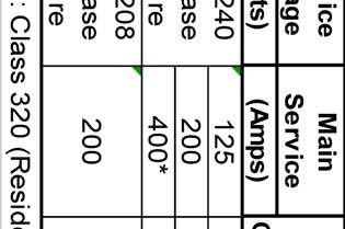
232
233
234 Service Customer s CPAU Approved Main Service Voltage Minimum Conductor Size ** (Volts) (Amps) Conduit Size AL CU 120/240 1-phase 3 wire 120/208 1-phase 3 wire / " 4/0 2/0 400* / /0 2/0 * CLASS 320 (UNDERGROUND RESIDENTIAL ONLY) ** CONDUCTOR SIZE IS PER PHASE AND A FULL SIZE NEUTRAL IS REQUIRED.
235 UTILITY SERVICE APPLICATION FOR PERMANENT SINGLE FAMILY RESIDENTIAL ELECTRIC, WATER, GAS, AND WASTEWATER SERVICE THIS FORM MUST BE FILLED OUT COMPLETELY BEFORE THIS APPLICATION CAN BE PROCESSED. Applicants requesting electric service will receive a copy of this form with City of Palo Alto Utilities (CPAU)) comments upon completion of review and approval. Project Address: Building Permit Number: Name of Applicant/ Company Address Owner Contractor Consultant City / State / Zip Phone # Name CONNECTION / INSTALLATION FEE BILLING INFORMATION Address City / State / Zip Phone # Services Requested and desired date: Project Type (check all boxes that apply) Description of Work (pertaining to Utilities) Electric Water Gas Wastewater New Construction/New Service Addition/Rebuild Total building area SQ FT Please attach a site plan and floor plans showing existing & proposed water, gas, and electric service locations; street side sanitary sewer cleanout; backflow preventers; window schedule; and elevation pages. NO FULL SET SUBMITTALS REQUIRED WATER LOADS (PER METER) GAS (PER METER) & ELECTRIC LOADS DESCRIPTION QTY DESCRIPTION LOADS (EXISTING + NEW) UNIT NUMBER OF FULL BATHROOMS WATER HEATER/TANKLESS BTUH NUMBER OF HALF BATHROOMS POOL/SPA HEATER BTUH ADDITIONAL SHOWERS TO A BATHROOM SPACE HEATING/HEAT PUMP BTUH NUMBER OF KITCHENS (1 SINK & 1 DISHWASHER) COOKING EQUIPMENT BTUH NUMBER OF LAUNDRY (1 SINK & 1 WASHING MACHINE) CLOTHES DRYER BTUH NUMBER OF HOSE BIBS FIRE LOG/FIREPLACE BTUH NUMBER OF SINKS/WETBARS (NOT KITCHEN SINK) AIR CONDITIONING kw FIRE SPRINKLER LOAD IN GPM ELECTRIC VEHICLE CHARGER kw TYPICAL GAS APPLIANCES PHOTOVOLTAIC/GENERATOR kw APPLIANCES BTUH APPLIANCES BTUH BARBEQUE 75,000 RECESSED OVEN 25,000 CLOTHES DRYER 35,000 FIREPLACE/LOG 50,000 GAS RANGE 65,000 TOP BURNER 40,000 OTHERS ELECTRIC (Include Electric Single Line Diagram of Proposed Installation) SERVICE INFORMATION Existing Requested Main Switch Size (Amps) Service Type (Check One) Number of Meters and Location (NOTE: Only one service per parcel) Overhead Underground Overhead Underground I understand and acknowledge that the City of Palo Alto Utilities will design and install its facilities based on the load and usage information I provide on this Service Application. Should this information change at a later date and require the redesign, replacement, or reinstallation of the Electric, Water, Gas, or Wastewater service(s) requested, I may incur additional costs. Initial Here Applicant Name Signature Date: Utility Service Applications involving electric utility work will be reviewed and returned to the applicant with comments. You should be sure your application is approved by Electric Engineering before proceeding with your project to avoid any delays or changes. Comments from Engineering back to the applicant will be provided on page 2 of this application and the applicant must comply with City of Palo Alto requirements before final electrical connection is performed by Utilities. SEE NEXT PAGE FOR REMARKS RETURNED FROM CPAU Utility Service Application SINGLE FAMILY Rev8 Page 1 of 2 January 7, 2015
236 FOR CPAU USE ONLY NOTES FOR APPLICANT 1. All work per CEC and CPA standards. For more details, visit 2. Payment of the final invoice must be received by the City of Palo Alto before any work will be scheduled. 3. Call electric operations ( ) for service disconnect and reconnect, if required. 4. All work must be inspected and approved by CPAU ( ) & CPA Building ( ) prior to connection by Utilities. 5. AIC rating is based on the proposed meter location. CPAU must be notified of any changes as this may affect the available short circuit current at the panel and the required AIC rating of the panel. Electric Service Information (CPAU use ONLY) Service Order Number Estimated Demand kva Transformer kva and Type Additional Sheets are Attached: Yes No Map Number Fees $ Transformer Number(s) Unless otherwise noted below * Standard Min AIC rating for panel ,000 amps Standard Min AIC rating for panel > ,300 amps * Electric Application Approved by: Phone #: Date: *Alternatively, per CPAU Engineering, the following AIC rating might be used for the requested electric panel: A Sym at V with a minimum ft. service cable length (assuming that CPAU s standard cables are used) Utility Service Application SINGLE FAMILY Rev8 Page 2 of 2 January 7, 2015
237 A GUIDE TO THE CITY OF PALO ALTO UTILITIES DEPARTMENT ELECTRIC SERVICE APPLICATION PROCESS The following procedure is intended to help you understand how your Utility Service Application for an electric service connection at your electric panel is normally processed. 1. Customer presents to BUILDING DEPARTMENT (BD) (Development Center Hamilton Ave.) a completed "UTILITY SERVICE APPLICATION" for Commercial or Residential Electric Service including all service demands and SITE and ELEVATION PLANS SHOWING THE ELECTRIC PANEL AND THE PROPOSED SERVICE LOCATION. NO FULL-SET SUBMITTALS PLEASE. BD forwards the plans and application to UTILITIES ELECTRIC ENGINEERING ("UEE") for Utilities review and approval. 2. UEE reviews plans and application. INCOMPLETE APPLICATIONS WILL NOT BE PROCESSED AND WILL BE RETURNED TO THE APPLICANT. UEE assesses the work required to furnish service to meet customer s needs, as specified in the application, within 30 BUSINESS DAYS. UEE will either send an invoice for Advance Engineering Fees, to cover cost of preparing project estimate, or for standard connection fees, for simpler projects. You must have an approved electric application on file in UEE to schedule a disconnect / reconnect request. 3. For TEMPORARY ELECTRIC SERVICE APPLICATIONS, present the TEMPORARY ELECTRIC SERVICE application to BD. Application will be approved within 1 BUSINESS DAY and an invoice will be sent to the customer. TEMPORARY SERVICE WILL BE INSTALLED BY ELECTRIC UTILITY FIELD OPERATIONS WITHIN 1 2 BUSINESS DAYS FOLLOWING RECEIPT OF FULL PAYMENT AND PANEL APPROVAL, EVIDENCED BY INSPECTION METER RELEASE TAG. Customer is responsible for contacting BD for panel inspection. 4. After plans are approved, UEE prepares the utility connection charges (if applicable) for the installation of the service and meter(s). The utility connection charges will either be attached to the Building Permit Plans or mailed to the customer. It is the customer's responsibility to be aware of this billing and to make prompt payment. Utility connection charges must be paid prior to the scheduling of any work performed by the City of Palo Alto. PERMANENT UTILITY SERVICES WILL BE INSTALLED BY ELECTRIC UTILITY FIELD OPERATIONS BETWEEN 30 AND 40 DAYS FOLLOWING RECEIPT OF FULL PAYMENT AND COMPLETION BY ANY WORK REQUIRED OF APPLICANT. 5. After the electric panel or TEMP POST/TEMP SERVICE STRUCTURE passes inspection, the BD will "yellow tag" the electric meter and send an electric meter set release tag to UTILITIES CUSTOMER SERVICE CENTER (SECOND FLOOR - CITY HALL BUILDING) which will establish an account for billing purposes. Underground Trench inspection must have a green tag before final building inspection. The Utilities Customer Service Center will check that all fees are paid before sending the electric meter installation tag to ELECTRIC OPERATIONS DISPATCH for meter installation. ELECTRIC METER(S) WILL ONLY BE INSTALLED WITH FINAL INSPECTION TAGS IN PLACE. The Customer is responsible for coordinating ALL inspections with either the Building Department AND / OR Electric Operations Dispatch. 6. YOUR UTILITY SERVICE IS NOW COMPLETE - THANK YOU FOR YOUR APPLICATION. The following directory will assist you if you have any questions throughout the installation process. ASSISTANCE - BUILDING DEPARTMENT (Development Center Hamilton Ave.) Development Center General Number BUILDING INSPECTION (Development Center Hamilton Ave.) Inspection Scheduling UTILITIES ELECTRIC ENGINEERING Contact - Electric Engineering, 1007 Elwell Ct. Office UTILITIES CUSTOMER SERVICE CENTER (2 nd Floor, City Hall) Customer Service Representatives ELECTRIC OPERATIONS DISPATCH (Municipal Service Center, MSC) For Disconnect / Reconnect and Meter Installation UNDERGROUND TRENCH INSPECTION (Municipal Service Center, MSC) Contact - Inspection Supervisor
238
239 City of Palo Alto, Utilities Electric Engineering Division OVERHEAD ELECTRIC SERVICE CHECKLIST Dear Palo Alto Resident/Contractor, The objective of this informational sheet is to help complete your project in a smooth and efficient manner, thus avoiding unnecessary delays, corrections and additional inspections. Please remember that it is your responsibility to insure that projects conform to Palo Alto Electric Service Requirements. Electric Operations Crews will not connect non-compliant services. We invite you to visit our website to consult our Electric Service Requirements Manual. Feel free to download it and print it in part or in its entirety. It is advisable to do so at the designing stage of your project. You can find us at: Any new or upgraded overhead electric service requires inspection and approval from a Building Department inspector prior to energizing. Electric Operations will connect an electric service only if it was inspected, passed and received a yellow sticker of approval. Please go over the checklist below before calling to schedule an inspection. Check each item as you verify that your project complies. Keep in mind that this is just an aid to you and in no way or manner excludes other parts of your project that are not listed here from having to meet our standards and to be in compliance with applicable requirements. Also, you ll find a sample of typical service requirements in the back of this page. Building Permit application Electric Service application Pay fees Call customer service for Account set-up & appointment for disconnecting old service See CPAU Dwg. SR-CN-O-1009 for installation details Correct placement of electric meter, electric panel and clearances with respect to other utilities. (Gas) Correct clearances between conductors and structures (see back of page) Correct lengths of wire for splicing/connecting the service (24 min. extending from weather head) Call Building inspections for Final issues a meter set tag and yellow sticker Call Utilities Customer Service to arrange for service connection For your convenience, we are including a list of telephone numbers to call when in need of additional information or to schedule inspections. All service requests and inspections are completed in the order received. There is no need to call repeatedly. Building Department (Inspections)...(650) Electric Meter Shop...(650) Dispatch...(650) Utilities Customer Service...(650) (Please make sure to have both, the Green and Yellow Stickers on your inspected service) PLEASE REMEMBER: Only qualified CPA electric personnel can enter vaults and boxes, connect, disconnect or reconnect electric services, and/or remove/install electric meters. Illegally connected services are subject to prosecution, will be disconnected, and reconnected only after ensuing investigations are completed.

240 City of Palo Alto, Utilities Electric Engineering Division UNDERGROUND ELECTRIC SERVICE CHECKLIST Dear Palo Alto Resident/Contractor, The objective of this informational sheet is to help complete your project in a smooth and efficient manner, thus avoiding unnecessary delays, corrections and additional inspections. Please remember that it is your responsibility to insure that projects conform to Palo Alto Electric Service Requirements. Electric Operations Crews will not connect non-compliant services. We invite you to visit our website to consult our Electric Service Requirements Manual. Feel free to download it and print it in part or in its entirety. It is advisable to do so at the designing stage of your project. You can find us at: Please go over each item of the checklist below to verify that your project complies. Keep in mind that this is just an aid to you and in no way or manner excludes other parts of your project that are not listed here from having to meet our standards and to be in compliance with applicable requirements. Also, you ll find a sample of typical service requirements in the back of this page. Electric Operations Crews will connect an electric service only after it was inspected and received: a green sticker of approval from underground inspection AND a yellow sticker of approval from Building inspection. Building Permit application Electric Service application Pay fees Call Underground Service Alert (USA ) before you dig Call Customer Service for Account set-up / appt for disconnect old service See CPAU Dwg SR-CN-U-1010 for installation details Contact Electric Underground Inspector: 48 hrs+ before digging to confirm routing Correct placement of electric meter, electric panel and correct clearances with respect to other utilities (Gas) a. No more than three 90 degree bends, (270 degrees total) between pull boxes in a conduit run b. Trenches for residential services: 24 cover in non-traffic areas. 30 cover in traffic areas c. For conduit below ground, use schedule 40 or DB-120 PVC only Conduit installation must be approved by CPA Underground Inspector prior to backfilling for green sticker. Pulling of appropriate size mandrel throughout the entire conduit system (No blockage test) Pulling of conductors from pull box to service. (Slack at the box= 2 X box length) Call Building inspections for Final issues a meter set tag and yellow sticker Call Utilities Customer Service to arrange service connection Telephone numbers to call when in need of additional information or to schedule inspections: (All service requests and inspections are completed in the order received. There is no need to call repeatedly.) Building Department (Inspections)...(650) Utility Underground Inspector...(650) Electric Meter Shop...(650) Dispatch...(650) Utilities Customer Service...(650) (Please make sure to have both, the Green and Yellow Stickers on your inspected service) PLEASE REMEMBER: Only qualified CPA electric personnel can enter vaults and boxes, connect, disconnect or reconnect electric services, and/or remove/install electric meters. Illegally connected services are subject to prosecution, will be disconnected, and reconnected only after ensuing investigations are completed.
241 City of Palo Alto Summary of Installation Requirements Residential Electric Service This document contains a summary of the City of Palo Alto Utilities (CPAU) requirements. The Applicant has the responsibility to ensure that their final design and installation complies with ALL City of Palo Alto standards. CPAU standards are detailed in the Electric Service Requirements manual, available on the internet at: SUMMARY OF GENERAL REQUIREMENTS The Applicant (includes customer, customer s contractor, customer s consultant, developer, or others working on behalf the owner) is responsible for ALL costs associated with the provision of electric service for their project, excluding the material cost of the transformer and electric meter. Applicant must provide a completed Utility Service Application and site and elevation plan submittal. The site plan will include at a minimum, an outline of the property lines showing streets; an outline of buildings on the property; a proposed meter location; location of pools or spas; identification of any other significant features on the property that will impact either overhead or underground service wires; and a description of work. The elevation shall show the location of the meter an its relation to other utility or building equipment/windows. FULL-SET SUBMITTALS NOT REQUIRED. If a project requires preparation of a project design and estimate, CPAU will charge the Applicant a non-refundable Advance Engineering fee prior to the start of engineering design, plan review, and development of the cost estimate. To initiate engineering design, the Applicant must submit payment at Revenue Collections, 1 st Floor, City Hall, City of Palo Alto. If the project is cancelled by the Applicant, the fee is forfeited. Service upgrades requiring 400 Amperes or larger may require a padmount transformer and Easement grant. SUMMARY OF TECHNICAL REQUIREMENTS 1. The Applicant will provide and install service cables and conduit from main panel to the CPAU utility pull box or service point (as determined by CPAU). 2. If underground service cables are connecting to an overhead secondary line, the Applicant will install a box at the base of the pole and a 4 inch riser conduit from the box to the pole. 3. The meter location is subject to CPAU s approval. 4. The Property title-holder will retain ownership of underground service lateral conduits and substructures and are fully responsible for any maintenance or replacement, as necessary. 5. The owner/developer will provide, at no charge to CPAU, easements and access to all electrical utility facilities that are located on private property. At a minimum, a draft easement shall be submitted before any service is energized. 6. Sockets with Test Bypass Facilities are required for panel greater than 200A and are not allowed for panels rated 200A or less.
242 City of Palo Alto Summary of Installation Requirements Residential Electric Service Underground Service from an Underground Electric System Applicant will install as required: Service box as required by CPAU Panel, meter socket enclosure, service riser Conduit from panel to utility service box Service cable from panel to utility service point Property title-holder will own and maintain: Panel, meter socket, service riser and conduit CPAU will install as required: Transformer Meter Connectors at utility service point CPAU will own and maintain: Meter, service cable, transformer, service box Underground Service from an Overhead Electric System Applicant will install as required: Service box at the base of the CPAU pole Panel, meter socket enclosure, service riser Conduit from panel to utility service box, 4 riser stub, and enough cable to reach from the meter to the secondary level on the service pole via the service box, including excess cable in the box equal to twice the length of the box. Property title-holder will own and maintain: Panel, meter socket, service riser and conduit CPAU will install as required: Transformer Customer provided cable up CPAU utility pole and cover Meter Connectors at utility service point CPAU will own and maintain: Meter, service cable, transformer, service box Overhead Service from an Overhead Electric System Applicant/Property title-holder will install, own, and maintain, as required: Panel and meter socket enclosure Service Entrance riser and cable Weatherhead and insulated service drop attachment CPAU will install as required: Transformer Service drop wire (maximum length 100 feet) Meter Connectors at weather head
243 City of Palo Alto Summary of Installation Requirements Frequently Asked Questions Other than the work I am proposing for my building, is there anything else I am required to install? You are responsible for installing all substructures (boxes, conduits, etc.) and service cable as determined to be required by CPAU to provide electric service. Can you recommend a Electrical Contractor? Unfortunately, CPAU is unable to recommend one private contractor over another. Where do I submit by Utility Service Application and plans? Utilities has a representative at the City of Palo Alto Development Center, 285 Hamilton Avenue, who can accept your application or answer questions about your project or the process. If necessary, a time can be set up to meet with staff in Engineering to discuss details of your project. Is Electric Engineering located at the Development Center downtown? No, Electric Engineering is located at 1007 Elwell Court off of East Bayshore Road near San Antonio exit off Highway 101. Our hours are Monday through Friday, 9:00 am to 4:00 pm. I am preparing to submit plans for a permit on a new Commercial Development, but before I do, I would like to discuss what can be expected to provide electric service? CPAU would be more than willing to meet to do a preliminary review of your electric service needs. We can layout your service options and determine a service location relevant to the available source. We can provide a clear understanding of the utilities standards and policies regarding your service request. A Utilities representative is available at the Development Center for consultation. I now live in the main house and I have a rental cottage located at the rear of my property, I would like to have a separate meter for the cottage, can that be done? Our rules only allow one service per lot. To meter the cottage you will need to hire a licensed electrician to change out your existing single meter panel with a dual meter panel. You will also need to contact our customer service department to set up an account for the new meter. I have lines installed on poles that run behind my house. underground? Can I get them placed You would be responsible for all costs associated with this work. This includes, but is not limited to, the cost for undergrounding the lines for all utilities (electric, phone, CATV) on the pole, undergrounding the services of any customer affected with this request, and the cost of any easements, permits, and inspections, required for this work.
244

245
246 Service Customer s CPAU Approved Main Service Voltage Minimum Conductor Size ** (Volts) (Amps) Conduit Size AL CU 120/240 1-phase 3 wire 120/208 1-phase 3 wire / " 4/0 2/0 400* / /0 2/0 * CLASS 320 (UNDERGROUND RESIDENTIAL ONLY) ** CONDUCTOR SIZE IS PER PHASE AND A FULL SIZE NEUTRAL IS REQUIRED.
247
248 NOTES 1. REQUIRED CLEARANCES APPLY TO PUBLIC, COMMERCIALLY OPERATED, AND RESIDENTIAL POOLS. DIMENSION A. VERTICAL CLEARANCE FROM HIGHEST WATER LEVEL: 22.5 FEET B. RADIAL CLEARANCE FROM TOP EDGE OF POOL WALL 22.5 FEET C. VERTICAL CLEARANCE FROM DIVING BOARD OR PLATFORM THAT IS OVER THE WATER SURFACE OF THE POOL: D. VERTICAL CLEARANCE ABOVE DIVING BOARD OR PLATFORM THAT IS NOT OVER THE WATER SURFACE OF THE POOL: 14.5 FEET 14.5 FEET 2. HORIZONTAL LIMIT OF CLEARANCES ARE TO THE OUTER EDGE OF ANY ITEMS IDENTIFIED IN ITEMS A TO D, BUT NO LESS THAN 10 FEET OUT FROM THE INSIDE WALL OF POOL. 3. INSTALLATION OF SERVICE DROPS ABOVE SWIMMING POOLS, HOT TUBS, AND SPAS SHALL BE AVOIDED. 4. IF IN THE OPINION OF CITY OF PALO ALTO UTILITIES ENGINEERING AND OPERATIONS PERSONNEL AN OVERHEAD SERVICE INSTALLATION DESIGNED TO MEET THE STIPULATED CLEARANCE REQUIREMENTS CREATES AN UNSAFE WORKING CONDITION FOR UTILITY WORKERS, THE SERVICE WILL BE REQUIRED TO BE UNDERGROUND. REFERENCE: CALIFORNIA ELECTRICAL CODE, ARTICLE 680.8
249
250 UTILITY SERVICE APPLICATION PERMANENT COMMERCIAL/MULTI-FAMILY ELECTRIC, WATER, GAS, AND WASTEWATER FACILITIES INSTALLATION THIS FORM MUST BE FILLED OUT COMPLETELY BEFORE THIS APPLICATION CAN BE PROCESSED. Upon Completion of review and approval a copy of this form will be sent back to applicants requesting Electric Service. Building Department Permit Application Number: Utilities Department Permit Application Number: Project Address: Date: Name of Applicant / Company Phone #: Address City / State Zip CONNECTION FEE BILLING INFORMATION Name Phone: Address City / State Zip Service Type Requested: Electric Water Gas Wastewater Desired Service Date: Project Status Planning Bidding Construction (Depending on Utility Service Requested, Complete Appropriate Portions of this Application) 4 Project Type (check all boxes that apply) New Construction/New Service ** Addition ** Remodel What will be the total building area upon completion? SQ FT Service Upgrade Service Relocation ** Spa or Pool ** Other (explain in Description of Work) Brief Description of Work ** Please attach a site plan showing the property lines including elevations, a window schedule, site improvements with existing & proposed service locations, AND a front view photograph of the gas and electric meter locations existing & proposed. Photograph MUST contain a ground to roof line view with meters at the center of the picture. photograph to utilities.engineering@cityofpaloalto.org NO FULL SET SUBMITTALS.. Gas/Electric Load Information (INDICATE PEAK OR MAXIMUM RATES OF USE OR FLOW) Separate load information is required for each gas meter requested. Attach adequate Electric Load information verifying National Electric Code Article 220 (Branch Circuit and Feeder Calculations) requirements are met. Description Gas Electric Existing New (Additional) Total (Existing + New) Units (circle one) SPACE HEATING BTUH kw kva HVAC (1 Phase electric) HVAC (3 Phase electric) kw kva WATER HEATING BTUH kw kva COOKING EQUIPMENT BTUH kw kva CLOTHES DRYER BTUH kw kva FIRE LOG LIGHTER POOL/SPA HEATER BTUH kw kva POOL/SPA PUMP LIGHTING kw kva RECEPTACLE, OTHER kw kva PROCESS POWER kw kva ELEVATORS kw kva LARGEST MOTOR kw kva OTHER MOTORS (1 PH) kw kva OTHER MOTORS (3 PH) kw kva BTUH: BTU (British Thermal Unit) PER HOUR kw: kilowatts (=1000 Watts) kva: kilovoltamps (=1000 Voltamps) hp: Horsepower Continued on page 2 Utility Service Application COMM_MULTI-FAMILY Page 1 of 2 August 24, 2011 BTUH BTUH hp
251 Description Gas Electric Existing New (Additional) Total (Existing + New) PHOTOVOLTAIC SYSTEM kw kva ELECTRIC VEHICLE CHARGING SYSTEM (Load per Charging Station) Number of Charging stations: Number of electric vehicles: per charger kw kva Units (circle one) OTHER BTUH kw kva hp OTHER BTUH kw kva hp BTUH: BTU (British Thermal Unit) PER HOUR kw: kilowatts (=1000 Watts) kva: kilovoltamps (=1000 Voltamps) hp: Horsepower Water WATER LOADS: SEE WATER CUSTOMER DEMAND DATA TABLE FOR CALCULATING FIXTURE UNITS AND GALLONS PER MINUTE. Complete a separate LOAD CALCULATION SHEET for each domestic water meter, fill in all applicable areas below, and submit completed Calculation Sheets with Service Application. EXISTING NEW (ADDITIONAL) TOTAL (EXISTING + NEW) DOMESTIC USE F.U. F.U. G.P.M. FIRE SPRINKLER G.P.M. G.P.M. G.P.M. IRRIGATION USE MAX VALVE G.P.M. G.P.M. G.P.M. F.U.: Fixture Units G.P.M.: Gallons per Minute CPAU USE ONLY Wastewater WASTEWATER LOADS: REFER TO SECTION 2730 IN THE CURRENT UTILITY STANDARDS FOR WASTEWATER DESIGN STANDARDS. Complete LOAD CALCULATION SHEET, fill in all applicable areas below, and submit completed Calculation Sheet with Service Application. EXISTING FIXTURE UNITS NEW FIXTURE UNITS EXISTING # Dwelling Units/S.F. NEW # Dwelling Units/S.F. TOTAL (EXISTING + NEW) MULTI-FAMILY F.U. F.U. D.U. D.U. D.U. COMMERCIAL F.U. F.U. S.F. S.F. S.F. RESEARCH/OFFICE F.U. F.U. S.F. S.F. S.F. F.U.: Fixture Units D.U.: Dwelling Units S.F.: Square-Feet BACKFLOW PREVENTER REQUIREMENTS To comply with requirements of the California Administrative Code, Title 17, Sections 7583 through 7605 inclusive and City of Palo Alto Utility Rule and Regulation 21; the City of Palo Alto requires that all commercial or multifamily water connections have an RP backflow preventer installed on the owner s property directly behind the water meter within 5 feet of the property line. Show the location of all RP backflow preventers on the plans. An approved reduced pressure principle assembly (RPPA backflow preventer device) is required for all existing and new irrigation or domestic water connections from Palo Alto Utilities. An approved reduced pressure detector assembly is required for the existing or new fire water connections. ELECTRIC (INCLUDE ELECTRIC SINGLE LINE DIAGRAM OF PROPOSED INSTALLATION) SERVICE INFORMATION Existing Requested Service Voltage Main Switch Size (Amps) Type & Number of Meters Electric Service Information (CPAU Use ONLY) Service Order Number Estimated Demand kva Transformer kva and Type Remarks Map Number Transformer Number(s) Minimum AIC rating of Electric Panel Fees $,000 A Sym at V for requested service: ALL work per NEC and CPA Standards. Additional fees may apply after permit approval Electric service panel must meet the AIC rating indicated above for the requested service voltage. Service Panels 400 A or greater submit factory drawings for approval. Otherwise catalog cutsheets are acceptable. Only socket type meters are allowed. Call Electric Operations ( ) for service Disconnect and Reconnect, if required. All work must be inspected and approved by the CPAU Inspector ( ) and CPA Building Department ( ) prior to final connection by Utilities. Approved by: Phone #: Date: Additional Sheets are Attached: Yes No Utility Service Application COMM_MULTI-FAMILY Page 2 of 2 August 24, 2011
252 A GUIDE TO THE CITY OF PALO ALTO UTILITIES DEPARTMENT ELECTRIC SERVICE APPLICATION PROCESS The following procedure is intended to help you understand how your Utility Service Application for an electric service connection at your electric panel is normally processed. 1. Customer presents to BUILDING DEPARTMENT (BD) (Development Center Hamilton Ave.) a completed "UTILITY SERVICE APPLICATION" for Commercial or Residential Electric Service including all service demands and SITE and ELEVATION PLANS SHOWING THE ELECTRIC PANEL AND THE PROPOSED SERVICE LOCATION. NO FULL-SET SUBMITTALS PLEASE. BD forwards the plans and application to UTILITIES ELECTRIC ENGINEERING ("UEE") for Utilities review and approval. 2. UEE reviews plans and application. INCOMPLETE APPLICATIONS WILL NOT BE PROCESSED AND WILL BE RETURNED TO THE APPLICANT. UEE assesses the work required to furnish service to meet customer s needs, as specified in the application, within 30 BUSINESS DAYS. UEE will either send an invoice for Advance Engineering Fees, to cover cost of preparing project estimate, or for standard connection fees, for simpler projects. You must have an approved electric application on file in UEE to schedule a disconnect / reconnect request. 3. For TEMPORARY ELECTRIC SERVICE APPLICATIONS, present the TEMPORARY ELECTRIC SERVICE application to BD. Application will be approved within 1 BUSINESS DAY and an invoice will be sent to the customer. TEMPORARY SERVICE WILL BE INSTALLED BY ELECTRIC UTILITY FIELD OPERATIONS WITHIN 1 2 BUSINESS DAYS FOLLOWING RECEIPT OF FULL PAYMENT AND PANEL APPROVAL, EVIDENCED BY INSPECTION METER RELEASE TAG. Customer is responsible for contacting BD for panel inspection. 4. After plans are approved, UEE prepares the utility connection charges (if applicable) for the installation of the service and meter(s). The utility connection charges will either be attached to the Building Permit Plans or mailed to the customer. It is the customer's responsibility to be aware of this billing and to make prompt payment. Utility connection charges must be paid prior to the scheduling of any work performed by the City of Palo Alto. PERMANENT UTILITY SERVICES WILL BE INSTALLED BY ELECTRIC UTILITY FIELD OPERATIONS BETWEEN 30 AND 40 DAYS FOLLOWING RECEIPT OF FULL PAYMENT AND COMPLETION BY ANY WORK REQUIRED OF APPLICANT. 5. After the electric panel or TEMP POST/TEMP SERVICE STRUCTURE passes inspection, the BD will "yellow tag" the electric meter and send an electric meter set release tag to UTILITIES CUSTOMER SERVICE CENTER (SECOND FLOOR - CITY HALL BUILDING) which will establish an account for billing purposes. Underground Trench inspection must have a green tag before final building inspection. The Utilities Customer Service Center will check that all fees are paid before sending the electric meter installation tag to ELECTRIC OPERATIONS DISPATCH for meter installation. ELECTRIC METER(S) WILL ONLY BE INSTALLED WITH FINAL INSPECTION TAGS IN PLACE. The Customer is responsible for coordinating ALL inspections with either the Building Department AND / OR Electric Operations Dispatch. 6. YOUR UTILITY SERVICE IS NOW COMPLETE - THANK YOU FOR YOUR APPLICATION. The following directory will assist you if you have any questions throughout the installation process. ASSISTANCE - BUILDING DEPARTMENT (Development Center Hamilton Ave.) Development Center General Number BUILDING INSPECTION (Development Center Hamilton Ave.) Inspection Scheduling UTILITIES ELECTRIC ENGINEERING Contact - Electric Engineering, 1007 Elwell Ct. Office UTILITIES CUSTOMER SERVICE CENTER (2 nd Floor, City Hall) Customer Service Representatives ELECTRIC OPERATIONS DISPATCH (Municipal Service Center, MSC) For Disconnect / Reconnect and Meter Installation UNDERGROUND TRENCH INSPECTION (Municipal Service Center, MSC) Contact - Inspection Supervisor
253
254 City of Palo Alto Summary of Installation Requirements Commercial or Multifamily Electric Service This document contains a summary of the City of Palo Alto Utilities (CPAU) requirements for the project. The Applicant has the responsibility to ensure that their final design and installation complies with ALL City of Palo Alto standards. CPAU standards are detailed in the Electric Service Requirements manual, available on the internet at: SUMMARY OF GENERAL REQUIREMENTS The Applicant (includes customer, customer s contractor, customer s consultant, developer, or others working on behalf the owner) is responsible ALL costs associated with the provision of electric service as required for their project, excluding the material cost of the transformer and electric meter. Applicant must provide a completed Utility Service Application and site plan submittal. The site plan will include at a minimum, an outline of the property lines showing streets; an outline of buildings on the property; a proposed meter location; location of pools or spas; identification of any other significant features on the property that will impact either overhead or underground service wires; and a description of work. FULL-SET SUBMITTALS NOT REQUIRED. CPAU may charge the Applicant a non-refundable Advance Engineering Fee prior to the start of engineering design, plan review, and development of the cost estimate. To initiate engineering design, the Applicant must submit payment at Revenue Collections, 1 st Floor, City Hall, City of Palo Alto. If the project is cancelled by the Applicant, the fee is forfeited. CPAU will only provide a maximum service size of 1,600 Amperes at 208Y/120V, three-phase, 4- wire. Any service larger than 1,600 Amperes will be served at 480 Volts. Primary metering is also available. Service upgrades requiring 400 Amperes or larger will be underground and will require a padmount transformer and Easement grant. CPAU provides Fiber Optic service to City of Palo Alto customers. Please contact CPAU Fiber Optic Marketing Coordinator at (650) for inquiries. 7/18/2016
255 City of Palo Alto Summary of Installation Requirements Commercial or Multifamily Electric Service SUMMARY OF TECHNICAL REQUIREMENTS Applicant is responsible for ensuring that final installations meet all City of Palo Alto requirements. Every project is different, contact CPAU Engineering for specific design requirements for your project. 1. To provide electric service to the proposed development, the following may be required: Underground primary distribution line extension Underground secondary line extension Transformer installation or replacement Other primary equipment or replacement 2. Applicant shall provide all necessary underground substructures which may include the following: Transformer Pad(s) Guard Posts Loadbreak Junction Pad Primary Vault(s) Primary Pull Box(es) Primary Feeder Conduits Secondary Pull Box(es) Secondary Conduits Service Conduit & Cable 3. CPAU will furnish and install (at customer s expense) all required: Switch(es) Transformer(s) Primary cables Secondary cables Overhead Service Wire 4. The Applicant shall furnish and install service cables and conduit from each building to the CPAU utility pull box or service point (as determined by CPAU). 5. The Applicant shall furnish and install EUSERC compliant service equipment for each building. Meter locations shall be subject to CPAU s approval. 6. All 480 Volt services and all other services 400 Amperes or larger shall have a single main disconnect. Service equipment shop drawing submittal will be required for CPAU approval BEFORE equipment is manufactured. A copy of the same drawing shall be submitted to the City s Development Services Center for approval by the Building Inspector. 7. CPAU will take ownership and will be responsible for maintaining the new underground primary and secondary distribution systems, and service cables. 8. The Property title-holder will retain ownership of service conduits and substructures and are fully responsible for any maintenance or replacement, as necessary. 9. The owner/developer shall provide, at no charge to CPAU, easements and access to all electrical utility facilities that are in the private property. At a minimum, a draft easement shall be submitted before any service can be energized. 10. Sockets with Test Bypass Facilities are required for all commercial and multifamily services/panel. 7/18/2016
256 City of Palo Alto Summary of Service Equipment Requirements Commercial or Multifamily Electric Service THIS SHEET OUTLINES SOME OF THE REQUIREMENTS FOR SERVICES 400 AMPS OR GREATER. SUMMARY OF SERVICE EQUIPMENT REQUIREMENTS Applicant is responsible for ensuring that final installations meet all City of Palo Alto and City of Palo Alto Utilities (CPAU) requirements. CPAU will furnish and install the necessary metering CT s, PT s, and test switch. For service equipment approval, applicant s equipment must comply with all CPAU and City of Palo Alto requirements including those summarized below. All service equipment will have provisions for sealing the meter per EUSERC requirements. Applicant shall provide service equipment shop drawings to CPAU for review, prior to manufacture, to avoid delays due to field modifications. Drawings should be sent to CPAU Electrical Engineering, 1007 Elwell Court, Palo Alto, The phone number for CPAU Electrical Engineering is Final service equipment submittals must be provided to, and approved by CPAU prior to installation. Installation shall be inspected and approved by City of Palo Alto Building Department and CPAU before connection to CPAU s electrical system. The following information (where applicable) shall be shown on submittals: 1. Service Equipment: Indoor (NEMA 1 or better) or Outdoor (NEMA 3R or better) 2. Service Rating: Amperes Volts Phase Wires 3. Main Disconnect: Circuit Breaker or Fused Switch 4. Minimum Interrupting or Short Circuit Rating of Panel: A, RMS : V L-L 5. CT Compartment (per EUSERC #320 or #322, whichever is applicable) 6. Meter Plate (per EUSERC #332) 7. Pull Section (per EUSERC #345) 8. Line Termination (per EUSERC #347) 9. Residential 400A (Class 320), 120/240 V meter panel (per EUSERC #302B) 10. Factory-installed bolt-type test by-pass/disconnect block (for self contained meters only) 11. CPAU installs only socket type meters. Meter socket require the following number of jaws: 120/240 V, single phase, 3 wire service 4 120/208V, single phase, 3 wire service 5 (with jaw at 9 o-clock position) 120/208 V, three phase, 4 wire service 7 or 13 (7 up to 200A, 13 greater than 200A) 277/480 V, three phase, 4 wire service 7 or 13 (7 up to 200A, 13 greater than 200A) 12. Space for installing potential transformers shall be provided inside the electric panel per CPAU Drawing # SR-MT-M-1019, as required. NOTE: Please contact the Electric Meter Shop, at (650) as soon as the equipment arrives at the job site to schedule the inspection of the equipment and installation of CPAU-furnished instrument transformers and other metering devices. The service equipment will also have to be inspected and approved by the City of Palo Alto s Building Department Electrical Inspector, (650) , before it can be energized. 7/18/2016
257 City of Palo Alto Frequently Asked Questions Commercial or Multifamily Electric Service How long will it take to review our submittal? Providing all the information is available at the time of submittal, you can expect a 10 business days turn around for initial response. What kind of costs can I expect for an electric service? An estimated service order inclusive of labor and materials costs to provide the requested service will be required to determine the cost of providing electric service. The Applicant is responsible for ALL costs associated with the provision of electric service as required for their project, excluding the material cost of the utility transformer, switches, and electric meter. Other than the work I am proposing for my building, is there anything else I am required to install? You are responsible for installing all substructures (boxes, conduits, etc.) and service cable as determined to be required by CPAU to provide electric service. Where do I submit by Utility Service Application and plans? Utilities has a representative at the City of Palo Alto Development Center, 285 Hamilton Avenue, who can accept your application or answer questions about your project or the process. If necessary, a time can be set up to meet with staff in Engineering to discuss details of your project. Prior to submitting plans for permit on a new Commercial Development may I discuss what can be expected to provide electric service? CPAU would be more than willing to meet to do a preliminary review of your electric service needs. We can layout your service options and determine a service location relevant to the available source. We can provide a clear understanding of the utilities standards and policies regarding your service request. A Utilities representative is available at the Development Center for consultation. Is Electric Engineering located at the Development Center downtown? No, Utilities Engineering is located at 1007 Elwell Court off of East Bayshore Road near San Antonio exit off Highway 101. Our hours are Monday through Friday, 9:00am to 4:00pm. How do I get temporary power for construction? Complete an Electric Application for Temporary Commercial Electric service and submit to Utilities Engineering. This is a separate application form in addition to the Permanent Electric Application. 7/18/2016

258 Utilities Department Electric Vehicle Supply Equipment (EVSE) Information THIS DOCUMENT PROVIDES INFORMATION FOR NEW EVSE INSTALLATIONS. IF THE ELECTRIC SERVICE MAIN PANEL WILL BE UPGRADED, PLEASE COMPLETE THE UTILITY SERVICE APPLICATION AND SUBMIT WITH THIS DOCUMENT. Installing an Electric Vehicle Supply Equipment (EVSE) will require changes to building wiring and may also require upgrading the electric service main panel to meet the needs of this specialized equipment. Before installing an EVSE and associated infrastructure, talk to your EV manufacturer for information about what you need to charge your vehicle and what regulatory requirements there might be. When installing your EVSE, be sure to use a licensed electrical contractor whose license is current for electrical work. The contractor should also follow the guidelines of the manufacturer and the requirements of City of Palo Alto Building Codes. A permit from the City is required before installing EVSE. Submit building and electrical plans for the planned installation with your permit application to the City of Palo Alto Development Center. Why is the Electric Utility concerned about your EVSE installation? Though an individual EVSE may have a negligible impact on the utility electric system, the combined effect of several chargers in the same service area could result in overloading the utility lines and transformers. It is crucial that the City of Palo Alto Utilities is notified of any EVSE installations to ensure that the utility electrical system remains adequately sized to serve our customers and maintain high levels of service reliability. The Utilities department needs information on location (address), number of EVSE being installed, EVSE current rating, and number of electric vehicles. UTILITIES REVIEW AND APPROVAL IS REQUIRED BEFORE THE BUILDING DEPARTMENT WILL ISSUE PERMITS FOR INSTALLATION OF EVSE RATED GREATER THAN 40 AMP, OR THAT REQUIRES AN OVERCURRENT PROTECTION DEVICE (CIRCUIT BREAKER) GREATER THAN 50 AMP. FAILURE TO DO SO COULD DAMAGE UTILITY SYSTEM FACILITIES, WITH THE OFFENDER RESPONSIBLE FOR THE COST OF REPAIRS. Please provide the following information and submit with copies of any documentation from the charger manufacturer (cut sheets, installation instructions, specifications, etc.). Project Address: Building Department Permit # Contact Person: Phone: Number of EVSE being installed: Number of Electric Vehicles: EVSE Rating(s): Quantity Voltage (V) Current (A) Power (kva) CPAU Engineering Review (required for EVSE > 40 Amp (50 Amp circuit breaker) - A copy of this approved form must be submitted to the City of Palo Alto Building department before a permit will be issued Approved By: Date:
RESIDENTIAL UNDERGROUND AND OVERHEAD SERVICE REQUIREMENTS SECTION II RESIDENTIAL UNDERGROUND AND OVERHEAD SERVICE REQUIREMENTS
 SECTION II This section discusses the City of Palo Alto's requirements for establishing electric service to new or upgraded residential installations. The same requirements apply to both underground and
RESIDENTIAL SUBDIVISION SERVICE REQUIREMENTS SECTION VI RESIDENTIAL SUBDIVISION SERVICE REQUIREMENTS
 SECTION VI SERVICE REQUIREMENTS This section discusses the requirements for establishing electric service to new residential subdivisions in Palo Alto. Subdivisions are normally constructed on dedicated
COMMERCIAL QUICK REFERENCE
 COMMERCIAL QUICK REFERENCE PROVO CITY POWER STANDARDS ELECTRICAL ENGINEERING UPDATED: 2016 SPECIFICATIONS SUBJECT TO CHANGE WITHOUT NOTIFICATION. 18" MIN. OF TAIL. (NEUTRAL CONDUCTOR MUST BE WHITE OR
10 Commercial, Industrial, Agricultural Services
 10 Commercial, Industrial, Agricultural Services This section describes the Power Company requirements for commercial, industrial, and agricultural services. This section covers single phase and three
Metering and Service Installation:
 Table of Contents 1. Metering Installation Requirements, General... 1 2. Type of Service... 2 3. Definitions... 2 4. Who Provides Metering Equipment?... 2 5. Establishment of Service... 2 6. Meter Access...
For Conduit Inspections
 Underground Conduit Standards - Table of Content 5/8/2017 Section S22 Underground Conduit Standard Index: Description: 00 Table of Content 01 General Notes 02 Definition of Terms 03 Primary Riser Conduit
Electric Service Requirements
 Electric Service Requirements Section V Commercial Industrial July 2007 ENGINEERING SPECIFICATION 620 S Street, P.O. Box 5830, Sacramento, CA 95852-830 The Power To Do More ṢM SM A registered service mark
7. Residential Single-Family and Duplex Buildings (Dwellings)
") Sin g le -F a mily a n d Du p le x Bu ild in g s 2016 Electric Service Requirements, 2 nd Edition Section 7 Section 7 Residential Single-Family and Duplex Buildings (Dwellings) Directory Page 7.1 General
Sin g le -F a mily a n d Du p le x Bu ild in g s 2016 Electric Service Requirements, 2 nd Edition Section 7 Section 7 Residential Single-Family and Duplex Buildings (Dwellings) Directory Page 7.1 General
9. Non-Residential Services (Commercial, Industrial, and Agricultural)
") Section 9 2016 Electric Service Requirements, 3rd Edition Section 9 Non-Residential Services Directory Page 9.1 General Requirements 68 9.2 Direct-Connect Metering, Single Installations 69 9.3 Direct-Connect
Section 9 2016 Electric Service Requirements, 3rd Edition Section 9 Non-Residential Services Directory Page 9.1 General Requirements 68 9.2 Direct-Connect Metering, Single Installations 69 9.3 Direct-Connect
PUBLIC UTILITY DISTRICT NO. 1 OF LEWIS COUNTY METERING SPECIFICATIONS
 PUBLIC UTILITY DISTRICT NO. 1 OF LEWIS COUNTY METERING SPECIFICATIONS 1. General Metering Requirements a. Interpretation The District s metering requirements shall not be interpreted to conflict with the
7 Single Family Service
 7 Single Family Service 7. General The location of the service entrance on the Customer s premises is an important consideration. For clearance and location information see section 5 (Clearances). Consult
Section 6 Electric Metering: Residential
 Section 6 Electric Metering: Residential 6.1. Scope This section provides specific information for residential metering that is not covered by the basic requirements in Section 5, Electric Metering: General.
SECTION 300 OVERHEAD SERVICE
 SECTION 300 OVERHEAD SERVICE 300.01 General Company provides, installs, and maintains service drop to point of delivery approved by Company. Customer provides point of attachment which is acceptable to
Indianapolis Power & Light Company
 Indianapolis Power & Light Company Electric Service and Meter Manual The Electric Service & Meter Manual is not copyrighted and permission is hereby given to reproduce this document. However, the Indianapolis
Associated equipment As related to metering equipment: such as the current transformers, CT wiring and test switches.
 APPENDIX Glossary Approval Acceptable to the authority having jurisdiction. Assessor s Parcel Number (APN) Identifying number assigned by the county assessor s office to each taxable building lot in the
Commercial Electric Service Handbook
 Commercial Electric Service Handbook January 2011 CONTACTS Clark Public Utilities: Website........................................... www.clarkpublicutilities.com Construction Services department (To initiate
SPECIFICATIONS FOR RESIDENTIAL CONSTRUCTION
 Roseville Electric SPECIFICATIONS FOR RESIDENTIAL CONSTRUCTION REVISED 04/25/18 Specifications for Residential Construction Revision List REVISION Date Page No. Description 03/20/00 6.1-6.2 Added Armorcast
TEMPORARY ELECTRICAL SERVICE
 ENERGY SERVICES ENGINEERING 840 Northgate Drive Telephone (509) 942-7403 Fax (509) 942-7405 P.O. Box 190 Richland, WA 99352 www.ci.richland.wa.us/energyservices TEMPORARY ELECTRICAL SERVICE A. INTRODUCTION
AGRICULTURAL UNDERGROUND SERVICE 500 HP OR LESS
 Prepared by: ABB1 AGRICULTURAL UNDERGROUND SERVICE 500 HP OR LESS 05619 Asset Type: Electric Metering Function: Design and Construction Issued by: Lisseth Villareal (LDV2) Date: 07-31-15 Rev. #10: This
Requirements for Secondary Voltage Revenue Metering (750 V and less)
") Requirements for Secondary Voltage Revenue Metering (750 V and less) To view the latest revision of this document go to: http://www.bchydro.com/ext/metering/ January 28, 2010 Copyright 2008 by BC Hydro.
Requirements for Secondary Voltage Revenue Metering (750 V and less) To view the latest revision of this document go to: http://www.bchydro.com/ext/metering/ January 28, 2010 Copyright 2008 by BC Hydro.
PERMANENT RESIDENTIAL UNDERGROUND SERVICE
 CITY OF RICHLAND ENERGY SERVICES DEPARTMENT 505 Swift Boulevard, MS-21 Richland, WA 99352 Telephone (509) 942-7403 Fax (509) 942-7405 PERMANENT RESIDENTIAL UNDERGROUND SERVICE A. INTRODUCTION This guide
NEW SERVICE HANDBOOK COMMERCIAL & IRRIGATION SUPPLEMENT
 NEW SERVICE HANDBOOK COMMERCIAL & IRRIGATION SUPPLEMENT Meter Installations There are three basic ways to measure electricity consumption: Small and medium services are metered directly using direct connect
UNDERGROUND SERVICE. Items to consider. There will be charges from ComEd if you convert from overhead to underground service.
 UNDERGROUND SERVCE tems to consider f your trenching route has to be dug by hand, or if a cable must be installed under a paved surface, additional charges apply. f your service cable has to be moved later
STOUGHTON UTILITIES ELECTRIC SERVICE RULES AND INFORMATION
 CHAPTER 1 - GENERAL INFORMATION 100. Purpose 101. Codes and rules 102. Continuity of service 103. Frequency, Voltage, and Amperage Limitations 104. High voltages 105. Unusual capacity requirements 106.
AMENDMENT ELECTRIC SERVICE MANUAL 2014
 AMENDMENT (Pages 20,43,50,72,74,,76,78,83,86,99) ELECTRIC SERVICE MANUAL 2014 Effective April 1, 2015 18-7 6.0 SERVICE AND SERVICE ENTRANCES (General), Continued Conductor Sizing It is recommended that
SERVICE ATTACHMENT ON A BUILDING WITH BUS DUCT SERVICE ENTRANCE AND INDOOR METERING
 SERVICE ATTACHMENT ON A BUILDING WITH BUS DUCT SERVICE ENTRANCE AND INDOOR METERING Obtain acceptance and specific details from the local Company office. 1. Service entrance duct (see Note 1). Company
Clark Public Utilities Commercial Electric Service Handbook. This page left blank intentionally.
 This page left blank intentionally. 38 Chapter 4: Commercial Metering / January 2011 APPENDIX Glossary Approval Acceptable to the authority having jurisdiction. Associated equipment As related to metering
Pentahead bolts See note 2. Conduit run as specified. Company facility. Refer to drawing SS8.6-2 or SS8.6-3 STANDARD SERVICE INSTALLATION
 PULL BOX F SECONDARY SYSTEM Typical grade Pentahead bolts See note 2 Conduit run as specified Plastic or fiberglass for grass areas or Polymer concrete for light duty areas (see notes 2, 3, & 4) Company
Approved Contractor Construction e-guide Residential Commercial
 Approved Contractor Construction e-guide Residential Commercial Clark Public Utilities PO Box 8900 Vancouver, WA 98668 (PAGE 2) TABLE OF CONTENTS PAGE Trenching 3 Wire 8 Single-Phase Transformer Set 13
UNDERGROUND SERVICES - SECONDARY
 UNDERGROUND SERVICES - SECONDARY Contents - Underground Services... U-1 General Requirements for Underground Service...U-2 Names of Parts for Underground Service... U-3 Service Termination in a Service
SPECIFICATIONS FOR RESIDENTIAL CONSTRUCTION
 Roseville Electric SPECIFICATIONS FOR RESIDENTIAL CONSTRUCTION REVISED 10/03/17 Specifications for Residential Construction Revision List REVISION Date Page No. Description 8/18/09 T.O.C., 8.1-8.1.5 &
KIUC Service Installation Manual
 KIUC Service Installation Manual Second Edition (November 2016) This manual provides the general requirements for electric service and metering for Kauaʻi Island Utility Cooperative ("KIUC") and is meant
TEMPORARY SERVICE TABLE OF CONTENTS PUD SERVICE TERRITORY AND CONTACTS CHAPTER ONE - INTRODUCTION CHAPTER TWO - TEMPORARY OVERHEAD SERVICE
 Electrical Service Requirements TEMPORARY SERVICE TABLE OF CONTENTS PUD SERVICE TERRITORY AND CONTACTS CHAPTER ONE - INTRODUCTION Inspections and codes Underground Utility locates Meter socket requirements
Customer Guide to Electric Service Requirements
 Customer Guide to Electric Service Requirements Tillamook People s Utility District Power Services Group 1115 Pacific Avenue Tillamook, Oregon 97141 OFFICE: 503.815.8629 FAX: 503.815.8648 TOLL FREE: 800.422.2535
Installing or Rebuilding Your Electric Service
 Installing or Rebuilding Your Electric Service 2 3 Contents Policies for New and Rebuilt Electric Service 2-4 Paperwork and fees...2 Five-year policy...3 Proposed route location and conditions...3 Construction
ELECTRIC SERVICE MANUAL
 ELECTRIC SERVICE MANUAL Issued: November 2018 For the most current version of the Jo-Carroll Energy electric service manual please visit www.jocarroll.com TABLE OF CONTENTS Chapter 1. General Information...1
ELECTRIC SERVICE RULES DISTRIBUTED GENERATION Issued Jan 2016
 DISTRIBUTED GENERATION CHAPTER 5 500. SCOPE This chapter includes distributed or customer-owned generation connected in parallel and operating with Alliant Energy s electric distribution system. For all
Table of Contents. Electrical Service Requirements. 1. General Requirements
 Table of Contents 1. General Requirements 1.1 General Definition.................................................... 1 1 1.2 Booklet Purpose and Organization....................................... 1-1
ELECTRIC POLICY INTRODUCTION CHAPTER I GENERAL
 INTRODUCTION This policy has been adopted by the Board of Public Works as a guide to obtaining electric service and to set forth the services available, conditions for service, and standards for materials
Electric Service Requirements & Guidelines
 Electric Service Requirements & Guidelines Montana Service Area September 2011 NORTHWESTERN ENERGY Montana Service Area ELECTRIC SERVICE REQUIREMENTS AND GUIDELINES CONTENTS I. GENERAL INFORMATION 1.01
Customer Requirements Downtown Secondary Network Service
 Application This standard describes the limitations and requirements for receiving service from the Tacoma Power secondary network system within the City of Tacoma downtown core area. In This Standard
TABLE OF CONTENTS. Important Notices Underground Plant Protection Information. Commercial/Industrial Information Sheet
 DRAWING NUMBER INTRODUCTORY INFORMATION Important Notices Underground Plant Protection Information Code Clearances Commercial/Industrial Information Sheet Work Management Customer Projects Engineering
Electric Service Guide. Residential
 Electric Service Guide Residential January 1, 2017 Contact MID s Electric Engineering Department (electric.standards@mid.org) with any questions about this Service Guide. Check MID s website (www.mid.org)
WIRING DESIGN & PROTECTION REQUIREMENTS CHECKLIST
 WIRING DESIGN & PROTECTION REQUIREMENTS CHECKLIST Use & Identification of Grounded and Grounding Conductors YES NO N/A Grounded conductors are identifiable and distinguishable from all other conductors.
OVERHEAD SERVICE. Items to consider
 OVERHEAD SERVICE Items to consider The maximum length of the service wire from the ComEd pole to the point of attachment on your residence is 150 feet, if practical. Your service wire installation must
D9-3. No. WIRING DIAGRAM CONNECTIONS FOR UNDERGROUND SELF CONTAINED METERS JRH JED krich95 LINE LINE ABCN SOURCE SOURCE GROUND GROUND STUD STUD SOURCE
 SOURCE 20V 240V STUD (PER NEC) A customer supplied and installed teaser wire is required from the neutral lug to a 5th terminal mounted on the left side of the meter block between the line and load terminals.
Residential Application for New Electric Service
 Attn: Engineering Department 42 Wescom Rd Johnson VT 05656 1-800-832-2667 ext. 1171 802-635-2331 ext. 1171 802-635-4210 fax Residential Application for New Electric Service INVOICE Attn: Engineering Department
SECTION VII METERING INSTALLATIONS
 SECTION VII METERING INSTALLATIONS 1. GENERAL Outdoor metering is required for all new service installations to one, two, and three family detached, semi-detached and row houses. 2. COMPANY FURNISHES AND
ENTRANCE EQUIPMENT ER D PAGE 1 OF 5
 PAGE 1 OF 5 USE: Requirements for entrance equipment. PREVIOUS REVISION 07-01-98 ORIGINATED 03-94 PREVIOUS NUMBER ER 100 (12-01-81) LATEST REVISION: Updated meter socket labeling specification and instrument
WPS SERVICE MANUAL. Section Amp and Smaller - Common
 Revised 01/2017 Section 2 200 AMP AND SMALLER - COMMON Page 1 of 17 Section 2 200 Amp and Smaller - Common 2-0 General Metering Requirements... 2 2-1 Basic Calculations... 4 2-2 100-200 Amp Single-Phase
RESIDENTIAL. Metering Guidelines for Electric Service. Meter Standards. October 25, 2017
 Meter Standards RESIDENTIAL Metering Guidelines for Electric Service October 25, 2017 13315 Goodnough Drive NW Gig Harbor WA 98332-8640 Phone (253) 857-1547 Fax (253) 857-1557 www.penlight.org Residential
TEMPORARY ELECTRIC WIRING FOR CARNIVALS, CONVENTIONS, EXHIBITIONS, FAIRS AND SIMILAR USES
 INFORMATION BULLETIN / PUBLIC - ELECTRICAL CODE REFERENCE NO.: LAMC 93.0230 Effective: 3-24-69 DOCUMENT NO. P/EC 2002-006 Revised: 11-17-00 Previously Issued As: RGA #7-69 TEMPORARY ELECTRIC WIRING FOR
GENERAL INFORMATION 1.01 PURPOSE
 GENERAL INFORMATION 1.01 PURPOSE The purpose of this manual is to supply essential information to customers, employees, architects, engineers, contractors, and others concerned with electrical installations
Electric Service Requirements
 Electric Service Requirements for Residential & Commercial Service Committed to safely and economically provide reliable energy and other services which bring value to its membership. ELECTRIC SERVICE
CHAPTER V RESIDENTIAL WIRING
 CHAPTER V RESIDENTIAL WIRING 5.1. THE SERVICE ENTRANCE Buildings and other structures receive the electrical energy through the service entrance. In residential wiring, the electric company supply this
Service Requirements
 Service Requirements General Contact Idaho Power before beginning work on any new service. All meter installations must meet current electrical code requirements and display the proper electrical permit.
Electric Service Conversion Overhead-to-Underground Xcel Energy Electric Connections. Minnesota North Dakota South Dakota
 Electric Service Conversion Overhead-to-Underground Xcel Energy Electric Connections Page 1 of 7 17-02-420 Electric Service Conversion Overhead-to-Underground Overview and process of converting residential
CHAPTER 1 INTRODUCTION
 CHAPTER 1 INTRODUCTION Installing new electric service is a joint project between the customer and the power company. The power company is responsible for bringing power to the site, for installing the
Service Requirements
 Service Requirements General Contact Idaho Power before beginning work on any new service. All meter installations must meet current electrical code requirements and display the proper electrical permit.
Engineering Service Specifications. Commercial Single-Phase Current Transformer Metering Schemes
 Engineering Service Specifications Commercial Single-Phase Current Transformer Metering Schemes Specifications for Commercial Underground Current Transformer Metering Requirements for a Single-Phase Customer
UNDERGROUND SERVICE ENTRANCE LOCATION. No meter base or entrance should be installed before an KREMC engineer has checked the proposed location.
 UNDERGROUND SERVICE No meter base or entrance should be installed before an KREMC engineer has checked the proposed location. Entrance cabinet must be directly through wall or directly under meter in basement.
SINGLE PHASE WIRING SPECIFICATIONS
 SINGLE PHASE WIRING SPECIFICATIONS 1-866-MEC-ELEC (1-866-632-3532) Office Locations: Hondo Office 237 Hwy 173 N Hondo, TX 78661-0370 Fax 830.426.3335 Dilley Office 1718 W. FM 117 Dilley, TX 78017 Fax 830.965.1425
SOUTHWEST LOUISIANA ELECTRIC MEMBERSHIP COORPORATION COMMERCIAL SERVICE REQUIREMENTS
 SOUTHWEST LOUISIANA ELECTRIC MEMBERSHIP COORPORATION COMMERCIAL SERVICE REQUIREMENTS November 17, 2016 Engineering Service Specifications Table of Contents Commercial Service Requirements SLEMCO Commercial
THREE PHASE WIRING SPECIFICATIONS
 THREE PHASE WIRING SPECIFICATIONS 1-866-MEC-ELEC (1-866-632-3532) Office Locations: Hondo Office 237 Hwy 173 N Hondo, TX 78661-0370 Fax 830.426.3335 Dilley Office 1718 W. FM 117 Dilley, TX 78017 Fax 830.965.1425
Electric Service Guides 2017
 Electric Service Guides 2017 Electric Service Guide Residential January 1, 2017 Contact MID s Electric Engineering Department (electric.standards@mid.org) with any questions about this Service Guide.
2016 Photovoltaic Solar System Plan Review List
 Building Division 555 Santa Clara Street Vallejo CA 94590 707.648.4374 2016 Photovoltaic Solar System Plan Review List GENERAL PROJECT INFORMATION PLAN CHECK NO DATE JOB ADDRESS CITY ZIP REVIEWED BY PHONE
SALEM CITY POWER ELECTRICAL REQUIREMENTS & STANDARDS MANUAL
 SALEM CITY POWER DEPARTMENT TABLE OF CONTENTS Section 1 General Requirements Purpose...1.1 Codes and Ordinances...1.1 Changes or Conflicts in Requirements and Guidelines...1.1 Application for Service...1.2
Electric Service Guide. Commercial & Industrial
 Electric Service Guide Commercial & Industrial January 1, 2017 Contact MID s Electric Engineering Department (electric.standards@mid.org) with any questions about this Service Guide. Check MID s website
SPRINGVILLE CITY ELECTRICAL REQUIREMENTS & STANDARDS MANUAL
 POWER DEPARTMENT EFFECTIVE AS OF FEBRUARY 1, 2008, REVISED JULY 1, 2013 STANDARDS ARE SUBJECT TO REVIEW TABLE OF CONTENTS Section 1 General Requirements Purpose...1.1 Codes and Ordinances...1.1 Changes
Marshfield Utilities Rules for Electric Service Installations. Table of Contents
 ELECTRIC SERVICE MANUAL 2018 Marshfield Utilities Rules for Electric Service Installations Table of Contents Section Topic Page Table of Contents... I Mission and Vision Statements... VII Introduction
Commercial Electric Policy
 Commercial Electric Policy 7/19/16 1 Table of Contents General Information..3 Construction.3 Ownership.4 Multi-Unit/Multi-Service Buildings....4 Secondary Termination Enclosures.4 Meter Bases.5 Temporary
Customer Guide to Electric Service Requirements
 Customer Guide to Electric Service Requirements Tillamook People s Utility District Power Services Group PO Box 433 1115 Pacific Avenue Tillamook, Oregon 97141 OFFICE: 503.815.8629 FAX: 503.815.8648 TOLL
UNDERGROUND SERVICE ENTRANCE LOCATION. No meter base or entrance should be installed before an KREMC engineer has checked the proposed location.
 UNDERGROUND SERVICE No meter base or entrance should be installed before an KREMC engineer has checked the proposed location. Entrance cabinet must be directly through wall or directly under meter in basement.
RESIDENTIAL NEW CONSTRUCTION PACKET CITY OF VERO BEACH UTILITIES. Important Notice to Builders/Contractors/Developers From Electrical Engineering
 1036 20 TH ST. PO BOX 1389 VERO BEACH, FLORIDA 32961-1389 TELEPHONE: (772) 978-5100 FAX: (772) 978-5125 Important Notice to Builders/Contractors/Developers From Electrical Engineering You must contact
Electric Service Standards
 VI - 1 of 17 VI. METERING EQUIPMENT A. Equipment Furnished and Installed by FPL FPL provides and installs, at its expense, adequate metering instruments to measure the electric service used by the Customer.
The cost estimation methodology used to update the charges and credits is the same methodology the Company utilized in the prior year s filing.
 LISA D. NORDSTROM Lead Counsel lnordstrom@idahopower.com December 28, 2018 Public Utility Commission of Oregon Filing Center 201 High Street SE, Suite 100 P.O. Box 1088 Salem, Oregon 97301 Re: Tariff Advice
Photovoltaic Solar Plan Review
 PAIGE B. VAUGHAN, CBO Director of Building and Safety Phone (310) 605-5509 Fax Line (310) 605-5598 E-mail:lbutler@comptoncity.org Building & Safety Department Photovoltaic Solar Plan Review Plan Check
Meter Standards COMMERCIAL. Metering Guidelines for Electric Service. March 28, 2014
 Meter Standards COMMERCIAL Metering Guidelines for Electric Service March 28, 2014 13315 Goodnough Drive NW Gig Harbor WA 98332-8640 Phone (253) 857-1547 Fax (253) 857-1557 www.penlight.org Commercial
3.1 Overview of ATCO Electric s URD System Design
 Page: 3-1 3.0 URD DESIGN GUIDELINES 3.1 Overview of ATCO Electric s URD System Design The power supply to all single lot underground residential services is through front lot service. Single phase transformers
Engineering Rules and Regulations for Electric Service Platte-Clay Electric Cooperative, Inc.
 Engineering Rules and Regulations for Electric Service Platte-Clay Electric Cooperative, Inc. December 2016 (Expires 9/30/18) Kearney Cooperate Headquarters 1000 W. 92 Highway Kearney, MO Platte City District
10. METERING General Requirements
 10. METERING 10.1 General Requirements A. The Company will not supply service to a Customer whose wiring is designed for resale of electricity through submetering except for recreational campgrounds, marinas,
All territory within the incorporated limits of the City and land owned or leased by the City.
 A. APPLICABILITY: This schedule applies to all connections, expansions, and upgrades to the City's Electric Distribution System except those that serve street lighting or traffic signals. B. TERRITORY:
ENGINEERING SPECIFICATION
 December 206 ENGINEERING SPECIFICATION No. of 6 DATE: 2-9-6 CATEGORY SUBJECT TABLE OF CONTENTS. Overview... 2 2. General Requirements for Service... 3 3. Definitions... 3 4. Abbreviations... 5 5. References
New Service. From... BARRON. Spooner Office: P.O. Box 261 Spooner, WI Barron Office: P.O. Box 40 Barron, WI
 New Service Guidelines and Diagrams From... BARRON www.barronelectric.com email: janderson@barronelectric.com Barron Office: P.O. Box 40 Barron, WI 54812-0040 Spooner Office: P.O. Box 261 Spooner, WI 54801-0261
ELECTRIC SERVICE RULES UTILITY/CATV SERVICES Issued Jan 2016
 UTILITY/CATV SERVICES CHAPTER 9 900. GENERAL A. Alliant Energy receives many requests for electric service from other utilities; telephone, telecommunications companies, cable television, the Department
Parkland Light & Water Co. ELECTRIC SERVICE REQUEST AND METER STANDARDS
 Parkland Light & Water Co. ELECTRIC SERVICE REQUEST AND METER STANDARDS Revised: January, 2017 Contents SERVICE REQUEST FORMS RECEIPT OF ELECTRIC SERVICE REQUEST AND METER STANDARDS ELECTRIC SERVICE REQUEST
PEU reserves the right to determine all meter locations. Only authorized PEU personnel will determine this location.
 I N T R O D U C T I O N - M-1 RIGHTS: PEU reserves the right to determine all meter locations. Only authorized PEU personnel will determine this location. NOTIFICATION: Customers planning to install or
EV Charging Station Submittal Requirements
 EV Charging Station Submittal Requirements To obtain a permit for an Electric Vehicle Charging Station, please provide the following: Plan and details of the charging system installation o Print applicable
COMMERCIAL HANDBOOK 2013 EDITION MATANUSKA ELECTRIC ASSOCIATION, INC. PALMER, ALASKA
 COMMERCIAL HANDBOOK 2013 EDITION MATANUSKA ELECTRIC ASSOCIATION, INC. PALMER, ALASKA ~ &teauea~. 'l«e. PtUt tjutee a'~ 2929 Pa/mete. Ata414 99645. ~~/7
INSPECTION REQUIREMENTS: PHOTOVOLTAIC (PV) RESIDENTIAL
 RESIDENTIAL") Photovoltaic (PV) Residential Page 1 of 10 Revision Date: 07/18/2018 INSPECTION REQUIREMENTS: PHOTOVOLTAIC (PV) RESIDENTIAL INSPECTION CODE: 703 SCOPE: RESIDENTIAL APPLICABLE CODES: 2016 CBC, CRC, CPC,
Photovoltaic (PV) Residential Page 1 of 10 Revision Date: 07/18/2018 INSPECTION REQUIREMENTS: PHOTOVOLTAIC (PV) RESIDENTIAL INSPECTION CODE: 703 SCOPE: RESIDENTIAL APPLICABLE CODES: 2016 CBC, CRC, CPC,
1. General Requirements
 Ge n e ra lre q u ire me n ts 2016 Electric Service Requirements, 3rd Edition Section 1 Section 1 General Requirements Directory Page 1.1 Manual Purpose and Scope 1 1.2 Customer and Power Company Defined
TRI-SERVICE ELECTRICAL WORKING GROUP (TSEWG) 03/05/09 TSEWG TP-11: UFC N BEST PRACTICES
 03/05/09 TSEWG TP-11: UFC N BEST PRACTICES") TSEWG TP-11: UFC 3-500-10N BEST PRACTICES UFC 3-500-10N was developed by NAVFAC and was used as the starting point for the tri-services development of UFC 3-500-10, Design: Electrical Engineering. UFC
TSEWG TP-11: UFC 3-500-10N BEST PRACTICES UFC 3-500-10N was developed by NAVFAC and was used as the starting point for the tri-services development of UFC 3-500-10, Design: Electrical Engineering. UFC
5. Underground Requirements
 Un d e rg ro u n d Re q u ire me n ts Section 5 2016 Electric Service Requirements, 3rd Edition Section 5 Underground Requirements Directory Page 5.1 General 34 5.2 Conduit Requirements 34 5.3 Trench and
City of Walnut Creek Development Review Services 1666 N. Main Street, Walnut Creek, CA (925) phone (925) fax
 phone (925) fax") City of Walnut Creek Development Review Services 1666 N. Main Street, Walnut Creek, CA 94596 (925) 943-5834 phone (925) 256-3500 fax Issued September 30, 2017 Policy Bulletin No. PB-72 Background Residential
City of Walnut Creek Development Review Services 1666 N. Main Street, Walnut Creek, CA 94596 (925) 943-5834 phone (925) 256-3500 fax Issued September 30, 2017 Policy Bulletin No. PB-72 Background Residential
ELECTRICAL METERING RESIDENTIAL
 ELECTRICAL METERING RESIDENTIAL 1.0 INDEX 1.0 INDEX 2.0 SCOPE 3.0 GENERAL REQUIREMENTS 4.0 UNDERGROUND FED METER SOCKET (226-320 AMPS) 5.0 METER SOCKET (0-320 AMPS, 120/208V) 6.0 UNDERGROUND SERVICE W/CURRENT
ELECTRIC DIVISION RULES AND PROCEDURES FOR ELECTRIC SERVICE
 Public Works and Utilities 1250 N. Highland St. Mount Dora, FL 32757 352-735-7151 ext. 1805 Fax: 352-735-1539 E-mail: publicworks@cityofmountdora.com ELECTRIC DIVISION RULES AND PROCEDURES FOR ELECTRIC
ELECTRIC SERVICE HANDBOOK INFORMATION & REQUIREMENTS
 ELECTRIC SERVICE HANDBOOK INFORMATION & REQUIREMENTS 2012 EDITION PASCOAG UTILITY DISTRICT ELECTRIC COMPANY 253 Pascoag Main Street Pascoag, RI 02859 PO. BOX 107 TROUBLE AND EMERGENCY ONLY 568-6222 MAIN
MECKLENBURG COUNTY. Land Use and Environmental Service Agency Code Enforcement 9/14/11 ELECTRICAL CONSISTENCY MEETING. Code Consistency Questions
 MECKLENBURG COUNTY Land Use and Environmental Service Agency Code Enforcement 9/14/11 ELECTRICAL CONSISTENCY MEETING Code Consistency Questions 1. I recently installed a 45-KVA transformer, 480-volt primary
City of Manhattan Beach Community Development
 City of Manhattan Beach Community Development Phone: (310) 802-5500 FAX: (310) 802-5501 TDD: (310) 546-3501 Photovoltaic Solar Panel Plan Check Guidelines Updated: 10-01-15 ORDINANCE NO. 15-0022 MBMC 9.06
INTERMOUNTAIN RURAL ELECTRIC ASSOCIATION. Builder/Developer Information
 INTERMOUNTAIN RURAL ELECTRIC ASSOCIATION Builder/Developer Information Revised October 2015 WELCOME TO INTERMOUNTAIN RURAL ELECTRIC ASSOCIATION We understand that obtaining electrical facilities is only