Performance-LOAD Cot Fastener System Operations Manual
|
|
|
- Logan Henderson
- 6 years ago
- Views:
Transcription


1 Performance-LOAD Cot Fastener System 6392 Operations Manual 2016/04 C REV C
2 sample text


3 Symbols Refer to instruction manual/booklet Operating instructions/consult instructions for use General warning Caution Two person lift Catalogue number Serial number For US Patents see European authorized representative Manufacturer Date of manufacture CE mark IP26 Class II electrical equipment: equipment in which protection against electric shock does not rely on basic insulation only, but in which additional safety precautions such as double insulation or reinforced insulation are provided, there being no provision for protective earthing or reliance upon installation conditions. Direct current Medical Equipment Recognized by Underwriters Laboratories LLC With Respect to Electric Shock, Fire, and Mechanical Hazards only in accordance with ANSI/AAMI ES : 2005 and CAN/CSA-C22.2 No :08. Protection from objects greater than 12.5 mm and powerful water jets Medical Equipment Classified by Underwriters Laboratories Inc. With Respect to Electric Shock, Fire, and Mechanical Hazards Only in Accordance with ANSI/AAMI ES : 2005 and CAN/CSA-C22.2 No :08. In accordance with European Directive 2002/96/EC on Waste Electrical and Electronic Equipment, this symbol indicates that the product must not be disposed of as unsorted municipal waste, but should be collected separately. Refer to your local distributor for return and/or collection systems available in your country. This way up REV C


4 Symbols Fragile, handle with care Keep dry Do not stack more than 5 high REV C
5 Table of Contents Warning/Caution/Note Definition...2 Summary of safety precautions...3 Introduction...5 Product description...5 Indications for use...5 Expected service life...5 Contraindications...5 Specifications...5 Standards with required options...7 Product illustration...8 Important contact information...8 Contact information...9 Serial number location...9 Date of manufacture...9 Setup Cot compatibility Installation Quality system regulation CFR 21 SEC installation CFR 21 SEC general requirements Installing the floor plate Performance-LOAD assembly kit checklist Selecting where to install Performance-LOAD Installing Performance-LOAD Installation checklist Operation Operating guidelines Removing Performance-LOAD quickly Checking the battery power level Using a non-upgraded X-frame cot for a mass casualty incident Unloading a compatible cot from Performance-LOAD Loading a compatible cot into Performance-LOAD Cleaning Disinfecting Preventive maintenance EMC information Warranty Warranty exclusion and damage limitations To obtain parts and service Return authorization Damaged product International warranty clause REV C 1
6 Warning/Caution/Note Definition The words WARNING, CAUTION, and NOTE carry special meanings and should be carefully reviewed. WARNING Alerts the reader about a situation which, if not avoided, could result in death or serious injury. It may also describe potential serious adverse reactions and safety hazards. CAUTION Alerts the reader of a potentially hazardous situation which, if not avoided, may result in minor or moderate injury to the user or patient or damage to the product or other property. This includes special care necessary for the safe and effective use of the device and the care necessary to avoid damage to a device that may occur as a result of use or misuse. Note: Provides special information to make maintenance easier or important instructions clearer REV C
7 Summary of safety precautions Always read and strictly follow the warnings and cautions listed on this page. Service only by qualified personnel. WARNING Performance-LOAD is designed to be compatible with the Performance-PRO XT, Power-PRO XT, and Power-PRO IT cots with a Performance-LOAD option. With the mass casualty option, you can use Performance-LOAD with a standard antler for most X-frame cots, but a rail clamp assembly and antler is required for all cots without a Performance-LOAD option. It is the responsibility of the cot operator to make sure that the cot being used in the Stryker Model 6392 Performance-LOAD system is a Performance-LOAD compatible cot. Injury may result if a non-compatible cot is used in the Stryker Model 6392 Performance-LOAD system. Take special precautions regarding electromagnetic compatibility (EMC) when you use medical electrical equipment. Install and place the cot fastener system into service according to the EMC information in this manual. Portable and mobile RF communications equipment can affect the function of the cot fastener system. Always seal all gaps to the exterior of the vehicle to prevent exhaust fumes from entering the vehicle patient compartment. Always make sure that you tighten all four floor plate bolts to the recommended torque. Always make sure of Performance-LOAD functionality before use. Failure may result in patient or operator injury. Always use caution when you move around in the vehicle patient compartment to avoid tripping on Performance- LOAD. Always use caution when you operate Performance-LOAD in adverse weather conditions (for example, rain, ice, snow). Always operate the cot or Performance-LOAD only when all persons are clear of the mechanisms. Entanglement in powered cot or Performance-LOAD mechanisms can cause serious injury. Always practice loading and unloading the cot with Performance-LOAD until operation of the product is fully understood. Improper use can cause injury. Do not allow untrained personnel to assist in the operation of Performance-LOAD. Untrained technicians/personnel can cause injury to the patient or themselves. Always use both hands when you handle the cot. Performance-LOAD is only an assisting device. Evaluate each situation to determine how to distribute and lift the weight that you are transporting. Always avoid extreme parking angles. Do not remove the battery when the cot is active. Always load or unload an occupied cot into a vehicle with a minimum of two trained operators. Always be ready to support the entire weight of the cot and patient when you unload a cot from the vehicle patient compartment. Always check for sheets, restraints, or debris that may catch in the cot transport wheels or load wheels. Do not extend the cot base while it is locked into Performance-LOAD. Always allow occupants to enter the vehicle patient compartment after the compatible cot has been loaded into the vehicle patient compartment. CAUTION Improper usage of the product can cause injury to the patient or operator. Operate the product only as described in this manual. Do not modify the product or any components of the product. Modifying the product can cause unpredictable operation resulting in injury to patient or operator. Modifying the product also voids its warranty. The use of accessories and cables, other than those specified, with the exception of cables that are sold by Stryker as replacement parts for internal components, may result in increased emissions or decreased immunity of the Performance-LOAD system REV C 3
8 Summary of safety precautions CAUTION (CONTINUED) Do not use the Performance-LOAD system and the Power-PRO cot adjacent to or stacked with other equipment. If adjacent or stacked use is necessary, observe the Performance-LOAD system to confirm normal operation in the configuration where it will be used. Do not use portable RF communications equipment (including peripherals such as antenna cables and external antennas) no closer than 30 cm (12 in.) to any part of the Performance-LOAD system, including cables specified by the manufacturer. Otherwise, degradation of the performance of this equipment could result. The emissions characteristics of this equipment make it suitable for use in industrial areas and hospitals (CISPR 11 class A). This equipment generates, uses, and can radiate radio frequency energy and, if not installed and used in accordance with the instruction manual, may cause harmful interference to radio communications. Operation of this equipment in a residential area (for which CISPR 11 class B is normally required) is likely to cause harmful interference in which case the user will be required to correct the interference at their expense. In the event of interference, please relocate or reorient the Performance-LOAD system or interfering product. Always place the wire inside the floor plate pocket, so the fastener assembly does not pinch the wire when you install the fastener assembly. Always charge the cot battery before you place the product into service. An uncharged or depleted battery may cause poor product performance. Do not push the cot into the vehicle patient compartment until you fully retract the cot base. Do not clean, disinfect, service, or perform maintenance while the product is in use. Always use any appropriate personal protective equipment, such as goggles or respirator, to avoid the risk of inhaling contagion during cleaning. Use of power washing equipment can aerate contamination that collects during the use of the product. Always wipe with clean water and dry each product after disinfecting. Some disinfectants are corrosive in nature and may cause damage to the product. If you do not rinse and dry the product, you may leave a corrosive residue on the surface of the product. This corrosive residue could cause premature degradation of critical components. Failure to follow these disinfecting instructions may void your warranty REV C
9 Introduction This manual assists you with the operation or maintenance of your Stryker product. Read this manual before operating or maintaining this product. Set methods and procedures to educate and train your staff on the safe operation or maintenance of this product. CAUTION Improper usage of the product can cause injury to the patient or operator. Operate the product only as described in this manual. Do not modify the product or any components of the product. Modifying the product can cause unpredictable operation resulting in injury to patient or operator. Modifying the product also voids its warranty. Notes This manual is a permanent part of the product and should remain with the product even if the product is sold. Stryker continually seeks advancements in product design and quality. This manual contains the most current product information available at the time of printing. There may be minor discrepancies between your product and this manual. If you have any questions, contact Stryker Customer Service or Technical Support at Product description Performance-LOAD is a manual cot fastener designed to secure compatible ambulance cots into a ground-based transport vehicle for patient transportation purposes and to allow for the insertion and removal of the compatible ambulance cots. When the compatible cot is secured in the transport position, Performance-LOAD can inductively charge compatible model ambulance cots with an inductive charging option. In the event of loss of charging, Performance-LOAD remains functional for guiding into, securing within, and removing the cot from the vehicle. Indications for use Performance-LOAD is intended to guide the loading and unloading of a compatible ambulance cot (wheeled stretcher) to and from a ground-based transport vehicle and to secure the ambulance cot during transport in a fastened position while also providing an optional inductive charging platform for charge-compatible ambulance cots. Expected service life The Performance-LOAD cot fastener has a seven year expected service life under normal use conditions and with appropriate periodic maintenance. Contraindications None known. Specifications Length 70 in. 178 cm Width 19 in. 48 cm Height 6 in. 15 cm Floor plate assembly weight 16.5 lb 7.5 kg REV C 5
10 Introduction Specifications (Continued) Fastener assembly weight 46 lb 21 kg Minimum operators required for loading/unloading an occupied cot Minimum operators required for loading/unloading an unoccupied cot 2 1 Recommended loading height 22 in. to 36 in. 56 cm to 91 cm Electrical requirements - inductive charging (optional) Standards 12.8 VAC-15.6 VAC, 15A fuse/breaker, 2 conductor 10 AWG cable KKK-A-1822F With inductive charging: IEC Edition 3.0, IEC Edition 3.1, IEC Edition 3.0, IEC Edition 4.0, IEC Edition 1.0, ANSI/AAMI ES : 2005/(R)2012, CSA-C22.2 No (2014) For standards that require specific options, see Standards with required options on page 7. Stryker reserves the right to change specifications without notice. Patents pending. The yellow and black color scheme is a proprietary trademark of Stryker Corporation. Environmental conditions Operation Storage and transportation Temperature Relative humidity Atmospheric pressure CAUTION The use of accessories and cables, other than those specified, with the exception of cables that are sold by Stryker as replacement parts for internal components, may result in increased emissions or decreased immunity of the Performance-LOAD system. Do not use the Performance-LOAD system and the Power-PRO cot adjacent to or stacked with other equipment. If adjacent or stacked use is necessary, observe the Performance-LOAD system to confirm normal operation in the configuration where it will be used. Do not use portable RF communications equipment (including peripherals such as antenna cables and external antennas) no closer than 30 cm (12 in.) to any part of the Performance-LOAD system, including cables specified by the manufacturer. Otherwise, degradation of the performance of this equipment could result REV C
11 Introduction Specifications (Continued) CAUTION (CONTINUED) The emissions characteristics of this equipment make it suitable for use in industrial areas and hospitals (CISPR 11 class A). This equipment generates, uses, and can radiate radio frequency energy and, if not installed and used in accordance with the instruction manual, may cause harmful interference to radio communications. Operation of this equipment in a residential area (for which CISPR 11 class B is normally required) is likely to cause harmful interference in which case the user will be required to correct the interference at their expense. In the event of interference, please relocate or reorient the Performance-LOAD system or interfering product. Standards with required options To be compliant with the standards, you must use Performance-LOAD with the following compatible cots. See the Operations Manual for your cot model for more information. Note: Compatible cot is loaded into Performance-LOAD in powered mode for crash testing. Standard SAE J , 6086 BS EN 1789:2007 +A2:2014 and AS/NZS-4535:1999 applicable clauses Performance-LOAD compatible cot models REV C 7
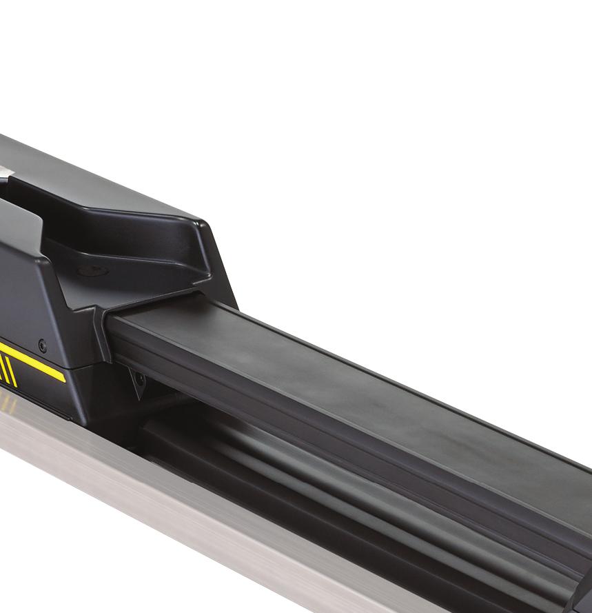
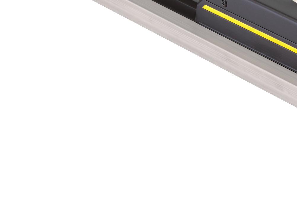
12 Introduction Product illustration F G H E B C D A A Foot end E Foot end interface B Floor plate F Cot fastener C Safety hook G Head end interface D Release button H Head end Important contact information For information about Federal Ambulance Specification KKK-A-1822F, contact: Chief, Automotive & Commodity Management Branch (QMDAA) Office of Motor Vehicle Management General Services Administration R2200 Crystal Drive, Suite 1006 Arlington, VA USA Telephone: For more information about AMD standards, contact: Ambulance Manufacturers Division (National Truck Equipment Association) Hills Tech Drive Farmington Hills, MI USA REV C
13 Introduction Contact information Contact Stryker Customer Service or Technical Support at: Stryker Medical 3800 E. Centre Avenue Portage, MI USA To view your operations or maintenance manual online, see Have the serial number (A) of your Stryker product available when calling Stryker Customer Service or Technical Support. Include the serial number in all written communication. Serial number location A Figure 1: Serial number location Date of manufacture The year of manufacture is the first four digits of the serial number REV C 9
14 Setup During setup, unpack the cartons and check all items for proper operation. Make sure that the product works properly before you place it in service. Remove all the shipping and packaging materials from the product before use. The condition of Performance-LOAD is the responsibility of the user. Have a qualified service person use the following list and the operation guide instructions to check Performance-LOAD functionality. 1. Confirm that the installation checklist is complete (Installation checklist on page 23). 2. If the installation checklist was completed by a third-party installer, the end user should repeat the installation checklist. Do not place Performance-LOAD into service if you cannot complete the installation checklist. Cot compatibility The Stryker Model 6392 Performance-LOAD system is compatible with cots with a Performance-LOAD compatible option. WARNING Performance-LOAD is designed to be compatible with the Performance-PRO XT, Power-PRO XT, and Power-PRO IT cots with a Performance-LOAD option. With the mass casualty option, you can use Performance-LOAD with a standard antler for most X-frame cots, but a rail clamp assembly and antler is required for all cots without a Performance-LOAD option. It is the responsibility of the cot operator to make sure that the cot being used in the Stryker Model 6392 Performance-LOAD system is a Performance-LOAD compatible cot. Injury may result if a non-compatible cot is used in the Stryker Model 6392 Performance-LOAD system. Cots that currently meet these specifications are: Model 6086 Performance-PRO XT with a Performance-LOAD option (factory installed) or compatibility kit ( ) Model 6506 Power-PRO XT with a Performance-LOAD option (factory installed) or compatibility kit ( or ) Model 6516 Power-PRO IT with a Performance-LOAD option (factory installed) or compatibility kit ( ) Model 6500 Power-PRO XT with a Performance-LOAD compatibility kit ( or ) REV C
15 Installation Quality system regulation The U.S. Food and Drug Administration (FDA) Code of Federal Regulations (CFR) Title 21 provides guidance regarding the installation of devices, such as the cot fastener system. To comply with these federal regulations, each device must be verified to have been properly installed by trained* individuals by following the inspection criteria in the installation checklist. This document must be maintained for a minimum of seven years for each serial number/installation. *The installation facility must maintain their own training records showing that the installer was qualified. CFR 21 SEC installation (a) Each manufacturer of a device requiring installation shall establish and maintain adequate installation and inspection instructions, and where appropriate test procedures. Instructions and procedures shall include directions for ensuring proper installation so that the device will perform as intended after installation. The manufacturer shall distribute the instructions and procedures with the device or otherwise make them available to the persons installing the device. (b) The person installing the device shall make sure that the installation, inspection, and any required testing are performed in accordance with the manufacturer s instructions and procedures and shall document the inspection and any test results to demonstrate proper installation. CFR 21 SEC general requirements WARNING Always install the cot fastener system as described in this manual. Improper installation can result in injury. Make sure that, at a minimum, your configuration is tested to meet the National Truck Equipment Association/Ambulance Manufacturer s Division Standard 004, Litter Retention System Static Test (AMD-004). Take special precautions regarding electromagnetic compatibility (EMC) when you use medical electrical equipment. Install and place the cot fastener system into service according to the EMC information in this manual. Portable and mobile RF communications equipment can affect the function of the cot fastener system. All records required by this part shall be maintained at the manufacturing establishment or other location that is reasonably accessible to responsible officials of the manufacturer and to employees of FDA designated to perform inspections. Such records, including those not stored at the inspected establishment, shall be made readily available for review and copying by FDA employee(s). Such records shall be legible and shall be stored to minimize deterioration and to prevent loss. Those records stored in automated data processing systems shall be backed up. (a) Confidentiality. Records deemed confidential by the manufacturer may be marked to aid FDA in determining whether information may be disclosed under the public information regulation in part 20 of this chapter. (b) Record retention period. All records required by this part shall be retained for a period of time equivalent to the design and expected life of the device, but in no case less than 2 years from the date of release for commercial distribution by the manufacturer REV C 11
16 Installation Installing the floor plate Install the Stryker universal floor plate in your vehicle patient compartment before you install your cot fastener system. See the Stryker Global Floor Plate Installation Manual ( ) for instructions. Performance-LOAD assembly kit checklist Make sure that you have all the required components to install the Performance-LOAD system. Performance-LOAD assembly kit components ( ) (2) Cleat ( ) (4) Cleat locator washer ( ) (4) Flat head cap screw ( ) (1) Center cover assembly ( ) (1) Hex wrench ( ) (1) Floor plate cover ( ) (1) Removal tool extension ( ) (1) (1) Figure 2: Performance-LOAD assembly kit components Note: Store the hex wrench and removal tool extension (Figure 3 on page 12) inside of the center cover assembly, so you can access these tools when you are Removing Performance-LOAD quickly on page (1) Figure 3: Hex wrench and removal tool extension REV C
17 Installation Selecting where to install Performance-LOAD Follow these steps to determine location and orientation of cleats and washer locations: 1. Select your sill to cot distance (A) (Figure 4 on page 13). Record your distance here: 2. Using the table below, select your Section based on your sill to cot distance (A). Record your section here: 3. Proceed to your section to install your cleats. A Figure 4: Sill to cot distance (A) Sill to cot distance (A) Section 5 in. (13 cm) Section A on page 14 6 in. (15 cm) Section B on page 14 7 in. (18 cm) Section C on page 14 8 in. (20 cm) Section D on page 15 9 in. (23 cm) Section E on page in. (25 cm) Section F on page in. (28 cm) Section G on page in. (30 cm) Section H on page in. (33 cm) Section I on page in. (36 cm) Section J on page in. (38 cm) Section K on page in. (41 cm) Section L on page in. (43 cm) Section M on page in. (46 cm) Section N on page in. (48 cm) Section O on page in. (51 cm) Section P on page in. (53 cm) Section Q on page REV C 13
18 Installation You can only insert cleats where indicated by. Use the necked area of the cleats to line up with the floor plate, so they drop in. Both cleats are identical and must be installed flat-side down. Both cleat dimensions are taken from the cap at the end of the floor plate. 1. Insert your first cleat (A) and slide toward the foot end. 2. Insert your second cleat (B). Foot end Head end 3. Determine your cleat ( ) and cleat locator washer ( ) locations per your Section below. 4. Using a 5/32 hex wrench, install four flat head cap screws ( ) and four cleat locator washers to secure the cleats. Make sure that you install two cleat locator washers per cleat. 5. Proceed to Installing Performance-LOAD on page 20. Section A: 5 in. (13 cm) sill to cot distance 8 (20.3 cm) 47 (119.4 cm) Section B: 6 in. (15 cm) sill to cot distance 9 (22.9 cm) 48 (121.9 cm) Section C: 7 in. (18 cm) sill to cot distance 10 (25.4 cm) 49 (124.5 cm) REV C
19 Installation You can only insert cleats where indicated by. Use the necked area of the cleats to line up with the floor plate, so they drop in. Both cleats are identical and must be installed flat-side down. Both cleat dimensions are taken from the cap at the end of the floor plate. 1. Insert your first cleat (A) and slide toward the foot end. 2. Insert your second cleat (B). Foot end Head end 3. Determine your cleat ( ) and cleat locator washer ( ) locations per your Section below. 4. Using a 5/32 hex wrench, install four flat head cap screws ( ) and four cleat locator washers to secure the cleats. Make sure that you install two cleat locator washers per cleat. 5. Proceed to Installing Performance-LOAD on page 20. Section D: 8 in. (20 cm) sill to cot distance 11 (27.9 cm) 50 (127.0 cm) Section E: 9 in. (23 cm) sill to cot distance 12 (30.5 cm) 51 (129.5 cm) REV C 15
20 Installation You can only insert cleats where indicated by. Use the necked area of the cleats to line up with the floor plate, so they drop in. Both cleats are identical and must be installed flat-side down. Both cleat dimensions are taken from the cap at the end of the floor plate. 1. Insert your first cleat (A) and slide toward the foot end. 2. Insert your second cleat (B). Foot end Head end 3. Determine your cleat ( ) and cleat locator washer ( ) locations per your Section below. 4. Using a 5/32 hex wrench, install four flat head cap screws ( ) and four cleat locator washers to secure the cleats. Make sure that you install two cleat locator washers per cleat. 5. Proceed to Installing Performance-LOAD on page 20. Section F: 10 in. (25 cm) sill to cot distance 6.5 (16.5 cm) 52 (132.1 cm) Section G: 11 in. (28 cm) sill to cot distance 7.5 (19.1 cm) 53 (134.6 cm) Section H: 12 in. (30 cm) sill to cot distance 8.5 (21.6 cm) 54 (137.2 cm) REV C
21 Installation You can only insert cleats where indicated by. Use the necked area of the cleats to line up with the floor plate, so they drop in. Both cleats are identical and must be installed flat-side down. Both cleat dimensions are taken from the cap at the end of the floor plate. 1. Insert your first cleat (A) and slide toward the foot end. 2. Insert your second cleat (B). Foot end Head end 3. Determine your cleat ( ) and cleat locator washer ( ) locations per your Section below. 4. Using a 5/32 hex wrench, install four flat head cap screws ( ) and four cleat locator washers to secure the cleats. Make sure that you install two cleat locator washers per cleat. 5. Proceed to Installing Performance-LOAD on page 20. Section I: 13 in. (33 cm) sill to cot distance 9.5 (24.1 cm) 55 (139.7 cm) Section J: 14 in. (36 cm) sill to cot distance 10.5 (26.7 cm) 56 (142.2 cm) Section K: 15 in. (38 cm) sill to cot distance 11.5 (29.2 cm) 57 (144.8 cm) REV C 17
22 Installation You can only insert cleats where indicated by. Use the necked area of the cleats to line up with the floor plate, so they drop in. Both cleats are identical and must be installed flat-side down. Both cleat dimensions are taken from the cap at the end of the floor plate. 1. Insert your first cleat (A) and slide toward the foot end. 2. Insert your second cleat (B). Foot end Head end 3. Determine your cleat ( ) and cleat locator washer ( ) locations per your Section below. 4. Using a 5/32 hex wrench, install four flat head cap screws ( ) and four cleat locator washers to secure the cleats. Make sure that you install two cleat locator washers per cleat. 5. Proceed to Installing Performance-LOAD on page 20. Section L: 16 in. (41 cm) sill to cot distance 12.5 (31.8 cm) 58 (147.3 cm) Section M: 17 in. (43 cm) sill to cot distance 13.5 (34.3 cm) 59 (149.9 cm) Section N: 18 in. (46 cm) sill to cot distance 14.5 (36.8 cm) 60 (152.4 cm) REV C
23 Installation You can only insert cleats where indicated by. Use the necked area of the cleats to line up with the floor plate, so they drop in. Both cleats are identical and must be installed flat-side down. Both cleat dimensions are taken from the cap at the end of the floor plate. 1. Insert your first cleat (A) and slide toward the foot end. 2. Insert your second cleat (B). Foot end Head end 3. Determine your cleat ( ) and cleat locator washer ( ) locations per your Section below. 4. Using a 5/32 hex wrench, install four flat head cap screws ( ) and four cleat locator washers to secure the cleats. Make sure that you install two cleat locator washers per cleat. 5. Proceed to Installing Performance-LOAD on page 20. Section O: 19 in. (48 cm) sill to cot distance 22 (55.9 cm) 61 (154.9 cm) Section P: 20 in. (51 cm) sill to cot distance 23 (58.4 cm) 62 (157.5 cm) Section Q: 21 in. (53 cm) sill to cot distance 24 (61.0 cm) 63 (160.0 cm) REV C 19
24 Installation Installing Performance-LOAD Tools required: Hack saw Slotted screwdriver Rubber hammer 3/8 Hex wrench (at least 5-3/8 in. (13.7 cm) length) 3/8 Drive torque wrench (ft-lb) > 60 ft-lb Silicone sealant Procedure: 1. Carefully place Performance-LOAD on top of the floor plate assembly. Align the two bolts at the head end with the two holes in the cleat as shown in Figure 5 on page 20. Figure 5: Performance-LOAD alignment 2. If you are not planning to install the floor plate caps, skip to step To install the floor plate caps, measure the exposed pocket at the head end and the foot end of the floor plate to customize the floor plate cap, which is included with the floor plate assembly kit ( ). See Installing the floor plate on page 12. Note: It is recommended that you add an additional 1 in. (2.5 cm) to the floor plate cap at the foot end to allow for overlap with Performance-LOAD. 4. Using a hack saw, cut two pieces of the floor plate cap to fit the measured length on both ends. The floor plate cap does not fit over the cleat. To cover a cleat, cut or remove the vertical tabs where they may interfere with the cleat (Figure 6 on page 20). Figure 6: Cut floor plate caps REV C
25 Installation Installing Performance-LOAD (Continued) 5. Using a rubber hammer, snap each floor plate cap into the floor plate (hook side first). Note: To unsnap the floor plate cap, use a slotted screwdriver on the side of the cover with a raised edge. 6. If your system is not equipped with inductive charging, skip to step If your system is equipped with inductive charging, follow steps Lay the excess wire into the floor plate pocket. Align the four holes with the mounting holes in the cleats. CAUTION Always place the wire inside the floor plate pocket, so the fastener assembly does not pinch the wire when you install the fastener assembly. 9. Connect the red and black wires from the fastener assembly to the anchor-to-vehicle cable ( ). Connect the red wire from the fastener assembly to the red wire on the anchor-to-vehicle cable. Connect the black wire from the fastener assembly to the black wire on the anchor-to-vehicle cable. Feed any excess wire through the electrical rubber grommet. Note: If you have a previously installed floor plate without the anchor-to-vehicle cable, measure either 3 in. or 7 in. toward the head end from the locator position A (Figure 7 on page 21). Mark the location in the middle of the channel. This will be your electrical inlet location. See Installing the floor plate ( ) for instructions about how to connect the electrical. Figure 7: Floor plate locator position - foot end Note: The safety hook (B) and extra mounting hole locations (C) are shown for reference only (Figure 7 on page 21). They are not used for Performance-LOAD installation. 10. Place the connectors into the floor plate pocket. 11. Apply silicone sealant to the electrical rubber grommet to completely seal the electrical pass through. WARNING Always seal all gaps to the exterior of the vehicle to prevent exhaust fumes from entering the vehicle patient compartment REV C 21
26 Installation Installing Performance-LOAD (Continued) 12. Rotate the spin caps (A) a half turn to access the attached floor plate bolts that are under the caps (Figure 8 on page 22). Note: Do not fully tighten the floor plate bolts until all four bolts are aligned and started. A B Figure 8: Attach the fastener 13. Using a 3/8 hex wrench, install the attached floor plate bolt that is closest to the head end. 14. Using a 3/8 hex wrench, install the other three attached floor plate bolts (A) into the two cleats (Figure 8 on page 22). 15. Using a torque wrench, tighten each floor plate bolt to 60±10 ft-lb. WARNING Always make sure that you tighten all four floor plate bolts to the recommended torque. 16. Close the spin caps. 17. Insert the un-notched side of the center cover assembly ( ) (B) into the opening in the head end housing (Figure 8 on page 22). 18. Drop the center cover assembly down to align with the floor plate. 19. Slide the center cover assembly into the opening in the foot end housing. 20. Continue to slide the center cover assembly toward the foot end until the post comes through the notch. 21. Complete the Installation checklist on page REV C
27 Installation checklist Follow this checklist with a Performance-LOAD compatible Power-PRO cot (model 6500, 6506, 6516) or Performance- PRO cot (Model 6086). Make sure that you do not have any unused components after installation. Your Performance-LOAD system does not ship with any extra components. If you have any unused components after installation, call Stryker service. Using a torque wrench, double check that all four attached floor plate bolts (A) are tightened 60+/-10 ft-lb. (Figure 8 on page 22). Visually check that all bolts and screws are properly tightened with no signs of protruding or missing fasteners. Lift the vehicle bumper to the raised position, if equipped. Load the Performance-LOAD compatible cot into Performance-LOAD. Check that the head end pin slides freely into the head end interface. If not, call Stryker service. Make sure that the cot is locked into Performance-LOAD by firmly pulling in and out and side to side on the foot end of the cot. Press the release button at the foot end of Performance-LOAD and push toward the head end to unlock the fastener. Pull to remove the cot from the vehicle patient compartment. Make sure that the cot is released. For Type II ambulances or if the cot center line is 17-1/2 in. or less from the vehicle wall, make sure that the optional wheel guide assembly ( ) is installed. Mark N/A if the wheel guide is not required. If equipped with inductive charging, install a depleted cot battery into a Performance-LOAD compatible Power- PRO cot, load the cot into Performance-LOAD. Make sure that the cot battery LED indicator is flashing green to indicate that it is charging. Product serial number: Installed by: Inspected by: Date: Date: Note: Maintain a copy of this record for at least seven years REV C 23
28 Operation Operating guidelines WARNING Always make sure of Performance-LOAD functionality before use. Failure may result in patient or operator injury. Always use caution when you move around in the vehicle patient compartment to avoid tripping on Performance- LOAD. Always use caution when you operate Performance-LOAD in adverse weather conditions (for example, rain, ice, snow). Always operate the cot or Performance-LOAD only when all persons are clear of the mechanisms. Entanglement in powered cot or Performance-LOAD mechanisms can cause serious injury. Always practice loading and unloading the cot with Performance-LOAD until operation of the product is fully understood. Improper use can cause injury. Do not allow untrained personnel to assist in the operation of Performance-LOAD. Untrained technicians/personnel can cause injury to the patient or themselves. Always use both hands when you handle the cot. Performance-LOAD is only an assisting device. Evaluate each situation to determine how to distribute and lift the weight that you are transporting. Always use enough operators to handle the forces that are required to load or unload when you handle weights over 400 lb (181 kg). To increase safety, operators should load or unload on flat surfaces. For 36 in. (91 cm) vehicle deck heights, you may need to manually unload. Always avoid extreme parking angles. Check Performance-LOAD for proper functionality before you start each shift. Operate Performance-LOAD with the vehicle on a flat surface, if possible. If you are unable to unload an occupied cot from the vehicle patient compartment, use a backboard to unload the patient. Removing Performance-LOAD quickly You can use the supplied tools to quickly remove Performance-LOAD from your vehicle patient compartment, if necessary. To quickly remove Performance-LOAD: 1. Remove the center cover assembly ( ) from the head end housing. 2. Remove the hex wrench and removal tool extension from the center cover assembly (Figure 9 on page 24). Figure 9: Hex wrench and removal tool extension REV C
29 Operation Removing Performance-LOAD quickly (Continued) 3. Rotate the spin caps a half turn to access the attached floor plate bolts that are under the caps 4. Insert the small end of the hex wrench ( ) into the removal tool extension ( ) to loosen the four bolts. Note: You cannot remove the four floor plate bolts as they are self contained within Performance-LOAD. 5. Carefully remove the fastener assembly from the floor plate assembly. 6. If equipped with inductive charging, disconnect the red wire from the red wire and the black wire from the black wire to disconnect the fastener assembly from the anchor-to-vehicle cable. To reinstall, see Installing Performance-LOAD on page 20. Checking the battery power level Use the cot battery LED indictor to check the SMRT Pak power level. A charged SMRT Pak, in working condition, provides up to 2 calls with a 250 pound patient (actual results may vary). The 24 VDC Power-PRO system and the SMRT Pak is rated for 2.4 amp-hours of electric energy. WARNING Do not remove the battery when the cot is active. CAUTION Always charge the cot battery before you place the product into service. An uncharged or depleted battery may cause poor product performance. To check the battery power level, press the retract (-) button on the cot control switch to activate the cot battery LED indicator. The cot battery LED indicator is located at the foot end control enclosure (shown as a battery symbol). The LED is solid green when the battery has a full charge or has an adequate battery power charge. Note: For best results, use the SMRT Pak until the cot battery LED indicator changes from solid green to flashing amber. The LED flashes amber when you need to charge or replace the battery Note: The cot battery LED indicator does not have to flash amber before you remove and replace the SMRT Pak, however, this is considered to be a best practice. You can remove and recharge the SMRT Pak at any time. The LED is a solid amber to indicate a battery error. Notes Only use Stryker approved batteries. If equipped with inductive charging, the powered cot fastener automatically charges the SMRT Pak battery. Automatic charging occurs when you lock the cot into the powered cot fastener (no cable or connectors required). The cot battery LED indicator flashes green for a moment to signify that it is charging. Automatic charging will only occur with SMRT Pak batteries. Using a non-upgraded X-frame cot for a mass casualty incident You can use some non-compatible cots, including most X-frame cots, in a a mass casualty incident when equipped with the mass casualty option for Performance-LOAD and a manual Stryker cot fastener. The loading and unloading operations are the same as the instructions for manual loading and unloading of a cot REV C 25
30 Operation Unloading a compatible cot from Performance-LOAD WARNING Always load or unload an occupied cot into a vehicle with a minimum of two trained operators. Always be ready to support the entire weight of the cot and patient when you unload a cot from the vehicle patient compartment. Always check for sheets, restraints, or debris that may catch in the cot transport wheels or load wheels. Do not extend the cot base while it is locked into Performance-LOAD. 1. Press and hold the release button at the foot end of the Performance-LOAD system and push the cot toward the head end of the vehicle patient compartment to relieve the load on the latch. 2. Grasp the cot frame at the foot end to pull the cot out of the vehicle patient compartment. For model 6500, model 6506 and model 6516 with Performance-LOAD: Operator 1: Grasp the cot frame at the foot end. While you support the weight of the cot, guide and pull the cot out of the vehicle patient compartment until the safety hook catches. Press and hold the extend (+) button on the cot control switch to extend the cot until the cot wheels rest on the ground. Operator 2: Grasp the outer rail to stabilize the cot. Unlatch the safety hook when the base is fully extended. For model 6086 with the Performance-LOAD: Operator 1: Grasp the cot frame. While you support the weight of the cot, guide and pull the cot out of the vehicle patient compartment until the safety hook catches. Operator 2: Grasp the base frame where indicated, lift slightly, and lower the base frame to its fully extended position while Operator 1 squeezes and holds the cot manual release. Make sure that the cot wheels are on the ground. Operator 1 (foot end): Release the cot manual release to lock the undercarriage into the extended position. Operator 2: Unlatch the safety hook when the base is fully extended. Loading a compatible cot into Performance-LOAD WARNING Always load or unload an occupied cot into a vehicle with a minimum of two trained operators. Always allow occupants to enter the vehicle patient compartment after the compatible cot has been loaded into the vehicle patient compartment. Always check for sheets, restraints, or debris that may catch in the cot transport or load wheels. CAUTION Do not push the cot into the vehicle patient compartment until you fully retract the cot base. 1. Lift the vehicle bumper to the raised position, if equipped. 2. Fully extend and lock the cot retractable head section before you load the cot into the powered cot fastener. 3. Place the cot in a loading position (any position where the loading wheels meet the vehicle patient compartment floor height) REV C
31 Operation Loading a compatible cot into Performance-LOAD (Continued) 4. Roll the cot to the open vehicle patient compartment. 5. Push the cot forward until the loading wheels are on the vehicle patient compartment floor and the safety bar passes the safety hook. Note: For maximum clearance to lift the base, pull the cot out until the safety bar is connected to the safety hook. For model 6500, model 6506, model 6516 with Performance-LOAD: Grasp the cot frame at the foot end. Lift the foot end of the cot and press and hold the retract (-) button on the cot control switch to fully retract the cot undercarriage. Note: The cot undercarriage will retract in less than three seconds. For model 6086 with Performance-LOAD: Operator 1 (foot end): Grasp the cot frame at the foot end. Squeeze and hold the cot manual release. Operator 2 (side): Grasp the outer rail to stabilize the cot. Then, grasp the base frame. After the foot end operator has lifted the cot and squeezed the cot manual release, retract the undercarriage with one hand and hold it in place. Operator 1 (foot end): Release the cot manual release to lock the undercarriage in the retracted position. 6. Push the cot into the vehicle patient compartment until the cot locks into the cot fastener. 7. Make sure that the cot is locked into the cot fastener by firmly pulling in and out and side to side on the foot end of the cot REV C 27
32 Cleaning CAUTION Do not clean, disinfect, service, or perform maintenance while the product is in use. Always use any appropriate personal protective equipment, such as goggles or respirator, to avoid the risk of inhaling contagion during cleaning. Use of power washing equipment can aerate contamination that collects during the use of the product. The product is power washable. The product may show some signs of oxidation or discoloration from continuous washing. No degradation of the product s performance will occur from power washing as long as you follow the proper procedures. Follow the cleaning solution manufacturer s dilution recommendations exactly. Power wash with recommended cleaners. Hose down the product and towel dry the guide. Power wash the rails and interface plates with a hand held wand unit or wipe the product with a clean cloth and recommended cleaners. Note: Water that gets into the Performance-LOAD system will drain through the drain tube to the underside of the vehicle REV C
33 Disinfecting CAUTION Do not clean, disinfect, service, or perform maintenance while the product is in use. Always wipe with clean water and dry each product after disinfecting. Some disinfectants are corrosive in nature and may cause damage to the product. If you do not rinse and dry the product, you may leave a corrosive residue on the surface of the product. This corrosive residue could cause premature degradation of critical components. Failure to follow these disinfecting instructions may void your warranty. In general, when used in concentrations recommended by the manufacturer, you can use either phenolic or quaternary (excluding Virex TB) type disinfectants. Iodophor type disinfectants are not recommended for use because staining may occur. The recommended disinfectants for this product s surfaces include the following: Quaternary (active ingredient - ammonium chloride) Phenolic (active ingredient - o-phenylphenol) Chlorinated bleach solution (use up to UK disinfecting 10,000 ppm available chlorine (941 ml of a 5.25% sodium hypochlorite solution per 4000 ml of water) Alcohol (active ingredient - 70% isopropyl alcohol) To wipe down the product with disinfectant between uses: 1. Follow the manufacturer s dilution recommendations exactly. 2. Apply the recommended disinfectant solution by spray or pre-soaked wipes. 3. Hand wash all surfaces of the product with the recommended disinfectant. 4. Disinfect all exposed surfaces. Pay attention to high contact areas. 5. Follow the disinfecting solution manufacturer s instructions for appropriate contact time and rinsing requirements. 6. Dry the product thoroughly before returning the product to service. Avoid over saturation. Do not allow the product to remain wet. Follow the manufacturer s dilution recommendations for appropriate contact time and rinsing requirements. Follow the chemical manufacturer s guidelines for proper disinfecting REV C 29
34 Preventive maintenance Establish and follow a maintenance schedule and keep records of the maintenance activity. Remove product from service before you perform the preventive maintenance inspection. You may need to perform preventive maintenance checks more often based on your level of product usage. Service only by qualified personnel. Every month Check Foot end interface and head end interface Routine Clean debris Every three months Check Loose fasteners Routine Replace if loose Every twelve months Check All parts Full functionality Routine Replace any worn parts, including covers, cot guides, and latch assembly, if necessary See the Installation checklist in the Operations Manual REV C
35 EMC information Guidance and manufacturer s declaration - electromagnetic emissions Performance-LOAD is intended for use in the electromagnetic environment specified below. The customer or the user of Performance-LOAD should assure that it is used in such an environment. Emissions test Compliance Electromagnetic environment RF Emissions CISPR 11 RF Emissions CISPR 11 Group 2 Class A The Performance-LOAD system must emit electromagnetic energy in order to perform its intended function. Nearby electronic equipment may be affected. The Performance-LOAD system is suitable for use in all establishments other than domestic and those directly connected to the public low-voltage power supply network that supplies buildings used for domestic purposes. Recommended separations distances between portable and mobile RF communications equipment and Performance-LOAD Performance-LOAD is intended for use in an electromagnetic environment in which radiated RF disturbances are controlled. The customer or the user of Performance-LOAD can help prevent electromagnetic interferences by maintaining a minimum distance between portable and mobile RF communications equipment (transmitters) and Performance-LOAD as recommended below, according to the maximum output power of the communications equipment. Rated maximum output power of transmitter W Separation distance according to frequency of transmitter m 150 khz to 80 MHz d=(1.2) ( P) 80 MHz to 800 MHz d=(.18) ( P) 800 MHz to 2.5 GHz d=(.35) ( P) For transmitters rated at a maximum output power not listed above, the recommended separation distance d in meters (m) can be estimated using the equation applicable to the frequency of the transmitter, where P is the maximum output power rating of the transmitter in watts (W) according to the transmitter manufacturer. Note 1: At 80 MHz and 800 MHz, the separation distance for the higher frequency range applies. Note 2: These guidelines may not apply in all situations. Electromagnetic propagation is affected by absorption and reflection from structures, objects, and people. Guidance and manufacturer s declaration - electromagnetic immunity Performance-LOAD is suitable for use in the electromagnetic environment specified below. The customer or the user of Performance-LOAD should assure that it is used in such an environment. Electromagnetic Immunity test EN/IEC test level Compliance level environment-guidance REV C 31
36 EMC information (Continued) Electrostatic discharge (ESD) IEC Power frequency (50/60 Hz) magnetic field IEC Guidance and manufacturer s declaration - electromagnetic immunity +8 kv contact +15 kv air +8 kv contact +15 kv air 30 A/m 30 A/m Note: U T is the a.c. mains voltage before applications of the test level. Floors should be wood, concrete, or ceramic tile. If floors are covered with synthetic material, the relative humidity should be at least 30%. Power frequency magnetic fields should be at levels characteristic of a typical location in a typical commercial or hospital environment REV C
37 EMC information (Continued) Guidance and manufacturer s declaration - electromagnetic immunity Conducted RF IEC Radiated RF IEC Vrms 150 khz to 80 MHz 10 V/m 80 MHz to 2.5 GHz 3 Vrms 10 V/m Portable and mobile RF communications equipment should be used no closer to any part of Performance- LOAD, including cables, than the recommended separation distance calculated from the equation appropriate for the frequency of the transmitter. Recommended separation distance D=(.35) ( P) 80 MHz to 800 MHz D=(0.70) ( P) 800 MHz to 2.5 GHz where P is the maximum output power rating of the transmitter in watts (W) according to the transmitter manufacturer and d is the recommended separation distance in meters (m). Field strengths from fixed RF transmitters, as determined by an electromagnetic site a should be less than the compliance level in each frequency range. b Interference may occur in the vicinity of equipment marked with the following symbol: Note 1: At 80 MHz and 800 MHz, the higher frequency range applies. Note 2: These guidelines may not apply in all situations. Electromagnetic propagation is affected by absorption and reflection from structures, objects, and people REV C 33
38 EMC information (Continued) Guidance and manufacturer s declaration - electromagnetic immunity a Field strengths from fixed transmitters, such as base stations for radio (cellular/cordless) telephones and land mobile radios, amateur radio, AM and FM radio broadcast, and TV broadcast cannot be predicted theoretically with accuracy. To assess the electromagnetic environment due to fixed RF transmitters, an electromagnetic site survey should be considered. If the measured field strength in the location in which Performance-LOAD is used exceeds the applicable RF compliance level above, the Performance-LOAD system should be observed to verify normal operation. If abnormal performance is observed, additional measures may be necessary, such as reorienting or relocating Performance-LOAD. b Over the frequency range 150 khz to 80 MHz, field strengths should be less than 3 V/m REV C
39 Warranty Stryker EMS, a division of the Stryker Corporation, offers one warranty option in the United States: Two (2) year parts and labor. Stryker EMS warrants to the original purchaser that its products should be free from manufacturing non-conformances that affect product performance and customer satisfaction for a period of two (2) years after date of delivery. Stryker s obligation under this warranty is expressly limited to supplying replacement parts and labor for, or replacing, at its option, any product that is, in the sole discretion of Stryker, found to be defective. Expendable components, i.e. mattresses, restraints, IV poles, storage nets, storage pouches, oxygen straps, and other soft goods, have a one (1) year limited warranty. The Stryker Performance-LOAD is designed for a 7 year expected service life under normal use conditions, and with appropriate periodic maintenance as described in the maintenance manual. Stryker warrants to the original purchaser that the welds on the Performance-LOAD will be free from structural defects for the expected 7 year life of the product as long as the original purchaser owns the product. Upon Stryker s request, purchaser shall return to Stryker s factory any product or part (freight prepaid by Stryker) for which an original purchaser makes a warranty claim. Warranty exclusions and other conditions: Any improper use or alteration or repair by unauthorized service providers in such a manner as in Stryker s judgment affects the product materially and adversely, shall void this warranty. Any repair of Stryker products using parts not provided or authorized by Stryker shall void this warranty. There are extenuating circumstances and events that may alter the performance of the products such as an ambulance accident. In Stryker s discretion, certain circumstances may allow for evaluation of the product post ambulance accident which could allow for continued use of the product. If products recommended to be removed from service are put back into service, Stryker will consider the product as being subject to unusual stress and improperly maintained. Products which are subject to unusual stress and improper maintenance are not subject to Stryker s warranty as noted above. In addition, Stryker will not indemnify any customer for any third-party claims related to injuries caused by products that have been involved in accidents. This warranty is void if the label bearing the serial number of the product has been removed of defaced. This warranty is void if the product is not purchased from an authorized Stryker dealer. This statement constitutes Stryker EMS s entire warranty with respect to the aforesaid equipment. Stryker makes no other warranty or representation either expressed or implied, except as set forth herein. There is no warranty on merchantability and there are no warranties of fitness for any particular purpose. In no event shall Stryker be liable hereunder for incidental or consequential damages arising from or in any matter related to sales or use of such equipment. No employee or representative of Stryker is authorized to change this warranty in any way. Warranty exclusion and damage limitations The express warranty set forth herein is the only warranty applicable to the product. Any and all other warranties, whether express or implied, including any implied warranty of merchantability or fitness for a particular purpose are expressly excluded by Stryker. In no event shall Stryker be liable for incidental or consequential damages. To obtain parts and service Stryker products are supported by a nationwide network of dedicated Stryker Field Service Representatives. These representatives are factory trained, available locally, and carry a substantial spare parts inventory to minimize repair time. Simply call your local representative or call Stryker Customer Service at REV C 35
40 Warranty Return authorization Product cannot be returned without prior approval from the Stryker Customer Service Department. An authorization number will be provided which must be printed on the returned product. Stryker reserves the right to charge shipping and restocking fees on returned product. Special, modified, or discontinued products are not subject to return. Damaged product ICC Regulations require that claims for damaged product must be made within fifteen (15) days of receipt of the product. Do not accept damaged shipments unless such damage is noted on the delivery receipt at the time of receipt. Upon prompt notification, Stryker will file a freight claim with the appropriate carrier for damages incurred. Claims will be limited in amount to the actual replacement cost. In the event that this information is not received by Stryker within the fifteen (15) day period following the delivery of the product, or the damage was not noted on the delivery receipt at the time of receipt, the customer will be responsible for payment of the original invoice in full within thirty (30) days of receipt. Claims for any incomplete shipments must be made within thirty (30) days of invoice. International warranty clause This warranty reflects U.S. domestic policy. Warranty outside the U.S. may vary by country. Contact your local Stryker Medical representative for additional information REV C

41 Stryker Medical 3800 E. Centre Avenue Portage, MI USA 2016/ REV C
2018/ Rev E.4
 Performance-LOAD Cot Fastener System Maintenance Manual 6392 EN 6392-009-002 Rev E.4 2018/06 Symbols Refer to instruction manual/booklet Operating instructions/consult instructions for use General warning
Rev C /08
 M-1 Cot Fastener Maintenance Manual 6373 6376 6381 EN 6373-009-002 Rev C.0 2018/08 Symbols Operating instructions/consult instructions for use General warning Caution Catalogue number Lot (batch) code
EMS Equipment. Power-LOAD power-loading cot fastener system
 EMS Equipment Power-LOAD power-loading cot fastener system Power-LOAD power-loading cot fastener system Shown with optional accessories. Reduce the risk of injuries when loading and unloading cots Power
Prime TC Transport Chair Operations Manual. 2016/09 A REV A
 Prime TC Transport Chair 1460 Operations Manual 2016/09 A.2 1460-109 -001 REV A www.stryker.com sample text Symbols Operating instructions General warning Caution Warning; crushing of hands No pushing
CUB Pediatric Crib FL19H (190) Operations Manual
 Operations Manual") CUB Pediatric Crib FL19H (190) Operations Manual 2017/06 A.3 1900-109-001 REV A www.stryker.com sample text Symbols General Warning Caution Operating instructions/consult instructions for use CE mark Safe
CUB Pediatric Crib FL19H (190) Operations Manual 2017/06 A.3 1900-109-001 REV A www.stryker.com sample text Symbols General Warning Caution Operating instructions/consult instructions for use CE mark Safe
Charging Station - Instructions For Use
 Charging Station - Instructions For Use READ THE HYBRESIS CONTROLLER AND PATCH INSTRUCTIONS FOR USE FOR ADDITIONAL IMPORTANT INFORMATION. REF: 199586 GLOSSARY OF SYMBOLS This device may contain one or
HEINE NT4 MED V
 HEINE NT4 MED 113594 2018-01-23 V-200.00.601 HEINE NT4 Please read and follow these instructions for use and keep them for future reference. Intended Use The HEINE charger NT4 is to be used exclusively
INSTALLATION AND OPERATING INSTRUCTIONS OF THE INTERNATIONAL ISOBOX SERIES ISOLATION TRANSFORMERS.
 INSTALLATION AND OPERATING INSTRUCTIONS OF THE INTERNATIONAL ISOBOX SERIES ISOLATION TRANSFORMERS. Before installing and/or using this product, please check for any visual damage of the enclosure, power
UNIVERSAL BATTERY CHARGER II
 UNIVERSAL BATTERY CHARGER II USER S MANUAL TABLE OF CONTENTS INTRODUCTION General Information 2 Intended use 2 Compatibility 2 Abbreviations 2 Safety precautions 3 Scope of delivery 3 Storage and transport
Blades with the MatrixPRO Driver may result in damage to the MatrixPRO Driver and/or screwdriver blades, and should
 Description: The MatrixPRO Driver (05.000.020) is designed to insert DePuy Synthes MatrixNEURO TM Self Drilling Screws (3 4mm lengths) and Low Profile Neuro Self Drilling Screws (3 4mm lengths) and features
Operator's Manual. Storage System. Ultrasound Probe Cabinet. Manufactured by:
 Storage System Ultrasound Probe Cabinet Operator's Manual Manufactured by: CIVCO Medical Solutions 102 First Street South Kalona, IA 52247 USA 319.248.6757 / 800.445.6741 WWW.CIVCO.COM Copyright 2018 All
Power Blade Charger Users Guide
 Power Blade Charger Users Guide Desktop Configuration Wall Mount Configuration Desktop Configuration (Displayed with Jaco Power Blade Batteries and 300 Series Laptop and LCD carts. Sold separately) 25-0180
INSTALLATION AND OPERATING INSTRUCTIONS OF THE INTERNATIONAL ISOBOX SERIES ISOLATION TRANSFORMERS.
 INSTALLATION AND OPERATING INSTRUCTIONS OF THE INTERNATIONAL ISOBOX SERIES ISOLATION TRANSFORMERS. Before installing and/or using this product, please check for any visual damage of the enclosure, power
Model 521 Universal Oxygen Cylinder Bracket
 Model 521 Universal Oxygen Cylinder Bracket and Users' Manual Notice to Installer This manual contains instructions for installing, using, and maintaining the Model 521 Universal Oxygen Cylinder Bracket.
BRAKE RETROFIT INSTRUCTION MANUAL
 IMPORTANT Keep manual on file at all times. Model 6080 202 Ambulance Cot WHEEL BRAKE RETROFIT INSTRUCTION MANUAL For Parts or Technical Assistance 1 800 327 0770 Table of Contents Introduction................................................................................
VHM-P (Non-Locking) and VHM-PL (Locking) Variable Height Arm with Slide-In Mounting Plate
 and VHM-PL (Locking) Variable Height Arm with Slide-In Mounting Plate") 3875 Cypress Drive Petaluma, CA 94954 800.228.2555 +1.707.773.1100 Fax 707.773.1180 www.gcx.com VHM-P (Non-Locking) and VHM-PL (Locking) Variable Height Arm with Slide-In Mounting Plate (Refer to qualified
3875 Cypress Drive Petaluma, CA 94954 800.228.2555 +1.707.773.1100 Fax 707.773.1180 www.gcx.com VHM-P (Non-Locking) and VHM-PL (Locking) Variable Height Arm with Slide-In Mounting Plate (Refer to qualified
Table of Contents. Adjusting the Wheel Locking Force Wheel Lock Assembly and Parts List Preventive Maintenance Checklist...
 WHEEL LOCK RETROFIT INSTRUCTION MANUAL Medical Model 6080-201 Rugged Ambulance Cot Important Information File in your maintenance records For parts or technical assistance call 800 327 0770 (option 2)
SeekTech Inductive Clamp
 Inductive Clamp Manual SeekTech Inductive Clamp! Read this Operator s Manual carefully before using this tool. Failure to understand and follow the contents of this manual may result in electrical shock,
Universal Battery Charger II.
 Universal Battery Charger II. Instructions for Use This publication is not intended for distribution in the USA. Instruments and implants approved by the AO Foundation Table of Contents Introduction General
(Refer to qualified personnel)
") 3875 Cypress Drive Petaluma, CA 94954 800.228.2555 +1.707.773.1100 Fax 707.773.1180 www.gcx.com Installation Guide VHM-P (Non-Locking) and VHM-PL (Locking) Variable Height Arm (Slide-Above-Arm Configuration)
3875 Cypress Drive Petaluma, CA 94954 800.228.2555 +1.707.773.1100 Fax 707.773.1180 www.gcx.com Installation Guide VHM-P (Non-Locking) and VHM-PL (Locking) Variable Height Arm (Slide-Above-Arm Configuration)
OAKWORKS 300 Series Procedure Chair
 User MANUAL OAKWORKS 300 Series Procedure Chair www.oakworksmed.com 717.235.6807 made in the USA with US & imported parts Copyright 2013 OAKWORKS, Inc. Notice This manual was originally drafted and approved
3875 Cypress Drive Petaluma, CA Fax
 3875 Cypress Drive Petaluma, CA 94954 800.228.2555 +1.707.773.1100 Fax 707.773.1180 www.gcx.com VHM-P (Non-Locking) Variable Height Arm with Fixed Angle Front End for Flat Panel / Keyboard Bracket (L Brackets
EMS equipment catalog
 This document is intended solely for the use of healthcare professionals. A healthcare professional must always rely on his or her own professional clinical judgment when deciding whether to use a particular
SRK12KX Battery-powered Crimping Tool
 OPERATION MANUAL Serial Number SRK12KX Battery-powered Crimping Tool Read and understand all of the instructions and safety information in this manual before operating or servicing this tool. 52080066
Eaton Battery Charger Module Models ASY-0652 and ASY-0675 User s Guide
 Eaton 9170 + Battery Charger Module Models ASY-0652 and ASY-0675 User s Guide Class A EMC Statements FCC Part 15 NOTE This equipment has been tested and found to comply with the limits for a Class A digital
Fixed Ceiling Lift FL
 Savaria Fixed Ceiling Lift FL OWNER S MANUAL To Be Retained by Owner After Installation by Authorized Savaria Dealer Part No. 001108-EN Rev. 00 -m -201 2 IMPORTANT Be sure to read this entire manual before
PAD-MOUNTED SWITCHGEAR INSPECTION & MAINTENANCE RECOMMENDATIONS TYPE PSI/II. 15kV 25kV. Qualified Persons
 Page 1 Qualified Persons... 1 Safety Information... 2 Procedures... 3 Maintenance... 3 Security Inspection (Exterior)... 3 Verify Securing Devices... 3 Maintaining the Exterior... 3 Replacing Labels...
OAKWORKS 300 Series Procedure Chair
 USER MANUAL OAKWORKS 300 Series Procedure Chair www.oakworksmed.com 717.235.6807 made in the USA with US & imported parts Copyright 2013 OAKWORKS, Inc. Notice This manual was originally drafted and approved
MatrixPRO Driver Instructions for Use
 DESCRIPTION: The MatrixPRO Driver (05.000.020) is designed to insert DePuy Synthes MatrixNEURO TM Self-Drilling Screws (3-4mm lengths) and Low Profile Neuro Self-Drilling Screws (3-4mm lengths) and features
VHM-P (Non-Locking) Variable Height Arm with VESA Mounting Plate for 75 x 75mm or 100 x 100mm applications
 Variable Height Arm with VESA Mounting Plate for 75 x 75mm or 100 x 100mm applications") 3875 Cypress Drive Petaluma, CA 94954 800.228.2555 +1.707.773.1100 Fax 707.773.1180 www.gcx.com VHM-P (Non-Locking) Variable Height Arm with VESA Mounting Plate for 75 x 75mm or 100 x 100mm applications
3875 Cypress Drive Petaluma, CA 94954 800.228.2555 +1.707.773.1100 Fax 707.773.1180 www.gcx.com VHM-P (Non-Locking) Variable Height Arm with VESA Mounting Plate for 75 x 75mm or 100 x 100mm applications
Installer Guide smart connect
 Installer Guide smart connect TM 7490 Wireless Remote Outdoor Sensor Please read all instructions before proceeding. The wireless remote outdoor sensor monitors temperature at a remote outdoor location
Owner s Manual Ultra DBI TM Model: 9400
 Owner s Manual Ultra DBI TM Model: 9400 Owner Model Serial # Date Medical Positioning, Inc. 1146 Booth Street, Kansas City, Kansas 66103 T: 816-474-1555 1-800-593-3246 www.medicalpositioning.com Table
1250 LB. CAPACITY MECHANICAL WHEEL DOLLY
 1250 LB. CAPACITY MECHANICAL WHEEL DOLLY 67287 SET-UP AND OPERATING INSTRUCTIONS Visit our website at: http://www.harborfreight.com Read this material before using this product. Failure to do so can result
INSTALLATION INSTRUCTIONS WINCH MOUNTING KIT Part Number: Application: Honda Rancher TRX420
 INSTALLATION INSTRUCTIONS WINCH MOUNTING KIT Part Number: 75660 Application: Honda Rancher TRX420 Your safety, and the safety of others, is very important. To help you make informed decisions about safety,
LED OPERATORY LIGHT Instructions For Use
 OVERVIEW Post Mount Light LP4000 / LP4050 LP5000 / LP5050 Ceiling Mount Light LC4000 / LC4050 LC5000 / LC5050 System Mount Light LS4000 / LS4050 LS5000 / LS5050 Track Mount Light LT4000 / LT4050 LT5000
Table of Contents. I.V. Pole Mounting Assembly, Left Stage I.V. Assembly, Left Stage I.V. Pole Assembly... 67
 Operations/ Maintenance Manual Important Information File in your maintenance records Medical Model 6081 Rugged MX-PRO R3 Incubator Transport For parts or technical assistance call 800 327 0770 (option
Auto-Lift Operating System
 Installation Instructions Parasol Cellular Shades Auto-Lift Operating System CONTENTS Getting Started: Product View... 1 Tools and Fasteners Needed... 2 Installation: Installation Overview... 3 STEP 1
k EDR /11. S cape OWNERS MANUAL. S cape Platform. Silhouette. Pro-motion. Bronze. [ power foundations ]
![k EDR /11. S cape OWNERS MANUAL. S cape Platform. Silhouette. Pro-motion. Bronze. [ power foundations ]](/thumbs/87/96491583.jpg "k EDR /11. S cape OWNERS MANUAL. S cape Platform. Silhouette. Pro-motion. Bronze. [ power foundations ]") 99300787-k EDR11739 4/11 OWNERS MANUAL S cape S cape Platform Silhouette Pro-motion Bronze [ power foundations ] contents Advisory... 3 Acoustics... 5 Installation... 6 Turnbuckle Adjustment... 18 Troubleshooting...
99300787-k EDR11739 4/11 OWNERS MANUAL S cape S cape Platform Silhouette Pro-motion Bronze [ power foundations ] contents Advisory... 3 Acoustics... 5 Installation... 6 Turnbuckle Adjustment... 18 Troubleshooting...
Owner's/Installation Manual
 Owner's/Installation Manual Power Management Module (PMM) and Starter Kit NOTE: The starter kit must be purchased and installed prior to individual PMM usage. Model Numbers: 00686-0 PMM 00699-0 PMM WITH
OAKWORKS 100 Series Procedure Chair
 USER MANUAL OAKWORKS 100 Series Procedure Chair Model 121A Model 100 www.oakworks.com 717.235.6807 Copyright 2018 OAKWORKS, Inc. Notice Printed in U.S.A. All rights are reserved. No part of this document
ELORA BATTERY INTERFACE. Owner s Manual
 ELORA BATTERY INTERFACE Owner s Manual CONTENTS 3 4 7 8 12 19 IMPORTANT READ AND UNDERSTAND THIS MANUAL BEFORE OPERATION INTRODUCTION KEY FEATURES AND BENEFITS ORDERING INFORMATION MOUNTING FUEL GAUGE
Installation Manual for Philips Intellivue MP5/20/30 VHM-25 Channel Mount Kit
 3875 Cypress Drive Petaluma, CA 94954 800.228.2555 707.773.1100 Fax 707.773.1180 www.gcx.com Installation Manual for Philips Intellivue MP5/20/30 VHM-25 Channel Mount Kit Install Time: 10-15 minutes The
Invacare. Battery Charger User Manual. Model: POC1 115, POC1 115 AZ, POC1 115 C, POC1 115 EU
 Invacare Model: POC1 115, POC1 115 AZ, POC1 115 C, POC1 115 EU en Battery Charger User Manual This manual MUST be given to the user of the product. BEFORE using this product, read this manual and save
Shielded Connector Block for the NI PXI/PXIe-2532/2532B
 INSTALLATION INSTRUCTIONS NI Shielded Connector Block for the NI PXI/PXIe-53/53B This document describes how to install and connect signals to the National Instruments shielded connector block. Use the
Owner s Manual EchoBed X VasScan Table X
 Owner s Manual EchoBed X VasScan Table X Owner Model Serial # Date Echo/Vascular User Manual (15381-C) Page 1 of 46 DCR-00172 Table of Contents Symbols and Definitions... 3 Safety Warnings & Cautions...
PM-X IR SURGICAL POWER & ACCESSORIES
 PM-X12-700-IR-12.13 SURGICAL POWER & ACCESSORIES Table of Contents Introduction Page 4 Intended Use Page 4 Warnings Page 4 Cautions Page 6 Explanation of Symbols Page 7 Features Page 8 Battery Pack - Installation
(SDU 50, SDU 90, and BKSDU) Shortening Disposal Unit * * Installation, Operation, Service, and Parts Manual
 Shortening Disposal Unit * * Installation, Operation, Service, and Parts Manual") Shortening Disposal Unit (SDU 50, SDU 90, and BKSDU) Installation, Operation, Service, and Parts Manual Frymaster, a member of the Commercial Food Equipment Service Association, recommends using CFESA
Shortening Disposal Unit (SDU 50, SDU 90, and BKSDU) Installation, Operation, Service, and Parts Manual Frymaster, a member of the Commercial Food Equipment Service Association, recommends using CFESA
DIGITAL BATTERY TORQUE WRENCH (BC-RAD SELECT) USER GUIDE
 USER GUIDE") DIGITAL BATTERY TORQUE WRENCH (BC-RAD SELECT) USER GUIDE W.CHRISTIE (INDUSTRIAL) LTD CHRISTIE HOUSE, MEADOWBANK ROAD, ROTHERHAM, SOUTH YORKSHIRE, S61 2NF, UK T: +44(0)1709 550088 F: +44(0)1709 550030 E:
DIGITAL BATTERY TORQUE WRENCH (BC-RAD SELECT) USER GUIDE W.CHRISTIE (INDUSTRIAL) LTD CHRISTIE HOUSE, MEADOWBANK ROAD, ROTHERHAM, SOUTH YORKSHIRE, S61 2NF, UK T: +44(0)1709 550088 F: +44(0)1709 550030 E:
Renaissance Series Full Length X Ray Stretcher OPERATIONS MANUAL. For Parts or Technical Assistance
 Renaissance Series 1026 Full Length X Ray Stretcher OPERATIONS MANUAL For Parts or Technical Assistance 1 800 327 0770 Table of Contents INTRODUCTION.......................................................................
Technical Manual. DLM Module. This manual should remain with the unit.
 Technical Manual DLM Module This manual should remain with the unit. Safety Rules SAVE THESE INSTRUCTIONS! Read the following information carefully before attempting to install, operate or service this
User MANUAL. PG Series. Ultrasound Series. Ultrasound series. made in the USA with US & imported parts
 User MANUAL PG Series & Ultrasound Series PG Series Ultrasound series made in the USA with US & imported parts www.oakworksmed.com 717.235.6807 Copyright 2010 OAKWORKS, Inc. Notice This manual was originally
1000 Emergency Care Stretcher 1500 PACU Stretcher OPERATIONS MANUAL. For Parts or Technical Assistance
 1000 Emergency Care Stretcher 1500 PACU Stretcher OPERATIONS MANUAL For Parts or Technical Assistance 1 800 327 0770 Table of Contents INTRODUCTION........................................................................
SV1 Electric Hospital Bed Maintenance Manual
 SV Electric Hospital Bed 700 Maintenance Manual 07/0 SM-700 REV 0 www.stryker.com sample text Symbols Refer to instruction manual/booklet Operating instructions / Consult instructions for use General warning
DISPLACEMENT PUMP INSTRUCTIONS-PARTS LIST Rev. K. Model , Series A Model , Series B Model , Series A
 INSTRUCTIONS-PARTS LIST INSTRUCTIONS This manual contains important warnings and information. READ AND KEEP FOR REFERENCE. DISPLACEMENT PUMP 308190 Rev. K 3000 psi (210 bar) MAXIMUM WORKING PRESSURE Model
Powerware Vdc Extended Battery Cabinet User s Guide.
 Powerware 9125 48 Vdc Extended Battery Cabinet User s Guide www.powerware.com FCC Part 15 Class A EMC Statements NOTE This equipment has been tested and found to comply with the limits for a Class A digital
Extended Battery Cabinet for Nfinity
 POWER PROTECTION Extended Battery Cabinet for Nfinity USER MANUAL TABLE OF CONTENTS IMPORTANT SAFETY INSTRUCTIONS................................... 1 ELECTROMAGNETIC COMPATIBILITY.......................................
Fabric Replacement Top and Doors with Tinted Side and Rear Curtains Installation Instructions
 Fabric Replacement Top and Doors with Tinted Side and Rear Curtains Installation Instructions For: Wrangler/TJ 1997-2002 Part Number: 51124 www.bestop.com DO NOT INSTALL THIS PRODUCT ON ANY VEHICLE OTHER
Shortening Disposal Unit
 Shortening Disposal Unit (SDU 50, 90, 100 and BKSDU) Installation, Operation, Service and Parts Manual Frymaster, a member of the Commercial Food Equipment Service Association, recommends using CFESA Certified
OAKWORKS PF Series Tables
 User MANUAL OAKWORKS PF Series Tables PF400 Shown with optional Adjustable Side Arm Rests and Universal Table Extender PF250 PF200 Shown with optional QuickLock Face rest platform and Boiance crescent
will result in death or serious injury. could result in death or serious injury. Indicates a hazardous situation which, if not avoided,
 SAFETY SETUP OPERATION MAINTENANCE WARNING SYMBOLS AND DEFINITIONS This is the safety alert symbol. It is used to alert you to potential personal injury hazards. Obey all safety messages that follow this
SAFETY INFORMATION & INSTALLATION GUIDE RMX Programmable Power Supplies. About the RMX Safety Information & Installation Guide
 SAFETY INFORMATION & INSTALLATION GUIDE RMX Programmable Power Supplies RMX-4120/4121/4122/4123/4124/4125/4126/4127 About the RMX Safety Information & Installation Guide This guide is intended for users
Operations Manual. Birthing Bed. Model LD304. For Parts or Technical Assistance: USA: (option 2) Canada:
 Canada:") Birthing Bed Model LD304 Operations Manual For Parts or Technical Assistance: USA: 1-800-327-0770 (option 2) Canada: 1-888-233-6888 2007/01 4701-109-001 REV C www.stryker.com Table of Contents Introduction..............................................................................
Birthing Bed Model LD304 Operations Manual For Parts or Technical Assistance: USA: 1-800-327-0770 (option 2) Canada: 1-888-233-6888 2007/01 4701-109-001 REV C www.stryker.com Table of Contents Introduction..............................................................................
Visum XBlade LED Exam Light. Operations Manual
 Visum XBlade LED Exam Light Operations Manual Contents S 1. Indications for Use...5 1.1 Device Description...5 1.2 Intended User Profile...5 2. Warnings and Cautions...6 2.1 Warnings...6 2.2 Cautions...7
EMS Equipment. powered ambulance cot. Because lives depend on it.
 EMS Equipment Power-pro powered ambulance cot Because lives depend on it. Power-PRO powered ambulance cot power to reduce the risk of injury Field studies show that the Stryker Power-PRO could save your
Simplicity Light Post Mount
 Simplicity Light Post Mount Table of Contents Section I Introduction Specifications... 2 Classifications...2-3 Packaging... 3 Section II Installation Post Mount with Service Console...4-5 Section III Operation
Quickdraw. Model 2400 Series. Operating Instructions & Maintenance Manual. Clearing The Airway Is Our #1 Priority
 Quickdraw Model 2400 Series Clearing The Airway Is Our #1 Priority Operating Instructions & Maintenance Manual, INC. 11064 Randall Street Sun Valley, CA 91352 USA www.sscor.com Email: marketing@sscor.com
INSTALLATION & OWNER S MANUAL
 Rev. L p. 1 of 16 INSTALLATION & OWNER S MANUAL V4262 CAMO (SOFT SIDED) CAB KIT INSTALLATION & OWNER S MANUAL The contents of this envelope are the property of the owner. Be sure to leave with the owner
Shortening Disposal Unit
 Shortening Disposal Unit Installation, Operation, Service and Parts Frymaster, a member of the Commercial Food Equipment Service Association, recommends using CFESA Certified Technicians. 24-Hour Service
VEGETABLE OIL DISPOSAL UNIT (MSDU) OPERATOR & SERVICE MANUAL
 OPERATOR & SERVICE MANUAL") VEGETABLE OIL DISPOSAL UNIT (MSDU) OPERATOR & SERVICE MANUAL MANUFACTURED BY P.O. BOX 51000 SHREVEPORT, LOUISIANA 71135-1000 PHONE 1-318-865-1711 1-800-24 FRYER This equipment chapter is to be inserted
VEGETABLE OIL DISPOSAL UNIT (MSDU) OPERATOR & SERVICE MANUAL MANUFACTURED BY P.O. BOX 51000 SHREVEPORT, LOUISIANA 71135-1000 PHONE 1-318-865-1711 1-800-24 FRYER This equipment chapter is to be inserted
i3000s/i2000 Flex AC Current Probe
 i3000s/ AC Current Probe Instruction Sheet Introduction The i3000s 24 Flex, i3000s 36 Flex, and AC Current Probes (the Probe) are used with oscilloscopes, digital multimeters, recorders or data loggers.
Condor Manual. Corporation
 Condor Manual Corporation PREFACE IMPORTANT, PLEASE READ CAREFULLY Thank you for your purchase with Amico Accessories Inc. This unit is designed for long lasting performance, providing the end user complies
Resuscitation System Model 100
 Resuscitation System Model 100 AutoPulse Power System User Guide P/N. 12457-001 Rev. 4 Notice About this Guide The information in this User Guide applies to the ZOLL AutoPulse Power System designed for
100 Watt Power Amp 50 Watts x 50 Watts Single Rack Space
 User's Manual 100 Watt Power Amp 50 Watts x 50 Watts Single Rack Space 1 Introduction Congratulations on your purchase of the Rocktron Velocity 100LTD power amplifier! The Velocity 100LTD was designed
US Water ORP Booster Injection System
 US Water ORP Booster Injection System US Water Systems, Inc. 1209 Country Club Road Indianapolis, IN 46234 1-800-608-8792 info@uswatersystems.com www.uswatersystems.com REVISION 1.1, 9-14-15 Table of Contents
Owner s Manual & Safety Instructions
 Owner s Manual & Safety Instructions Save This Manual Keep this manual for the safety warnings and precautions, assembly, operating, inspection, maintenance and cleaning procedures. Write the product s
The RICON Eclipse F8000 (A) Series Export Use Wheelchair and Standee Lift is installed in a
 Series Export Use Wheelchair and Standee Lift is installed in a") II. INSTALLATION TABLE OF CONTENTS The RICON Eclipse F8000 (A) Series Export Use Wheelchair and Standee Lift is installed in a cassette mounted to the underside of the vehicle and behind the bottom step
II. INSTALLATION TABLE OF CONTENTS The RICON Eclipse F8000 (A) Series Export Use Wheelchair and Standee Lift is installed in a cassette mounted to the underside of the vehicle and behind the bottom step
Western Products, PO Box , Milwaukee, WI MOUNT KIT
 Western Products, PO Box 245038, Milwaukee, WI 53224-9538 www.westernplows.com January 1, 2009 Lit. No. 67941, Rev. 02 67865 MOUNT KIT Chevy/GMC 1500/2500/3500 4X4 1988-98 Chevy/GMC 2500 & 3500 Classic
INSTRUCTION MANUAL. CAT Place Table Top Centrifuge
 1 INSTRUCTION MANUAL CAT. 72359-06 6-Place Table Top Centrifuge 2 CONTENTS IMPORTANT SAFETY GUIDELINES PLEASE READ BEFORE USE.. 3 SUPPLIED EQUIPMENT... 5 OPTIONAL ACCESSORIES... 5 SETUP... 5 UNPACKING...
IMPORTANT SAFETY INSTRUCTIONS
 Table of Contents Safety... 2 Specifications... 3 Functions... 4 Operation... 5 Maintenance... 7 Warranty... 7 SAFETY SPECIFICATIONS OPERATION MAINTENANCE WARNING SYMBOLS AND DEFINITIONS This is the safety
Installation Manual for VHM-25 Series Arms Channel Mount
 3875 Cypress Drive Petaluma, CA 94954 800.228.2555 707.773.1100 Fax 707.773.1180 www.gcx.com Installation Manual for VHM25 Series Arms Channel Mount Install Time: 1015 minutes The purpose of this manual
CONTENTS DESCRIPTION UNPACKING DIMENSIONS
 INSTALLATION INSTRUCTIONS Recessed Luminaire ModelNo.FV-NLF6RES CONTENTS GENERAL SAFETY INFORMATION DESCRIPTION UNPACKING SUPPLIED ACCESSORIES DIMENSIONS WIRING DIAGRAM INSTALLATION (BETWEEN JOISTS MOUNTING)
Gavita HortiStar 1000 DE EU/US
 Pro line Gavita HortiStar 1000 DE EU/US 1. Introduction Thank you for purchasing the Gavita HortiStar 1000 DE EU/US. Please read and understand this manual completely before using the product. Only use
Blizzard, PO Box , Milwaukee, WI UNDERCARRIAGE KIT. Dodge Ram 2500/3500. Installation Instructions CAUTION
 Blizzard, PO Box 245038, Milwaukee, WI 53224-9538 www.blizzardplows.com November 15, 2009 Lit. No. 41415, Rev. 00 33885 UNDERCARRIAGE KIT Dodge Ram 2500/3500 2010 - Installation Instructions Read this
INSTALLATION INSTRUCTIONS SEMI-HIDDEN WINCH MOUNT Part Number:70005 Application: Ford Super Duty
 INSTALLATION INSTRUCTIONS SEMI-HIDDEN WINCH MOUNT Part Number:70005 Application: Ford Super Duty Your safety, and the safety of others, is very important. To help you make informed decisions about safety,
FERNO. Users Manual. Mondial Transporters ST64, ST70. When It s Critical. Read this Manual and Retain for Future Reference
 FERNO When It s Critical Users Manual Mondial Transporters ST64, ST70 July 2010 GLO Pub. No. 234-3449-02 Read this Manual and Retain for Future Reference Mondial Transporters ST64, ST70 Ferno Technical
Installation Guide VHM Wall Mount Kit for Philips MX600/700/800 and MP60/70 IntelliVue
 Installation Guide VHM Wall Mount Kit for Philips MX600/700/800 and MP60/70 IntelliVue The purpose of this guide is to: 1. Describe attachment of Table Top Mount to Mounting Adapter (page 2). 2. Describe
3M Occupational Health & Environmental Safety Division 3M SoundPro Outdoor Kit Instructions
 3M Occupational Health & Environmental Safety Division 3M SoundPro Outdoor Kit Instructions 3M SoundProTM Outdoor Measuring System (SP-OMS) The SoundPro Outdoor Measuring System helps protect the instrument
Replacement of 600-Ampere Bushing and 200-Ampere Bushing-Well Adapters
 S&C Vista SD Underground Distribution Switchgear Pad-Mounted and Vault-Mounted Style Outdoor Distribution (17.5 kv and 29 kv) With Visi-Gap Load Interrupter Switches and Visi-Gap Fault Inetrrupters Replacement
GE CARESCAPE Monitor B650 on VHM- PL Variable Height Arm Channel Mount with Vertical Position Lock
 GE CARESCAPE Monitor B650 on VHM- PL Variable Height Arm Channel Mount with Vertical Position Lock PRODUCT DETAILS VHM-PL (Locking) Variable Height Arm with 14" / 35.6 cm Extension and Slide-In Mounting
Model 2310 Series. Operating Instructions & Maintenance Manual. Clearing The Airway Is Our #1 Priority
 VX-2 Model 2310 Series Clearing The Airway Is Our #1 Priority Operating Instructions & Maintenance Manual, INC. 11064 Randall Street Sun Valley, CA 91352 USA www.sscor.com Email: marketing@sscor.com techsupport@sscor.com
Introduction. The words WARNING, CAUTION and NOTE carry special meanings and should be carefully reviewed.
 Operations/ Maintenance Manual Important Information File in your maintenance records Medical Visum Exam Light Model LL305 For parts or technical assistance call 800 327 0770 (option 2) Table of Contents
Booster Car Seat User Guide
 Booster Car Seat User Guide For future use, STORE USER GUIDE in location on bottom of base. IS0133.E 2015 Artsana USA, Inc. If you have any problems with your Chicco Booster Seat, or any questions regarding
Model G14SD Vapor Management System
 Instruction Manual Model G14SD Vapor Management System (For Models: DSD and SSD 110/115v) Manufactured in USA for Medivators Reprocessing Systems by: PCI Medical Inc. 12 Bridge Street, PO Box 188 Deep
PRODIGY & PRO PLUS Skid Steer Snowplows
 Western Products, PO Box 245038, Milwaukee, WI 53224-9538 www.westernplows.com June 15, 2017 Lit. No. 78552, Rev. 01 PRODIGY & PRO PLUS Skid Steer Snowplows PRODIGY Blade Assembly 57700 PRO PLUS Blade
DenLite Illuminated Dental Mirror
 DenLite Illuminated Dental Mirror Directions for Use DenLite Illuminated Dental Mirror Miltex, Inc. assumes no responsibility for any injury to anyone, for any illegal or improper use of the product that
POWERWARE User s Guide VA.
 POWERWARE 3110 300 700 VA User s Guide www.powerware.com FCC Part 15 Class B EMC Statements NOTE This equipment has been tested and found to comply with the limits for a Class B digital device, pursuant
XChange Seat Service and Maintenance Guide
 XChange Seat Service and Maintenance Guide Table Of Contents Page General Information... 1 Registration Information... 1 Seat Cushion Latch... 2 Lap Shoulder Belt Replacement... 2 Sliding Buckles Replacement...
Installation Manual for Philips SureSigns VS3/VS4/VM4/VM6/VM8/VSV VHM-25 Countertop Mount
 3875 Cypress Drive Petaluma, CA 94954 800.228.2555 707.773.1100 Fax 707.773.1180 www.gcx.com Installation Manual for Philips SureSigns VS3/VS4/VM4/VM6/VM8/VSV VHM-25 Countertop Mount Install Time: 20-30
IVTM Installation Manual
 Integrated Vehicle Tire Pressure Monitoring IVTM Installation Manual 2nd edition Copyright WABCO 2006 Vehicle Control Systems An American Standard Company The right of amendment is reserved Version 002/06.06(us)
MOUNT KIT Ford F-150 4X
 Fisher Engineering 50 Gordon Drive, Rockland, Maine 04841-2139 www.fi sherplows.com June 15, 2009 Lit. No. 64463, Rev. 03 MOUNT KIT Ford F-150 4X4 2004-08 Installation Instructions Read this document before