Condor Manual. Corporation
|
|
|
- Lucas Lee Lucas
- 6 years ago
- Views:
Transcription


1 Condor Manual Corporation
2 PREFACE IMPORTANT, PLEASE READ CAREFULLY Thank you for your purchase with Amico Accessories Inc. This unit is designed for long lasting performance, providing the end user complies with assembly and maintenance procedures. This Instruction Manual is your guide to ensure that you get the best performance out of the equipment. Amico Accessories is not responsible for any damage as a result of (but not limited to) abuse and other problems that may be a direct or indirect result of failure to comply with the instructions provided in this manual. Please note these key words and symbols: WARNING Steps where extra care should be taken to prevent injuries and damage. NOTE Steps that point out helpful information. MEDICAL FACILITY Responsibilities Preventative maintenance checks must be performed regularly to maintain the quality and performance of this product. Any parts that may be broken, missing, worn, distorted, or contaminated in any way should not be used and all affected parts should be replaced immediately. Should the necessity of any repair be suspected; please contact your local distributor. 2 Amico Accessories Inc.
3 CONTENTS Section 1: Product Specifications 4 Features 5-6 Section 2: Installation Preparation 7 Installation, Tools and Part Requirements 7 Pre-Installation Information 7 Section 3: Installation on Wall 8 Mounting Preparation 8 Mounting on Wall with Studs/Backing 8 Mounting on Hollow Wall 9 Section 4: Equipment Installation 10 Equipment Mounting Recommendation Mounting of Accessories Section 5: Adjustments 14 Adjusting the Counterbalance 14 Adjusting Inter-Accessory Distance 14 Section 6: Cable Management 15 Cable Requirement for CPU Mounting on Top 15 Cable Routing Procedure 15 Section 7: Maintenance and Troubleshooting
 Mounting Channel Mounting Holes (7) Condor Cover Cable Access Port")
4 SECTION 1: Product Specifications Height: 45"/114.3 cm Width: 12"/30.5 cm Thickness: 3"/7.6 cm Vertical motion range: 17"/43.2 cm Mounting channel length: 28"/71.1 cm Cable Access Port Counter-Balancing Access Channel Cover Cable Management Clamps Lock Cable Management Channel (Cover Removed) Mounting Channel Mounting Holes (7) Condor Cover Cable Access Port For inserting wire and cabling into cable management system Counter-Balancing Access Point of access for adjusting counter-balancing of the Condor Cable Management Clamps For clamping the cable to the mounting channel Channel Cover For covering unused portions of the channel Lock For locking the mounting channel s position respective to the Condor Mounting Channel For mounting accessories Mounting Holes (7) For mounting the system to the wall Condor Cover For covering the sides of the Condor Cable Management Channel For routing and movement of cabling with the mounting channel 4 Amico Accessories Inc.
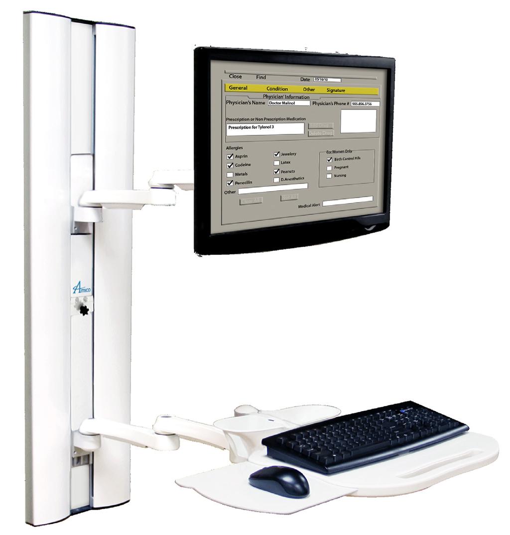
5 FEATURES Used for mounting monitors and keyboards on Amico SSM Arms to provide vertical adjustment Counter-balanced to provide ease of movement Mounting channel height adjustable up to 17 inches (43.18 cm) Concealed cable management Adjustable load range (10 to 30 lbs, 20 to 40 lbs) (4.5 to 13.6 kg, 9 to 18.1 kg) adjustment can be made at the top right corner. Ergonomic positioning options for the keyboard and monitor Lock mounting channel position by tightening Lock-knob (30.48cm) 1.13 (2.87cm) (33.79cm) (37.41cm) 7.93 (20.14cm) LOCK (71.95cm) (54.69cm) (54.61cm) Note: Mouse Tray 7 (17.78cm) When Extended (112.09cm) (89.23cm) (114.3cm) (43.18cm) Channel Adjustment Cable Management 48"(121.92cm) Clearance Needed for 12" Double Arm, KEYBRDF-SSM1 (Shown) 38" (96.52cm) Clearance Needed for 12" Single Arm, KEYBRDF-SSM0 28" (71.12cm) Clearance Needed for Flush Mount, KEYBRDF-SSM4 24" (60.96cm) Clearance Needed for Ultra Flush Mount, KEYBRD4-SSM4 32"(81.28cm) Clearance Needed for 12" Double Arm, SSM-LCD-15 (Shown) 22"(55.88cm) Clearance Needed for 12" Single Arm, SSM-LCD-05 12"(30.48cm) Clearance Needed for Flush Mount, SSM-LCD-45 12"(30.48cm) Clearance Needed for Ultra Flush Mount, SSM-LCD-F5 5
6 FEATURES (68.58cm) (W/O MONITOR) 27"(68.58cm) Clearance Needed for 12" Double Arm, SSM-LCD-15 (Shown) 17"(43.18cm) Clearance Needed for 12" Single Arm, SSM-LCD-05 7"(17.78cm) Clearance Needed for Flush Mount, SSM-LCD-45 5"(12.70cm) Clearance Needed for Ultra Flush Mount, SSM-LCD-F5 43"(109.22cm) Clearance Needed for 12" Double Arm, KEYBRDF-SSM1 (Shown) 33" (83.22cm) Clearance Needed for 12" Single Arm, KEYBRDF-SSM0 23" (58.42cm) Clearance Needed for Flush Mount, KEYBRDF-SSM4 17" (43.18cm) Clearance Needed for Ultra Flush Mount, KEYBRD4-SSM (5.08cm) 43 (109.22cm) 7"(17.78cm) Clearance Needed for 12" Double Arm, SSM-LCD-15 (Shown) 7"(17.78cm) Clearance Needed for 12" Single Arm, SSM-LCD-05 7"(17.78cm) Clearance Needed for Flush Mount, SSM-LCD-45 5"(12.70cm) Clearance Needed for Ultra Flush Mount, SSM-LCD-F (17.78cm) (W/O MONITOR) Distance from the wall changes depending on the CPU size (5.08cm) 31"(78.74cm) Clearance Needed for 12" Double Arm, KEYBRDF-SSM1 (Shown) 21"(53.34cm) Clearance Needed for 12" Single Arm, KEYBRDF-SSM0 11"(27.94cm) Clearance Needed for Flush Mount, KEYBRDF-SSM4 5"(12.70cm) Clearance Needed for Ultra Flush Mount, KEYBRD4-SSM (25.4cm) 6 Amico Accessories Inc.
7 SECTION 2: Installation Preparation Installation, Tools and Part requirements Tools required: Drill Drill bit size 9/64" (0.35 cm) Drill bit size ½"(1.27 cm) Philips screwdriver Allen Key size 5/32" (0.39 cm) Allen Key Size 1/8" (0.31cm) ½" Socket Wrench (1.27 cm) NOTE: Amico does not provide any monitor hardware, nor the tools necessary for assembly. Hardware required: 2 X Mounting channel stopper with screw, ½" (1.27 cm) (provided by Amico) Wall with studs/backing: 7 X Self drill screws, ¼-20, 3" (7.62 cm) (provided by Amico) Hollow wall: 7 X ¼ (0.635 cm)-20 x 2 ½ (6.35 cm) Flat head socket screws-fully threaded, 7 X Snap toggle wings Other Items Provided by Amico: Condor Channel Accessories, mounting adapters, and arms if purchased through Amico Accessories Inc. Pre-Installation Information (PLEASE READ CAREFULLY BEFORE STARTING) WARNING WARNING IT IS DANGEROUS TO USE THE CONDOR FOR WEIGHTS OUTSIDE OF THE RATED RANGE. STRUCTURAL FAILURE AND/OR SERIOUS INJURY COULD RESULT. DO NOT POSITION THE CONDOR ABOVE A PATIENT. The Condor contains a strong gas spring which is used to counter-balance the weight of the mounted device. The Condor housing should never be disassembled by non-amico personnel. Failure to follow these guidelines could result in serious injury. It shall be the responsibility of the hospital, its consultants and/or contractors to determine if the wall is adequate to safely mount the specific instrument. This includes the selection of appropriate fasteners and the proper installation, regardless of what is supplied with your Condor. Verify the weight of the device to be mounted. (Condors are rated for a maximum of 40 lbs (18.1 kg) or 30 lbs (13.6 kg), depending on the model you purchased). Check that the device to be mounted does not exceed the weight rating. Serious injury and damage to the Condor can occur as a result of overloading arm assembly. If you are unsure of your application, please contact an Amico Accessories product Specialist at Considerable efforts have been made to ensure the safety of your hospital staff and your patients. The installation itself is beyond the control of Amico Accessories Inc.. Accordingly, Amico Accessories Inc. will not be responsible for failure related to the installation of the product. CONTACT AMICO ACCESSORIES INC. TO DISCUSS SOLUTIONS NOT COVERED IN THIS MANUAL AT
 (68.58 cm) from floor, to provide a seated 28\" (71.")
8 SECTION 3: Installation on Wall Mounting Preparation The Condor comes with a set of channel covers. Remove the central channel cover to expose all 7 wall mounting holes. Gas Spring Cover Cable Management Channel Cover Location of top mounting hole Mount bottom of Condor Channel 27" (2 ¼ feet) (68.58 cm) from floor, to provide a seated 28" (71.12 cm) keyboard height to standing 45" (114.3 cm) keyboard height for a single SSM Arm. Mounting distance changes to 25" (63.5 cm) when using a keyboard tray with a double SSM Arm. Central Channel Cover Location of bottom mounting holes 2 ¼ feet (68.58 cm) Floor Mounting on wall with studs/backing: NOTE: Depending on whether a single or double SSM arm is used, the mounting height of the Condor Channel will change. This is because in a double SSM, the keyboard tray and monitor head is 2" (5.08 cm) higher due to the layering of the arms. 1. Locate and mark the top mounting hole at a distance of 69"/168 cm from the floor for a configuration using single SSM arms, and 71"/180 cm from the floor for a configuration using double SSM arms. 2. Drill a 9/64" (0.35 cm) diameter hole and secure one ¼ -20 x 2 ½ ( cm x 6.35 cm) tapping screws. 3. Hang the top mounting hole of the Condor (key-hole style) to this screw. 4. Mark remaining 6 holes as shown in Figure 2, checking to ensure Condor is plumb, flush and level. 5. Secure the Condor using remaining ¼ -20 x 2 ½" ( cm x 6.35 cm) tapping screws. 6. Correctly installed Condor should be flush against the wall and will not wobble side to side or up and down. If your Condor is behaving differently please contact an Amico Accessories Inc. Product Specialist at Amico Accessories Inc.
9 SECTION 3: Installation on Wall Mounting on hollow wall: 1. Locate and mark the top mounting hole at a distance of 69"/168 cm from the floor for a configuration using single SSM arms, and 71"/180 cm from the floor for a configuration using double SSM arms. 2. Use the Condor as a template to mark the remaining mounting holes, checking to ensure the Condor is kept plumb, flush and level. 3. Drill ½ inch holes at each marked position. 4. Install snap-toggles in all 7 holes: a. Hold snap-toggle metal channel flat alongside plastic straps and slide metal channel through hole. b. Hold both ends of plastic straps; pull toward you until channel rests flush behind wall. Slide plastic cap along straps with other hand until flange of cap is flush with wall. c. Snap the straps to break away at the plastic cap. 4. Hang the Condor on the top screw and secure with ¼ -20 x 2 ½" ( cm x 6.35 cm) flat head socket screw. 5. Secure remaining screws in holes. General instruction for opening and closing the Condor covers (Refer to Figure 3) The slotted edge is always closer to the mounting channel and the rounded edge is always outside as shown in figure 3. Both left and right covers are opened by inserting a flat-head screwdriver in the gap located along the mounting channel and levering up. While closing, first insert the slotted edge and squeeze-in the rounded edge on one end and follow towards the other end. Figure 3 Slotted edge Rounded edge 9


10 SECTION 4: EQUIPMENT INSTALLATION Equipment Mounting Recommendations The following mounting configurations are recommended for safe mounting on Condor Keyboard and Monitor Flush Monitor Flush and Keyboard with 9"/12" (22.86 cm/ cm) SSM Arm 10 Amico Accessories Inc.
 SSM Arm It is advised to mount CPU near top left of Condor; with power and data outlets close to CPU for convenience in cable management.")
11 SECTION 4: EQUIPMENT INSTALLATION Equipment Mounting Recommendations Monitor on 12" (30.48 cm) SSM Arm and Keyboard on 9" x 9" (22.86 cm x cm) SSM Arm Both Monitor and Keyboard on 9" x 9" (22.86 cm x cm) SSM Arm It is advised to mount CPU near top left of Condor; with power and data outlets close to CPU for convenience in cable management. Consider using USB cable extensions or a USB hub if necessary for keyboard, mouse and/or scanner cables. 11

12 MOUNTING OF ACCESSORIES Mounting of accessories to the mounting channel can be done by mounting the accessories to an adapter first. WARNING To prevent the adapter from sliding down the channel, ensure the four set screws are fastened to the tightest possible position, serious injuries could result if the set screws are not properly fastened. NOTE: Top and bottom stopper are there to prevent the adapter from sliding out of the MRS. The adapter must be taken out from the top of the rail with the top stopper pressed back into the rail 1. Install the adapter onto the accessory to be installed. Before installation, please determine the approximate position on the mounting channel that the accessory will be mounted. Remove both top and bottom Mounting Channel covers (Figure 4) Mounting Channel Mounting Channel Cover Figure 4 2. If the accessory is to be mounted in the upper half of the mounting channel, then guide the MON Adapter into the mounting channel from the top. For more detail, please see installation manual for accessory on how to mount to a MRS Rail. 3. If the accessory is to be mounted in the lower half of the mounting channel, first remove the mounting channel stoppers on the bottom of the mounting channel using a Phillips screwdriver (Figure 5). Then guide the MON Adapter into the mounting channel from the bottom. For more detail, please see installation manual for accessory on how to mount to a MRS Rail. 12 Amico Accessories Inc.
 hex key. 5.")
13 MOUNTING OF ACCESSORIES Mounting Channel Mounting Channel Stopper Figure 5 4. Once the accessory is at the desired height, tighten all four set screws to the tightest possible position on the adapter using 1/8" ( cm) hex key. 5. Re-install the mounting channel stoppers onto the mounting channel by attaching them to the two holes on the bottom of the channel (Figure 5). WARNING The channel stoppers will break if screw is over tightened. 6. Reinstall the mounting channel covers, trim off excess covers in order to fit them into the channel (Figure 4). 13
14 SECTION 5: Adjustments WARNING Do not over-rotate the counterbalance bolt. Once you feel resistance, stop. Forcing the bolt will damage the internals of the Condor and void the warranty. NOTE: Only adjust if necessary. Adjusting the Counterbalance 1. Once the Condor is securely installed, tighten the locking knob to lock the Condor. 2. To adjust for heavier loads, slowly loosen the counterbalance bolt rotating counter-clockwise, located on the top right corner of the Condor. To adjust for lighter loads, slowly tighten the counterbalance bolt, rotating clockwise using a ½" (1.27 cm) socket wrench. 3. Release the locking lever. If the arm has been correctly balanced, the arm will not drop or lift and it will remain in the same position. Ensure the arm is balanced from the lowest to the highest position by checking in various positions. 4. If arm is not correctly balanced, repeat from step 1. Adjusting Inter-Accessory Distance 1. Once the Condor is securely installed, tighten the locking knob to lock the Condor. 2. Loosen the set screws on the adapter holding the accessory that will be moved, using an Allen Key size 1/8" ( cm). 3. Holding the weight of the accessory, move it up and down in the channel until it reaches the desired position. 4. Tighten the set screws. 14 Amico Accessories Inc.
, maximum number of cables: 5 Cable Routing Procedure NOTE: All accessories should be mounted and properly positioned before cable management procedures. 1.")
15 SECTION 6: Cable Management Cable Requirement for CPU Mounting on Top Cable length minimum: 10 feet (304.8 cm), maximum number of cables: 5 Cable Routing Procedure NOTE: All accessories should be mounted and properly positioned before cable management procedures. 1. Release Condor Lock and bring Condor mounting channel to top most position and re-lock. 2. Open Condor left cover (Figure 3). 3. Remove both top and bottom Channel Covers as well as both cable clamps. 4. Take the cables from the monitor side (upper half) of the Mounting Channel and direct them into the space occupied by the Upper Cable clamp. 5. Install the Upper Cable clamp back into its original space and clamp over the cables going through it. Ensure the fit is tight and the cables cannot move around inside. 6. Do the same with cables coming from the keyboard tray side (lower half) of the Mounting Channel; make sure the cables are clamped tightly in the Cable clamps. 7. Leave 4-6 feet ( cm) of cables inside the left side cavity of the Condor for the cables to move around. Insert the rest of the cables through the top/bottom cap. Whether the cables exit from the top or bottom side of the Condor should depend on the positioning of the CPU in relation to the Condor. 8. Connect the cables to the CPU. 9. Replace the Channel Covers by sliding them into the Mounting Channel, covering up the cables. Trim off any excess Channel Covers. 10. Replace the left Condor cover. Cable Opening Upper Cable clamp Lower Cable clamp Cable Figure
16 SECTION 7: Maintenance, Troubleshooting and Product Classification Troubleshooting Condor Mounting Channel is Drifting Upwards or Downwards Counter-balancing mechanism is not set appropriately for the given load. Counter-balancing mechanism can be corrected by tightening or loosening the screw embedded inside the top right corner of the Condor. Turn clockwise for lighter loads and counter-clockwise for heavier loads. If Condor is still not counter balanced at the limit of the adjustable range, contact Amico Accessories for a replacement gas spring. Condor Mounting Channel is Not Drifting, But is Too Hard to Move Up/Down Counter-balancing mechanism is not set appropriately for the given load. Counter-balancing mechanism can be corrected by tightening or loosening the screw embedded inside the top right corner of the Condor. Turn clockwise for lighter loads and counter-clockwise for heavier loads. If Condor is still not counter balanced at the limit of the adjustable range, contact Amico Accessories for a replacement gas spring. Loud/Unnatural Noise When Moving the Channel This indicates that the internals are damaged, please move the channel to the lowest position, engage the lock, and contact Amico Accessories. There is Debris on the Bottom of the Condor or on the Ground Beneath the Condor This indicates that there is grinding or scraping of the internals, please move the channel to the lowest position, engage the lock, and contact Amico Accessories. 16 Amico Accessories Inc.
17 SECTION 7: Maintenance, Troubleshooting and Product Classification Preventative Maintenance WARNING The Condor requires periodic inspection and maintenance to perform optimally and achieve maximum operation life. The intervals shown below are recommended. Maintenance schedules should be shortened for Condors that see heavy use. NOTE: Please follow the Preventative maintenance protocol for the accessories as stated in the manual for those accessories. Please be sure to thoroughly check the areas illustrated below for Condors. Area 1: Mounting Channel and Track System a. Visually inspect for any signs of grinding and gapping along the sides of the channel. b. Check if the accessories are mounted properly and tightly to the channel. c. Remove the MRS cover and ensure that the cables are staying inside the tracks and are not tangled. Area 2: Cable Management Clamps a. Visually inspect for any signs of grinding by checking for debris around the part. b. Make sure the screws are tightly installed and the cables are clamped down properly. Area 3: Cable Management Side a. Remove cover and check if there is grinding or tangling of cables inside. Area 4: Force Adjuster Side a. Visually inspect for any signs of grinding and gapping on the pulleys as well as on the side of extrusions. b. Pulleys: Ensure the screws holding the pulleys are fastened tightly. c. Spring: Visually inspect the spring to see if there has been any damage to the outer shell. d. Threaded rod: check for bending and damage to the threads. 17

 from wall AHC-1-L0-K0-C2 Includes flush LCD SSM arm provides tilt and swivel Includes 12\" (30.")
 from wall Keyboard extends 33\" (83.")
 from wall Keyboard extends 43\" (109.22 cm) from wall AHC-1-L1-K1-C2 Includes 12\" (30.")
 from wall, LCD extends 17\" (43.18 cm) from wall AHC-1-LF-KF-C2 Includes 12\" (30.")
 from wall Keyboard extends 43\" (109.22 cm) from wall, LCD extends 17\" (43.")
 from wall, LCD extends 27\" (68.")
 from the wall Keyboard extends 17\" (43.18 cm) from wall 18 Amico Accessories Inc.")

 from wall Keyboard extends 43\" (109.22 cm) from wall")
18 PRODUCT CLASSIFICATION AHC-1-L4-K4-C2 AHC-1-L4-K0-C2 AHC-1-L4-K1-C2 Includes flush LCD SSM arm provides tilt and swivel Includes flush keyboard SSM arm provides swivel and negative tilt Folds to less than 10" (25.4 cm) from wall Keyboard extends 23" (58.42 cm) from wall AHC-1-L0-K0-C2 Includes flush LCD SSM arm provides tilt and swivel Includes 12" (30.48 cm) keyboard SSM arm provides swivel, articulation and negative tilt Folds to less than 10" (25.4 cm) from wall Keyboard extends 33" (83.82 cm) from wall AHC-1-L0-K1-C2 Includes flush LCD SSM arm provides tilt and swivel Includes 12"x12" (30.48 cm x cm) keyboard SSM arm provides swivel, articulation and negative tilt Folds to less than 10" (25.4 cm) from wall Keyboard extends 43" ( cm) from wall AHC-1-L1-K1-C2 Includes 12" (30.48 cm) LCD SSM arm provides tilt, articulation and swivel Includes 12" (30.48 cm) keyboard SSM arm provides swivel, articulation and negative tilt Folds to less than 10" (25.4 cm)from wall Keyboard extends 33" (83.82 cm) from wall, LCD extends 17" (43.18 cm) from wall AHC-1-LF-KF-C2 Includes 12" (30.48 cm) LCD SSM arm provides tilt, articulation and swivel Includes 12"x12" (30.48 cm x cm) keyboard SSM arm provides swivel, articulation and negative tilt Folds to less than 10" (25.4 cm) from wall Keyboard extends 43" ( cm) from wall, LCD extends 17" (43.18 cm) from wall AHC-1-LD-K4-C2 Includes 12"x12" (30.48 cm x cm) LCD SSM arm provides tilt, articulation and swivel Includes 12"x12" (30.48 cm x cm) keyboard SSM arm provides swivel, articulation and negative tilt Folds to less than 10" (25.4 cm) from wall Keyboard extends 43" ( cm) from wall, LCD extends 27" (68.58 cm) from wall AHC-1-LD-K3-C2 Includes ultra flush LCD mount Includes ultra flush keyboard SSM arm provides negative tilt Folds less than 5" (12.7 cm) from the wall Keyboard extends 17" (43.18 cm) from wall 18 Amico Accessories Inc. Includes dual screen mount provides tilt, swivel and articulation for both monitors Includes flush keyboard SSM arm provides swivel and negative tilt Folds to less than 10" (25.4 cm) from wall Keyboard extends 23" (58.42 cm) from wall Includes dual screen mount provides tilt, swivel and articulation for both monitors Includes 12"x12" (30.48 cm x cm) keyboard SSM arm provides swivel and negative tilt Folds to less than 10" (25.4 cm) from wall Keyboard extends 43" ( cm) from wall
19 CLEANING WARNING The cleaning chemicals and methods below are not meant for controlling any infections. It shall be the responsibility of the hospital or the hospital s infection control officer to sanitize the equipment. WARNING Please do not spray any chemical directly onto the arm. Apply onto a soft cloth and wipe clean to prevent chemicals getting into the internal components of the arm. The mounting assembly may be cleaned with most mild, non-abrasive solutions commonly used in the hospital environment (e.g. diluted bleach, ammonia, or alcohol solutions). No Acetone. No Trichloroethylene. The surface finish will be permanently damaged by strong chemical and solvent such as acetone and trichloroethylene. Steel wool or other abrasive material should never be used. Damage caused by the use of unapproved substances or processes will not be warranted. It is recommended that you test any cleaning solution on a small area of the Condor that is not visible to verify compatibility. Never submerge the Condor and do not allow liquids to enter it. Wipe any cleaning agents off the Condor immediately using a water-dampened cloth. Dry the arm thoroughly after. 19
20 Amico Accessories Inc Fulton Way, Richmond Hill Ontario, L4B 2N4, Canada 71 East Industry Court, Deer Park NY 11729, U.S.A Toll Free Tel: Toll Free Fax: Tel: Fax: ACC CONDOR MANUAL
Installation Instructions. ARS (Amico Rail Systems)
") Installation Instructions ARS (Amico Rail Systems) w w w. a m i c o. c o m Preface Important, Please Read Carefully Thank you for your purchase with Amico Accessories Inc. This unit is designed for long
Installation Instructions ARS (Amico Rail Systems) w w w. a m i c o. c o m Preface Important, Please Read Carefully Thank you for your purchase with Amico Accessories Inc. This unit is designed for long
Installation Guide VHM Wall Mount Kit for Philips MX600/700/800 and MP60/70 IntelliVue
 Installation Guide VHM Wall Mount Kit for Philips MX600/700/800 and MP60/70 IntelliVue The purpose of this guide is to: 1. Describe attachment of Table Top Mount to Mounting Adapter (page 2). 2. Describe
Installation Guide. Philips MP20/30/40/50 IntelliVue VHM Wall Mount Kit
 Installation Guide Philips MP20/30/40/50 IntelliVue VHM Wall Mount Kit The purpose of this guide is to: 1. Describe attachment of Table Top Mount to Mounting Adapter. 2. Describe attachment of Mounting
Installation Guide VHM Arm Kit for Philips Heartstart MRx and Heartstart XL+
 Installation Guide VHM Arm Kit for Philips Heartstart MRx and Heartstart XL+ The purpose of this guide is to: 1. Describe installation of Arm in channel (page 2). 2. Describe mounting of defibrillator
3875 Cypress Drive Petaluma, CA Fax
 3875 Cypress Drive Petaluma, CA 94954 800.228.2555 +1.707.773.1100 Fax 707.773.1180 www.gcx.com VHM-P (Non-Locking) Variable Height Arm with Fixed Angle Front End for Flat Panel / Keyboard Bracket (L Brackets
VHM-P (Non-Locking) and VHM-PL (Locking) Variable Height Arm with Slide-In Mounting Plate
 and VHM-PL (Locking) Variable Height Arm with Slide-In Mounting Plate") 3875 Cypress Drive Petaluma, CA 94954 800.228.2555 +1.707.773.1100 Fax 707.773.1180 www.gcx.com VHM-P (Non-Locking) and VHM-PL (Locking) Variable Height Arm with Slide-In Mounting Plate (Refer to qualified
3875 Cypress Drive Petaluma, CA 94954 800.228.2555 +1.707.773.1100 Fax 707.773.1180 www.gcx.com VHM-P (Non-Locking) and VHM-PL (Locking) Variable Height Arm with Slide-In Mounting Plate (Refer to qualified
GCX Mounting Assembly Installation Guide. Philips MP90 (M8010A) Mounting Kit for Drager Zeus
 Mounting Kit for Drager Zeus") GCX Mounting Assembly Installation Guide Philips MP90 (M8010A) Mounting Kit for Drager Zeus The purpose of this guide is to: 1. Describe attachment of Down Post to Arm. 2. Describe attachment of Arm to
GCX Mounting Assembly Installation Guide Philips MP90 (M8010A) Mounting Kit for Drager Zeus The purpose of this guide is to: 1. Describe attachment of Down Post to Arm. 2. Describe attachment of Arm to
Installation Manual for Philips Intellivue MP5/20/30 VHM-25 Channel Mount Kit
 3875 Cypress Drive Petaluma, CA 94954 800.228.2555 707.773.1100 Fax 707.773.1180 www.gcx.com Installation Manual for Philips Intellivue MP5/20/30 VHM-25 Channel Mount Kit Install Time: 10-15 minutes The
Installation Manual for Philips SureSigns VS3/VS4/VM4/VM6/VM8/VSV VHM-25 Countertop Mount
 3875 Cypress Drive Petaluma, CA 94954 800.228.2555 707.773.1100 Fax 707.773.1180 www.gcx.com Installation Manual for Philips SureSigns VS3/VS4/VM4/VM6/VM8/VSV VHM-25 Countertop Mount Install Time: 20-30
Installation Guide Philips MP2 IntelliVue M-Series Arm (12'' or 8'') Rail Mount Kit
 Rail Mount Kit") Installation Guide Philips MP2 IntelliVue M-Series Arm (12'' or 8'') Rail Mount Kit The purpose of this guide is to: 1. Describe mounting of MP2 equipment on Mounting Bracket (page 2). 2. Describe mounting
Installation Guide Philips MP2 IntelliVue M-Series Arm (12'' or 8'') Rail Mount Kit The purpose of this guide is to: 1. Describe mounting of MP2 equipment on Mounting Bracket (page 2). 2. Describe mounting
VHM-P (Non-Locking) Variable Height Arm with VESA Mounting Plate for 75 x 75mm or 100 x 100mm applications
 Variable Height Arm with VESA Mounting Plate for 75 x 75mm or 100 x 100mm applications") 3875 Cypress Drive Petaluma, CA 94954 800.228.2555 +1.707.773.1100 Fax 707.773.1180 www.gcx.com VHM-P (Non-Locking) Variable Height Arm with VESA Mounting Plate for 75 x 75mm or 100 x 100mm applications
3875 Cypress Drive Petaluma, CA 94954 800.228.2555 +1.707.773.1100 Fax 707.773.1180 www.gcx.com VHM-P (Non-Locking) Variable Height Arm with VESA Mounting Plate for 75 x 75mm or 100 x 100mm applications
Installation Guide. Philips IntelliVue MP20/30/40/50/60/70, MX400/450/600/700/800 Low Profile Camlock Mount
 Installation Guide Philips IntelliVue MP20/30/40/50/60/70, MX400/450/600/700/800 Low Profile Camlock Mount The purpose of this guide is to: 1. Describe mounting of Philips Table Top Mount on Table Top
Installation Guide Stack Mount Kit for Philips G5 and MP5/20/30/40/50/60/70 Monitor
 Installation Guide Stack Mount Kit for Philips G5 and MP5/20/30/40/50/60/70 Monitor The purpose of this guide is to describe installation of the Stack Mount. Parts Reference The following parts and hardware
(Refer to qualified personnel)
") 3875 Cypress Drive Petaluma, CA 94954 800.228.2555 +1.707.773.1100 Fax 707.773.1180 www.gcx.com Installation Guide VHM-P (Non-Locking) and VHM-PL (Locking) Variable Height Arm (Slide-Above-Arm Configuration)
3875 Cypress Drive Petaluma, CA 94954 800.228.2555 +1.707.773.1100 Fax 707.773.1180 www.gcx.com Installation Guide VHM-P (Non-Locking) and VHM-PL (Locking) Variable Height Arm (Slide-Above-Arm Configuration)
Installation Manual for VHM-25 Series Arms Channel Mount
 3875 Cypress Drive Petaluma, CA 94954 800.228.2555 707.773.1100 Fax 707.773.1180 www.gcx.com Installation Manual for VHM25 Series Arms Channel Mount Install Time: 1015 minutes The purpose of this manual
GCX Mounting Assembly Operation/Installation Manual
 GCX Mounting Assembly Operation/Installation Manual Dräger Model Fabius GS with Dräger Vamos, CWS 15 "Recall" and GEMS IT DASH 3000/4000 Patient Monitor Option 1 Option 2 Option 3 Vamos or Dash 3000/4000
Installation Guide GE Healthcare Carescape Single Display Roll Stand Kit
 Installation Guide GE Healthcare Carescape Single Display Roll Stand Kit The purpose of this guide is to describe assembly of the Roll Stand. WARNING - EXCESSIVE LEAKAGE CURRENT - DO NOT use multiple socket
Installation Guide Philips MP90 Dual Display Mounting Kit for Dräger Apollo Anesthesia Machine
 Installation Guide Philips MP90 Dual Display Mounting Kit for Dräger Apollo Anesthesia Machine The purpose of this guide is to describe installation of the Mounting Kit on the anesthesia machine. Parts
Installation Guide Roll Stand Kit for Philips MP20/30 Monitor
 Installation Guide Roll Stand Kit for Philips MP20/30 Monitor The purpose of this guide is to: 1. Describe attachment of Post to Base (page 2). 2. Describe attachment of the Utility Basket to the Roll
Installation Guide GE Healthcare Carescape Dual Display Roll Stand Kit
 Installation Guide GE Healthcare Carescape Dual Display Roll Stand Kit The purpose of this guide is to describe assembly of the Roll Stand. WARNING - EXCESSIVE LEAKAGE CURRENT - DO NOT use multiple socket
Installation Guide Folding L-Bracket with Display Mounting Extension and Keyboard Tray for M-Series or VHM Arm
 3875 Cypress Drive Petaluma, CA 94954 800.228.2555 707.773.1100 Fax 707.773.1180 www.gcx.com Installation Guide Folding L-Bracket with Display Mounting Extension and Keyboard Tray for M-Series or VHM Arm
Installation Guide Roll Stand Kit 2''/5.1cm Diameter Post with Tilt/Swivel Mounting Plate, Handle, Utility Basket and 10lbs/4.
 3875 Cypress Drive Petaluma, CA 94954 800.228.2555 707.773.1100 Fax 707.773.1180 www.gcx.com Installation Guide Roll Stand Kit 2''/5.1cm Diameter Post with Tilt/Swivel Mounting Plate, Handle, Utility Basket
GE CARESCAPE Monitor B650 on VHM- PL Variable Height Arm Channel Mount with Vertical Position Lock
 GE CARESCAPE Monitor B650 on VHM- PL Variable Height Arm Channel Mount with Vertical Position Lock PRODUCT DETAILS VHM-PL (Locking) Variable Height Arm with 14" / 35.6 cm Extension and Slide-In Mounting
Installation Guide. Xprezzon Roll Stand
 3875 Cypress Drive Petaluma, CA 94954 800.228.2555 707.773.1100 Fax 707.773.1180 www.gcx.com Installation Guide Xprezzon Roll Stand The purpose of this guide is to describe assembly of the Roll Stand and
Installation Guide Philips MP90 Mounting Kit with 16'' M-Series Arm for Datex Ohmeda Avance Anesthesia Machine
 Installation Guide Philips MP90 Mounting Kit with 16'' M-Series Arm for Datex Ohmeda Avance Anesthesia Machine The purpose of this guide is to describe installation of the Mounting Kit on the anesthesia
Installation Guide Variable Height Roll Cart for Corometrics/GE 250 Series Fetal Monitor with Dual Displays and Keyboard Mounts
 3875 Cypress Drive Petaluma, CA 94954 800.228.2555 707.773.1100 Fax 707.773.1180 www.gcx.com Installation Guide Variable Height Roll Cart for Corometrics/GE 250 Series Fetal Monitor with Dual Displays
Installation Guide Corometrics/GE 250 Series Fetal Monitor Roll Cart with Laptop and Display Mounts
 3875 Cypress Drive Petaluma, CA 94954 800.228.2555 707.773.1100 Fax 707.773.1180 www.gcx.com Installation Guide Corometrics/GE 250 Series Fetal Monitor Roll Cart with Laptop and Display Mounts Table of
Installation Guide GE Mini Telemetry Receiver Rear Column Mount
 3875 Cypress Drive Petaluma, CA 94954 800.228.2555 707.773.1100 Fax 707.773.1180 www.gcx.com Installation Guide GE Mini Telemetry Receiver Rear Column Mount Parts Reference The following parts and hardware
Installation Guide LiDCO Hemodynamic Monitor - Roll Stand Kit (US Version)
") Installation Guide LiDCO Hemodynamic Monitor - Roll Stand Kit (US Version) The purpose of this guide is to describe assembly of the roll stand kit and mounting of applicable devices. Table of Contents.0
Installation Guide LiDCO Hemodynamic Monitor - Roll Stand Kit (US Version) The purpose of this guide is to describe assembly of the roll stand kit and mounting of applicable devices. Table of Contents.0
Installation Guide LiDCO Hemodynamic Monitor - Roll Stand Kit (EURO Version)
") Installation Guide LiDCO Hemodynamic Monitor - Roll Stand Kit (EURO Version) The purpose of this guide is to describe assembly of the roll stand kit and mounting of applicable devices. Table of Contents.0
Installation Guide LiDCO Hemodynamic Monitor - Roll Stand Kit (EURO Version) The purpose of this guide is to describe assembly of the roll stand kit and mounting of applicable devices. Table of Contents.0
FOR SIT-STAND WORKSTATION
 INSTALLATION MANUAL FOR SIT-STAND WORKSTATION Weight Capacity: 6.5-24.5 lbs. 6017180 Rev. B Contents Tools Required / Supplied Part Kits / Warnings/Disclaimers...2 Base Installation Clamp Mount Base Location...3
FOR WALL MOUNT COMBINATION ARMS
 INSTALLATION MANUAL FOR WALL MOUNT COMBINATION ARMS LIGHT DUTY ARMS HEAVY DUTY ARMS KEYBOARD TRAY VERSION Weight Capacity 4-20 lbs KEYBOARD TRAY VERSION Weight Capacity 8-40 lbs WORKSTATION VERSION Weight
GAS CYLINDER LIFTS BEFORE YOU BEGIN
 I N S T R U C T I O N M A N U A L GAS CYLINDER LIFTS The LM Series gas cylinder lifts are smooth, quiet reliable lift mechanisms for your valuable equipment in a mobile application. The LM Series can be
S-Drive Performance Trainer
 S-Drive Performance Trainer SERVICE MANUAl Table of contents CHAPTER 1: Serial number location... 1 CHAPTER 2: Important Safety instructions 2.1 Read and Save These Instructions... 2 2.2 Before Getting
A B C D E F. Tools Required (supplied by others)
") Page 1 of 17 Parts List Below Deck Automatic Retractable Security Cover Kit (1) Tube End Bearing Plate (A) (1) Rope Reel and Cover Drum Motor Assembly (B) (1) Cover Drum (1) Pulley Support Channel (2)
Page 1 of 17 Parts List Below Deck Automatic Retractable Security Cover Kit (1) Tube End Bearing Plate (A) (1) Rope Reel and Cover Drum Motor Assembly (B) (1) Cover Drum (1) Pulley Support Channel (2)
A B C D E F. b.tools Required (supplied by others) 3/16" Drill Bit 3/8" Wrench Phillips Head Screwdriver
 3/16 Drill Bit 3/8 Wrench Phillips Head Screwdriver") Page 1 of 13 5E.1 Parts List a. Below Deck Automatic Retractable Security Cover Kit (1) Tube End Bearing Plate (A) (1) Rope Reel with Motor Attached (B) (1) Rope Reel Cover (C) (1) Cover Drum (1) Cover
Page 1 of 13 5E.1 Parts List a. Below Deck Automatic Retractable Security Cover Kit (1) Tube End Bearing Plate (A) (1) Rope Reel with Motor Attached (B) (1) Rope Reel Cover (C) (1) Cover Drum (1) Cover
Checker Unload Checkstand Installation Instructions
 Front-End Checkouts Commercial Refrigeration Equipment Display Merchandisers Store Fixtures Checker Unload Checkstand Installation Instructions Attention Store Manager: Please find enclosed in this packet
OWNER S MANUAL QUESTIONS? CAUTION. Model No. F811.0 Serial No. Write the serial number in the space above for reference. Serial Number Decal
 Model No. F811.0 Serial No. Write the serial number in the space above for reference. OWNER S MANUAL Serial Number Decal QUESTIONS? If you have questions, or if parts are damaged or missing, please see
3" & 4" Cast Iron Self-Priming Centrifugal Pump Instruction Manual
 12 3" & 4" Cast Iron Self-Priming Centrifugal Pump Instruction Manual 333 & 444 Series Read these instructions and the instructions covering operation of the pump drive unit. Do not operate the gas engine
INSTALLATION MANUAL FOR PILOT WORKSTATION
 INSTALLATION MANUAL FOR PILOT WORKSTATION Weight Capacity: 5-25 lbs. Monitor Weight: 5-20 lbs. 6011180 Rev. B Contents Tools Required / Supplied Part Kits / Warnings/Disclaimer...2 Possible Base Mounting
Installation Instructions Z-Gate Shifter
 Installation Instructions Z-Gate Shifter Part Number 80681 1998, 2001 by B&M Racing and Performance Products The B&M Z-Gate shifter can be used in vehicles equipped with most popular three speed automatic
Installation Instructions. QuickSilver Shifter. Fits: GM, Ford, Chrysler Transmissions See Application Guide for Specific Applications Part # 80683
 Installation Instructions QuickSilver Shifter Fits: GM, Ford, Chrysler Transmissions See Application Guide for Specific Applications Part # 80683 WORK SAFELY! For maximum safety, perform this installation
Loose Components. VetPro 5000 Wall / Cabinet Mount Installation. Applies to Models:
 VetPro 5000 Wall / Cabinet Mount Installation warning Equipment not suitable for use in the presence of a flammable anesthetic mixture. Applies to Models: 8001-001 8001-002 8001-005 8001-006 Loose Components
Chrysler 727, 904, 518 Floor Mount Automatic Transmission Shifter Installation Instructions
 Chrysler 727, 904, 518 Mount Automatic Transmission Shifter Installation Instructions Building American Quality With A Lifetime Warranty! TOLL FREE 1-877-469-7440 tech@lokar.com www.lokar.com Release Button
Installation Instructions I - Sheet Number I-TVR-01 Rev. A
 Installation Instructions I - Sheet Number I-TVR-01 Rev. A TrailView Soft Top For proper installation and best possible fit, please read all instructions BEFORE you begin. For technical assistance or to
3.25 Ton Heavy Duty Floor Jack
 Please dispose of packaging for the product in a responsible manner. It is suitable for recycling. Help to protect the environment, take the packaging to the local amenity tip and place into the appropriate
xtablet T7000 Vehicle Mount Kit
 xtablet T7000 Vehicle Mount Kit Installation & Users Guide Last Updated: January 19, 2012 Find the latest updates in the Support section in the MobileDemand website at: www.ruggedtabletpc.com. Questions?
On-A-Roll Lifter Instruction Manual for Standard Models Read Before Use!
 On-A-Roll Lifter Instruction Manual for Standard Models Read Before Use! Important instructional, safety and precautionary information! It is the user s responsibility to exercise good judgment, common
INSTALLATION INSTRUCTIONS FOR THE MOTOR TRIKE GL1500 RAKE KIT
 INSTALLATION INSTRUCTIONS FOR THE MOTOR TRIKE GL1500 RAKE KIT Thank you for choosing the Motor Trike GL1500 Rake Kit. We ask that you read the directions before you start and follow them very closely.
GM Floor Mount Automatic Transmission Shifter Installation Instructions
 GM Mount Automatic Transmission Shifter Installation Instructions Building American Quality With A Lifetime Warranty! TOLL FREE 1-877-469-7440 tech@lokar.com www.lokar.com GM Mount Automatic Transmission
Motion System Components Diagram. Note: #2 Mirror Cover and X-Axis Motor Cover have been removed for visibility. Maintenance.
 Professional Laser System PLS3.75, PLS4.75, PLS6.75 and PLS6.150D Keeping the laser system clean will ensure the highest quality engraving. A clean laser system is the best performing laser system. The
Installation Instructions
 Installation Instructions TrailView Soft Top Important Safety Information For proper installation and best possible fit, please read all instructions BEFORE you begin. Periodically check all components
FlexJet - Flex Cable Replacement
 P/N: 109515R0 14140 NE 200th St. Woodinville, WA. 98072 PH: (425) 398-8282 FX: (425) 398-8383 FlexJet - Flex Cable Replacement Notices: Warning! Ensure that all AC power cables are removed from the printer
AIM LED LIGHT (wall mount)
") AIM LED LIGHT (wall mount) Installation Manual AIM LED LIGHT (wall mount) INTRODUCTION Lights in the AIM Series are designed to give the professional health care market superior performance, reliability
AIM LED LIGHT (wall mount) Installation Manual AIM LED LIGHT (wall mount) INTRODUCTION Lights in the AIM Series are designed to give the professional health care market superior performance, reliability
C15C C15C. Page 1 of 20
 2 x Lid Front Hinge 1135 8 x M8 Bolt 8 x M8 Washer (3mm Thick) 4 x M6 Large washers 4 x M6 Spring washers 4 x M6 x 40mm Bolts 6 x M6 20mm Bolts 6 x M6 Washers 20 x Screws 2 x Lid mount gas strut bracket
Models: 8500, 8501, 8513, 8514, 8500BL, 8501BL, 8513BL, 8514BL, 8540, 8541, 8550, 8551, 8540BL, 8541BL, 8550BL & 8551BL
 Standard Pump Ultra Mass High Viscosity Batch Control System Description Standard s Drum Pumps are designed to transfer a variety of materials from 55 gallon drums and tanks. Standard Pump offers several
3 Ton Trolley Jack. Please read and fully understand the instructions in this manual before operation. Keep this manual safe for future reference.
 Please dispose of packaging for the product in a responsible manner. It is suitable for recycling. Help to protect the environment, take the packaging to the local amenity tip and place into the appropriate
Operator's Manual. Storage System. Ultrasound Probe Cabinet. Manufactured by:
 Storage System Ultrasound Probe Cabinet Operator's Manual Manufactured by: CIVCO Medical Solutions 102 First Street South Kalona, IA 52247 USA 319.248.6757 / 800.445.6741 WWW.CIVCO.COM Copyright 2018 All
Ford C4 and C6 Floor Mount Automatic Transmission Shifter Installation Instructions
 Ford C4 and C6 Mount Automatic Transmission Shifter Installation Instructions Building American Quality With A Lifetime Warranty! TOLL FREE 1-877-469-7440 tech@lokar.com www.lokar.com Ford C4 and C6 Mount
PFadvantage MF 6850/6855; Ideal 9080/9090
 MF 6850/6855; Ideal 9080/9090 Note: Indented items indicate parts included in an Quantity by Model assembly listed above MF Ideal Part Name/Description Part Number 6850 6855 9080 9090 Instruction Kit MF
ASSEMBLY INSTRUCTIONS / OWNERS MANUAL AIR BIKE AB-1
 AIR BIKE AB- ASSEMBLY INSTRUCTIONS / OWNERS MANUAL IMPORTANT : READ ALL ASSEMBLY INSTRUCTIONS AND SAFETY PRECAUTIONS BEFORE USING THIS PRODUCT. REFERENCE ALL SAFETY GUIDELINES AND WARNING LABELS. RETAIN
Rollstar Shade Installation Instructions
 Rollstar Shade Installation Instructions All Lifting Systems Inside or Outside Mount Thank you for purchasing your new Rollstar shade. It has been custom-made from the highest quality materials to the
OWNERS MANUAL. ULTRA Single-Station Strength G7-S13 Chest Press
 OWNERS MANUAL ULTRA Single-Station Strength G7-S13 Chest Press Table Of Contents Safety, General Care & Maintenence...3 Getting Started (Product Specifications)...5 Assembly Information...6 Markings...7
OWNERS MANUAL. ULTRA Single-Station Strength G7-S42 Triceps Press
 OWNERS MANUAL ULTRA Single-Station Strength G7-S42 Triceps Press Table Of Contents Safety, General Care & Maintenence... 3 Getting Started (Product Specifications)... 5 Assembly Information... 6 Parts
INSTALLATION INSTRUCTIONS RATTLER STEEL RUNNING BOARDS FORD TRANSIT VAN (FULL SIZE)
") INSTALLATION INSTRUCTIONS PARTS LIST: 1 32-inch Steel Running Board 1 8-1.25mm x 35mm Hex Bolt 1 96-inch Steel Running Board 13 8-1.25mm x 25mm Hex Bolt 5 Passenger Side/Driver Side Mounting Brackets 20
INSTALLATION INSTRUCTIONS PARTS LIST: 1 32-inch Steel Running Board 1 8-1.25mm x 35mm Hex Bolt 1 96-inch Steel Running Board 13 8-1.25mm x 25mm Hex Bolt 5 Passenger Side/Driver Side Mounting Brackets 20
Installation Instructions
 COLONY/COLONY SOFT Bidet Faucet and Transfer Valve with Speed Connect Drain Congratulations on purchasing your American Standard faucet with the Speed Connect drain, a feature found only on American Standard
SCAMP AND UTILITY MODELS SELF-PROPELLED BELT DRIVE SERVICING 4502, 4503, 8602, 8603 WITH F SERIES ENGINES
 4502, 4503, 8602, 8603 WITH F SERIES ENGINES Adjustments and servicing of the Scamp and Utility self-propelled mowers are very different from all previous models of self-propelled mowers. BEFORE ANY ADJUSTMENTS
15,000kg HYDRAULIC BOTTLE JACK
 Product Code: 2013 OWNER S MANUAL PRODUCT CODE: 2013 15,000kg HYDRAULIC BOTTLE JACK Lifting Capacity 15,000kg Max. Lifting Height 447mm Min. Lifting Height 227mm Hydraulic Lift 125mm Screw Adjustment 70mm
OWNERS MANUAL. ULTRA Single-Station Strength G7-S34 Seated Row
 OWNERS MANUAL ULTRA Single-Station Strength G7-S34 Seated Row Table Of Contents Safety, General Care & Maintenence...3 Getting Started (Product Specifications)...5 Assembly Information...6 Markings...7
LGT-306L / LB Club Car Precedent LED Light Bar Bumper Kit Installation Instructions
 LGT-306L / LB Club Car Precedent LED Light Bar Bumper Kit Installation Instructions Caution: Please read through the instructions carefully. Before starting this project, remove the system s positive and
Installation Instructions Studio Makeup Station
 Installation Instructions Studio Makeup Station 30" and 36" Models 5-light 30" Studio Makeup Station 8-light 30" Studio Makeup Station 6-light 36" Studio Makeup Station 9-light 36" Studio Makeup Station
RETRACTABLE CEILING COLUMN
 RETRACTABLE CEILING COLUMN Installation Manual RETRACTABLE CEILING COLUMN INTRODUCTION Location, sequence of services and orientation of Surgical Ceiling Columns are specified on the building plans. Be
Compact Easy Rollator M66739
 User Instructions Compact Easy Rollator M66739 Maximum Safe Working Load 21st 135kg Please ensure these Instructions are fully read and understood before using this equipment. Retain these instructions
HAPPY TRAILS NO-ZIP PET STROLLER
 For The ON-THE-GO Pet INSTRUCTION MANUAL HAPPY TRAILS NO-ZIP PET STROLLER PG8100NZ Interior Dimensions: 24.5"L x 12"W x 21"H To see our full line of products, visit us online at: www.petgearinc.com CUSTOMER
WARNING: Only perform this installation if you are experienced, fully equipped mechanic.
 DYNATRAC V3.2 2005-Present Ford Super Duty 250/350-4x4, Front Axle, Free Spin Conversion Kit Some of the less common tools, which will be required: 6 point Spanner socket (OTC #7090-A or equivalent). These
D40C HINGE # x Support Plate x M8 Bolt 8 x M8 Washer 6 x M6 20mm Bolts 6 x M6 Washers 19 x Screws
 HINGE # 1017 2 x Support Plate 1018 8 x M8 Bolt 8 x M8 Washer 6 x M6 20mm Bolts 6 x M6 Washers 19 x Screws 2 x Lid mount gas strut bracket 1041 2 x Self tap strut mount 1040 1 x Central Lock bracket 1510
SPECIFICATIONS CONTENTS: Specifications Warning Information. Operating Instructions Preventative Maintenance Troubleshooting
 Model 3182 2,500 Lbs Power Train Table/Lift OWNER'S MANUAL CONTENTS: Page 1 Page 2-3 Page 3 Page 4 Page 5 Page 5 Page 6 Page 7 Page 8 Specifications Warning Information Setup Operating Instructions Preventative
Lexus ES Fine Mesh and Adaptive Cruise Control Fine Mesh Grilles Upper and Lower Replacements
 IMPORTANT: PLEASE KEEP THIS INSTRUCTION MANUAL FOR FUTURE REFERENCE! 2013-15 Lexus ES Fine Mesh and Adaptive Cruise Control Fine Mesh Grilles Upper and Lower Replacements Part #1372-0102-13 / Black Ice
**DO NOT EXCEED RECOMMENDED VEHICLE TOWING WEIGHT!**
 60648 SUBKIT 9/8/015 **DO NOT EXCEED RECOMMENDED VEHICLE TOWING WEIGHT!** PAGE 1 OF 5 WARNING!! BRAKE, FUEL, AND ELECTRICAL LINES MAY NEED TO BE LOOSENED OR REPOSITIONED TO PROVIDE CLEARANCE FOR NEW HARDWARE.
Brake System H TX, H2.0TXS [B475]; H TX [B466] Safety Precautions Maintenance and Repair
![Brake System H TX, H2.0TXS [B475]; H TX [B466] Safety Precautions Maintenance and Repair](/thumbs/86/93834005.jpg "Brake System H TX, H2.0TXS [B475]; H TX [B466] Safety Precautions Maintenance and Repair") HMM180001 Brake System H1.5-1.8TX, H2.0TXS [B475]; H2.5-3.5TX [B466] Safety Precautions Maintenance and Repair When lifting parts or assemblies, make sure all slings, chains, or cables are correctly fastened,
HMM180001 Brake System H1.5-1.8TX, H2.0TXS [B475]; H2.5-3.5TX [B466] Safety Precautions Maintenance and Repair When lifting parts or assemblies, make sure all slings, chains, or cables are correctly fastened,
INSTALLATION INSTRUCTIONS SEMI-HIDDEN WINCH MOUNT Part Number:70005 Application: Ford Super Duty
 INSTALLATION INSTRUCTIONS SEMI-HIDDEN WINCH MOUNT Part Number:70005 Application: Ford Super Duty Your safety, and the safety of others, is very important. To help you make informed decisions about safety,
Service Manual Air Tech Second Stage
 Service Manual Air Tech Second Stage Copyright 2002, Cressi-sub Revised 3/2002 2 Air Tech Second Stage Service Manual Contents BEFORE STARTING... 3 DISASSEMBLY... 3 PARTS CLEANING AND LUBRICATION... 9
2015 Mustang Lightbar (All Models) CDC#
 CDC#") 2015 Mustang Lightbar (All Models) CDC# 1511-7000-01 Components: 1 CDC Lightbar Note: READ instructions before starting installation!!! CDC Part# Driver side bracket 0511-6001-05 Passenger side bracket
2015 Mustang Lightbar (All Models) CDC# 1511-7000-01 Components: 1 CDC Lightbar Note: READ instructions before starting installation!!! CDC Part# Driver side bracket 0511-6001-05 Passenger side bracket
Page 1 of 17. Part# M0200 Rev.11 7/29/2016
 Part# M0200 Rev.11 7/29/2016 This manual contains important information concerning the installation and operation of the product listed above. Read manual thoroughly and keep for future reference INSTRUCTIONS
PRODUCT SERVICE MANUAL FOR BK12DHZ PUMPS
 PRODUCT SERVICE MANUAL FOR BK12DHZ PUMPS WARNING This manual, and the GENERAL INSTRUCTION MANUAL SRM00046, should be read thoroughly prior to pump installation, operation or maintenance. Manual No. SRM00095
Mirror Solutions Bevel & Pivot Models Installation Instructions INSTALLATION INSTRUCTIONS. Figure 1
 Installation Instructions Mirror Solutions Bevel & Pivot Models 620095-620098 Mirror Solutions Bevel - Models # 620095 & 620096 Mirror Solutions Pivot - Models # 620097 & 620098 Figure 1 INSTALLATION INSTRUCTIONS
Maintenance Information
 16572679 Edition 2 May 2014 Air Drill QP Series Maintenance Information Save These Instructions Product Safety Information WARNING Failure to observe the following warnings, and to avoid these potentially
JEEVES. JEEVES Installation Manual. Installation Manual The Easiest Do-It-Yourself Dumbwaiter on the Market
 1 888-323-8755 www.nwlifts.com JEEVES Installation Manual The Easiest Do-It-Yourself Dumbwaiter on the Market This manual will cover the installation procedure step-by-step. The installation of this dumbwaiter
Loose Parts Note: Determine the left and right sides of the machine from the normal operating position.
 Brake Kit Dingo TX 0 & Compact Utility Loader Part No. 0 0 & 0 Loose Parts Note: Determine the left and right sides of the machine from the normal operating position. Description Qty. Use Drive wheel Brake
OWNER'S MANUAL FOR 135LB STAINLESS STEEL SPREADER SNOWRATOR
 2017 OWNER'S MANUAL FOR 135LB STAINLESS STEEL SPREADER SNOWRATOR AES L. T. RICH PRODUCTS 11/16/2017 TABLE OF CONTENTS 1.0 SHIPPING CONTENTS... 2 2.0 IMPORTANT INFORMATION... 3 2.1 ABOUT THIS MANUAL...
THIS PRODUCT IS FOR PROFESSIONAL LABORATORY USE ONLY USER'S MANUAL. WELLS ENGINE UNIT 230 VOLT Product No. U905, U906, U907, U908
 DENTAL, INC. TECHNICAL BULLETIN U807-022510 5860 FLYNN CREEK ROAD READ ALL INSTRUCTIONS P.O. BOX 106 BEFORE PROCEEDING COMPTCHE, CALIFORNIA, U.S.A. 95427 SAVE THIS FOR FUTURE REFERENCE THIS PRODUCT IS
Model 521 Universal Oxygen Cylinder Bracket
 Model 521 Universal Oxygen Cylinder Bracket and Users' Manual Notice to Installer This manual contains instructions for installing, using, and maintaining the Model 521 Universal Oxygen Cylinder Bracket.
Model 2300DL Installation Guide
 Model 2300DL Installation Guide POWER ACCESS CORPORATION 4 HERSHEY DRIVE, DOCK 4 ANSONIA, CT 06401 800-344-0088 WEBSITE: www.power-access.com EMAIL: salesinfo@power-access.com 1 STANDARD PARTS MODEL 2300DL
Lincoln Hoist. Web Hoist Operating Manual. Lincoln Hoist
 Lincoln Hoist Web Hoist Operating Manual Lincoln Hoist Mfg. by Lincoln Precision Machining Company 121 Creeper Hill Road, P.O. Box 458, North Grafton, MA 01536 USA Toll Free (888) 306-7222 Phone (774)
Installation and Maintenance Manual. Medical Gas Outlet. British Standard Compatible
 Installation and Maintenance Manual Medical Gas Outlet British Standard Compatible w w w. a m i c o. c o m Table of Contents Product Description 3 Cleaning and Lubrication 3 Inspection and Testing 4 Installation
Upper Class Grille Main grille INSERT - #54127 / #54131 / #54133 / #51127 / #51131 / 51133
 Parts included (1) - Main Full Opening - Polished - Part #54127 OR 1 Bar - Polished - Part #54131 OR 2 Bar - Polished - Part #54133 OR Full Opening - Black - Part #51127 OR 1 Bar - Black - Part #51131
INSTALLATION INSTRUCTIONS FOR DSP9600/9100 WHEEL BALANCER
 Form 5063T, 06-05 Supersedes Form 5063T, 02-04 INSTALLATION INSTRUCTIONS FOR DSP9600/9100 WHEEL BALANCER This document provides the information needed to install the DSP9600/9100 Wheel Balancer. NOTE:
Ultra Elite Facepiece: AirHawk II Air Mask
 Ultra Elite Facepiece: AirHawk II Air Mask MAINTENANCE AND REPAIR MSA 713 (L) Rev. 1 MSA 2017 Prnt. Spec. 10000005389(I) Mat. 10104249 Doc. 10104249 PARTS LIST Ultra Elite Facepiece (Complete) Item P/N
Proper installation of this product requires the installer to have a good understanding of automotive electronics, systems and procedures.
 ENGINEERING COMPANY INC. Route 145, Winthrop Road, Chester, Connecticut 06412 Phone: (860) 526-9504 Fax: (860) 526-4078 Internet: www.whelen.com Sales e-mail: autosale@whelen.com Canadian Sales e-mail:
Service Manual Air Plus Second Stage
 Service Manual Air Plus Second Stage Includes XS Series Second Stage Copyright 2002, Cressi-sub Revised 3/2002 2 Air Plus Second Stage Service Manual Contents BEFORE STARTING... 3 DISASSEMBLY... 3 PARTS