Fraunhofer Institute for Structural Durability and System Reliability LBF. Fraunhofer LBF
|
|
|
- Tamsin Weaver
- 6 years ago
- Views:
Transcription

1 Fraunhofer Institute for Structural Durability and System Reliability LBF Fraunhofer LBF
2 Fraunhofer LBF History 1938 Foundation as Laboratorium für Betriebsfestigkeit LBF 1962 Affiliation to Fraunhofer-Society 2001 Prof. Dr.-Ing. Holger Hanselka was appointed the new director of the institute, cooperation with Technical University (TU) 2004 Extension of name Fraunhofer Institute for Structural Durabilty and System Reliability LBF 2005 Machine Acoustics 2008 LOEWE-Centre AdRIA, Innovation Cluster FIAS, 2009 SFB 805, Fraunhofer System Research for Electromobility 2010 Transfer Center for Adaptronics 2012 Division Plastics 2013 Prof. Dr.-Ing. Tobias Melz executive director of LBF Fraunhofer LBF
3 Ernst Gassner s Eight-Step-Blocked-Program-Test (1939) Basis of Fatigue Strength a. Load sequence b. Cumulative frequency distribution max Max. stress in individual steps 1.0 Mean stress (is constant for all steps) 0 N (log) -1.0 L s = DIA 6817e Stress (lin) m Step Number of cycles min Min. stress in individual steps Sequence length L s = cycles R = min / max Fraunhofer LBF

4 1949, Relocation of Bautz-Bergmann Werkstoff- und Konstruktions GmbH in the Wiesenmuhle to Darmstadt- Eberstadt Fraunhofer LBF

5 1950 Merging of Bautz Bergmann GmbH and Physicotechnical laboratory Gassner for LBF GmbH - Workshop in Wiesenmuhle Fraunhofer LBF

6 1956 Durability testing for the automotive industry - a core business from the beginning: Experimental setup with VW Beetle Fraunhofer LBF

7 1962 Affiliation to Fraunhofer-Society: First truck-axis tests Fraunhofer LBF

8 1973 Moving into the new institute center in Darmstadt- Kranichstein Fraunhofer LBF


9 1986 BiAx (ZWARP): the beginning Joined Fraunhofer LBF in 1961: Vatroslav Grubisic 1986: Fraunhofer Innovation Price for lab based fatigue test method of wheels Various different biaxial test machines for pass car, trucks and rail vehicles Load file development»eurocycle«fraunhofer LBF
 2004 Extension of name Fraunhofer Institute for Structural Durabilty and System Reliability")
10 Fraunhofer LBF History 1938 Foundation as Laboratorium für Betriebsfestigkeit 1962 Affiliation to Fraunhofer-Society 2001 Prof. Dr.-Ing. Holger Hanselka was appointed the new director of the institute, cooperation with Technical University (TU) 2004 Extension of name Fraunhofer Institute for Structural Durabilty and System Reliability LBF 2005 Machine Acoustics 2008 LOEWE-Centre AdRIA, Innovation Cluster FIAS, 2009 SFB 805, Fraunhofer System Research for Electromobility 2010 Transfer Center for Adaptronics 2012 Division Plastics 2013 Prof. Dr.-Ing. Tobias Melz executive director of LBF Fraunhofer LBF


11 Institute Director Central Services Division Division Project Area Division Structural Durability Smart Structures System Reliability Plastics Departments Departments Departments Science Management Materials and Components Actuator and Sensor Technology ZSZ-e Polymer Synthesis Strategic Management Assemblies and Systems Structure Dynamics and Vibration Technology Lightweight Structures E-Mobility Future Projects / Future Markets Formulation Develop - ment and Durability Plastics Testing and Component Design Strategic Controlling Reliability and System Integration Large-Scale Research Systems Technical Management Scientific and Technical Organization Fraunhofer LBF


12 Fraunhofer LBF in Darmstadt ZSZ-e Division Plastics LOEWE- Center AdRIA LBF Transfer Center for Adaptronics Fraunhofer LBF
: 278 (LBF 010) 125 (Division Plastics 168) 65")
 Budget 2012: Divisions Structural Durability, Smart")

13 Fraunhofer LBF today facts & figures Staff (by September 2013): 278 (LBF 010) 125 (Division Plastics 168) 65 (LBF-AdRIA 141) 79 (Technical University Darmstadt SzM + MMC) Budget 2012: Divisions Structural Durability, Smart Structures, System Reliability 20,9 Mio Division Plastics 6,3 Mio Facilities: Offices: > m² Labs: > m² Fraunhofer LBF


14 Our core competencies: Smart Structures Adaptronics is a structural technology which allows monitoring and improvement of mechanical products using advanced methods of structural dynamics and signal processing employing the most up-to date actuators and sensors. The main focuses here are vibration control technology, lightweight construction and functionality. Fraunhofer LBF


15 Our core competencies: Structural Durability Structural durability assesses the design, dimensions and durability of construction components and systems subjected to interacting mechanical stresses. We investigate constructions from the aspects of light construction, safety and reliability, investigate their capacity to withstand strain during operation over a defined period of use without failing as a result of cracking or impermissible degradation. Along with stress, the materials characteristics, geometry, method of fabrication and surrounding influences play a major role in establishing structural durability. Fraunhofer LBF


16 Our core competencies: System Reliability System reliability describes the functional safety, availability and reparability of an entire technical element and all its interacting components. Examples of this are energy storage devices or the drive systems of electric or hybrid vehicles. System reliability can be investigated experimentally or analytically / simultaneously. These take into account the interaction between stresses of interacting electrical, mechanical, chemical and/or thermal nature. Fraunhofer LBF


17 Our core competencies : Plastics Tailor-made plastics, compounds, composites for high-end, durable and reliable applications Characterization of polymer-based materials and components Analyzing and predicting the influence of manufactoring processes, production, processing and use conditions on materials and components Development of optimized formulations and processing methods Testing and modelling the behaviour of plastic materials and components Fraunhofer LBF


18 LBF today s overall Competence in the Field of structural Durablity Gemessene Gemessene Measured load Last-Daten Last-Daten data (Teststrecke, (Teststrecke, öffentl. (test track, öffentl. Straße) public road) Straße) Calculation of Calculation of stresses stresses Customer Kunde Kunde Design Konstruktion CAD Konstruktion / CAD / Component / Bauteil Bauteil Digital Synthetische Synthetische road Last-Daten Last-Daten Calculation Calculation of Digital road of STAMAS- Hybrid road STAMAS-component load Hybrid road component load Optimization, ggf. ggf. Optimierung Optimierung if necessary Bewertung der Evaluation of Versuchsergebnisse test results Analyse Analysis Analyse & Extrapolation extrapolation Extrapolation der der Belastungen of Belastungen loads Abgeleitete Abgeleitete Belastung Belastung Abgeleitete für für den den Versuch Abgeleitete Versuch Belastung Derived Belastung für für den load den Versuch for the test Versuch Determination Ermittlung der of örtlichen Beanspruchungen local strains Spannungsanalyse Stress analysis Physikalischer Physical Physikalischer test Versuch Versuch Fraunhofer LBF

19 Team Validation Wheel related Components Standardized numerical and experimental fatigue assessment of wheels and wheel hubs Development and construction of test rigs for wheel and hub testing Development of load programs Development of test strategies for rotating components Contact: Ivo Krause Fraunhofer-Institut für Betriebsfestigkeit und Systemzuverlässigkeit LBF Fraunhofer LBF


20 Validation of Wheels and Hubs ZWARP & Walt LBF.WheelStrength & LBF.HubStrength Test technology for experimental fatigue analysis of road vehicle wheels & hubs Tailored software for computational fatigue analysis of road vehicle wheels & hubs Fraunhofer LBF

21 Our carbon fiber wheel with integrated wheel hub motor makes the Fraunhofer LBF an "Selected Landmark 2012" in the land of ideas. Fraunhofer LBF
22 Thank you for your attention! Stay with us... Innovative...for sure. Fraunhofer LBF
23 UC11 BiAx Technology Update HDT November 6 th, 2014 UC11 bre Marco Breitenberger Fraunhofer-Institut für Betriebsfestigkeit und Systemzuverlässigkeit LBF Seite 1 Fraunhofer LBF
24 Content Test rig fatigue Crack check methods Wheel end sensitivities UC11 bre Seite 2 Fraunhofer LBF

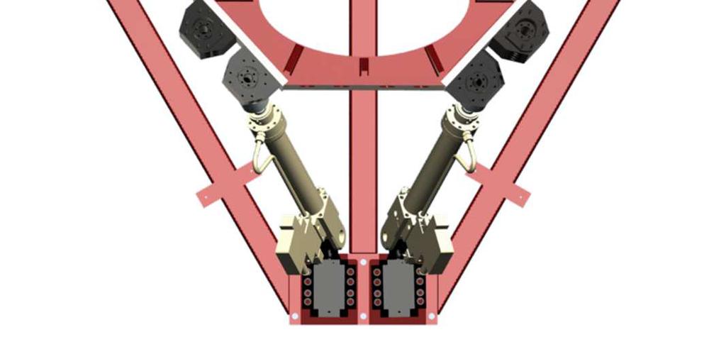
25 LBF BiAx Fatigue Test Machine Failed component UC11 bre Seite 3 Fraunhofer LBF


26 Failed shaft Failed cross section UC11 bre Seite 4 Fraunhofer LBF

27 Failed shaft Texture of fracture surface Complete circumference shows crack initiation Grid lines displays direction of crack growth Fatigue fracture surface Force fracture surface UC11 bre Bearing side Seite 5 Fraunhofer LBF
 Test rig hardware for special applications!")
28 LBF BiAx Test Machines Overview Heavy duty LBF N1: since 1985 LBF N2 LBF N3 LBF N4: since 2001 (LBF N5: since 2013) Test rig hardware for special applications! UC11 bre Seite 6 Fraunhofer LBF

29 Load file comparison: Crane vs. standard Driving w/ load Driving w/ load UC11 bre Biax F v [kn] LBF automobile crane LBF standard FAL Biax F h [kn] Seite 7 Fraunhofer LBF
30 Content Test rig fatigue Crack check methods Wheel end sensitivities UC11 bre Seite 8 Fraunhofer LBF

31 Crack check method Failure detection Type I Censoring Units Runtime failed not failed Dye-penetration method acc. to LBF VB All metallic materials can be checked UC11 bre - There must be a certain crack depth for effective operation Seite 9 Fraunhofer LBF


32 Crack check NDT & DT No crack indication by dye-penetration method Magnetic method indicates fatigue cracks Macrostructure displays visible fatigue cracks UC11 bre Seite 10 Fraunhofer LBF


33 SEM investigation Area of fatigue fracture Area of force fracture UC11 bre Seite 11 Fraunhofer LBF
34 Content Test rig fatigue Crack check methods Wheel end sensitivities UC11 bre Seite 12 Fraunhofer LBF


35 Influence of wheel bolt system on the hub life UC11 bre Seite 13 Fraunhofer LBF
36 Influence of wheel bolt system on the hub life (II) A B C Reference bolt Assembly RFS for design spectrum (normalized) Mileage reachable [km] Normal 100% 500,000 W/o bolt A 110% 250,000 W/o bolt A+B 119% 140,000 W/o bolt A+B+C 128% 85,000 UC11 bre Seite 14 Fraunhofer LBF
37 Customer question»does it mean that in an actual biaxial test of a steel wheel there would different results if I used an actual hub compared with a very stiff adapter?«uc11 bre Seite 15 Fraunhofer LBF


![/RFS drum 1 RFS [MPa] 2 3 Strain](/docs-images/74/70133846/images/38-2.jpg "gauge no.")
38 Implication of brake system on wheel life FAL wheel end F v,stat = 37.5 kn Wheel OS160 Drum brake hub RFS disk /RFS drum 1 RFS [MPa] 2 3 Strain gauge no. UC11 bre Disk brake hub Seite 16 Fraunhofer LBF
39 Summary Main shaft is designed and dimensioned properly for the standard applications. Its recent failure is more related to high-performance requirements. US crack check procedure has to be developped in order to perform preemptive checks at the shaft. Magnetic method already included into standard procedure. It is an excellent method to detect initial fatigue cracks on non-aluminum metallic components. Within the scope of biax fatigue testing, all stiffness relevant attachment parts have to be taken into consideration in order to reproduce the interactions acc. to reality. UC11 bre Seite 17 Fraunhofer LBF
40 LBF TEST STRATEGY FROM THE ROAD TO THE LAB 11 th Users Conference on BiAxial Fatigue Testing November 6 th, 2013 Robert Keplin M.Sc. Fraunhofer-Institut für Betriebsfestigkeit und Systemzuverlässigkeit LBF Fraunhofer LBF
41 Content LBF testing strategy Wheel design spectrum Wheel test spectrum Measurements on BiAxial test machine with full face steel wheel equipped with Strain gauges LBF wheel test load file AKR wheel test load file SAE wheel test load file Conclusion Seite/Page 2 Fraunhofer LBF
42 LBF Test Strategy for structural durability testing Time history from customer usage transferred to appropriate user spectra Load assumptions Determination of local peak stresses Derivation of design spectrum Fatigue life evaluation Adaptation of standardized load files / Development of individual load files Seite/Page 3 Fraunhofer LBF

43 Determination of vehicle type specific loading Definition of Standards / Loading Conditions LBF Road Load Data Library Vehicle load data acquisition Peak loading conditions Race track e.g. Nürburgring Proving ground Other test tracks Seite/Page 4 Fraunhofer LBF

44 Wheel Partial Spectra and Total Design Spectrum Load Case Straight Driving Local Stress Amplitude (lin) Sa 2 Sa 2 Cornering + = Straight Driving Straight Driving Spectrum Cornering Spectrum Design Spectrum Sa 1: Stress Amplitude under F z,stat Sa 2 : Stress Amplitude under F zs,max and F ys,max N s : 96% of Design Life N 1 : 0.5 x 10⁻⁶ x N s N 2 : 50% of N s Load Case Cornering Sa 1 : Stress Amplitude under F z,stat Sa 1 Sa 2 : Stress Amplitude under F zc,max and F yc,max N Design N c : 4% of Design Life N 1 N 1 N 2 N c N 2 N s N 1 : 12.5 x 10⁻⁶ x N c Cycles N (Log) N 2 : 50% of N c Seite/Page 5 Fraunhofer LBF
45 Test Time Reduction by appropriate Acceleration Strategy Derivation of reduced, but damage equivalent test spectrum Cycle modification by omission of small stress cycles Increasing the number of maximum/high stress cycles»ballooning«in the finite life area Seite/Page 6 Fraunhofer LBF
46 Basic Design Spectrum for 300,000 km of Service and Test Spectrum Test duration for passenger car wheels Aluminum wheels: 10,000 km Steel wheels: 8,000 km Seite/Page 7 Fraunhofer LBF


47 Experimental stress analysis LBF flat track Strain gauges Experimental stress analysis with maximum driving loads Copy of the driving surface by nearly flat surface with rolls Under load rotating wheel/tire-system and data transfer via slip ring Seite/Page 8 Fraunhofer LBF
48 Stress based cumulative damage of design spectrum normalized stress amplitude (lin) 1,1 1,0 0,9 0,8 0,7 0,6 0,5 0,4 0,3 0,2 0,1 LBF 0,0 1,0E+01 1,0E+02 1,0E+03 1,0E+04 1,0E+05 1,0E+06 1,0E+07 1,0E+08 1,0E+09 LBF No. XXX; XXX; SGX design spectra: km on road; off road: 0km design spectra: D=0,5; test spectra: D=0 straight driving: 111MPa cornering: 134MPa off road: 0MPa parking: 0MPa required fatigue strength: k= 6; k = 11; Nd= ; Sd=+/- 83,17MPa; R= -1; Pü= 90% no. of cycles (log) Stress based cumulative damage of design spectrum Calculation of RFS values - Required Fatigue Strength Fatigue life evaluation on the basis of RFS values Seite/Page 9 Fraunhofer LBF
 AKR wheel test load file Standardized load file (actuator loads) Matched acc.")
49 Test machine measurements with 3 standardized load files LBF type A BiAxial test machine LBF wheel test load file Matched acc. to LBF approach (rated wheel load, vehicle type, wheel size, tire ratio) AKR wheel test load file Standardized load file (actuator loads) Matched acc. to rated wheel load SAE wheel test load file Standardized load file acc. to SAE J2562 Medium speed and high speed load sequences Matched acc. to rated wheel load Wheel tested with complete original wheel end Seite/Page 10 Fraunhofer LBF
50 Comparison by means of RFS value concept 1 0,89 0,98 1,00 0,94 0,98 RFS value relative to LBF load file [ ] 0,72 0,59 0,59 0,67 0,60 0 inner rim flange spoke center spoke border drop center bead seat LBF load file [8,000 km] AKR load file [8,000 km] SAE load file [8,000 km] Seite/Page 11 Fraunhofer LBF
51 Comparison by means of RFS value concept RFS value relative to LBF load file [ ] 1 0,89 0,90 0,98 0,75 1,00 0,77 0,94 0,85 0,98 0,77 0 inner rim flange spoke center spoke border drop center bead seat LBF load file [8,000 km] AKR load file [8,000 km] SAE load file [64,000 km] Seite/Page 12 Fraunhofer LBF
52 Conclusion Evaluation of structural durability by means of BiAxial wheel testing is still a high complex process To be considered parameters are: Customer usage transferred to design spectra Derivation of a damage equivalent individual / standardized load file and test strategy Definition of minimum requirement of runtime and failure criterions Different possibilities to realize Standardized load file acc. to e.g. LBF, AKR, SAE Individual OEM spec. Comparison of test results of different spec s should be done carefully Seite/Page 13 Fraunhofer LBF


53 Thank you for your attention. we will keep your wheels running Seite/Page 14 Fraunhofer LBF
54 UC th Users Conference on BiAxial Fatigue Testing November 6 th, 2013 Archivierungsangaben Dipl.-Ing. Andreas Friedmann Fraunhofer-Institut für Betriebsfestigkeit und Systemzuverlässigkeit LBF Fraunhofer LBF


55 IDENTIFICATION OF WHEELS' GLOBAL EIGENFREQUENCIES AND MODESHAPES Archivierungsangaben Seite 2 Fraunhofer LBF
56 AGENDA What are the main modeshapes of a wheel? Movitation / Information»inside«the modeshapes Experimental Identification Eigenfrequencies of different wheels Archivierungsangaben Seite 3 Fraunhofer LBF
57 What is a modeshape? Preliminary remark: This all is a matter of structural dynamics / vibrations / Structures»love«to vibrate at distinct frequencies [ This is why we can build and tune musical instruments! ] Those are called Eigenfrequencies or Resonant Frequencies Archivierungsangaben The vibration pattern (or the form of the movement) at a special Eigenfrequency is called a modeshape Modeshape mostly have»simple«and»nice«patterns Seite 4 Fraunhofer LBF


58 What is a modeshape? (cont.) Fraunhofer LBF Seite 5 Archivierungsangaben
 Fraunhofer LBF Seite 6")
59 What is a modeshape? (cont.) Fraunhofer LBF Seite 6 Archivierungsangaben


60 What are the main modeshapes of a wheel? Fraunhofer LBF Seite 7 Archivierungsangaben
61 Movitation / Information»inside«the modeshapes Confirmation of numical models Eigenfrequencies and Modeshapes are quickly calculated in FEM Eigenfrequencies and Modeshapes can be measured»comfortably«the Comparison of Eigenfrequencies is straight forward The Comparison of Modeshapes is possible as well Archivierungsangaben Eigenfrequencies and Modeshapes are connected to different stiffnesses some with relevance to ride and handling issues some with relevance to NVH issues fatigue loading the quality of the manufactoring process Seite 8 Fraunhofer LBF


62 Experimental Identification Fraunhofer LBF Seite 9 Archivierungsangaben

63 Archivierungsangaben Experimental Identification (cont.) Seite 10 Fraunhofer LBF
 Fraunhofer LBF Seite 11")
64 Experimental Identification (cont.) Fraunhofer LBF Seite 11 Archivierungsangaben
65 Experimental Identification (cont.) Table Degrees of freedom Frequencies Safe Modeshapes (sensors) 2 all all (like the shown videos) all 8 12 Archivierungsangaben Seite 12 Fraunhofer LBF
66 Eigenfrequencies of different wheels frequency [Hz] disc roll 1st rim deformation Archivierungsangaben wheel diameter [ ] Seite 13 Fraunhofer LBF
67 Thank you for your attention! Fraunhofer LBF Seite 14 Archivierungsangaben
68 New Concepts for Drivetrain and Wheel Design R&D Division System Reliability Fraunhofer-Institut für Betriebsfestigkeit und Systemzuverlässigkeit LBF Fraunhofer
69 Lab accelerated life testing Enhancing road to lab by using hexapod kinematics In-wheel electric motors and new vehicle concepts Validation of new electric drivetrain concepts by completing functional DOF for lab testing New tire and wheel design for energy efficiency Fraunhofer
 and wheel spoke (1 to 4) Wheel")
 and laboratory testing 6 2 1 5 3 4")
70 Enhancing road to lab Strain gauges applied on wheel well (5, 6) and wheel spoke (1 to 4) Wheel used on C-platform vehicle at both, proving ground (PG) and laboratory testing Fraunhofer
71 PG rough road section Double amplitude [µm/m] Cumulative number of cycles [] Fraunhofer
![Max. stresses at PG driving Cornering Rough road Stress amplitude [Mpa] PG section](/docs-images/74/70133846/images/72-1.jpg "Reference gauge position at aluminum wheel and hub structure Max.")
72 Max. stresses at PG driving Cornering Rough road Stress amplitude [Mpa] PG section Reference gauge position at aluminum wheel and hub structure Max. stress amplitudes Fraunhofer


73 LBF hexapod lab test machine W/ALT: 97 kw Max Nm Till 200 km/h 6-DOF- Kinematic Fv till 30 kn Fh till 20 kn Fraunhofer


74 Camber and steering angle Fraunhofer

75 W/ALT parameter sweep Identification of local stresses at lab testing Service mode: BiAx Vertical and lateral forces, as well as camber angle Service mode: Road simulation Vertical and lateral forces, as well as camber & steering angle Camber angle Vertical load Load [kn] Camber angle [ ] Lateral load Time [s] Fraunhofer

![amplitude [ ] Cornering](/docs-images/74/70133846/images/76-2.jpg "Rough road Fraunhofer")
76 Stress results compared to PG Normalized stress amplitude [ ] Cornering Rough road Fraunhofer
77 Lab accelerated life testing Enhancing road to lab by using hexapod kinematics In-wheel electric motors and new vehicle concepts Validation of new electric drivetrain concepts by completing functional DOF for lab testing New tire and wheel design for energy efficiency Fraunhofer

78 Vehicle dynamics issues Heavy mass of powertrain moves CoG in front of the vehicle Longitudinal dynamics braking becomes an issue with regard to vehicle stability Vehicle layout does not allow mass optimization at the vehicle rear Fraunhofer


79 New vehicle concepts Combining wheel and drivetrain ensures maximum flexibility with regard to vehicle layout and package In-wheel motors Fraunhofer

80 In-wheel motor for new vehicles Fraunhofer

 < 45 kg fig.")
81 Fraunhofer in-wheel motor FhG PSM direct torque motor Peak performance 50 kw Max. torque 700 Nm Weight (incl. inverter) < 45 kg fig.: FhG/IFAM Fraunhofer


82 Effect of unsprung masses Math modeling of full vehicle MBD to predict the effect of unsprung mass Ride & handling and durability events were analyzed Fraunhofer
 to evaluate loads to chassis/body Unsprung mass")

83 RLD tests Road load data (RLD) tests on proving ground (PG) to evaluate loads to chassis/body Unsprung mass almost doubled because of in-wheel motor To quantify impact on chassis loads, vehicle dynamics and NVH behaviour Fraunhofer


84 Vertical forces at PG testing Cumulative damage effects based on unsprung mass by in-wheel motor are in a range of 2.5 compared to baseline Fraunhofer
85 Lab accelerated life testing Enhancing road to lab by using hexapod kinematics In-wheel electric motors and new vehicle concepts Validation of new electric drivetrain concepts by completing functional DOF for lab testing New tire and wheel design for energy efficiency Fraunhofer

86 Schaeffler e-wheel Drive Fraunhofer


87 Measurement equipment Cooling Temperature Flow rate Pressure Torque and cycles Fraunhofer


88 Measurement equipment Structure born noise Integrated optical air gap measurement device Fraunhofer


89 Measurement equipment Data transmission by telemetry system Temperature on rotating and not rotating parts incl. solenoids Fraunhofer

90 Structural stress monitoring Sensors within electromagnetic environment Standard strain gauges w/ copper lack wire sample rate 10 khz Magnetic resistant strain gauge having shielded copper strands sample rate 10 khz Fiber-Bragg Gratings fiber optical sensors w/ glas fiber wire sample rate 1 khz Fraunhofer


91 Enhanced W/ALT Test Equipment Fraunhofer
92 Air gap dependent on y-force Radkräfte [kn] Luftspalt - TP 1 Hz [mm] Air gap 1 Hz signal [ ] Wheel forces [ ] Fx (TP-1Hz) kn Fy (TP-1Hz) kn Zeit [sek] Zeit [sek] Fraunhofer
93 Lab accelerated life testing Enhancing road to lab by using hexapod kinematics In-wheel electric motors and new vehicle concepts Validation of new electric drivetrain concepts by completing functional DOF for lab testing New tire and wheel design for energy efficiency Fraunhofer
94 Loads introduced by curb Elliptical curb [40 x 30 mm] Wheel force [kn] Rolling distance [mm] Fraunhofer


95 New tires New tire dimensions for e.g. reduced rolling resistance Small cars 115/65 R15 BMW i3 155/70 R19 Medium size cars 205/50 R21 LBF FSEM II in-wheel drive 215/30 R20 Foto: BMW New tire/wheel concepts Foto: Bridgestone Foto: Hankook Foto: MAN Fraunhofer


96 CFRP in-wheel motor design CFRP wheel structure 15 7-spoke design Integration and weight reduction Fraunhofer


97 Lab accelerated life testing Enhancing road to lab by using hexapod kinematics In-wheel electric motors and new vehicle concepts Validation of new electric drivetrain concepts by completing functional DOF for lab testing New tire and wheel design for energy efficiency Fraunhofer
98 CRITICALITY RARE EARTH 11 th Users Conference on BiAxial Fatigue Testing November 6 th, 2013 Archivierungsangaben Dipl.-Wirt.-Ing Chaikhani El Hafadh Fraunhofer Institute for Structural Durability and System Reliability LBF Fraunhofer LBF
99 CONTENTS Center for System Reliability with Focus on Electromobility ZSZ-e Our focus Project criticality rare earth Work package; optimized design Archivierungsangaben Seite 2 Fraunhofer LBF

100 CENTER FOR SYSTEM RELIABILITY WITH FOCUS ON ELECTROMOBILITY Archivierungsangaben Seite 3 Fraunhofer LBF


101 CENTER FOR SYSTEM RELIABILITY WITH FOCUS ON ELECTROMOBILITY ZSZ-e AdRIA Archivierungsangaben Budget: > 22 million Rebuilding and renovation New construction Initial installation Area: Office: LBF today: ca m² with ZSZ-e: ca m² Laboratory: LBF today: ca m² with ZSZ-e: ca m² TZA Seite 4 Fraunhofer LBF


102 OUR FOCUS Power-Flow Optimized design of traction motor Power electronics Archivierungsangaben Battery testing system Climatic chamber Multi-axial simulation table (MAST) Modern transmission/motor test bench Bild; HBM Seite 5 Fraunhofer LBF


103 OUR FOCUS EXPERTISES / SELECTED PROJECTS INNOVATIVE MOBILITY SOLUTIONS / RESEARCH FLEET Battery testing system Load data acquisition / load data analysis Development of appropriate testing procedures Derivation of simplified tests and testing guidelines System Analysis (module, total battery, cooling system, BMS) Archivierungsangaben Benziner-Smart E-Smart Nissan Leaf Artega GT Seite 6 Fraunhofer LBF


-Fe-B magnets in the")
104 PROJECT CRITICALITY RARE EARTH NETWORKING material substitution Project duration Partners; Fraunhofer institutes ISC, ISI, IFAM, IGB, IWM, IWU efficient processes Archivierungsangaben optimized design design for recycling Reducing the specific primary needs of heavy rare earths elements Benchmark: Today (Nd, Dy)-Fe-B magnets in the automotive field Seite 7 Fraunhofer LBF
105 PROJECT CRITICALITY RARE EARTH CHALLENGE Nd-Fe-B for high efficiency/power density Many motors for mobile application use RE PM Up to several kg of Nd-Fe-B magnet Serious increase in price of RE Price development dependence How to reduce RE magnet and therefore to achieve the independence of RE Archivierungsangaben Technologiemetalle.org, Stand: Seite 8 Fraunhofer LBF


106 PROJECT CRITICALITY RARE EARTH WORK PACKAGE OPTIMIZED DESIGN/TECHNICAL CHALLENGE Source of losses in PMSM Stator-Losses Current heat losses (Stator winding) Core losses Rotor-Losses Core losses Bearing friction losses Archivierungsangaben Air friction in the air gap Not optimized cooling system Nollau/Gerling 2013 Seite 9 Fraunhofer LBF


107 PROJECT CRITICALITY RARE EARTH WORK PACKAGE OPTIMIZED DESIGN/TARGET 20-30% reduction of primary RE by efficient cooling and improved design conventional traction motor wheel hub motor Archivierungsangaben Source: Bosch rare permanent magnet Source: IFAM Seite 10 Fraunhofer LBF
108 PROJECT CRITICALITY RARE EARTH WORK PACKAGE OPTIMIZED DESIGN/COUNTERMEASURE Rotor optimization Magnet geometry Magnet placement; surface / buried Archivierungsangaben Surface Mounted Inset Mounted Interior circumferential radial Stator Improvement Conductor cross-section Number of windings Stator metal sheet cutting Optimize the cooling system Source: Bernatt 2007 Seite 11 Fraunhofer LBF
109 Thank you for your attention Archivierungsangaben Seite 12 Fraunhofer LBF
110 11th International Users Conference on Biaxial Wheel Fatigue Testing November 6, 2013 Industry-Leading Commercial Vehicle Products Implementation of Biaxial Testing at Accuride Paul Simms BSME MBA Manager of Mechanical Labs accuridecorp.com


111 Topics to Cover History of Accuride Accuride Today Why invest in Biaxial testing Trials of Implementation Successes of Implementation Summary Questions Front View of Test Rig Test Rig Enclosure accuridecorp.com 2


112 Company History Gunite forms in Rockford, Illinois Henderson Steel Wheel Plant Opens Bain Capital Firestone Buyout, Accuride is Formed Stock relisted NYSE with ticker ACW Future Henderson Firestone Forms Steel Products Imperial Fabricating Forms Sold to Phelps Dodge Acquisition of TTI business Pursuit of Growth Brillion Iron Works ductile iron foundry 1998 Sold to KKR Divest Bostrom, Fabco & Brillion Farm More than 150 Years of Industry-Leading Performance accuridecorp.com 3


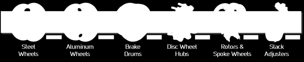
113 Accuride Today Leading supplier of components to North American commercial vehicle industry #1 producer of steel wheels; #2 producer of aluminum wheels Brake drums, disc wheel hubs and slack adjusters among leaders in their categories 3 Business units Wheels, Gunite & Brillion with 9 operational sites 2,250 associates in North America Serve Class 5-8 Industry OEM (Truck & Trailer) and Aftermarket segments $929.8 million FY 2012 Consolidated Revenue, as follows: Business Customer Market Brillion 17% Imperial 14% Wheels 45% Other 48% Paccar 19% Navistar 13% Military 3% Trailer 7% Other 17% Class % Gunite 24% Volvo/ Mack 8% Daimler 12% A/M 29% accuridecorp.com 4
114 Why Invest in Biaxial Testing Why Invest in Biaxial Testing accuridecorp.com 5


115 Accuride s Strategic Vision Accuride Vision: Accuride will be the premier supplier of wheel-end system solutions to the global commercial vehicle industry #1-2 globally in wheel-end systems ROIC > 20% through a cycle >80% of revenue from CORE products Balanced geographical revenues: 40% North America 30% Asia 20% Europe 10% South America Our Focus >25% of annual revenues from new and evolutionary products >95% retention of personnel Maximize ACW share price accuridecorp.com 6
116 Reasons for Accuride to Invest Customers asking Accuride to provide wheels outside of North America Global test requirements mandate Biaxial testing Europe ES3.23 Brazil ABNT NBR 6751 Volvo Timing and cost to test at LBF Fraunhofer in Germany Three to six months to qualify wheel at LBF Cost is recaptured with 20 qualified designs accuridecorp.com. 7
117 Reasons for Accuride to Invest Accuride s global competitors have biaxial test rigs Alcoa Hungary Gianetti Italy Maxion Brazil, Germany and Turkey Wheels India India SAE committee formed to develop biaxial testing North America Class 5 8 Trucks Testing of wheels and wheel ends as assemblies Accuride does not want to left behind The moment you stop improving your organization, it starts to die. Mike Litman accuridecorp.com 8


118 Biaxial Timeline Test rig shipped from Germany to US via boat Reassemble test rig at Accuride Accuride visits Germany for training & testing Dec 2012 Dec 2013 PO issued for Type N Test Rig Test rig being built in Germany Sept. Runoff in Germany Machine certified by LBF Controls Issue LBF at Accuride For Training C H load cell issues LBF at Accuride to repair load cell Test rig running reliably accuridecorp.com 9

119 Challenges of Implementing Delays in getting UL approved equipment for US Power difference of 50 hz v. 60 hz Brand new set of controls never used before More control of the system Control position tolerances on every load step More feedback monitoring Cooling fan Controls Interface accuridecorp.com. 10
120 Challenges of Implementing Language & cultural differences Three different managers of project at Accuride Commissioning was during holiday season of November and December. Lack of familiarity with bi-axial test method Competitor wheel testing on Accuride s test rig Assumption made wheels are tested to EUWA ES 3.23 Competitor wheels are cracking before minimum cycles Tire life typically 10,000 km Mounting hardware life new mounting every test accuridecorp.com 11
121 Successes of Implementation Great support from LBF Fraunhofer Phone Remote computer control Commissioning improved when LBF had a duplicate test rig Verified performance of Accuride wheels qualified at LBF Fraunhofer Have a test rig that runs consistently Has reduced Accuride s development cost and time for new wheel development accuridecorp.com 12

 160 150 140 130 120 110 100 Pressure Chart Position 1 www.advantagepressurepro.")
122 Tire Pressure Monitoring Using Pressure Pro tire pressure monitoring system to monitor tire pressure. Records tire pressure in 15 minute intervals and is adjustable. Records pressure in PSI, Bar or kpa from.7 Bar to 13.7 Bar. Data downloads into EXCEL via serial port. Pressure (PSI) Pressure Chart Position 1 Reading Date accuridecorp.com. 13


123 Developed Calibration Wheel Developed with help of LBF Fraunhofer Wireless Telemetry Using Lord MicroStrain V- Link -LXRS Wireless Seven Channel Analog Input Sensor Node boxes Boxes wirelessly transmit live synchronized data to computer Can store 4 MB of data V-Link Box and custom enclosure Flange V-Link Wheel accuridecorp.com. 14


124 Calibration Fixture Developed fixture to measure vertical and horizontal force Remove Damper and replace with rigid link Drum Calibration Fixture Rigid Link Test Rig Shaft Load cell on calibration fixture Gamma Setting & Rigid Link Set Gama to 330 mm to level horizontal cylinder accuridecorp.com. 15
125 Summary Reasons to invest in Biaxial Testing Accuride s Vision to be the premier supplier of wheel end system solutions to the GLOBAL commercial vehicle industry. Global test requirements mandate Biaxial testing Timing and Cost to test at LBF Fraunhofer in Germany Accuride s national and international competitor have test rigs May become North America standard test Timeline 2010 Accuride orders LBF Fraunhofer Type N Biaxial test rig 2011 Test rig installed at Accuride 2012 Accuride starts testing on Biaxial test rig accuridecorp.com. 16
126 Summary Challenges System controller issues Understanding the end of test criteria Designing wheels to pass the stringent biaxial load file Successes LBF Fraunhofer has been great support through the implementation process Test machine has run all of 2013 without issues Accuride invested in Biaxial testing to compete in the global heavy truck market accuridecorp.com 17

127 Questions Questions accuridecorp.com 18


128 Industry-Leading Commercial Vehicle Products


129 Pre-damage as integrative part of durability sign-off of aluminium wheels Dr. Wolfram Weiss Dr. W. Weiss, Pre-damage as integrative part of durability sign-off of aluminium wheels Nov 2013
130 1. Why pre-damage? Introduction and theoretical background 2. Test facilitiy 3. Impact definition 4. Evaluation of impact parameters 5. Predamage Process 6. Special studies 7. Summary & Conclusion 2 Dr. W. Weiss, Pre-damage as integrative part of durability sign-off of aluminium wheels Nov 2013
131 1. Why pre-damage? Automotive wheels are safety critical components, as such durability standards have to accomplish customer demand appropriately. The demand for big wheels (low tire side wall height), has grown significantly over the recent years and driving through potholes is a normal driving behaviour. 3 Dr. W. Weiss, Pre-damage as integrative part of durability sign-off of aluminium wheels Nov 2013
 Typical failure modes on Light alloy")


132 1. Why pre-damage? (failure modes) Typical failure modes on Light alloy wheels Spoke area Inner flange Spoke/Disc cracks are mainly caused by cornering events and therefore covered by Bi-axial wheel Testing Inner flange cracks are mainly caused by combination of a PRE-DAMAGE (obstacle or pothole) with rim rolling event 4 Dr. W. Weiss, Pre-damage as integrative part of durability sign-off of aluminium wheels Nov 2013
133 1. Why pre-damage? Bi-axial wheel testing is the most economical laboratory test to validate the endurance of a wheel but it can t simulate extreme radial forces (e.g. caused by road obstacles or potholes). Based on above specifically for Aluminium wheels any Bi-axial wheel test has to be executed with a PRE-DAMAGED wheel in order to validate the influence of dynamic impacts happening on the road. 5 Dr. W. Weiss, Pre-damage as integrative part of durability sign-off of aluminium wheels Nov 2013
 Undamaged wheel shows no visible cracks after 3 life cycles")

134 1. Why pre-damage? (example) Undamaged wheel shows no visible cracks after 3 life cycles on BiAx rig. point of impact Pre-damaged wheel with 2mm dent fails after 1 life cycle on BiAx rig. 6 Dr. W. Weiss, Pre-damage as integrative part of durability sign-off of aluminium wheels Nov 2013
 Wheel Dynamic Loads and their effect on the microstructure Example of driving through a sequence of Potholes force Flow stress can increase or decrease with strain rate.")
135 1. Why pre-damage? (strain rate) Wheel Dynamic Loads and their effect on the microstructure Example of driving through a sequence of Potholes force Flow stress can increase or decrease with strain rate. In principle, for most aluminum alloys the resistance to flow increases with increasing strain rate (positive strain rate sensitivity). Contrary to that the adiabatic process of high strain rate leads to thermal activation. Investigations in AlSiMg-alloys showed negative strain rate sensitivity with high strain rates. It is assumed that the adiabatic heating is the reason for this behavior*) time Definition of dynamic load: dε dt 10 1 s 1 *) Ostermann, Friedrich: Anwendungstechnologie Aluminium.. 7 Dr. W. Weiss, Pre-damage as integrative part of durability sign-off of aluminium wheels Nov 2013


136 2. Test Facilities Dynamic impacts (pothole, curb) may lead to small local deformation causes inner local stress Biaxial Fatigue Test Load spectrum includes: Radial loads Lateral loads Radial impact test rig of TÜV NORD in Essen (source: TÜV Nord Group) FORD-facility 8 Dr. W. Weiss, Pre-damage as integrative part of durability sign-off of aluminium wheels Nov 2013
 depends on Pothole depth, length and shape Tire pressure ptire Tire size Vehicle speed vvehicle Payload Axle load Faxle Suspension geometry and")
137 3. Impact definition Passing square edge chuckhole is identified as most severe event with customer usage Event is dynamic in the sense that / 0.1/s (important for aluminium wheels). Driving direction 9 Resultant radial wheel force F(t) depends on Pothole depth, length and shape Tire pressure ptire Tire size Vehicle speed vvehicle Payload Axle load Faxle Suspension geometry and stiffness Translate to rig parameters vehicle type Dr. W. Weiss, Pre-damage as integrative part of durability sign-off of aluminium wheels Nov 2013
 Chuckhole Road Spring Shock Unsprung Mass Tire Bump Stop Why go through MBS?")
138 4. Evaluation of impact parameters How to use a lab test to generate similar tire/wheel damages from the full vehicle PG test?? Simulation Scheme Sprung Mass Multi Body Simulation (MBS) Chuckhole Road Spring Shock Unsprung Mass Tire Bump Stop Why go through MBS? It is easier (1) to retrieve the information to define the impact test and (2) to include latest design changes. 10 Dr. W. Weiss, Pre-damage as integrative part of durability sign-off of aluminium wheels Nov 2013

139 4. Evaluation of impact parameters (energy) CAE simulation Model Full vehicle suspension Linear spring Non-linear damping Non-linear jounce bump stop 2-D Road definition Tire model RLD DB correlate model Simulation Scheme Chuckhole Road Spring Sprung Mass Shock Unsprung Mass Tire Bump Stop Input is bi-linear force deflection curve for tire model Chuckhole RLD to prove the model Output is: force F(t) and deflection x(t) as function of time, and maxima F max and x max Required energy: 1 force E deflection 11 Dr. W. Weiss, Pre-damage as integrative part of durability sign-off of aluminium wheels Nov 2013
 the local force of phase 2 is released tire expands again Obviously only in phase C2 a possible dent can be induced 12 Dr. W.")
140 4. Evaluation of impact parameters (velocity) Phases of the Chuckhole Event Case I A B C Case II A B C force C2 C3 C1 C4 time tire is deformed and air is compressed local contact between chuckhole edge and wheel rim (via the tire rubber) the local force of phase 2 is released tire expands again Obviously only in phase C2 a possible dent can be induced 12 Dr. W. Weiss, Pre-damage as integrative part of durability sign-off of aluminium wheels Nov 2013
141 4. Evaluation of impact parameters What is the right energy for pre-damaging impact? Integration of force/deflection curve (limit from MBS) What is the mass/velocity combination to provide this energy? Choose appropriate striker mass to meet PG time scale This is sufficient to fulfill dynamic load condition: dε dt s Dr. W. Weiss, Pre-damage as integrative part of durability sign-off of aluminium wheels Nov 2013
 CAE 2D ADAMS chuckhole simulation RLD DB")
 point of impact deflection E deflection")

142 5. Predamage Process I) Measure Tire deflection II) CAE 2D ADAMS chuckhole simulation RLD DB III) Perform Impact E req force force E req = E (1+a s ) point of impact deflection E deflection 14 Dr. W. Weiss, Pre-damage as integrative part of durability sign-off of aluminium wheels Nov 2013


143 6. Special studies Impact Location mm mm Measure distance before and after impact mm mm mm mm mm mm mm 7 spokes: Valve position is weakest location 5 spokes: Valve position is a little bit weaker 8x2 spokes: Valve position is not weakest mm mm mm mm Use valve position for impact location Dr. W. Weiss, Pre-damage as integrative part of durability sign-off of aluminium wheels Nov 2013


144 6. Special studies Multiple vs Single Strike Results Impacts with increased energy Single strike: dent = 2.1 mm Multiple strikes: dents = 1.9, 2.0, 2.1 mm Single strike = 2.6 M Life time does not depend on number of strikes One single strike is sufficient for wheel predamage Multiple strikes = 2.9 M all three locations Dr. W. Weiss, Pre-damage as integrative part of durability sign-off of aluminium wheels Nov 2013
145 7. Summary & Conclusion 3 Map of impacts 2,5 Dent depth [mm] 2 1,5 1 Impact Energy according to Multi Body Simulation increased energy to provoke fatigue failure 0,5 no failure test stopped FORD target 0 1,0E+06 1 Life; 5,0E+06 # of cycles 1,0E Dr. W. Weiss, Pre-damage as integrative part of durability sign-off of aluminium wheels Nov 2013
146 7. Summary & Conclusion Pre-damage is a substantial part of fatigue life of Al-wheels in real world usage. Pre-damage is formed by dynamic events (e.g. road obstacles or potholes). Impact is defined by Proving Ground event MBS simulation delivers energy and time for the event simulation Use valve position as impact location One single strike is sufficient for wheel predamage 18 Dr. W. Weiss, Pre-damage as integrative part of durability sign-off of aluminium wheels Nov 2013
147 Thank you for your attention 19 Dr. W. Weiss, Pre-damage as integrative part of durability sign-off of aluminium wheels Nov 2013

148 Raising Efficiency in Latest Wheel/Hub Simulation by Using PERMAS Solver Reinhard Helfrich INTES GmbH, Stuttgart Copyright INTES GmbH, Germany, 2013 Raising Efficiency in Latest Wheel/Hub Simulation by Using PERMAS Solver Page 1

149 Copyright INTES GmbH, Germany, 2013 Raising Efficiency in Latest Wheel/Hub Simulation by Using PERMAS Solver Page 2
150 Contents Topic Application 1. ESPRIT project CAROW Recommendations from Detailed bolt simulation Contact update 3. Simplified bolt model Bolt pretension 4. Piston shaping Shape optimization and contact 5. Rib design Topology optimization for higher stiffness 6. Universal joint Contact tolerance analysis Copyright INTES GmbH, Germany, 2013 Raising Efficiency in Latest Wheel/Hub Simulation by Using PERMAS Solver Page 3
151 Contents Topic Application 1. ESPRIT project CAROW Recommendations from Detailed bolt simulation Contact update 3. Simplified bolt model Bolt pretension 4. Piston shaping Shape optimization and contact 5. Rib design Topology optimization for higher stiffness 6. Universal joint Contact tolerance analysis Copyright INTES GmbH, Germany, 2013 Raising Efficiency in Latest Wheel/Hub Simulation by Using PERMAS Solver Page 4


152 ESPRIT Project CAROW 1998 Copyright INTES GmbH, Germany, 2013 Raising Efficiency in Latest Wheel/Hub Simulation by Using PERMAS Solver Page 5


153 ESPRIT Project CAROW 1998 Copyright INTES GmbH, Germany, 2013 Raising Efficiency in Latest Wheel/Hub Simulation by Using PERMAS Solver Page 6


154 ESPRIT Project CAROW 1998 Copyright INTES GmbH, Germany, 2013 Raising Efficiency in Latest Wheel/Hub Simulation by Using PERMAS Solver Page 7


155 ESPRIT Project CAROW 1998 Copyright INTES GmbH, Germany, 2013 Raising Efficiency in Latest Wheel/Hub Simulation by Using PERMAS Solver Page 8
156 ESPRIT Project CAROW 1998 Copyright INTES GmbH, Germany, 2013 Raising Efficiency in Latest Wheel/Hub Simulation by Using PERMAS Solver Page 9
157 Contents Topic Application 1. ESPRIT project CAROW Recommendations from Detailed bolt simulation Contact update 3. Simplified bolt model Bolt pretension 4. Piston shaping Shape optimization and contact 5. Rib design Topology optimization for higher stiffness 6. Universal joint Contact tolerance analysis Copyright INTES GmbH, Germany, 2013 Raising Efficiency in Latest Wheel/Hub Simulation by Using PERMAS Solver Page 10
158 Bolt assembly Bolt Flat washer 2 Plates Spring washer Nut Copyright INTES GmbH, Germany, 2013 Raising Efficiency in Latest Wheel/Hub Simulation by Using PERMAS Solver Page 11


159 Coupling conditions by contact µ = 0 µ = 0 µ = 0 µ = 0 µ = 0,1 µ = 0,1 Friction for all contacts of the snap ring all contacts of the nut DIN ISO 4014 M20 Standard metric thread HEXE8 Model 12,5 Thread turns µ = 0,1 Note: It is a PERMAS feature to enable contact analysis without friction DIN ISO 4034 M20 Standard metric thread HEXE8 Model 6 Thread turns + runout Copyright INTES GmbH, Germany, 2013 Raising Efficiency in Latest Wheel/Hub Simulation by Using PERMAS Solver Page 12


160 The effect of contact update Copyright INTES GmbH, Germany, 2013 Raising Efficiency in Latest Wheel/Hub Simulation by Using PERMAS Solver Page 13

161 Contact pressure in the thread Copyright INTES GmbH, Germany, 2013 Raising Efficiency in Latest Wheel/Hub Simulation by Using PERMAS Solver Page 14
162 Torque Pretension force vs. VDI screw guidelines Pretension Force vs. Torque Pretension Force [kn] Difference at a: Difference at b: Model 14 and 16 Torque [Nm] Copyright INTES GmbH, Germany, 2013 Raising Efficiency in Latest Wheel/Hub Simulation by Using PERMAS Solver Page 15
163 Contents Topic Application 1. ESPRIT project CAROW Recommendations from Detailed bolt simulation Contact update 3. Simplified bolt model Bolt pretension 4. Piston shaping Shape optimization and contact 5. Rib design Topology optimization for higher stiffness 6. Universal joint Contact tolerance analysis Copyright INTES GmbH, Germany, 2013 Raising Efficiency in Latest Wheel/Hub Simulation by Using PERMAS Solver Page 16

164 Variants of screw models Copyright INTES GmbH, Germany, 2013 Raising Efficiency in Latest Wheel/Hub Simulation by Using PERMAS Solver Page 17

165 Thread coupling Definition of thread area by nodes or element surfaces Pretension in thread area Pretension by force Locking of pretension force after pretension Elongation of bolt as in reality Copyright INTES GmbH, Germany, 2013 Raising Efficiency in Latest Wheel/Hub Simulation by Using PERMAS Solver Page 18

166 with additional flank angle The flank angle will cause a spreading of the bolt hole by pretension force Copyright INTES GmbH, Germany, 2013 Raising Efficiency in Latest Wheel/Hub Simulation by Using PERMAS Solver Page 19

167 with additional pitch The pitch causes a twist of the bolt shaft Copyright INTES GmbH, Germany, 2013 Raising Efficiency in Latest Wheel/Hub Simulation by Using PERMAS Solver Page 20


168 Comparison: v.mises Stress CAU Model Comparison with Pretension Copyright INTES GmbH, Germany, 2013 Raising Efficiency in Latest Wheel/Hub Simulation by Using PERMAS Solver Page 21
169 Contents Topic Application 1. ESPRIT project CAROW Recommendations from Detailed bolt simulation Contact update 3. Simplified bolt model Bolt pretension 4. Piston shaping Shape optimization and contact 5. Rib design Topology optimization for higher stiffness 6. Universal joint Contact tolerance analysis Copyright INTES GmbH, Germany, 2013 Raising Efficiency in Latest Wheel/Hub Simulation by Using PERMAS Solver Page 22

170 Contact Piston - Bolt Copyright INTES GmbH, Germany, 2013 Raising Efficiency in Latest Wheel/Hub Simulation by Using PERMAS Solver Page 23

171 Piston Shape Modification Copyright INTES GmbH, Germany, 2013 Raising Efficiency in Latest Wheel/Hub Simulation by Using PERMAS Solver Page 24

172 Contact Piston Bolt, Results Analysis number Copyright INTES GmbH, Germany, 2013 Raising Efficiency in Latest Wheel/Hub Simulation by Using PERMAS Solver Page 25


173 Final Design of the Piston Optimized bore shape Initial bore shape Copyright INTES GmbH, Germany, 2013 Raising Efficiency in Latest Wheel/Hub Simulation by Using PERMAS Solver Page 26
174 Contents Topic Application 1. ESPRIT project CAROW Recommendations from Detailed bolt simulation Contact update 3. Simplified bolt model Bolt pretension 4. Piston shaping Shape optimization and contact 5. Rib design Topology optimization for higher stiffness 6. Universal joint Contact tolerance analysis Copyright INTES GmbH, Germany, 2013 Raising Efficiency in Latest Wheel/Hub Simulation by Using PERMAS Solver Page 27

175 Engine Model The support of the engine is made at the lower end of the engine block by a so-called minimal support which does not introduce any constraints. Copyright INTES GmbH, Germany, 2013 Raising Efficiency in Latest Wheel/Hub Simulation by Using PERMAS Solver Page 28
 elements.")
.")

 Copyright INTES")

176 Meshing of Design Space Automatic meshing with cube (and wedge) elements. Size of elements depends on the desired size of achieved structures (like ribs). Coupling with wall of crankcase is achieved by projection and interpolation (surface coupling using incompatible meshes) Copyright INTES GmbH, Germany, 2013 Raising Efficiency in Latest Wheel/Hub Simulation by Using PERMAS Solver Page 29

177 Pretension and Temperature with Local Deformation Original model The bending line of the crankshaft axis is taken as reference. The design criterion is built from the sum of displacements on this axis at the main bearings. This criterion shall be minimized by a new rib design. Copyright INTES GmbH, Germany, 2013 Raising Efficiency in Latest Wheel/Hub Simulation by Using PERMAS Solver Page 30

178 Pretension and Temperature with Local Deformation Exhaust side Intake side Copyright INTES GmbH, Germany, 2013 Raising Efficiency in Latest Wheel/Hub Simulation by Using PERMAS Solver Page 31


179 Rib Generation Copyright INTES GmbH, Germany, 2013 Raising Efficiency in Latest Wheel/Hub Simulation by Using PERMAS Solver Page 32


180 Comparison of Deformation Original design Local deformation Copyright INTES GmbH, Germany, 2013 Raising Efficiency in Latest Wheel/Hub Simulation by Using PERMAS Solver Page 33
181 Contents Topic Application 1. ESPRIT project CAROW Recommendations from Detailed bolt simulation Contact update 3. Simplified bolt model Bolt pretension 4. Piston shaping Shape optimization and contact 5. Rib design Topology optimization for higher stiffness 6. Universal joint Contact tolerance analysis Copyright INTES GmbH, Germany, 2013 Raising Efficiency in Latest Wheel/Hub Simulation by Using PERMAS Solver Page 34

182 Tolerance analysis in PERMAS Tolerance analysis by reliability analysis Relevant basic variables contact gap widths, coordinates, geometric element properties Solution methods like DAS, RSM, MCS Results probability of failure due to stress level failure rate and importance values elasticities (sensitivities with respiect to mean value and standard deviation Copyright INTES GmbH, Germany, 2013 Raising Efficiency in Latest Wheel/Hub Simulation by Using PERMAS Solver Page 35


183 Spline shaft connection in 2D Basic variables Copyright INTES GmbH, Germany, 2013 Raising Efficiency in Latest Wheel/Hub Simulation by Using PERMAS Solver Page 36
184 Stochastic model parameters Copyright INTES GmbH, Germany, 2013 Raising Efficiency in Latest Wheel/Hub Simulation by Using PERMAS Solver Page 37

185 Contact analysis Copyright INTES GmbH, Germany, 2013 Raising Efficiency in Latest Wheel/Hub Simulation by Using PERMAS Solver Page 38
186 Analysis with tolerances Copyright INTES GmbH, Germany, 2013 Raising Efficiency in Latest Wheel/Hub Simulation by Using PERMAS Solver Page 39

187 Stresses in the failure state Copyright INTES GmbH, Germany, 2013 Raising Efficiency in Latest Wheel/Hub Simulation by Using PERMAS Solver Page 40
188 Gap width in the failure state Note: Failure state does not occur at extreme values of basic variables but within tolerance interval Copyright INTES GmbH, Germany, 2013 Raising Efficiency in Latest Wheel/Hub Simulation by Using PERMAS Solver Page 41
189 Elasticities Copyright INTES GmbH, Germany, 2013 Raising Efficiency in Latest Wheel/Hub Simulation by Using PERMAS Solver Page 42

190 Thank you very much for your attention! Copyright INTES GmbH, Germany, 2013 Raising Efficiency in Latest Wheel/Hub Simulation by Using PERMAS Solver Page 43
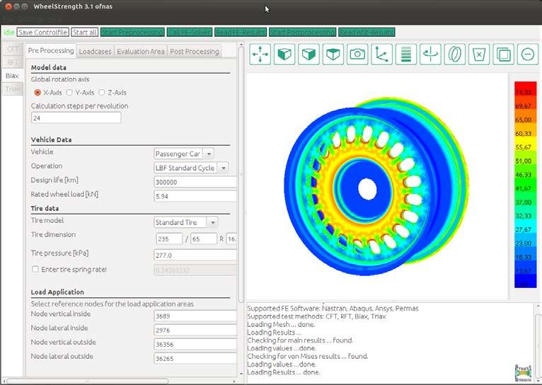
191 WheelStrength 3.0
192 WheelStrength 3.0 The software LBF.WheelStrength/LBF.HubStrength is the main Stress & Strength GmbH product. This innovative software was developed based on the methodology of the biaxial wheel/hub test facility ZWARP and the software gives the possibility to calculate wheels under realistic boundary conditions in the earliest stage of development.

193 WheelStrength 3.0 Method-based Technically mature Interfaces to common FE Solvers User-friendly New Testing Methods
194 WheelStrength 3.0 Former Versions New Version ANSYS WSt WheelStrength 3.0 Patran/Nastran WSt ANSYS Permas Nastran


195 WheelStrength 3.0 New testing methods available Cornering fatigue test Biaxial test rig Rolling fatigue test


196 WheelStrength 3.0 New licencing model WSt client WSt client Floating licence WSt node lock licence WSt licence server WSt node lock licence WSt client WSt client

197 WheelStrength 3.0 own graphics engine
198 WheelStrength 3.0 Create plots Stress history plot Spectra plot

199 WheelStrength 3.0 LBF load spectrum for a fatigue-life calculation Experimental stress analysis/ damage calculation Numerical fatigue analysis LBF WheelStrength LBF ZWARP Design spectra Fatigue testing LBF ZWARP (biaxial testing rig) Damage equivalent, statistically verified and time shortened


200 WheelStrength 3.0 Use suggested load and spectra values as defined by the LBF standard load-cycle or create custom load cases.
201 WheelStrength 3.0 Why numerical pre-design with respect to structural durability?

202 WheelStrength 3.0»Physical tire model«tire-load function

203 WheelStrength 3.0 Development and evaluation

204 WheelStrength 3.0 Development and evaluation

205 Fraunhofer LBF Prof. Dr.-Ing. Andreas Büter Bildquelle: Fraunhofer LBF Damage Tolerance and Fatigue Evaluation of Primary Parts in Composite Challenges of Approval Plastic Wheels
 without any failure.")
 Residual strength The wheel must be able to endure the maximum operational load at any time (also at")
206 Criteria for the Design of Composite Components In principal: Fracture The wheel needs to endure all occurring load cycles during its expected life time (approx km) without any failure. Stiffness degradation The wheel must not exceed maximum allowable deformation! (Usability) Residual strength The wheel must be able to endure the maximum operational load at any time (also at the end of its design life time) ( Avoidance of Sudden Death ) Fraunhofer LBF
207 Rotating Bending Tests on Plastic Wheels rotating mass m measurement of displacement d = d N d O d = 0.1 mm 110 c.g Deflection d in [mm] 0,7 0,6 0,5 0,4 0,3 0,2 0,1 Measurement of displacement in 2 directions M b = 2.2 knm Test criterion: Stiffness loss 10% ( d = 0.1 mm) 1 1,5 2 2,5 3 No. of cycles in 10^5 How to use, this behavior, for an approval plastic wheel? Seite 3 Fraunhofer LBF
208 Existing Rules for Composite Structures in Safety Components FAA 14 CFR / Damage Tolerance and Fatigue Evaluation of Composite Rotorcraft Structures. EASA NPRM: Doc. No. FAA ; Notice No ; 75 FR 793, Jan 6, 2010 Final rule: Doc. No. FAA , 76 FR 74663, Dec. 1, 2011 CS / Damage tolerance and fatigue evaluation of composite rotorcraft structures. NOTICE OF PROPOSED AMENDMENT (NPA) NO UC FAA: Federal Aviation Administration CFR: Code of Federal Regulations; Vol. 14: Aeronautics and Space NPRM: Notice of Proposed Rule Making EASA: European Aviation Safety Agency CS: Certification Specification FR: Federal Register Seite 4 Fraunhofer LBF
209 27.573/ Definitions UC Principal Structural Element (PSE) [ ] structural elements that contribute significantly to the carrying of the loads, the failure of which could result in catastrophic failure of the vehicle. Safety Component like a Wheel! Catastrophic failure [ ] an event that could prevent continued a safe drive! Threat Assessment [ ] assessment that specifies the locations, types, and sizes of damage, considering fatigue, environmental effects, intrinsic and discrete flaws, and impact or other accidental damage (including the discrete source of the accidental damage) that may occur during manufacture or operation. (emphasis added) Seite 5 Fraunhofer LBF
210 Catastrophic Failures for a Car-Wheel are: - Damage without any response to the driver (Sudden Death) - No compliance of damage chain from outer parts to inner parts - Airloss (abrupted / insidious) during the ride - Reduction of the screw prestressing or setting - Loosen of screws and/or other parts of the wheel - Relevant damages are not visible before failure - Fractures with non-visible damages - Stiffness loss higher than 20% over life. -. UC Seite 6 Fraunhofer LBF
211 27.573/ Definitions UC Principal Structural Element (PSE) [ ] structural elements that contribute significantly to the carrying of the loads, the failure of which could result in catastrophic failure of the vehicle. Safety component like a Wheel! Catastrophic failure [ ] an event that could prevent continued safe drive Threat Assessment [ ] assessment that specifies the locations, types, and sizes of damage, considering fatigue, environmental effects, intrinsic and discrete flaws, and impact or other accidental damage (including the discrete source of the accidental damage) that may occur during manufacture or operation. (emphasis added) Seite 7 Fraunhofer LBF


212 Threat Assessment - Types and Sizes of Damage Manufacturing Air Cavities Less resin / Cavities Matrix failure Wrong Fibre volume Wrong Fibre orientation Foreigner Objects Can cause a lost of strength Visible and Non-Visual Damages Operational Use Fibre-matrix failure Matrix failure Delamination Fibre failure Fraunhofer LBF
213 27.573/ Divided Two Possibilities for Proof 1. evaluate [ ] under damage tolerance standards 2. fatigue evaluation If an applicant establishes that [damage tolerance evaluation] is impractical within the limits of geometry, inspectability and good design practice UC In Aerospace: The methodology used to establish compliance with this section must be submitted to and approved by the Administrator. Seite 9 Fraunhofer LBF
214 Damage Tolerance Evaluation Principle Steps Objective: Aviod of a catastrophic failure caused by loading, manufacturing failures and or random damages during use. focused on allowable "life time! Steps: Identification of PSEs Load Analysis to identify the mission loads and all critical load cases Threat Assessment Fatigue and Residual Strength Estimation to identify the time of use Considering a safety factor this Time becomes the inspection or exchange time? UC All influences of scattering in material, manufacturing-process and environment on strength have to be taken into account. Seite 10 Fraunhofer LBF


215 Example - Threat Assessment Important Questions: Which types of failure are possible? Where their usually located? Is a damage visible or other NDT Methods needed? influenced the size of the proofed damage (better NDT smaller damages have to take into account) For the damage tolerance proof all identified types of damages have to take into account! Debonding at hybrid Parts Air Cavities UC Seite 11 Fraunhofer LBF
216 Damage Tolerance Evaluation Exchange Time Objective: Aviod of a catastrophic failure caused by loading, manufacturing failures and or random damages during use. focused on allowable "life time! Determination of the Exchange Times for PSEs: Due to tests or numerical investigations and tests the life time have to be determined, where the PSE is safe (residual strength > loading) under consideration of: all determined damages: damages caused by manufacturing and use (if required also after maintenance) based on the threat assessment UC For the evaluation of these damages the influence on all component and/or vehicle requirements like: stiffness, dynamic behavior and/or strength, have take into account. Seite 12 Fraunhofer LBF
217 Effects of Defects Pressure Strength and Damage Size after Impact Pressure Strength, Damage Size Maximal Allowable Pressure Strength Smallest Detectable Damages NDT Method here: visibility by eye not visible Schematic Damage Size Pressure Strength The chosen NDT-Method define the maximal allowable strength Impact Energy Seite 13 Fraunhofer LBF
218 How to define a maximal allowable damage size? Pressure Strength and Damage Size after Impact Pressure Strength, Damage Size Maximal needed Pressure Strength maximal allowable Damages NDT Method here: visibility by eye not visible Schematic Damage Size Pressure Strength The requirements in strength define the maximal allowable damage size, which have to detected by NDT-Method Impact Energy Seite 14 Fraunhofer LBF Effects of Defects
219 Summary Damage Tolerance Evaluation Objective: Aviod of a catastrophic failure caused by loading, manufacturing failures and or random damages during use. focused on allowable "life time! Influence Parameters for a good Light Weight Design: Optimized Manufacturing process (Quality Assurance) Use of NDT Methods to detect smaller damages/failures after manufacturing or in use. Assumption: In the begin of life time, the damages already exists in a non inspected component. UC New: Therefore Quality Assurance and NDT Methods influenced the weight. Seite 15 Fraunhofer LBF
220 27.573/ Fatigue Evaluation Principle Steps Objective: Aviod of a catastrophic failure caused by loading, manufacturing failures and or random damages during use. focused on strength Steps: Identification of PSEs Load Analysis to identify the mission loads and all critical load cases Threat Assessment (Identification of damages which have to take into account for the fatigue evaluation) Fatigue Evaluation with a pre-damage Component Definition of additional measures to reduce the risk of a catastrophic failure, based on the identified damages. UC Important: In the damage tolerance evaluation as well as in the fatigue evaluation damages have to take into account! All influences of scattering in material, manufacturingprocess and environment on strength have to be taken into account! Seite 16 Fraunhofer LBF
221 Fatigue Evaluation How to use? Identification of the non-inspectable PSE (for example: no maintenance wished, no inspection wished, ). Identification of possible damages (Threat Assessment). Assumption: In the begin of life time, the damages already exists in a non inspected component. Fatigue Evaluation with pre-damaged component Test: Fatigue Test with a pre-damaged Component. After that, determination of the Residual Strength. (required: Residual Strength > UL (Ultimative Load)) UC Seite 17 Fraunhofer LBF
222 Proof of Structural Durability on a CFRP Wheel Fatigue Test: 2 x Euro Cycle (2 x km) Wheel load: 650 kg Proof of damage tolerance considering locale and distributed damages caused by using. (Paragraph / ) Result: 1. Impact Loading (from curbstone drive) and ZWARP km 2. Impact Loading and additional ZWARP km Without any visible damages damage tolerant! Seite 20 Fraunhofer LBF
 occurs lost in pressure. Corresponds to 140.")
 Result: In spite of visible damages, the CFRP Wheel survived 4.")
223 Proof of Structural Durability on a CFRP Wheel Hybrid-Wheel after original Euro-Cycle 4643 km After 4643 km (ZWARP) occurs lost in pressure. Corresponds to km on the road Wheel load: 850 kg 30% increased loading Proof of damage tolerance considering locale visible damages. (Paragraph / ) Result: In spite of visible damages, the CFRP Wheel survived ZWARP km (corresponds to km). damage tolerant! Seite 21 Fraunhofer LBF
Requirements regarding Fatigue Tests of a Composite Wheel with Integrated Hub Motor
 Requirements regarding Fatigue Tests of a Composite Wheel with Integrated Hub Motor Functional and Innovative Lightweight Concepts and Materials for HEVs Switzerland, Oct. 09th-10th 2014 HEV 2014 Fraunhofer
»Welcome to the International Biax Users Conference«
 UC12 Fraunhofer LBF»Welcome to the International Biax Users Conference«Darmstadt November 11, 2015 Ruediger Heim Director R&D Division»Structural Durability«Fraunhofer-Institut für Betriebsfestigkeit und
Fraunhofer AutoMOBILE Production Alliance. Innovative Production Technologies for new car concepts Dipl.-Ing. F.-J.
 Fraunhofer AutoMOBILE Production Alliance Innovative Production Technologies for new car concepts Dipl.-Ing. F.-J. Woestmann, IFAM www.automobil.fraunhofer.de Agenda Fraunhofer Allianz Automobilproduction
Runflat tire and it s impact on BiAx Testing
 13 th Users Conference on BiAxial Fatigue Testing November 08 th, 2017 Runflat tire and it s impact on BiAx Testing Dipl. Ing. Said Allouch Fraunhofer-Institut für Betriebsfestigkeit und Systemzuverlässigkeit
Vehicle functional design from PSA in-house software to AMESim standard library with increased modularity
 Vehicle functional design from PSA in-house software to AMESim standard library with increased modularity Benoit PARMENTIER, Frederic MONNERIE (PSA) Marc ALIRAND, Julien LAGNIER (LMS) Vehicle Dynamics
Fibre-Reinforced-Plastic (FRP) Wheel Developing and Testing at LBF
 Wheel Developing and Testing at LBF") Fibre-Reinforced-Plastic (FRP) Wheel Developing and Testing at LBF UC13 - November 8th 2017 at Fraunhofer LBF; Darmstadt 0031 Andreas Büter Fraunhofer-Institut für Betriebsfestigkeit und Systemzuverlässigkeit
Fibre-Reinforced-Plastic (FRP) Wheel Developing and Testing at LBF UC13 - November 8th 2017 at Fraunhofer LBF; Darmstadt 0031 Andreas Büter Fraunhofer-Institut für Betriebsfestigkeit und Systemzuverlässigkeit
ENTWICKLUNG DIESELMOTOREN
 ENTWICKLUNG DIESELMOTOREN BMW Steyr Diesel Engine Development Center MULTIBODY AND STRUCTURAL DYNAMIC SIMULATIONS IN THE DEVELOPMENT OF NEW BMW 3- AND 4-CYLINDER DIESEL ENGINES Dr. Stefan Reichl, Dr. Martin
OPTIMIZATION STUDIES OF ENGINE FRICTION EUROPEAN GT CONFERENCE FRANKFURT/MAIN, OCTOBER 8TH, 2018
 OPTIMIZATION STUDIES OF ENGINE FRICTION EUROPEAN GT CONFERENCE FRANKFURT/MAIN, OCTOBER 8TH, 2018 M.Sc. Oleg Krecker, PhD candidate, BMW B.Eng. Christoph Hiltner, Master s student, Affiliation BMW AGENDA
Use of Simpack at the DaimlerChrysler Commercial Vehicles Division
 Use of Simpack at the DaimlerChrysler Commercial Vehicles Division Dr. Darko Meljnikov 22.03.2006 Truck Product Creation (4P) Content Introduction Driving dynamics and handling Braking systems Vehicle
Skid against Curb simulation using Abaqus/Explicit
 Visit the SIMULIA Resource Center for more customer examples. Skid against Curb simulation using Abaqus/Explicit Dipl.-Ing. A. Lepold (FORD), Dipl.-Ing. T. Kroschwald (TECOSIM) Abstract: Skid a full vehicle
Cornering & Traction Test Rig MTS Flat-Trac IV CT plus
 Testing Facilities Cornering & Traction Test Rig MTS Flat-Trac IV CT plus s steady-state force and moment measurement dynamic force and moment measurement slip angel sweeps tests tractive tests sinusoidal
CHECK AND CALIBRATION PROCEDURES FOR FATIGUE TEST BENCHES OF WHEEL
 STANDARDS October 2017 CHECK AND CALIBRATION PROCEDURES FOR FATIGUE TEST BENCHES OF WHEEL E S 3.29 Page 1/13 PROCÉDURES DE CONTRÔLE ET CALIBRAGE DE FATIGUE BANCS D'ESSAIS DE ROUE PRÜFUNG UND KALIBRIERUNG
Virtual Durability Simulation for Chassis of Commercial vehicle
 Virtual Durability Simulation for Chassis of Commercial vehicle Mahendra A Petale M E (Mechanical Engineering) G S Moze College of Engineering Balewadi Pune -4111025 Prof. Manoj J Sature Asst. Professor
Load Analysis and Multi Body Dynamics Analysis of Connecting Rod in Single Cylinder 4 Stroke Engine
 IJSRD - International Journal for Scientific Research & Development Vol. 3, Issue 08, 2015 ISSN (online): 2321-0613 Load Analysis and Multi Body Dynamics Analysis of Connecting Rod in Single Cylinder 4
Crashworthiness of an Electric Prototype Vehicle Series
 Crashworthiness of an Electric Prototype Vehicle Series Schluckspecht Project Collaboration for Crashworthiness F. Huberth *, S. Sinz *+, S. Herb *+, J. Lienhard *+, M. Jung *, K. Thoma *, K. Hochberg
Estimation of Reliable Design Loads During Extreme Strength and Durability Events at Jaguar Land Rover. SIMPACK User Meeting May 2011
 Estimation of Reliable Design Loads During Extreme Strength and Durability Events at Jaguar Land Rover SIMPACK User Meeting May 2011 Dr. Stergio Lolas (BEng, PhD, AMIMechE) Research Consultant, Jaguar
CAE Services and Software BENTELER Engineering.
 CAE Services and Software BENTELER Engineering BENTELER Engineering offers development services in market segments such as Automotive, Public Transportation, Commercial Vehicles, Shipbuilding and Industry.
RoaDyn S635 System 2000
 Force RoaDyn S635 System 2000 Wheel Force Sensor for Heavy PassCars and High Performance Sports Cars Wheel force sensor for measuring three forces and three moments on a rotating wheel; a major constituent
Large engine vibration analysis using a modular modelling approach
 Large engine vibration analysis using a modular modelling approach Dr.-Ing. Jochen Neher Mechanics, Engine Structure 16th, October, 2018 Dr. Alexander Rieß Mechanics, Power Train Marko Basic AVL-AST d.o.o.
BIAXIAL FATIGUE TEST FOR TRUCK WHEELS
 EUWA STANDARDS June 2017 BIAXIAL FATIGUE TEST FOR TRUCK WHEELS ZWEIAXIALE PRÜFUNG FÜR LKW-RÄDER Essai biaxial pour roues poids lourd E S 3.23 Page 1/8 Changes: 10/2006 First release 10/2013 Rev. 1 - Multi
Transmitted by the expert from Germany
 Overview Transmitted by the expert from Germany Informal document No. GRRF-62-17 (62nd GRRF, 25-28 September 2007, agenda item 9(f)) TPMS Motivations Principles of tire pressure monitoring systems (TPMS)
Variable Valve Drive From the Concept to Series Approval
 Variable Valve Drive From the Concept to Series Approval New vehicles are subject to ever more stringent limits in consumption cycles and emissions. At the same time, requirements in terms of engine performance,
Dipl. Ing. Ivo Krause Fraunhofer-Institut für Betriebsfestigkeit und Systemzuverlässigkeit LBF
 13 th Users Conference on BiAxial Fatigue Testing November 08 th, 2017 Dipl. Ing. Ivo Krause Fraunhofer-Institut für Betriebsfestigkeit und Systemzuverlässigkeit LBF www.lbf.fraunhofer.de AGENDA BRK Updates
Innovative Testing Equipment. Torque sensors Vehicle Applications Actuators
 Innovative Testing Equipment Torque sensors Vehicle Applications Actuators Custom-made measuring solutions As a leading drivetrain testing company, ATESTEO specialises in drivetrain and transmission testing
MGA Research Corporation
 MGA Research Corporation Real Time Simulation Testing Gerald Roesser David Nagle Thomas Hutter MGA Research Corporation 1 MGA Research Corporation PRESENTERS Gerald Roesser BSEE MGA Associate since 2001
STATIC AND FATIGUE ANALYSIS OF LEAF SPRING-AS A REVIEW
 STATIC AND FATIGUE ANALYSIS OF LEAF SPRING-AS A REVIEW Vishal Gavali 1, Mahesh Jadhav 2, Digambar Zoman 3 1,2, 3 Mechanical Engineering Department, LGNSCOE Anjaneri Nashik,(India) ABSTRACT In engineering
Hybrid Architectures for Automated Transmission Systems
 1 / 5 Hybrid Architectures for Automated Transmission Systems - add-on and integrated solutions - Dierk REITZ, Uwe WAGNER, Reinhard BERGER LuK GmbH & Co. ohg Bussmatten 2, 77815 Bühl, Germany (E-Mail:
A dream? Dr. Jürgen Bredenbeck Tire Technology Expo, February 2012 Cologne
 Rolling resistance measurement on the road: A dream? Dr. Jürgen Bredenbeck Tire Technology Expo, 14.-16. February 2012 Cologne Content Motivation Introduction of the used Measurement Equipment Introduction
Vehicle Dynamic Simulation Using A Non-Linear Finite Element Simulation Program (LS-DYNA)
") Vehicle Dynamic Simulation Using A Non-Linear Finite Element Simulation Program (LS-DYNA) G. S. Choi and H. K. Min Kia Motors Technical Center 3-61 INTRODUCTION The reason manufacturers invest their time
Vehicle Dynamic Simulation Using A Non-Linear Finite Element Simulation Program (LS-DYNA) G. S. Choi and H. K. Min Kia Motors Technical Center 3-61 INTRODUCTION The reason manufacturers invest their time
ALWAYS ON THE SAFE SIDE
 ALWAYS ON THE SAFE SIDE ZF TEST SYSTEMS FOR TIRES ZF TEST SYSTEMS FOR TIRES TIRE CHARACTERISTICS: FROM LOW TO HIGH FORCES Tires and wheels are the most delicate and most severely stressed parts of a vehicle.
Simulation of Collective Load Data for Integrated Design and Testing of Vehicle Transmissions. Andreas Schmidt, Audi AG, May 22, 2014
 Simulation of Collective Load Data for Integrated Design and Testing of Vehicle Transmissions Andreas Schmidt, Audi AG, May 22, 2014 Content Introduction Usage of collective load data in the development
The Chances and Potentials for Low-Voltage Hybrid Solutions in Ultra-Light Vehicles
 Switzerland, Schlatt, 9 th -10 th October 2014 The Chances and Potentials for Low-Voltage Hybrid Solutions in Ultra-Light Vehicles Dipl.-Ing. Robert Steffan Prof. Dr. Peter Hofmann Prof. Dr. Bernhard Geringer
epsilon Structural Design of Body and Battery Housing
 ALIVE, ENLIGHT & epsilon Final Workshop epsilon Structural Design of Body and Battery Housing Aachen, 22 September 2016 Dipl.-Ing. Johannes Stein Institute for Automotive Engineering Johannes Stein / Final
NUMERICAL ANALYSIS OF IMPACT BETWEEN SHUNTING LOCOMOTIVE AND SELECTED ROAD VEHICLE
 Journal of KONES Powertrain and Transport, Vol. 21, No. 4 2014 ISSN: 1231-4005 e-issn: 2354-0133 ICID: 1130437 DOI: 10.5604/12314005.1130437 NUMERICAL ANALYSIS OF IMPACT BETWEEN SHUNTING LOCOMOTIVE AND
Analysis and control of vehicle steering wheel angular vibrations
 Analysis and control of vehicle steering wheel angular vibrations T. LANDREAU - V. GILLET Auto Chassis International Chassis Engineering Department Summary : The steering wheel vibration is analyzed through
China International Automotive Congress Vehicle concepts, tailor made for e-propulsion. Shenyang, 13. September 2009
 China International Automotive Congress 2009 Vehicle concepts, tailor made for e-propulsion Shenyang, 13. September 2009 Prof. Dr.-Ing. habil. J.-W. Biermann Dipl.-Ing. Bastian Hartmann Institut für Kraftfahrzeuge
SURFACE VEHICLE RECOMMENDED PRACTICE
 SURFACE VEHICLE RECOMMENDED PRACTICE J1095 Issued 1982-06 Revised 2003-03 REV. MAR2003 Superseding J1095 MAR1995 Spoke Wheels and Hub Fatigue Test Procedures 1. Scope This SAE Recommended Practice provides
With system integration and lightweight design to highest energy densities
 With system integration and lightweight design to highest energy densities AMAA 18.06.2013, Berlin Dipl.-Ing. and Dipl.-Phys. Klaus Höhne Fraunhofer Institute for Structural Durability and System Reliability
Full Vehicle Durability Prediction Using Co-simulation Between Implicit & Explicit Finite Element Solvers
 Full Vehicle Durability Prediction Using Co-simulation Between Implicit & Explicit Finite Element Solvers SIMULIA Great Lakes Regional User Meeting Oct 12, 2011 Victor Oancea Member of SIMULIA CTO Office
POWERTRAIN SOLUTIONS FOR ELECTRIFIED TRUCKS AND BUSES
 POWERTRAIN SOLUTIONS FOR ELECTRIFIED TRUCKS AND BUSES PDiM 2017 (Heimo Schreier) Burak Aliefendioglu Fredrik Haag AVL H. Schreier, B Aliefendioglu, F. Haag PDIM 2017 30 November 2017 1 TRUCK & BUS ELECTRIFICATION
Advanced Vehicle Performance by Replacing Conventional Vehicle Wheel with a Carbon Fiber Reinforcement Composite Wheel
 Advanced Vehicle Performance by Replacing Conventional Vehicle Wheel with a Carbon Fiber Reinforcement Composite Wheel Jyothi Prasad Gooda Technical Manager Spectrus Informatics Pvt..Ltd. No. 646, Ideal
MCE-5 VCRi Engine: Topological and Free Shape Optimization of the VCR Control Rack
 MCE-5 VCRi Engine: Topological and Free Shape Optimization of the VCR Control Rack Dr. Matthieu DUCHEMIN R&D Engineer Mechanical and Simulation Analysis October 28 th, 2010 CONTENTS 1. Overview of MCE-5
New Development of Highly Efficient Front-Wheel Drive Transmissions in the Compact Vehicle Segment
 New Development of Highly Efficient Front-Wheel Drive Transmissions in the Compact Vehicle Segment Introduction Dr. Ing. Ansgar Damm, Dipl.-Ing. Tobias Gödecke, Dr. Ing. Ralf Wörner, Dipl.-Ing. Gerhard
Multi-Body Simulation of Powertrain Acoustics in the Full Vehicle Development
 Page 1 Multi-Body Simulation of Powertrain Acoustics in the Full Vehicle Development SIMPACK User Meeting 2011 Alexander Schmid, IABG mbh Andreas Raith, BMW Group Salzburg, Page 2 Powertrain Acoustics
Aachen Colloquium China Determination of the Functional Performance of a Series Electric Vehicle. Beijing, November 1 st - 2 nd, 2011
 Aachen Colloquium China 2011 Determination of the Functional Performance of a Series Electric Vehicle Beijing, November 1 st - 2 nd, 2011 Lutz Eckstein Roland Wohlecker René Göbbels Forschungsgesellschaft
ELECTRICAL 48 V MAIN COOLANT PUMP TO REDUCE CO 2 EMISSIONS
 ELECTRICAL 48 V MAIN COOLANT PUMP TO REDUCE CO 2 EMISSIONS Mahle has developed an electrical main coolant pump for the 48 V on-board net. It replaces the mechanical pump and offers further reductions in
Development of a Multibody Systems Model for Investigation of the Effects of Hybrid Electric Vehicle Powertrains on Vehicle Dynamics.
 Development of a Multibody Systems Model for Investigation of the Effects of Hybrid Electric Vehicle Powertrains on Vehicle Dynamics. http://dx.doi.org/10.3991/ijoe.v11i6.5033 Matthew Bastin* and R Peter
Your partner for. e-mobility. Future-proof drivetrain testing for electric and hybrid transmissions.
 Your partner for e-mobility Future-proof drivetrain testing for electric and hybrid transmissions. Together for the drivetrains of tomorrow. E-mobility is the future. The automotive industry is investing
AVL SERIES BATTERY BENCHMARKING. Getting from low level parameter to target orientation
 1 AVL SERIES BATTERY BENCHMARKING Getting from low level parameter to target orientation CONTENTS OVERVIEW 1. AVL Introduction 2. Focus Series Battery Benchmarking 3. Benchmarking process 4. Target comparability
Addressing performance balancing in fuel economy driven vehicle programs
 EAEC-ESFA 2015 Presenter: Dr. Filip Deblauwe Addressing performance balancing in fuel economy driven vehicle programs Smarter decisions, better products. Introduction Performance balancing Application
Vehicle Turn Simulation Using FE Tire model
 3. LS-DYNA Anwenderforum, Bamberg 2004 Automotive / Crash Vehicle Turn Simulation Using FE Tire model T. Fukushima, H. Shimonishi Nissan Motor Co., LTD, Natushima-cho 1, Yokosuka, Japan M. Shiraishi SRI
hofer powertrain GmbH
 Berlin, 2.12.2009 Your Partner for energy-efficient powertrain systems hofer powertrain GmbH A company of hofer AG 72644 Oberboihingen Nürtinger Strasse 78 E-Mail: info@hofer.de www.hofer.de www.hofer.de
Development test stands for E-motors
 Development test stands for E-motors Standardized design for DC and EC/BLDC motors imc DCcompact & imc ECcompact standard test stands are well-proven and quickly available. imc productive testing www.imc-berlin.com/electric-motor-testing/
A Systematic Approach to Weight Saving of Trailer Towing Systems at Land Rover
 A Systematic Approach to Weight Saving of Trailer Towing Systems at Land Rover 2015 UK Altair Technology Conference Andrew Blows Technical Specialist - BCAE Strength & Durability ablows@jaguarlandrover.com
Enhanced gear efficiency calculation including contact analysis results and drive cycle consideration
 Enhanced gear efficiency calculation including contact analysis results and drive cycle consideration Dipl.-Ing. J. Langhart, KISSsoft AG, CH-Bubikon; M. Sc. T. Panero, KISSsoft AG, CH-Bubikon Abstract
THE FKFS 0D/1D-SIMULATION. Concepts studies, engineering services and consulting
 THE FKFS 0D/1D-SIMULATION Concepts studies, engineering services and consulting r e s e a r c h i n m o t i o n. VEHICLE IN MOTION On the basis of constant engine speeds and loads, the combustion engine
Racing Tires in Formula SAE Suspension Development
 The University of Western Ontario Department of Mechanical and Materials Engineering MME419 Mechanical Engineering Project MME499 Mechanical Engineering Design (Industrial) Racing Tires in Formula SAE
NVH vs. Vehicle Fuel Economy Trade-off
 NVH vs. Vehicle Fuel Economy Trade-off Mario Felice, Jack Liu, Imad Khan Ford Motor Company Jonathan Zeman, Llorenc Gomez Gamma Technologies Wulong Sun MSC Software Michael Platten Romax Technology 2015
Customised drive solutions
 Customised drive solutions Electric motors & systems Drive components Services Introduction 03 Halm quality drive technology Over 50 years of experience in developing electric motors with asynchronous
MODELING SUSPENSION DAMPER MODULES USING LS-DYNA
 MODELING SUSPENSION DAMPER MODULES USING LS-DYNA Jason J. Tao Delphi Automotive Systems Energy & Chassis Systems Division 435 Cincinnati Street Dayton, OH 4548 Telephone: (937) 455-6298 E-mail: Jason.J.Tao@Delphiauto.com
Vehicle Seat Bottom Cushion Clip Force Study for FMVSS No. 207 Requirements
 14 th International LS-DYNA Users Conference Session: Automotive Vehicle Seat Bottom Cushion Clip Force Study for FMVSS No. 207 Requirements Jaehyuk Jang CAE Body Structure Systems General Motors Abstract
High efficient electric motors with bar windings for serial production
 High efficient electric motors with bar windings for serial production Dr. Andreas Eilenberger Dipl.-Ing. Roland Hintringer, MBA Dipl.-Ing. Mateo Primorac Dipl.-Ing. David Scherrer all of Miba AG Laakirchen,
Podium Engineering complete race cars, vehicle prototypes high performance hybrid/electric powertrain
 Born in the firm belief that design quality, high project commitment and absolute respect of deadlines are key competitive factors for a consulting and engineering company, Podium Engineering is a dynamic
Deep-dive E-Mobility
 Dr. Jochen Schröder President Business Division E-Mobility CES - 17th Annual J.P. Morgan Auto Tech Conference Las Vegas Automotive OEM at a glance Automotive OEM At a Glance Sales and EBIT margin 3) Sales
SHC Swedish Centre of Excellence for Electromobility
 SHC Swedish Centre of Excellence for Electromobility Cost effective electric machine requirements for HEV and EV Anders Grauers Associate Professor in Hybrid and Electric Vehicle Systems SHC SHC is a national
Composites Modeler for Abaqus/CAE. Abaqus 2018
 Composites Modeler for Abaqus/CAE Abaqus 2018 About this Course Course objectives In this course you will learn about: Composites Modeler for Abaqus/CAE, an add-on product to Abaqus/CAE How to use Composites
Identification of tyre lateral force characteristic from handling data and functional suspension model
 Identification of tyre lateral force characteristic from handling data and functional suspension model Marco Pesce, Isabella Camuffo Centro Ricerche Fiat Vehicle Dynamics & Fuel Economy Christian Girardin
MULTI-PARAMETER OPTIMIZATION OF BRAKE OF PISTON
 3 2 1 MULTI-PARAMETER OPTIMIZATION OF BRAKE OF PISTON Á. Horváth 1, I. Oldal 2, G. Kalácska 1, M. Andó 3 Institute for Mechanical Engineering Technology, Szent István University, 2100 Gödöllő, Páter Károly
RoaDyn S625 System 2000
 Force RoaDyn S625 System 2000 Wheel Force Sensor for Passenger Cars Type 9266A... Wheel force sensor for measuring three forces and moments on a rotating wheel; a major constituent in modern vehicle development.
Highly dynamic control of a test bench for highspeed train pantographs
 PAGE 26 CUSTOMERS Highly dynamic control of a test bench for highspeed train pantographs Keeping Contact at 300 km/h Electric rail vehicles must never lose contact with the power supply, not even at the
MIKLOS Cristina Carmen, MIKLOS Imre Zsolt UNIVERSITY POLITEHNICA TIMISOARA FACULTY OF ENGINEERING HUNEDOARA ABSTRACT:
 1 2 THEORETICAL ASPECTS ABOUT THE ACTUAL RESEARCH CONCERNING THE PHYSICAL AND MATHEMATICAL MODELING CATENARY SUSPENSION AND PANTOGRAPH IN ELECTRIC RAILWAY TRACTION MIKLOS Cristina Carmen, MIKLOS Imre Zsolt
Steering Test Rigs. The World of Steering Test Machines. A world of experience TEST AND MOTION SIMULATION 2
 Steering Test Rigs The World of Steering Test Machines Steering column assemblies, are by their nature extremely safety critical, thus the ability to test them accurately and repeatedly is extremely important.
Steering Module Test Simulator SMTS
 Steering Module Test Simulator Overview The Steering Module Test Simulator () from MB Dynamics is a non-hydraulic turnkey lab test system, offering accurate, reliable and repeatable in-laboratory simulations
GLOBAL ORGANIZATION - LOCAL SUPPORT TESTING EQUIPMENT
 GLOBAL ORGANIZATION - LOCAL SUPPORT TESTING EQUIPMENT CONTENTS Page Introduction 3 Endurance tester for passenger car & truck tires 4 Force and moment tester for passenger car & truck tires 5 Six position
Electrical 48-V Main Coolant Pump to Reduce CO 2 Emissions
 DEVELOPMENT Cooling Electrical 48-V Main Coolant Pump to Reduce CO 2 Emissions Mahle has developed an electrical main coolant pump for the 48-V on-board net. It replaces the mechanical pump and offers
Earnings conference call
 Earnings conference call Full year 2017 Åke Bengtsson, President & CEO Andreas Ekberg, Acting CFO February 14, 2018 1 Agenda Business Summary Market Update Sales Financials Way forward 2 Business Summary
ncode User Group Meeting October 5 6,2016
 ncode User Group Meeting October 5 6,2016 Virtual Strain Gauge Correlation of Structural Components Presented by: Marc Bastarache October 6 th, 2016 Tower International Intro to Tower International Products
Modeling Contact with Abaqus/Standard
 Modeling Contact with Abaqus/Standard 2016 About this Course Course objectives Upon completion of this course you will be able to: Define general contact and contact pairs Define appropriate surfaces (rigid
Using ABAQUS in tire development process
 Using ABAQUS in tire development process Jani K. Ojala Nokian Tyres plc., R&D/Tire Construction Abstract: Development of a new product is relatively challenging task, especially in tire business area.
Into the Future with E-Mobility
 Into the Future with E-Mobility ZF products for hybrid and electric vehicles 2 Content 3 01 Electric Mobility 04 Electric Mobility A Megatrend with Potential 02 03 Drive Systems Products 09 10 11 12 13
Finite Element Analysis of Clutch Piston Seal
 Finite Element Analysis of Clutch Piston Seal T. OYA * F. KASAHARA * *Research & Development Center Tribology Research Department Three-dimensional finite element analysis was used to simulate deformation
Presentation on the acquisition of Torqeedo GmbH: On our way to becoming market leader for innovative drive systems
 Presentation on the acquisition of Torqeedo GmbH: On our way to becoming market leader for innovative drive systems 28 September 2017 Dr Frank Hiller, CEO Dr Margarete Haase, CFO Fast Forward looking Sustainable
CONCEPTUAL CAR DESIGN AT BMW WITH FOCUS ON NVH PERFORMANCE
 CONCEPTUAL CAR DESIGN AT BMW WITH FOCUS ON NVH PERFORMANCE Dr. Manfred Kroiss (IABG) Dr. Luc Cremers (BMW Group) Dipl.-Ing. Vasilis Evangelou (BETA CAE Systems SA) 5th ANSA & µeta International Conference
BEYOND TEARDOWN - AVL SERIES BATTERY BENCHMARKING
 BEYOND TEARDOWN - AVL SERIES BATTERY BENCHMARKING Getting from low level parameter to target orientation Dr. Wenzel Prochazka AVL List GmbH (Headquarters) CONTENTS OVERVIEW 1. AVL Introduction Focus Series
Implementation and application of Simpackmulti-attribute vehicle models at Toyota Motor Europe
 Implementation and application of Simpackmulti-attribute vehicle models at Toyota Motor Europe Ernesto Mottola, PhD. Takao Sugai Vehicle Performance Engineering Toyota Motor Europe NV/SA Technical Center
Kolbenschmidt Pierburg Group
 Kolbenschmidt Pierburg Group KS Aluminum Pistons for Truck Applications Requirements The development of on- and off-highway diesel engines for a wide spectrum of applications is affected by global emission
E-DRIVE: HIGHLY INTEGRATED AND HIGH EFFICIENT
 E-DRIVE: HIGHLY INTEGRATED AND HIGH EFFICIENT Korea EV Engineering & Testing Exhibition Roger Perthen AVL List GmbH (Headquarters) KEY ASPECTS FOR BATTERY ELECTRIC VEHICLES (BEVs) E-DRIVE: AFFORDABLE -
Experimental Verification of the Implementation of Bend-Twist Coupling in a Wind Turbine Blade
 Experimental Verification of the Implementation of Bend-Twist Coupling in a Wind Turbine Blade Authors: Marcin Luczak (LMS), Kim Branner (Risø DTU), Simone Manzato (LMS), Philipp Haselbach (Risø DTU),
NOVEL LIGHTWEIGHT SOLUTIONS FOR HIGHLY LOADED POWER TRANSMISSION COMPONENTS
 NOVEL LIGHTWEIGHT SOLUTIONS FOR HIGHLY LOADED POWER TRANSMISSION COMPONENTS WERNER HUFENBACH, OLAF HELMS, DANIEL WOHLFAHRT, THOMAS RITSCHEL, 01062 Dresden, Germany BURKHARD IFFLAND ZF Luftfahrttechnik
From Idea to Product Casting Technology and Component Development at the Fraunhofer IFAM
 From Idea to Product Casting Technology and Component Development at the Fraunhofer IFAM ROADSHOW 2012 LIGHTWEIGHT TECHNOLOGY Christoph Pille, Felix Horch Agenda Fraunhofer-Gesellschaft & Fraunhofer IFAM
Finite Element and Experimental Validation of Stiffness Analysis of Precision Feedback Spring and Flexure Tube of Jet Pipe Electrohydraulic Servovalve
 Finite Element and Experimental Validation of Stiffness Analysis of Precision Feedback Spring and Flexure Tube of Jet Pipe Electrohydraulic Servovalve M. Singaperumal*, Somashekhar. S. Hiremath* R. Krishna
ARENA Fiber Reinforced Plastic Structures with Functional Integration
 DLR.de slide 1 ARENA2036 - Fiber Reinforced Plastic Structures with Functional Integration Institute of Vehicle Concepts, DLR Stuttgart Sebastian Vohrer, Gundolf Kopp, Prof. H. E. Friedrich Daimler AG
SAE E-motor Symposium 2012 Advanced Motor and Drive Testing. D & V Electronics Ltd.
 SAE E-motor Symposium 2012 Advanced Motor and Drive Testing D & V Electronics Ltd. D&V Electronics Ltd. Company established in 1997 Started as supplier for the aftermarket industry; in few years become
Modeling tire vibrations in ABS-braking
 Modeling tire vibrations in ABS-braking Ari Tuononen Aalto University Lassi Hartikainen, Frank Petry, Stephan Westermann Goodyear S.A. Tag des Fahrwerks 8. Oktober 2012 Contents 1. Introduction 2. Review
LEVER OPTIMIZATION FOR TORQUE STANDARD MACHINES
 LEVER OPTIMIZATION FOR TORQUE STANDARD MACHINES D. Röske, K. Adolf and D. Peschel Torque laboratory Division for Mechanics and Acoustics Phys.-Techn. Bundesanstalt, D-38116 Braunschweig, Germany Abstract:
Smarter Solutions for a Clean Energy Future
 April 8, 2013 FUEL CELL ENGINEERING SERVICES Smarter Solutions for a Clean Energy Future TJ Lawy Platform Manager, Engineering Services 2013 BALLARD POWER SYSTEMS, INC. ALL RIGHTS RESERVED. Who We Are
Design Evaluation of Fuel Tank & Chassis Frame for Rear Impact of Toyota Yaris
 International Research Journal of Engineering and Technology (IRJET) e-issn: 2395-0056 Volume: 03 Issue: 05 May-2016 p-issn: 2395-0072 www.irjet.net Design Evaluation of Fuel Tank & Chassis Frame for Rear
Chassis development at Porsche
 Chassis development at Porsche Determining factors Challenges automotive industry Challenges chassis development e-mobility product differentiation customization driving resistance vehicle mass resource
Fatigue Life Estimation of Chassis Frame FESM Bracket for Commercial Vehicle
 Fatigue Life Estimation of Chassis Frame FESM Bracket for Commercial Vehicle Shivakumar M.M 1, Nirmala L 2 ¹M-Tech Student, Dept. of Mechanical Engineering,K.S Institute of Technology, Bangalore, India
Design And Analysis Of Two Wheeler Front Wheel Under Critical Load Conditions
 Design And Analysis Of Two Wheeler Front Wheel Under Critical Load Conditions Tejas Mulay 1, Harish Sonawane 1, Prof. P. Baskar 2 1 M. Tech. (Automotive Engineering) students, SMBS, VIT University, Vellore,