Medium voltage products. Technical Application Papers No. 16 Electrical safety in medium voltage plants
|
|
|
- Wilfred Stafford
- 6 years ago
- Views:
Transcription
1 Medium voltage products Technical Application Papers No. 16 Electrical safety in medium voltage plants
2
3 Table of contents 2 1. Introduction 6 2. Standards and rules in the electrical/electronics sector Protections against electric shocks through direct or indirect contacts Protection against high temperatures or ignition of potentially explosive atmospheres Protections against overvoltages and electromagnetic effects Protection against power cuts Protection against discharge that could cause dazzling, excessive pressure and/or toxic gases Protection against mechanical movements by electrically operated equipment Electrical safety in medium voltage apparatus Introduction Interlocks Electrical safety in medium voltage switchgear Introduction Definitions Interlocks Partitions and shutters LSC (Loss of Service Continuity) categories IAC (Internal Arc Classified) switchgear Additional protection measures Pressure detection system Flash detection system Arc detection by IED (Intelligent Electronic Device) Current limiting devices Ultra-rapid earthing system Remote operation Maintenance Conclusions 1
4 1. Introduction Generally speaking, all energy sources are potentially dangerous, but an acceptable safety level (which will never be absolute) can be ensured by taking the appropriate precautions and using devices required by law and the standards or provided by technical development. Electric energy is no exception. Designers of an electrical installation must therefore consider three criteria, in order of importance: safety of operators when using the electricity. Human life must be always safeguarded, regardless of the cost of the risk-reducing precautions and devices; functionality, meaning the ability of the installation to perform the tasks for which it was designed. When achieving this goal, it is also important to reduce the environmental impact with a view to contributing towards sustainable development; self-protection, which leads us to protect the electrical installation itself for the purpose of safeguarding our investment, thus to limit the effects of faults and to restore the installation to a fully functional condition within the shortest possible time. Building safe electrical installations is by far the most important focus and various players and organizations contribute towards achieving this goal, i.e.: the national and European Parliaments that issue the laws; the authorities that develop domestic and international regulations and draw up technical standards; research organizations that study increasingly new and better techniques and systems. The EU Directives and national legislation One of the institutional tasks of the European Union is to issue directives, which must first be adopted by the Member States and then converted into national laws. Once transposed, these directives acquire legal validity and become a reference for constructors, installers and dealers who are obliged to comply with the obligations established by the laws. The directives are based on the following principles: harmonization is limited to essential requirements; only products that conform to the essential requirements may be marketed and put into service; harmonized standards, the numbers of which are published in the Official Journal of the European Union and which are transposed into national laws, are considered as conforming to the corresponding essential requirements; application of harmonized standards or other technical specifications is discretionary and constructors are free to choose other technical solutions able to guarantee conformity to the essential requirements; constructors may choose from among the different conformity assessment procedures envisaged in the applicable directive. The purpose of each directive is to ensure that constructors resort to expedients or measures able to prevent the product from jeopardizing the safety and health of persons, animals and things. 2

5 Technical specifications comprise the provisions according to which machines, apparatus, materials and installations must be designed, built and tested so that efficient and safe operation is ensured. Technical specifications, issued by domestic and international bodies, are drawn up in detail and can acquire legal value when this is attributed by a legislative measure. The scopes of application are Electrical Engineering and Mechanical Engineering, Ergonomics, Electronics, Telecommunications and Safety. The bodies governing the electrical and electronic sector are IEC (International Electrotechnical Commission), the corresponding Italian CEI (Comitato Elettrotecnico Italiano) and CENELEC (European Committee for Electrotechnical Standardization). The International Electrotechnical Commission (IEC) was officially founded in 1906 for the purpose of guaranteeing international cooperation with regard to standardizing and certification in the electrical and electronic sector. The association is formed by the National Committees of over 60 different countries worldwide (full members). The IEC publishes international standards, technical guides and technical reports that form the basis, or are an important reference for all domestic and European standardizing activity. IEC standards are normally published in two languages: English and French. 3


.")
 lies in the")


6 1. Introduction CENELEC was established in It currently includes 32 member countries and cooperates with others, called affiliates (which first maintained their domestic documents together with those of CENELEC and then replaced them with the Harmonisation Documents HD). The difference between European Standards (ENs) and Harmonisation Documents (HDs) lies in the fact that while the former must be transposed by countries in an identical way and without any additions or amendments, the latter can be amended to suit particular national requirements. Generally Italy Europe World 4

 can decide whether to accept or,")
, which follows the directions of CENELEC.")

; conditions on board ships (engine room) where equipment operates in the presence")

7 speaking, EN Standards are published in three languages: English, French and German. In 1991, IEC and CENELEC signed cooperation agreements on common planning of new work and parallel voting on regulation projects. CENELEC deals with specific issues, for which standards are urgently needed. When research into a specific issue has already been begun by IEC, the European Standards Organization (CENELEC) can decide whether to accept or, where necessary, amend the work already approved by the International Commission. In Italy, the standards are issued by the Comitato Elettrotecnico Italiano (CEI), which follows the directions of CENELEC. Shipping approvals must also be considered. The environmental conditions in which circuit-breakers installed on ships must operate may differ from the operating conditions on land. Application in a marine environment may mean the apparatus has to be installed in particular conditions, such as: high temperature and humidity levels, also in a saline atmosphere (hot-humid-saline environment); conditions on board ships (engine room) where equipment operates in the presence of incessant vibrations of significant amplitude. In accordance with the shipping registers, such equipment must be subjected to specific type-approval tests to ensure it is able to function properly in such conditions. The most important of these tests include resistance to vibrations, dynamic stress, humidity, dry-heat. The more important shipping registers include: RINA Registro Italiano Navale, Italian shipping register DNV Det Norske Veritas, Norwegian shipping register BV Bureau Veritas, French shipping register GL Germanischer Lloyd, German shipping register LRs Lloyd s Register of Shipping, UK shipping register ABS American Bureau of Shipping, USA shipping register 5

8 2. Standard and rules in the electrical/electronics sector Law 1 March 1968, No. 186 Provisions concerning the manufacture of electric and electronic materials, apparatus, machinery, installations and systems, established two fundamental principles: Art. 1. All electric and electronic materials, apparatus, machinery, installations and systems must be designed and built in accordance with the best working practices. Art. 2. Electric and electronic materials, apparatus, machinery, installations and systems designed in compliance with the standards issued by the Italian Electrotechnical Committee are considered to be built in accordance with the best working practices. Following this, pursuant to law 46/1990, the UNI standards also acquired Best Practices Recognition. The legislator therefore delegates technical standardization to these bodies. In addition, compliance with Legislative Decree 81/08, in the light of the new standard CEI 11-27:2014 and standard CEI EDITION III of 2014, must also be considered. Another of the standards to be considered is IEC EN part 1 and 2 Live working Protective clothing against the thermal hazards of an electric arc when it comes to providing workers exposed to the hazards of an electric arc with personal protective equipment. Generally speaking, according to Legislative Decree 81/08, designers, manufacturers, suppliers and installers must comply with the following obligations for all systems, apparatus and other technical equipment: Art. 22. (Designers' obligations) 1. Designers of workplaces and workstations and systems shall comply with general prevention principles for workplace health and safety when they design projects and make technical decisions, and they shall also make use of protection devices, equipment and components that meet the essential safety requirements laid down in current the legislation and regulations. Art. 23. (Manufacturers' and suppliers' obligations) 1. It is forbidden to manufacture, sell, rent and lease plants and personal protective equipment that fail to met the current legislation and regulations governing health and safety at work. 2. If property liable to conformity certification procedures is leased, such property must be accompanied by the relative documentation, at the grantor's charge. Art. 24. (Installers' obligations) Installers and fitters of installations, work equipment or other technical equipment must, with regard to the part that falls within their competence, comply with the regulations relating to health and safety at work, and with the instructions provided by the respective manufacturers. In the specific case of electrical hazards, Item III of Legislative Decree 81/08 Electrical plant and equipment, article 80 Employer's obligations describes the employer's obligations concerning the presence of electrical hazards in specific detail. More specifically, the aforementioned Legislative Decree explicitly establishes the obligation to take the necessary measures in order to protect workers from electrical hazards through use of electrical materials, apparatus and systems and, in particular, hazards deriving from: a) direct electric contacts; b) indirect electric contacts; c) ignition and propagation of fires and burns due to dangerous overtemperatures, electric arcs and radiations; d) ignition of explosions; e) direct and indirect electrocution; f) overvoltages; g) other reasonably foreseeable fault conditions. 6

9 Risk assessments must take account of three fundamental issues: a) the specific conditions and characteristics of the work, considering any interferences involved; b) the hazards in the workplace; c) all the foreseeable operating conditions. The employer must then take all the necessary technical and organizational measures able to eliminate or reduce the risks present, identify the collective and personal protective equipment that ensures the work is performed in safe conditions and draw up operation and servicing procedures able to ensure that the level of safety achieved by implementing the safety measures is maintained over time. Article 81 Safety requirements specifies that, without prejudice to the laws and regulations transposing the EC product-specific directives, the materials, machinery, apparatus, installations and plant referred to in the previous paragraph are considered to be built in accordance with the best working practices when they are built in compliance with the pertinent technical standards. One must also bear in mind that, in accordance with article 82 Live working it is forbidden to work on live apparatus except when the voltage is in conditions of safety or when the work is performed in accordance with certain conditions (among which, when the procedures adopted and equipment used conform to the criteria established in the technical standards). For instance, live working is allowed for category 0 and I systems (<1000V) so long as the work on live parts is performed by workers recognized by the employer as fit for such activities according to the indications in the pertinent technical regulations. The majority of medium voltage installations and equipment come under category II: with over 1000 V rated voltage if in alternating current or over 1500 V rated voltage if in direct current, up to 30,000 V inclusive ; Category III (third) systems, also called high voltage systems, are those with over 30,000 V rated voltage. For the purpose of classifying a system, the rated voltage to earth is considered if this is higher than the rated line-to-line voltage. The term electrical system means the part of an electrical installation formed by a group of electrical components with a certain rated voltage. (Annex IX to Legislative Decree D.lgs.81/2008). In addition, it is important to remember that the expertise of the persons who perform the work must also be assessed even in the case of non-live working, but in the vicinity of live parts. The legislator has also considered those who must perform generic jobs of a non-electrical type but in the presence of electrical hazards: Art. 83. (Work near live parts) 1. Non-electrical work may not be performed near electric lines or electrical installations with unprotected live parts or when, in particular circumstances, they must be considered as being insufficiently protected and, in any case, at a shorter distance away than the limits established in table 1 of annex IX, unless organizational and procedural provisions able to protect the workers against the consequent risks are adopted. 2. The provisions in the pertinent technical standards are considered adequate for the purposes referred to in paragraph 1. 7
10 2. Standard and rules in the electrical/electronics sector Thus, when electrical hazards are assessed, one must especially consider hazards that are not mitigated previously by design or construction according to best working practices, particularly electrical hazards relating to inadequate maintenance and inspection of the electrical installations and apparatuses or insufficient training of personnel. Precise roles and responsibilities must be assigned to the personnel charged with performing electrical work, with organizational and supervisory tasks, work that must be performed in compliance with the regulations, i.e. with standard CEI 11-27:2014 Work on electrical installations and IEC EN :2014 Operation of electrical installations. According to standard CEI 11-27, employers must assign the qualification to work on electrical installations in writing: this qualification can be qualified/skilled person (PES), instructed/trained person (PAV) and person fit for live working (PEI). Standard CEI therefore contains both requirements and guidelines for the purpose of identifying the minimum requisites with regard to training, in terms of technical knowledge, organizational abilities and practical performance of electrical work. The aforementioned standard does not apply to live working on installations with voltage ratings exceeding 1000 V in alternating current and 1500 V in direct current, which are covered in Standard CEI From a regulatory aspect, in implementation of Legislative Decree D.lgs.81/2008, live working in the presence of voltage exceeding 1000 V is governed by Ministry of Health Decree of 4 February 2011, also known as live working decree, which covers work in the presence of voltage exceeding 1000 V authorized by the Ministry of Labour. When it comes to medium voltage industrial applications, it is important to remember that this decree establishes that the following do not constitute live working a) operation of isolating, breaking and adjusting apparatus and fixed earthing and shorted devices, under normal operating conditions; b) operation, by means of earthing sticks, of the aforementioned apparatus under normal operating conditions; c) use of voltage detectors and comparators built and used under the conditions specified by the manufacturer or by the standards themselves; d) use of insulating proximity detectors in the envisaged conditions of use; e) washing of insulators by fixed automatic or remote controlled systems; f) use of movable earthing and shorted devices; jobs in which work is performed on components that are part of machines or apparatus powered by voltage not exceeding 1000 V even though they operate at higher voltage. 2.1 Protections against electric shocks through direct or indirect contacts Medium voltage protection against both direct contacts (i.e. when a person comes into contact with a conductor which is live under normal circumstances) and indirect contacts (i.e. when a person comes into contact with an exposedconductive part which is not normally live, but has become live accidentally) can only be obtained by preventing the contact, thus the passage of current through the human body. To do this, fixed or movable protections with interlocks must be installed. In this case, the reference standard is IEC EN Protection against electric shock - Common aspects for installations and equipment. The indications given must only be used if included in the specific product standards, but this standard is, however, of interest owing to the information it contains. The standard divides protections into basic protection, in normal operating conditions, thus against direct contacts, and fault protection, thus (generally) against indirect contacts. In the former case, the live parts (i.e. live during ordinary service and therefore dangerous) must not be accessible. Vice versa, accessible conductive parts must not be dangerously live either in ordinary conditions or individual fault conditions. Thus basic protection must comprise one or more provisions which, in ordinary conditions, prevent contact with dangerous live parts. Such provisions include basic insulation, barriers or enclosures, obstacles and installation out of reach. Basic insulation: when solid insulation is used, it must prevent contact with dangerous live parts. If basic insulation is provided by air, access to dangerous live parts or entrance into a dangerous zone must be prevented by obstacles, barriers or enclosures or by installation out of reach. Barriers or enclosures: the barriers or enclosures must, in the case of low voltage installations and components, prevent access to dangerous live parts by providing a degree of protection against electrical contact of at least IPXXB (also provided by IP2X) of Standard IEC EN In the case of high voltage electrical installations and components, the barriers or enclosures must prevent entrance into a dangerous zone by providing a degree of protection of at least IPXXB (also provided by IP2X) of Standard IEC EN The barriers and enclosures must possess sufficient mechanical strength, stability and duration over time to preserve the required degree of protection, taking account of all the influencing conditions 8

11 to which it is forecast that such barriers and enclosures may be subjected both outside and inside the same. They must be securely fixed in place and, if the project or construction provides for removal of the barriers, this must only be possible by using a wrench or a tool. Obstacles: obstacles are designed to protect expert or instructed/trained persons, but are not designed to protect ordinary persons. When the electrical installation, system or components are operating in particular conditions (e.g.: live working, non-live working, work near live parts), obstacles must prevent, in the case of high voltage electrical installations and components, unintentional entrance into a dangerous zone. The obstacles can be removed without the use of a wrench or tool, but must be fastened in such a way as to ensure that their unintentional removal would be unlikely. Placing out of arm s reach: when the previous provisions cannot be applied, installation out of reach may be an appropriate measure for preventing, in the case of high voltage electrical installations and components, unintentional entrance into a dangerous zone. The standard requires fault protection to include one or more measures that are independent from, and supplementary to those envisaged for basic protection. These are: supplementary insulation, protective equipotential bonding, protective screening, indication and interruption in high voltage installations and systems, automatic power outage, separation between circuits. Supplementary insulation: there is really not much to add, except that it must be sized to withstand the same stress described for the basic insulation. 9
12 2. Standard and rules in the electrical/electronics sector Protective equipotential bonding: in a high voltage installation or system, it must be earthed owing to the particular hazards that may be present, e.g. danger due to high contact and step voltage, and conductive parts that could become live after electric discharge. The impedance to earth of the earthing system must ensure that dangerous contact voltage does not occur. Conductive parts, which may become live in fault conditions, must be connected to the earthing system. Exposed conductive parts that could present dangerous contact voltage in the case of faulty basic protection, i.e. conductive parts and any protection screens, must be connected to the protective equipotential bonding system. Protective screening: this must include a conductive screen installed between the dangerous live parts of an electrical installation, system or component and the part to be protected. The protective screen must be connected to the protective equipotential bonding system of the electrical installation, system or component. Indication and disconnection in high voltage installations and systems: a device that signals faults must be installed. The fault current must be interrupted in the manual mode or automatically, depending on the neutral earthing system. Automatic disconnection of supply: to achieve automatic power outage, there must be a protective equipotential bonding system, and a protection device activated by the fault current must, in the case of a basic insulation fault, interrupt one or more line conductors that feed the electric component, system or installation. The protection device can be installed in any suitable part of the electrical installation, system or component and must be chosen to suit the characteristics of the fault loop. Simple separation: simple separation between a circuit and the other circuits or earth must be created by means of basic insulation, which must be suitable for the highest voltage present, throughout the entire circuit. Reference standards: IEC EN 61140, (CEI 0-13 Classification): Protection against electric shock - Common aspects for installations and equipment IEC EN 60529, (CEI 70-1 Classification): Protection class of enclosures (IP Code) CEI 11-15;EC: Live working in category II and III electrical installations in alternating current IEC EN , (CEI Classification): Operation of electrical installations, Part 1: General requirements CEI 11-27: Works on electrical installations CEI 11-81: Technical report: Guide to the innovations in the contents of Standard CEI 11-27, 4th edition, compared to the 3rd edition 10
13 2.2 Protection against high temperatures or ignition of potentially explosive atmospheres The electrical system must be designed to ensure that, during normal operation, persons are at no risk of burns. For this reason, the standards prescribe the maximum temperatures that can be reached by accessible parts. In addition, the risk of igniting explosions or fire outbreaks owing to high temperatures or electric discharge must be reduced to the minimum. There are many different reference standards, depending on the type of explosive material and solutions envisaged. Reference standards: IEC EN , (CEI Classification): High voltage switchgear and controlgear, Part 1: General specifications CEI 31-35: Explosive gas atmospheres - Guidance for the classification of areas with explosion hazards owing to the presence of gas in application of Standard IEC EN (CEI 31-87) CEI 31-35/A: Explosive gas atmospheres - Guidance for the classification of areas with explosion hazards owing to the presence of gas in application of Standard IEC EN (CEI 31-87) application examples CEI 31-56; V1: Explosive atmospheres - Guidance for the classification of areas with explosion hazards owing to the presence of combustible dust in application of Standard IEC EN (CEI 31-88) IEC EN 50495, (CEI Classification): Safety devices required for the safe functioning of equipment with respect to explosion risks CEI 31-25; Ab: Areas at risk of explosion - Guidance for the construction and use of pressurized rooms or buildings in Class 1 areas CEI 31-26; Ab: Guidance for the maintenance of electrical constructions used in areas at risk of explosion in Class 1 and 3 (other than mines) IEC EN , (CEI Classification): Explosive atmospheres Part 1: Equipment protection by flameproof (explosion-proof) enclosures d CEI 31-56: Explosive atmospheres - Guidance for the classification of areas with explosion hazards owing to the presence of combustible dust in application of Standard IEC EN (CEI 31-88) CEI 64-2: Electrical installations in areas at risk of explosion, Specific requirements for the presence of inflammable dust and explosive substances IEC EN , (CEI Classification): Fire hazard testing, Part 1-10: Guidance for assessing the fire hazard of electrotechnical products - General guidelines IEC EN , (CEI Classification): Fire hazard testing, Part 1-11: Guidance for assessing the fire hazard of electrotechnical products - Fire hazard assessment 11

14 2. Standard and rules in the electrical/electronics sector 2.3 Protections against overvoltages and electromagnetic effects Persons must be protected against overvoltage of both atmospheric origin and due to the operation of apparatus. They must also be protected against drops in voltage and its subsequent restoration. The installation must also be immune from electromagnetic phenomena and its emissions must be guaranteed as compatible with the operation of the devices installed, or connected to it. Reference standards: IEC EN , (CEI Classification): Lightning protection system components, Part 1: Requirements for connection components IEC EN , (CEI 37-3 Classification): Surge arresters, Part 5: Selection and application recommendations IEC : Electromagnetic compatibility (EMC) - Part 5: Installation and mitigation guidelines - Section 1: General considerations - Basic EMC publication IEC : Electromagnetic compatibility (EMC) - Part 5: Installation and mitigation guidelines - Section 2: Earthing and cabling IEC EN , (CEI Classification): Electromagnetic compatibility (EMC) - Part 6-4: Generic standards - Emission standard for industrial environments. 2.4 Protection against power cuts Appropriate measures must be taken in the installation or in the devices installed when dangerous situations concerning power cuts are expected. Reference standards: CEI 11-20: Electric power generating plants and uninterruptible power sources connected to category I and II networks 12

15 2.5 Protection against discharge that could cause dazzling, excessive pressure and/or toxic gases In this case, internal arc-resistant medium voltage switchgear has been developed that is able to protect persons by exhausting the pressure and gas in a non-dangerous way. Other, more sophisticated systems have been developed for the purpose of reducing the entity and arcing time of internal arcs, thereby limiting their effect. Reference standards: IEC EN , (CEI 17-6 Classification): High voltage switchgear and controlgear, Part 200: Metalenclosed factory-built switchgear and controlgear for rated voltages above 1 kv up to and including 52 kv 2.6 Protection against mechanical movements by electrically operated equipment If dangerous situations caused by the movement of electrical equipment are expected, persons must be protected by erecting suitable barriers or by using safety interlocks. Reference standards: UNI EN 292: Safety of machinery - Basic concepts, general principles for design - technical principles and specifications As already mentioned, correct servicing is required if an electrical installation is to remain efficient and if a high level of safety is to be maintained. The responsibility for this lies with the user, but remote monitoring and control systems can facilitate the task to a considerable extent. For MV/LV substations, reference should be made to standard CEI Reference standards: CEI 0-15: Maintenance of the MV/LV substations of customers/end users 13


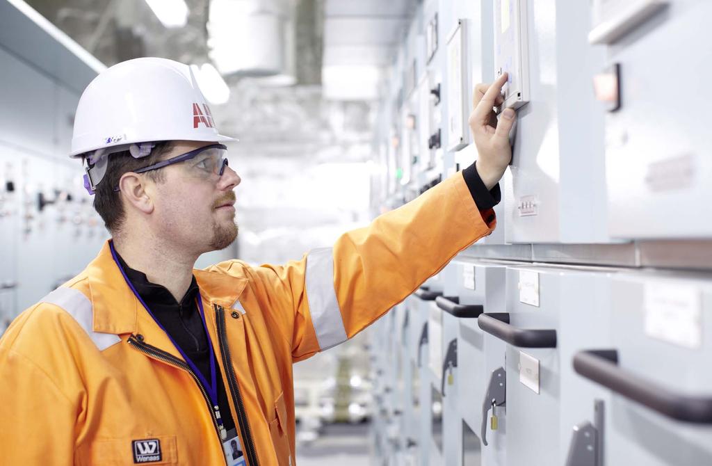
16 3. Electrical safety in medium voltage apparatus 3.1 Introduction The product Standard for medium voltage circuit-breakers is IEC EN , High voltage switchgear and controlgear, Part 100: Alternating current circuit-breakers. This standard is used in conjunction with Standard IEC EN : , High voltage switchgear and controlgear, Part 1: General specifications. The standard applies to alternating current circuit-breakers designed for indoor or outdoor installation and for operating at 50 Hz and 60 Hz frequencies in systems with voltage exceeding 1000 V. More specifically, it applies to three-pole circuit-breakers designed to operate in three-phase systems, single-pole circuit-breakers designed to operate in single-phase systems as well as the operating devices of these circuit-breakers and their auxiliary devices. With regard to safety, the standard prescribes that possible chemical substances potentially harmful for the environment should be indicated and that pressurized vessels must be designed and tested in accordance with the standard itself. In addition, the apparatuses must be equipped with adequate interlocks (indicated as the most reasonable system for avoiding human errors), while critical operations from the aspect of safety must be clearly indicated in the instruction manual so as to avoid the consequences of inappropriate operations. In the case of SF6 gas (sulphur hexafluoride) circuit-breakers and switch-disconnectors, ABB indicates, in the instruction manual, the presence of this gas, the environmental impact if is is accidentally dispersed and also states that any direct action involving the gas must be performed by ABB or by duly trained and competent personnel. 14


17 3.2 Interlocks Even though it is not a true interlock, the anti-pumping device is still a safety system that prevents the operator from performing critical operations. According to the definition given by the standard, it is a device that prevents autoreclosing after a closing-opening operation for as long as the closing command remains active. This prevents a continuous sequence of opening and closing commands from being given by mistake. In the case of ABB vacuum or SF6 circuit-breakers, interlocks are more or less a consequence of the relation between the assemblies of the switchgear unut or the relation between different functional units. However, the apparatuses be provisioned to allow for these interlocks to be created. For example: Protection of opening and closing pushbuttons: the opening and closing pushbuttons can only be used by means of a dedicated tool. Padlock holder for opening and closing pushbuttons: this device can hold one or more padlocks (up to three) so as to lock the opening and closing pushbuttons. Key lock for holding in the open position: several options are available, such as different keys to lock the same circuit-breaker or the same key for different circuit-breakers. When the lock is applied, the opening pushbutton remains depressed, thus preventing local and remote closing of the circuitbreaker. Locking magnet on closing mechanism: mechanically inhibits circuit-breaker closing if de-energized Locking magnet on truck: prevents the circuit-breaker from being racked into the switchgear if the auxiliary circuit socket is disconnected. Since the socket can be equipped with a rackingin lock for different rated current values, the locking magnet indirectly prevents circuit-breakers with lower rated current values than those envisaged in the functional unit from being racked in. This list is not exhaustive. Moreover, other interlocks are an intrinsic part of the circuit-breaker, as in the case of the anti-pumping device, and the interlock that prevents a withdrawable circuit-breaker from being connected or isolated when closed and from closing in the intermediate positions. The situation changes for multi-function apparatuses that combine the functions of circuit-breaker, switch-disconnector and earthing switch, since the interlocks are more complex. This is the case of ABB's HySec apparatus, which is a compact multifunction apparatus. 15


 Specially shaped lock which prevents the")
18 3. Electrical safety in medium voltage apparatus HySec is supplied with all the factorytested interlocks among the different functions, i.e.: Interlock between the feeder disconnector and earthing switch using two different, interlocked connection points Mechanical interlocks between the circuit-breaker function, line switchdisconnector function and earthing switch Provision for an interlock between the earthing switch and the connection compartment door of the switchgear's functional unit (always installed in case of UniSec HBC unit) Specially shaped lock which prevents the operating lever from being left in its slot 16


19 Key locks for locking the feeder disconnector and earthing switch in the open or closed positions (this accessory is an option when required for specific procedures). Both GSec and HySec must also comply with the standard governing current disconnectors and earthing switches, i.e. IEC EN , (CEI:17-83 Classification), High voltage switchgear and controlgear, Part 102: Alternating current disconnectors and earthing switches and with the one on switch-disconnectors, IEC EN , (CEI: Classification), High voltage switchgear and controlgear, Part 103: Switches and switch-disconnectors for rated voltages above 1 kv up to and including 52 kv. With regard to the classification established by the standard for partitions and shutters, the qualifying and exclusive characteristic of both HySec and switch-disconnector GSec is their PM-class lower metal half-casing. This means that these two apparatuses can be used to create class LSC2 or LSC2A panels (as described in the next chapter) offering maximum flexibility in case of maintenance. 17

20 4. Electrical safety in medium voltage switchgear 4.1 Introduction The product Standard for Medium Voltage switchgear is IEC EN : , High voltage switchgear and controlgear. Part 200: Metal-enclosed factory-built switchgear and controlgear for rated voltages above 1 kv up to and including 52 kv. This standard is used in conjunction with Standard IEC EN : , High voltage switchgear and controlgear, Part 1: General specifications. The previously mentioned enclosures can include fixed and removable components housed in compartments that can also be filled with fluid (liquid or gas) to provide insulation. The standard establishes many different categories of equipment with metal enclosures that differ in: the effects on continuity of service in the network when the equipment is serviced; the need for servicing the equipment and the ease with which maintenance can be performed Definitions Here are some of the definitions in the standard: metal-enclosed switchgear and controlgear switchgear and controlgear assemblies with an external metal enclosure intended to be earthed and completely assembled, except for external connections functional unit part of metal-enclosed switchgear and controlgear comprising all the components of the main circuits and auxiliary circuits that contribute to the fulfilment of a specific function. Functional units may be distinguished according to the function for which they are intended, for example: incoming unit, outgoing unit, etc. enclosure part of metal-enclosed switchgear and controlgear providing a specified degree of protection of equipment against external influences and a specified degree of protection against approach to or contact with live parts and against contact with moving parts high voltage compartment metal-enclosed switchgear and controlgear compartment containing high voltage parts, enclosed except for openings necessary for interconnection, control or ventilation. Four types of compartments are distinguished, three that can be opened, called accessible, and one that cannot be opened, called non-accessible interlock-controlled accessible compartment compartment containing high voltage parts, intended to be opened for normal operation and/or normal maintenance as stated by the manufacturer, in which access is controlled by integral design of the switchgear and controlgear procedure-based accessible compartment compartment containing high voltage parts, intended to be opened for normal operation and/or normal maintenance as stated by the manufacturer, in which access is controlled by a suitable procedure combined with locking tool-based accessible compartment compartment containing high voltage parts, that may be opened, but not for normal operation and maintenance. Tools are necessary for opening non-accessible compartment high voltage compartment that must not be opened connection compartment high voltage compartment in which electrical connections are made between the main circuit of the switchgear and controlgear assemblies and the external conductors (cables or busbars) towards the network or the high voltage switchgear and controlgear of the installation 18


21 The first two types of accessible high voltage compartment are available to the user and are provided for normal operation and maintenance. Corresponding covers and/or doors of these two types of accessible compartments do not require tools for opening. If a high voltage compartment requires tools for opening, then this is normally a clear indication that the users should take other measures to ensure safety and possibly to ensure performance integrity, for example, insulating conditions, etc. Lastly, in the case of non-accessible compartments, no user access is provided and opening may destroy the integrity of the compartment. This must be signalled by a clear do not open indication on the compartment. In some cases, non-accessibility is clearly determined by the construction design, e.g. a completely welded GIS (Gas Insulated switchgear) tank. Two examples of functional units are given below. The first is an outgoing functional unit with UniGear 550 switchgear circuit-breaker for primary distribution, while the second is an outgoing functional unit with UniSec switchgear switchdisconnector and fuses for secondary distribution. The different compartments can be distinguished in the two examples. A1 B D F G C A Circuit-breaker compartment A1 Switch-disconnector compartment B Busbar compartment C Cable compartment D Low voltage compartment E Gas exhaust compartment F Operating mechanism compartment G Fuse compartment 19


22 4. Electrical safety in medium voltage switchgear 4.3 Interlocks Allowing user access during normal operation is an enormous responsibility which, in the case of interlocking devices, lies with manufacturers of switchgear and controlgear. On the other hand, the purpose is to ensure a high level of safety for operators who must perform their tasks during the normal operation of the installation. Standard IEC EN requires provision for interlocks whenever there are operations that put safety at risk or even to simply make the switchgear and controlgear easier to use. These devices must also be sufficiently sturdy to withstand attempted incorrect operations without damage. In the case of main circuits, racking-in and racking-out circuitbreakers, switch-disconnectors or contactors must only be possible when they are in the open position. Their operation must only be possible when they are in the connected, isolated, withdrawn, test or earthing positions, but never in intermediate positions. Lastly, the interlock must prevent closing in the service position if these apparatuses are not connected to the auxiliary circuits associated with automatic opening or the apparatus itself. Vice versa, the interlock must prevent the auxiliary circuits from disconnecting when the circuit-breaker is closed in the service position. Make sure that disconnectors operate in the conditions for which they were designed. This means that the disconnector may only operate when the associated circuit-breaker or contactor is open. Since the short-circuit making capacity of earthing switches is less than the admissible rated peak current value of the circuit, they should be interlocked with the associated disconnectors. The photo alongside shows the interlock of functional unit SBC in UniSec switchgear between the earthed switchdisconnector and the earthing switch. The circuit-breaker compartment door is mechanically interlocked with the position of the earthing switches so as to ensure maximum safety conditions for operators who must work inside. Apparatus installed in main circuits, faulty operation of which can cause damage or which are used for securing isolating distances during maintenance work, shall be provided with locking facilities (e.g. provision of padlocks) (provision for a UniSec switchgear padlock is shown in the photo). If earthing of a circuit is provided by the main switching device (circuit-breaker, switch-disconnector or contactor) in series with an earthing switch, the earthing switch shall be interlocked with the main switching device. 20

23 If non-mechanical interlocks are provided, the design shall be such that no improper situations may occur if the auxiliary supply is absent. The following is a list of the interlocks provisioned in UniGear ZS1 switchgear. Some are provisioned by the standard and are therefore mandatory while others, such as the key interlocks on different functional units, depend on installation requirements. Types of interlocks Standard safety interlocks (mandatory) Type Description Required condition 1 A Apparatus racking-in/out Apparatus in "open" position B Closing of apparatus Truck in defined position 2 A Apparatus racking-in Multi-contact plug of racked-in apparatuses B Removal of multi-contact plug of apparatuses Truck in test position 3 A Closing of earthing switch Truck in test position B Apparatus racking-in Earthing switch in "open" position 4 A Opening of apparatus compartment door Truck in test position B Apparatus racking-in Apparatus compartment door closed 5 A Opening of line compartment door Earthing switch in "ON" position B Opening of earthing switch Line compartment door closed Note: The apparatuses are circuit-breakers and contactors. Keys (on request) 6 Locking of apparatus racking-in Key can only be removed if truck is in "withdrawn" position 7 Locking of earthing switch closing Key can only be removed if earthing switch is open 8 Locking of earthing switch opening Key can only be removed if earthing switch is closed 9 Insertion of racking in-out lever of apparatuses Key can always be removed 10 Insertion of earthing switch operating lever Key can always be removed Padlocks 11 Opening of apparatus compartment door 12 Opening of line compartment door 13 Insertion of racking in-out lever of apparatuses 14 Insertion of earthing switch operating lever 15 Opening or closing of shutters Locking magnets (on request) 16 Apparatus racking-in/out Magnet live 17 Opening/closing of earthing switch Magnet live 21

24 4. Electrical safety in medium voltage switchgear Lastly, the manufacturer must provide full information about the purpose and operating mode of the interlocking devices. The standard requires a series of demanding tests for interlocks, for the purpose of highlighting design defects and to check whether these can be overcome: 25 attempts to open any interlocked door or covering; 50 attempts to access or use the operating interface, when access or use is prevented by an interlocking device (shutter, selector lever, etc.); 50 attempts to operate the switching devices in the manual mode, when the operating interface is accessible; 10 attempts to manually operate the switching device in the wrong direction must be performed in addition to, and in any point of the sequence of 50 attempts described above; 25 attempts to insert and 25 attempts to withdraw the removable parts. The normal, manual crank handle operating mechanism must be used to perform these tests. The normally used operating forces must be doubled during the tests. Since interlock design-engineering, testing and operation are of critical importance, it is essential to rely on qualified manufacturers and, as far as possible, on factory-tested equipment. 4.4 Partitions and shutters The standard makes a distinction between partitions (part that separates a compartment from the adjacent ones) and shutters (part that can be moved from a position where it permits contacts, e.g. of a circuit-breaker, to engage fixed contacts, to a position where it becomes part of the enclosure or partition shielding the fixed contacts). It therefore defines two classes, depending on whether the switchgear/ controlgear has metallic partitions and/or shutters intended to be earthed, class PM, or has insulating partitions and/or shutters, class PI. 22


25 Class PM is the best choice for the safety of personnel working in the compartment, since it ensures that the structure is homogeneously earthed. The photograph illustrates the PowerCube solution showing metallic shutters, closed when the circuit-breaker is withdrawn and connected to the structure of the circuit-breaker compartment. 4.5 LSC categories The standard also defines the performance the functional units must provide by introducing the Loss of Service Continuity concept (LSC). It establishes four main categories defining the extent to which other compartments and/or functional units may remain energized when an accessible high voltage compartment is opened. Generally speaking, designers can adopt different LSC categories for different loads and, thus, functional units. For this reason, the Standard requires LSC classification as a mandatory rating plate data item. 23
26 4. Electrical safety in medium voltage switchgear The four LSC categories envisaged by the standard will now be analyzed in detail: LSC2, LSC2A, LSC2B and LSC1. Circuit-breaker compartment Disconnector / earthing switch Circuit-breaker compartment Disconnector / earthing switch Circuit-breaker compartment Circuit-breaker compartment Circuit-breaker compartment LSC2 category functional unit This form is intended to allow maximum continuity of service of the network during access to the high voltage compartments inside the switchgear and controlgear. This means that the accessible high voltage compartments in a functional unit can be opened while the other functional units in the same section remain energized. It implies that at least one busbar must be kept energized. Installation of a removable partition can be used to obtain this category. Category LSC2 requires that at least the connection compartment may be opened while keeping the busbar(s) energized. The standard defines two further categories (LSC2A and LSC2B) when LSC2 functional units have different accessible compartments (or apparatus) from the connections compartment. LSC2A category functional unit The category LSC2 functional unit such that, when an accessible compartment (other than the busbar compartment of switchgear or controlgear with one single busbar) is open, at least one busbar may be kept energized and all the other functional units of the switchgear/controlgear may be kept in service. In the example above, the disconnector is installed in the busbar compartment and there is complete segregation between the busbar compartment and the circuit-breaker compartment. Both the circuit-breaker compartment and the connections compartment can be opened safely with the busbar live after disconnector opening and closing of the earthing switch. The cables must be de-energized and earthed in order to access the circuit-breaker compartment. 24
27 Busbar compartment Disconnector / earthing switch Circuit-breaker compartment Circuit-breaker compartment Connections compartment LSC2B category functional unit This functional unit also corresponds to that of category LSC2, with the addition of other accessible compartments (or apparatuses). In addition to level of service continuity LSCA, the incoming high voltage connections (thus also the cable connections) to the functional unit may be kept energized when any other accessible high voltage compartment of the corresponding functional unit is open. The example above includes withdrawable switching devices. If the main switching device of each LSC2B switchgear and controlgear is fitted in its own accessible compartment, maintenance may be performed on this main switching device without de-energizing the corresponding cable connection. As a consequence, a minimum of three compartments for each functional unit is necessary in this example of LSC2B switchgear and controlgear: for the main switching device; for connection compartment for busbar compartment. Where more than one set of busbars is provided, each set must be in a separate compartment. LSC1 category functional unit Functional unit with one or more accessible high voltage compartments such that, when any one of these accessible high voltage compartments is open, at least one other functional unit may not be kept energized. The example above illustrates a functional unit of a circuitbreaker with cable connections in the same compartment as the circuit-breaker and busbar, which will therefore be classified as LSC1. 25
, thus able to ensure maximum continuity of service but with the degree of accessibility required for maintenance and servicing work: SBC")


28 4. Electrical safety in medium voltage switchgear The next figures illustrate 3 functional units in UniSec switchgear, all with high categories (LSC2, LSC2A and LSC2B), thus able to ensure maximum continuity of service but with the degree of accessibility required for maintenance and servicing work: SBC (circuit-breaker with switchdisconnector), SFC (switch-disconnector with fuses), WBC (unit with withdrawable circuit-breaker) and HBC. LSC2A LSC LSC2B Switch-disconnector 2 - Fuses 3 - Circuit-breaker 4 - Busbar compartment 5 - Operating mechanism compartment 6 - Circuit-breaker operating mechanism 7 - LV compartment for auxiliary circuits 8 - Cable compartment 9 - Metal shutters for panels up to 17.5 kv and insulating shutters up to 24 kv Alll UniSec switchgear units are equipped with metallic segregations and are thus in class PM (except unit WBC 24 kv which is PI class). 26

 switchgear Chapter 8 Guide to the selection of metal-enclosed switchgear and controlgear for service of standard IEC EN 62271-200 explains that, if the switchgear is")
29 UniGear ZS1 switchgear also comes under the LSC2B category since the busbar, circuit-breaker and connection compartments are physically and electrically segregated by metallic partitions, thus in class PM. In the example below, maintenance work can be performed on each of the two transformers while the rest of the switchgear may be kept in service. The metallic segregations are shown in blue, while the insulating material is in green. The gas-insulated parts are in yellow, while those in air are neutral in colour. 4.6 IAC (Internal Arc Classified) switchgear Chapter 8 Guide to the selection of metal-enclosed switchgear and controlgear for service of standard IEC EN explains that, if the switchgear is installed, used and serviced according to the manufacturer's instructions, the probability of an internal arc occurring is slight, but can obviously not be ignored. In order to provide an acceptable level of protection when a medium voltage electrical installation is designed and metalenclosed switchgear/controlgear is chosen, one must bear in mind that internal arc faults may occur owing to the specific context in which the switchgear/controlgear is installed and the operating modes/instructions issued to the personnel. Remember that the persons who transit in the vicinity of a substation are also classified as personnel. 27
30 4. Electrical safety in medium voltage switchgear Risk assessment (Based on defined limits of the assessment, intended use, and reasonably foreseeable misuse of a product) Risk reduction measures taken during design Step 1: Inherently safe design Step 2: Guards and protective devices Risk According to ISO/IEC Guide 51:2014 Safety aspects Guidelines for their inclusion in standards, the risk is a combination of the probability of occurrence of harm and the severity of that harm. Thus, to reduce the risk of internal arc, but not only that, a structured process (described in art. 6 of the ISO/IEC 51 Guide) should be implemented so as to obtain a tolerable level of risk, where the user also plays at active part in its achievement. The risk mitigation process must therefore include: a) an intrinsically safe design; b) protection and surveillance devices; c) detailed information for the user. Design Use Step 3: Information for use On the product or its packaging - warning signs, signals - warning devices In the instructions for use, including information or training (where necessary) Risk remaining (residual risk) after design Additional protective devices Training Organization of work, application of equipment and supervision Personal protective equipment Residual risk after measures applied by supplier Residual risk after all protective measures have been applied An intrinsically safe design is the first and most important step in the risk mitigation process. This is because experience shows that protective measures intrinsic to the product or system remain efficient over time, while the other steps (protections and information) can be removed or disregarded. This is why it is so important to choose intrinsically safe products, designed and made by manufacturers at the cutting-edge as to technological development and application of safety criteria to their products. This applies to all the previously mentioned issues concerning switchgear and controlgear, such as interlocking devices, accessibility levels, etc., but it is especially important when internal arc-proof switchgear is chosen. This solution also tends to preserve the integrity of things, buildings and activities by reducing the risk of fire outbreaks and the efficacy of one of the ignition sources. Lastly, the efforts made by those manufacturers have also led to a reduction in the size and weight of the switchgear now available with respect to the previous types. This means that less raw materials are used with reduced impact on the environment. As a guide to choosing the right switchgear with regard to internal arcs, one can affirm that only IAC-classified metalenclosed switchgear should be used where the risk is considered to be high. Generally speaking, an internal arc can be caused by different factors, such as: inadequate design, faulty installation, failure of the solid or liquid insulation (defective or missing), faulty operation, corrosion, faulty assembly, temperature rises due to loose connections, when withdrawable parts are racked in or out, ferroresonance, negligent maintenance, ageing under electrical stress, overvoltage, intrusion of small animals through cable input connections, etc. 28

31 The energy produced by an internal arc causes violent phenomena such as a sharp increase in internal pressure and temperature, acoustic and visual effects, mechanical stress to the structure of the switchgear, melting and evaporation of various different materials. These phenomena can lead to serious consequences for personnel present when the fault occurs, such as injuries from ejected solid parts and burns due to the emission of hot gas and incandescent particles. Thus, even when the metal-enclosed switchgear conforming to the provisions established by standard IEC EN has, in principle, been designed and built to prevent internal arc faults from occurring, the actual standard still defines an internal arc classification, i.e. provides a defined level of protection of persons when the switchgear is in normal service conditions. The classification must be indicated in the following way: Classification: IAC (Internal Arc Classified) Type of accessibility: A, B, C Classified sides of the enclosures: F, L, R Rated values of three-phase arc fault: current [ka] and arcing time [s] Rated values of single-phase arc fault (when applicable): current [ka] and arcing time [s] This designation must be indicated on the rating plate. The standard defines three types of accessibility to the enclosure of the switchgear in the installation site: Accessibility type A: restricted to authorized personnel only. Accessibility type B: unrestricted accessibility, including that of the public. Accessibility type C: accessibility restricted by installation out of reach and beyond the zone accessibile to the public. For type C, the minimum admissible distance of installation shall be indicated by the manufacturer. For accessibility types A and B, the sides of the enclosure that comply with internal arc test criteria are identified by the following codes: F for the front side L for the lateral side R for the rear side The front side must be clearly indicated by the manufacturer. Classified sides do not apply to switchgear with accessibility type C. Lastly, the rated arc fault currents (I a, I ae) must be defined for: three-phase arc fault current (I a); single-phase arc earth fault current (I ae), when applicable. When only a three-phase rated characteristic is specified, the pre-defined single-phase rated characteristic is 87% of the three-phase rated characteristic and there is no need to specify it and the rated arc fault time (T a, T ae). The normal values recommended for the arcing time of a three-phase arc fault (T a) are 0.1 s, 0.5 s and 1 s. IAC classification is proved by compliance with the following criteria (consult the standard for further details): Criterion No. 1 Correctly secured doors and covers do not open. Deformations are accepted, provided that no part comes as far as the position of the indicators or the walls (whichever is the closest) in every side. Criterion No. 2 No fragmentation of the enclosure occurs, neither are there projections of small fragments or other parts of the switchgear, up to an individual mass of 60 g. Criterion No. 3 Arcing does not cause holes in the classified sides up to a height of 2000 mm. Criterion No. 4 Indicators do not ignite due to the effect of hot gas or incandescent liquids. The indicators are pieces of black cotton fabric placed, on any classified side, on a mounting support at distances that depend on the type of accessibility (see figure). Criterion No. 5 The enclosure remains connected to its earthing point. 29
 for 12.5 ka arc fault current and 1 s arc fault duration.")


32 4. Electrical safety in medium voltage switchgear A few examples: UniSec IAC AFL 12.5 ka 1s switchgear; The switchgear is protected on three sides (front and lateral) for 12.5 ka arc fault current and 1 s arc fault duration. It is available in two versions: 1. Switchgear installed against the wall. In this case, the rear part of the switchgear and the wall form a duct through which gas can pass. 2. Switchgear not completely against the wall. In this case, filters installed in the rear part of the unit cool and lower the pressure of the gas before it is released into the environment. It is clearly forbidden to access the rear part of the switchgear when in service since it is not protected. UniSec and UniGear IAC AFLR 25 ka 1s switchgear; The switchgear is protected on four sides (front, lateral and rear) for 25 ka arc fault current and 1 s arc fault duration. Filters installed in each unit cool and lower the pressure of the gas before it is released into the environment. 30
33 4.6.1 Additional protection measures Standard IEC EN (sect ) establishes that other measures may be adopted in addition to the switchgear test, to provide the highest possible level of protection for persons if an internal arc occurs. These measures are aimed at limiting the external consequences of such an event. For example: rapid fault clearance times initiated by detectors sensitive to light, pressure or heat, or by a differential busbar protection; application of suitable fuses in combination with switching devices to limit the let-through current and fault duration; fast elimination of the arc by diverting it to metallic shortcircuit by means of fast-sensing and fast-closing devices; remote operation instead of operating in front of the switchgear. Fault rating [ka2s] ABB has technologically advanced solutions able to cover all the issues mentioned in the standard. For example, these solutions are able to detect and extinguish the arc by opening the fault feeder circuit-breaker in a selective way. Time is a critical parameter when it comes to reducing the effects of the arc since the energy emitted rapidly increases as time goes by. For example, an arc fault lasting 500 ms can cause serious damage to the installation. If the arc only lasts about 100 ms, the damage is often limited, while if it were to last less than 4 ms, the effects would be negligible. One must consider that the most important part of fault extinguishing time is due to the break time of the circuitbreaker, while the detector systems act in less than 15 ms. This means that the overall response can take less than 100 ms, so long as the circuit-breaker opens instantly and so long as this circuit-breaker is sufficiently fast. The result would be to reduce the thermodynamic effects of the fault, thereby limiting damage to the installation and making the event less dangerous. These systems generally use various types of pressure or flash sensors to very rapidly detect the effects of the internal arc and issue the command that opens the circuit-breaker involved. 300 Melting of structure components Melting of copper 200 Melting of cables Fault duration [ms] 31


34 4. Electrical safety in medium voltage switchgear Pressure detection system This system consists of pressure sensing devices installed on the top part of the switchgear, near the flaps that exhaust the hot gas generated by the internal arc. The shock wave caused by the pressure generated by the arc propagates very quickly inside the switchgear. This activates the sensing devices, which transmit the opening command to the circuitbreaker that feeds the switchgear. In this case, ABB proposes the ITH limiter: the pressure sensing device used is sensitive to small, sudden variations and features extremely rapid response times. It consists of contacts mounted on the upper end of each functional unit and possesses characteristics allowing it to be installed directly in the control circuit of the protection circuit-breakers. The contacts immediately generate a fault signal as soon as the overpressure flaps of the unit open owing to an internal arc. Since the contacts of the sensing devices are the maintained-position type, they act as a closing lock for the circuit-breakers they have opened. The typical trip time of these pressure sensing devices is 15 ms, to which the circuit-breaker break time should be added Flash detection system The first systems for detecting the flash produced by electric arcs date back to the beginning of the '90's. These systems used localized light sensing devices, which were installed in various points of medium voltage compartments to protect against internal arcs. After this, more than ten years later, second-generation systems appeared on the market featuring optical fiber flash detectors able to absorb the light along the entire length of the fibre itself. In this case, ABB proposes the REA system using these new detectors, since they possess undoubtable advantages. A B A) lth limiter B) steel pressure relief flap First, they cut down on installation costs since each fiber ring can be up to 60 meters in length and can be routed as required in the compartment to be protected. Secondly, since light absorption is distributed, there is no risk of the detector being obstructed in its view of the arc. Lastly, use of the ring configuration makes it very easy to perform autodiagnosis of the detector itself. In terms of safety against false triggering, the system only reads the lower part of the visible spectrum, including the ultraviolet spectrum. Secondly, the system is normally connected to current sensors installed in the main feeder units of the switchgear, which are used to instantly read the line and earth fault currents. 32
35 This allows the flash detector reading to be checked for correctness since both arc light and fault current are present during an internal arc fault. The system acts separately from the existing, conventional protection system and therefore does not need to be coordinated with the other protections. If the electrical system is complex with several feeders, selectivity can be obtained by several system units and by differentiating the path of the sensors. The typical tripping time is 2.5 ms, to which the circuitbreaker break time should be added. of events via GOOSE (Generic Object Oriented Substation Event), are able to considerably improve the way these interlocks are created and installed. An Ethernet LAN (Local Area Network) that covers the entire substation is used for the purpose and GOOSE communication transits on this support. Use of this system achieves an overall 30% improvement in operating speed compared to a conventional system of interlocks between switchgear relays. The interlocks are simply created by configuring the IEDs, while the autodiagnosis system detects any faults, which are identified immediately and then corrected. Apart from the Ethernet LAN cable, no other cabling is required between the units. Getting back to the internal arc protection issue, each of the units described above can be equipped with three flash detectors, one for each compartment. The IED that detects the arc flash transmits a GOOSE message, while the receiving IED of the feeder unit rapidly opens the relative circuit-breaker. The typical tripping time is 10 ms, to which the circuit-breaker break time should be added Arc detection by IED (Intelligent Electronic Device) In modern protection systems, certain intelligent devices called IED can be equipped with protection against electric arcs. ABB proposes relays REF615, RET615, REM615 and REF610, which can use lens sensors and create rapid, selective arc protection. Traditionally, protection systems based on cabled interlocks among various functional units are unable to ensure that internal arcs extinguish in time to limit the consequent damage. Modern systems using standard IEC Communication networks and systems for power utility automation and particularly rapid communication 33


36 4. Electrical safety in medium voltage switchgear Current limiting devices Fast breaking devices were developed during the second half of the '50's and are able to drastically limit short-circuit currents and their effects on the components of an electrical installation. These devices can detect and interrupt shortcircuit current at the very first rise by acting within a few milliseconds. This device basically consists of a part that supports the actual limiter insert, the protection current transformer and the electronic measuring and tripping device. If a fault occurs, the electronic device transmits an impulse via a transformer (in the supporting isolator) to the explosive charge in the insert. Following a small, controlled explosion, the main conductor opens and the current commutates through the parallel high rupturing capacity fuse, blowing of which first limits and then interrupts the current the first time it crosses zero. The current is constantly monitored by the external measuring system, which measures the derivative of current and is thus able to rapidly decide whether to trip the current limiter or not. In normal operating conditions, the parallel fuse and conductor combination allows losses to be kept to the minimum. In short, compared to other limiting devices, this solution keeps service losses down and efficiently limits short-circuit current on the load side. ABB has developed a device of this type called Is-Limiter. This device, which can be supplied in its own panel on a withdrawable truck, covers a wide range of voltage levels from 750 V to 36 kv and currents from 1250 to 5000 A. Is-Limiter is designed for use in a considerable variety of plant situations, the most interesting of which is installation as bus-coupler between two busbar systems supplied by two different sources. If the fault involves one of the two sources, Is-Limiter trips at the very first rise before the current is able to reach high levels. The voltage in the part of the system not affected by the fault only drops for fractions of a millisecond at most. Consequently, all the loads continue to be supplied. As can be seen in the example, the device trips so fast that there is practically no contribution from the second supply source. Thus the switchgear can be sized for a lower short-current value. By drastically limiting the let-through fault current and the duration of the fault itself, Is-Limiter falls within the additional protective measures indicated by the standard for limiting the effects of an internal arc. T1 160 ka 80 ka (*) l = l 1 + l 2 i l n = 31.5 ka k ln T2 l 1 l 2 = 31.5 ka k l n = 31.5 ka k perm. Single-line diagram of a bus-coupler for a system with l n = 31.5 ka k and with an l S - limiter i = i 1 + i 2 without I s -limiter Current i = i 1 + i 2 in the fault position i = i 1 + i 2 with I s -limiter l 1 l 2 (*) = (31.5 ka x χ x ) t 34


 system. UFES consists of a primary switching device and an electronic device.")

37 4.6.6 Ultra-rapid earthing system Among additional protective measures, an ultra-rapid earthing system is the fastest and most effective way to reduce the effects of an arc inside switchgear. This system includes the positive characteristics of the systems described previously, but is aso able to strongly limit the impact of the energy released by the arc in a very simple way, thus with a high cost/benefits ratio. The arc only takes a few milliseconds to extinguish and this allows the majority of the damages caused by the thermal and mechanical effects of the fault to be prevented. This sort of system provides evident advantages: drastic reduction in repair costs since the unit affected by the fault need not normally be replaced increased system and process availability since all that needs to be done is to eliminate the cause of the fault to restore service rapidly decidedly increased operator safety during normal use. In this case, ABB proposes the UFES (Ultra Fast Earthing Switch) system. UFES consists of a primary switching device and an electronic device. The switching device is embedded in epoxy resin and contains a moving contact pin set in motion at high speed by a magnetic repulsion effect generated by a Thompson coil. Vacuum Interrupter Operating mechanism Ceramic insulation Fixed contact Ceramic insulator Moving contact pin Rupture joint Piston Cylinder Moving contact system Micro gasgenerator These single-phase devices are typically installed in the incoming unit of each half-busbar, in the case of two incoming feeders where the installation is controlled by a normally open bus coupler, in an empty compartment or in a dedicated kit to install on top of the incoming unit, and can also be assembled in existing switchgear after small modifications have been made by the Service staff. 35
38 4. Electrical safety in medium voltage switchgear These devices operate in the following way: flash detectors in the compartments that need to be protected, send a signal to the monitoring unit to indicate that an arc is present. The monitoring unit transmits a closing command to the three fast operating mechanisms, which establish a three-phase dead-short to earth. The impedance of the dead-short is so low that all the current commutates to the new fault, causing the arc to immediately extinguish. After this, the fault current is interrupted by the circuit-breaker of the incoming unit. Typically, the arc takes 4 ms to extinguish. As can be seen in the graphs on the next page, the energy (green area) and pressure (light blue area) are considerably less than they would be authout UFES. 36
39 I (t) t TC Short-circuit current I n DC component Arcing time with UFES Definitive elimination of the fault current by circuit-breaker on supply side - 80 ms + x time Time for reaching tripping criteria Time in ms Over-pressure in bar t TC Pressure curve with UFES (4 ms) Pressure curve without UFES Time for reaching tripping criteria t TC + < 4 ms Time in ms It is estimated that the energy released is less than 1% of the energy released by the arc during a 1-second internal arc withstand test. Sometimes, not even the pressure and hot gas relief flap opens under these conditions. This solution is therefore suitable for enhancing the safety of existing, non-iac classified switchgear. 37


40 4. Electrical safety in medium voltage switchgear Remote operation The standard generically suggests remote control instead of operating in front of the switchgear. This paves the way to a vast array of solutions ranging from remote racking-in/out of circuit-breakers to remote supervision and control systems. Racking-in and out in older switchgear is performed by directly accessing the circuit-breaker with the door open. In such conditions, a failure or faulty operation when racking-in and out can lead to dramatic consequences for the operators. Creating controlled operating conditions with the circuitbreaker compartment door closed is therefore important for safety, especially when old circuit-breakers are involved since they are more liable to mechanical faults. Remote racking-in/out of circuit-breakers This function allows a certain distance to be maintained between the operator and the energy generated by an internal arc if a fault occurs in the switchgear. Operations on the circuit-breakers can then be performed in enhanced safety conditions. Racking-in/out a circuit-breaker with respect to the connected position are high-risk operations. ABB vacuum circuit-breakers can be equipped with an integrated motor-operated racking-in/out system. New switchgear can be outfitted with this device at the start, otherwise it can be installed at a later date by the Service staff. ABB Service proposes a closed-door motor-operated rackingin/out solution for old circuit-breaker retrofits that functions by remote control. Working when one is sure that no voltage is present is a further safety condition, regardless of any errors in communication with other operators or failures that may occur. This can be achieved by using a local voltage display. ABB has developed a product of this type based on the use of liquid crystal displays (LCD) which are sensitive to the alternating current field and do not require any auxiliary supply. The product is called VisiVolt and can also be installed in existing systems if voltage indicators were not provisioned when the installation was designed. 38

41 Supervision and control systems These systems improve safety in many different ways: for instance, apparatus, circuit-breakers, motor-operated disconnectors and contactors can be operated by remote control from a control room, thereby minimizing the risk of accidents for personnel. In addition, a series of interlocks can be planned by considering all possible plant situations, something that is very complicated to do by conventional methods. For example, such systems can take account of the different servicing situations, avoiding incorrect operations when operators are present in the installation. They can also keep all staff members informed by locally transmitting maintenance information to the technicians, etc. Safety interlocks in switchgear and functional units are obviously not replaced but integrated, thanks to an overall view of the functionality of the entire electrical installation. Different clearance levels can be defined for different actions, depending on their critical nature and their type of impact on the installation. For example, a motor can be started by a simple operator, while changes to the configuration of the installation would require a superior level of competence and authorization. 39


42 4. Electrical safety in medium voltage switchgear ABB offers tried-and-tested solutions in this particular field, such as the MicroSCADA systems, which ensure perfect integration with the various IED devices that protect and monitor the installation. Control center MicroSCADA Pro system server and workstation Remote communication IEC 101/IEC 104/DNP 3.0 Interbay bus IEC (ring configuration) MicroSCADA Pro communication gateway 40
43 41
44 5. Maintenance As described in the chapter dedicated to laws and regulations, Legislative Decree d.lgs. 81/08 Electrical plant and equipment, article 80 Employer's obligations establishes that, among other commitments, employers are obliged to provide operation and maintenance procedures able to ensure that the safety level achieved by implementing the measures adopted remains unaltered over time. As time goes by, negligent maintenance leads to the hazardous conditions that both the technical standards and manufacturers endeavour to limit by introducing rules and innovations when their products are designed and built. Maintenance is a vast subject and may range from assessments of the conditions of equipment and the likelihood of risk, to installation of advanced monitoring systems for condition-based maintenance. It may also include many other services, like training for site operators, on-call support in emergency situations, etc. The goal is always to guarantee the utmost reliability of the electrical installation over time. With reference to the diagram below, we have already seen how the operator's distance from the switchgear, reducing the duration of the fault and, thus, of the effects produced by an internal arc, contribute considerably towards reducing the risk of accidents. The other two issues to consider are awareness of the real conditions of the installation and staff training. Knowing the real conditions of one's installation means Voltage indicators Remote racking Distance Periodic measurements Y S T A E Condition F Time Equipment faults Short-circuits assessing the state of the switchgear/controlgear so as to establish a risk profile based on these conditions and their importance in the electrical network. Priority action areas can be defined on the basis of this analysis for the purpose of mitigating existing hazards and avoiding effective risk situations. The possible action areas include: risk monitoring and risk reduction programs to maximize reliability and reduce operator exposure to the minimum; switchgear/controlgear upgrading and retrofitting to enhance their intrinsic safety: maintenance activities based on state-of-the-art technologies, faster opening-closing cycles and troubleshooting procedures; diagnostic tests able to assess the quality of the connections and the effects of pollutants, mechanical failures and defective apparatus. When it comes to staff training and given that faults are very often caused by human error, it is evident that properly trained personnel are essential if correctly performed operations and, thus, operator safety are to be guaranteed. This issue includes true training, as well as the development of procedures and technical consultancy services: technical and engineering training services allow the operators to become more familiar with the switchgear and systems, thereby ensuring that they are operated in the right way; assessment of the risks associated with internal arcs helps to establish the type of personal protective equipment (PPE) that operators are required to use in the vicinity of potentially hazardous areas. They also help to define switchgear better able to limit and extinguish internal arc faults; technical consultancy services provide documentation about over-voltage and overcurrent due to transients associated with switchgear operation, as well as protection settings and coordination plus integration of relays and protection apparatus to ensure that the system functions as required when stressed by faults. Training Arc-faults 42


45 ABB Service offers all these services in the Power Care package, which can be customized to suit the customers' real requirements. The ABB Power Care framework is based on a matrix of services that cover five macro areas (1- Skills development services, 2- Emergency maintenance services, 3- Diagnosis and condition assessment services, 4- Selfmaintenance services, 5- Delivered maintenance services) and four service levels (entry level, level 1, level 2, level 3). The customer can choose the services he needs. When it comes to the effective maintenance of an electrical installation, the customer can choose from various different strategies. Obviously, failure to provide for maintenance is not a viable option since in the long run, it could expose the operators to the risk of accidents and the installation to damage. Other possible strategies are scheduled maintenance, preventive maintenance based on risk assessment and, lastly, maintenance based on continuous monitoring of the effective state of the installation. Continuous upgrading of the installation on the basis of technical developments in the sector would be an optimum solution worth considering. Scheduled maintenance is performed at planned regular intervals or according to criteria able to reduce the risk of faults and progressive deterioration of the installation. Maintenance work is generally organized on the basis of planned outage (putting out of service). Preventive maintenance is based on periodic analyses, measurements and tests performed in order to obtain information about the state of the installation, also considering the environmental, operating and process conditions of the switchgear/controlgear. The purpose is to obtain an overview of the state of the installation and an updated risk assessment allowing the most appropriate maintenance schedule to be defined. All switchgear/controlgear showing abnormal values can then be repaired or replaced, thus lengthening the useful life of the installation while ensuring high-level safety, reliability and efficiency. Maintenance based on continuous monitoring of the installation is certainly the most advanced type because it does not merely consider the real conditions of the switchgear/controlgear, but also allows the effectiveness of the corrective actions to be assessed. To achieve this, the operating parameters of the main components in the installation must be defined, continually monitored and compared with reference values. Maintenance is then performed by providing prognostic reports to indicate when the likelihood of fault occurrence is increasing. In the longterm, this strategy drastically cuts down on maintenance costs, while reducing the risk of faults and optimizing the use of available resources. Performance and reliability No maintenance Predictive maintenance Upgrading or retrofit solutions Risk-related and condition-based maintenance Repair Time Operation and reliability Risk based maintenance Preventive maintenance Corrective maintenance Fault impact 43

46 5. Maintenance ABB proposes MyRemoteCare and MySiteCare for this final application. MyRemoteCare can store diagnostic information about individual devices and uses it to generate reports and alarm signals. Log data and trend analyses allow deviations from standard behaviour over time to be determined. Not only does on-line monitoring enable ABB Service engineers to analyse the diagnostic data of the circuit-breakers, but also of low and medium voltage devices and transformers, predict faults, assess causes and undertake maintenance procedures at the right time. Maintenance managers can check out the tasks planned and performed by the ABB engineers by consulting the MyRemoteCare portal. The system acquires diagnostic information from various sources: IED, smart circuit-breakers, sensors and integrated diagnostic systems. When these devices are not available, ABB can provide MySiteCare, i.e. a universal circuit-breaker diagnostic unit. ABB Service specialists monitor the asset condition and define the right action Maintenance is planned in relation to the real asset condition Maintenance Responsible Substation 44

47 MySiteCare is a monitoring and diagnostic device that acquires information from circuit-breakers and processes it into diagnostic data for the purpose of determining the operating conditions and allowing maintenance to be planned. It can acquire the following information: mechanical data: opening and closing times, spring loading times, slipping and failed spring loading attempts, number of operations, idle time; environmental data, such as the temperatures in the functional unit compartments; diagnostic data, such as remaining life estimations and contact wear. The device processes predictive algorithms on the basis of these data and provides indications about the mechanical, electrical and functional conditions of the circuit-breaker. 45

,")

 and channel dedicated to safety.")

48 5. Maintenance MySiteCare has a user-friendly interface that displays the circuit-breaker state by means of a traffic light, where the colour indicates how serious the problem is and the probability of failure, its negative impact on availability or, worse still, on safety. No changes need be made to the switchgear, circuitbreaker or protection relay. The components that need to be installed include the central processing unit, the current sensor and wireless identification device (RDIF), which stores the circuit-breaker data and transmits them to the central unit. The predictive algorithms are configured by ABB engineers at the time of installation. The information processed by each MySiteCare device is transmitted via RS485 to a hub containing a SIM card for communication to the ABB Data center, via a mobile phone network (2g/3G..) and channel dedicated to safety. If there are no important events (which would be notified immediately), the state of the installation is updated every 24 hours, while the state of the connections to the installation are analysed to assess data quality and availability. ABB engineers can access the portal via the Internet so as to consult the diagnostic data and provide the required support. Information accessed via the Internet Alert via Brief periodic reports Transmission of diagnostic information from installation to MyRemoteCare 46

49 Lastly, switchgear/controlgear upgrading and retrofitting are further solutions to the problem of maintenance since they are able to adapt installations to state-of-the-art technology and safety levels. After thorough analysis of the state of the switchgear, complete replacement may be the most convenient option, rather than resorting to routine maintenance. For example, old circuit-breakers featuring obsolete technology (e.g. air or minimum oil circuit-breakers) can be replaced by modern SF6 or vacuum circuit-breakers for which solutions able to enhance operator safety have been implemented. In this case, the solution proposed by ABB is called OneFit: Integrally safe plug-in system Non-ABB panel Insulating system Basement Frame Shutter Door ABB breaker The new circuit-breaker is mechanically and electrically adapted following on-site assessment of the existing switchgear performed by expert engineers. The result is not only an improvement in performance (typical of new apparatus), but also and above all in safety thanks to solutions such as interlocks between circuit-breaker and door, remote controls, racking-in/out with the door closed and everything that modern technology provides as to protection and monitoring functions. 47

50 6. Conclusions Law No. 186 of 1 March 1968 established that electric and electronic materials, apparatus, machinery, installations and systems designed in compliance with the standards issued by the Italian Electrotechnical Committee are considered to be built in accordance with the best working practices. Establishing and requesting, right from the initial design phase, that the minimum requirements envisaged by the standards in terms of safety be applied to one's installation means starting out in the best of ways by reducing the risk of accidents. Relying on manufacturers with proven ability to comply with the standards, design, test and install innovative products and propose additional solutions that reduce the degree of risk to a further extent is the next essential step. Lastly, plant maintenance must be performed as required by law. What better than an all-round approach to the issue together with a reliable and proactive partner. 48
Medium voltage products UniSec DY800 New 24 kv air-insulated medium voltage switchgear to e-distribuzione specifications
 Medium voltage products UniSec Y800 New 24 kv air-insulated medium voltage switchgear to e-istribuzione specifications UniSec Y800 ubicles available Unit e-istribuzione specifications (Ed. 4) UniSec IS/1
SYSclad switchboard equipped with draw out type vacuum circuit breaker closed dooroperationoperation. SYSclad 12 17,5kV A.
 SYSclad switchboard equipped with draw out type vacuum circuit breaker closed dooroperationoperation 630 3150A SYSclad 12 17,5kV 16 31,5kA Generalities SYSclad is a medium voltage switchboard metal clad
Reviewed: DD Month University Code of Practice for Electrical Safety. PART B - Design and Construction of Electrical Equipment within the University
 Safety Office Reviewed: 17 July 2012 Reviewed: DD Month University Code of Practice for Electrical Safety PART B - Design and Construction of Electrical Equipment within the University The purpose of this
AIR INSULATED EXTENDABLE SWITCHGEAR UP TO 12KV GUIDE
 AIR INSULATED EXTENDABLE SWITCHGEAR UP TO 12KV GUIDE Certificate Number FM35831 APPLICATION Typical Uses and Classification The MSGair switchgear is used in transformer and switching substations mainly
Type SIMOPRIME A4, up to 24 kv, Air-Insulated Medium-Voltage Switchgear
 Circuit-Breaker www.siemens.com/energy Switchgear Type SIMOPRIME A4, up to 24 kv, Air-Insulated Medium-Voltage Switchgear s Technology Circuit-Breaker Switchgear Type SIMOPRIME, up to 17.5 kv, Air-Insulated
Unified requirements for systems with voltages above 1 kv up to 15 kv
 (1991) (Rev.1 May 2001) (Rev.2 July 2003) (Rev.3 Feb 2015) (Corr.1 June 2018) Unified requirements for systems with voltages above 1 kv up to 15 kv 1. General 1.1 Field of application The following requirements
DISTRIBUTION SOLUTIONS. GSec Gas-insulated switching and isolating apparatus
 DISTRIBUTION SOLUTIONS GSec Gas-insulated switching and isolating apparatus GSec is a three-position SF6 gas-insulated switchdisconnector designed for use in medium voltage switchgear for secondary distribution
MEDIUM VOLTAGE PRODUCTS. Powerbloc Pre-assembled modules for building medium voltage switchgear
 MEDIUM VOLTAGE PRODUCTS Powerbloc Pre-assembled modules for building medium voltage switchgear Powerbloc are the ideal solution for replacing fixed circuit breakers with withdrawable circuit breakers,
CPG.1 Gas insulated, single busbar cubicle range Up to 27 kv / 2000 A / 31.5 ka Up to 38 kv / 2000 A / 31.5 ka IEEE Standards
 Medium Voltage Switchgear Primary Distribution CPG.1 Gas insulated, single busbar cubicle range Up to 27 kv / 2000 A / 31.5 ka General description Presentation Ormazabal s CPG System includes the CPG.1
Steve Summers Region Sales Manager
 Steve Summers Region Sales Manager Institute For Animal Healthcare LV Switchgear Package Package Subs LV Switchboards PDU s LV sub Distribution MCC s MV Switchgear Established in 1972 manufacturing control
Circuit-Breaker Switchgear Type SIMOPRIME, up to 17.5 kv, Air-Insulated Medium-Voltage Switchgear.
 Circuit-Breaker Switchgear Type SIMOPRIME, up to 17.5 kv, Air-Insulated Medium-Voltage Switchgear www.siemens.com/energy Technology s Contents Application Page Benefits 2 Typical uses 2 and 3 Technical
UniSec Operation and maintenance manual
 Medium voltage products UniSec Operation and maintenance manual Safety 3 For your safety! 3 Skilled personnel 3 Critical messages 3 Contact us! 3 1. Introduction 4 1.1 General aspects 4 1.2 Operation and
INTERNATIONAL STANDARD
 INTERNATIONAL STANDARD IEC 62271-102 First edition 2001-12 High-voltage switchgear and controlgear Part 102: Alternating current disconnectors and earthing switches This English-language version is derived
Gas-insulated medium-voltage switchgear. For marine and offshore applications. Answers for energy.
 Gas-insulated medium-voltage switchgear For marine and offshore applications Answers for energy. Full power on the high seas This much is certain: whatever happens on the surface and on the floors of the
Our brand POWER DYNAMIC PASSION COMMITMENT CREATIVITY. A strong brand for strong products: 8PU Premium. MV Energy
 Our brand A strong brand for strong products: The ENERGOLINE brand represents our product portfolio of INDUSTRIAL SWITCHGEAR SYSTEMS. Our products are characterized by a high degree of safety, flexibility
VD4 Installation and service instructions kv A ka
 Medium voltage products VD4 Installation and service instructions 12... 36 kv - 630... 3150 A - 16... 50 ka Index For your safety! 1 I. Introduction 2 II. Programme for environmental protection 2 1. Packing
CPG.0 Single busbar gas-insulated cubicles
 MV Switchgear Primary Distribution CPG.0 Single busbar gas-insulated cubicles Up to 36 kv CPG System The quality of products designed, manufactured and installed by Ormazabal is underpinned by the implementation
Switchgear Type 8BT1, up to 24 kv, air-insulated. Medium Voltage Switchgear Catalog HA 26.
 www.siemens.com/medium-voltage-switchgear Switchgear Type 8BT1, up to 24 kv, air-insulated Medium Voltage Switchgear Catalog HA 26.31 2012 Answers for infrastructure and cities. R-HA26-013. eps Contents
Benefits, typical uses
 R-HA26-013. eps Switchgear Type 8BT1, up to 24kV,Air-Insulated Contents Application Page Application Benefits 2 Typical uses 2 and 3 Technical Data Ratings 4 Classification, dimensions, 5 room planning
NXPLUS C Single busbar. Maintenance-free for lifetime
 NXPLUS C Single busbar Maintenance-free for lifetime Energy Distribution Welcome! Page 2 Content Overview Technical data Typicals Panel design Circuit-Breaker panel Busbar Operation Metering Low-voltage
INTERNATIONAL STANDARD
 INTERNATIONAL STANDARD IEC 62271-200 First edition 2003-11 High-voltage switchgear and controlgear Part 200: AC metal-enclosed switchgear and controlgear for rated voltages above 1 kv and up to and including
INTERNATIONAL STANDARD
 INTERNATIONAL STANDARD IEC 60470 Second edition 1999-10 High-voltage alternating current contactors and contactor-based motor-starters Contacteurs pour courants alternatifs haute tension et démarreurs
MEDIUM VOLTAGE CE-B METAL CLAD SWITCHBOARDS. CE - B - C - en - REV
 MEDIUM VOLTAGE MEDIUM VOLTAGE APPLICATION CE-B Metal Clad switchboards are designed for use in public and industrial distribution system up to 24kV for the operation and protection of lines, generators,
OVERVIEW DESCRIPTION AND CHARACTERISTICS APPARATUS AND TYPES AVAILABLE SWITCHGEAR CHARACTERISTICS INSTRUMENT TRANSFORMERS MEASUREMENT SENSORS
 OVERVIEW DESCRIPTION AND CHARACTERISTICS APPARATUS AND TYPES AVAILABLE SWITCHGEAR CHARACTERISTICS INSTRUMENT TRANSFORMERS MEASUREMENT SENSORS PROTECTION AGAINST INTERNAL ARCS TYPICAL UNITS 3 Characteristics
ANNEX MOTOR VEHICLES AND MOTOR VEHICLES' PARTS. Article 1. General Provisions
 ANNEX MOTOR VEHICLES AND MOTOR VEHICLES' PARTS Article 1 General Provisions 1. This Annex shall apply to motor vehicles in UNECE vehicle regulations' category M1 as well as parts and equipment regulated
Key elements of the AS3000 Wiring standards and some of the recent changes.
 Key elements of the AS3000 Wiring standards and some of the recent changes. Dean of Engineering Steve Mackay Worked for 30 years in Industrial Automation 30 years experience in mining, oil and gas, electrical
ZX2 Gas-insulated medium voltage switchgear
 Gas-insulated medium voltage switchgear Double busbar 13 8 10 12 11 10 9 8 7 2 1 3 4 5 6 2 Versatile Partitioned single or double busbar system for all applications even with the most demanding parameters
10/2015 CUBICLE AND METAL-CLAD MEDIUM VOLTAGE SWITCHGEARS WEGA 07 WEGA 12 WEGA 17 WEGA 24 WEGA 36
 10/2015 CUBICLE AND METAL-CLAD MEDIUM VOLTAGE SWITCHGEARS WEGA 07 WEGA 12 WEGA 17 WEGA 24 WEGA 36 Gdańsk, October 2015 Improving the competitiveness of the company ELMOR through investments introducing
MEDIUM VOLTAGE CE-B36 METAL CLAD SWITCHBOARDS. CE - B36 - C - en - REV
 CE - B36 - C - en - REV.00 2011.9 EDIU VOLTAGE EDIU VOLTAGE APPLICATION CE-B etal Clad switchboards are designed for use in public and industrial distribution system up to 36kV for the operation and protection
GHA. Gas-Insulated Switchgear. Gas-Insulated Switchgear. Switchgear extension and replacement of a panel
 Gas-Insulated Switchgear GHA Gas-Insulated Switchgear Switchgear extension and replacement of a panel During this work, essential parts of the switchgear remain in operation No. AGS 535 066-01 Edition
Main switches in accordance with European standard directives
 Main switches in accordance with European standard directives N N ABB y ABB Switches in accordance with EU Directives New concept n order to dismantle technical barriers in commerce, the Council of the
HD4. Gas insulated MV circuit-breakers kv A ka
 HD4 Gas insulated MV circuit-breakers 12... 40.5 kv - 630... 3600 A - 16... 50 ka 1 DESCRIPTION Autopuffer breaking technique Electric arc extinction without chopped current No restriking after breaking
Level 3 Award in the Requirements for Electrical Installations BS 7671:2018 ( )
") Level 3 Award in the Requirements for Electrical Installations BS 7671:2018 (2382-18) March 2018 Version 1.0 FAQs 1 18 th Edition IET Wiring Regulations 2018 FAQs When will the 18 th Edition of BS 7671
Level 3 Award in the Requirements for Electrical Installations BS 7671:2018 (2382-18) March 2018 Version 1.0 FAQs 1 18 th Edition IET Wiring Regulations 2018 FAQs When will the 18 th Edition of BS 7671
ZX2.2 Gas-insulated medium voltage switchgear
 ZX2.2 Gas-insulated medium voltage switchgear 2 Brochure ZX2.2 Power engineering from ABB Solutions for the future As a technology group with global operations, ABB supplies the solutions of the future
E/ECE/324/Rev.2/Add.104/Rev.2 E/ECE/TRANS/505/Rev.2/Add.104/Rev.2
 28 September 2011 Agreement Concerning the adoption of uniform technical prescriptions for wheeled vehicles, equipment and parts which can be fitted and/or be used on wheeled vehicles and the conditions
8DJ. Maintenance-free for lifetime
 8DJ Maintenance-free for lifetime Energy Distribution Welcome! Page 2 October 1 st 2008 8DJ Main Applications for Medium-Voltage Switchgear Power generation Power stations G Power transmission High and
e 2 ALPHA Medium Voltage Switchgear K Catalogue EN
 e 2 ALPHA Medium Voltage Switchgear K-1.2.3 Catalogue EN WE CREATE IDEAS WITH POWER! ELEKTROMETAL ENERGETYKA SA provides solutions for electrical power engineering. Our services are carried out by a team
Gas-insulated medium-voltage switchgear. For the mining industry. Answers for energy.
 Gas-insulated medium-voltage switchgear For the mining industry Answers for energy. Full power even under extreme conditions Reliable All over the world, the demand for mineral resources is increasing.
the safe, reliable, and efficient choice for MV switchgear
 Power Xpert UX IEC Medium Voltage switchgear Tested to IEC 62271-200 17.5 kv up to 50 ka - 3 s 24 k V up to 25 ka - 3 s Air insulated switchgear Internal arc classified LSC2B-PM UX the safe, reliable,
MEDIUM VOLTAGE CE-B METAL CLAD SWITCHBOARDS. CE-B-C-en-REV
 CE--C-en-REV.04 2016.1 MEDIUM VOLTAGE MEDIUM VOLTAGE APPLICATION CE- Metal Clad switchboards family are designed for use in public and industrial distribution system up to 40,5kV for the operation and
SWITCHGEAR FOR SERVICE UP TO 36kV (CABLE AND OVERHEAD CONDUCTOR CONNECTED)
") PRODUCED BY THE OPERATIONS DIRECTORATE OF ENERGY NETWORKS ASSOCIATION Issue 3 2012 SWITCHGEAR FOR SERVICE UP TO 36kV (CABLE AND OVERHEAD CONDUCTOR CONNECTED) www.energynetworks.org 2012 Energy Networks
PRODUCED BY THE OPERATIONS DIRECTORATE OF ENERGY NETWORKS ASSOCIATION Issue 3 2012 SWITCHGEAR FOR SERVICE UP TO 36kV (CABLE AND OVERHEAD CONDUCTOR CONNECTED) www.energynetworks.org 2012 Energy Networks
Major changes within the New 18 th Edition Wiring Regulations announced by The IET
 Major changes within the New 18 th Edition Wiring Regulations announced by The IET BS 7671:2018 Requirements for Electrical Installations will be issued on 2 nd July 2018 and is intended to come into effect
Outdoor live tank SF 6. circuit breaker Type OHB for 24/36/40.5 kv applications
 Outdoor live tank SF 6 circuit breaker Type OHB for 24/36/40.5 kv applications ABB a global leader ABB is a global leader in Power and Automation technologies that enable utility and industry customers
UniGear. Technical Guide
 UniGear Technical Guide CONTENTS 0 CONTENTS 1.1 Compartments 1/2 1.2 Components of the structure 1/3 1.2.1 Hot-galvanized steel sheet 1/3 1.2.2 Painted steel sheet 1/4 1.2.3 Copper 1/5 1.2.4 Insulating
Consumer, Environmental and Health Technologies Biotechnology and Food Supply Chain. GUIDANCE DOCUMENT No. 1
 Ref. Ares(2016)5774004-05/10/2016 EUROPEAN COMMISSION Directorate-General for Internal Market, Industry, Entrepreneurship and SMEs Consumer, Environmental and Health Technologies Biotechnology and Food
Gas Insulated Metal-clad Switchgear, HMGS!
 Medium Voltage HMGS-G10 HYUNDAI Medium Voltage Gas Insulated Metal-clad Switchgear, HMGS! SF6 Gas Insulated Metal-clad Switchgear is an integrated assembly of vacuum circuit breaker, 3-position switch,
Voltage Rated operating voltage [kv] Rated power frequency withstand voltage [kv] Rated lightning impulse withstand voltage [kv]
![Voltage Rated operating voltage [kv] Rated power frequency withstand voltage [kv] Rated lightning impulse withstand voltage [kv]](/thumbs/80/82203973.jpg "Voltage Rated operating voltage [kv] Rated power frequency withstand voltage [kv] Rated lightning impulse withstand voltage [kv]") BasisBlock MC 1 Standards and Regulations IEC 62271-200 ; VDE 0671-200 ; BS EN 62271-200 Technical Data MC1-12 MC1-24 Voltage Rated operating voltage [kv] 12 24 Rated power frequency withstand voltage
BasisBlock MC 1 Standards and Regulations IEC 62271-200 ; VDE 0671-200 ; BS EN 62271-200 Technical Data MC1-12 MC1-24 Voltage Rated operating voltage [kv] 12 24 Rated power frequency withstand voltage
GUIDELINES ON ELECTRICAL SAFETY AT WORKPLACES
 MINISTRY OF LABOUR, INDUSTRIAL RELATIONS AND EMPLOYMENT GUIDELINES ON ELECTRICAL SAFETY AT WORKPLACES Occupational Safety & Health Inspectorate These guidelines should be used with approved standards:
Air-insulated switchgear UniGear type ZS1
 Air-insulated switchgear UniGear type ZS1 ABB Power Technologies / 1-7074 D 12-03-2003 - Air-insulated switchgear UniGear type ZS1 ABB Power Technologies / 2-7075 D 1 2-03-2003 - Rated voltage kv 12 17.5
Extract of the technical catalogue SACE Tmax XT New low voltage molded-case circuit breakers up to 250A
 Extract of the technical catalogue - 20.10 SACE Tmax XT New low voltage molded-case circuit breakers up to 250A Circuit breakers for power distribution Main characteristics SACE Tmax XT molded-case circuit
For your safety! Foreword
 Medium voltage products UniSec DY800 in accordance with Enel specifications Installation, service and maintenance instructions for 24 kv prefabricated assemblies with arc-proof metal enclosures and multi-function
ECOMP.3.A EUROPEAN UNION. Brussels, 12 December 2018 (OR. en) 2018/0220 (COD) PE-CONS 67/18 ENT 229 MI 914 ENV 837 AGRI 596 PREP-BXT 58 CODEC 2164
 2018/0220 (COD) PE-CONS 67/18 ENT 229 MI 914 ENV 837 AGRI 596 PREP-BXT 58 CODEC 2164") EUROPEAN UNION THE EUROPEAN PARLIAMT THE COUNCIL Brussels, 12 December 2018 (OR. en) 2018/0220 (COD) PE-CONS 67/18 T 229 MI 914 V 837 AGRI 596 PREP-BXT 58 CODEC 2164 LEGISLATIVE ACTS AND OTHER INSTRUMTS
EUROPEAN UNION THE EUROPEAN PARLIAMT THE COUNCIL Brussels, 12 December 2018 (OR. en) 2018/0220 (COD) PE-CONS 67/18 T 229 MI 914 V 837 AGRI 596 PREP-BXT 58 CODEC 2164 LEGISLATIVE ACTS AND OTHER INSTRUMTS
The Key Link for all your Distributions Needs. A Comprehensive Range for All Your Needs
 [ MV Air-insulated Switchgear Range ] 1 PIX CUSTOMER BENEFITS Compact, versatile and highly reliable designs Choice of vacuum or SF6 switching technology Wide range of applications Enhanced operator safety
B kv T&D GAS INSULATED SWITCHGEAR
 GAS INSULATED SWITCHGEAR B 105 170 300 kv The increasing demand for electrical power in cities and industrial centers necessitates the installation of a compact and efficient distribution and transmission
Official Journal of the European Union. (Non-legislative acts) REGULATIONS
 REGULATIONS") 10.1.2019 L 8 I/1 II (Non-legislative acts) REGULATIONS REGULATION (EU) 2019/26 OF THE EUROPEAN PARLIAMT AND OF THE COUNCIL of 8 January 2019 complementing Union type-approval legislation with regard to
10.1.2019 L 8 I/1 II (Non-legislative acts) REGULATIONS REGULATION (EU) 2019/26 OF THE EUROPEAN PARLIAMT AND OF THE COUNCIL of 8 January 2019 complementing Union type-approval legislation with regard to
Appendix: Safety and application notes for... 15
 Contents Safety... 2 Warnings... 2 Symbols used in this manual... 2 Operator s safety... 2 Avoid filter module damage... 2 DC-link resonance... 2 Description... 3 Description... 3 Ordering numbers, 380-415
Arc flash hazard mitigation
 Low Voltage Products Arc flash hazard mitigation Each year more than 2,000 people are treated in burn centers with severe arc flash injuries. ABB designs and manufactures products and solutions to provide
EMC 24 SERIES METAL CLAD SWITCHGEAR. We engineer, we assure. Up to 24 kv - 25 ka With Withdrawable, Air-Insulated, Medium Voltage Distribution Panel
 We engineer, we assure. EMC 24 SERIES METAL CLAD SWITCHGEAR Up to 24 kv - 25 ka With Withdrawable, Air-Insulated, Medium Voltage Distribution Panel Saudi Cable Company REF: EMC24-EN-16-04 2 www.elimsan.com
The University of New South Wales. School of Electrical Engineering and Telecommunications. Industrial and Commercial Power Systems Topic 2
 The University of New South Wales School of Electrical Engineering and Telecommunications Industrial and Commercial Power Systems Topic 2 SWITCHBOARDS Overview Also called Switchgear and Controlgear Assembly
e 2 ALPHA -2S Medium Voltage Double Busbar Switchgear K Catalogue EN
 e 2 ALPHA -2S Medium Voltage Double Busbar Switchgear K-11.1.2 Catalogue EN We Create Ideas With Power! e 2 ALPHA-2S double busbar switchgear is designed for use in primary and secondary electric energy
Medium-Voltage Switchgear OPERATING INSTRUCTIONS
 Medium-Voltage Switchgear Circuit-Breaker Switchgear Type NXAIR: Factory-Assembled, Type-Tested and Metal- Enclosed Switchgear for Indoor Installation, Air-Insulated Loss of Service Continuity Category:
ZX-Family Gas-insulated medium voltage switchgear
 ZX-Family Gas-insulated medium voltage switchgear Minimum overall costs ZX offers maximum economy The compact design of the panels reduces the space required and therefore the size of the station. Freedom
Power Systems PU. HYOSUNG Standard High-voltage Switchgear ProSWGR. Medium Voltage Metal-clad Switchgear
 Power Systems PU HYOSUNG Standard High-voltage Switchgear ProSWGR Medium Voltage Metal-clad Switchgear Power & Industrial Systems Performance Group Hyosung Power Systems has been continuously enhancing
TECHNICAL SPECIFICATION OF 11KV SF6 / VCB METAL ENCLOSED, INDOOR (PANEL TYPE) / OUTDOOR RING MAIN UNIT (RMU). (IEC standard equipment)
 / OUTDOOR RING MAIN UNIT (RMU). (IEC standard equipment)") TECHNICAL SPECIFICATION OF 11KV SF6 / VCB METAL ENCLOSED, INDOOR (PANEL TYPE) / OUTDOOR RING MAIN UNIT (RMU). (IEC standard equipment) 1 SCOPE OF SUPPLY This specification covers design, manufacture, shop
TECHNICAL SPECIFICATION OF 11KV SF6 / VCB METAL ENCLOSED, INDOOR (PANEL TYPE) / OUTDOOR RING MAIN UNIT (RMU). (IEC standard equipment) 1 SCOPE OF SUPPLY This specification covers design, manufacture, shop
Mod: KLD6-12/35XLAS-N
 12/2011 Mod: KLD6-12/35XLAS-N Production code: 1914070 INSTRUCTION MANUAL LOGIC LINE PLUS HOOD Reseller Stamp for Warranty Dear customer, Above all, thank you for choosing our product and we would like
Switchgear Type SIMOSEC, up to 24 kv, Air-Insulated, Extendable
 www.siemens.com/medium-voltage-switchgear Switchgear Type SIMOSEC, up to 24 kv, Air-Insulated, Extendable Medium-Voltage Switchgear Catalog HA 41.43 2012 Answers for infrastructure and cities. Neue Bilder
MESG 12 / 17.5 / 24 / 36 KV
 MESG 12 / 17.5 / 24 / 36 KV Medium Voltage Air Insulated Metal Enclosed Switchgear up to 36 kv- up to 1250 A - up to 25 ka for 1 sec. with SF6 or vacuum circuit breakers. 750 METAL ENCLOSED 1 1 ) GENERAL
This small footprint makes a BIG impact
 Power Xpert XGIS Gas-insulated medium voltage switchgear This small footprint makes a BIG impact Saving space is just one benefit of our gas-insulated switchgear. Big where it matters, small where it counts.
AF series contactors (9 2650)
") R E32527 R E39322 contactors General purpose and motor applications AF series contactors (9 2650) 3- & 4-pole contactors General purpose up to 2700 A Motor applications up to 50 hp, 900 kw NEMA Sizes 00
R E32527 R E39322 contactors General purpose and motor applications AF series contactors (9 2650) 3- & 4-pole contactors General purpose up to 2700 A Motor applications up to 50 hp, 900 kw NEMA Sizes 00
SLOVAK UNIVERSITY OF TECHNOLOGY Faculty of Material Science and Technology in Trnava ELECTRICAL ENGINEERING AND ELECTRONICS.
 SLOVAK UNIVERSITY OF TECHNOLOGY Faculty of Material Science and Technology in Trnava ELECTRICAL ENGINEERING AND ELECTRONICS Róbert Riedlmajer TRNAVA 2007 Unit 14 - Fundamentals of power system protection
 medium voltage switchgear manufacturer VACUUM CIRCUIT-BREAKER SWITCHGEAR TYPE SIMOPRIME, UP TO 17.5kV, AIR INSULATED MEDIUM-VOLTAGE SWITCHGEAR. UNDER LICENSE BY SIEMENS. www.simosynergy.com/simoprime VACUUM
Multi-Mover Charger for model L25
 Multi-Mover Charger for model L25 Important safety instruction. Keep these instructions. This manual contains important instructions for the safety of the user and the operation of the device. 1. SYMBOLS
General. Main electric circuits Fuses compartment Operating mechanisms Cables connection compartment
 General The switchgear must be suitable for 36 kv rated voltage and specifically conceived for the secondary distribution substations in M.V. with either ring or radial type networks. The switchgear must
The Impact of the 18 th edition (BS 7671:2018)
") The Impact of the 18 th edition (BS 7671:2018) In this article, Geoff Cronshaw looks at some of the proposed changes in the DPC (draft for public comment) for electrical installations, focusing on Section
The Impact of the 18 th edition (BS 7671:2018) In this article, Geoff Cronshaw looks at some of the proposed changes in the DPC (draft for public comment) for electrical installations, focusing on Section
MV Air Insulated Switchgear TAP17. Technical Data TGOOD
 MV Air Insulated Switchgear TAP17 Technical Data TGOOD 2017.1 Operating environmental conditions Place of installation: Indoor or outdoor Ambient temperature: 25 ~ +40 (higher or lower temperature optional)
SWITCHGEAR OPERATING PERSONNEL SAFETY UPGRADE SOLUTIONS FOR AGED INSTALLED BASE
 SWITCHGEAR OPERATING PERSONNEL SAFETY UPGRADE SOLUTIONS FOR AGED INSTALLED BASE Carlo GEMME Paola BASSI Giorgio MAGNO ABB - Italy ABB - Italy ABB - Italy carlo.gemme@it.abb.com paola.bassi@it.abb.com giorgio.magno@it.abb.com
& HIGH CURRENT DC POWER SUPPLIES INSTRUCTION MANUAL
 72-6850 & 72-6852 HIGH CURRENT DC POWER SUPPLIES INSTRUCTION MANUAL Table of Contents Introduction 2 Specification 2 Safety 4 EMC 5 Installation 6 Connections 6 Operation 7 Maintenance and Repair 8 www.tenma.com
UniSec Maintenance solutions
 DISTRIBUTION SOLUTIONS UniSec Maintenance solutions ABB supports you to improve the reliability, safety and efficiency of your electrical equipment UniSec Maintenance solutions Table of contents 004 00
GE Consumer & Industrial Power Protection. New. SecoGear kV Metal-clad Switchgear. GE imagination at work
 GE Consumer & Industrial Power Protection New SecoGear 12-24kV GE imagination at work General SecoGear metal-clad switchgear is designed and manufactured with advance technology and has been comprehensively
Power Xpert UX 36 High-voltage switchgear system. Reliable and safe for high performance applications
 Power Xpert UX 36 High-voltage switchgear system Reliable and safe for high performance applications A high-performance solution for high-voltage power distribution Eaton s Power Xpert UX 36 IEC high-voltage
EEA AGREEMENT - ANNEX XIII p. 99 APPENDIX 2 { 1 }
 9.2.2019 - EEA AGREEMENT - ANNEX XIII p. 99 APPENDIX 2 { 1 } DOCUMENTS SET OUT IN THE ANNEX TO REGULATION (EC) NO 1072/2009 OF THE EUROPEAN PARLIAMENT AND OF THE COUNCIL, AS ADAPTED FOR THE PURPOSES OF
24kV Medium Voltage Switchgear Metal-Enclosed (LSC2A)
") M6 24kV Medium Voltage Switchgear MetalEnclosed (LSC2A) GENERAL FEATURES GENERAL DESCRIPTION The structure of the cubicles, of considerable strength, has selfsupporting structure and is made of steel sheet
M6 24kV Medium Voltage Switchgear MetalEnclosed (LSC2A) GENERAL FEATURES GENERAL DESCRIPTION The structure of the cubicles, of considerable strength, has selfsupporting structure and is made of steel sheet
Hazardous areas, as found around a service station, are classified into three zones as follow: Table 1: Zone Classification for Vapours
 MIE TALK - July 2016 Compiled by Pieter H. Coetzee Introduction Far too many fires and burn injuries result from the careless or inappropriate use of petrol. Because petrol is so common in our environment,
Vmax Medium voltage vacuum circuit-breakers. IEC: kv; A; ka ANSI: kv; A; ka
 Medium voltage products Vmax Medium voltage vacuum circuit-breakers IEC:... 17.5 kv;... 1250 A;... 31.5 ka ANSI:... 15 kv;... 1200 A;... 31.5 ka The new Vmax circuit-breakers are the synthesis of ABB s
CEN and CENELEC Position Paper on the European Commission s proposal for a Directive on the deployment of alternative fuels October 2013
 CEN European Committee for Standardization European Committee for Electrotechnical Standardization CEN Identification number in the EC register: 63623305522-13 Identification number in the EC register:
(Non-legislative acts) DECISIONS
 DECISIONS") 14.5.2011 Official Journal of the European Union L 126/1 II (Non-legislative acts) DECISIONS COMMISSION DECISION of 26 April 2011 concerning a technical specification for interoperability relating to the
14.5.2011 Official Journal of the European Union L 126/1 II (Non-legislative acts) DECISIONS COMMISSION DECISION of 26 April 2011 concerning a technical specification for interoperability relating to the
GAE MCC Modular-C. Catalogue Standardized Motor Control Centres. PT Guna Era Manufaktura
 Modular-C\Standardized Motor Control Centres\ M600204.15 PT Guna Era Manufaktura Catalogue 2015 GAE MCC Modular-C Standardized Motor Control Centres General Definition Type-tested low-voltage switchgear
AIR INSULATED METAL ENCLOSED SWITCHGEAR AND CONTROLGEAR
 AIR INSULATED METAL ENCLOSED SWITCHGEAR AND CONTROLGEAR ANGLER SWITCHING DEVICES CONTENTS 1. General 2. Switchgear Types - Switch Disconnector - Disconnector 3. Cubicle Types - Cubicle with Switch Disconnector
voltage switchgear ZX ABB ZX Family 1
 Gas-insulated medium voltage switchgear ZX ABB ZX Family 1 ZX family general presentation Agenda Medium Voltage Switchgear Definition and application ABB Calor Emag in Ratingen Location, experience and
National Grid UK Electricity Transmission plc. NATIONAL SAFETY INSTRUCTION and Guidance
 National Grid UK Electricity Transmission plc NATIONAL SAFETY INSTRUCTION and HIGH VOLTAGE METAL CLAD SWITCHGEAR WITH SPOUTS Copyright National Grid plc 2014, all rights reserved. No part of this publication
E/ECE/324/Rev.2/Add.104/Rev.2/Amend.3 E/ECE/TRANS/505/Rev.2/Add.104/Rev.2/Amend.3
 26 July 2017 Agreement Concerning the Adoption of Uniform Technical Prescriptions for Wheeled Vehicles, Equipment and Parts which can be Fitted and/or be Used on Wheeled Vehicles and the Conditions for
Electric Vehicle Charging Safety Guidelines Part 2: Selection and Installation Edition DRAFT
 Date of publication: 1 November 2016Not yet published Issued by: Mark Wogan, Manager Energy Safety WorkSafe New ZealandNot yet issued Electric Vehicle Charging Safety Guidelines Part 2: Selection and Installation
PASS M00. Multifunctional modules for high voltage substations kv; A;... 31,5 ka
 PASS M00 Multifunctional modules for high voltage substations... 100 kv;... 2000 A;... 31,5 ka Innovation and on-going research The PASS M00 module is the latest arrival in the PASS family. PASS M00 is
Small craft Electric propulsion system
 INTERNATIONAL STANDARD ISO 16315 First edition 2016-03-15 Small craft Electric propulsion system Petits navires Système de propulsion électrique Reference number ISO 16315:2016(E) ISO 2016 ISO 16315:2016(E)
TECHNICAL SPECIFICATION
 IEC/TS 62257-7-3 TECHNICAL SPECIFICATION Edition 1.0 2008-04 Recommendations for small renewable energy and hybrid systems for rural electrification Part 7-3: Generator set Selection of generator sets
COUNCIL OF THE EUROPEAN UNION. Brussels, 11 December /3/06 REV 3 ADD 1. Interinstitutional File: 2003/ 0153(COD) ENT 84 CODEC 561
 ENT 84 CODEC 561") COUNCIL OF THE EUROPEAN UNION Brussels, 11 December 2006 Interinstitutional File: 2003/ 0153(COD) 9911/3/06 REV 3 ADD 1 T 84 CODEC 561 STATEMT OF THE COUNCIL'S REASONS Subject : Common Position adopted
COUNCIL OF THE EUROPEAN UNION Brussels, 11 December 2006 Interinstitutional File: 2003/ 0153(COD) 9911/3/06 REV 3 ADD 1 T 84 CODEC 561 STATEMT OF THE COUNCIL'S REASONS Subject : Common Position adopted
On_Disc. 2 o/c1 BS 7671 applies to a lift installations b highway equipment c equipment on board ships d electrical equipment of machines.
 1 PAPER 4 Sample Questions - C&G 2382 17th Edition full paper D 1 o/c 1 - A recommendation for the interval to the first periodic inspection shall be made by: a the installation electrician. b the main
AF series contactors (9 2650)
") R E32527 R E39322 contactors General purpose and motor applications AF series contactors (9 2650) 3- & 4-pole contactors General purpose up to 2700 A Motor applications up to 50 hp, 900 kw NEMA Sizes 00
R E32527 R E39322 contactors General purpose and motor applications AF series contactors (9 2650) 3- & 4-pole contactors General purpose up to 2700 A Motor applications up to 50 hp, 900 kw NEMA Sizes 00
CLP POWER HONG KONG LIMITED. SUPPLY RULES March 2001
 CLP POWER HONG KONG LIMITED SUPPLY March 2001 ADVISORY SERVICE Advice concerning matters relating to the supply of electricity may be obtained free of charge from the Company. OTHER COMPANY PUBLICATIONS
Switchgear Type SIMOSEC, up to 24 kv, Air-Insulated, Extendable
 Switchgear Type SIMOSEC, up to 24 kv, Air-Insulated, Extendable Medium-Voltage Switchgear Totally Integrated Power SIMOSEC Catalog HA 41.43 Edition Sept. 2014 Answers for infrastructure and cities. Neue