- 0 - UT Series Product Manual
|
|
|
- Beatrice Strickland
- 5 years ago
- Views:
Transcription
1 - 0 -
2 Congratulations on your purchase of this Quality Up-Lift Product! Before operating, please read this manual thoroughly and follow the safety rules closely. CONTENTS A INTRODUCTION 1. Product Schematic Diagram 2 2. Product Introduction 3 3. Technical Specifications.. 3 B SAFETY 1. Safety Rules Safety Decal. 5 C USING THE MACHINE 1. Preparation the Machine Operation of the Machine 8 3. Manual Lowering of Platform from Ground Controls Emergency Lowering Machine Achieving Optimal Performance. 11 D TRANSPORT 1. Loading & Unloading E OPTIONS 1. Dual Power Source Laser position indicator Hour meter F MAINTENANCE 1. Electrical System Use and Maintenance of Battery Hydraulic System Trouble Shooting
3 A INTRODUCTION 1. Product Schematic Diagram Typical UT Series Machine Schematic - 2 -
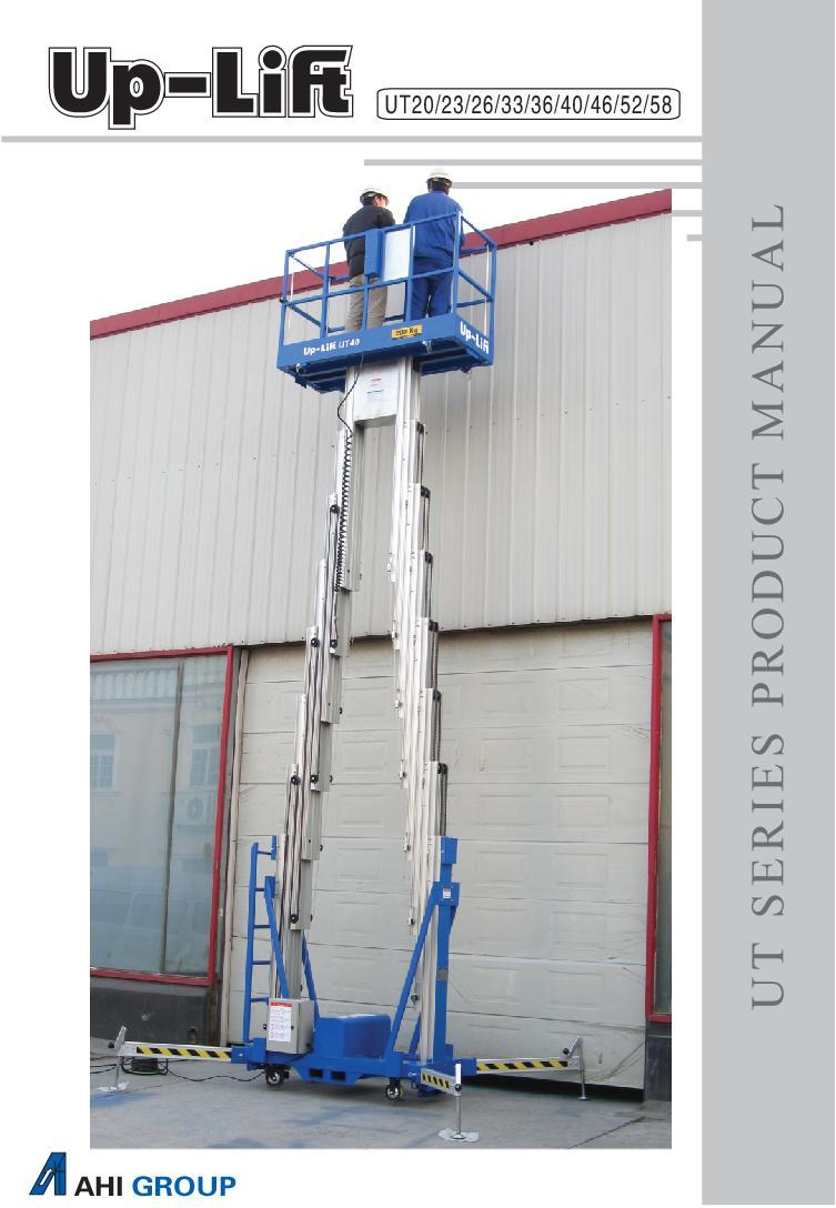
4 A INTRODUCTION 2. Product Introduction Up-Lift UT series elevating work platforms employ advanced technology and material, powered by a high quality hydraulic system and incorporates various safety measures to provide a higher capacity, safe and reliable aerial working unit. The components which make up the UT product are derived from proven quality sources, with key components sourced from quality European suppliers. The product is equipped with a number of advanced features. Lower height models have a patented back-up power feature allowing lowering of the platform during power black-outs. As a consequence, operators feel a greater sense of safety comparing with many similar products. Up-Lift UT elevating work platforms are extensively used for cleaning, decorating, maintenance and aerial signage work in hotels, restaurants, department stores, emporiums, shopping centers, airport departure lounges, sports stadiums, convention centers and stadiums, as well as factories, hospitals, universities and colleges. The smaller models are designed to pass through standard doorways and elevator lifts and are especially suited to small confined working space applications. 3. Technical Specifications Model UT20 UT23 UT26 UT33 UT36 UT40 UT46 UT52 UT58 Working height m Platform height m Load capacity kg Number of persons Power Source V 230/12 230/12 230/12 230/12 230/12 230/12 230/12 230/ Weight (AC) kg Weight (DC) kg N/A Stowed Height m Stowed Length m Stowed Width m Guardrail Height m Outriggers Footprint (LxW) m 2.1x x x x x x x x X3.8 The company reserves the right to alter its design & specification without prior notification

5 B SAFETY 1. Safety Rules All personnel should carefully read this warning sign and the instruction manual and follow the operating rules. Failure to do so could result in serious safety hazard. NEVER try to move the machine while platform is loaded or with the outriggers installed. NEVER elevate the platform in windy environments. This machine is designed for non-wind conditions. NEVER operate the platform if the level indicator shows the machine is not on a level position. This machine is designed to be elevated when the chassis is level. ENSURE that the outriggers are on firm solid ground. NEVER sit on, stand on or climb over the platform top-rail or mid-rail to conduct aerial work. NEVER use ladders, planks or other devices to increase the height of the platform. NEVER exceed the load limit specified for the machine. NEVER use machine as a goods lift or a people mover. ENSURE that no person or object is placed beneath the platform before and during operation of the machine. NEVER move the machine into overhead beams or objects. NEVER operate the machine while under the influence of alcohol. NEVER operate the machine under poor lighting conditions. NEVER operate the machine within proximity of power lines, or use as an earth for welding. Electrical shock can kill you. This machine won't protect you from shock

6 B SAFETY 2. Safety Decal Warning decals form an important part in the safe operation of a machine. It is the responsibility of the operator to inform the owner if the decals are missing or are in poor condition
 Control Panel Platform Control Panel 1.")


7 C USING THE MACHINE 1. Preparing To Use the Machine 1(A). For models UT20 to UT52 Main (Gound) Control Panel Platform Control Panel 1. Move the machine to the location where aerial working is required. 2. Connect power supply to the unit. Turn the key-switch to the "PLATFORM" position. Power supply indicator red light will light up. 3. Install the four outriggers and position these supporting legs on firm ground surface (Fig 1A). Before operating the unit, check that the bubble in the spirit level indicator is centered within the black circle (Fig 1B) and all four outrigger indicator lights on the base control box are lit up. If required adjust the outriggers until the bubble in the spirit level indicator is centered within the black circle, the machine is now leveled for use. 4. Preparing to use the Platform Cage from its stored position Follow the steps below to raise the cage from its stored position and secure for use. a. Open the ground control panel and switch the key switch to the PLATFORM position. Check that all 4 outrigger safety switches are lit. Refer Fig 2 For DC model, turn the Multi-function switch on the DC box to the ON position before proceeding to the next step. Refer Fig 3 b. Depress the Red ascending button on the left side of the ground control panel. Refer Fig 2 Allow the platform to ascend slowly JUST above the support brackets located on the two sides of the masts. Refer Figs 4 & 5. Fig 1A Fig 1B Fig 2 Fig 3 Fig 4 Fig 5-6 -

.")


8 c. When the platform is JUST above the two support brackets, pull out each of these support brackets ready for the platform to sit on. Refer Fig 5 d. Once this is ready, depress the descend button on the ground control panel. This will lower the platform until it is sitting on the pin boss, allowing the pin to be inserted and secured in position with the split pin provided. Refer Figs 6 &7. e. The Platform is now ready for operator use. 1(B). For Model UT58 Main (Ground) Control Panel Fig 6 Fig 7 Platform Control Panel NOTE: Before moving the UT58 machine using the motorised drive wheel, check that the charge meter on top of the drive motor control cabinet is full (see Figure 1A). To charge the 2 x 12V batteries, (refer to Figure 1B), set the RED isolating switch ON. This connects the charger to the batteries. Using the power cord, connect the charger to an external V AC power supply. When the LED2 light turns green, the batteries are fully charged. Switch off the RED charging isolator switch. Remove the power cord and store securely. Fig 1A Isolating switch Charge meter First move the machine to the work location. A. Drive Wheel Operating Instructions CAUTION: TURN SLOWLY TO MOVE THE MACHINE. DO NOT SPEED. Fig 1B B. Engage on the drive motor power switch on the chassis of the machine (Fig2). From the motor control handle, turn the key Fig2-7 -
, ensure that the floor is flat and firm. C.")

 external outriggers until these are taking load and the four (4) outrigger lights are all lit up on the ground control panel. Refer Figs 3.")
 locking pins to allow the cage to be raised.")
9 switch ON and gently twist the red knobs in the forward direction to move the machine forward and vice versa to more the machine backwards. To stop the machine in an emergency, press the centre red button. Once the machine is moved to the desired position (check using the laser position locator), ensure that the floor is flat and firm. C. Connect the machine to V AC external power using a 15 Amp supply and power cord of less than 20 metres. Switch 'ON' the key switch on the ground control panel. Release the emergency button so the power source red light is on. D. Set the 4 outriggers on the chassis first, one by one, checking the spirit level indicator and making sure that the wheels are detached from the ground. Next swing out the four (4) external outriggers until these are taking load and the four (4) outrigger lights are all lit up on the ground control panel. Refer Figs 3. WARNING: Check that the spirit level bubble is centred within the circle. (Refer page 6) E. Raise the cage from its stored position (refer Fig 4). With the cage in its stored position, release the four (4) locking pins to allow the cage to be raised. On the side of the ground control panel, depress the red ascending button until the cage is raised by at least 1.2 meters, then swing open the support brackets (on both ends). Lower the cage until it rests on the two support brackets (Fig 5). Insert the four (4) locking pins to lock the cage in position. Refer Fig 6. The machine is now ready to commence work. Red ascend button Fig3 Fig 4 Support bracket Fig5 2. OPERATION OF THE MACHINE 2 (A). For Models UT20 to UT52 1.The operator can now use the ladder provided to access the platform by lifting the mid-rail on the access side and drop close the mid-rail. 2. Once inside the platform, depress the "UP" and "POWER" buttons simultaneously to raise the platform. When the required height is reached, releasing pressure on both buttons will stop the platform. Operator can now commence aerial work. 3. After completion of work, check the space below the platform is clear before depressing both the "DOWN" and "POWER" buttons simultaneously to lower the platform to the minimum height position. Releasing the pressure on these buttons STOPS the platform. 4.To return the platform cage to the stored position, follow the instructions under 4 above in REVERSE order (from step 4 (d) (remove pin from boss), step (c), (b), back to step (a) switch off the multi-function switch to OFF). This is described as follows: Fig6-8 -
10 C USING THE MACHINE First, unlock and remove the pins from each of the sockets. Press the Up button on the ground control panel to lift the cage slightly until the base of the guide rails is separated from the support brackets. Fold back the two support brackets and lower the platform cage down to the lowest position. 5. Detach the outriggers and return to outrigger pockets provided. Finally move the machine to a dry storage area. WARNING 1. Never move the machine unless the platform has returned to the lowest position. 2. Never use the machine as a welding earth 3. After operator has completed work, return the outriggers to its stored position. 4. Return the key switch to the OFF position and remove the key for safe keeping. 5. If AC power supply is cut while the machine is in the elevated position, the electrical system will automatically switch over to the backup power supply allowing normal operation of the unit to reach the ground level position. 6. For DC system, always charge the battery when the charge level as shown on the battery charge meter, drops to 70%. To charge, set the Multi-function switch to the CHARGE position and connect to power supply. NB: As the machine is similar in design to single mast machines with the mast columns being held tightly in between by bearing blocks, new machines are expected to produce friction noises while the platform is raised. Overall noise is generally within 70 decibels. 2 (B). For Model UT58 A. The operator can now enter the platform cage by lifting the entry gate bar. To operate the platform controls, depress the UP & POWER buttons simultaneously to ascend. To descend, depress the DOWN & POWER buttons simultaneously. Use the Emergency stop button to cut the power supply in an emergency. B. The following procedure should be undertaken to return the cage to its stored position after completion of work. With the platform at its lowest position, release the four (4) locking pins. Depress the red ascending button located on the side of the ground control panel until the platform s cage is raised slightly above the two (2) support brackets. Fold back the two (2) support brackets and lower the platform s cage to its stored position by depressing the DOWN button on the ground control panel. Lock the four (4) locking pins. Raise the chassis outriggers off the ground and move the external outriggers to the sides of the chassis. Switch the ground control s key switch to the OFF position. Remove key. Move the machine to a dry storage area. Switch the key switch from the drive wheel motor to the OFF position. Remove key
11 C USING THE MACHINE NOTE: 1. WARNING Never move the machine unless the platform has returned to the lowest level. 2. WARNING Never use the machine as a welding earth. 3. The platform can be lowered during a power failure by opening the emergency down valve slowly. Once the platform reaches the stored position, retighten the emergency down valve. 4. If the drive motor s battery voltage is low, charge the battery immediately. Never allow the charge to fall below 70 %. 5. As the UT58 machine is similar in design to single mast machines with mast columns being held tightly in between bearing blocks, new machines are expected to produce friction noises while the platform is raised. Overall noise is generally within 70 decibels. 3. Manual Lowering of Platform from Ground Control Check that the key switch is in the "OFF" position. Twist the Emergency Stop button clockwise to release to on position. Switch and hold the key switch to "GROUND" position, press the Down button to lower the platform. For UT58S, switch the key switch to the ON position and press the Down button. 4. Emergency Lowering The emergency down valve is located between the masts on the hydraulic system. To lower the platform, the red dial is turned anti-clockwise. The lowering speed is dependent on the number of turns of the dial. Return the dial to the closed position prior to re-using the machine. Caution must be taken to control the speed of descent. Make sure that no one is beneath the platform
12 C USING THE MACHINE 5. Machine Achieving Optimal Performance 1) The standard unit is suitable for indoor operation and the operator should as far as possible operate the machine indoors. 2) If the machine is used outdoors, care should be taken to ensure that the ground is firm and solid to prevent instability. Avoid operation under any windy condition. 3) Always check that the outrigger position indicator lights are operating correctly. 4) Descent at full height: When the platform is loaded and raised to its highest point, momentarily press the platform control s POWER and DOWN buttons simultaneously. Then fully engage these two buttons to continue the descent. This minimizes the impact to the equipment of a change in hydraulic flow direction. 5) Before using the machine for aerial work, raise the platform slightly without load to ensure normal functioning of the machine. 6) Frequent checks should be made of the electricity leakage protection to ensure effectiveness. 7) For maintenance requirement of the hydraulic system, please refer to Section F3 (C.) 8) If the machine is used frequently, routine maintenance and safety checks should be carried out every 3 months. 9) Regular check of the chain-drive system for wear and tear at least on a quarterly basis. Apply N32 oil on chain friction points as well as wheels points as required. 10) Keep machine away from dust and rain. Never store the machine outdoors or in an area of high humidity or heat. During storage, keep the machine covered with a protective cover. 11) Only qualified professionals are allowed to dismantle any part of the machine or conduct maintenance on the machine. If unsure, please contact supplier
.")
. (Make sure that the machine s weight does not fall on the cage rail).")
13 D TRANSPORT 1. Loading & Unloading Step1: Move the machine from the pallet to firm and level ground. Cut the steel bands which tie the machine onto the timber base. Remove any timber protective structure around the machine. Dismantle any timber blocks placed against the castor wheels of the machine for protection during transport. (Refer Fig.1). With a fork lift, lift the machine from its timber base using the machine s fork lift pockets and place it on the floor (Refer Fig 2). Alternatively, use a hoist or overhead crane to lift the machine with a sling. (Refer Fig 3). (Make sure that the machine s weight does not fall on the cage rail). Gently lower the machine to the floor. Step 2: Insert the outriggers onto the machine and adjust them to ensure the machine is level. (Check spirit level indicator). Study the product manual carefully before connecting to a power source. Switch the key switch on the main control panel to the PLATFORM position. For the UT58 machine switch the key switch on the main control panel to the ON position. The machine is now ready for a trail run. (Refer Section 4) WARNING: - To avoid damage when unpacking, extreme care should be taken with the Mast Cover and Cage. Also with the Upper and Lower Control Boxes. - The unloading procedure must be strictly followed. Incorrect handling may cause serious machine damage and personal injury. UT
14 E OPTIONS 1. Dual Power Source means either External AC supply source or AC source from DC battery & inverter pack. CHARGING PROCEDURE: Using the power cable supplied in the cable storage compartment, connect directly to a V AC external power source. Set CHANGE-OVER-SWITCH to CHARGE position. Charging is complete when charger LED indicator light is green. After charging, set the CHANGE-OVER-SWITCH to the OFF position. Store the power cable inside cable storage compartment.. (For battery maintenance, refer to section F2.) AC OPERATION FROM INVERTER OUTPUT: Connect AC power plug from the hydraulic motor to inverter V AC output socket. Set the CHANGE-OVER-SWITCH to the ON position. Commence normal operation. After completion of work, set the CHANGE-OVER-SWITCH to the OFF position. Disconnect the machine s AC power cable from the inverter Output Socket. Store the portable power trolley in a clean, dry and ventilated area. AC OPERATION FROM EXTERNAL V SUPPLY SOURCE Connect the hydraulic motor s AC power plug to a 220/240VAC power source. Commence normal operation. After completion of work disconnect the hydraulic motor s AC power plug from the power source


15 E OPTIONS 2. Laser Position Indicator Push the machine to the location beneath where aerial working is required. 2. Press the button on the side of the laser position indicator inside the platform. 3. Check the spot where the laser beam is directed to see if this is within the desired working area. 4. If the laser beam is outside the desired working area, adjust the machine position so that the laser beam shines within the working area. WARNING: NEVER LOOK INTO THE LASER BEAM, Remove cap on the outlet to check work position. Replace cap immediately after use to avoid harm to eyes. 3. Hour Meter An optional hour meter can be used to record the number of hours the machine has been used (based on the time the key switch is on). This usage record helps in determining the need for maintenance service. Hour Meter
16 F MAINTENANCE 1. Electrical System Note: Repairs by unauthorized personnel may result in serious personal injury or death. Any interference with and electrical the hydraulic system may also invalidate the product warranty
17 F MAINTENANCE 2. Use and Maintenance of Battery ( DC Models) When transporting the DC powered personnel lift, the battery casing and battery should be detached from the rear of the machine to prevent damage to the battery casing. To prepare the machine for use, install the outriggers, then load the battery box (including battery inside) onto To charge the battery, follow instructions located on the machine. When the charger indicator changes from red to green, the battery is fully charged. Continue charging for about an hour or more, this will ensure maximum performance of the battery. If the charged battery has been used or left unused for a period of time, recharging is required, as prolonged storage at low charge will result in reduced battery performance Store the battery in a cool and dry area to reduce the loss of power during storage period. An Absorbed Glass Matt (AGM) maintenance free battery is used. AGM batteries do not include fluid so unlike Lead Acid batteries they not require the battery s fluid level to be checked. Check the battery and the terminals regularly to ensure they are secured tightly in position. Inspect the insulation casing for worn spots, cracks or broken terminals and repair them immediately. To connect the battery and the charger, set the power switch to the "OFF" position. Ensure that the positive terminal on the battery is connected to the positive socket of the charger and vice versa. To commence charging set the power switch to the ON position. Charging must be carried out in a well-ventilated area, away from inflammable materials as charging may result in sparks or flames, which may result in an explosion. Ensure the connecting socket on the battery casing is properly maintained to avoid power disruption. Keep batteries fully charged when in storage. Prolonged storage at low charge will result in reduced battery performance. Disconnect the battery from the machine prior to long term storage. Store in a cool dry place. The battery casing carrying the charger contains an ammeter, which indicates the charge rate. All power usage should stop and the battery recharged, when the power discharge level indicated by the ammeter reaches 70%. This is strongly recommended to ensure maximum battery life. WARNING Do not charge batteries under direct sunlight or near heat generators. Battery should be charged immediately after use. If battery is stored without recharging, performance could deteriorate. Avoid operating the battery below - 5 C (5 F) or above 50 C (122 F). Batteries are heavy and should be handled accordingly. Never disassemble a battery. Clean with moist soft cloth. Never dispose of a battery into fire. Recycle all used batteries. Do not short the battery terminals
18 F MAINTENANCE 3. Hydraulic System (A) Operating Principle schematic diagram Legend: 1. Uni-directional Valve 2. Relief valve 3. Flow Restrictor 4. Solenoid Valve 5. Oil Cylinder 6. Hydraulic Pump 7. Filter 8. Motor 9. Explosion relief valve 10. Oil Reservoir Once the hydraulic pump s motor is switched on, the pump will deliver a high pressure oil flow into port P of the valve block (shown as dotted line). The unidirectional valve 1 allows the oil to flow out via Port A and into the hydraulic cylinder. This raises the platform slowly. The relief valve 2 is adjusted to by-pass oil when the rated capacity is reached. This prevents operation beyond the pre-set capacity rating. When the operator calls for the platform to descend, solenoid valve 4 is energized, oil from the hydraulic cylinder then flows back to the valve block via Port A (The unidirectional valve 1 prevents oil flow through port P). Oil flow can only pass through solenoid valve 4 onto the flow restrictor 3 and out of the valve block through Port 0 into the oil reservoir 10. This allows the platform to descend slowly. Due to the pressure balancing design of the valve block, the ascending and descending speed is not affected by the platform capacity changes. (Refer Fig 6.1) (B) UT58 Operating Principle schematic diagram UT58 comprise of two set of hydraulic systems powered by M1&M2 respectively and covers the two groups of masts. M1 is the hydraulic motor which drives the lower four (4) sets of masts, these 4 lower masts move in synchronism as the 4 hydraulic cylinders rise. M2 is the hydraulics motor which drives the upper (2) sets of masts powered by two hydraulic cylinders. Ascend control: Depressing the ascend and power button, starts the M1 motor driving the four (4) hydraulic cylinders and the corresponding masts to its maximum position governed by the limit switch. At this point, the M1 motor is de-energized, and the M2 motor is energized. The M2 motor drives the upper series of masts, until these reach their maximum position as defined by its limit switch. This stops the M2 motor and the maximum platform height is attained. Descend control: - Depressing the descend and power buttons, first energizes the lowering hyraulic solenoid allowing the upper series of masts to descend. When this upper series of masts reaches their lowest position as determined by the limit switch, the limit switch then energizes the hydraulic solenoid for the lower series of masts, allowing these lower set of masts to lower to their minimum position
19 F MAINTENANCE (C) Hydraulic System Maintenance 1. The specification of the hydraulic oil used is ISO VG32. Depending on the frequency of use, the oil may require a complete change once a year. Mixing of oil with other fluids and the introduction of any other fluids into the oil tank is strictly forbidden. Should the oil level fall below normal operating level, the platform will not reach its maximum height. In addition, the noise coming from the hydraulic system during lifting of the platform will increase and may sound abnormal. If this happens, top up the oil tank with ISO VG32 hydraulic oil. 2. After using the manual descending emergency valve to lower the platform to its stored position, please remember to turn the valve knob to its original closed position. The platform cannot be raised normally unless this is carried out. 3. Do not adjust the hydraulic pressure setting or change any original hydraulic system parts without obtaining the approval of the supplier of the machine. 4. If operating in continues cold store conditions (-35 degrees C), the use of a synthetic hydraulic fluid S.A.E.0W is recommended. NB: When the platform is loaded and raised to its highest point, momentarily press the platform control s POWER and DOWN buttons simultaneously to minimize the impact to the machine of a change in hydraulic oil flow direction. Thereafter, fully engage these two buttons to continue the descent
20 F MAINTENANCE 4. TROUBLE SHOOTING 1) Please ensure machine is on a firm and level ground. All four outriggers must be correctly inserted prior to commencing any repair works. 2) Please read the product manual and maintenance manual carefully before carrying out any repair work. 3) If problem persists after following the steps below, please cease using the equipment and contact the manufacturer or authorized representative immediately. Trouble Probable Cause Remedy Platform will not reach max height. Platform can not be raised although motor is running. Platform can not be raised; electric motor is not running. Platform descends gradually from raised position. Platform will not Descend. Oil leaking Insufficient hydraulic oil. 1. Excessive platform capacity. 2. Emergency down valve is left open. 3. Insufficient hydraulic oil. 4. Hydraulic oil is contaminated. 1. Key switch is in OFF position. 2.AC Power connection faulty. (DC model: battery level low). 3. Outriggers not installed properly. 4. Emergency stop button is depressed. 5. Electric motor faulty. 1. Emergency down valve is left partially open. 2. Oil contaminated, causing relief valve to remain open. 3. Hydraulic seal needs replacement. 1.AC power not connected and back-up battery is flat.(dc model: Battery level low). 2. Oil cylinder bypass causing explosion relief valve to block oil flow. 3. Pressure release valve damage, cannot open to release pressure. 4. Outriggers not installed correctly. 1. Hydraulic seal needs replacement 2. Oil leakage from fittings. Add hydraulic oil. 1. Keep to capacity specified. 2. Close the emergency down valve. 3. Add hydraulic oil. 4. Replace hydraulic oil. 1. Turn key switch to PLATFORM Position. UT58- Turn key switch to ON position. 2.Check AC power point (DC model: Recharge battery). 3. Adjust outriggers until all indicator lights are on. 4. Release emergency stop button. 5. Contact supplier for replacement motor. 1. Close emergency down valve fully. 2. Replace hydraulic oil, clean filter. 3. Contact supplier for replacement seal. 1.Check AC power connection Recharge or replace back-up battery as required. (DC Model: Recharge battery.) 2. Press Up & Power button to raise platform and slowly open the emergency down valve, repeat this cycle if required. 3. Contact supplier for replacement pressure relief valve. 4. Adjust outriggers until all indicator lights are on. NB. To lower the platform, open the emergency down valve. Stop using the equipment. Contact supplier for replacement seal/fittings
21 UT Series Elevated Work Platform ISO9001 Quality Management System Certification. Australian Standards AS CE Compliance The product is insured by CPPIC The Company reserves the right to alter its design & specification without prior notification. Version number: May
UE SERIES PRODUCT MANUAL
 UE20/25/32/40/48 Central Mast Man Lift UE SERIES PRODUCT MANUAL AHI GROUP Congratulations on your purchase of this quality Up-Lift Product! Before operating, please read this manual thoroughly and follow
UG SERIES PRODUCT MANUAL
 UG6/0/5/30/35/38/40 Sliding Rail Man Lift UG SERIES PRODUCT MANUAL AHI GROUP Congratulations on your purchase of this quality Up-Lift Product! Before operating, please read this manual thoroughly and follow
Quick Lift. UB Series Product Manual - 0 -
 - 0 - Congratulations on your purchase of this quality Quick Lift Product! Before operating, please read this manual thoroughly and follow the safety rules closely. CONTENTS 1. Product Schematic Diagram...
shortform operating instructions
 0800 52 15 95 www.facelift.co.uk UpRight ul40 shortform operating instructions personnel lifts This book is designed as a guide to enable you to start work quickly and safely. It is not intended to replace
PLATFORM WHEEL WELL ACCESS STAND
 PLATFORM WHEEL WELL ACCESS STAND Page 1 Standards WARNING Safety First Tested in general accordance with the applicable requirements of DIN EN 131 2 : 2012 BS EN 131 7 : 2013 ANSI ASC A14.7 20 2011 The
Technical Publications AWP. Operator's Manual. Fourth Edition, First Printing Part No
 Technical Publications AWP Operator's Manual Fourth Edition, First Printing Part No. 424 Operator s Manual Fourth Edition Important Read, understand and obey these safety rules and operating instructions
Grease Stand MODEL# DF MAINTENANCE AND OPERATION MANUAL. Page 1
 Grease Stand Page 1 WARNING Safety First Standards Tested in general accordance with the applicable requirements of DIN EN 131 2 : 2012 BS EN 131 7 : 2013 ANSI ASC A147 20 2011 The best insurance against
Maintenance and Operation Manual for Landing Gear Access Stand
 Maintenance and Operation Manual for Landing Gear Access Stand DF071592 03 Liftsafe Fall Protection Inc. Landing Gear Access Stand Manual Page 1 Table of Contents Section Page Number 1.0 Standards 3 2.0
Technical Publications IWP. Operator's Manual. Third Edition, First Printing Part No
 Technical Publications IWP Operator's Manual Third Edition, First Printing Part No. 35054 Operator s Manual Third Edition Important Read, understand and obey these safety rules and operating instructions
Genie North America. Important. Genie Europe. Contents
 Operator s Manual Sixth Edition Important Read, understand and obey these safety rules and operating instructions before operating this machine. Only trained and authorized personnel shall be permitted
Automatic Battery Charger Switching mode with Micro-controlled Input: Vac / Output: 12Volt DC
 Automatic Battery Charger Switching mode with Micro-controlled Input:220-260Vac / Output: 12Volt DC User s Manual and Important Safety Information Model: OC-SW121080 / OC-SW121160 / OC-SW121210 FEATURES
Automatic Battery Charger Switching mode with Micro-controlled Input: Vac / Output: 12Volt DC
 Automatic Battery Charger Switching mode with Micro-controlled Input:220-260Vac / Output: 12Volt DC User s Manual and Important Safety Information Model: OC-SW121080 / OC-SW121160 / OC-SW121210 FEATURES
Maxx-Mini Lift MMLE-50D Service Manual
 Maxx-Mini Lift MMLE-50D Service Manual LIFT PRODUCTS INC PO BOX 349 ELM GROVE WI 53122 262-521-5720 FAX 262-521-5725 Toll Free 877-543-8776 Model: MMLE-50D S/N Customer REGISTRATION INFORMATION (To validate
Automatic Battery Charger Switching mode with Micro-controlled Input: Vac / Output: 12Volt DC
 Automatic Battery Charger Switching mode with Micro-controlled Input:100-140Vac / Output: 12Volt DC User s Manual and Important Safety Information Model: #20085 (SW121080-06) FEATURES Congratulations on
before serial number 2214
 before serial number 2214 Contents Page Safety Rules... 3 Pre-operational & Safety Inspection... 4 Operating Instructions... 6 Transport... 12 Maintenance & Routine Service... 12 Specifications... 14 SAFETY
GARAGE JACK MODEL NO: CTJ3000QLB PART NO: OPERATION & MAINTENANCE INSTRUCTIONS ORIGINAL INSTRUCTIONS
 GARAGE JACK MODEL NO: CTJ3000QLB PART NO: 7623205 OPERATION & MAINTENANCE INSTRUCTIONS ORIGINAL INSTRUCTIONS GC1216 2 INTRODUCTION Thank you for purchasing this CLARKE Garage Jack. Before attempting to
Operator s Manual with Maintenance Information. Second Edition First Printing Part No
 with Maintenance Information Second Edition First Printing Part No. 82799 Second Edition First Printing Important Read, understand and obey these safety rules and operating instructions before operating
HALOGEN FLOODLIGHTS Models CHL1260C & 1260T Part Nos: &
 HALOGEN FLOODLIGHTS Models CHL1260C & 1260T Part Nos: 5460600 & 5460595 OPERATING & MAINTENANCE INSTRUCTIONS GC0610 INTRODUCTION Thank you for purchasing this CLARKE Halogen Floodlight. Before attempting
shortform operating instructions
 0800 52 15 95 www.facelift.co.uk UpRight sl20 shortform operating instructions scissor lifts This book is designed as a guide to enable you to start work quickly and safely. It is not intended to replace
Outdoor UPS. User Manual. Contents. Please read carefully this manual before installing and using this product. 1 Introduction Safety...
 Contents 1 Introduction...1 2 Safety...4 3 Product Specifications...6 Outdoor UPS User Manual 4 Installation...8 4.1 Inspection...8 4.2 Installing the UPS Cabinet...8 4.3 Connecting the Power Supply...10
Battery Unit BHM60PC/BHM100PC Instruction Manual
 Battery Unit BHM60PC/BHM100PC Instruction Manual For the use of UPS BH60PCW/BH100PCW This manual contains important information regarding the safe use of the BHM60PC/BHM100PC for the Backup Power Supply
5 IN 1 JUMP START OPERATION & MAINTENANCE INSTRUCTIONS MODEL NO: JS5IN1 PART NO: LS0810
 5 IN 1 JUMP START MODEL NO: JS5IN1 PART NO: 6240005 OPERATION & MAINTENANCE INSTRUCTIONS LS0810 INTRODUCTION Thank you for purchasing this CLARKE product. Before attempting to use this product, please
3.25 Ton Heavy Duty Floor Jack
 Please dispose of packaging for the product in a responsible manner. It is suitable for recycling. Help to protect the environment, take the packaging to the local amenity tip and place into the appropriate
1 TONNE FOLDING CRANE. 1 TONNE FOLDING CRANE MODEL No CFC100 PART No OPERATING & MAINTENANCE INSTRUCTIONS 1202
 1 TONNE FOLDING CRANE 1 TONNE FOLDING CRANE MODEL No CFC100 PART No 7611005 OPERATING & MAINTENANCE INSTRUCTIONS 1202 2 11 SPARE PARTS No Description Qty Part No No Description Qty Part No 1 Main Support
Ground Controls. Cage Control Levers. 1) Cage/Platform 2) Cage Controls 3) Ground Controls Buttons. Ground Control Levers
 Cage/Platform 2) Cage Controls 3) Ground Controls Buttons. Ground Control Levers") P14936/01 P14939/01 1 2 3 4 5 6 Nifty HR12 (12082) 1) Cage/Platform 2) Cage Controls 3) Ground Controls Buttons 4) Ground Controls - Levers 5) Lower 6) Upper 7) Cage/Ground Selector 8) Manual Hand Pump
P14936/01 P14939/01 1 2 3 4 5 6 Nifty HR12 (12082) 1) Cage/Platform 2) Cage Controls 3) Ground Controls Buttons 4) Ground Controls - Levers 5) Lower 6) Upper 7) Cage/Ground Selector 8) Manual Hand Pump
X X26 Serial Numbers
 X 26-32 X26 Serial Numbers 50906 53100 ENGLISH When contacting Upright for service or parts information, be sure to include the MODEL and SERIAL NUMBERS from the equipment nameplate. Should the nameplate
Nifty 120T (12043) Ground Controls. Cage Control Levers. 1) Cage/Platform 2) Cage Controls 3) Ground Controls Buttons. Ground Control Levers
 Ground Controls. Cage Control Levers. 1) Cage/Platform 2) Cage Controls 3) Ground Controls Buttons. Ground Control Levers") P14927/001 1 2 3 4 5 6 7 8 9 Nifty 120T (12043) 1) Cage/Platform 2) Cage Controls 3) Ground Controls Buttons 4) Ground Controls - Levers 5) Manual Hand Pump 6) Lower 7) Upper 8) Stabiliser Controls 9)
P14927/001 1 2 3 4 5 6 7 8 9 Nifty 120T (12043) 1) Cage/Platform 2) Cage Controls 3) Ground Controls Buttons 4) Ground Controls - Levers 5) Manual Hand Pump 6) Lower 7) Upper 8) Stabiliser Controls 9)
3-TONNE GARAGE JACK OPERATION & MAINTENANCE INSTRUCTIONS MODEL NO: CTJ3000GB PART NO: ORIGINAL INSTRUCTIONS
 3-TONNE GARAGE JACK MODEL NO: CTJ3000GB PART NO: 7623032 OPERATION & MAINTENANCE INSTRUCTIONS ORIGINAL INSTRUCTIONS GC1216 2 INTRODUCTION Thank you for purchasing this CLARKE Garage Jack. Before attempting
GARAGE JACK MODEL NO: CTJ3000G PART NO: OPERATION & MAINTENANCE INSTRUCTIONS ORIGINAL INSTRUCTIONS
 GARAGE JACK MODEL NO: CTJ3000G PART NO: 7623030 OPERATION & MAINTENANCE INSTRUCTIONS ORIGINAL INSTRUCTIONS GC1217 INTRODUCTION Thank you for purchasing this CLARKE Garage Jack. Before attempting to use
Operating Instructions 20 Ton Air/Hydraulic Service Jack
 MODEL: 3225 Operating Instructions 20 Ton Air/Hydraulic Service Jack WARNING: Important: Read these instructions and all warnings prior to using this equipment. Understand all operating procedures, safety
2 Ton - 50 Ton Bottle Jack
 Please dispose of packaging for the product in a responsible manner. It is suitable for recycling. Help to protect the environment, take the packaging to the local amenity tip and place into the appropriate
MP V 8A Electronic Smart Charger. Instruction and Information Manual
 MP7428 12V 8A Electronic Smart Charger Instruction and Information Manual In order to ensure correct and safe usage of your battery charger, you should read these instructions carefully. Please retain
XXL-Rehab Minimaxx Folding Wheelchair
 user manual user manual user manual user manual user manual user manual L-Rehab Minimaxx Folding Wheelchair Strongly engineered and functionally designed exclusively for bariatric users! Push handle Back
3 Ton Trolley Jack. Please read and fully understand the instructions in this manual before operation. Keep this manual safe for future reference.
 Please dispose of packaging for the product in a responsible manner. It is suitable for recycling. Help to protect the environment, take the packaging to the local amenity tip and place into the appropriate
VERTICAL MAN LIFTS
 UT Series Quick Lift UB Series UM Series MINI SCISSORS SELF-PROPELLED UB SERIES UBM SERIES SLIDING RAIL CENTRAL MAST TWIN MAST Quick Lift UBM Series SELF-PROPELLED UG SERIES UE SERIES UT SERIES UM SERIES
Elevating Work Platform Operator s Safety and Maintenance Handbook
 Elevating Work Platform Operator s Safety and Maintenance Handbook At Pop-Up Products we welcome any feedback and suggested improvements for our products. Please email us at feedback@popupproducts.co.uk
Important. Contents. Contact us:
 Operator s Manual Third Edition Fourth Printing Important Read, understand and obey these safety rules and operating instructions before operating this machine. Only trained and authorized personnel shall
Cordless Rechargeable Saw Instructions for Use
 Technical data Voltage: DC 10.8V Weight: 1.25Kg Stroke rate: 0-2100/min Stroke: 15mm Cutting capacity: max diameter in wood 80mm / in soft metal 7mm Charging time: Between 5.0-5.5 Hours Battery: 1.3Ah
Model S-777NA USER MANUAL. Please ensure this manual is read and understood before using the scooter.
 Model S-777NA USER MANUAL Please ensure this manual is read and understood before using the scooter. CONTENTS Introduction 3 Feature Guide 3 Safety Advice 4 Adjustments 5 Tiller Angle Adjustment Seat Swivel
Operating & Maintenance Manual
 Operating & Maintenance Manual CONTENTS CONTENTS INTRODUCTION Introduction 2 Operating Specifications 3 Working Envelope Diagram 3 Do s and Don ts 4 Primary Components 5 Operating Procedures (incl. Emergency
Operating Manual & Safety Instructions ProTorc Hydraulic Torque Wrench Model # PTLC - Please read in full before operating ProTorc Torque Wrench -
 Operating Manual & Safety Instructions ProTorc Hydraulic Torque Wrench Model # PTLC - Please read in full before operating ProTorc Torque Wrench - ProTorc Important Safety Instructions READ ALL INSTRUCTIONS
ELECTRIC PALLET TRUCK
 π H-2302 ELECTRIC PALLET TRUCK 1-800-295-5510 uline.com OPERATING INSTRUCTIONS SAFETY GUIDELINES WARNING! Do not operate this truck unless you have been trained to use it, authorized to do so and have
THE ERGO-MATIC DRUM TRANSPORT POWER DRIVE SERIES MODEL PWPL 750 OWNERS MANUAL
 THE ERGO-MATIC DRUM TRANSPORT POWER DRIVE SERIES MODEL PWPL 750 OWNERS MANUAL WARNING: Do not install, operate or service this product unless you have read and understand the safety practices, warnings,
Operator Manual. The most important component is you. This operator manual. has information for. all models of series. B plus some options and
 Operator Manual This operator manual has information for all models of series B plus some options and accessories. Some of the illustrations and information may not apply to your truck. The most important
Geda Materials Hoist Operating Instructions
 Geda Materials Hoist Operating Instructions Conveying & Hoisting Solutions Pty Ltd ABN 78 163 105 744 1 Purpose of Equipment Geda Rack & Pinion Hoists are temporarily erected hoist systems that are intended
Traditional Rotary 42 Hoist. Owner s Manual
 Traditional Rotary 42 Hoist Owner s Manual Introduction Congratulations Congratulations on the purchase of your new Hills Traditional Rotary Hoist, which will bring you many years of trouble free and efficient
jegs.com. Installation Instructions for Ton Aluminum Floor Jack
 Installation Instructions for 80077 3-Ton Aluminum Floor Jack Contents: Specifications Warning Information Setup and Operating Instructions Preventive Maintenance and Troubleshooting Hydraulic Maintenance
MULTI-FUNCTION JUMP STARTER
 MULTI-FUNCTION JUMP STARTER FEATURES 1. Flashlight 2. Jump Start Port 3. LED Power indicator 4. USB Output 5. Power button 6. Charging port 7. Car battery clamp 8. Home charger&car charger 9. Portable
Important. Contents. Contact us:
 Operator s Manual First Edition Ninth Printing Important Read, understand and obey these safety rules and operating instructions before operating this machine. Only trained and authorized personnel shall
1.5 TON ALUMINUM RACING JACK
 1.5 TON ALUMINUM RACING JACK OWNER S MANUAL WARNING: Read carefully and understand all ASSEMBLY AND OPERATION INSTRUCTIONS before operating. Failure to follow the safety rules and other basic safety precautions
Instructions for: FOLDING ENGINE CRANE PREMIER 2 TONNE. MODEL No: SPC2000
 Instructions for: FOLDING ENGINE CRANE PREMIER 2 TONNE MODEL No: SPC2000 Thank you for purchasing a Sealey product. Manufactured to a high standard, this product will, if used according to these instructions,
BATTERY CHARGER-STARTER
 BATTERY CHARGER-STARTER MODEL NO: WBC240 & WBC400 PART NO: 6261505 & 6261515 OPERATION & MAINTENANCE INSTRUCTIONS GC0116 INTRODUCTION Thank you for purchasing this CLARKE Battery Charger/Starter. Please
Operator Manual. This operator manual has. information for all models. of series M plus some. options and accessories. Some of the illustrations
 M S E R I E Operator Manual S This operator manual has information for all models of series M plus some options and accessories. Some of the illustrations and information may not The most apply to your
A B 0 0 C D E 6 7 G F F H 8 9 K M O O L N I J 1
 1 2 1 5 4 3 2 2 1 6 3 8 7 1 9 4 C A B 5 0 0 D E 6 G 7 F F H 8 K 9 M O O I J L N 1 GENERAL OPERATIONAL PRECAUTIONS 1. Keep work area clean. Cluttered areas and benches invite accidents. 2. Avoid dangerous
WARNING. The X32 Machine has been re-assessed to ensure compliance to the Machinery Directive (2006/42/EC). The Machine rating has been changed from:
. The Machine rating has been changed from:") WARNING The X32 Machine has been re-assessed to ensure compliance to the Machinery Directive (2006/42/EC). The Machine rating has been changed from: Windspeed rating of 12.5 m/s (Beaufort 6) To Windspeed
WARNING The X32 Machine has been re-assessed to ensure compliance to the Machinery Directive (2006/42/EC). The Machine rating has been changed from: Windspeed rating of 12.5 m/s (Beaufort 6) To Windspeed
Important. Contents. Contact us:
 Operator s Manual Third Edition Third Printing Important Read, understand and obey these safety rules and operating instructions before operating this machine. Only trained and authorized personnel shall
HYDRAULIC PALLET TRUCK. MODEL No: PTE550 PART Nos OPERATION & MAINTENANCE INSTRUCTIONS
 HYDRAULIC PALLET TRUCK MODEL No: PTE550 PART Nos 7630171 OPERATION & MAINTENANCE INSTRUCTIONS 0604 Please read these instructions carefully before operating the truck Thank you for purchasing this CLARKE
OPERATIONS MANUAL. Mini Centrifuge Model MCF Certified
 OPERATIONS MANUAL Mini Centrifuge Model MCF-2360 Certified Contents 1. Safety 2 2. Introduction 7 3. Package Contents 7 4. Specifications 8 5. Features 8 6. Parts of the Mini Centrifuge 9 7. Installation
HEAVY DUTY TROLLEY JACK. Operation Manual
 HEAVY DUTY TROLLEY JACK 4T Operation Manual Make sure to read and fully understand the instruction manual before using this product and keep the manual properly 1 General Description Product Description
MMA 160S ARC/MMA WELDER OPERATION INSTRUCTIONS
 www.r-techwelding.co.uk MMA 160S ARC/MMA WELDER OPERATION INSTRUCTIONS 2 Thank you for selecting the R-Tech MMA160S Inverter Arc Welder. The MMA160S has many benefits over traditional Arc welders, including
Package Contents Part A (3) I-Beam (1) Base (2) Other parts
 I-Beam (1) Base (2) Other parts") Page 1 Installation Instructions for 81245 Adjustable Height Gantry Crane 1-Ton Capacity Table of Contents Important Safety Information pg. 2 Specific Operation Warnings pg. 2 Main Parts of Product pg.
Page 1 Installation Instructions for 81245 Adjustable Height Gantry Crane 1-Ton Capacity Table of Contents Important Safety Information pg. 2 Specific Operation Warnings pg. 2 Main Parts of Product pg.
Important. Contents. Contact us:
 Operator's Manual Third Edition Third Printing Important Read, understand and obey these safety rules and operating instructions before operating this machine. Only trained and authorized personnel shall
DWHOIST. Drywall Hoist Assembly & Operating Instructions
 DWHOIST Drywall Hoist Assembly & Operating Instructions READ ALL INSTRUCTIONS AND WARNINGS BEFORE USING THIS PRODUCT. SAVE THESE INSTRUCTIONS FOR FUTURE REFERENCE. This manual provides important information
Model S888NR & Model S889NR USER MANUAL. Please ensure this manual is read and understood before using the scooter.
 Model S888NR & Model S889NR USER MANUAL Please ensure this manual is read and understood before using the scooter. CONTENTS Introduction 3 Feature Guide 3 Safety Advice 4 Adjustments 4 Tiller angle Seat
SIP Direct Drive Oil-Lube Air Compressors - Operating & Maintenance Instructions
 SIP Direct Drive Oil-Lube Air Compressors - Operating & Maintenance Instructions Please read and fully understand the instructions in this manual before operation. Keep this manual safe for future reference.
XP-AIR Multi-Port Power Pack Operation and Maintenance Manual
 XP-AIR Multi-Port Power Pack Operation and Maintenance Manual http://www.torsionx.com Safety Guide To use the XP-AIR Multi-Port Power Pack safely you must follow correct operation guidelines and inspect
Operators manual Bumpa 8 metre 110v Bumpa 10 metre 110v
 Operators manual Bumpa 8 metre 110v Bumpa 10 metre 110v SAFETY RULES Mk3 Bumpa Conveyor Danger Failure to obey the instructions and safety rules in this manual will result in death or serious injury. Do
XP-115 Multi-Port Power Pack Operation and Maintenance Manual
 XP-115 Multi-Port Power Pack Operation and Maintenance Manual http://www.torsionx.com Safety Guide To use the XP-115 Multi-Port Power Pack safely you must follow correct operation guidelines and inspect
LS100L Battery-powered Punch Driver
 OPERATION MANUAL Serial Number GATOR LS100L Battery-powered Driver Read and understand all of the instructions and safety information in this manual before operating or servicing this tool. Register this
Operators manual Hoddi 6 metre 110v Bumpa 8 metre 110v Bumpa 10 metre 110v
 Operators manual Hoddi 6 metre 110v Bumpa 8 metre 110v Bumpa 10 metre 110v SAFETY RULES Mk3 Bumpa Conveyor Danger Failure to obey the instructions and safety rules in this manual will result in death or
1. D-Lux Introduction ENGLISH Parts & Components Product Overview. 4. Precautions. 5. Hand-piece Components Installation
 1. D-Lux Introduction ENGLISH D-Lux is a new advanced cordless LED curing light. Made from the highest quality aluminum, D-Lux dissipates heat quickly to prevent overheating problem so that it can produce
Important. Contents. Contact us:
 Operator's Manual Second Edition First Printing Important Read, understand and obey these safety rules and operating instructions before operating this machine. Only trained and authorized personnel shall
HitchHoist Assembly & Operating Instructions IMPORTANT NOTICE
 HitchHoist Assembly & Operating Instructions IMPORTANT NOTICE FAILURE TO READ AND COMPLY WITH THE INSTRUCTIONS PRINTED IN THIS MANUAL COULD RESULT IN SERIOUS INJURY! IT IS STRONGLY RECOMMENDED THAT PERSONNEL
OWNER'S MANUAL WARNING DANGER. Propane cylinders sold separately. The propane cylinder must be disconnected when this firebowl is not use.
 OWNER'S MANUAL READ BEFORE USE! Model No.: BH5003-3 Style No.: 66646 For Outdoor Use Only! Use Propane Gas Only! Propane cylinders sold separately. USE PROPANE GAS ONLY! -Do not store or use gasoline or
Acdc slimglide roller door operator
 Acdc slimglide roller door operator Owners manual ACDC SlideGlide ROLLER DOOR OPERATOR WARNING It is vital for the safety of persons to follow all instructions. Failure to comply with the installation
OPERATION INSTRUCTIONS
 www.r-techwelding.co.uk Email: sales@r-techwelding.co.uk Tel: 01452 733933 Fax: 01452 733939 ProArc 175 INVERTER ARC WELDER OPERATION INSTRUCTIONS Version 2017-10 2 3 Thank you for selecting the R-Tech
Operator's Manual GS -1530/32 GS -1930/32 GS GS GS GS GS GS with Maintenance Information
 GS -1530/32 GS -1930/32 GS -2032 GS -2632 GS -3232 GS -2046 GS -2646 GS -3246 CE with Maintenance Information Original Instructions Sixth Edition Second Printing Part No. 133568GT Front Matter Important
Instruction Manual ELECTRIC LIFT TABLE. Model:ES50LB ES100L
 Instruction Manual ELECTRIC LIFT TABLE Model:ES50LB ES100L Note: Owner/Operator must read and understand this instruction Manual before using the lift & tilt table. ELECTRIC LIFT TABLE Model ES50LB ES100L
SERIES OPERATION AND MAINTENANCE MANUAL
 SERIES OPERATION AND MAINTENANCE MANUAL This manual CONTAINS IMPORTANT WARNINGS, S and OTHER INSTRUCTIONS. Read and understand the instruction manual Carefully, before use and retain it for reference.
2 TON CAPACITY PROFESSIONAL SERIES ALUMINUM JACK OWNER'S MANUAL SPECIFICATIONS
 80006 OWNER'S MANUAL CONTENTS: Page 1 Specifications 2 Warning Information 3 Setup, Operating and Preventative Maintenance 4 Troubleshooting 5 Maintenance 6 Exploded View Drawing and Replacement Parts
HARRINGTON PEERLESS ELECTRIC CHAIN HOIST CODE SH (SINGLE PHASE)
") EFFECTIVE: May 23, 2017 HANDLING and MAINTENANCE INSTRUCTIONS HARRINGTON PEERLESS ELECTRIC CHAIN HOIST CODE SH (SINGLE PHASE) : Not to be used for lifting personnel. Always remain away from the load while
EFFECTIVE: May 23, 2017 HANDLING and MAINTENANCE INSTRUCTIONS HARRINGTON PEERLESS ELECTRIC CHAIN HOIST CODE SH (SINGLE PHASE) : Not to be used for lifting personnel. Always remain away from the load while
GT-200 GATE VALVES PN16, Screwed end
 Document No. : MD-QO-04-281 Date : 2009/07 /17 Version : 1.0 GT-200 GATE VALVES PN16, Screwed end USER MANUAL Modentic Industrial Corporation 14F-1,No.57Taya Rd.,Taichung,Taiwan,R.O.C. Email:modentic@ms9.hinet.net
ELECTRIC LIFTER TROLLEY INSTRUCTION MANUAL
 ELECTRIC LIFTER TROLLEY INSTRUCTION MANUAL Imported exclusively by Pacific Hoists Pty. Ltd. & Pacific Hoists Ltd. In support of cancer charities in Australia & New Zealand 2 www.jbstools.com WWW.CHALLENGERHOISTS.COM.AU
HIGH FREQUENCY AUTOMATIC BATTERY CHARGER
 HIGH FREQUENCY AUTOMATIC BATTERY CHARGER MODEL NO: HFBC12 PART NO: 6267000 OPERATION & MAINTENANCE INSTRUCTIONS LS0814 INTRODUCTION Thank you for purchasing this CLARKE High Frequency Automatic Battery
KENSUN HID AUTOMOTIVE HEAD LAMP CONVERSION KIT INSTALLATION MANUAL
 1 KENSUN HID AUTOMOTIVE HEAD LAMP CONVERSION KIT INSTALLATION MANUAL 2 CONTENTS A. Before Installing B. Installing the Bulbs C. Installing the Ballasts D. For Bi Xenon Only: Installing the Relay Harness
OPERATING INSTRUCTIONS
 OPERATING INSTRUCTIONS BATTERY CHARGER IR-200BC TABLE OF CONTENTS 1. SAFETY PRECAUTIONS... 2 2. GENERAL DESCRIPTION... 3 3. HANDLING PRECAUTIONS... 3 4. NOMENCLATURE AND FUNCTIONS... 4 5. CHARGING... 5
PROFESSIONAL CORDLESS IMPACT SCREWDRIVER
 PROFESSIONAL CORDLESS IMPACT SCREWDRIVER Model CIS00 Part No 4500625 OPERATING & MAINTENANCE INSTRUCTIONS GC0309 INTRODUCTION Thank you for purchasing this CLARKE Impact Screwdriver. Before attempting
FOR PREMIUM SCISSOR LIFT CARTS MODELS COVERED: CART-300-S-FR, CART-300-D-FR, CART-600-S-FR, CART-600-D-FR, CART-1000-S-FR, CART-1000-D-FR
 INSTRUCTION MANUAL FOR PREMIUM SCISSOR LIFT CARTS MODELS COVERED: CART-300-S-FR, CART-300-D-FR, CART-600-S-FR, CART-600-D-FR, CART-1000-S-FR, CART-1000-D-FR Note: Owner/Operator must read and understand
OPERATION SERVICE PARTS TUGIT2. Manually Operated Short Handle Lever Hoist A3140-XXX
 OPERATION SERVICE PARTS TUGIT2 Manually Operated Short Handle Lever Hoist A3140-XXX Sold & Serviced by Morgan Aero 1450 80 th Street SW Everett WA U.S.A. 425/438.9600 SAFETY PRECAUTIONS WARNING! Improper
AIR/HYDRAULIC TRUCK JACK 22T
 AIR/HYDRAULIC TRUCK JACK 22T K12132 ED1 (July 16) Caution: Do not allow persons to operate or assemble this jack until they have read this manual and developed a thorough understanding on how the jack
National N-55. LOAD CHARTS for Use With WRITTEN EXAMINATIONS
 LOAD CHARTS for Use With WRITTEN EXAMINATIONS National N-55 Manitowoc Crane Group, by providing pages of one of its manuals, is not providing a substitute for training on a Manitowoc crane. These pages
User Manuel. Titan Hummer XL
 User Manuel Titan Hummer XL Dear User, Tzora Active Systems Ltd. thanks you for choosing the Titan Hummer-XL and wishes you safe and enjoyable journeys. For proper operation and to maintain the scooter
This lift will not operate with the generator engaged.
 WARNING 40' GENIE S40 PERSONNEL BOOM LIFT Any piece of equipment can be dangerous if not operated properly. YOU are responsible for the safe operation of this equipment. The operator must carefully read
Operators Guide: RoboSign Stop/Go Traffic Control System
 Operators Guide: RoboSign Stop/Go Traffic Control System RoboSign Remote controlled Stop/Go temporary traffic control system Operators Guide NZTA Conditions - Automated Stop/Go Traffic Control System NZTA
PPI - 90 Portable Power Pallet Inverter Instruction Manual
 PPI - 90 Portable Power Pallet Inverter Instruction Manual 1 Introduction PPI-90 series Pallet Inverter is a new storage battery designed power lifter / rotator based, which is made of three parts ( fuselage
6602LP CAPACITY: 2 TON LOW RIDER SERVICE JACK
 CONTENTS: Page 1 Specifications 2 Warning Information 3 Setup Instructions 4 Operating Instructions, Preventative Maintenance, Inspection and Proper Storage 5 Hydraulic Jack Maintenance Guide and Regular
OPERATING & INSTRUCTION MANUAL
 251 Welsh Pool Rd Exton, PA 19341 610-941- 4333 www.safetyhoistcompany.com OPERATING & INSTRUCTION MANUAL VH-300 BRIGGS & STRATTON VH-300 HONDA IMPORTANT RETAIN THIS MANUAL For instruction on assembly
Portable Lighting Equipment Operating Instructions Table of Contents
 Portable Lighting Equipment Operating Instructions Table of Generac Magnum Ingersoll Rand TEREX AMIDA TEREX GENIE Model: MLT3060 Model: LIGHTSOURCE Model: Amida AL4000 series Model: TML4000N Generac Magnum
ANSI/CSA North America South America Asia. AUS Australia. with Maintenance Information. Second Edition Second Printing Part No.
 ANSI/CSA North America South America Asia AUS Australia with Maintenance Information Second Edition Second Printing Part No. 133291 Operator's Manual Second Edition Second Printing Important Read, understand
Important. Contents. Contact us:
 Operator's Manual First Edition Ninth Printing Important Read, understand and obey these safety rules and operating instructions before operating this machine. Only trained and authorized personnel shall